Operators Manual DuraChill
38
Operators Manual DuraChill ™ 5 to 10 HP Air-Cooled Chillers 110-279 051509
Transcript of Operators Manual DuraChill
Operators Manual
DuraChill™ 5 to 10 HP Air-Cooled Chillers
110-279
051509


- i -
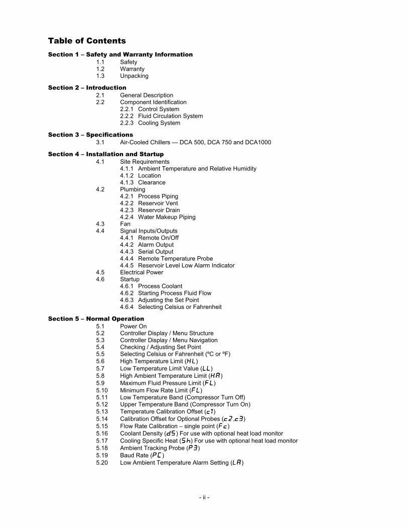
Table of Contents
Section 1 – Safety and Warranty Information
1.1 Safety 1.2 Warranty 1.3 Unpacking
Section 2 – Introduction
2.1 General Description 2.2 Component Identification
2.2.1 Control System 2.2.2 Fluid Circulation System 2.2.3 Cooling System
Section 3 – Specifications
3.1 Air-Cooled Chillers — DCA 500, DCA 750 and DCA1000
Section 4 – Installation and Startup
4.1 Site Requirements 4.1.1 Ambient Temperature and Relative Humidity 4.1.2 Location 4.1.3 Clearance
4.2 Plumbing 4.2.1 Process Piping 4.2.2 Reservoir Vent 4.2.3 Reservoir Drain 4.2.4 Water Makeup Piping
4.3 Fan 4.4 Signal Inputs/Outputs
4.4.1 Remote On/Off 4.4.2 Alarm Output 4.4.3 Serial Output 4.4.4 Remote Temperature Probe 4.4.5 Reservoir Level Low Alarm Indicator
4.5 Electrical Power 4.6 Startup
4.6.1 Process Coolant 4.6.2 Starting Process Fluid Flow 4.6.3 Adjusting the Set Point 4.6.4 Selecting Celsius or Fahrenheit
Section 5 – Normal Operation
5.1 Power On 5.2 Controller Display / Menu Structure 5.3 Controller Display / Menu Navigation 5.4 Checking / Adjusting Set Point 5.5 Selecting Celsius or Fahrenheit (ºC or ºF)
5.6 High Temperature Limit (HLHLHLHL) 5.7 Low Temperature Limit Value (LLLLLLLL) 5.8 High Ambient Temperature Limit (HAHAHAHA)
5.9 Maximum Fluid Pressure Limit (FLFLFLFL) 5.10 Minimum Flow Rate Limit (FLFLFLFL) 5.11 Low Temperature Band (Compressor Turn Off) 5.12 Upper Temperature Band (Compressor Turn On)
5.13 Temperature Calibration Offset (c1c1c1c1) 5.14 Calibration Offset for Optional Probes (c2c2c2c2,c3c3c3c3) 5.15 Flow Rate Calibration – single point (FcFcFcFc) 5.16 Coolant Density (dSdSdSdS) For use with optional heat load monitor
5.17 Cooling Specific Heat (ShShShSh) For use with optional heat load monitor 5.18 Ambient Tracking Probe (P3P3P3P3) 5.19 Baud Rate (PCPCPCPC) 5.20 Low Ambient Temperature Alarm Setting (LALALALA)
- ii -

5.21 Password (PdPdPdPd) 5.22 Time Delay (tdtdtdtd) 5.23 Controller Operating, Alarm, and Error Messages 5.24 Remote On/Off 5.25 Alarm Output 5.26 Loss of Power 5.27 Adjusting the High Pressure Bypass Setting 5.28 Enabling/Disabling the Local Lockout 5.29 Automatic Restart from Alarm Mode 5.30 Fuse Bits
Section 6 – Routine Maintenance
6.1 Recommended Routine Maintenance Schedule 6.2 Routine Maintenance Procedures
6.2.1 Inline Strainer 6.2.2 Reservoir Coolant Level 6.2.3 Coolant Freeze Protection 6.2.4 Air Filters (Air-Cooled Chillers only)
Section 7 – Troubleshooting
7.1 Unit Will Not Operate (no cooling or pumping) 7.2 No Pumping 7.3 Insufficient Pumping 7.4 No Cooling or Insufficient Cooling 7.5 Triac Failure 7.6 Internal Probe Failure 7.7 Ambient Tracking Probe Failure 7.8 Diagnostic Mode 7.9 Resetting the High Refrigerant Pressure Safety Cutout
Section 8 - Service and Technical Support
Appendix
A.1 Flow Diagram A.2.1 Wiring Diagram 5 – 7.5 HP A.2.2 Wiring Diagram 10 HP A.3 Glycol Chart
This symbol marks chapters and sections of this instruction manual which are particularly relevant to safety. When attached to the unit, this symbol draws attention to the relevant section of the instruction manual.
This symbol indicates that hazardous voltages may be present.
Read all instructions pertaining to safety, set-up, and operation.
Proper operation is the users’ responsibility.
- iii -

- 1 -
Section 1 – Safety and Warranty Information
1.1 Safety
It is the user’s responsibility to read and understand all instructions and safety precautions included in this manual prior to installing or operating this equipment. Contact our Customer Service Department with any questions regarding the operation of this chiller or the information contained in this manual.
Installation, operation, or maintenance of this equipment should be performed in strict accordance with the instructions outlined in this manual. Failure to follow those instructions may increase the risk of personal injury, damage the equipment, and/or void the warranty.
Exercise care when unloading, loading, rigging, or moving this equipment.
All warning labels should be carefully observed. Never remove or obstruct a warning label.
Make sure that ventilation is adequate when welding or brazing around this equipment. Protect adjacent materials from flames or sparks. Keep an approved fire extinguisher close at hand.
Always operate this equipment within the stated design specifications.
Be sure to remove power from the equipment, reclaim the refrigeration charge, and relieve any residual pressure before cutting into the refrigeration system.
Do not attempt to operate leaking or damaged equipment.
Service should only be performed by fully qualified personnel.
Follow all applicable electrical and safety codes when connecting power to this equipment.
Do not attempt to override the power interlock switch or any other safety features on this equipment.

- 2 -
Always remove power from the equipment prior to performing any service or maintenance.
Do not move the equipment without first disconnecting power.
Make sure the equipment’s main power switch is in the OFF position before connecting or disconnecting power.
Additional Precautions
Do not attempt to operate this equipment without an appropriate cooling fluid in the reservoir.
Always empty to the fluid reservoir before moving the unit.
1.2 Warranty
Thank you for purchasing this chiller. We are confident it will serve you for a long time. Our warranty to you is as follows:
The manufacturer agrees to correct for the original user of this product, either by repair, or at the manufacturer's election, by replacement, any defect that develops after delivery of this product within the period as stated on the warranty card. In the event of replacement, the replacement unit will be warranted for 90 days or warranted for the remainder of the original unit’s parts or labor warranty period, whichever is longer.
If this product requires service, contact the manufacturer/supplier's office for instructions. When return of the product is necessary, a return authorization number will be assigned and the product should be shipped, (transportation charges pre-paid), to the indicated service center. To insure prompt handling, the return authorization number should be placed on the outside of the package and a detailed explanation of the defect enclosed with the item.
This warranty shall not apply if the defect or malfunction was caused by accident, neglect, unreasonable use, improper service, or other causes not arising out of defects in material or workmanship. There are no warranties, expressed or implied, including, but not limited to, those of merchantability or fitness for a particular purpose which extends beyond the description and period set forth herein.
The manufacturer's sole obligation under this warranty is limited to the repair or replacement of a defective product and shall not, in any event, be liable for any incidental or consequential damages of any kind resulting from use or possession of this product. Some states do not allow: (A) limitations on how long an implied warranty lasts; or (B) the exclusion or limitation of incidental or consequential damages, so the above limitations or exclusions may not apply to you. This warranty gives you specific legal rights. You may have other rights that vary from state to state.
1.3 Unpacking
Your chiller is shipped in a special container. Retain the container and all packing materials until the unit is completely assembled and working properly. Set up and run the unit immediately to confirm proper operation. Beyond one week, your unit may be warranty repaired, but not replaced. If the unit is damaged or does not operate properly, contact the transportation company, file a damage claim and contact the company where your unit was purchased immediately.

- 3 -
Section 2 – Introduction
2.1 General Description
The PolyScience® DuraChill™ line of industrial chillers offers exceptional performance, reliability,
and operational simplicity. Available in both air- and water-cooled models, these robust self-contained chillers are engineered to provide accurate temperature control in a wide range of process cooling applications.
These powerful chillers can be configured with a wide variety of standard and optional features, including:
Standard
• Process temperatures from 32° to 86°F (0° to 30°C)
• Ambient temperatures from 60° to 95°F (16° to 35°C)
• ±2°F (±1.11°C) temperature stability
• High efficiency vertical air exhaust
• Accurate microprocessor control with LED temperature readout
• Remote On/Off capability
• RS232 interface for remote control and data logging
• Over/under temperature process fluid alarms
• Copeland Scroll® compressor
• Stainless steel centrifugal pump
• Integral pump and compressor protection
• Locking casters
• NEMA 12 style electrical enclosure with door-mounted power disconnect
• Power phase monitor
• Full Flow Bypass Valve
Optional
• Extended ambient temperatures (60° to 104°F / 16° to 40°C)
• Extended ambient temperatures (30° to 104°F / -1° to 40°C)
• Higher output centrifugal or turbine pump
• RS485 serial output
• Tank fluid level indicator
• Remote temperature probe
• Stainless steel reservoir
• Automatic water make-up valve
• DI water compatible process piping
• Secondary pump
• Process water side-stream filter
• Rail or foot mounting
• Audible and visual alarm indicators
• Variable speed fan
• Heaters
• Process shutoff valves
• Soft start fan motor
• Low tank level indicator/alarm
An application data sheet showing how your chiller is equipped is included with the documentation that accompanied this manual.
- 4 -
2.2 Component Identification
Your Model 500 - 750 - 1000 Chiller consists of three basic sub-systems:
• Control system
• Fluid circulation system
• Cooling system
This section describes these sub-systems in detail and includes information on the available options. Please note that your chiller may or may not be equipped with all the components discussed.
See Sections A.1 and A.2.
2.2.1 Control System
This system controls and monitors Chiller operation. It consists of a microprocessor-based controller linked to the various sensors, gauges, valves, switches, and signal input/output connections on the unit.
Control Panel — Temperature set point, temperature units, and other operating parameters are set via the Control Panel. Operating information is displayed on a local LED readout. A remote Control Panel is available as an option.
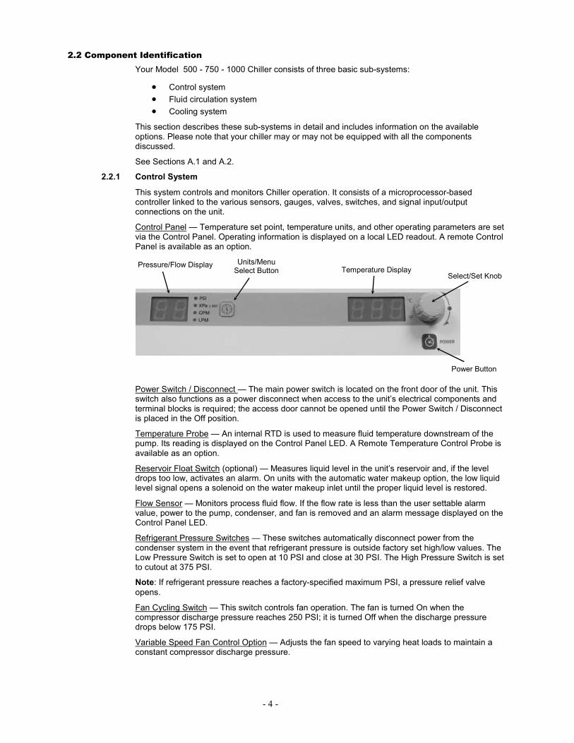
Power Switch / Disconnect — The main power switch is located on the front door of the unit. This switch also functions as a power disconnect when access to the unit’s electrical components and terminal blocks is required; the access door cannot be opened until the Power Switch / Disconnect is placed in the Off position.
Temperature Probe — An internal RTD is used to measure fluid temperature downstream of the pump. Its reading is displayed on the Control Panel LED. A Remote Temperature Control Probe is available as an option.
Reservoir Float Switch (optional) — Measures liquid level in the unit’s reservoir and, if the level drops too low, activates an alarm. On units with the automatic water makeup option, the low liquid level signal opens a solenoid on the water makeup inlet until the proper liquid level is restored.
Flow Sensor — Monitors process fluid flow. If the flow rate is less than the user settable alarm value, power to the pump, condenser, and fan is removed and an alarm message displayed on the Control Panel LED.
Refrigerant Pressure Switches — These switches automatically disconnect power from the condenser system in the event that refrigerant pressure is outside factory set high/low values. The Low Pressure Switch is set to open at 10 PSI and close at 30 PSI. The High Pressure Switch is set to cutout at 375 PSI.
Note: If refrigerant pressure reaches a factory-specified maximum PSI, a pressure relief valve
opens.
Fan Cycling Switch — This switch controls fan operation. The fan is turned On when the compressor discharge pressure reaches 250 PSI; it is turned Off when the discharge pressure drops below 175 PSI.
Variable Speed Fan Control Option — Adjusts the fan speed to varying heat loads to maintain a constant compressor discharge pressure.
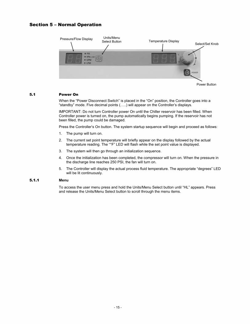
Units/Menu Select Button
Select/Set Knob
Power Button
Pressure/Flow Display Temperature Display

- 5 -
Low Ambient Operating Package Option – The front fan is controlled by a speed control that senses the temperature of the liquid refrigerant as it leaves the condenser. The fan is full on above 85°F and off below 50°F. The fan will run at reduced speed between these temperatures.
Serial Output — For remote computer control. RS232 output standard; RS485 output optional.
2.2.2 Fluid Circulation System
This system governs the circulation of fluid through the unit.
Reservoir Tank — This polyethylene tank is used to maintain stable temperature control and an adequate reserve of fluid for the system. It may be equipped with an optional float switch that monitors fluid level and activates an alarm or opens the automatic water makeup solenoid valve if the level drops too low. A stainless steel reservoir tank is available as an option.
Tank Sight Glass or Level Indicator — This indicator serves as a convenient means of checking the liquid level within the Reservoir Tank.
Automatic Water Makeup System — This optional system consists of a Solenoid Valve connected to a water makeup line. It is used to automatically maintain fluid in the Reservoir Tank at adequate levels. The customer is responsible for installing an appropriate back flow prevention system on the inlet to this system.
Process Pump — This stainless steel pump is used to pump fluid from the Reservoir Tank to the process. Optional centrifugal and turbine pumps are available for applications requiring higher pressures or flow rates.
Recirculation Pump — An optional pump installed for special applications.
Strainer — Traps debris which could potentially clog the Evaporator.
Evaporator — Serves as the heat exchanger between the refrigeration and fluid flow system. Used to cool fluid before it returns to process.
Flow Sensor — Monitors process fluid flow. If the flow rate is less than 30% of the Chiller’s nominal flow rate, then power to the pump, condenser, and fan is removed and an alarm message displayed on the Control Panel LED.
RTD Temperature Probe — Measures temperature of process fluid downstream of the pump. This is the temperature used to determine cooling demand.
Pressure Sensor — Measures fluid pressure at the outlet of the Chiller.
Bypass Valve — Used to prevent overloading of pump in the event that the process piping becomes restricted or clogged. Diverts flow from process line back to evaporator and Reservoir Tank.
Process Water Side-Stream Filter System — This optional system consists of a Flow Meter (set at 1 GPM), Filter (50 micron), and Ball Valve. It is used to filter particulate from a portion of the process fluid flow.
2.2.3 Cooling System
The condenser on your Chiller is air-cooled. The following components are common to all systems.
Common Cooling System Components
Evaporator — Serves as the heat exchanger between the refrigeration and fluid flow system. Cools fluid before it returns to process.
Compressor — The unit incorporates a 5 to 10 HP Copeland Scroll® compressor. The Compressor
is protected from overloads through high and low refrigerant pressure cutouts.
Filter Dryer — Removes residual particulate and moisture from the refrigeration system. Must be replaced whenever the sealed refrigeration lines are opened for service.
Sight Glass — Used to observe refrigerant liquid flow to Evaporator.
Expansion Valve — Controls refrigerant superheat at the outlet of the Evaporator to prevent liquid from returning to the compressor.
Hot Gas Bypass Solenoid Valve — Injects refrigerant vapor into the Evaporator to stabilize temperature control when operating at less than a full heat load.
- 6 -
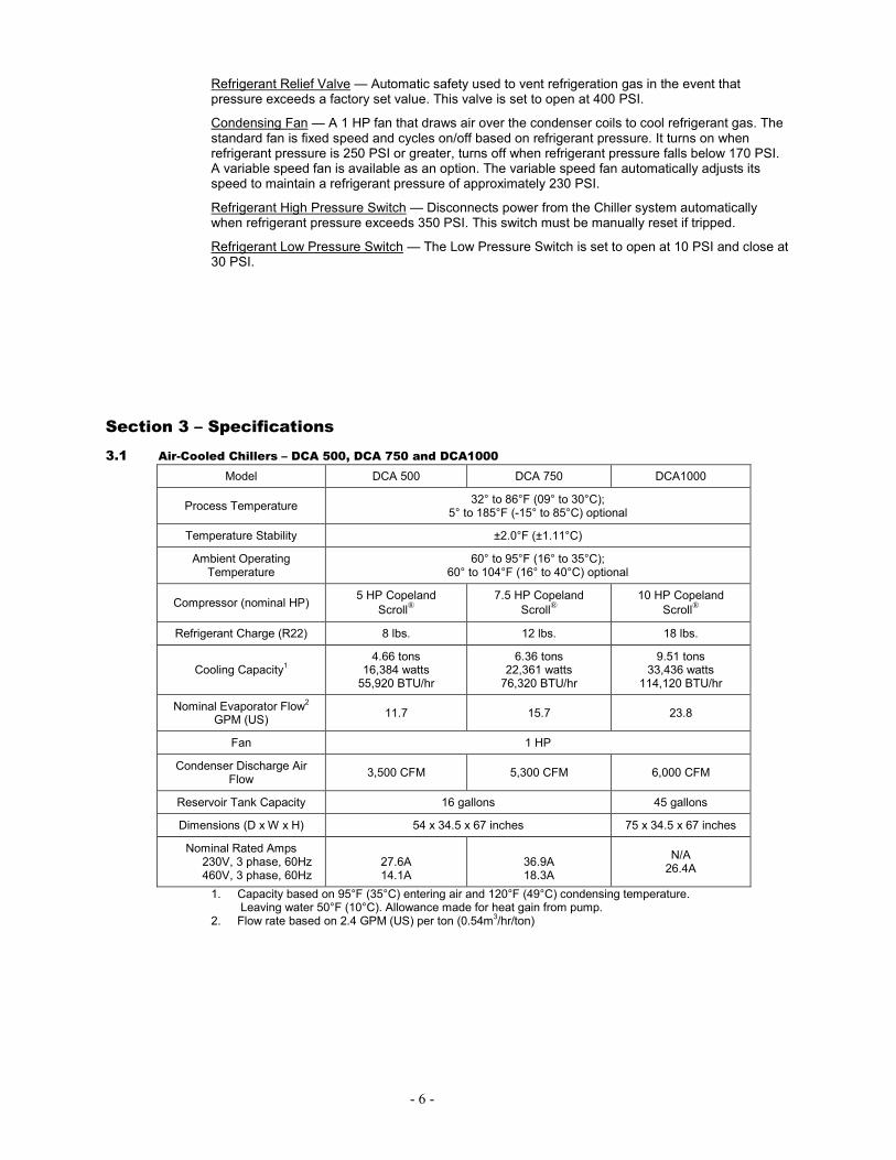
Refrigerant Relief Valve — Automatic safety used to vent refrigeration gas in the event that pressure exceeds a factory set value. This valve is set to open at 400 PSI.
Condensing Fan — A 1 HP fan that draws air over the condenser coils to cool refrigerant gas. The standard fan is fixed speed and cycles on/off based on refrigerant pressure. It turns on when refrigerant pressure is 250 PSI or greater, turns off when refrigerant pressure falls below 170 PSI. A variable speed fan is available as an option. The variable speed fan automatically adjusts its speed to maintain a refrigerant pressure of approximately 230 PSI.
Refrigerant High Pressure Switch — Disconnects power from the Chiller system automatically when refrigerant pressure exceeds 350 PSI. This switch must be manually reset if tripped.
Refrigerant Low Pressure Switch — The Low Pressure Switch is set to open at 10 PSI and close at 30 PSI.
Section 3 – Specifications
3.1 Air-Cooled Chillers – DCA 500, DCA 750 and DCA1000
Model DCA 500 DCA 750 DCA1000
Process Temperature 32° to 86°F (09° to 30°C);
5° to 185°F (-15° to 85°C) optional
Temperature Stability ±2.0°F (±1.11°C)
Ambient Operating Temperature
60° to 95°F (16° to 35°C); 60° to 104°F (16° to 40°C) optional
Compressor (nominal HP) 5 HP Copeland
Scroll®
7.5 HP Copeland
Scroll®
10 HP Copeland
Scroll®
Refrigerant Charge (R22) 8 lbs. 12 lbs. 18 lbs.
Cooling Capacity1
4.66 tons 16,384 watts 55,920 BTU/hr
6.36 tons 22,361 watts 76,320 BTU/hr
9.51 tons 33,436 watts
114,120 BTU/hr
Nominal Evaporator Flow2
GPM (US) 11.7 15.7 23.8
Fan 1 HP
Condenser Discharge Air Flow
3,500 CFM 5,300 CFM 6,000 CFM
Reservoir Tank Capacity 16 gallons 45 gallons
Dimensions (D x W x H) 54 x 34.5 x 67 inches 75 x 34.5 x 67 inches
Nominal Rated Amps 230V, 3 phase, 60Hz 460V, 3 phase, 60Hz
27.6A 14.1A
36.9A 18.3A
N/A 26.4A
1. Capacity based on 95°F (35°C) entering air and 120°F (49°C) condensing temperature. Leaving water 50°F (10°C). Allowance made for heat gain from pump. 2. Flow rate based on 2.4 GPM (US) per ton (0.54m
3/hr/ton)

- 7 -
RS-232
REMOTE ON / OFFSTATUS ALARM
WATER LEVELSIGHT GLASS
LINE"POWER IN"
OUTLET
INLET
A
Section 4 – Installation and Startup
Figure 4-1
4.1 Site Requirements
4.1.1 Ambient Temperature and Relative Humidity
The Chiller is designed for indoor installation in ambient temperatures between 60° and 95°F (16° to 35°C); relative humidity should be between 20% and 80% (non-condensing).
4.1.2 Location
The Chiller should be installed on a level surface capable of supporting 1625 pounds (737 kg) or more and should be located as close to possible to the process requiring cooling. It should not be installed closer than 4 feet (1.4 meters) to a heat generating source, such as heating pipes, boilers, etc.). If possible, it should be located near a suitable drain to prevent flooding in the event of leaks.
For ease of positioning and maneuverability, the Chiller is supplied with four heavy-duty locking casters (standard). Rail and foot-mounting are available as options.
4.1.3 Clearance
At least 18 to 24 inches (45.7 to 61 cm) of clearance should be allowed on the front, sides, and rear of the Chiller for access to connections and components. Chillers (DCA 500, DCA 750, and DCA 1000) require at least 4 feet (1.4 meters) of overhead clearance to dissipate the exhaust from the Chiller’s top-mounted fan.

- 8 -
4.2 Plumbing
See Figure 4-1.
4.2.1 Process Piping
The Chiller incorporates two female NPT fittings on the rear of the enclosure for the process inlet and outlet connections. It is strongly recommended that shutoff valves be installed on both of these connections.
To maintain a safe workplace and to avoid leaks, special care should be taken when choosing hoses and connections for the Chiller.
• Pressure Ratings — Hoses should be able to withstand a minimum of 100 PSI.
• Flexible Tubing — Avoid tubing that will expand and take up fluid volume when operating at the desired pressure.
• Couplings and Clamps — The use of screw-tightened hose clamps is necessary on all joints to insure good, tight connections. Quick connectors are not recommended as they have the potential for restricting flow rate.
4.2.2 Reservoir Vent
A ¾ inch female NPT connection is provided for the reservoir vent line. This vent is intended to prevent siphoning and/or overflows in the event of a problem with process liquid circulation. The vent pipe should extend to a height at least 6 to 12 inches (15.2 to 30.5 cm) above the process equipment. If desired you may fill the chiller through vent fitting providing the reservoir cap is off to let air escape.
4.2.3 Reservoir Drain
A ¾ inch female NPT connection is provided for the reservoir’s gravity drain. It should be piped to a drain or receptacle positioned lower than the bottom of the reservoir. If a receptacle is used, be sure is of sufficient volume to hold all the water in the reservoir, process, and process lines.
4.2.4 Water Makeup Piping
If your Chiller is equipped with the Automatic Water Makeup option, a ¾ inch NPT fitting is provided for this connection. It is the user’s responsibility to connect a suitable backflow prevention device on this supply line.
4.3 Fan
The Chiller’s fan may be allowed to exhaust freely into the area in which the unit is located or may be vented to an exhaust duct of the appropriate size. If it is connected to an exhaust duct, the duct work should incorporate an auxiliary blower to prevent back pressure from impacting fan operation.

- 9 -
1
23
4
5
3
54
21
ALARM OUTPUT(SHOWN IN NORMALRUNNING POSITION)
PROCESS CHILLER
REMOTE ON /OFFCLOSE TO TURN CHILLER OFF
(USER SUPPLIED)
VIEWINGREAR OUTSIDE OF CHILLER
4.4 Signal Inputs/Outputs
See Figures 4-1 and 4-2.
All signal input/output connections are made on the rear of the Chiller. These connections should be made before connecting electrical power to the Chiller or beginning startup procedures.
4.4.1 Remote On/Off
See Figure 4-2.
This allows the user to turn the Chiller On and Off using a remote dry contact. The Chiller is On when the contact is open; it is Off when the contact is closed. A 10-ft. cord and connector are provided.
NOTE: When the Remote On/Off contact is closed, the On/Off button on the Chiller’s front panel is disabled, preventing the unit from being turned On and Off locally.
4.4.2 Alarm Output
See Figure 4-2.
This allows the user to connect a remote alarm device to the Chiller. The alarm output consists of NO and NC contacts which are switched whenever an alarm, fault, or error condition is detected. A 10-ft. cord and connector are provided.
Figure 4-2
4.4.3 Serial Output
Serial Connector — A 9-pin D-connector is provided on the back panel of the Chiller for RS232 data communication. A serial cable that uses only the following pins should be used to connect the Chiller to the computer:
Pin #2 — data read (data from computer) Pin #3 — data transmit (data to computer) Pin #5 — Signal ground
RS232 Protocol — The Controller uses the following RS232 protocol: Data bits — 8 Parity — None Stop bits — 1 Flow control — None Baud rate — Selectable (Chiller and PC baud rates must match).
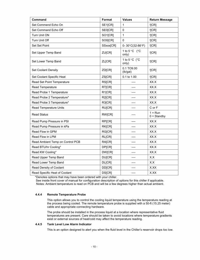
Communications Commands — Commands must be entered in the exact format shown. Do not send a [LF] (line feed) after the [CR] (character return). Be sure to follow character case exactly.
A response followed by an exclamation point (!) indicates that a command was executed correctly. A question mark (?) indicates that the Chiller could not execute the command (either because it was in an improper format or the values were outside the allowable range). A response must be received from the Chiller before another command can be sent. All responses are terminated with a single carriage return [CR].
- 10 -
Command Format Values Return Message
Set Commend Echo On SE1[CR] 1 ![CR]
Set Command Echo Off SE0[CR] 0 ![CR]
Turn Unit ON SO1[CR] 1 ![CR]
Turn Unit Off SO0[CR] 0 ![CR]
Set Set Point SSxxx[CR] 0- 30°C(32-86°F) ![CR]
Set Upper Temp Band ZU[CR] 1 to 5 °C (°C only)
![CR]
Set Lower Temp Band ZL[CR] 1 to 5 °C (°C only)
![CR]
Set Coolant Density ZD[CR] 0.1 TO9.00 (lb/gal)
![CR]
Set Coolant Specific Heat ZS[CR] 0.1 to 1.00 ![CR]
Read Set Point Temperature RS[CR] ---- XX.X
Read Temperature RT[CR] ---- XX.X
Read Probe 1 Temperature R1[CR] ---- XX.X
Read Probe 2 Temperature* R2[CR] ---- XX.X
Read Probe 3 Temperature* R3[CR] ---- XX.X
Read Temperature Units RU[CR] ---- C or F
Read Status RW[CR] ---- 1 = Run 0 = Standby
Read Pump Pressure in PSI RP[CR] ---- XX.X
Read Pump Pressure in kPa RK[CR] ---- XX.X
Read Flow in GPM RG[CR] ---- XX.X
Read Flow in LPM RL[CR] ---- XX.X
Read Ambient Temp on Control PCB RA[CR] ---- XX.X
Read BTU/hr Cooling* DP[CR] ---- XX.X
Read KW Cooling* DW[CR] ---- XX.X
Read Upper Temp Band DU[CR] ---- X.X
Read Lower Temp Band DL[CR] ---- X.X
Read Density of Coolant DD[CR] ---- X.XX
Read Specific Heat of Coolant DS[CR] ---- X.XX
*Denotes options that may have been ordered with your chiller. See inside front cover of manual for configuration description of options for this chiller if applicable. Notes: Ambient temperature is read on PCB and will be a few degrees higher than actual ambient.
4.4.4 Remote Temperature Probe
This option allows you to control the cooling liquid temperature using the temperature reading at the process being cooled. The remote temperature probe is supplied with a 50-ft (15.25 meter) cable and appropriate connecting hardware.
The probe should be installed in the process liquid at a location where representative fluid temperatures are present. Care should be taken to avoid locations where temperature gradients exist or external sources of heat/cold may affect the temperature reading.
4.4.5 Tank Level Low Alarm Indicator
This is an option designed to alert you when the fluid level in the Chiller’s reservoir drops too low.
- 11 -
4.5 Electrical Power
All electrical connections should be made by a qualified, licensed electrician. Proper building codes and safety regulations should be followed.
Make sure that the power supply to the Chiller is the same voltage, frequency, and phase as indicated on the identification label.
The Chiller is designed with a junction box on the rear of the unit to connect the electrical power supply conduit. See Figure 4-1.
Be sure to connect the wires in the proper phase sequence. I.e., L1,L2, and L3. Provide suitable conduit strain relief and grounding.
Your chiller is equipped with a phase monitor. It is located inside the controls enclosure. It will prevent startup if phase connection is incorrect. It will also turn the chiller off in the event of a loss of one phase. It will also prevent chiller operation if the voltage mismatch between any two phases is greater than 8%.
Once the power connection has been made, the enclosure door closed, and the Power Switch/Disconnect placed in the On position, you are ready for Chiller startup.
NOTE: When the Power Switch/Disconnect is placed in the On position, five decimal points (…..) will appear on the Controller’s LED displays. This signifies that the Controller is in “standby” and ready for power up.
IMPORTANT: Do not turn Controller power On until the Chiller reservoir has been filled. When Controller power is turned On, the pump automatically begins pumping. If the reservoir has not been filled, the pump could be damaged.
Turn main power Off before filling the reservoir.

- 12 -
Air Filter
In-LineStrainer
ReservorCap
CaptiveScrewsSecureAccessPanel
PowerDisconnect
Switch
Remove FrontPanel to Access
Pump and Bypass Valve
4.6 Startup
See Figure 4-3.
IMPORTANT: Be sure to turn main power Off before filling the reservoir.
Figure 4-3
4.6.1 Process Coolant
Suitable Fluids
IMPORTANT: Only use fluids that will satisfy safety, health, and equipment compatibility requirements. Caustic, corrosive, or flammable fluids must never be used.
The Chiller is designed to accommodate a variety of coolant fluids, such as water, glycol mixtures, etc. For most applications above 15°C (59°F), distilled water is satisfactory. For operation below 15°C (59°F), the Chiller must be protected with an antifreeze solution. Ethylene glycol (laboratory grade) or propylene glycol(laboratory grade) and water in a 50/50 mixture is satisfactory from +15° to 0°C (59° to 32°F). Select a fluid that is compatible with the Chiller’s wetted parts of brass, copper, polyethylene, polypropylene, PVC, nylon, and stainless steel.
See glycol curves in appendix.
Use Polyscience Catalog No. 004-300040 Algaecide or equivalent to prevent algae growth.
NOTE: Do not fill the reservoir with deionized water unless your Chiller is equipped with the DI water compatible piping option.
The following fluids are not recommended and may cause damage to the unit: – Any flammable fluids – Chlorides or bleach – Automotive antifreeze with additives – Strong concentrations of any acid or bases – Mild concentrations of any acid with the following elements (or Halides) in their formulas: Chlorine (Cl), Fluorine (F), Sulfur (S), Chromium salts.

- 13 -
Do not use flammable fluids as a fire hazard may result.
WARNING: Operation below 15°C (59°F) requires antifreeze in the circulating fluid.
Filling the Reservoir
See Figure 4-3.
Remove the panel from the rear left side of the enclosure. It is held in place with ¼-20 Philips head captive screws.
Remove the filler cap from the reservoir and fill it to a level approximately 2 inches (5.1 cm) from the top of the reservoir. Do not replace the cap at this time.
If the Chiller is equipped with the Automatic Water Makeup option, open any user-installed valves on the makeup water supply line.
NOTE: The Automatic Water Makeup system is controlled by the Chiller. When additional liquid is called for, the system’s valve will open to bring the fluid level in the reservoir up to the proper level. However, this system does begin operating when Controller power is turned on. When using automatic water makeup, the cooling fluid should be periodically checked for proper freeze protection.
4.6.2 Starting Process Fluid Flow
If so equipped, open the valves on the process inlet and outlet lines.
If the Chiller is water-cooled (DCW models), open any user-provided valves on the condenser cooling water lines.
Turn main power On.
NOTE: When the Power Switch/Disconnect is placed in the On position, five decimal points (…..) will appear on the Controller’s LED displays. This signifies that the Controller is in “standby” and ready for power up.
WARNING: The first time the chiller is operated it should be run overnight in the
standby mode. The compressor crankcase heater will boil off any refrigerant absorbed in the compressor oil.
IMPORTANT: Do not turn Controller power On until the Chiller reservoir has been
filled. When Controller power is turned On, the pump automatically begins pumping. If the reservoir has not been filled, the pump could be damaged.
Press the Controller’s “POWER” button. The system startup sequence will begin and proceed as follows:
• The pump will turn on.
• The current set point temperature will briefly appear on the “Temperature Display”. After a short time delay or upon pressing the knob the actual temperature reading will appear. The right decimal point on the “Temperature Display” will flash while the set point value is displayed.
• The system will then go through a short initialization sequence.
- 14 -
• Once the initialization has been completed, the compressor will turn on. When the pressure in the discharge line reaches 250 PSI, the fan will turn on (air-cooled models) or the condenser water regulating valve (water-cooled units) will open.
• The Controller will display the actual process fluid temperature. The appropriate “degrees” LED will be lit continuously.
Check the fluid level in the reservoir. The liquid level should drop as fluid flows to the process. Slowly add fluid to the reservoir until the level in the reservoir stops going down. This means that the system is filled and any entrained air purged. If the Chiller is equipped with the Automatic Water Makeup option, fluid will be added automatically. Replace the reservoir cap and securely tighten.
Check for leaks in the process lines and at the process line connections.
Check flow rate on front panel. For best performance, system flow rate should be within 80 to 150% of the nominal flow rate found in the specifications above for your model chiller.
4.6.3 Adjusting the Set Point
NOTE: The factory default set point temperature is 50°F (10°C).
Press the Select/Set Knob on the front panel. The current set point temperature will be displayed and the decimal point at the bottom right of the display will flash, indicating the temperature can be changed.
Rotate the Select/Set Knob until the desired set point temperature is displayed. The setting is accepted after either pressing the Select/Set Knob a second time or will be accepted automatically after a few seconds of inactivity. NOTE: This function is not available when the optional ambient
tracking probe is installed and enabled.
4.6.4 Selecting Celsius or Fahrenheit
The chiller as supplied will read in °F.
The LEDs adjacent to the Temperature Display indicate the unit of measure (°C or °F). To change from °C to °F or vice versa, proceed as follows:
To change to °F — Place the main Disconnect Switch on the front of the chiller in the “Off” position. Press and hold the Units/Menu Select Button while returning the Disconnect Switch to the “On” position.
To change to °C — Place the main Disconnect Switch on the front of the chiller in the “Off” position. Press and hold the Power Button on the front panel while returning the Disconnect Switch to the “On” position.
IMPORTANT: All user settings, except baud rate and calibration offset, return to the original factory
defaults when the unit in which temperature is displayed is changed. The Chiller’s temperature set point and various alarm settings should be reset to the desired values.
- 15 -
Section 5 – Normal Operation
5.1 Power On
When the “Power Disconnect Switch” is placed in the “On” position, the Controller goes into a “standby” mode. Five decimal points (…..) will appear on the Controller’s displays.
IMPORTANT: Do not turn Controller power On until the Chiller reservoir has been filled. When Controller power is turned on, the pump automatically begins pumping. If the reservoir has not been filled, the pump could be damaged.
Press the Controller’s On button. The system startup sequence will begin and proceed as follows:
1. The pump will turn on.
2. The current set point temperature will briefly appear on the display followed by the actual temperature reading. The “°F” LED will flash while the set point value is displayed.
3. The system will then go through an initialization sequence.
4. Once the initialization has been completed, the compressor will turn on. When the pressure in the discharge line reaches 250 PSI, the fan will turn on.
5. The Controller will display the actual process fluid temperature. The appropriate “degrees” LED will be lit continuously.
5.1.1 Menu
To access the user menu press and hold the Units/Menu Select button until “HL” appears. Press and release the Units/Menu Select button to scroll through the menu items.
Units/Menu Select Button
Select/Set Knob
Power Button
Pressure/Flow Display Temperature Display
- 16 -
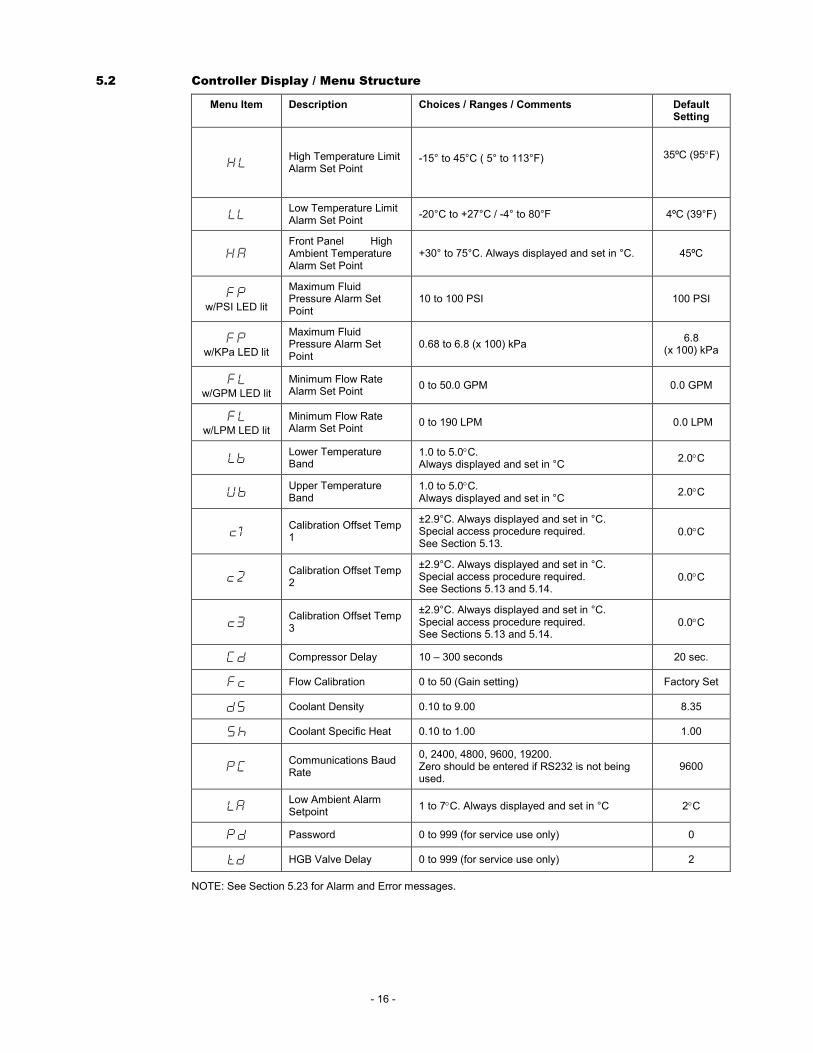
5.2 Controller Display / Menu Structure
Menu Item Description Choices / Ranges / Comments Default Setting
HL High Temperature Limit Alarm Set Point
-15° to 45°C ( 5° to 113°F)
35ºC (95°F)
LL Low Temperature Limit Alarm Set Point
-20°C to +27°C / -4° to 80°F 4ºC (39°F)
HA Front Panel High Ambient Temperature Alarm Set Point
+30° to 75°C. Always displayed and set in °C. 45ºC
FP
w/PSI LED lit
Maximum Fluid Pressure Alarm Set Point
10 to 100 PSI 100 PSI
FP
w/KPa LED lit
Maximum Fluid Pressure Alarm Set Point
0.68 to 6.8 (x 100) kPa 6.8
(x 100) kPa
FL w/GPM LED lit
Minimum Flow Rate Alarm Set Point
0 to 50.0 GPM 0.0 GPM
FL w/LPM LED lit
Minimum Flow Rate Alarm Set Point
0 to 190 LPM 0.0 LPM
Lb Lower Temperature Band
1.0 to 5.0°C. Always displayed and set in °C
2.0°C
Ub Upper Temperature Band
1.0 to 5.0°C. Always displayed and set in °C
2.0°C
c1 Calibration Offset Temp 1
±2.9°C. Always displayed and set in °C. Special access procedure required. See Section 5.13.
0.0°C
c2 Calibration Offset Temp 2
±2.9°C. Always displayed and set in °C. Special access procedure required. See Sections 5.13 and 5.14.
0.0°C
c3 Calibration Offset Temp 3
±2.9°C. Always displayed and set in °C. Special access procedure required. See Sections 5.13 and 5.14.
0.0°C
Cd Compressor Delay 10 – 300 seconds 20 sec.
Fc Flow Calibration 0 to 50 (Gain setting) Factory Set
dS Coolant Density 0.10 to 9.00 8.35
Sh Coolant Specific Heat 0.10 to 1.00 1.00
PC Communications Baud Rate
0, 2400, 4800, 9600, 19200. Zero should be entered if RS232 is not being used.
9600
LA Low Ambient Alarm Setpoint
1 to 7°C. Always displayed and set in °C 2°C
Pd Password 0 to 999 (for service use only) 0
td HGB Valve Delay 0 to 999 (for service use only) 2
NOTE: See Section 5.23 for Alarm and Error messages.
- 17 -
5.3 Controller Display / Menu Navigation
Actual Fluid Temperature — Fluid temperature leaving the chiller is displayed on the right hand LED display.
Pressure and Flow Rate -- The pump pressure and flow rate are displayed on the left hand LED display. Press and release the Units/Menu Select button to choose the measurement to be displayed.
Set Point Temperature — The set point temperature can be checked at any time by pressing the Select/Set knob.
Operational Setup Menus and Values — Operational Setup Menus are accessed by pressing and
holding the Units/Menu Select button until “HLHLHLHL” is displayed. Continued pressing of the Units/Menu Select button will scroll through the menu.
Menu parameters are changed by turning the Select/Set knob. Displayed values can be accepted by pressing either the Select /Set knob or simply allowing a few seconds to pass without any keypad activity.
NOTE: After a few seconds of keypad inactivity, the Controller automatically returns to the normal operating display.
5.4 Checking / Adjusting the Set Point
NOTE: The factory default set point temperature is 50°F (10°C).
Press the Select/Set Knob on the front panel. The current set point temperature will be displayed and the decimal point at the bottom right of the display will flash, indicating the temperature can be changed.
Rotate the Select/Set Knob until the desired set point temperature is displayed. The setting is accepted after either pressing the Select/Set Knob a second time or will be accepted automatically after a few seconds of inactivity. NOTE: This function is not available when the optional ambient
tracking probe is installed and enabled.
5.5 Selecting Celsius or Fahrenheit (°C or °F)
The LEDs adjacent to the Temperature Display indicate the unit of measure (°C or °F). To change from °C to °F or vice versa, proceed as follows:
To change to °F — Place the main Disconnect Switch on the front of the chiller in the “Off” position. Press and hold the Units/Menu Select Button while returning the Disconnect Switch to the “On” position.
To change to °C — Place the main Disconnect Switch on the front of the chiller in the “Off” position. Press and hold the Power Button on the front panel while returning the Disconnect Switch to the “On” position.
IMPORTANT: All user settings, except baud rate and calibration offset, return to the original factory
defaults when the unit in which temperature is displayed is changed. The Chiller’s temperature set point and various alarm settings should be reset to the desired values.
- 18 -
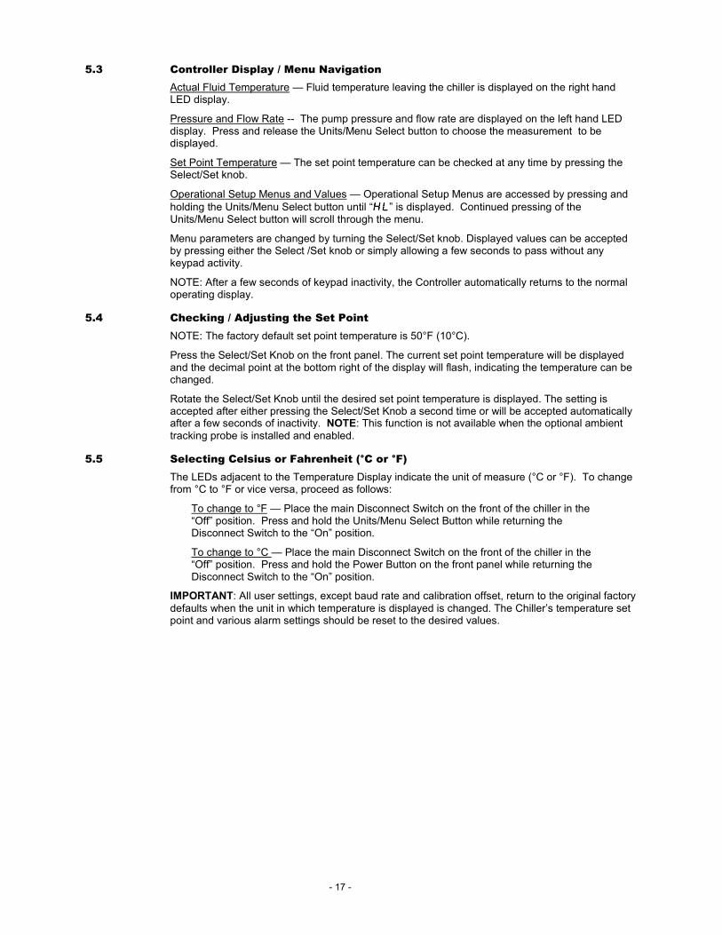
5.6 High Temperature Limit (HLHLHLHL) This menu item serves two functions. First, it establishes the maximum allowable set point temperature and thus helps prevent an operator from inadvertently setting the temperature set point above a pre-established temperature. Secondly, it serves as a high temperature alarm, automatically activating both audio and visual alarm indicators when the measured fluid
temperature reaches the HL setting. The compressor, heater, fan, and pump will also turn off. To change the high temperature limit value, rotate the Select/Set Knob until the desired value is displayed on the temperature display.
HLHLHLHL 35353535.0000
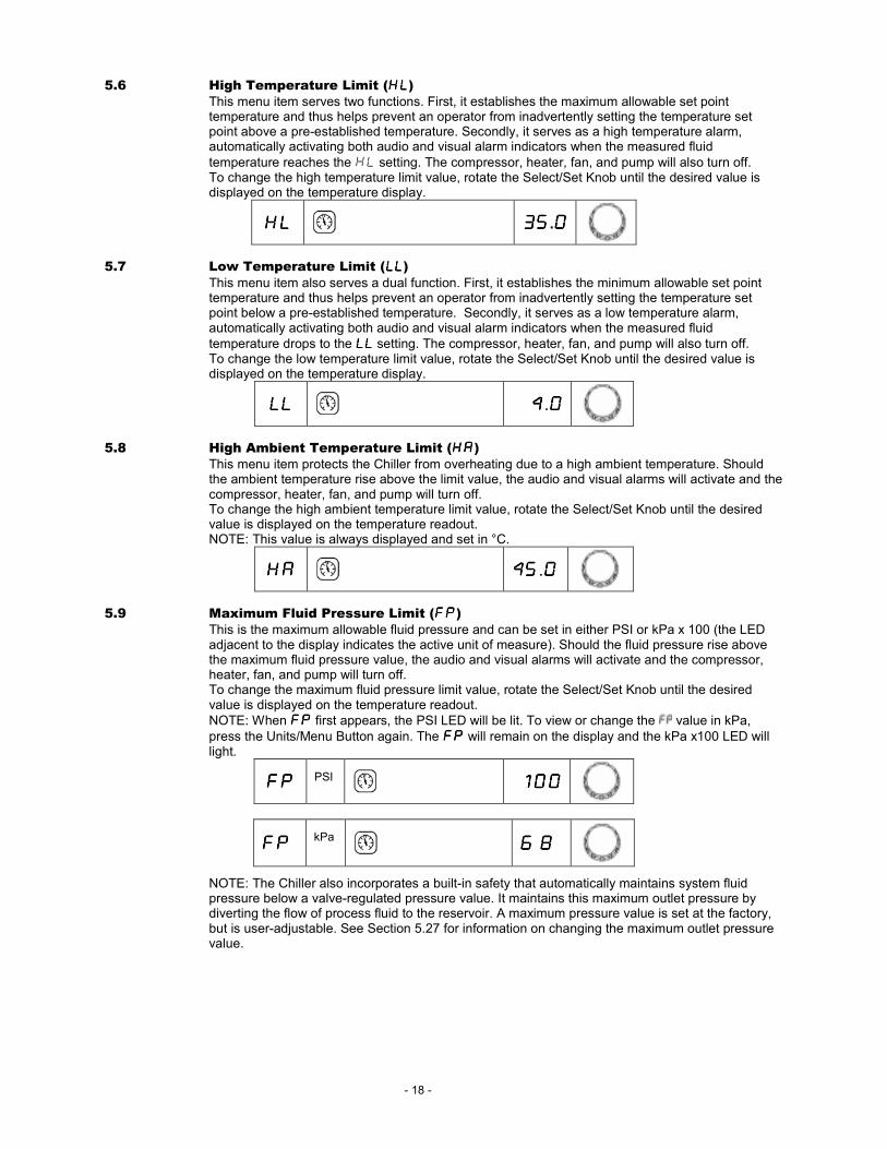
5.7 Low Temperature Limit (LLLLLLLL)
This menu item also serves a dual function. First, it establishes the minimum allowable set point temperature and thus helps prevent an operator from inadvertently setting the temperature set point below a pre-established temperature. Secondly, it serves as a low temperature alarm, automatically activating both audio and visual alarm indicators when the measured fluid
temperature drops to the LLLLLLLL setting. The compressor, heater, fan, and pump will also turn off. To change the low temperature limit value, rotate the Select/Set Knob until the desired value is displayed on the temperature display.
LLLLLLLL 4444.0000
5.8 High Ambient Temperature Limit (HHHHAAAA) This menu item protects the Chiller from overheating due to a high ambient temperature. Should the ambient temperature rise above the limit value, the audio and visual alarms will activate and the compressor, heater, fan, and pump will turn off. To change the high ambient temperature limit value, rotate the Select/Set Knob until the desired value is displayed on the temperature readout. NOTE: This value is always displayed and set in °C.
HAHAHAHA 44445555.0000
5.9 Maximum Fluid Pressure Limit (FPFPFPFP) This is the maximum allowable fluid pressure and can be set in either PSI or kPa x 100 (the LED adjacent to the display indicates the active unit of measure). Should the fluid pressure rise above the maximum fluid pressure value, the audio and visual alarms will activate and the compressor, heater, fan, and pump will turn off. To change the maximum fluid pressure limit value, rotate the Select/Set Knob until the desired value is displayed on the temperature readout.
NOTE: When FPFPFPFP first appears, the PSI LED will be lit. To view or change the value in kPa,
press the Units/Menu Button again. The FPFPFPFP will remain on the display and the kPa x100 LED will light.
FPFPFPFP
PSI 100100100100
FPFPFPFP kPa
6.86.86.86.8
NOTE: The Chiller also incorporates a built-in safety that automatically maintains system fluid pressure below a valve-regulated pressure value. It maintains this maximum outlet pressure by diverting the flow of process fluid to the reservoir. A maximum pressure value is set at the factory, but is user-adjustable. See Section 5.27 for information on changing the maximum outlet pressure value.

- 19 -
5.10 Minimum Flow Rate Limit (FLFLFLFL))))) This is the minimum allowable flow rate and can be set in either GPM or LPM (the LED adjacent to the display indicates the active unit of measure). Should the fluid flow rate drop below the minimum flow rate value, the audio and visual alarms will activate and the compressor, heater, fan, and pump will turn off. To change the minimum flow rate value, rotate the Select/Set Knob until the desired flow rate value is displayed on the temperature readout.
NOTE: When first appears, the GPM LED will be lit. To view or change the FLFLFLFLvalue in LPM, press the Units/Menu Button again. The FLFLFLFL will remain on the display and the LPM LED will light.
FLFLFLFL GPM 0000.0000
FLFLFLFL LPM
0.00.00.00.0
5.11 Lower Temperature Band (Compressor Turn Off)
This menu item provides access to the Lower control band value. This is the amount below set point that the process temperature can drop before the compressor turns off. It is useful at heat
loads less than 30% of full capacity. The highest setting of 5.0°C will give longest compressor life.
The lowest setting of 1.0°C will give best temperature stability. Recommended setting is 3.0°C
(5.4°F).
LbLbLbLb 2222.0000 °C
5.12 Upper Temperature Band (Compressor Turn On)
This menu item provides access to the Upper control band value. This is the amount above set point that the process temperature can rise before the compressor turns on. It is useful at heat
loads less than 30% of full capacity. The highest setting of 5.0°C will give longest compressor life.
The lowest setting of 1.0°C will give best temperature stability. Recommended setting is 2.0°C
(3.6°F).
UbUbUbUb 2222.0000 °C
5.13 Temperature Calibration Offset (c1c1c1c1)
This menu item allows you to adjust the Chiller’s displayed temperature reading to match that of a traceable standard. It allows you to offset the displayed temperature value by as much as ±1.9°C. NOTE: Calibration offset values are always set and displayed in °C. To prevent the operator from accidentally changing the calibration offset, a special sequence of keystrokes is required to access this function.
1. Press and hold the Units/Menu Button until HLHLHLHL appears on the display. 2. Press and release the Units/Menu Button until UbUbUbUb appears on the display. 3. Press and hold the Units/Menu Button. 4. While holding the Units/Menu Button, press and release the Select/Set Knob.
5. When CALCALCALCAL appears on the temperature readout, release the Units/Menu Button. The current calibration offset value will appear on the temperature readout. Notice that the display will alternate between the offset value and the calibrated temperature.
6. Rotate the Select/Set Knob until the desired calibration offset is displayed. Press the Select/Set Knob or simply allow the display to time out to accept the displayed value.
c1c1c1c1 0000.0000
5.14 Calibration Offset for Optional Probes (c2c2c2c2,c3c3c3c3)
If optional temperature probes 2 and 3 have been installed, these can be offset as in 5.13 above.
- 20 -
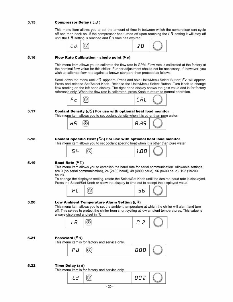
5.15 Compressor Delay ( CdCdCdCd )
This menu item allows you to set the amount of time in between which the compressor can cycle
off and then back on. If the compressor has turned off upon reaching the LBLBLBLB setting it will stay off until the UBUBUBUB setting is reached and CdCdCdCd time has expired. .
Cd 20202020
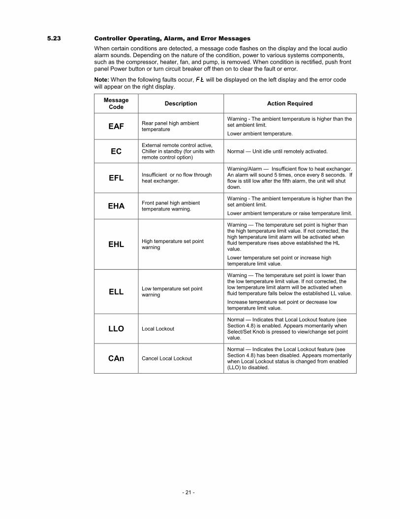
5.16 Flow Rate Calibration – single point (FcFcFcFc)
This menu item allows you to calibrate the flow rate in GPM. Flow rate is calibrated at the factory at the nominal flow value for this chiller. Further adjustment should not be necessary. If, however, you wish to calibrate flow rate against a known standard then proceed as follows.
Scroll down the menu until c3c3c3c3 appears. Press and hold Units/Menu Select Button; FcFcFcFc will appear. Press and release Set/Select Knob. Release the Units/Menu Select Button. Turn Knob to change flow reading on the left hand display. The right hand display shows the gain value and is for factory reference only. When the flow rate is calibrated, press Knob to return to normal operation.
FcFcFcFc CALCALCALCAL
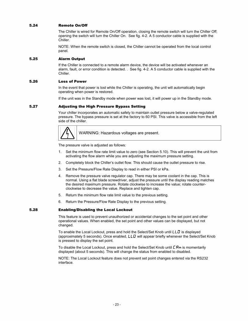
5.17 Coolant Density (dSdSdSdS) For use with optional heat load monitor
This menu item allows you to set coolant density when it is other than pure water.
dSdSdSdS 8888.35353535
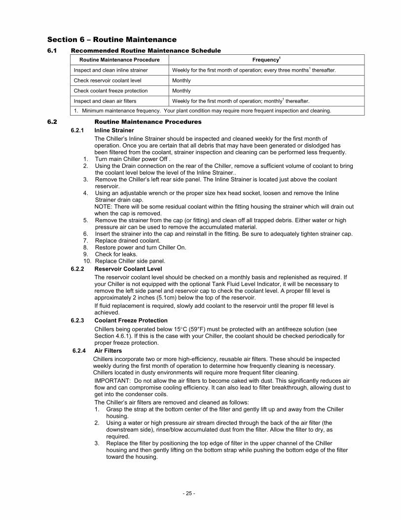
5.18 Coolant Specific Heat (ShShShSh) For use with optional heat load monitor
This menu item allows you to set coolant specific heat when it is other than pure water.
ShShShSh 1111.00000000
5.19 Baud Rate (PCPCPCPC) This menu item allows you to establish the baud rate for serial communication. Allowable settings are 0 (no serial communication), 24 (2400 baud), 48 (4800 baud), 96 (9600 baud), 192 (19200 baud). To change the displayed setting, rotate the Select/Set Knob until the desired baud rate is displayed. Press the Select/Set Knob or allow the display to time out to accept the displayed value.
PCPCPCPC 96969696
5.20 Low Ambient Temperature Alarm Setting (LALALALA) This menu item allows you to set the ambient temperature at which the chiller will alarm and turn off. This serves to protect the chiller from short cycling at low ambient temperatures. This value is always displayed and set in °C.
LALALALA 0.0.0.0.2222
5.21 Password (PdPdPdPd) This menu item is for factory and service only.
PdPdPdPd 000000000000
5.22 Time Delay (tdtdtdtd)
This menu item is for factory and service only.
tdtdtdtd 002002002002
- 21 -
5.23 Controller Operating, Alarm, and Error Messages
When certain conditions are detected, a message code flashes on the display and the local audio alarm sounds. Depending on the nature of the condition, power to various systems components, such as the compressor, heater, fan, and pump, is removed. When condition is rectified, push front panel Power button or turn circuit breaker off then on to clear the fault or error.
Note: When the following faults occur, FtFtFtFt will be displayed on the left display and the error code will appear on the right display.
Message Code
Description Action Required
EAF Rear panel high ambient temperature
Warning - The ambient temperature is higher than the set ambient limit.
Lower ambient temperature.
EC External remote control active, Chiller in standby (for units with remote control option)
Normal — Unit idle until remotely activated.
EFL Insufficient or no flow through heat exchanger.
Warning/Alarm — Insufficient flow to heat exchanger. An alarm will sound 5 times, once every 8 seconds. If flow is still low after the fifth alarm, the unit will shut down.
EHA Front panel high ambient temperature warning.
Warning - The ambient temperature is higher than the set ambient limit.
Lower ambient temperature or raise temperature limit.
EHL High temperature set point warning
Warning — The temperature set point is higher than the high temperature limit value. If not corrected, the high temperature limit alarm will be activated when fluid temperature rises above established the HL value.
Lower temperature set point or increase high temperature limit value.
ELL Low temperature set point warning
Warning — The temperature set point is lower than the low temperature limit value. If not corrected, the low temperature limit alarm will be activated when fluid temperature falls below the established LL value.
Increase temperature set point or decrease low temperature limit value.
LLO Local Lockout
Normal — Indicates that Local Lockout feature (see Section 4.8) is enabled. Appears momentarily when Select/Set Knob is pressed to view/change set point value.
CAn Cancel Local Lockout
Normal — Indicates the Local Lockout feature (see Section 4.8) has been disabled. Appears momentarily when Local Lockout status is changed from enabled (LLO) to disabled.

- 22 -
Ft appears on the left hand display 01010101 Factory Reserved None.
02020202 Low limit temperature alarm Alarm — Process fluid temperature has dropped to low temperature limit value. Compressor, heater, fan, and pump turned off. Increase heat load on Chiller or decrease low temperature limit value.
03030303 High limit temperature alarm Alarm — Process fluid temperature has reached high temperature limit value. Compressor, heater, fan, and pump turned off. Decrease heat load on Chiller or increase high temperature limit value.
04040404
Over-temperature protection alarm
(Select models only)
Alarm — Process fluid temperature is above Chiller’s factory set high temperature safety cutoff. Power to condenser, heater, and fan turned off; pump remains on. Lower process temperature.
05050505 Low liquid level alarm
(Select models only)
Delayed Alarm — Activated when the liquid level in the reservoir falls below an acceptable level for 30 seconds of longer. Compressor, heater, fan, and pump turned off. Add fluid to reservoir.
06060606 High bath temperature alarm
(Select models only)
Alarm — Fluid temperature has exceeded 82°C (180°F). Compressor, heater, fan, and pump turned off.
Lower fluid temperature.
07070707 Low flow alarm
Alarm — Flow rate has dropped below minimum flow rate setting. Power to compressor, heater, fan, and pump turned off. Note: Disabled during first 2 minutes of operation.
Correct cause of low flow rate or decrease minimum flow rate setting.
08080808 High pressure alarm
Delayed Alarm — Activated when fluid outlet pressure has exceeded high-pressure limit value for 30 seconds. Compressor, heater, fan, and pump turned off.
Decrease outlet pressure by removing blockage or increase high-pressure temperature limit value.
09090909 Internal software fault Fault — Power to compressor, heater, fan, and pump turned off. Reset default values; see Section 4.6.4.
10101010 Triac fault Fault — Power to compressor, heater, fan, and pump turned off. Contact supplier.
11111111 Internal probe (P1) fault Fault — Faulty internal temperature probe. Power to compressor, heater, fan, and pump turned off. Contact supplier.
12121212 Water inlet probe (P2) fault Fault — Faulty water inlet temperature probe. Power to compressor, heater, fan, and pump turned off. Contact supplier.
13131313 Communications fault Fault — Internal electronics failure. Power to compressor, heater, fan, and pump turned off. Contact supplier.
14141414 ADC fault, internal probe Fault — ADC for internal probe faulty. Power to compressor, heater, fan, and pump turned off. Contact supplier.
15151515 ADC fault, external probe Fault — ADC for external probe faulty. Power to compressor, heater, fan, and pump turned off. Contact supplier.
16161616 Front panel high ambient temperature alarm
Alarm — Ambient temperature at front panel is higher than high ambient temperature limit. Compressor, heater, fan, and pump turned off. Occurs when ambient temperature exceeds the set ambient limit by 5ºC or more.
Lower temperature in area in which Chiller is located or increase high ambient temperature limit value. Temperature limit is adjustable.
17171717
Rear panel high ambient temperature alarm
(select models only)
Alarm — Ambient temperature at rear panel is higher than high ambient temperature limit. Compressor, heater, fan, and pump turned off. Occurs when the ambient temperature exceeds the ambient limit.
Lower temperature in area in which Chiller is located or increase high ambient temperature limit value. Temperature limit is not adjustable.
18181818 Ambient temperature probe (P3) fault
Fault — Faulty internal temperature probe. Power to compressor, heater, fan, and pump turned off. Replace ambient tracking probe or operate Chiller using internal temperature probe. Contact supplier if problem persists.
19191919 Pump overload (DAP1) fault Fault — Power to compressor, heater, fan, and pump turned off. See Section 7 – Troubleshooting.
20202020 Compressor overload (DAF2) fault
Fault — Power to compressor, heater, fan, and pump turned off. See Section 7 – Troubleshooting.
21212121 Fan overload (DAF1) fault Fault — Power to compressor, heater, fan, and pump turned off. See Section 7 – Troubleshooting.
22222222 Pump 2 overload (DAP2) fault
(Select models only) Fault — Power to compressor, heater, fan, and pump turned off. See Section 7 – Troubleshooting.
- 23 -
5.24 Remote On/Off
The Chiller is wired for Remote On/Off operation, closing the remote switch will turn the Chiller Off; opening the switch will turn the Chiller On. See fig. 4-2. A 5 conductor cable is supplied with the Chiller.
NOTE: When the remote switch is closed, the Chiller cannot be operated from the local control panel.
5.25 Alarm Output
If the Chiller is connected to a remote alarm device, the device will be activated whenever an alarm, fault, or error condition is detected. . See fig. 4-2. A 5 conductor cable is supplied with the Chiller.
5.26 Loss of Power
In the event that power is lost while the Chiller is operating, the unit will automatically begin operating when power is restored.
If the unit was in the Standby mode when power was lost, it will power up in the Standby mode.
5.27 Adjusting the High Pressure Bypass Setting
Your chiller incorporates an automatic safety to maintain outlet pressure below a valve-regulated pressure. The bypass pressure is set at the factory to 60 PSI. This valve is accessible from the left side of the chiller.
WARNING: Hazardous voltages are present.
The pressure valve is adjusted as follows:
1. Set the minimum flow rate limit value to zero (see Section 5.10). This will prevent the unit from activating the flow alarm while you are adjusting the maximum pressure setting.
2. Completely block the Chiller’s outlet flow. This should cause the outlet pressure to rise.
3. Set the Pressure/Flow Rate Display to read in either PSI or kPa.
4. Remove the pressure valve regulator cap. There may be some coolant in the cap. This is normal. Using a flat blade screwdriver, adjust the pressure until the display reading matches the desired maximum pressure. Rotate clockwise to increase the value; rotate counter-clockwise to decrease the value. Replace and tighten cap.
5. Return the minimum flow rate limit value to the previous setting.
6. Return the Pressure/Flow Rate Display to the previous setting.
5.28 Enabling/Disabling the Local Lockout
This feature is used to prevent unauthorized or accidental changes to the set point and other operational values. When enabled, the set point and other values can be displayed, but not changed.
To enable the Local Lockout, press and hold the Select/Set Knob until LLOLLOLLOLLO is displayed
(approximately 5 seconds). Once enabled, LLOLLOLLOLLO will appear briefly whenever the Select/Set Knob is pressed to display the set point.
To disable the Local Lockout, press and hold the Select/Set Knob until CAnCAnCAnCAn is momentarily displayed (about 5 seconds). This will change the status from enabled to disabled.
NOTE: The Local Lockout feature does not prevent set point changes entered via the RS232 interface.

- 24 -
5.29 Automatic Restart from Alarm Mode
This chiller is equipped with an automatic restart feature to avoid false alarms. If any alarm condition is detected the chiller will turn off, wait 30 seconds and then turn on. This is to avoid nuisance trips due to temporary flow obstructions, temperature swings or electrical line noise. Three restart attempts will be made. If the alarm condition continues to exist then an alarm will sound and the chiller will remain off until the problem is corrected.
5.30 Fuse Bits
This menu item allows you to select logic levels for these optional features.
- Remote dry contact on / off - Remote 24 V on / off - Reservoir Float Switch
To set fuse bits turn power off. While pressing knob and power button at the same time turn power switch on. Left display will show “Fb” and right hand display will show “h” followed by two digits, you may set by turning the knob. Press and release knob or wait and menu will time out with new setting.
LOGIC STATE h00 h01 h02 h03 h04 h05 h06
DRY CONTACT CLOSED TURNS UNIT
OFF TURNS UNIT
ON TURNS UNIT
OFF TURNS UNIT
ON
DRY CONTACT OPEN TURNS UNIT
ON TURNS UNIT
OFF
DISABLED
TURNS UNIT ON
TURNS UNIT OFF
DISABLED
24 VOLTS TURNS UNIT
OFF TURNS UNIT
ON TURNS UNIT
OFF TURNS UNIT
ON
O VOLTS TURNS UNIT
ON
DISABLED
TURNS UNIT OFF
TURNS UNIT ON
DISABLED
TURNS UNIT OFF
FLOAT SWITCH OPEN LEVEL OK LEVEL OK LEVEL OK LEVEL LOW LEVEL LOW LEVEL LOW
FLOAT SWITCH CLOSED LEVEL LOW LEVEL LOW LEVEL LOW
NOT USED
LEVEL OK LEVEL OK LEVEL OK
.
- 25 -
Section 6 – Routine Maintenance
6.1 Recommended Routine Maintenance Schedule
Routine Maintenance Procedure Frequency1
Inspect and clean inline strainer Weekly for the first month of operation; every three months1 thereafter.
Check reservoir coolant level Monthly
Check coolant freeze protection Monthly
Inspect and clean air filters Weekly for the first month of operation; monthly1 thereafter.
1. Minimum maintenance frequency. Your plant condition may require more frequent inspection and cleaning.
6.2 Routine Maintenance Procedures
6.2.1 Inline Strainer
The Chiller’s Inline Strainer should be inspected and cleaned weekly for the first month of operation. Once you are certain that all debris that may have been generated or dislodged has been filtered from the coolant, strainer inspection and cleaning can be performed less frequently.
1. Turn main Chiller power Off . 2. Using the Drain connection on the rear of the Chiller, remove a sufficient volume of coolant to bring
the coolant level below the level of the Inline Strainer.. 3. Remove the Chiller’s left rear side panel. The Inline Strainer is located just above the coolant
reservoir. 4. Using an adjustable wrench or the proper size hex head socket, loosen and remove the Inline
Strainer drain cap. NOTE: There will be some residual coolant within the fitting housing the strainer which will drain out when the cap is removed.
5. Remove the strainer from the cap (or fitting) and clean off all trapped debris. Either water or high pressure air can be used to remove the accumulated material.
6. Insert the strainer into the cap and reinstall in the fitting. Be sure to adequately tighten strainer cap. 7. Replace drained coolant. 8. Restore power and turn Chiller On. 9. Check for leaks. 10. Replace Chiller side panel.
6.2.2 Reservoir Coolant Level
The reservoir coolant level should be checked on a monthly basis and replenished as required. If your Chiller is not equipped with the optional Tank Fluid Level Indicator, it will be necessary to remove the left side panel and reservoir cap to check the coolant level. A proper fill level is approximately 2 inches (5.1cm) below the top of the reservoir.
If fluid replacement is required, slowly add coolant to the reservoir until the proper fill level is achieved.
6.2.3 Coolant Freeze Protection
Chillers being operated below 15°C (59°F) must be protected with an antifreeze solution (see Section 4.6.1). If this is the case with your Chiller, the coolant should be checked periodically for proper freeze protection.
6.2.4 Air Filters
Chillers incorporate two or more high-efficiency, reusable air filters. These should be inspected weekly during the first month of operation to determine how frequently cleaning is necessary. Chillers located in dusty environments will require more frequent filter cleaning.
IMPORTANT: Do not allow the air filters to become caked with dust. This significantly reduces air flow and can compromise cooling efficiency. It can also lead to filter breakthrough, allowing dust to get into the condenser coils.
The Chiller’s air filters are removed and cleaned as follows: 1. Grasp the strap at the bottom center of the filter and gently lift up and away from the Chiller
housing. 2. Using a water or high pressure air stream directed through the back of the air filter (the
downstream side), rinse/blow accumulated dust from the filter. Allow the filter to dry, as required.
3. Replace the filter by positioning the top edge of filter in the upper channel of the Chiller housing and then gently lifting on the bottom strap while pushing the bottom edge of the filter toward the housing.

- 26 -
Section 7 – Troubleshooting
WARNING: Refer servicing to qualified service personnel. When power is on, dangerous voltages exist within chassis components. Use extreme care when measuring voltages on live circuits.
7.1 Unit Will Not Operate (no cooling or pumping)
• Check that the power cord is plugged in to an operating electrical outlet.
• Check that the Circuit Breaker/Power Switch is ON.
• Check that the front panel Power Switch is ON.
7.2 No Pumping
• Check the fluid level in the whole system to make sure the pump is receiving fluid.
• Check if the pump motor is operating.
• Check for blockage within the circulating system.
7.3 Insufficient Pumping
• Check for low line voltage.
• Check for too small of a hose diameter.
• Check for too high of a fluid viscosity.
• Check for restrictions in the connecting tubing.
7.4 No Cooling or Insufficient Cooling
• Check for low or high line voltage.
• Check for blocked airflow through ventilation screens.
• Check ambient air temperature. High air temperature may cause the refrigeration compressor to temporarily shut down.
• Check for excessive heat being transferred to the cooling fluid liquid as this may exceed the cooling capacity of the refrigeration system.
7.5 Triac Failure
• Triac fault message appears on the display, indicating that the triac has failed or the line supply voltage has a source of extreme interference from other equipment. Plug the unit into another power source. If it still displays triac failure, a triac or triac driver needs replacement.
7.6 Internal Probe Failure
• The Internal Probe failure message appears on the display, indicating that the internal probe has failed or there is a problem with the circuitry reading the probe signal. Contact supplier.
7.7 Ambient Tracking Probe Failure
• The Ambient Tracking Probe failure message appears on the display, indicating that a problem with the probe has been detected.
• Check the integrity of the ambient tracking probe connection to make certain that the probe has not been unplugged.
• Replace the ambient tracking probe.
• If the problem persists, operate Chiller using internal temperature probe and contact supplier.

- 27 -
7.8 Diagnostic Mode
The Chiller incorporates a Diagnostic mode, which displays important operational information that can aid in troubleshooting. To access the Diagnostic mode, press and hold knob; press and release units/menu select (left hand) button.
The diagnostic menu appears on the left hand display; the current value for the diagnostic item appears on the temperature readout. Turning the knob toggles through the various Diagnostic menu items
NOTE: Diagnostic items are display values only. They cannot be changed.
Menu Item Description
AtAtAtAt Ambient temperature at front panel
ECECECEC External voltage control
LnLnLnLn Line voltage to control PCB (nominal 120VAC)
PbPbPbPb KBTU/HR Heat Load (optional)
PUPUPUPU KW Heat Load (optional)
HPHPHPHP High Side Refrigerant Pressure (psi)
HCHCHCHC High Side Refrigerant Temperature (°C)
CtCtCtCt Chiller type (factory use only)
FbFbFbFb Fuse bits (remote control voltage, contact closures, etc.)
P1P1P1P1 Probe 1 Temperature – Leaving Water
P2P2P2P2 Probe 2 Temperature
P3P3P3P3 Probe 3 Temperature
7.9 Resetting the High Refrigerant Pressure Safety Cutout
An excessive ambient and/or process heat load can cause the Chiller’s high refrigerant pressure safety cutout to activate, removing power from the compressor and (on air-cooled Chillers) fan. The safety is factory-set to activate at a refrigerant pressure of 350 PSI.
To reset the high refrigerant pressure safety cutout switch, proceed as follows:
1. Correct the condition causing the excessive head load.
2. Turn power to the Chiller OFF.
3. Remove the Chiller’s right front side panel.
4. Locate the high refrigerant pressure safety cutout switch. It is located near the compressor discharge and has a blue housing with red reset button.
5. Press the reset button on the top of the switch. There should be a tactile and/or audible click as it resets.
NOTE: Allow sufficient time (approximately 15 minutes) for the pressure in the refrigeration system to decrease below 350 PSI before resetting the safety switch. If the reset action seems “soft” or the Chiller will not resume operation on power up, it’s likely that the refrigerant pressure is still above the 350 PSI cutout value.
6. Replace the side panel.
7. Turn power to the Chiller back ON and resume normal operation.
- 28 -
Section 8 – Service and Technical Support
If you have followed the troubleshooting steps outlined in Section 7 and your Chiller still fails to operate properly, contact the supplier from whom the unit was purchased. Have the following information available for the customer service person:
� Model, Serial Number, and Voltage (from side panel label)
• Date of purchase and purchase order number
� Supplier’s order number or invoice number
� A summary of the problem
FLOWSWITCH
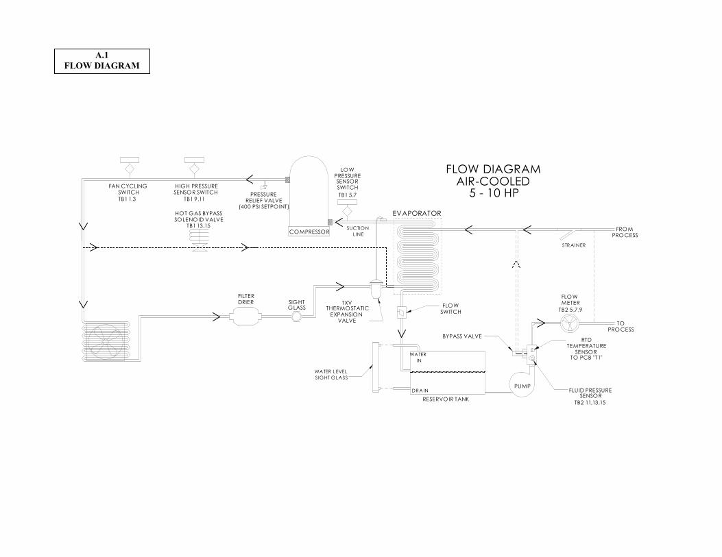
FLOW DIAGRAMAIR-COOLED
5 - 10 HPTB1 5,7
TB1 13,15
TB1 9,11TB1 1,3
PROCESS
TO PCB "T1"
FLUID PRESSURESENSOR
TB2 11,13,15
WATER
IN
DRAIN
WATER LEVEL
SIGHT GLASS
SOLENOID VALVEHOT GAS BYPASS
TOPROCESS
STRAINER
EVAPORATOR
RESERVOIR TANK
PUMP
RTDTEMPERATURE
SENSOR
BYPASS VALVE
FLOWMETER
LOWPRESSURESENSORSWITCH
COMPRESSORSUCTION
LINE
PRESSURERELIEF VALVE
(400 PSI SETPOINT)
HIGH PRESSURESENSOR SWITCH
FAN CYCLINGSWITCH
TXVTHERMOSTATIC
EXPANSION VALVE
FILTERDRIER SIGHT
GLASS
FROM
TB2 5,7,9
A.1
FLOW DIAGRAM
525-814
PULLUP
RESISTORS
G
PHASEMONITOR
225-130SHUNT
GBX2
H4
X1
XF120 VAC
TRANSFORMER120/24VAC OUTPUT
24 VAC
REARPANEL
BLK
WHTBLK
WHTBLK
RED
BLK
BLU
17
12
15
23
10
3
9
7
21
6
8
20
24
16
18
19
13
1
4
11
22
2
14
5
2 1
12
12
12
122 12 12 12 1
12 12 12 12 12 12 13 213 213 234 1234 1234 1234 12
TB 3
FUSEBLOCK
CA
B D
CA
B D
YEL
9
8
7
6
5
4
3
2
1
GROUND BAR
TB 2
TB 2
TB 1
TB 1
STATUS ALARM CONTACTS
HOT GAS BYPASS VALVE
A2
A1
A2
A1
COMPRESSOR
PUMP
GRN/YEL
BLK
WHT
BLK
WHT
GRN/YEL
BLK
WHT
FLUID PRESSURE SENSOR
FLOW METER
REMOTE CUTOFF SWITCH
BLKBLK
YELYEL
BLUBLU
WHTBLURED
WHT
WHT
BLU
BLU
BLKBLK
REDGRNWHT
WHTGRNRED
WHT
BLK
WHT
RED
BLKGRN
BLKGRN
RED
REDWHTBLK
GRNBLK
GRN
REDWHTBLK
BRNBLK
POWERSUPPLY
GB
GB
NC
NO
NC
NO
NO
NC
COMPRESSORPUMP
FUSEBLOCK
CONTACTOR
OVERLOAD RELAY
CONTACTOR
FUSEBLOCK
FAN
NC
FUSEBLOCK
OVERLOAD RELAY
NC
NO
A1
CONTACTOR
NO
A2
DISTRIBUTIONBLOCK
FRONT PANELDISCONNECT
SWITCH
L3L2L1
D
C
B
A
WH
T
BLK
YEL
GRN
RED
200-284
PCB U4 PIN 1PCB XFMR 1 PIN 10
PCB U4 PIN 4
215-513
3
15
1
2
200-280BEAD
GB
EMIFILTER
CRANKCASEHEATER
FAN
8
7 6
4
5
2
1
3
FAN(S) OVERLOAD RELAY (NC)
PUMP OVERLOAD RELAY (NC)
GB
DCMPDHRN PRK DPMP DFANPWR FAN HTR OTP CMP PMP
STA
1 2 3 4 56 87 9
12
123
1 2 3D232
RTD 100TEMP. SENSOR
1234
HEFHITFPSDHPSDLPS RC
V
RC
S
FLW
DA
F2
DA
P1
DA
P2
DA
F1
T3T2T1/ITS
5
342
1
CONT 5
RS-232
63
74 2 1589
FLUID PRESSURESENSOR
FLOWMETER
BLKGRN
RED
HOTGAS
BYPASSVALVE
REFRIGERANT HIGHPRESSURE SWITCH
REFRIGERANT LOWPRESSURE SWITCH
FAN CYCLINGPRESSURE SWITCH
13
3
16
2
21
6
9
7
2019
15
11
22
17
1
18
12
10
8
4
23 24
14
5
GBGB GB
L1 L2 L3
JUNCTION BOX(REAR OF UNIT)
GROUND
SUPPLY VOLTAGEOUTPUT
OUTPUTGROUND
SUPPLY VOLTAGE
COMNO
NC
NCCOMNO
12
FAN
BLK BLK WHT
BLUBRN
SWITCH
BLK
FLOW
230V = H2460V = H1
RCFILTER
RCFILTER
RCFILTER
RJ-45
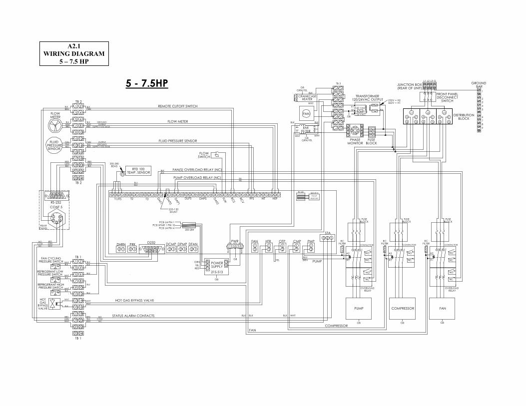
5 - 7.5HP
A2.1
WIRING DIAGRAM
5 – 7.5 HP
FILTER
525-814
PULLUP
RESISTORS
REARPANEL
BLK
WHTBLK
WHTBLK
RED
BLK
BLU
17
12
15
23
10
3
9
7
21
6
8
20
24
16
18
19
13
1
4
11
22
2
14
5
2 1
1
2
1
2
1
2
1
22 12 12 12 1
12 12 12 12 12 12 13 213 213 234 1234 1234 1234 12
TB 3
FUSEBLOCK
CA
B D
CA
B D
YEL
98
7
6
54
32
1
GROUND BAR
TB 2
TB 2
TB 1
TB 1
STATUS ALARM CONTACTS
HOT GAS BYPASS VALVE
BLU BLU
A2
A1
A2
A1 A1
A2
COMPRESSOR
PUMP
GRN/YEL
BLK
WHT
BLK
WHT
GRN/YEL
BLK
WHT
FLUID PRESSURE SENSOR
FLOW METER
REMOTE CUTOFF SWITCH
BLKBLK
YELYEL
BLUBLU
WHTBLURED
WHTWHT
BLU
BLU
BLKBLK
REDGRNWHT
WHTGRNRED
WHT
BLK
WHT
RED
BLKGRN
BLKGRN
RED
REDWHTBLK
GRNBLK
GRN
REDWHTBLK
BRNBLK
POWERSUPPLY
GB
GB
NC
NO
NC
NO
NO
NC
COMPRESSORPUMP
FUSEBLOCK
CONTACTOR
OVERLOAD RELAY
CONTACTOR
FUSEBLOCK
NO
NO
NC
NC
REARFAN
FRONTFAN
NC
FUSEBLOCK
FUSEBLOCK
OVERLOAD RELAY
OVERLOAD RELAY
NC
NO
A1
CONTACTORCONTACTOR
NO
A2
DISTRIBUTIONBLOCK
FRONT PANELDISCONNECT SWITCH
L3L2L1
D
C
B
A
WH
T
BLK
YEL
GRN
RED
200-284
PCB U4 PIN 1
PCB XFMR 1 PIN 10
PCB U4 PIN 4
215-513
32
5 1
1
200-280BEAD
GB
EMIFILTER
CRANKCASEHEATER
FAN
8
7 6
4
5
2
1
3
FAN(S) OVERLOAD RELAY (NC)
PUMP OVERLOAD RELAY (NC)
GB
DCMPDHRN PRK DPMP DFAN
PWR FAN HTR OTP CMP PMP
STA
1 2 3 4 56 87 9
12
123
1 2 3
D232
RTD 100TEMP. SENSOR
1234
HEFHITFPSDHPSDLPS
RC
V
RC
S
FLW
DA
F2
DA
P1
DA
P2
DA
F1
T3T2T1/ITS
5
342
1
CONT 5
RS-232
6
3
7
4 2 15
89
FLUID PRESSURESENSOR
FLOW METER
BLKGRN
RED
HOT GASBYPASSVALVE
REFRIGERANT HIGHPRESSURE SWITCH
REFRIGERANT LOWPRESSURE SWITCH
FAN CYCLINGPRESSURE SWITCH
13
3
16
2
21
6
9
7
2019
15
11
22
17
1
18
12
10
8
4
23 24
14
5
GB GBGB GB
L1 L2 L3 GND
JUNCTION BOX(REAR OF UNIT)
GROUND
SUPPLY VOLTAGEOUTPUT
OUTPUTGROUND
SUPPLY VOLTAGE
COMNO
NC
NCCOMNO
1
2
FRONT FANREAR FAN
BLK BLK WHT
BLU
BRN
BLK
FLOWSWITCH
GB
X2
H2
H4X1
XF120 VAC
TRANSFORMER120/24VAC OUTPUT
24 VAC
PHASEMONITOR
CONTROL PCB500-328A-A
RCFILTER
RCFILTER
RCFILTER
RC
RJ-45
1O HP
APPENDIX A2.2
WIRING DIAGRAM
10 HP

Percent Glycol Curves for Freeze Protection
-60.0
-50.0
-40.0
-30.0
-20.0
-10.0
0.0
10.0
20.0
30.0
40.0
0.0 10.0 20.0 30.0 40.0 50.0 60.0
% Glycol by Volume
Temperature ºF
Ethylene Glycol
Propylene Glycol
A.3
GLYCOL CHART