
OPERATOR’S MANUAL - Arctic Cat · PDF fileThe Operator’s Manual, Snowmobile Safety...
108
OPERATOR’S MANUAL www.arcticcat.com ZR 6000 R CROSS COUNTRY
Transcript of OPERATOR’S MANUAL - Arctic Cat · PDF fileThe Operator’s Manual, Snowmobile Safety...

O P E R A T O R ’ S M A N U A L
www.arcticcat.com
ZR 6000 R CROSS COUNTRY

Limited WarrantyArctic Cat Inc. (hereinafter referred to as Arctic Cat) extends a limited warranty as described below on each new Arctic Cat Snowmobile it assembles and on eachgenuine Arctic Cat Snowmobile part and accessory assembled and sold by an authorized Arctic Cat Snowmobile dealer. The limited warranty on an Arctic CatSnowmobile is extended to the original retail purchaser for the time periods described below; however, the balance of the remaining warranty may be transferred toanother party unless the purchase is for commercial use (see below). Warranty coverage is only available in the country in which the original retail purchase occursto the original retail purchaser resident in that country or to a transferee resident in that country of the balance of the remaining warranty.
Arctic Cat warrants only the products it assembles and/or sells and does not warrant that other products will function properly when used with an Arctic CatSnowmobile or will not damage the Arctic Cat Snowmobile. Arctic Cat does not assume any liability for incidental or consequential damages.
Arctic Cat will repair or replace, at its option, free of charge (including any related labor charges), any parts that are found to be warrantable in material or workmanship.This repair work MUST be done by an authorized Arctic Cat Snowmobile dealer. No transportation charges, rental charges, or inconvenience costs will be paid by ArcticCat. The warranty is validated upon examination of said parts by Arctic Cat or an authorized Arctic Cat Snowmobile dealer. Arctic Cat reserves the right to inspect suchparts at its factory for final determination if warranty should apply.The warranty periods are as follows:
1. For snowmobiles used for recreational purposes:—If purchased between May 1 and November 30, warranty expires ONE (1) YEAR from December 1 of the current year.—If purchased between December 1 and April 30, ONE (1) YEAR from the date of sale.
2. For snowmobiles used for commercial purposes (including rental operations), ONE (1) YEAR from the date of invoice and/or 5000 MILES whichever comes first(non-transferable).
3. THIRTY (30) DAYS from date of sale of snowmobile on Arctic Cat supplied batteries.Exclusions to this warranty include normal wear, abuse (i.e. a track run on marginal snow conditions without proper lubrication or additional idler wheels), and thefollowing parts:
Fuel Filter Light Bulbs Windshield Drive Belt Torn or Punctured UpholsteryWear Bars Brake Pads Spark Plugs Drive Clutch/Driven Clutch Wear PartsWear Strips Shock Absorber(s) - Standard* Shock Absorber(s) - Rebuildable*** Limited to one (1) year or 1000 miles of “normal” riding conditions - replace for defective or leaking shock, corroded or pitted shaft, peeling chrome.** Limited to one (1) year or 1000 miles of “normal” riding conditions - rebuild for leaking shock (warranted) - replace for defective shock, corroded or pitted shaft, peeling
chrome.The following will VOID Arctic Cat’s warranty:
1. Failure to perform the proper break-in procedure and all related maintenance, storage procedures (if stored for extended periods), and/or service asrecommended in the Operator’s Manual.
2. Repairs and/or adjustments by anyone other than an authorized Arctic Cat Snowmobile dealer.3. Use of an improper fuel mixture ratio.4. Use of improper carburetor jets.5. Use of improper gasoline, lubricating oils, or spark plugs.6. An accident or subjecting the snowmobile to misuse, abuse, or negligent operation.7. Any modification, addition, or removal of parts unless instructed to do so by Arctic Cat.8. Use of the snowmobile in any way for racing purposes.9. Removal of the engine for use in another vehicle.
10. Removal or mutilation of the Vehicle Identification Number or Engine Serial Number.11. Use of parts not sold or approved by Arctic Cat.12. Track and tunnel damage resulting from either ice stud or hooker plate installation.13. Damage due to improper transportation.
Arctic Cat shall not be responsible for and this limited warranty excludes recovery of economic, punitive, consequential and incidental damages, lost profits, and lossof use. Some states or provinces do not allow the exclusion or limitation of incidental or consequential damages, so the above limitation may not apply to you. ArcticCat’s aggregate liability may not exceed the price of the product. The law of the State of Minnesota shall apply to all claims or disputes, exclusive of its conflicts oflaw provisions.
IMPLIED WARRANTY EXCLUSION AND DISCLAIMERTo the fullest extent permitted by law, Arctic Cat excludes and disclaims all implied warranties of merchantability and fitness for a particular purpose.
If you are not satisfied with warranty service or repairs, you should contact Arctic Cat at (U.S.) 1-218-681-9851 or (Canada) 1-204-982-1656.
FOREWORD
Congratulations! You have chosen a quality Arctic Cat Snowmobile designed and manufactured to give depend-able service. Be sure, as the owner/operator of an Arctic Cat Snowmobile, to become thoroughly familiar with itsbasic operation, maintenance, and off-season storage procedures. Read this manual and the accompanying Snow-mobile Safety Handbook before operating the snowmobile to ensure safe and proper use of your new Arctic CatSnowmobile. Always operate the snowmobile within your level of skill and current terrain conditions.
The Operator’s Manual, Snowmobile Safety Handbook, and snowmobile decals display the words Warning, Cau-tion, and Note to emphasize important information. The symbol ! WARNING identifies personal safety-related information. Be sure to follow the directive because it deals with the possibility of severe personal injury oreven death. A CAUTION identifies unsafe practices which may result in snowmobile-related damage. Followthe directive because it deals with the possibility of damaging part or parts of the snowmobile. The symbolNOTE: identifies supplementary information worthy of particular attention.
This manual covers operator-related maintenance, operating instructions, and off-season storage instructions. Ifmajor repair or service is ever required, contact an authorized Arctic Cat Snowmobile dealer for professional ser-vice.
At the time of publication, all information and illustrations were technically correct. Some illustrations used in thismanual are used for clarity purposes only and are not designed to depict actual conditions. Because Arctic Cat Inc.constantly refines and improves its products, no retroactive obligation is incurred.
This Operator’s Manual should be considered a permanent part of the snowmobile and must remain with the snow-mobile at the time of resale. If the snowmobile changes ownership more than once, contact Arctic Cat Inc., ServiceDepartment, P.O. Box 810, Thief River Falls, MN 56701, for proper registration information.
Every Arctic Cat Snowmobile meets or exceeds the standards of the Snowmobile Safety and Certification Commit-tee and displays the SSCC decal. Arctic Cat endorses and encourages the safe use of all snowmobiles. Always weara helmet and eye protection. Drive with caution, observe all state and local regulations, and respect the rights ofothers. ISMA members like Arctic Cat do their part to improve trails, sponsor events, and generally support thesport of snowmobiling. As a member of the National Snowmobile Foundation, Arctic Cat Inc. promotes snowmo-biling through education, charity, and research programs.
© 2014 Arctic Cat Inc.
Printed in U.S.A. September 2014

If the snowmobile is purchased through the Team Arctic Race Department Racing Program, there is no warranty.
Reference Information
The Arctic Cat Snowmobile has two important identi-fication numbers. The Vehicle Identification Number(VIN) is stamped on the side of the tunnel. The EngineSerial Number (ESN) is stamped into the crankcase ofthe engine.
These numbers are required by the dealer to completewarranty claims properly. No warranty will be allowedby Arctic Cat Inc. if the engine serial number or VIN isremoved or mutilated in any way.
Always provide the snowmobile name, VIN, and ESNwhen contacting an authorized Arctic Cat Snowmobiledealer for parts, service, accessories, or warranty. Ifthe complete engine must be replaced, ask the dealer tonotify Arctic Cat for correct registration information.
Write the appropriate information for your Arctic CatSnowmobile in the spaces below. Always use thesenumbers when referring to your snowmobile.
Model: ____________________________________
Date of Purchase: ____________________________
VIN (Vehicle Identification Number):_____________
ESN (Engine Serial Number):___________________
Your Arctic Cat Dealer: ________________________
Address: ____________________________________
Phone: _____________________________________
! WARNINGThis snowmobile is a very high performance snowmo-bile. Because it does accelerate rapidly and is capableof very high speeds, it should not be operated by anovice or an inexperienced operator. Never acceleraterapidly or drive at high speed beyond the limits of visi-bility or without being totally familiar with the terrainand what lies in front of you. Obey speed limits andnever operate at speeds that do not allow adequatemaneuvering and stopping distances. Read and studythe entire Operator’s Manual and Safety Handbook.Failure to follow this warning could result in personalinjury to yourself or others.
PARTS AND ACCESSORIES
When in need of replacement parts, oil, or accesso-ries for your Arctic Cat Snowmobile, be sure to onlyuse GENUINE ARCTIC CAT PARTS, OIL, ANDACCESSORIES. Only genuine Arctic Cat parts, oil,and accessories are engineered to meet the standardsand requirements of your Arctic Cat Snowmobile.For a complete list of accessories, refer to the currentArctic Cat Accessory Catalog.
To aid in service and maintenance procedures on thissnowmobile, an Illustrated Parts Manual is availablethrough your local Arctic Cat Snowmobile dealer.

TABLE OF CONTENTS
Specifications/Charts/Patterns/Diagrams.............. 2-15General Specifications............................................ 2Engine Specifications ............................................. 2Torque Specifications.............................................. 2Torque Conversions (ft-lb/N-m)............................... 3Tightening Torque (General Bolts) .......................... 3Crankshaft Runout/Repair Specifications ............... 3Crankshaft Runout/Repair Specifications ............... 3Arctic Power Valve (APV) System Specifications.... 3Component Voltage/Resistance Chart - Water
Temperature......................................................... 4Drive System Specifications ................................... 5Drive Clutch/Driven Clutch Optional Components .. 5Drive Clutch Cam Arms (w/Set Screw) ................... 5Chain Case Performance Calibrations.................... 6Chains and Sprockets............................................. 7Rear Spring Selection Chart ................................... 7Installed Spring Rate Chart .................................... 7Front Suspension Sway Bar.................................... 7Rebuildable Shock Tools Required ......................... 8Optional Front Arm Shock Springs ......................... 8Valve Stacks/Specifications .................................... 9Rebuildable Shock Accessory Part Numbers ....... 10Fraction/Decimal Conversion Chart ...................... 11Drill Bit Sizes (Number) Chart............................... 11MM/IN. Conversion Chart ..................................... 12Wiring Diagram - Hood Harness........................... 13Wiring Diagram - Ignition/Main Harness (p/n 1686-
732) ................................................................... 15Setup Instructions ............................................... 17-22
Removing Snowmobile From Crate/HandlebarAssembly ........................................................... 17
Installing Windshield ............................................ 17Installing Spindle/A-Arm ....................................... 17Installing Front Shock Absorbers .......................... 17Installing Skis........................................................ 17Sway Bar............................................................... 18Brake System........................................................ 18Ski Alignment........................................................ 18Recommended Gasoline ...................................... 20Preoperation Checks ............................................ 20Checking Headlight Aim........................................ 20Track Tension/Track Alignment.............................. 21Test Ride............................................................... 22
General Information ............................................ 23-25Control Locations.................................................. 23Arctic Power Valve (APV) System......................... 23
Exhaust Controlled Timing (ECT) System ............ 23Arctic Power Valve (APV) System ......................... 23Testing Exhaust Temperature Sensor ................... 24Handlebar Tilt ........................................................ 24Rear Bumper......................................................... 24Exhaust System .................................................... 24Liquid Cooling System .......................................... 24Drive Clutch And Driven Clutch............................. 25Drive Clutch/Driven Clutch Alignment ................... 25Shock Absorbers................................................... 25Track Studs ........................................................... 25Towing ................................................................... 25
Operating Instructions ......................................... 26-27Starting And Stopping Engine............................... 26Braking.................................................................. 26Emergency Stopping............................................. 27
Lubrication................................................................ 28Chain Case ........................................................... 28Rear Suspension .................................................. 28
Maintenance........................................................ 29-87Periodic Maintenance Checklist ............................ 29Pre-Race/Practice Checklist ................................. 30Engine................................................................... 30Track Drive ............................................................ 49Drive Sprockets..................................................... 50Brake System........................................................ 51Brake Fluid ............................................................ 51Checking Brake Lever Travel ................................. 52Bleeding Brake System......................................... 52Checking/Changing Brake Pads ........................... 53Drive Belt............................................................... 54Drive Clutch........................................................... 55Driven Clutch......................................................... 56Servicing Float X Evol Shock Absorbers............... 61Rear Suspension .................................................. 77Servicing Zero-X Shock Absorbers....................... 78Adjusting Rear Transfer Adjuster Cams ................ 85Lights .................................................................... 85Ski Wear Bar ......................................................... 86Rail Wear Strip ...................................................... 87
Performance Tips ..................................................... 88Preparation For Storage........................................... 89Preparation After Storage......................................... 90Genuine Arctic Cat Products .................................... 91Special Tools ..................................................... 92-101Declaration of Conformity................ Inside Back Cover
1

General Specifications
Engine Specifications
Torque Specifications
NOTE: Torque specifications have the following tol-erances:
* w/Green Loctite #609
** w/Blue Loctite #243
*** w/Oil
Chassis Length 307 cm (121 in.)Height 122 cm (48 in.)Width 125-128 cm (49.25-50.25 in.)Spindle Center-to-Center Distance 106-109 cm (41.90-42.90 in.)Dry Weight (approx) 225 kg (495 lb)Gas Tank Capacity 44.3 l (11.7 U.S. gal.)Chain Case Lubricant Capacity 355 ml (15 fl oz)Gasoline (Recommended) 91 Octane (minimum)Engine Oil Arctic Cat CTec2Chain Case Lubricant Arctic Cat Chain LubeSuspension Grease All-TemperatureBrake Fluid High-Temp DOT 4Taillight/Brakelight Bulb p/n 3303-849Headlight Bulb p/n 0109-724Cooling System Capacity 3.81 l (4.0 U.S. qt)Starting System Manual Recoil
Engine Number 0962-011Displacement 599 ccBore x Stroke 73.8 x 70 mmCompression Ratio 6.62:1Cooling System LiquidIgnition Timing (Engine Warm) 16.5° @ 2000 RPM 0.072”Spark Plug (NGK) BPR9ESSpark Plug Gap 0.028-0.031”Piston Skirt/Cylinder Clearance 0.0041-0.0053”Piston Ring End Gap 0.012-0.0196”Cylinder Trueness Limit 0.004”Piston Pin Diameter 0.8659-0.8661”Piston Pin Bore Diameter 0.8661-0.8665”Connecting Rod Small End Bore 1.0631-1.0634”Connecting Rod Radial Play 0.0001-0.0008”Crankshaft Runout (t.i.r.) 0.002”Crankshaft End Play 0.002-0.004”Reed Stopper Height 0.512”
Torque (ft-lb) Tolerance0-15 ±20%
16-39 ±15%40+ ±10%
DRIVE SYSTEM
Item Secured to Torqueft-lb
Drive Clutch*** Engine 51Drive Clutch Cover Movable Sheave 120 in.-lbCam Arm Pin Lock Nut Cam Arm Pin 11Cam Arm Set Screw Cam Arm 19 in.-lbDriven Clutch** Driven Shaft 20Movable Sheave* Torque Bracket 27Chain Case (Cap Screw) Chassis 96 in.-lb
Chain Case (Torx-Head Screw) Chassis 12Chain Case Cover Chain Case 12Brake Caliper Chassis 25Outside Caliper Housing Inside Caliper Housing 25Brakeline Caliper 25Brakeline Master Cylinder 25Brake Caliper Shield Cover 96 in.-lb
STEERING/FRONT SUSPENSION/CHASSIS
Item Secured to Torqueft-lb
Ski Spindle 35Ski Wearbar 8Ski Ski Handle 54 in.-lbHandlebar Adjuster Post 15Steering Support Mounting Block 8Steering Tie Rod Link Steering Post 35Steering Tie Rod Link Steering Arm 20Steering Post Cap Riser Block 15Steering Post Chassis 55Steering Tie Rod Steering Arm 20Tie Rod Spindle Arm 32Steering Support Spar 20Steering Support Upper Console 30 in.-lbSteering Arm Chassis 8A-Arm (Upper) Chassis 23A-Arm (Lower) Chassis (Front) 65A-Arm (Lower) Chassis (Rear) 45A-Arm Spindle 45Shock Absorber Spindle 45Shock Absorber Chassis 45Sway Bar Link A-Arm/Sway Bar Link 23Sway Bar Mounting Bracket Chassis 9
REAR SUSPENSIONWear Strip Rail 50 in.-lbEnd Cap Rail 80 in.-lbMounting Block Rail 20Rear Arm Rail 45Rear Arm Idler Arm 55Spring Slide Rail 20Front Arm Rail 52Coupler Block Axle Rail 40Limiter Strap Rail Support 72 in.-lbRear Tri Hub Wheel Rear Tri Hub Wheel 50 in.-lbRear Wheel Axle Rail 34Skid Frame Tunnel 55**Front Shock Rail 50Rail Support Rail 20Limiter Strap Front Arm 72 in.-lb
DRIVE SYSTEM
Item Secured to Torqueft-lb
2

Torque Conversions(ft-lb/N-m)
Tightening Torque (General Bolts)
Crankshaft Runout/Repair Specifications
To use the specifications, first refer to the drawing; thenfind the letter indicating the specification and refer to thechart below the illustration.
NOTE: The proper location for checking crankshaftrunout is the very edge of the straight portion of theshaft where the oil seal makes contact. From the illus-tration, note that three check points are called out: ateither end, out on the taper as shown, and also on thecenter bearing race. The crankshaft must be supportedon the inner bearings using V blocks.
0747-810
Arctic Power Valve (APV) System Specifications
0735-516
ft-lb N-m ft-lb N-m ft-lb N-m ft-lb N-m1 1.4 26 35.4 51 69.4 76 103.4
2 2.7 27 36.7 52 70.7 77 104.7
3 4.1 28 38.1 53 72.1 78 106.1
4 5.4 29 39.4 54 73.4 79 107.4
5 6.8 30 40.8 55 74.8 80 108.8
6 8.2 31 42.2 56 76.2 81 110.2
7 9.5 32 43.5 57 77.5 82 111.5
8 10.9 33 44.9 58 78.9 83 112.9
9 12.2 34 46.2 59 80.2 84 114.2
10 13.6 35 47.6 60 81.6 85 115.6
11 15 36 49 61 83 86 117
12 16.3 37 50.3 62 84.3 87 118.3
13 17.7 38 51.7 63 85.7 88 119.7
14 19 39 53 64 87 89 121
15 20.4 40 54.4 65 88.4 90 122.4
16 21.8 41 55.8 66 89.8 91 123.8
17 23.1 42 57.1 67 91.1 92 125.1
18 24.5 43 58.5 68 92.5 93 126.5
19 25.8 44 59.8 69 93.8 94 127.8
20 27.2 45 61.2 70 95.2 95 129.2
21 28.6 46 62.6 71 96.6 96 130.6
22 29.9 47 63.9 72 97.9 97 131.9
23 31.3 48 65.3 73 99.3 98 133.3
24 32.6 49 66.6 74 100.6 99 134.6
25 34 50 68 75 102 100 136
Type of BoltThread
Diameter A(mm)
TighteningTorque
(Grade 8.8) 5 60 in.-lb
6 96 in.-lb
8 20 ft-lb
10 40 ft-lb
12 65 ft-lb
(Grade 10.9) 6 12 ft-lb
8 28 ft-lb
10 50 ft-lb
12 95 ft-lb
VALVE POSITION CYCLE RPMMid-OpenFull-Open
67-7500 (Low/High Alt)77-8500 (Low/High Alt)
APV CABLE LENGTH6000 36.5 mm ± 1 mm
3

Electrical Specifications
* Harness plugged in
The main harness connectors must be unplugged(except on the primary coil and regulator/rectifiertests), the spark plugs removed and grounded, and bypulling the recoil starter rope briskly.
NOTE: Lighting coil output is unregulated volt-age.
Component Voltage/Resistance Chart - Water
TemperatureComponent Test Value + Test Connections -Spark Plug Cap 4000-6000 ohms cap end cap endOil Level Sensor Less than 1 ohm
(float end down)terminal terminal
Ignition Switch Less than 1 ohm(key in OFFposition)
terminal terminal
(Normally Open Ignition)Ignition Coil (Primary)
(Secondary)0.24-0.36 ohm5040-7560 ohms
black/whitehigh tension wire
white/bluehigh tension wire
Charge Coil (1) 8.8-13.2 ohms black/red green/redCharge Coil (2) 8.8-13.2 ohms brown/white green/redLighting Coil 0.08-0.12 ohm yellow yellowIgnition Timing Sensor (1) 148-222 ohms green/white brown/greenIgnition Timing Sensor (2) 148-222 ohms green/white brown/greenFuel Injector 10-14 ohms terminal terminalInjection Coil 15.2-22.8 ohms blue/white blue/whiteFuel Pump Coil 1.52-2.28 ohms orange orangeServomotor 12 DC Volts red/black
(counterclock-wise)black/red(clockwise)
black/red(counterclock-wise)red/black(clockwise)
Voltage Regulator/Rectifier*
9-14.5 DC Volts red/blue black
! WARNINGMost voltages generated by the ignition system are suf-ficient to interrupt pacemakers! All technicians, espe-cially those using pacemakers, must avoid contact withall electrical connections when pulling the recoil starterrope or after the engine has been started.
Temperature Volts Ohms Temperature Volts Ohms110 °C 230 °F 0.115 129 28 °C 82 °F 1.377 1800
108 °C 226 °F 0.129 137 26 °C 79 °F 1.459 1950
106 °C 223 °F 0.143 145 24 °C 75 °F 1.541 2100
104 °C 219 °F 0.157 153 22 °C 72 °F 1.623 2250
102 °C 216 °F 0.171 161 20 °C 68 °F 1.705 2400
100 °C 212 °F 0.185 169 18 °C 64 °F 1.806 2670
98 °C 208 °F 0.192 180 16 °C 61 °F 1.907 2940
96 °C 205 °F 0.199 191 14 °C 57 °F 2.008 3210
94 °C 201 °F 0.206 202 12 °C 54 °F 2.109 3480
92 °C 198 °F 0.213 213 10 °C 50 °F 2.210 3750
90 °C 194 °F 0.220 224 8 °C 46 °F 2.327 4170
88 °C 190 °F 0.235 240 6 °C 43 °F 2.444 4590
86 °C 187 °F 0.250 256 4 °C 39 °F 2.561 5010
84 °C 183 °F 0.265 273 2 °C 36 °F 2.678 5430
82 °C 180 °F 0.280 289 0 °C 32 °F 2.795 5850
80 °C 176 °F 0.295 305 -2 °C 28 °F 2.901 6510
78 °C 172 °F 0.317 327 -4 °C 25 °F 3.007 7170
76 °C 169 °F 0.339 349 -6 °C 21 °F 3.113 7830
74 °C 165 °F 0.361 371 -8 °C 18 °F 3.219 8490
72 °C 162 °F 0.383 393 -10 °C 14 °F 3.325 9150
70 °C 158 °F 0.405 415 -12 °C 10 °F 3.421 9422
68 °C 154 °F 0.438 445 -14 °C 7 °F 3.517 9694
66 °C 151 °F 0.471 475 -16 °C 3 °F 3.613 9966
64 °C 147 °F 0.504 505 -18 °C -0.4 °F 3.709 10238
62 °C 144 °F 0.537 535 -20 °C -4 °F 3.805 10510
60 °C 140 °F 0.570 565 -22 °C -8 °F 3.885 13688
58 °C 136 °F 0.598 609 -24 °C -11 °F 3.965 16866
56 °C 133 °F 0.626 653 -26 °C -15 °F 4.045 20044
54 °C 129 °F 0.654 697 -28 °C -18 °F 4.125 23222
52 °C 126 °F 0.682 741 -30 °C -22 °F 4.205 26400
50 °C 122 °F 0.710 785 -32 °C -26 °F 4.267 30520
48 °C 118 °F 0.759 849 -34 °C -29 °F 4.329 34640
46 °C 115 °F 0.808 913 -36 °C -32 °F 4.391 38760
44 °C 111 °F 0.857 977 -38 °C -36 °F 4.453 42880
42 °C 108 °F 0.906 1041 -40 °C -40 °F 4.515 47000
40 °C 104 °F 0.955 1105 -42 °C -44 °F 4.553 55100
38 °C 100 °F 1.023 1214 -44 °C -47 °F 4.591 63200
36 °C 97 °F 1.091 1323 -46 °C -51 °F 4.629 71300
34 °C 93 °F 1.159 1432 -48 °C -54 °F 4.667 79400
32 °C 90 °F 1.227 1541 -50 °C -58 °F 4.705 87500
30 °C 86 °F 1.295 1650
4

Drive System Specifications
Drive Clutch/Driven Clutch-Related Specifications
Drive Clutch/Driven Clutch Optional
Components
*Lightweight driven clutch only.
Drive Clutch Cam Arms(w/Set Screw)
* Notched Cam Arm
Model AltitudeDrive
ClutchSpring
CamArm
DrivenClutchSpring
TorqueBracket
DriveBelt
EngagementRPM
PeakRPM
TopGear
BottomGear
ChainPitch
ZR 6000R Cross Country 0-5000 Green 64g Black/Blue 44°/42° 0627-083 42-4600 81-8200 23T 40T 86
ALIGNMENT BAR
OFFSET P/N CENTER-TO-CENTER OFFSET FLOAT0644-428 12.10” 1.485” None
ARCTIC CAT DRIVE CLUTCH SPRING CHARTp/n Rate @ 2 9/16"Rate @ 1 5/16" Color
LIGHT 0646-439 50 lb 250 lb Black/White0646-148 53 lb 224 lb Blue0646-150 72 lb 188 lb Silver0646-149 74 lb 228 lb Red0646-432 74 lb 228 lb Black/Red0646-433 75 lb 275 lb Black/Gold0646-376 75 lb 275 lb Gold0646-252 103 lb 315 lb Green0646-147 114 lb 267 lb Yellow/Green0646-373* 114 lb 257 lb Yellow/Green0646-155 121 lb 240 lb Purple0646-229 122 lb 285 lb Yellow/White0646-379* 122 lb 285 lb Yellow/White0646-035 143 lb 286 lb Orange/
Black0646-447(Titanium)
143 lb 286 lb Pink
0646-367 143 lb 250 lb BlackHEAVY 0646-684 158 lb 285 lb Black
0646-410 165 lb 310 lb Black/BlueDRIVEN CLUTCH
TorqueBracket Degree Spring Color Spring
Rate0648-779* 58-46-36/
58-48-360648-749 Black/White 160/260
0648-775* 52-42-46/52-44-46
0648-702 Red/Black 140/240
0648-773* 70-44-32/68-48-46
0648-784 Black 155/222
0648-789* 68-48-36/64-48-41
0648-790 Black/Light Blue 180/260
0648-791* 48-44-36/48-42-36
0648-792 Black/Orange 180/280
ARCTIC CAT DRIVE CLUTCH CAM ARMS
p/n Grams p/n Grams0746-661 52.0 0746-712 77.00746-662 52.0 0746-713 48.00746-663 52.0 0746-715 77.00746-664 52.0 0746-716 73.00746-666 55.0 0746-742 83.50746-668 55.0 0746-744 50.00746-669 60.0 0746-748 46.00746-670 65.0 0746-749 65.00746-671 70.0 0746-771 44.00746-672 75.0 0746-772 42.00746-673 80.0 0746-773 85.00746-676 70.0 0746-786 63.00746-678 55.0 0746-787 44.00746-687 57.0 0746-788 47.50746-689 69.0 0746-789 42.00746-690 47.0 0746-791 60.00746-691 44.0 0746-792 47.00746-692 50.0 0746-793 63.00746-694 63.0 0746-814 83.00746-695 67.0 0746-821 82.00746-696 63.0 0746-822 71.50746-698 64.0 0746-824 66.00746-699 66.0 0746-825 50.00746-701 49.0 0746-826 64.0*0746-702 57.5 0746-830 60.00746-703 68.00746-704 51.00746-708 51.00746-710 72.0
5

Chain Case Performance Calibrations
NOTE: The following table should be used as a guide only.
NOTE: The above gearing options are combinations which allow acceptable chain tension. Any othercombinations will not allow acceptable chain tension.
6
Chains and Sprockets
Rear Spring Selection Chart
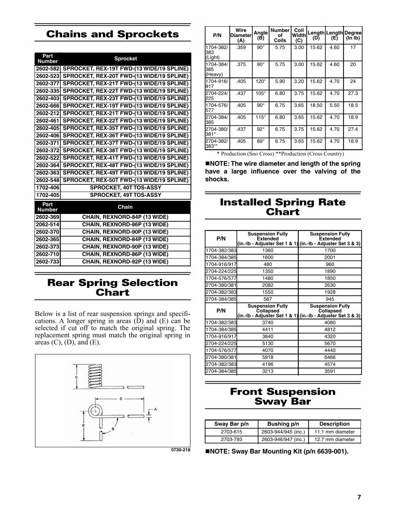
Below is a list of rear suspension springs and specifi-cations. A longer spring in areas (D) and (E) can beselected if cut off to match the original spring. Thereplacement spring must match the original spring inareas (C), (D), and (E).
0730-218
* Production (Sno Cross) **Production (Cross Country)
NOTE: The wire diameter and length of the springhave a large influence over the valving of theshocks.
Installed Spring Rate Chart
Front SuspensionSway Bar
NOTE: Sway Bar Mounting Kit (p/n 6639-001).
PartNumber Sprocket
2602-582 SPROCKET, REX-19T FWD-(13 WIDE/19 SPLINE)2602-523 SPROCKET, REX-20T FWD-(13 WIDE/19 SPLINE)2602-377 SPROCKET, REX-21T FWD-(13 WIDE/19 SPLINE)2602-335 SPROCKET, REX-22T FWD-(13 WIDE/19 SPLINE)2602-403 SPROCKET, REX-23T FWD-(13 WIDE/19 SPLINE)2602-666 SPROCKET, REX-19T FWD-(13 WIDE/19 SPLINE)2602-212 SPROCKET, REX-21T FWD-(13 WIDE/19 SPLINE)2602-461 SPROCKET, REX-22T FWD-(13 WIDE/19 SPLINE)2602-405 SPROCKET, REX-35T FWD-(13 WIDE/19 SPLINE)2602-406 SPROCKET, REX-36T FWD-(13 WIDE/19 SPLINE)2602-371 SPROCKET, REX-37T FWD-(13 WIDE/19 SPLINE)2602-372 SPROCKET, REX-38T FWD-(13 WIDE/19 SPLINE)2602-522 SPROCKET, REX-41T FWD-(13 WIDE/19 SPLINE)2602-364 SPROCKET, REX-48T FWD-(13 WIDE/19 SPLINE)2602-363 SPROCKET, REX-49T FWD-(13 WIDE/19 SPLINE)2602-548 SPROCKET, REX-50T FWD-(13 WIDE/19 SPLINE)1702-406 SPROCKET, 40T TOS-ASSY1702-405 SPROCKET, 49T TOS-ASSY
PartNumber Chain
2602-369 CHAIN, REXNORD-84P (13 WIDE)2062-514 CHAIN, REXNORD-86P (13 WIDE)2602-370 CHAIN, REXNORD-90P (13 WIDE)2602-365 CHAIN, REXNORD-84P (13 WIDE)2602-373 CHAIN, REXNORD-90P (13 WIDE)2602-710 CHAIN, REXNORD-86P (13 WIDE)2602-733 CHAIN, REXNORD-92P (13 WIDE)
P/NWire
Diameter(A)
Angle(B)
Numberof
Coils
CoilWidth
(C)
Length(D)
Length(E)
Degree(In lb)
1704-382/383(Light)
.359 90° 5.75 3.00 15.62 4.60 17
1704-384/385(Heavy)
.375 90° 5.75 3.00 15.62 4.60 20
1704-916/917
.405 120° 5.90 3.20 15.62 4.70 24
2704-224/225
.437 105° 6.80 3.75 15.62 4.70 27.3
1704-576/577
.405 90° 6.75 3.65 18.50 5.50 18.5
2704-384/385
.405 115° 6.80 3.65 15.62 4.70 18.9
2704-380/381*
.437 92° 6.75 3.75 15.62 4.70 27.4
2704-382/383**
.405 89° 6.75 3.65 15.62 4.70 18.9
P/NSuspension Fully
Extended(in.-lb - Adjuster Set 1 & 1)
Suspension FullyExtended
(in.-lb - Adjuster Set 3 & 3)1704-382/383 1360 17001704-384/385 1600 20011704-916/917 480 9602704-224/225 1350 18901704-576/577 1480 18502704-380/381 2082 26302704-382/383 1550 19282704-384/385 567 945
P/NSuspension Fully
Collapsed(in.-lb - Adjuster Set 1 & 1)
Suspension FullyCollapsed
(in.-lb - Adjuster Set 3 & 3)1704-382/383 3740 40801704-384/385 4411 48121704-916/917 3840 43202704-224/225 5130 56701704-576/577 4070 44402704-380/381 5918 64662704-382/383 4196 45742704-384/385 3213 3591
Sway Bar p/n Bushing p/n Description2703-615 2603-944/945 (inc.) 11.1 mm diameter
2703-793 2603-946/947 (inc.) 12.7 mm diameter
7

Rebuildable Shock Tools Required
Optional Front Arm Shock Springs
* Stock Spring
P/N Tool0744-020 Inflation Needle
0644-486 Gas Shock Retaining Blocks
0644-544 Replacement Needle
0644-169 Piston Location Tool
0644-151 Nitrogen Regulator
0644-268 Bearing Cap Seal Protector
0644-403 Bearing Cap Seal Protector (1/2-in. O.D. x 3/8 in. I.D.)
0644-404 Bearing Cap Seal Protector (5/8-in. O.D. x 3/8 in. I.D.)
0644-542 Bearing Cap Seal Protector (5/8 in. O.D. x 1/2 in. I.D.)
0644-543 Gas Shock Shaft Clamping Tool
0644-350 Floating Piston Location Gauge
0644-539 Inflation Needle Replacement Tip
0744-072 Float Shock Spanner Wrench
0644-584 Air Sleeve Bushing Installation Tool
0644-585 Air Sleeve Bushing Installation Tool
0644-456 Bullet Air Sleeve Bushing Installation Tool
P/N LB Length (Inches)2704-755* 100/250 7.75
2704-228 100/250 7.75
2704-229 160/260 7.75
1704-819 230 7.50
1704-820 170 7.50
1704-821 190 7.50
1704-822 210 7.50
1704-831 250 7.50
Ice Racing Springs2704-749 70 6
2704-750 90 6
2704-751 110 6
8

Valve Stacks/Specifications
CD Knob @ 12 clicks from full closed; RB Knob @ 12 clicks from full closed.
Eyelets tightened to 3.9 kg-m (28 ft-lb). Piston nut tightened to 3.0 kg-m (22 ft-lb).
Tighten the shaft nut to 3.0 kg-m (22 ft-lb). Shocks charged at 250 psi (nitrogen)/80/200 psi (air).
Green Loctite #620 on shock eyelet threads.
Compression @ 12 clicks counterclockwise from full stop.
Eyelets tightened to 3.9 kg-m (28 ft-lb). Piston nut tightened to 3.0 kg-m (22 ft-lb). Tighten shaft nut to 3.9 kg-m (28 ft-lb). Shock
charged at 250 psi. Green Loctite #620 on shock eyelet threads.
CD Knob @ 12 clicks from full closed; RB Knob @ 5 clicks counterclockwise.
Shock charged at 250 psi. Green Loctite #620 on shock eyelet threads.
Eyelets tightened to 3.9 kg-m (28 ft-lb). Piston nut tightened to 3.0 kg-m (22 ft-lb).
Tighten the shaft nut to 3.9 kg-m (28 ft-lb).
Part Number Description Compression (Piston Side) Rebound (Piston Side)3703-346/347 Ski Shock 1.300 x 0.008 in. 1.100 x 0.008 in.Extended Length: 18.94 in. Rebuild Kit - p/n 2603-929 1.300 x 0.008 in. 0.800 x 0.004 in.Collapsed Length: 13.29 in. Rebuild Kit - p/n 3604-539 0.800 x 0.006 in. 1.125 x 0.080 in.
GroundStroke: 5.65 in. (Reservoir) 1.300 x 0.010 in.1.250 x 0.010 in. 0.620 x 0.093 in.
Backup1.100 x 0.010 in.1.000 x 0.010 in.0.900 x 0.010 in.
Piston Orifice: 0.059 in. Piston Depth: 2.50 in. 1.125 x 0.093 in. Top out
Compression (CD Piston)0.700 x 0.010 in.0.700 x 0.010 in.0.600 x 0.010 in.0.500 x 0.006 in.
0.400 x 0.020 in. (BU)0.400 x 0.020 in. (BU)
Part Number Description Compression(Piston Side)
Rebound(Piston Side)
2704-635 Front Arm Shock 1.300 x 0.008 in. 1.100 x 0.008 in.Extended Length: 12.36 in. Rebuild Kit - p/n 3604-538 1.300 x 0.008 in. 0.600 x 0.004 in.Collapsed Length: 8.56 in. Rebuild Kit - p/n 4604-017 0.800 x 0.004 in. (Center) 0.700 x 0.010 in.Stroke: 3.80 in. (Reservoir) 1.300 x 0.10 (Ring) 1.125 x 0.080 in.
(Top Out)1.100 x 0.004 in.1.000 x 0.004 in. 0.620 x 0.093 in.
Backup1.000 x 0.004 in.0.700 x 0.004 in.
1.250 x 0.093 in. (Top Out)
Piston Orifice: None Piston Depth: 1.80 in.
Part Number Description Compression(Piston Side)
Rebound(Piston Side)
2704-636 Rear Arm Shock 1.600 x 0.004 in. (DB) 1.425 x 0.015 in.Extended Length: 14.59 in. Rebuild Kit - p/n 2603-013 1.600 x 0.010 in. 1.425 x 0.015 in.
1.600 x 0.010 in. 1.425 x 0.012 in.1.100 x 0.006 in. 1.350 x 0.012 in.
Collapsed Length: 10.06 in. Rebuild Kit - p/n 4604-017 1.600 x 0.012 in. 1.100 x 0.012 in.Stroke: 4.53 in. (Reservoir) 1.600 x 0.012 in. 0.950 x 0.012 in.
1.600 x 0.012 in. 0.800 x 0.020 in.
1.425 x 0.010 in. 0.800 x 0.020 in.1.350 x 0.010 in. 0.750 x 0.080 in.1.100 x 0.008 in. 0.750 x 0.100 in. (Backup)
1.570 x 0.128 in. (Top Out)Piston Orifice: None Piston Depth: 2.40 in.
9

Rebuildable Shock Accessory Part Numbers
NOTE: When rebuilding Fox shocks, use onlyFox valves and/or pistons.
NOTE: Shock Oil (p/n 5639-530) is available fromArctic Cat Service Department.
AC PN Description2603-499 Valve: [0.500 OD X 0.252 ID X 0.006 TH]
2603-500 Valve: [0.600 OD X 0.252 ID X 0.010 TH]
2603-501 Valve: [0.700 OD X 0.252 ID X 0.010 TH]
2603-902 Valve: [0.550 OD X 0.377 ID X 0.020 TH]
3604-171 Valve: [0.600 OD X 0.377 ID X 0.004 TH]
3604-533 Valve: [0.600 OD X 0.377 ID X 0.012 TH]
2603-224 Valve: [0.620 OD X 0.377 ID X 0.015 TH]
0603-731 Valve: [0.700 OD X 0.377 ID X 0.004 TH]
0603-330 Valve: [0.700 OD X 0.377 ID X 0.006 TH]
0603-331 Valve: [0.700 OD X 0.377 ID X 0.008 TH]
0603-332 Valve: [0.700 OD X 0.377 ID X 0.010 TH]
0603-878 Valve: [0.700 OD X 0.377 ID X 0.012 TH]
0603-884 Valve: [0.700 OD X 0.377 ID X 0.015 TH]
0603-895 Valve: [0.800 OD X 0.377 ID X 0.004 TH]
0603-333 Valve: [0.800 OD X 0.377 ID X 0.006 TH]
0603-334 Valve: [0.800 OD X 0.377 ID X 0.008 TH]
0603-335 Valve: [0.800 OD X 0.377 ID X 0.010 TH]
0603-879 Valve: [0.800 OD X 0.377 ID X 0.012 TH]
0603-885 Valve: [0.800 OD X 0.377 ID X 0.015 TH]
0603-894 Valve: [0.900 OD X 0.377 ID X 0.004 TH]
0603-336 Valve: [0.900 OD X 0.377 ID X 0.006 TH]
0603-337 Valve: [0.900 OD X 0.377 ID X 0.008 TH]
0603-338 Valve: [0.900 OD X 0.377 ID X 0.010 TH]
0603-880 Valve: [0.900 OD X 0.377 ID X 0.012 TH]
0603-886 Valve: [0.900 OD X 0.377 ID X 0.015 TH]
0603-893 Valve: [1.000 OD X 0.377 ID X 0.004 TH]
0603-339 Valve: [1.000 OD X 0.377 ID X 0.006 TH]
0603-340 Valve: [1.000 OD X 0.377 ID X 0.008 TH]
0603-341 Valve: [1.000 OD X 0.377 ID X 0.010 TH]
0603-881 Valve: [1.000 OD X 0.377 ID X 0.012 TH]
0603-887 Valve: [1.000 OD X 0.377 ID X 0.015 TH]
0603-892 Valve: [1.100 OD X 0.377 ID X 0.004 TH]
0603-342 Valve: [1.100 OD X 0.377 ID X 0.006 TH]
0603-343 Valve: [1.100 OD X 0.377 ID X 0.008 TH]
0603-344 Valve: [1.100 OD X 0.377 ID X 0.010 TH]
0603-882 Valve: [1.100 OD X 0.377 ID X 0.012 TH]
0603-888 Valve: [1.100 OD X 0.377 ID X 0.015 TH]
0603-345 Valve: [1.250 OD X 0.377 ID X 0.006 TH]
0603-346 Valve: [1.250 OD X 0.377 ID X 0.008 TH]
0603-347 Valve: [1.250 OD X 0.377 ID X 0.010 TH]
0603-883 Valve: [1.250 OD X 0.377 ID X 0.012 TH]
0603-889 Valve: [1.250 OD X 0.377 ID X 0.015 TH]
0603-348 Valve: [1.300 OD X 0.377 ID X 0.006 TH]
0603-349 Valve: [1.300 OD X 0.377 ID X 0.008 TH]
0603-350 Valve: [1.300 OD X 0.377 ID X 0.010 TH]
0603-891 Valve: [1.300 OD X 0.377 ID X 0.012 TH]
0603-890 Valve: [1.300 OD X 0.377 ID X 0.015 TH]
AC PN Description2604-647 Valve: [1.425 OD X 0.377 ID X 0.010 TH]
2604-632 Valve: [1.425 OD X 0.377 ID X 0.012 TH]
2604-633 Valve: [1.425 OD X 0.377 ID X 0.015 TH]
3604-577 Valve: [1.600 OD X 0.377 ID X 0.008 TH]
2604-631 Valve: [1.600 OD X 0.377 ID X 0.010 TH]
2604-683 Valve: [0.650 OD X 0.504 ID X 0.020 TH]
2604-469 Valve: [0.700 OD X 0.504 ID X 0.010 TH]
2604-470 Valve: [0.700 OD X 0.504 ID X 0.020 TH]
2604-471 Valve: [0.750 OD X 0.504 ID X 0.020 TH]
2604-472 Valve: [0.800 OD X 0.504 ID X 0.006 TH]
2604-473 Valve: [0.800 OD X 0.504 ID X 0.008 TH]
2604-474 Valve: [0.800 OD X 0.504 ID X 0.010 TH]
2604-475 Valve: [0.800 OD X 0.504 ID X 0.012 TH]
2604-476 Valve: [0.800 OD X 0.504 ID X 0.015 TH]
2604-477 Valve: [0.800 OD X 0.504 ID X 0.020 TH]
2604-478 Valve: [0.950 OD X 0.504 ID X 0.006 TH]
2604-479 Valve: [0.950 OD X 0.504 ID X 0.008 TH]
2604-480 Valve: [0.950 OD X 0.504 ID X 0.010 TH]
2604-481 Valve: [0.950 OD X 0.504 ID X 0.012 TH]
2604-482 Valve: [0.950 OD X 0.504 ID X 0.015 TH]
2604-483 Valve: [1.000 OD X 0.504 ID X 0.020 TH]
3604-149 Valve: [1.100 OD X 0.504 ID X 0.004 TH]
2604-484 Valve: [1.100 OD X 0.504 ID X 0.006 TH]
2604-485 Valve: [1.100 OD X 0.504 ID X 0.008 TH]
2604-486 Valve: [1.100 OD X 0.504 ID X 0.010 TH]
2604-487 Valve: [1.100 OD X 0.504 ID X 0.012 TH]
2604-488 Valve: [1.100 OD X 0.504 ID X 0.015 TH]
2604-489 Valve: [1.100 OD X 0.504 ID X 0.020 TH]
2604-684 Valve: [1.250 OD X 0.504 ID X 0.006 TH]
2604-685 Valve: [1.250 OD X 0.504 ID X 0.008 TH]
2604-686 Valve: [1.250 OD X 0.504 ID X 0.010 TH]
2604-687 Valve: [1.250 OD X 0.504 ID X 0.012 TH]
2604-688 Valve: [1.250 OD X 0.504 ID X 0.015 TH]
2604-490 Valve: [1.350 OD X 0.504 ID X 0.006 TH]
2604-491 Valve: [1.350 OD X 0.504 ID X 0.008 TH]
2604-492 Valve: [1.350 OD X 0.504 ID X 0.010 TH]
2604-493 Valve: [1.350 OD X 0.504 ID X 0.012 TH]
2604-494 Valve: [1.350 OD X 0.504 ID X 0.015 TH]
2604-495 Valve: [1.425 OD X 0.504 ID X 0.006 TH]
2604-496 Valve: [1.425 OD X 0.504 ID X 0.008 TH]
2604-497 Valve: [1.425 OD X 0.504 ID X 0.010 TH]
2604-498 Valve: [1.425 OD X 0.504 ID X 0.012 TH]
2604-499 Valve: [1.425 OD X 0.504 ID X 0.015 TH]
2604-500 Valve: [1.600 OD X 0.504 ID X 0.006 TH]
2604-501 Valve: [1.600 OD X 0.504 ID X 0.008 TH]
2604-502 Valve: [1.600 OD X 0.504 ID X 0.010 TH]
2604-503 Valve: [1.600 OD X 0.504 ID X 0.012 TH]
2604-504 Valve: [1.600 OD X 0.504 ID X 0.015 TH]
10

Double Bleed Shims (DB)
Single Bleed Shims (DB)
Fraction/Decimal Conversion Chart
Drill Bit Sizes(Number) Chart
AC PN Description3603-342 Valve: DB 3 PORT (1.30" OD X .375" ID .004" THK.)
3603-343 Valve: DB 3 PORT (1.30" OD X .375" ID .006" THK.)
3603-344 Valve: DB 3 PORT (1.30" OD X .375" ID .008" THK.)
3603-345 Valve: DB 3 PORT (1.30" OD X .375" ID .010" THK.)
3603-346 Valve: DB 3 PORT (1.30" OD X .375" ID .012" THK.)
3603-347 Valve: DB 3 PORT (1.30" OD X .375" ID .015" THK.)
3603-348 Valve: DB 3 PORT (1.30" OD X .375" ID .020" THK.)
3603-481 Valve: DB 4 PORT (1.60" OD X .502" ID .004" THK.)
3603-482 Valve: DB 4 PORT (1.60" OD X .502" ID .006" THK.)
3603-483 Valve: DB 4 PORT (1.60" OD X .502" ID .008" THK.)
3603-484 Valve: DB 4 PORT (1.60" OD X .502" ID .010" THK.)
3603-485 Valve: DB 4 PORT (1.60" OD X .502" ID .012" THK.)
3603-486 Valve: DB 4 PORT (1.60" OD X .502" ID .015" THK.)
3603-487 Valve: DB 4 PORT (1.60" OD X .502" ID .020" THK.)
AC PN Description3603-469 Valve: SB 3 PORT (1.30" OD X .375" ID .004" THK.)
3603-470 Valve: SB 3 PORT (1.30" OD X .375" ID .006" THK.)
4604-038 Valve: SB 3 PORT (1.30" OD X .375" ID .008" THK.)
3603-471 Valve: SB 3 PORT (1.30" OD X .375" ID .010" THK.)
3603-472 Valve: SB 3 PORT (1.30" OD X .375" ID .012" THK.)
3603-473 Valve: SB 3 PORT (1.30" OD X .375" ID .015" THK.)
3603-474 Valve: SB 3 PORT (1.30" OD X .375" ID .020" THK.)
3603-475 Valve: SB 4 PORT (1.60" OD X .502" ID .004" THK.)
3603-410 Valve: SB 4 PORT (1.60" OD X .502" ID .006" THK.)
3603-476 Valve: SB 4 PORT (1.60" OD X .502" ID .005" THK.)
3603-477 Valve: SB 4 PORT (1.60" OD X .502" ID .010" THK.)
3603-478 Valve: SB 4 PORT (1.60" OD X .502" ID .012" THK.)
3603-479 Valve: SB 4 PORT (1.60" OD X .502" ID .015" THK.)
3603-480 Valve: SB 4 PORT (1.60" OD X .502" ID .020" THK.)
8ths 16ths 32nds 64ths 64ths (cont)1/8 = .125 1/16 = .0625 1/32 = .03125 1/64 = .015625 33/64 = .5156251/4 = .250 3/16 = .1875 3/32 = .09375 3/64 = .046875 35/64 = .5468753/8 = .375 5/16 = .3125 5/32 = .15625 5/64 = .078125 37/64 = .5781251/2 = .500 7/16 = .4375 7/32 = .21875 7/64 = .109375 39/64 = .6093755/8 = .625 9/16 = .5625 9/32 = .28125 9/64 = .140625 41/64 = .6406253/4 = .750 11/16 = .6875 11/32 = .34375 11/64 = .171875 43/64 = .6718757/8 = .875 13/16 = .8125 13/32 = .40625 13/64 = .203125 45/64 = .703125
— 15/16 = .9375 15/32 = .46875 15/64 = .234370 47/64 = .734375— — 17/32 = .53125 17/64 = .265625 49/64 = .765625— — 19/32 = .59375 19/64 = .296875 51/64 = .796875— — 21/32 = .65625 21/64 = .328125 53/64 = .828125— — 23/32 = .71875 23/64 = .359375 55/64 = .859375— — 25/32 = .78125 25/64 = .390625 57/64 = .890625— — 27/32 = .84375 27/64 = .421875 59/64 = .921875— — 29/32 = .90625 29/64 = .453125 61/64 = .953125— — 31/32 = .96875 31/64 = .484375 63/64 = .984375
No.Size ofDrill inInches
No.Size ofDrill inInches
No.Size ofDrill inInches
No.Size ofDrill inInches
1 .2280 21 .1590 41 .0960 61 .0390
2 .2210 22 .1570 42 .0935 62 .0380
3 .2130 23 .1540 43 .0890 63 .0370
4 .2090 24 .1520 44 .0860 64 .0360
5 .2055 25 .1495 45 .0820 65 .0350
6 .2040 26 .1470 46 .0810 66 .0330
7 .2010 27 .1440 47 .0785 67 .0320
8 .1990 28 .1405 48 .0760 68 .0310
9 .1960 29 .1360 49 .0730 69 .0292
10 .1935 30 .1285 50 .0700 70 .0280
11 .1910 31 .1200 51 .0670 71 .0260
12 .1890 32 .1160 52 .0635 72 .0250
13 .1850 33 .1130 53 .0595 73 .0240
14 .1820 34 .1110 54 .0550 74 .0225
15 .1800 35 .1100 55 .0520 75 .0210
16 .1770 36 .1065 56 .0465 76 .0200
17 .1730 37 .1040 57 .0430 77 .0180
18 .1695 38 .1015 58 .0420 78 .0160
19 .1660 39 .0995 59 .0410 79 .0145
20 .1610 40 .0980 60 .0400 80 .0135
11

MM/IN. Conversion Chart
mm in. mm in. mm in. mm in..01 .00039 .51 .02008 1 .03937 51 2.00787
.02 .00079 .52 .02047 2 .07874 52 2.04724
.03 .00118 .53 .02087 3 .11811 53 2.08661
.04 .00157 .54 .02126 4 .15748 54 2.12598
.05 .00197 .55 .02165 5 .19685 55 2.16535
.06 .00236 .56 .02205 6 .23622 56 2.20472
.07 .00276 .57 .02244 7 .27559 57 2.24409
.08 .00315 .58 .02283 8 .31496 58 2.28346
.09 .00354 .59 .02323 9 .35433 59 2.32283
.10 .00394 .60 .02362 10 .39370 60 2.36220
.11 .00433 .61 .02402 11 .43307 61 2.40157
.12 .00472 .62 .02441 12 .47244 62 2.44094
.13 .00512 .63 .02480 13 .51181 63 2.48031
.14 .00551 .64 .02520 14 .55118 64 2.51968
.15 .00591 .65 .02559 15 .59055 65 2.55905
.16 .00630 .66 .02598 16 .62992 66 2.59842
.17 .00669 .67 .02638 17 .66929 67 2.63779
.18 .00709 .68 .02677 18 .70866 68 2.67716
.19 .00748 .69 .02717 19 .74803 69 2.71653
.20 .00787 .70 .02756 20 .78740 70 2.75590
.21 .00827 .71 .02795 21 .82677 71 2.79527
.22 .00866 .72 .02835 22 .86614 72 2.83464
.23 .00906 .73 .02874 23 .90551 73 2.87401
.24 .00945 .74 .02913 24 .94488 74 2.91338
.25 .00984 .75 .02953 25 .98425 75 2.95275
.26 .01024 .76 .02992 26 1.02362 76 2.99212
.27 .01063 .77 .03032 27 1.06299 77 3.03149
.28 .01102 .78 .03071 28 1.10236 78 3.07086
.29 .01142 .79 .03110 29 1.14173 79 3.11023
.30 .01181 .80 .03150 30 1.18110 80 3.14960
.31 .01220 .81 .03189 31 1.22047 81 3.18897
.32 .01260 .82 .03228 32 1.25984 82 3.22834
.33 .01299 .83 .03268 33 1.29921 83 3.26771
.34 .01339 .84 .03307 34 1.33858 84 3.30708
.35 .01378 .85 .03346 35 1.37795 85 3.34645
.36 .01417 .86 .03386 36 1.41732 86 3.38582
.37 .01457 .87 .03425 37 1.45669 87 3.42519
.38 .01496 .88 .03465 38 1.49606 88 3.46456
.39 .01535 .89 .03504 39 1.53543 89 3.50393
.40 .01575 .90 .03543 40 1.57480 90 3.54330
.41 .01614 .91 .03583 41 1.61417 91 3.58267
.42 .01654 .92 .03622 42 1.65354 92 3.62204
.43 .01693 .93 .03661 43 1.69291 93 3.66141
.44 .01732 .94 .03701 44 1.73228 94 3.70078
.45 .01772 .95 .03740 45 1.77165 95 3.74015
.46 .01811 .96 .03780 46 1.81102 96 3.77952
.47 .01850 .97 .03819 47 1.85039 97 3.81889
.48 .01890 .98 .03858 48 1.88976 98 3.85826
.49 .01929 .99 .03898 49 1.92913 99 3.89763
.50 .01969 1.0 .03937 50 1.96850 100 3.93700
12

Wiring Diagram - Hood Harness
(p/n 1686-706) - Cross Country
0748-009
13

NOTES
14

Wiring Diagram (Ignition/Main)(Harness p/n 1686-732)
0747-813
15

16
Setup Instructions
This snowmobile has been prepared at the factory tominimize required setup items; however, there aresome items and inspections that must be done at adealership or by the owner/operator. Please pay closeattention to all items on the following pages. Be sure toread these instructions thoroughly before starting to setup the snowmobile.
Removing Snowmobile From Crate/Handlebar Assembly
1. Remove the top and four sides of the crate.Remove the skis from the crate sides.
2. Remove the windshield and hardware kit.
3. Remove all mounting hardware securing thesnowmobile to the crate base; then lift the snow-mobile free of the crate base.
4. Swing the handlebar up and tighten the cap screwsevenly to 15 ft-lb; then check steering for maxi-mum right/left turning capabilities. Install the han-dlebar pad assembly.
Installing Windshield
1. Remove the protective film from the windshield.
2. Install the expansion nuts into the speedometerbracket; then place the windshield into position onthe console and bracket.
SNO-490
3. Secure the windshield using the screws according tothe illustration.
Installing Spindle/A-Arm
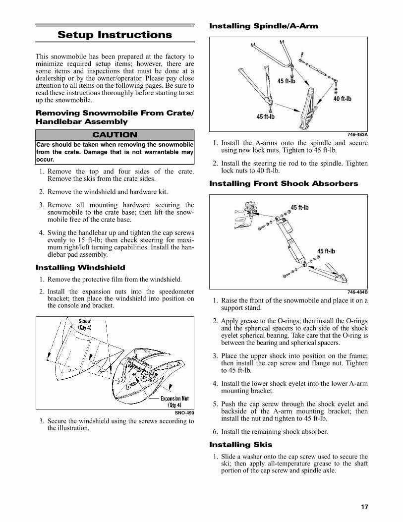
746-483A
1. Install the A-arms onto the spindle and secureusing new lock nuts. Tighten to 45 ft-lb.
2. Install the steering tie rod to the spindle. Tightenlock nuts to 40 ft-lb.
Installing Front Shock Absorbers
746-484B
1. Raise the front of the snowmobile and place it on asupport stand.
2. Apply grease to the O-rings; then install the O-ringsand the spherical spacers to each side of the shockeyelet spherical bearing. Take care that the O-ring isbetween the bearing and spherical spacers.
3. Place the upper shock into position on the frame;then install the cap screw and flange nut. Tightento 45 ft-lb.
4. Install the lower shock eyelet into the lower A-armmounting bracket.
5. Push the cap screw through the shock eyelet andbackside of the A-arm mounting bracket; theninstall the nut and tighten to 45 ft-lb.
6. Install the remaining shock absorber.
Installing Skis
1. Slide a washer onto the cap screw used to secure theski; then apply all-temperature grease to the shaftportion of the cap screw and spindle axle.
CAUTIONCare should be taken when removing the snowmobilefrom the crate. Damage that is not warrantable mayoccur.
17

0747-094
2. Install the spindle axle into the spindle; then position theski damper into the bottom of the ski making sure thedamper is properly positioned for the desired ski stance.
NOTE: The ski damper must be positioned in the skiso it is directly under the spindle.
3. With the cap screw hole of the ski centered with thespindle axle, slide the cap screw with washer throughthe outside of the ski and spindle assemblies.
NOTE: Local laws and/or regulations as to maxi-mum width of the ski stance may be applicable.Always comply with the maximum width laws and/orregulations when adjusting ski stance.
NOTE: Install the cap screw so the lock nut will belocated to the inside of the ski and the cotter pin slotin the cap screw will be horizontal with the ski.
4. Install the remaining washer and lock nut; thentighten the lock nut to 35 ft-lb.
NOTE: Assure that the cotter pin slot in the capscrew is still horizontal with the ski (see illustration);then proceed to step 7.
5. Install the cotter pin from the back side of the ski capscrew and spread the pin.
NOTE: Repeat this sub-section on the opposite side.
Sway Bar
SNO-2232
1. Place the sway bar into position (mounting loca-tion) of the chassis.
2. Secure the bar with the two mounting brackets,four machine screws.
3. Tighten machine screws evenly to 8 ft-lb.
4. Position the sway bar link onto the lower A-armand the sway bar. Install the cap screws and locknuts. Tighten the lock nuts to 23 ft-lb.
Brake System
Checking Brake Fluid
1. With the brake fluid reservoir in a level position,check the fluid level. The brake fluid level must bejust below the high mark.
SNO-253
2. If the brake fluid level is below the low mark,remove the reservoir cover and add Arctic Catapproved brake fluid until the fluid level is justbelow the high mark. Install and secure the reser-voir cover. Do not allow moisture to contaminatethe brake system.
Checking Brake Lever Operation
1. Test the operation of the hydraulic brake systemby compressing the brake lever.
2. The brake lever must feel firm when compressed.
Ski Alignment
Checking
NOTE: Track tension and alignment must be properlyadjusted prior to checking or adjusting ski alignment.Ski alignment must be performed on a flat, level sur-face. Ski toe-out must fall within the specified range.
1. Raise the front end of snowmobile just highenough that the ski shocks are fully extended butthe skis are still resting on the floor.
CAUTIONBrake fluid is highly corrosive. Do not spill brake fluidon any surface of the snowmobile.
! WARNINGDo not overfill the brake fluid reservoir. Overfilling thereservoir may cause the brake system to hydraulicallylock. Use only Arctic Cat approved brake fluid.
Toe-Out Range0.0 - 12.7 mm (0 - 1/2 in.)
18
2. From the riding position on the snowmobile,check that the handlebar is in a straight-forwarddirection for driving.
NOTE: Steering can be centered in the chassis bytaking measurements from each side of the draglink to a location on the chassis which would be ofequal distance from each side of the drag link.
3. Using a very light hold-down strap (bungee cord)between the ski handles, apply a very light loadapproximately 2-4 lb pulling the skis together justenough to pull the slack.
NOTE: Track tension and alignment must beproperly adjusted prior to placing the straightedgeagainst the outside edge of the track.
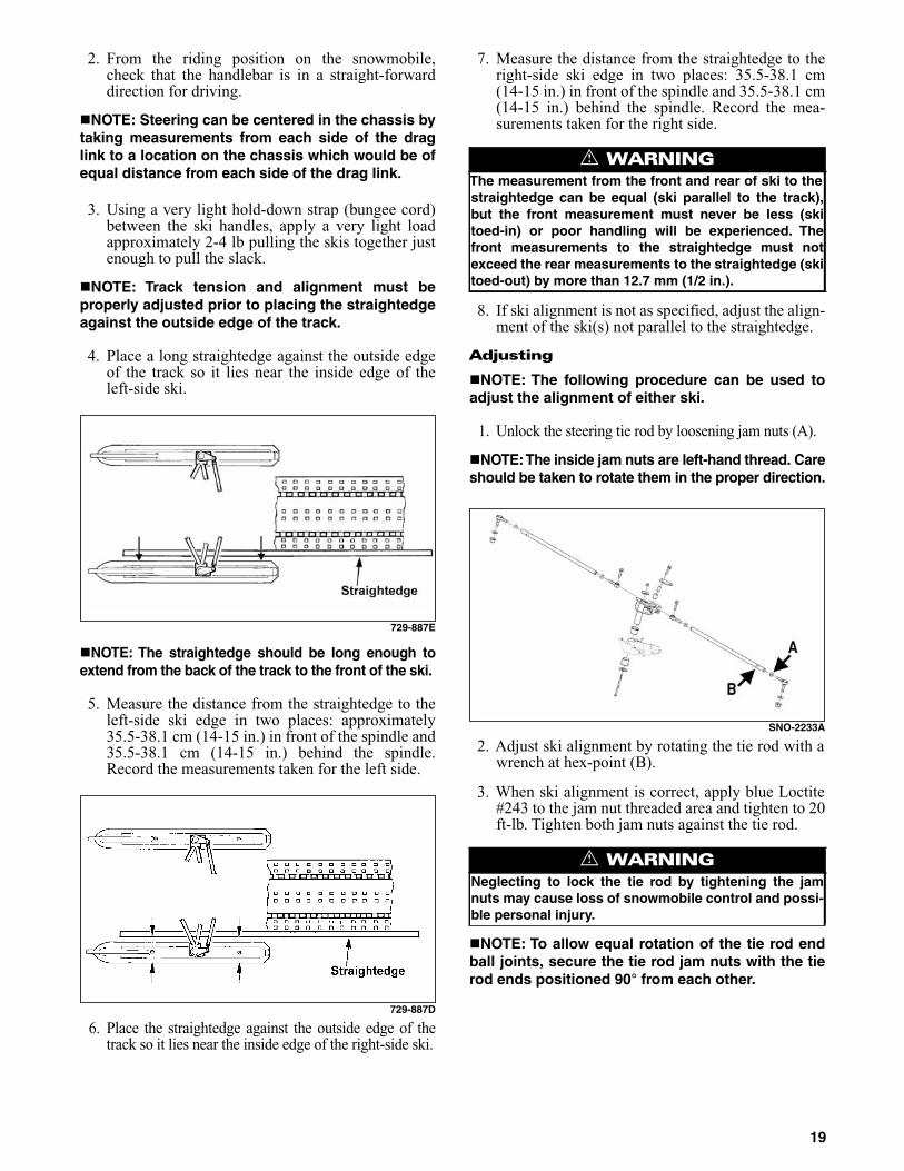
4. Place a long straightedge against the outside edgeof the track so it lies near the inside edge of theleft-side ski.
729-887E
NOTE: The straightedge should be long enough toextend from the back of the track to the front of the ski.
5. Measure the distance from the straightedge to theleft-side ski edge in two places: approximately35.5-38.1 cm (14-15 in.) in front of the spindle and35.5-38.1 cm (14-15 in.) behind the spindle.Record the measurements taken for the left side.
729-887D
6. Place the straightedge against the outside edge of thetrack so it lies near the inside edge of the right-side ski.
7. Measure the distance from the straightedge to theright-side ski edge in two places: 35.5-38.1 cm(14-15 in.) in front of the spindle and 35.5-38.1 cm(14-15 in.) behind the spindle. Record the mea-surements taken for the right side.
8. If ski alignment is not as specified, adjust the align-ment of the ski(s) not parallel to the straightedge.
Adjusting
NOTE: The following procedure can be used toadjust the alignment of either ski.
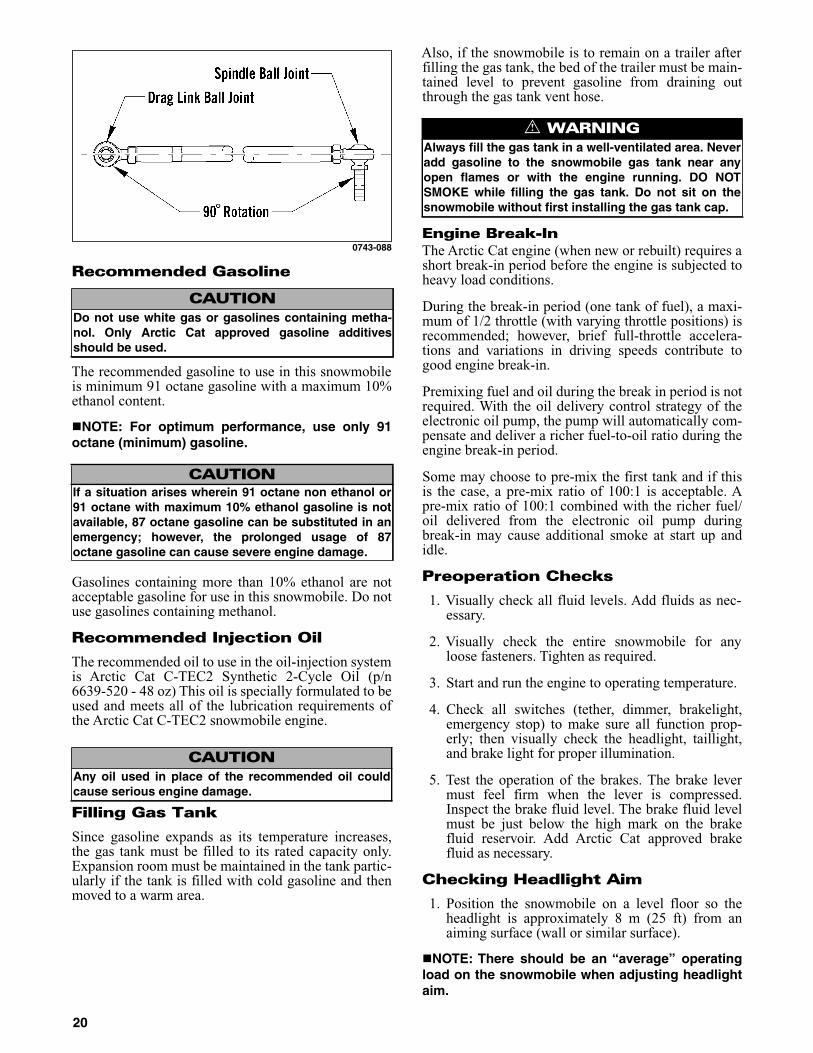
1. Unlock the steering tie rod by loosening jam nuts (A).
NOTE:The inside jam nuts are left-hand thread. Careshould be taken to rotate them in the proper direction.
SNO-2233A
2. Adjust ski alignment by rotating the tie rod with awrench at hex-point (B).
3. When ski alignment is correct, apply blue Loctite#243 to the jam nut threaded area and tighten to 20ft-lb. Tighten both jam nuts against the tie rod.
NOTE: To allow equal rotation of the tie rod endball joints, secure the tie rod jam nuts with the tierod ends positioned 90° from each other.
! WARNINGThe measurement from the front and rear of ski to thestraightedge can be equal (ski parallel to the track),but the front measurement must never be less (skitoed-in) or poor handling will be experienced. Thefront measurements to the straightedge must notexceed the rear measurements to the straightedge (skitoed-out) by more than 12.7 mm (1/2 in.).
! WARNINGNeglecting to lock the tie rod by tightening the jamnuts may cause loss of snowmobile control and possi-ble personal injury.
19
0743-088
Recommended Gasoline
The recommended gasoline to use in this snowmobileis minimum 91 octane gasoline with a maximum 10%ethanol content.
NOTE: For optimum performance, use only 91octane (minimum) gasoline.
Gasolines containing more than 10% ethanol are notacceptable gasoline for use in this snowmobile. Do notuse gasolines containing methanol.
Recommended Injection Oil
The recommended oil to use in the oil-injection systemis Arctic Cat C-TEC2 Synthetic 2-Cycle Oil (p/n6639-520 - 48 oz) This oil is specially formulated to beused and meets all of the lubrication requirements ofthe Arctic Cat C-TEC2 snowmobile engine.
Filling Gas Tank
Since gasoline expands as its temperature increases,the gas tank must be filled to its rated capacity only.Expansion room must be maintained in the tank partic-ularly if the tank is filled with cold gasoline and thenmoved to a warm area.
Also, if the snowmobile is to remain on a trailer afterfilling the gas tank, the bed of the trailer must be main-tained level to prevent gasoline from draining outthrough the gas tank vent hose.
Engine Break-InThe Arctic Cat engine (when new or rebuilt) requires ashort break-in period before the engine is subjected toheavy load conditions.
During the break-in period (one tank of fuel), a maxi-mum of 1/2 throttle (with varying throttle positions) isrecommended; however, brief full-throttle accelera-tions and variations in driving speeds contribute togood engine break-in.
Premixing fuel and oil during the break in period is notrequired. With the oil delivery control strategy of theelectronic oil pump, the pump will automatically com-pensate and deliver a richer fuel-to-oil ratio during theengine break-in period.
Some may choose to pre-mix the first tank and if thisis the case, a pre-mix ratio of 100:1 is acceptable. Apre-mix ratio of 100:1 combined with the richer fuel/oil delivered from the electronic oil pump duringbreak-in may cause additional smoke at start up andidle.
Preoperation Checks
1. Visually check all fluid levels. Add fluids as nec-essary.
2. Visually check the entire snowmobile for anyloose fasteners. Tighten as required.
3. Start and run the engine to operating temperature.
4. Check all switches (tether, dimmer, brakelight,emergency stop) to make sure all function prop-erly; then visually check the headlight, taillight,and brake light for proper illumination.
5. Test the operation of the brakes. The brake levermust feel firm when the lever is compressed.Inspect the brake fluid level. The brake fluid levelmust be just below the high mark on the brakefluid reservoir. Add Arctic Cat approved brakefluid as necessary.
Checking Headlight Aim
1. Position the snowmobile on a level floor so theheadlight is approximately 8 m (25 ft) from anaiming surface (wall or similar surface).
NOTE: There should be an “average” operatingload on the snowmobile when adjusting headlightaim.
CAUTIONDo not use white gas or gasolines containing metha-nol. Only Arctic Cat approved gasoline additivesshould be used.
CAUTIONIf a situation arises wherein 91 octane non ethanol or91 octane with maximum 10% ethanol gasoline is notavailable, 87 octane gasoline can be substituted in anemergency; however, the prolonged usage of 87octane gasoline can cause severe engine damage.
CAUTIONAny oil used in place of the recommended oil couldcause serious engine damage.
! WARNINGAlways fill the gas tank in a well-ventilated area. Neveradd gasoline to the snowmobile gas tank near anyopen flames or with the engine running. DO NOTSMOKE while filling the gas tank. Do not sit on thesnowmobile without first installing the gas tank cap.
20

2. Measure the distance from the floor to midpoint ofthe headlight.
3. Using the measurement obtained in step 2, make ahorizontal mark on the aiming surface.
4. Make a vertical mark which intersects the horizon-tal mark on the aiming surface directly in front ofthe headlight.
5. Engage the brake lever lock and start the engine.Move the headlight dimmer switch to the HIGHbeam position. DO NOT USE LOW BEAM.
6. Observe the headlight beam aim. Proper aim iswhen the most intense beam is centered on the ver-tical mark 5 cm (2 in.) below the horizontal markon the aiming surface.
0745-813
7. Adjust the headlight adjustment knobs until cor-rect aim is obtained. Shut the engine off; then dis-engage the brake lever lock.
Track Tension/Track Alignment
To adjust track tension/track alignment, use the fol-lowing procedure.
1. Elevate the snowmobile on a shielded safety standhigh enough to use a spring scale.
2. At mid-point of the track (on the bottom side),hook a spring scale around a track clip; then pulldown on the scale to 9 kg (20 lb). Measure thedeflection (distance) between the bottom of thewear strip and the inside surface of the track clip.Compare the measurement with the chart.
0744-068
3. Using Axle Nut Spanner Wrench (p/n 0644-558)from the tool kit, loosen the right-side rear axle nut.
0744-067
NOTE: Always loosen the right-side rear axle nutwhen adjusting track tension/alignment. The left-side rear axle nut is secured with green Loctite#609 and should not be loosened or removed.
4. If the distance between the bottom of the wearstrip and the inside surface of the track clipexceeds specifications, tighten the adjusting bolts.If the distance between the bottom of the wearstrip and inside surface of the track clip is less thanspecified, loosen the adjusting bolts.
5. When proper track deflection is attained, loosenthe right-side rear axle nut just enough to applyblue Loctite #243 to the axle threads; then tightenthe nut to 40-45 ft-lb.
CAUTIONTrack tension has been initially adjusted at the factoryfor “run-up testing”; however, track tension (and trackalignment) must be adjusted at the dealership accord-ing to the following recommendations.
! WARNINGThe tips of the skis must be positioned against a wallor similar object for safety.
Rear Suspension Style SetupTension
After Break-InTension
129 in. Track @ 20 lb 35-41 mm(1 3/8-1 5/8 in.)
38-44 mm(1 1/2-1 3/4 in.)
CAUTIONMake certain the right-side rear axle nut is tightenedor component damage will occur.
21
6. Start the engine and accelerate slightly. Use onlyenough throttle to turn the track several revolu-tions. Shut engine off.
NOTE: Allow the track to coast to a stop. Do notapply the brake because it could produce an inac-curate alignment condition.
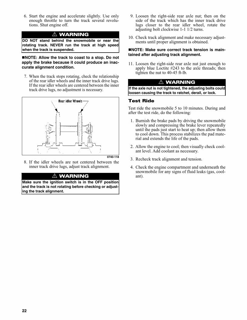
7. When the track stops rotating, check the relationshipof the rear idler wheels and the inner track drive lugs.If the rear idler wheels are centered between the innertrack drive lugs, no adjustment is necessary.
0740-118
8. If the idler wheels are not centered between theinner track drive lugs, adjust track alignment.
9. Loosen the right-side rear axle nut; then on theside of the track which has the inner track drivelugs closer to the rear idler wheel, rotate theadjusting bolt clockwise 1-1 1/2 turns.
10. Check track alignment and make necessary adjust-ments until proper alignment is obtained.
NOTE: Make sure correct track tension is main-tained after adjusting track alignment.
11. Loosen the right-side rear axle nut just enough toapply blue Loctite #243 to the axle threads; thentighten the nut to 40-45 ft-lb.
Test Ride
Test ride the snowmobile 5 to 10 minutes. During andafter the test ride, do the following:
1. Burnish the brake pads by driving the snowmobileslowly and compressing the brake lever repeatedlyuntil the pads just start to heat up; then allow themto cool down. This process stabilizes the pad mate-rial and extends the life of the pads.
2. Allow the engine to cool; then visually check cool-ant level. Add coolant as necessary.
3. Recheck track alignment and tension.
4. Check the engine compartment and underneath thesnowmobile for any signs of fluid leaks (gas, cool-ant).
! WARNINGDO NOT stand behind the snowmobile or near therotating track. NEVER run the track at high speedwhen the track is suspended.
! WARNINGMake sure the ignition switch is in the OFF positionand the track is not rotating before checking or adjust-ing the track alignment.
! WARNINGIf the axle nut is not tightened, the adjusting bolts couldloosen causing the track to ratchet, derail, or lock.
22

General Information
Control Locations
0746-486
Arctic Power Valve (APV) System
This RPM and exhaust pipe temperature controlledservomotor (servo) actuation system adjusts the size ofthe exhaust ports to provide peak performancethroughout the RPM range.
At low RPM, the exhaust valves are held in theDOWN position by return springs. This gives theengine a “low port” exhaust design calibrated to pro-vide maximum low RPM power.
739-152A
At high RPM, the exhaust valves are raised. This cre-ates a “high port” exhaust design calibrated to providemaximum performance at high RPM.
739-152B
To adjust the APV system, use the following proce-dure:
1. Remove the actuating cables from the servo.
2. While holding the cable housing, lightly pull onone cable end to remove slack.
3. Measure the amount of exposed cable from thecable housing to the end of the cable.
0735-516
4. Repeat steps 2 and 3 on the other cable; then com-pare the measurements.
NOTE: Measurements must be within a range of36.5 mm ± 1 mm.
NOTE: The measurements must be equal andwithin the specifications. If the measurements arewithin specifications, no adjustment is necessary.If they are not within specifications, proceed tostep 5.
5. Loosen the jam nut on the cable adjuster to beadjusted; then using the adjusting nuts, lengthen orshorten the housing as needed.
6. While holding the adjusting nut in place, tightenthe jam nut securely.
7. Install the actuating cables to the servo.
Exhaust Controlled Timing (ECT) System
This system automatically adjusts the ignition timingto provide maximum performance through a variety ofoperating conditions. The ECM unit receives input onengine RPM (demand) and exhaust pipe temperature(engine condition) and adjusts the ignition timingaccordingly. This system is not adjustable and is main-tenance free.
If a system fault is suspected, disconnect the exhaustpipe temperature sensor; then use an ohmmeter tocheck continuity of the exhaust pipe temperature sen-sor located in the expansion chamber. A reading ofeither 0 ohm or infinity indicates a failed sensor.
CAUTIONIf excessive adjustment is required to attain synchro-nization, the entire adjustment procedure should berepeated.
23

NOTE: A disabled ECT system WILL NOT causeengine damage; however, a failed ECT system willhave slower throttle response and may produceslightly less top-end performance.
Testing Exhaust Temperature Sensor
1. Disconnect the sensor harness; then remove thesensor from the exhaust pipe.
2. Suspend the sensor (only up to the threads) in acontainer filled with automatic transmission oil;then slowly heat the oil on a hot plate.
3. Using a fluid thermometer, closely monitor the oiltemperature, and using a digital multimeter withthe leads connected to the sensor leads, observethe resistance reading.
4. The resistance must be within the temperaturerange (see chart).
5. If the resistance and temperature are not withinspecifications, replace the sensor.
NOTE: Before replacing the sensor, repeat thetest to confirm results.
Handlebar Tilt
The handlebar can be adjusted to the operator’s prefer-ence. To adjust the handlebar, use the following proce-dure:
1. Loosen the eight cap screws securing the handlebarcaps to the riser and the riser to the steering post.
SNO-2236
2. Adjust the handlebar up or down to operator’sdesired tilt, tighten the cap screws evenly to 15 ft-lb, and check steering for maximum right/left turn-ing capabilities.
NOTE: Do not adjust the handlebar to a positionthat allows the brake fluid to be below the lowmark on either side of the master cylinder.
Rear Bumper
The rear bumper can be removed and replaced. To remove/install a rear bumper, use the following procedure.
1. On the inside of the tunnel, drill out all rivets andremove both screws and nuts securing the rearbumper to both sides of the tunnel.
2. Remove the existing bumper and install the newone aligning the holes with the holes in the brack-ets; then rivet the rear bumper to both sides of thetunnel. Secure the front of the bumper using theexisting machine screws and nuts.
Exhaust System
The exhaust system is designed to reduce noise and toimprove the total performance of the engine. If anyexhaust system component is removed from the engineand the engine is run, severe engine damage will result.
Liquid Cooling System
The cooling system should be inspected daily for leak-age and damage. Also, the coolant level should bechecked daily. If leakage or damage is detected and theoperator does not feel qualified to service the coolingsystem, see an authorized Arctic Cat Snowmobiledealer for this service.
When filling the cooling system, use a coolant/watermixture which will satisfy the coldest anticipatedweather conditions of your area in accordance with thecoolant manufacturer’s recommendations. While thecooling system is being filled, air pockets maydevelop; therefore, fill the bottle and run the engine forfive to ten minutes after the initial fill (until the ther-mostat opens); then add more coolant if necessary. Fillthe coolant tank and take the snowmobile for a testride. Let the engine cool down; then recheck the cool-ant level and add if necessary.
NOTE: Use a good quality, glycol-based, automo-tive-type antifreeze.
Exhaust Temperature Sensor° F ° C ohms
77 25 219.6
122 50 238.5
212 100 275.9
302 150 312.7
! WARNINGTighten cap screws according to specifications to pre-vent unexpected “fold-down” of the handlebar duringoperation over rough terrain. DO NOT offset the han-dlebar so steering capabilities are altered or throttleand brake controls will be affected.
CAUTIONAfter operating the snowmobile for the initial 5-10 min-utes, stop the engine, allow the engine to cool down,and check the coolant level. Add coolant as neces-sary.
24

Drive Clutch And Driven Clutch
The drive clutch and driven clutch do not require lubri-cation; therefore, no special maintenance is requiredby the snowmobile owner. However, the drive clutchand driven clutch should be disassembled, cleaned,and inspected before each race.
NOTE: A small amount of grease should beapplied to the driven shaft before installing thedriven clutch.
When operating the snowmobile at high altitudes, itmay be necessary to change certain component partsof the drive clutch. If the operator does not feel quali-fied to change clutch components, see an authorizedArctic Cat Snowmobile dealer for this service.
Drive Clutch/Driven Clutch Alignment
The parallelism and the offset between the drive clutchand driven clutch are set at the factory. Normally, noadjustment is necessary as long as neither the driveclutch nor the driven clutch is removed or disassem-bled. However, if premature drive belt wear is experi-enced or if the drive belt turns over, the drive clutch/driven clutch alignment must be checked. If the opera-tor does not feel qualified to align the clutch/clutch,see an authorized Arctic Cat Snowmobile dealer forthis service.
Shock Absorbers
Each shock absorber should be visibly checked daily forexcessive fluid leakage, cracks or breaks in the lowercase, a bent plunger, and wear or leakage in the hoses. Ifany one of these conditions is detected, replacement isnecessary. If the operator does not feel qualified to ser-vice or replace shock absorbers, see an authorized Arc-tic Cat Snowmobile dealer for this service.
Track Studs
NOTE: The track on this snowmobile is notequipped with studs. For additional information,see the 2015 POGA Reference Guide.
The decision to install studs should be made only afterreviewing the International Snowmobile Racing, Inc.regulations as they pertain to the type of racing youparticipate in. Arctic Cat has a variety of studdingproducts available from your authorized Arctic CatSnowmobile dealer.
Towing
If this snowmobile is to be towed by another snowmo-bile, do not tow using the loops in the skis. The towrope should be attached to the lower A-arms.
CAUTIONUse Clutch Puller (p/n 0744-062). Never substitute adifferent puller or drive clutch damage will occur.
25
Operating Instructions
Starting And Stopping Engine
It is imperative that the hydraulic brake system bechecked for wear and proper operation and that allsafety checks found in the accompanying SnowmobileSafety Handbook be performed before attempting tostart the engine. After the engine has been started,check the headlights (high and low beam), taillight,and brakelight to be sure they are working properlyand adjusted correctly. Make sure all lights are clean toprovide maximum illumination. The headlight andtaillight must be clean and must be illuminated when-ever the engine is running.
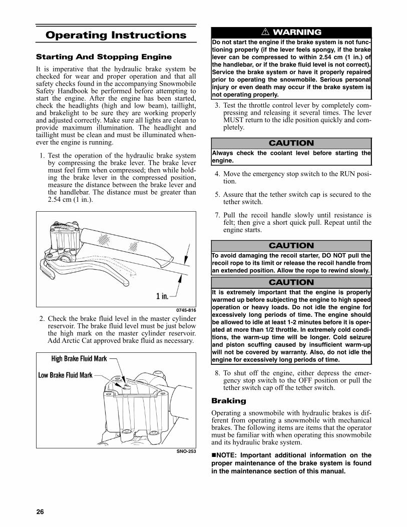
1. Test the operation of the hydraulic brake systemby compressing the brake lever. The brake levermust feel firm when compressed; then while hold-ing the brake lever in the compressed position,measure the distance between the brake lever andthe handlebar. The distance must be greater than2.54 cm (1 in.).
0745-816
2. Check the brake fluid level in the master cylinderreservoir. The brake fluid level must be just belowthe high mark on the master cylinder reservoir.Add Arctic Cat approved brake fluid as necessary.
SNO-253
3. Test the throttle control lever by completely com-pressing and releasing it several times. The leverMUST return to the idle position quickly and com-pletely.
4. Move the emergency stop switch to the RUN posi-tion.
5. Assure that the tether switch cap is secured to thetether switch.
7. Pull the recoil handle slowly until resistance isfelt; then give a short quick pull. Repeat until theengine starts.
8. To shut off the engine, either depress the emer-gency stop switch to the OFF position or pull thetether switch cap off the tether switch.
Braking
Operating a snowmobile with hydraulic brakes is dif-ferent from operating a snowmobile with mechanicalbrakes. The following items are items that the operatormust be familiar with when operating this snowmobileand its hydraulic brake system.
NOTE: Important additional information on theproper maintenance of the brake system is foundin the maintenance section of this manual.
! WARNINGDo not start the engine if the brake system is not func-tioning properly (if the lever feels spongy, if the brakelever can be compressed to within 2.54 cm (1 in.) ofthe handlebar, or if the brake fluid level is not correct).Service the brake system or have it properly repairedprior to operating the snowmobile. Serious personalinjury or even death may occur if the brake system isnot operating properly.
CAUTIONAlways check the coolant level before starting theengine.
CAUTIONTo avoid damaging the recoil starter, DO NOT pull therecoil rope to its limit or release the recoil handle froman extended position. Allow the rope to rewind slowly.
CAUTIONIt is extremely important that the engine is properlywarmed up before subjecting the engine to high speedoperation or heavy loads. Do not idle the engine forexcessively long periods of time. The engine shouldbe allowed to idle at least 1-2 minutes before it is oper-ated at more than 1/2 throttle. In extremely cold condi-tions, the warm-up time will be longer. Cold seizureand piston scuffing caused by insufficient warm-upwill not be covered by warranty. Also, do not idle theengine for excessively long periods of time.
26

1. Use the brakes wisely. Each time the brakes areapplied in all hydraulic brake systems (includingautomotive applications), heat is transferred to thebrake fluid. The amount of heat transferred duringhigh speed stops and/or repetitive use may be highenough to boil the brake fluid and cause the brakesto either fade or may cause an unexpected loss ofbrakes. If this occurs, the brake fluid requires a cooldown period before the brakes will again functionproperly. This cool down period will vary dependingupon the ambient air temperature and the tempera-ture of the brake fluid. If loss of brakes has occurredbecause of high fluid temperatures, do not operatethe snowmobile until the cool down period hasexpired and brake lever firmness has returned.
2. Be sure to maintain the brake fluid at the properlevel and take care not to get any moisture in the sys-tem as moisture in the brake fluid lowers the boilingpoint. If the brake fluid is ever boiled (by high speedstops or repetitive use) or if moisture is allowed toenter the system, it must be changed. Never substi-tute or mix different types or grades of brake fluid.
3. Never ride the brake. Even maintaining minimalpressure on the brake lever will cause the brakepads to drag on the disc and may overheat thebrake fluid.
4. The brake lever lock is not a parking brake andshould not be applied for periods exceeding 5 min-utes. NEVER OPERATE THE SNOWMOBILEWITH THE BRAKE LEVER LOCK ENGAGED.
5. Pumping the brake lever is permissible but not accept-able on a snowmobile designed for racing; therefore,if pumping the brake lever more than twice is neces-sary to obtain the necessary stopping power, the sys-tem must be serviced. If the operator does not feelqualified to service the brake system, see an autho-rized Arctic Cat Snowmobile dealer for this service.
6. When new brake pads are installed, a “burnishing”process is required. Drive the snowmobile slowlyand compress the brake lever several times untilthe pads just start to heat up; then allow them tothoroughly cool down. This process stabilizes thepad material and extends the life of the pads.
Emergency Stopping
There are several methods of stopping or slowing thesnowmobile under a variety of situations. Identified inthe following chart are the ways a snowmobile may bebrought to a stop and the effectiveness under normalconditions.
! WARNINGExcessive repetitive use of the hydraulic brake forhigh speed stops will cause overheating of the brakefluid and premature brake pad wear which will resultin an unexpected loss of brakes.
! WARNINGUse only Arctic Cat approved brake fluid. Never sub-stitute or mix different types or grades of brake fluid.Brake loss can result. Check brake fluid level and padwear before each use. Brake loss can result in severeinjury or even death.
! WARNINGThe brake lever lock is not a parking brake and shouldnot be applied for periods exceeding 5 minutes. Thebrake lever lock maintains the brake lever in the com-pressed position and maintains pressure against thebrake disc; however, after a period of time, the pres-sure applied to the brake disc may relax below theamount required to hold the snowmobile stationary.
ITEM FUNCTION CONDITIONEmergency Stop Switch interrupts ignition circuit ALL
Tether Switch interrupts ignition circuit ALL
Brake slows the driveshaft ALL
! WARNINGIf any malfunction of the throttle system occurs (suchas freezing in fluffy snow) and the engine does not idledown, use the emergency stop switch or disconnectthe tether switch IMMEDIATELY to stop the engine. DONOT start the engine until the malfunction in the throt-tle system has been located and corrected.
! WARNINGIf the throttle control lever does not work properly, DONOT ATTEMPT TO START THE ENGINE.
27

Lubrication
Chain Case
The recommended amount of synthetic chain lube inthe chain case is 15 fl oz. Adding more transmissionlube to the chain case (above the recommendedamount) may result in leakage. To check the transmis-sion lube level, use the following procedure:
NOTE: The snowmobile must be on a level surfacefor this procedure.
Check chain case lube level using the chain case sightglass at the right-side footrest. If the lube is at leasthalfway up the sight glass, the level is correct.
0746-115
3. If the lubricant level is above the add mark, thelubricant level is satisfactory. If the lubricant levelis below the add mark, proceed to step 4.
4. If oil is low, add transmission lube by removing theoil fill plug.
0746-471
NOTE: If excessive oil deposits are observed, thechain case must be serviced. Also, when the oil levelis at the add mark, approximately 2 fl oz of transmis-sion lube must be added to the chain case.
Rear Suspension
1. With the gas tank nearly empty (less than 1/4 full),lay the snowmobile on its side. A piece of card-board should be used to protect the finish on thehood and belly pan.
NOTE: Prior to tipping the snowmobile on itsside, apply the brake and set the brake lever lock.
2. Lubricate the grease fittings with an all-tempera-ture grease.
0746-474
0746-475
CAUTIONThe correct lubricant to use in the chain case is ArcticCat Synthetic Chain Lube (p/n 5639-038). Any substi-tute may cause premature chain failure or seriousdamage to the chain drive system.
28
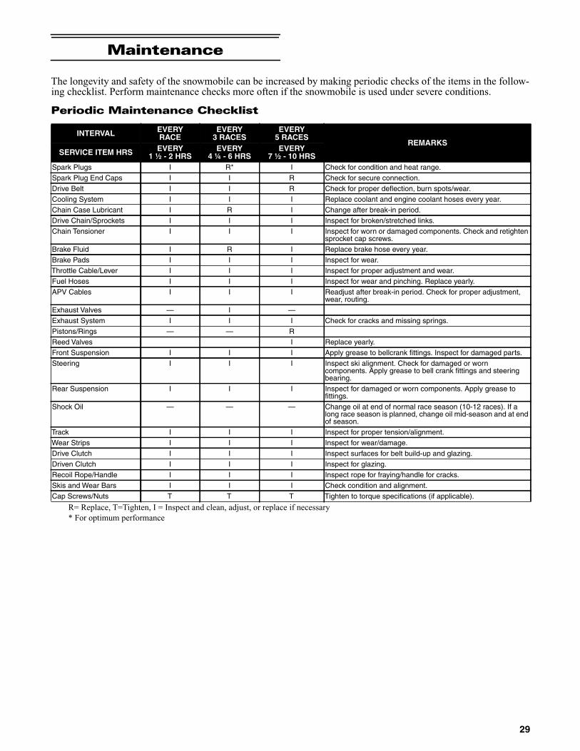
Maintenance
The longevity and safety of the snowmobile can be increased by making periodic checks of the items in the follow-ing checklist. Perform maintenance checks more often if the snowmobile is used under severe conditions.
Periodic Maintenance Checklist
R= Replace, T=Tighten, I = Inspect and clean, adjust, or replace if necessary
* For optimum performance
INTERVAL EVERYRACE
EVERY3 RACES
EVERY5 RACES
REMARKSSERVICE ITEM HRS EVERY
1 ½ - 2 HRSEVERY
4 ¼ - 6 HRSEVERY
7 ½ - 10 HRSSpark Plugs I R* I Check for condition and heat range.
Spark Plug End Caps I I R Check for secure connection.
Drive Belt I I R Check for proper deflection, burn spots/wear.
Cooling System I I I Replace coolant and engine coolant hoses every year.
Chain Case Lubricant I R I Change after break-in period.
Drive Chain/Sprockets I I I Inspect for broken/stretched links.
Chain Tensioner I I I Inspect for worn or damaged components. Check and retightensprocket cap screws.
Brake Fluid I R I Replace brake hose every year.
Brake Pads I I I Inspect for wear.
Throttle Cable/Lever I I I Inspect for proper adjustment and wear.
Fuel Hoses I I I Inspect for wear and pinching. Replace yearly.
APV Cables I I I Readjust after break-in period. Check for proper adjustment,wear, routing.
Exhaust Valves — I —
Exhaust System I I I Check for cracks and missing springs.
Pistons/Rings — — R
Reed Valves I Replace yearly.
Front Suspension I I I Apply grease to bellcrank fittings. Inspect for damaged parts.
Steering I I I Inspect ski alignment. Check for damaged or worncomponents. Apply grease to bell crank fittings and steeringbearing.
Rear Suspension I I I Inspect for damaged or worn components. Apply grease tofittings.
Shock Oil — — — Change oil at end of normal race season (10-12 races). If along race season is planned, change oil mid-season and at endof season.
Track I I I Inspect for proper tension/alignment.
Wear Strips I I I Inspect for wear/damage.
Drive Clutch I I I Inspect surfaces for belt build-up and glazing.
Driven Clutch I I I Inspect for glazing.
Recoil Rope/Handle I I I Inspect rope for fraying/handle for cracks.
Skis and Wear Bars I I I Check condition and alignment.
Cap Screws/Nuts T T T Tighten to torque specifications (if applicable).
29

Pre-Race/Practice Checklist
If, at any time, abnormal noises, vibrations, orimproper working conditions of any component of thissnowmobile are detected, DO NOT OPERATE THESNOWMOBILE. Immediately diagnose and repairany component. If the operator does not feel qualifiedto service the suspension, see an authorized Arctic CatSnowmobile dealer for this service.
Engine
This engine sub-section has been organized to show aprogression for the removing/installing of the Arctic Cat6000 engine. For consistency purposes, this sub-sectionshows a complete and thorough progression; however,for efficiency it may be preferable to remove only thosecomponents needing to be addressed. Also, some compo-nents may vary from model to model. The technicianshould use discretion and sound judgment.
SPECIAL TOOLS
A number of special tools must be available to the technicianwhen performing service procedures in this engine section.
NOTE: Special tools are available from the ArcticCat Service Parts Department.
Removing
NOTE: For assembling purposes, note cable tie loca-tions securing the harness and cables to the chassis.
NOTE: Prior to removing the engine, disconnect thehood harness and remove the side access panels; thenremove the screws securing the hood to the chassis.
0746-793A
1. Carefully remove the exhaust temperature sensorfrom the expansion chamber.
2. Remove all springs securing the expansion chamberand resonator; then remove the expansion chamberand resonator.
3. Remove the torx screw from the driven clutch andslide the driven clutch (along with the drive belt) offthe driven shaft. Account for alignment washers.
PRE-RACE/PRACTICE CHECKLISTWHAT TOCHECK CHECK FOR
Spark Plugs 1. Tightness and loose end caps2. High tension wires
Coolant 1. Proper levelChain Case Oil 1. Proper levelDrive Chain 1. Adjusted to proper tensionDrive Clutch/Driven Clutch
1. Clean sheaves2. Smooth operation
Drive Belt 1. Wear2. Delamination3. Within specifications4. Proper deflection
Brake 1. Brake lever condition and movement2. Fluid level3. Operation of system
Brake Pads 1. WearThrottle 1. Proper cable routing and adjustment
2. Smooth operationAPV System 1. Proper cable routing and adjustment
2. Proper operationExhaust 1. Properly secured
2. Missing springsSteering 1. Smoothness
2. Proper ski alignmentTrack 1. Tension
2. AlignmentSuspension 1. Smooth operation
2. Loose or damaged components3. Spring pre-load adjustment
ShockAbsorbers
1. Leakage2. Component damage3. Proper calibration/air pressure4. Properly routed and secured hose
Gas Tank 1. Secured properly2. Leakage3. Proper fuel level
Fuel Lines 1. Contact wear2. Pinching
Cap ScrewsNuts
1. Tighten to torque specifications(if applicable)
Lights andTether
1. Proper operation (including brakelight)
Snowflap 1. RestraintsSkid Plate 1. Lower belly pan for holes or tears
Description p/nDrive Clutch Bolt Tool 0644-281
Drive Clutch Puller 0744-062
Drive Clutch Spanner Wrench 0644-136
Hood Harness Extension 1686-659
CAUTIONNever attempt to substitute any other drive clutch pullerfor the recommended puller or severe clutch or crank-shaft damage will occur.
30

4. Using Drive Clutch Bolt Tool, remove the torx-headscrew and high-collar washer securing the driveclutch to the crankshaft.
5. Using Drive Clutch Puller and Drive Clutch SpannerWrench, tighten the puller. Remove the drive clutch.
NOTE: If the drive clutch will not release, sharplystrike the head of the puller. Repeat this step until theclutch releases.
6. Remove the two screws (A) securing the heat shieldto the chassis; then remove the heat shield from thetwo front locating pins (B) and remove the heatshield.
EL-001A
7. Disconnect the ECM; then remove the screws secur-ing the right- and left-side fascia panels to the chas-sis. Remove the panels and ECM as an assembly.
EL-002A
8. Remove the cap screws securing the PTO-side frontspar to the steering support and shock mount bracket;then remove the spar.
NOTE: Take care to not drop the spar inserts andnuts when removing the spar.
9. Using a small needle-nose pliers, remove the servo-motor cable holder; then pull the cable housingsdown and out of the servomotor.
EL-004A
10. Slide each cable end out of the slot of the clutch; thendisconnect the harness from the servomotor.
11. Remove the cap screws and lock nuts securing theshock mount bracket support to the shock mountbrackets; then remove the shock mount bracket sup-port.
EL-003A
12. Remove idle speed control (ISC) hoses (A) from thetop of the throttle bodies; then disconnect the ISCfrom the main harness (B). Remove the screws (C)securing the ISC; then remove the ISC.
EL-006A
13. Loosen the four clamps securing the throttle body;then lift up the throttle body and disconnect the cool-ant hoses. Set the throttle body up and out of the way.
14. Remove the intake boot from the chassis.
15. Remove all three oil hoses from the front of theengine.
31

16. Loosen the clamp securing the gasline hose to thethrottle body and remove the hose; then close-off thehose and secure the hose up and out of the way.
17. Remove the main harness wrap and disconnect thesix harness connectors. Secure the harness up andout of the way.
18. Remove the recoil starter from the engine. Secure itout of the way.
19. Remove the cap screws securing the MAG-sideengine mount to the engine.
20. Remove the spark plug caps from the spark plugs;then disconnect the knock sensor and coolant tem-perature sensor connectors. Remove the cylinderhead vent hose.
CWI-092
21. Disconnect the lower coolant hose from the frontheat exchanger; then remove the coolant hose fromthe heat exchanger at the rear of the engine.
PC141A
PC178A
22. Remove the four screws securing the PTO-sideengine mounting plate to the engine.
NOTE: Before removing the cap screws, apply asufficient amount of heat to the cap screws to softenthe Loctite.
23. Remove the cap screw and two lock nuts securingthe engine support plate to the chassis; then lift theengine out of the engine compartment.
NOTE: If replacing the engine, make sure to removethe engine support plate, exhaust manifold, and threecoolant hoses for installation on the new engine.
This engine sub-section has been organized to show aprogression for servicing of the Arctic Cat 6000 engine.For consistency purposes, this sub-section shows a com-plete and thorough progression; however, for efficiency itmay be preferable to disassemble only those componentsneeding to be addressed. Also, some components mayvary from model to model. The technician should usediscretion and sound judgment.
SPECIAL TOOLS
A number of special tools must be available to the technicianwhen performing service procedures in this engine section.
NOTE: Special tools are available from the ArcticCat Service Parts Department.
Disassembling
NOTE: When disassembling top-side components,mark MAG-side and PTO-side components for assem-bling purposes.
! WARNINGThe hose may be under pressure; remove it slowly torelease the pressure. Place an absorbent towel aroundthe connection to absorb gas.
Description p/nBall Hone 0644-294
Flywheel Spanner Wrench 0144-007
Flywheel Puller 0744-040
Flywheel Puller Insert 0644-568
Extractor Nut (Medium) 0643-074
Oil Seal Protector Tool 0644-219
Piston Pin Puller 0644-328
Surface Plate 0644-016
Water Pump Bearing and Seal Tool Kit 0644-557
V Blocks 0644-535
Vacuum Test Pump 0644-131
32

1. Using the Flywheel Spanner Wrench to secure theflywheel, remove the flywheel cap screw andwasher; then remove the cap screws securing therecoil cup.
CWI-070
2. Install the Flywheel Puller Insert onto the end of thecrankshaft.
CWI-072
3. Using Flywheel Puller or suitable substitute, removethe flywheel from the crankshaft by tightening thepuller bolt using an pneumatic gun. Account for thekey.
NOTE: To ensure the cleanliness of the flywheelmagnets, place the flywheel (with the magnets facingupward) on a clean bench.
4. Remove the cap screw securing the ground wire tothe crankcase.
5. Remove the screw (A) securing the stator lead wireplate to the crankcase; then remove the screws (B)securing the timing sensors and bracket, remove thesensors, and account for the harness grommets.
CWI-074A
6. Remove the screws securing the stator to the statorplate. Route the stator lead wire out of the crankcase;then remove the stator assembly.
7. Remove the screws securing the stator plate to theengine; then remove the plate.
CWI-005A
NOTE: For assembling purposes, note the indenta-tion (A) of the stator plate is aligned with the harnessopening (B) in the crankcase.
CWI-005B
NOTE: The stator plate screws have Loctite appliedto the threads during assembly. Using an impactdriver, apply a sharp blow to the head of each screwto break the Loctite loose before removal.
8. Remove the cap screws securing the APV assembliesto the cylinders; then remove the APV assembliesand set them aside. Account for all four dowel pinsand make sure the pins do not fall into the engine.
CAUTIONTo prevent damage to the crankshaft, do not threadpuller bolts more than 1/2 in. into the flywheel. Damageto the stator may result.
33

CWI-006A
9. Disconnect the coolant hose from the back of the cyl-inder head.
10. Remove the cap screws with O-rings securing thecylinder head (in the order shown); then separate thehead from the cylinders. Account for the O-rings ontop of the cylinders.
CWI-009
CWI-010
11. Remove the four nuts securing the fuel rail to theback of the cylinders; then remove the fuel rail andinjectors as an assembly. Account for all gaskets.
CWI-011A
12. Remove the eight nuts securing the cylinders to thecrankcase; then using a soft hammer, gently tap thecylinders and remove from the crankcase by liftingthem straight up off their studs. Account for a gasketand alignment pins.
CWI-012
13. Remove the PTO-side piston-pin circlip from thePTO-side piston; then remove the MAG-side piston-pin circlip from the MAG-side piston.
CWI-013A
14. Using Piston Pin Puller and medium Extractor Nut,remove the piston pins from both pistons.
NOTE: For proper assembly, keep all MAG-sidecomponents and all PTO-side components sepa-rated. Assemble them on their proper sides.
CAUTIONWhen removing a cylinder, be sure to support the pistonto prevent damage to the crankcase and piston.
34

CWI-014
15. Lift the pistons clear of the connecting rods andremove the small-end connecting-rod bearings; thenremove the piston rings. Keep each piston with itsrings; keep each piston pin and bearing together as aset.
CWI-015
16. Remove the screws securing the intake flanges.Remove the intake manifolds and reed valve assem-blies.
CWI-020
CWI-081
17. Remove the four screws securing the thermostat cap;then remove the cap, gasket, and thermostat.
CWI-017
NOTE: For assembling purposes, note that thebypass/check valve is directed up.
CWI-018A
18. Remove the seven screws securing the water pumpcover to the crankcase and remove the cover.Account for the O-ring gasket and the alignmentpins.
CAUTIONDO NOT use any type of punch to drive the piston pinfree of the piston; damage may result. Use a piston-pinpuller only.
35

CWI-016A
19. Remove the cap screw securing the impeller. Accountfor the rubber washer and gasket behind the cap screw.Remove the impeller from the shaft.
CWI-082
20. Prior to turning the engine upside down, remove thetwo crankcase torx screws (A) from the water pumpside of the engine; then remove the two cap screws(B) from the magneto housing.
CWI-075A
CWI-023A
21. Tip the crankcase assembly up onto the water pumpside; then remove the black torx-screw from the bot-tom of the crankcase and tip down and drain theinjection oil from the center cavity into a container.
CWI-023A
22. With the bottom side up on two support blocks,remove the cap screws securing the crankcasehalves.
NOTE: Remove the cap screws in order from #10 to#1. The numbers are embossed next to each capscrew.
CWI-024
23. With all screws removed, carefully separate thecrankcase halves in locations shown below only.
36

CWI-076
24. Lift the bottom half of the crankcase off the top half.
25. Lift the crankshaft free from the top half of thecrankcase and slide the crankshaft bearings and oilseals off the crankshaft. Account for the C-ring (A).Remove the bearing retaining pins (B) and accountfor the crankcase dowel pins (C).
CWI-027A
26. Remove the water pump driveshaft from the lowercrankcase half. Account for the thrust washer on theouter end of the shaft.
NOTE: When replacing the inner water pump seals,use the recommended Water Pump Bearing and SealTool Kit only.
27. Place the lower crankcase on the bench with thewater pump side down. Using the long seal driver,drive the mechanical water pump seal from thecrankcase.
FC036
28. Using a pair of snap ring pliers, remove the snap ringsecuring the inner seal in the crankcase.
29. Using the hooked end of the tool, pull the inner sealfree of the crankcase.
30. Using the hooked end of the tool, pry the seal ringfrom the backside of the water pump impeller.
AN327D
Cleaning and Inspecting
CYLINDER HEAD
1. Using a non-metallic carbon removal tool, removeany carbon buildup from the combustion chambersbeing careful not to nick, scrape, or damage the com-bustion chambers or the sealing surfaces.
2. Inspect the spark-plug holes for any damagedthreads.
NOTE: If warpage is suspected, have a qualifiedmachine shop inspect and repair if necessary.
3. Place the cylinder head on a Surface Plate covered with#400 grit wet-or-dry sandpaper. Using light pressure,move each cylinder head in a figure eight motion.Inspect the sealing surface for any indication of highspots. A high spot can be noted by a bright metallic fin-ish. Correct any high spots before assembly by continu-ing to move the cylinder head in a figure eight motionuntil a uniform bright metallic finish is attained.
CAUTIONDO NOT drive any tool between halves (sealing surface)to separate the crankcase. Damage to the sealing sur-faces will result.
CAUTIONCare must be taken to not allow the connecting rods todrop onto the sealing surface of the bottom case half.
CAUTIONWater or parts-cleaning solvent must be used in con-junction with the wet-or-dry sandpaper or damage tothe sealing surface may result.
37

CYLINDERS
1. Using a non-metallic carbon removal tool, removecarbon buildup from the exhaust ports.
2. Wash the cylinders in parts-cleaning solvent.
3. Inspect the cylinders for pitting, scoring, scuffing,and corrosion. If marks are found, repair the surfacewith the Ball Hone and honing oil.
NOTE: To produce the proper 45° crosshatch pat-tern, maintain a low drill RPM. If honing oil is notavailable, use a lightweight, petroleum-based oil.Thoroughly clean the cylinders after honing usingdetergent soap and hot water and dry with com-pressed air; then immediately apply oil to the cylinderbores. If a bore is severely damaged or gouged, thecylinder must be replaced or replated.
4. Place the head surface of each cylinder on the sur-face plate covered with #400 grit wet-or-dry sandpa-per. Using light pressure, move each cylinder in afigure eight motion. Inspect the surface for any indi-cation of high spots. A high spot can be noted by abright metallic finish. Correct any high spots beforeassembly by continuing to move the cylinder in a fig-ure eight motion until a uniform bright metallic fin-ish is attained.
PISTON
1. Using a non-metallic carbon removal tool, removethe carbon buildup from the dome of each piston.
CRANKCASE
1. Scrape of any residual silicone from both the top andbottom crankcase halves making sure not to damagethe sealing surface; then wash the crankcase halvesin parts-cleaning solvent.
NOTE: Before washing the crankcase halves, makesure the four bearing dowel pins have been removedand accounted for.
2. Inspect the crankcase halves for scoring, pitting,scuffing, or any imperfections in the casting.
3. Inspect all threaded areas for damaged or strippedthreads.
4. Inspect the bearing areas for cracks or excessivebearing movement. If evidence of excessive bearingmovement is noted, the crankcase must be replaced.
5. Inspect the bearing dowel pins for wear.
6. Inspect the sealing surfaces of the crankcase halvesfor trueness by placing each crankcase half on thesurface plate covered with #400 grit wet-or-dry sand-paper. Using light pressure, move each half in a fig-ure eight motion. Inspect the sealing surfaces for anyindication of high spots. A high spot can be noted bya bright metallic finish. Correct any high spots bycontinuing to move the half in a figure eight motionuntil a uniform bright metallic finish is attained.
NOTE: Care must be taken not to remove an exces-sive amount of aluminum, or the crankcase must bereplaced. If excessive aluminum is removed, toomuch pre-load will be exerted on the crankshaft bear-ings when assembled.
CRANKSHAFT
NOTE: If any servicing of the connecting rods, cen-ter bearings, or water pump drive gear is necessary,Arctic Cat recommends the crankshaft be taken to aqualified crankshaft rebuild shop for that service.
1. Wash the crankshaft with bearings in parts-cleaningsolvent.
2. Inspect the bearings for wear, scoring, scuffing, dam-age, or discoloration. Rotate the bearings. Bearingsmust rotate freely and must not bind or feel rough. Ifany abnormal condition is noted, replace the bearing.
CWI-060
3. Inspect the connecting-rod bearings by rotatingthem. The bearings must rotate freely and must notbind or feel rough. If a connecting-rod bearing mustbe replaced, the connecting rod and crank pin mustalso be replaced.
CAUTIONWater or parts-cleaning solvent must be used in con-junction with the wet-or-dry sandpaper or damage tothe sealing surface may result.
CAUTIONWater or parts-cleaning solvent must be used in con-junction with the wet-or-dry sandpaper or damage tothe sealing surface may result.
38

CWI-058
4. Visually inspect the springs to make sure they are inproper location on the seals.
CWI-083A
5. Inspect the water pump drive gear for any signs ofworn or chipped teeth. If either condition exists,replace the gear.
NOTE: Lubricate bearings thoroughly prior toassembly.
REMOVING/INSTALLING OUTER CRANKSHAFT BEARINGS
NOTE: The end bearings are not pressed onto thecrankshaft. The bearings can be removed simply bysliding them off the crankshaft.
Inspect the crankshaft bearing area for wear. If any wearis noted on either end, replace the crankshaft end.
NOTE: Install the bearings by sliding each bearingonto the crankshaft making sure the retaining pinhole (A) in the outer race of the bearing is properlypositioned and will align with the retaining pin (B) inthe crankcase.
IO019B
REED VALVE ASSEMBLY
1. Carefully pry the reed assemblies from the intakemanifold and inspect the reed valves for cracks orany deterioration; then remove the screws securingthe reeds.
CWI-084
2. To assemble, place the reed retaining plate (with the lipfacing outward) into position and secure with the screwstightened to 8.5 in.-lb.
NOTE: When installing the outer reed valves, besure the clipped edge matches the clipped edge ofthe reed retaining plate.
CWI-110
3. Install the reed valve assemblies into the intake mani-fold by installing the top and bottom sides of the reedsfirst; then press down making sure the reeds areinstalled flush with the intake manifold.
39

CWI-055
CWI-056
Measuring Critical Components
CYLINDER TRUENESS
1. Measure each cylinder in locations from front to backand side to side top and bottom of the cylinder for atotal of four readings.
CWI-077
2. The trueness (out-of-roundness) is the differencebetween the highest and lowest reading. Maximumtrueness (out-of-roundness) must not exceed 0.004 in.
PISTON SKIRT/CYLINDER CLEARANCE
1. Measure the piston skirt diameter 10 mm from thebottom of the piston (just below the slot). Once themeasurement is final, lock the micrometer.
CWI-080
2. Position a bore gauge between the micrometer pointsand move it from top to bottom and side to side tofind zero; then adjust the gauge to zero.
CWI-090
CWI-089
3. Place the bore gauge in the cylinder and measureeach cylinder in locations from front to back and sideto side top and bottom of the cylinder for a total offour readings. The difference (clearance) must bewithin 0.0031-0.0041 in.
CWI-087
40

CWI-086
PISTON PIN
Measure the piston pin diameter at each end and in thecenter. Acceptable piston pin measurement must bewithin 0.8659-0.8661 in. If any measurement varies bymore than 0.001 in., the piston pin and bearing must bereplaced as a set.
CWI-079
CRANKSHAFT RUNOUT
1. Using the V Blocks, support the crankshaft on thesurface plate.
NOTE: The V blocks should support the crankshafton the middle bearings.
2. Mount a dial indicator and base on the surface plate.Position the indicator contact point against the crank-shaft location points C and D. Zero the indicator androtate the crankshaft slowly. Note the amount ofcrankshaft runout (total indicator reading).
0747-810
3. If runout exceeds 0.002 in. at any of the checkpoints,the crankshaft must be either straightened orreplaced.
Assembling
NOTE: The use of new gaskets and seals is recom-mended when assembling the engine.
NOTE: Prior to assembling the engine, use partscleaning solvent and compressed air and thoroughlyclean the threaded holes of the crankcase and cylin-ders to properly tighten.
NOTE: When the use of a lubricant is indicated, useArctic Cat C-Tec2 engine oil.
1. Apply a thin coat of grease to the inner seal lips ofthe water pump seal.
2. Using the seal driver, position the inner water pumpshaft seal onto the seal driver and gently tap the sealdown into position.
NOTE: Grease must be applied to the lips of theinner seal before installation.
! WARNINGAlways wear safety glasses when drying componentswith compressed air.
41

MS986A
NOTE: The seal must be installed with its springside towards the crankshaft.
3. Install the snap ring securing the inner seal in thecrankcase.
4. Using the seal driver, carefully install the outer waterpump seal. Gently tap the seal down into positionuntil it seats itself against its flange.
5. Secure the upper crankcase half upside-down on asuitable support; then install the C-ring (A), the fourbearing retaining pins (B), and the two crankcasedowel pins (C).
CWI-027A
6. Apply a thin coat of Loctite 5900 Sealant to theentire bottom half of the crankcase sealing surface.
CWI-067
7. Place the crankshaft end bearings into position mak-ing sure the bearing retaining pin holes are posi-tioned inward.
CWI-030A
8. Install the crankshaft into the upper crankcase half.Be sure the alignment hole in each bearing is posi-tioned over its respective retaining pin in the crank-case; then seat the crankshaft.
IO019A
NOTE: To check the bearing for proper position,place the point of a sharp tool into the dimple foundin the bearing race. Strike the tool with the palm ofthe hand in either direction. If the bearing moves, itisn’t positioned correctly and must be rotated until itdrops onto the retaining pin.
9. Assemble the crankcase halves; then install thecrankcase cap screws securing the crankcase halves.
10. Tighten cap screws (1-10) in two steps using the pat-tern shown. First tighten to 15 ft-lb; then tighten to33 ft-lb.
CAUTIONIf the bearings are not properly seated during assembly,the crankcase halves will not seal tightly and severeengine damage will result.
42

742-198A
11. Tighten screw 11 to 20 ft-lb; then turn the engineright-side up and tighten screws 12-15 in two steps to102 in.-lb.
12. Apply a thin coat of grease to the sealing surface ofthe water pump shaft; then place the Oil Seal Protec-tor Tool at the end of the shaft.
13. Rotate the water pump shaft while carefully pushingit through the oil and water pump seals until thedriveshaft and crankshaft gears engage; then removethe oil seal protector tool (A) from the end of theshaft.
IO025A
14. Place the impeller into position and secure with thecap screw (threads coated with blue Loctite #243)and washers. Be sure the rubber side of the washer islubricated with a light coat of grease and directedtoward the impeller. Tighten to 102 in.-lb.
15. Apply a thin film of low-temp grease to the waterpump cover O-ring; then position the O-ring into thewater pump cover. With the alignment pins in place,install the cover. Secure with the screws using acrisscross pattern. Tighten to 102 in.-lb.
CWI-016A
16. Tip the crankcase assembly up on the water pumpside; then pour Arctic Cat C-Tec2 engine oil into thecenter cavity of the crankshaft until the oil is levelwith the shoulder of the shaft (A).
CWI-016A
NOTE: After the center cavity is filled with engineoil, be sure to install the hose with loom onto theupper crankcase half or engine oil will leak from thatarea.
17. Position the shim on the retainer end of the pumpshaft; then install the retainer with a new O-ring.Tighten screws to 102 in.-lb.
18. Secure the reed valve assemblies and intake mani-folds to the engine case using the existing screws.Tighten in two steps to 115 in.-lb in order from theletter A to the letter F (embossed on the manifold).
CAUTIONBe very careful not to damage the seals when installingthe oil pump driveshaft. Twist the driveshaft clockwiseas it enters the seal area and while pushing it throughthe seals.
CAUTIONThe rubber side of the washer securing the impellermust be positioned toward the impeller. If installedincorrectly, a coolant leak will result and engine damagemay occur.
CAUTIONFailure to fill the center cavity of the crankcase assem-bly will result in center gear damage and engine failure.
43

CWI-020
19. With the bypass/check valve of the thermostatdirected to the 12 o’clock position, install the ther-mostat and housing; then in a crisscross pattern,tighten the screws to 102 in.-lb.
CWI-018A
CWI-064
20. Install the dowel pins into the crankcase; then placethe cylinder base gasket into position on the crank-case.
21. Install the piston rings on each piston so the lettersKDN5 on the top (inclined surface) of each ringfaces the dome of the piston.
CWI-078A
22. Apply oil to the connecting-rod small end bearings;then install the small-end bearings.
23. Place each piston over the connecting rod so the indi-cator arrow on each piston will point toward theexhaust ports; then secure with an oiled piston pin.
NOTE: The indicator arrow is found on the pistondome.
24. Install the new circlips so the open end is directedeither up or down.
25. Rotate each piston ring until the ring ends are prop-erly positioned on either side of the ring keeper; thenapply oil to the piston assemblies and cylinder bores.
CWI-063
26. In turn on each cylinder, place a piston holder (orsuitable substitute) beneath the piston skirt andsquare the piston in respect to the crankcase; thenusing a ring compressor or fingers, compress therings and slide the cylinder over the piston. Removethe piston holder and seat the cylinder firmly ontothe crankcase.
NOTE: The cylinders should slide on easily. DO NOTforce the pistons into the cylinders.
CAUTIONIncorrect installation of the piston rings will result inengine damage.
CAUTIONMake sure the circlips are firmly seated before continu-ing with assembly.
44

27. Install each cylinder with the eight existing nuts;then secure the cylinders by tightening the cylinderbase nuts to 15 ft-lb then to 38 ft-lb in a crisscrosspattern.
28. Install the cylinder O-rings (lightly coated with oil)on the top of each cylinder making sure they are cor-rectly positioned in the grooves.
CWI-010
29. Place new O-rings (lightly coated with oil) onto eachof the head cap screws. Place four of these capscrews (from opposite end of each other) into thecylinder head. Thread the spark plugs in part way;then while holding the head above the cylinder, care-fully start and finger-tighten all four cap screwswhile observing the cylinder O-rings to make surethey remain in position. Slowly place the head intoposition on top of the O-rings.
NOTE: To install the remaining cap screws, thespark plugs must be removed.
30. Start and finger-tighten the cap screws being verycareful not to move the cylinder head; then tightenthe cap screws in two steps to 13 ft-lb then 28 ft-lbusing the pattern shown.
0747-890
NOTE: At this point, install the spark plugs; theninstall the knock sensor. Tighten the sensor to 18 ft-lb.
31. Install the coolant inlet hose to the cylinder head andwater pump; then secure using the clamp.
32. Install the fuel rail assembly into the back of the cyl-inders making sure the gaskets are in place; thensecure the rail using new nylon nuts. Tighten to 102in.-lb.
CWI-008
NOTE: At this time if the coolant temperature sen-sor was removed, install the sensor (threads coatedwith blue Loctite #243) and tighten to 18 ft-lb.
NOTE: At this point, pressure test the engine (seethe Engine-Related Items section).
33. With the raised edge of the valve aligned with thechannel of the cylinder, slide the APV assembliesinto position in the cylinders; then secure with capscrews. Tighten to 102 in.-lb.
NOTE: The APV gaskets will align with the contourof the cylinder and APV assemblies when installedcorrectly. Be sure valves move freely after installingby pulling on the valve cable.
CWI-073
CWI-068
34. Secure the stator plate to the crankcase with thescrews (coated with blue Loctite #243) and tightenedto 102 in.-lb.
45

35. Route the stator harness through the opening in thecrankcase; then secure the stator to the stator platewith the screws (coated with blue Loctite #243).Tighten to 10 ft-lb.
36. Secure the upper ignition timing sensor with capscrews (coated with blue Loctite #243). Tighten to80 in.-lb; then install the wiring grommet into thenotch of the crankcase.
37. Secure the lower ignition timing sensor and bracketwith two screws (coated with blue Loctite #243).Tighten to 80 in.-lb; then install the grommet. Withthe stator harness properly positioned, install theplate and cap screw (coated with blue Loctite #243).Tighten to 80 in.-lb.
CWI-074
38. Install the key in the crankshaft (if removed).
NOTE: Before installing the flywheel, be sure towipe the crankshaft and flywheel tapers clean using aclean, lint-free towel.
39. Place the recoil cup in position on the flywheel andvisually center; then secure the cup with three capscrews and tighten only until snug. While holdingthe cup, slide the flywheel onto the crankshaft mak-ing sure the keyways match.
40. Apply red Loctite #271 to the threads of the flywheelcap screw with the large flat washer; then finger-tighten only at this time into the crankshaft.
41. Secure the recoil cup while using the spanner wrenchand tighten the three cap screws (from step 39)evenly to 18 ft-lb.
42. Using the spanner wrench, tighten the flywheel capscrew (from step 40) to 50 ft-lb.
CWI-070
43. Install the exhaust manifold with new gaskets andsecure with the eight nuts. Tighten the nuts in a criss-cross pattern to 12 ft-lb.
44. If the knock sensor was removed, secure it to the cyl-inder head using the existing cap screw. Tighten to18 ft-lb.
45. After installing the engine, bleed the oil lines usingthe Oil Bleeding Procedure included with the CATTII Tool.
Installing
NOTE: If the engine was replaced, make sure toinstall the existing engine support plate and theexhaust manifold on the new engine. Tighten theexhaust manifold nuts to 12 ft-lb, the M6 engine sup-port plate cap screws to 25 ft-lb, and the M8 enginecap screws to 35 ft-lb. Install the three coolant hoses.
NOTE: On electric start models, install the startermotor to the engine.
NOTE: If the engine is brand new, tip the crankcaseassembly up on the water pump side; then pour Arc-tic Cat C-Tec2 engine oil into the center cavity of thecrankshaft until the oil is level with the shoulder ofthe shaft (A).
CWI-085A
CAUTIONFailure to fill the center cavity of the crankcase assem-bly will result in center gear damage and engine failure.
46

1. Carefully lower the engine into the engine compartment.
2. Install the coolant hose to the heat exchanger at therear of the engine; then connect the lower coolanthose to the front heat exchanger.
PC141A
PC178A
3. Install new MAG-side engine mount “patch-lock”cap screws. Finger-tighten only at this time.
4. Install a new “patch-lock” cap screw and new locknuts to secure the engine support plate to the chassis.Finger-tighten only at this time.
5. Install four new “patch-lock” screws to secure thePTO-side engine mounting plate. Tighten to 30 ft-lbusing a crisscross pattern.
6. Tighten the cap screw and lock nuts (from step 4) to25 ft-lb.
7. Install the access panel to the center belly panel andchassis and secure using the torx-head screws. Tightensecurely.
8. Tighten the cap screws (from step 3) to 25 ft-lb.
9. Connect the knock sensor and coolant temperaturesensor connectors; then install the spark plug caps.Secure the coolant temperature sensor connectorwith a cable tie.
10. Install the cylinder head vent hose.
11. Place the recoil starter into position and secure with thecap screws. Tighten in a crisscross pattern to 96 in.-lb.
12. Before connecting the wiring harness plug-ins, cleanthe connectors and apply Dielectric Grease to theseal; then connect all harness connectors makingsure all wiring and coolant hoses are routed properlyas noted in removing. Install the main harness wrap.
NOTE: Use cable ties to secure the wiring har-nesses as necessary.
13. Connect all three oil hoses from the front of theengine. Secure using the existing clamps.
EL-005A
14. Connect the MAG-side throttle body coolant hose;then secure with a clamp.
15. Connect the TPS; then lower the throttle bodyassembly into the engine compartment.
16. Place the throttle body assembly into position andsecure with the flange clamps; then connect thegasline hose to the throttle body assembly andtighten the clamp securely.
17. Connect the PTO-side throttle body coolant hose;then secure with a clamp.
18. Fill the cooling system (see Liquid Cooling Systemin the Engine-Related Items section).
19. Using the existing clamps, secure the intake flangesto the throttle bodies.
20. With the air intake boot properly positioned on thethrottle bodies, secure with the existing clamps.
21. Install the shock mount bracket support; then usingnew lock nuts, secure the support to the shock mountbrackets and tighten to 20 ft-lb.
CAUTIONWhen installing the throttle bodies, make sure thegasline hose is properly routed to avoid premature wearand/or contact with exhaust components.
47
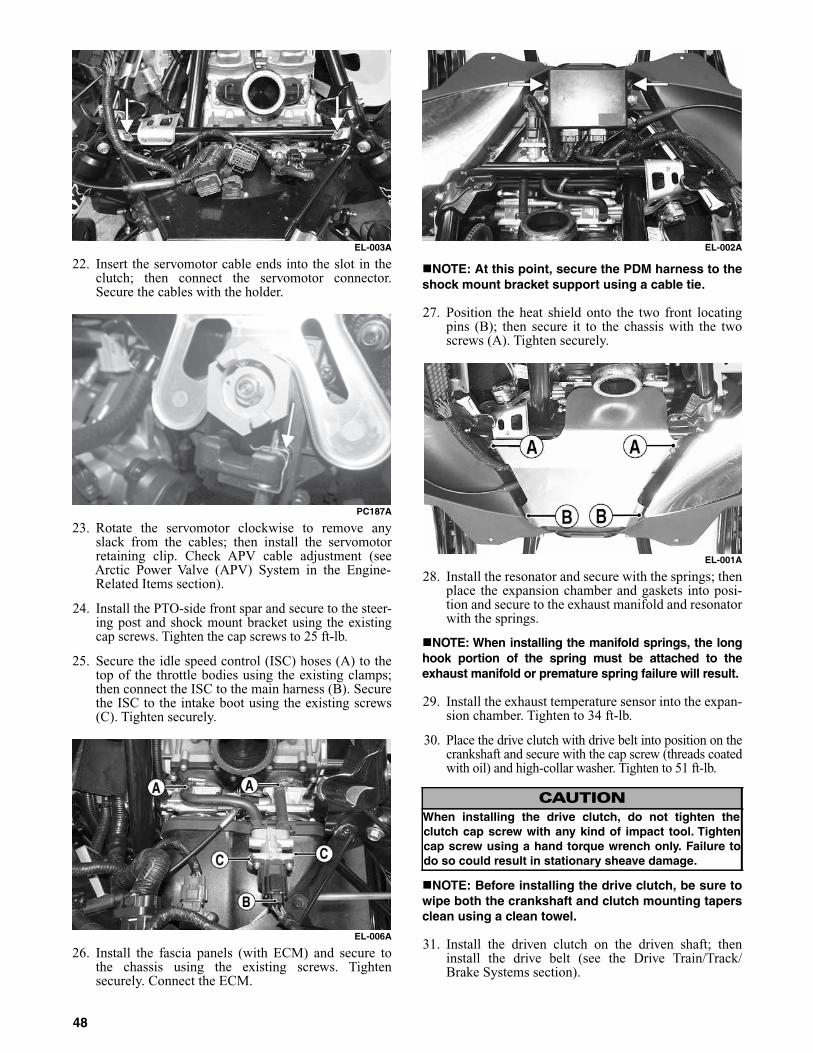
EL-003A
22. Insert the servomotor cable ends into the slot in theclutch; then connect the servomotor connector.Secure the cables with the holder.
PC187A
23. Rotate the servomotor clockwise to remove anyslack from the cables; then install the servomotorretaining clip. Check APV cable adjustment (seeArctic Power Valve (APV) System in the Engine-Related Items section).
24. Install the PTO-side front spar and secure to the steer-ing post and shock mount bracket using the existingcap screws. Tighten the cap screws to 25 ft-lb.
25. Secure the idle speed control (ISC) hoses (A) to thetop of the throttle bodies using the existing clamps;then connect the ISC to the main harness (B). Securethe ISC to the intake boot using the existing screws(C). Tighten securely.
EL-006A
26. Install the fascia panels (with ECM) and secure tothe chassis using the existing screws. Tightensecurely. Connect the ECM.
EL-002A
NOTE: At this point, secure the PDM harness to theshock mount bracket support using a cable tie.
27. Position the heat shield onto the two front locatingpins (B); then secure it to the chassis with the twoscrews (A). Tighten securely.
EL-001A
28. Install the resonator and secure with the springs; thenplace the expansion chamber and gaskets into posi-tion and secure to the exhaust manifold and resonatorwith the springs.
NOTE: When installing the manifold springs, the longhook portion of the spring must be attached to theexhaust manifold or premature spring failure will result.
29. Install the exhaust temperature sensor into the expan-sion chamber. Tighten to 34 ft-lb.
30. Place the drive clutch with drive belt into position on thecrankshaft and secure with the cap screw (threads coatedwith oil) and high-collar washer. Tighten to 51 ft-lb.
NOTE: Before installing the drive clutch, be sure towipe both the crankshaft and clutch mounting tapersclean using a clean towel.
31. Install the driven clutch on the driven shaft; theninstall the drive belt (see the Drive Train/Track/Brake Systems section).
CAUTIONWhen installing the drive clutch, do not tighten theclutch cap screw with any kind of impact tool. Tightencap screw using a hand torque wrench only. Failure todo so could result in stationary sheave damage.
48

32. Check drive belt deflection.
33. Place the hood into position on the front end andsecure with the screws; then install the hood harness.Install the side access panels.
34. Start the engine and warm up to operating tempera-ture; then verify that all components are functioningproperly and that coolant is circulating through thecooling system properly.
35. After running the engine to the proper operating tem-perature, shut the engine off; then open the accesspanels and inspect for any signs of coolant, gasoline,or oil leakage.
36. Allow the engine to cool; then check the coolantlevel and add coolant as necessary. Verify the tight-ening torque of the drive clutch.
Track Drive
Removing
1. Remove the right and left side panels and setaside; then remove the resonator.
2. Place a suitable safety stand beneath the rear bum-per taking the weight of the snowmobile off therear suspension.
3. Remove all torx-head screws and cap screwssecuring the brake disc shield to the chassis.
RA031A
4. Remove the pin and allen-head screws securingthe brake caliper halves together; then remove theretaining ring securing the brake disc. Remove thebrake disc.
RA032A
RA030A
5. Remove the cap screws securing the slide railassembly.
NOTE: At this time, it is recommended to havethe snowmobile tipped on the left-side.
6. Remove all torx-head screws securing the chaincase cover. Remove cover.
7. Remove the chain and sprockets. Remove chainlube oil.
RA013
8. Remove the cap screws securing the inner caliper tothe tunnel; then remove the inner caliper and bearings.
NOTE: It may be necessary to use Puller Tool (p/n0744-067) to remove the caliper/bearing assembly.
CAUTIONNever run the engine with the hood harness discon-nected or damage to the electrical system will result.
CAUTIONIf the engine had a major overhaul or if any major com-ponent was replaced, proper engine break-in proce-dures must be followed (see the General Informationsection) or severe engine damage may result.
49

PC148A
9. Pull the driveshaft out to the left; then drop out oftunnel right side first.
NOTE: At this point, inspect the bearings forwear or roughness. Replace as necessary.
Installing
1. Place the track drive assembly into position; theninstall existing chain and sprockets and secureusing the existing retaining ring (bottom sprocket),cap screw and washer (top sprocket). Tighten topcap screw to 25 ft-lb.
2. Tighten chain tensioner; then install chain lube.
3. Install chain case cover using existing torx-headcap screws. Tighten to 12 ft-lb.
4. Place the slide rail assembly into position andsecure with existing cap screws. Tighten to 34 ft-lb.
5. Secure the left side of the track drive assembly tothe inner brake caliper using the existing capscrews. Tighten to 25 ft-lb.
6. Install the brake disc and secure using the existingretaining ring.
7. Secure the brake caliper halves using the existingtwo allen-head screws. Tighten to 25 ft-lb.
8. Secure the brake disc guard using the existingtorx-head screws and cap screws.
9. Install the resonator, side panels, and hood.
Drive Sprockets
Removing
NOTE: The drive sprockets must be removed fromthe brake side of the track drive.
RA027A
1. For installing purposes, scribe a line on the drive-shaft (A) next to the drive sprocket for proper align-ment; then scribe a line on the driveshaft directly inline with the timing arrows (B) on the drive sprock-ets for proper sprocket timing.
RA026A
2. Using a suitable press positioned against the tension-collar of the drive sprocket (located on the chaincase) and of the driveshaft, press the drive sprocketsoff the driveshaft.
RA025A
Cleaning And Inspecting
1. Thoroughly wash all metallic components in parts-cleaning solvent. Dry using compressed air.
2. Wash all non-metallic components with soap andwater.
CAUTIONAlways press against the tension-collar of the drivesprockets or damage to the components will occur.
50

3. Inspect the driveshaft for damaged splines orstripped threads.
4. Inspect the seals for any breaks or damage.
5. Inspect the track for cuts, gouges, or wear.
6. Inspect the brake disc for wear or cracks.
7. Inspect the track drive sprockets for wear or damage.
Installing
NOTE: The drive sprockets must be installed on thebrake side of the track drive.
RA027B
NOTE: Prior to installing the sprockets onto thedriveshaft, lightly chamfer the inside edge of thesprocket to avoid binding.
MS362
1. Properly align the scribed line on the driveshaft(from removing) with the timing arrow on the drivesprocket; then slide the sprocket onto the driveshaftas far as it will go.
2. Using a suitable press and fixture, press the drive-shaft into the sprocket until it aligns with the linescribed in removing.
3. Slide the remaining sprocket onto the driveshaftmaking sure the timing arrow/lines (from removing)are aligned; then using the press/fixture, press thesprocket to the remaining alignment line.
NOTE: When pressing new sprockets on the drive-shaft, align the sprocket alignment marks or thesprockets won’t be timed correctly.
0747-018
4. Press sprockets to proper location (shown in the fol-lowing illustration). Sprockets are to be pressed andmeasured from dropcase end of shaft.
0747-025
Brake System
Arctic Cat recommends that the brake system (brakelever, reservoir, hose, caliper, pads, and brake disc) bechecked daily for fluid leakage, wear, or damage andfor proper operation. Also, the brake fluid level mustbe checked every time before starting the engine. Thebrake fluid must be maintained at a level just belowthe high mark on the reservoir.
Brake Fluid
Checking/Adding
1. With the brake fluid reservoir in a level position andthe cover removed, check the fluid level. The brakefluid level must be at the high brake fluid mark in thereservoir.CAUTION
Always press against the tension-collar of the drivesprockets or damage to the components will occur.
! WARNINGDO NOT operate the snowmobile when the brake leverlock is engaged or when any component in the brake sys-tem is damaged, worn, or adjusted improperly. If thesnowmobile is operated and the brake system is not func-tioning properly, severe personal injury could result.
51

SNO-253
2. If the brake fluid level is below the low mark,remove the reservoir cover and add Arctic Catapproved brake fluid until the fluid level is justbelow the high mark. Install and secure the reser-voir cover. Do not allow moisture to contaminatethe brake system.
Changing
The brake fluid must be changed on a regular basis andwhenever the brake fluid has been overheated or con-taminated. The brake fluid should be changed every1000 miles or at the end of the snowmobiling season,whichever occurs first.
Checking Brake Lever Travel
1. Test the operation of the hydraulic brake system bycompressing the brake lever.
2. The brake lever must feel firm when compressed.
3. To verify lever travel, compress and hold the brakelever to its maximum resistance.
NOTE: Do not pump the brake lever as it will pro-duce an inaccurate reading.
4. Measure the distance between the brake lever and thehandlebar. The distance must be greater than 1 in.
0745-816
5. If the distance is less than specified, check the brakefluid level (see Checking Brake Fluid in this sub-sec-tion), inspect for leakage, and check the brake pads.
Bleeding Brake System
If the brake lever feels spongy when applied, the brakesystem may need to be bled. To bleed the brake, usethe following procedure:
1. Remove the reservoir cover and fill the reservoir tothe high mark with Arctic Cat approved brake fluid.
2. Slide a piece of flexible tubing over the ball of thebleeder valve and direct the other end into a con-tainer.
RA032B
3. Slowly compress the brake lever and hold. Openthe bleeder valve to release the fluid and air. Whenthe fluid stops, close the bleeder valve; thenrelease the brake lever.
CAUTIONBrake fluid is highly corrosive. Do not spill brake fluidon any surface of the snowmobile.
! WARNINGDo not overfill the reservoir. Overfilling the reservoir maycause the brake system to hydraulically lock. Use onlyArctic Cat approved brake fluid. Never substitute or mixdifferent types or grades of brake fluid. Brake loss canresult. Brake loss can result in severe injury or even death.
! WARNINGDo not operate the snowmobile if the distance betweenthe compressed brake lever and handlebar is less than2.54 cm (1 in.). Brake loss may occur. Brake loss canresult in severe personal injury.
CAUTIONBrake fluid is highly corrosive. Do not spill brake fluidon any surface of the snowmobile.
! WARNINGUse only Arctic Cat approved brake fluid. Any substi-tute may result in a loss of brakes.
52
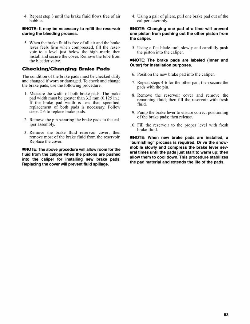
4. Repeat step 3 until the brake fluid flows free of airbubbles.
NOTE: It may be necessary to refill the reservoirduring the bleeding process.
5. When the brake fluid is free of all air and the brakelever feels firm when compressed, fill the reser-voir to a level just below the high mark; theninstall and secure the cover. Remove the tube fromthe bleeder valve.
Checking/Changing Brake Pads
The condition of the brake pads must be checked dailyand changed if worn or damaged. To check and changethe brake pads, use the following procedure.
1. Measure the width of both brake pads. The brakepad width must be greater than 3.2 mm (0.125 in.).If the brake pad width is less than specified,replacement of both pads is necessary. Followsteps 2-6 to replace brake pads.
2. Remove the pin securing the brake pads to the cal-iper assembly.
3. Remove the brake fluid reservoir cover; thenremove most of the brake fluid from the reservoir.Replace the cover.
NOTE: The above procedure will allow room for thefluid from the caliper when the pistons are pushedinto the caliper for installing new brake pads.Replacing the cover will prevent fluid spillage.
4. Using a pair of pliers, pull one brake pad out of thecaliper assembly.
NOTE: Changing one pad at a time will preventone piston from pushing out the other piston fromthe caliper.
5. Using a flat-blade tool, slowly and carefully pushthe piston into the caliper.
NOTE: The brake pads are labeled (Inner andOuter) for installation purposes.
6. Position the new brake pad into the caliper.
7. Repeat steps 4-6 for the other pad; then secure thepads with the pin.
8. Remove the reservoir cover and remove theremaining fluid; then fill the reservoir with freshfluid.
9. Pump the brake lever to ensure correct positioningof the brake pads; then release.
10. Fill the reservoir to the proper level with freshbrake fluid.
NOTE: When new brake pads are installed, a“burnishing” process is required. Drive the snow-mobile slowly and compress the brake lever sev-eral times until the pads just start to warm up; thenallow them to cool down. This procedure stabilizesthe pad material and extends the life of the pads.
53

Drive Train/Track/Brake Systems
This section has been organized into sub-sections for ser-vicing drive train, track, and brake systems; however,some components may vary from model to model. Thetechnician should use discretion and sound judgmentwhen removing and installing components.
NOTE: Whenever a part is worn excessively, cracked,or damaged in any way, replacement is necessary.
SPECIAL TOOLS
A number of special tools must be available to the technicianwhen servicing the drive train, track, and brake systems.
NOTE: Special tools are available from the ArcticCat Service Parts Department.
Drive Belt
The drive belt transfers power from the drive clutch tothe driven clutch. If the belt is worn, cracked, orstretched, maximum power will not be transmitted andthe belt could also fail and therefore must be replaced.Periodic checks (at least once a week under normalusage) of two drive belt specifications are essential.
1. Measure the outside circumference of the drivebelt. The belt should be within specifications incircumference.
2. Measure the outside width of the drive belt. Thebelt should be within specifications in width.
3. Check the belt for cracking, fraying, etc.
If any of the specifications or conditions are unsatis-factory, replace the drive belt.
NOTE: Drive belts should be purchased from an.authorized Arctic Cat Snowmobile dealer, as ArcticCat drive belts are made to exact specificationsand of quality material. Belts made by other manu-facturers may not be of the same specifications orquality and, therefore, usage could result in poorperformance and premature belt failure.
Before starting the snowmobile in extremely cold tem-peratures, the drive belt should be removed andwarmed up to room temperature. Once the drive belt isat room temperature, install the drive belt.
Also, drive belts have a break-in period of approxi-mately 10 minutes. After installing a new drive belt,drive the snowmobile for 10 minutes at 1/2 throttle orless. This will allow the drive belt to gain its optimumflexibility and will extend drive belt life.
Breaking-In
Drive belts require a break-in period of approximately25 miles. Drive the snowmobile for 25 miles at 3/4throttle or less. By revving the engine up and down(but not exceeding 60 mph), the exposed cord on theside of a new belt will be worn down. This will allowthe drive belt to gain its optimum flexibility and willextend drive belt life.
Removing
1. Remove the tether switch cap and wait for allmoving parts to stop.
2. Set the brake lever lock.
3. Remove the left-side access panel.
4. Using Drive Belt Deflection Tool (p/n 0644-424),thread the tool clockwise into the driven clutchuntil the movable sheave opens far enough toremove the drive belt.
743-067B
5. When the sheaves are fully apart, pull up on drivebelt and roll belt over stationary sheave until it isfree of the driven clutch.
Description p/nDrive Clutch Bolt Tool 0644-281
Bearing Removal and Installation Tool 0644-167
Movable Sheave Bearing Tool 0644-594
Clutch Alignment Bar 0644-428
Drive Clutch Puller 0744-062
Drive Clutch Spanner Wrench 0644-136
Driven Clutch Compressor Tool 0644-444
Rear Suspension Spring Tool 0144-311
Brake Caliper Bearing Puller 0744-067
CAUTIONNever attempt to substitute any other drive clutch puller forthe recommended puller or severe clutch damage will occur.
CAUTIONNever run the engine with the drive belt removed.Excessive revving of the engine could result in seri-ous engine damage and drive clutch failure.
54
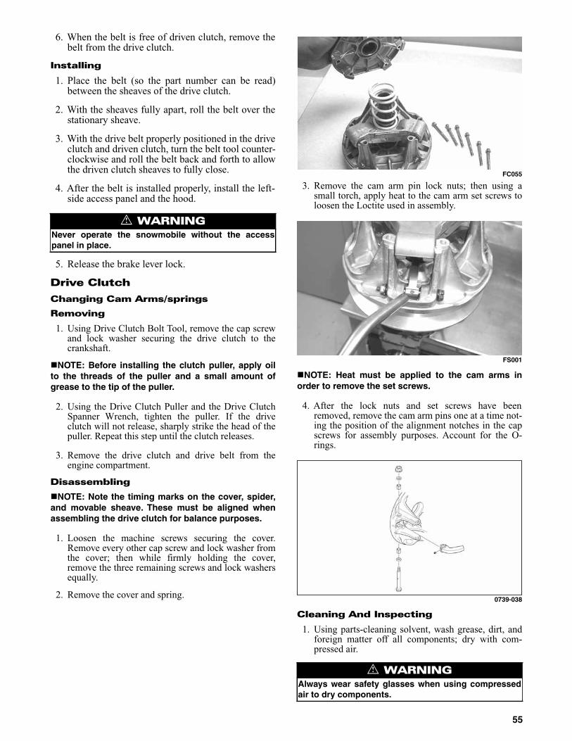
6. When the belt is free of driven clutch, remove thebelt from the drive clutch.
Installing
1. Place the belt (so the part number can be read)between the sheaves of the drive clutch.
2. With the sheaves fully apart, roll the belt over thestationary sheave.
3. With the drive belt properly positioned in the driveclutch and driven clutch, turn the belt tool counter-clockwise and roll the belt back and forth to allowthe driven clutch sheaves to fully close.
4. After the belt is installed properly, install the left-side access panel and the hood.
5. Release the brake lever lock.
Drive Clutch
Changing Cam Arms/springs
Removing
1. Using Drive Clutch Bolt Tool, remove the cap screwand lock washer securing the drive clutch to thecrankshaft.
NOTE: Before installing the clutch puller, apply oilto the threads of the puller and a small amount ofgrease to the tip of the puller.
2. Using the Drive Clutch Puller and the Drive ClutchSpanner Wrench, tighten the puller. If the driveclutch will not release, sharply strike the head of thepuller. Repeat this step until the clutch releases.
3. Remove the drive clutch and drive belt from theengine compartment.
Disassembling
NOTE: Note the timing marks on the cover, spider,and movable sheave. These must be aligned whenassembling the drive clutch for balance purposes.
1. Loosen the machine screws securing the cover.Remove every other cap screw and lock washer fromthe cover; then while firmly holding the cover,remove the three remaining screws and lock washersequally.
2. Remove the cover and spring.
FC055
3. Remove the cam arm pin lock nuts; then using asmall torch, apply heat to the cam arm set screws toloosen the Loctite used in assembly.
FS001
NOTE: Heat must be applied to the cam arms inorder to remove the set screws.
4. After the lock nuts and set screws have beenremoved, remove the cam arm pins one at a time not-ing the position of the alignment notches in the capscrews for assembly purposes. Account for the O-rings.
0739-038
Cleaning And Inspecting
1. Using parts-cleaning solvent, wash grease, dirt, andforeign matter off all components; dry with com-pressed air.
! WARNINGNever operate the snowmobile without the accesspanel in place.
! WARNINGAlways wear safety glasses when using compressedair to dry components.
55
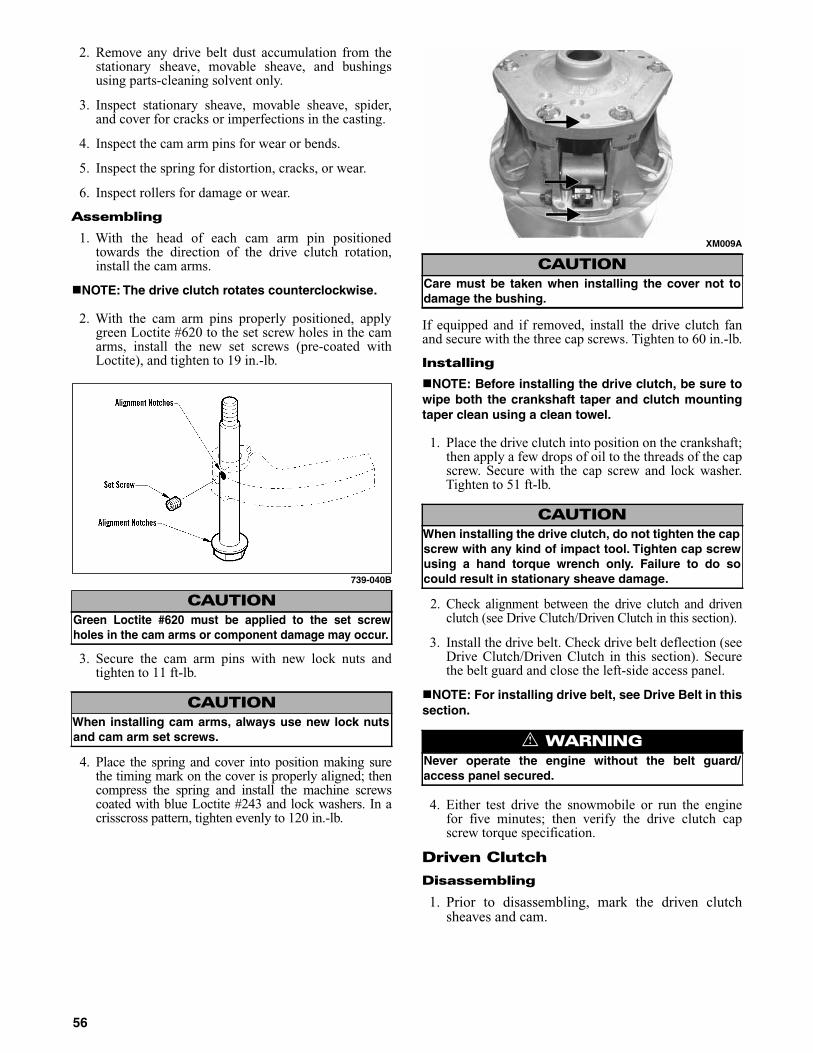
2. Remove any drive belt dust accumulation from thestationary sheave, movable sheave, and bushingsusing parts-cleaning solvent only.
3. Inspect stationary sheave, movable sheave, spider,and cover for cracks or imperfections in the casting.
4. Inspect the cam arm pins for wear or bends.
5. Inspect the spring for distortion, cracks, or wear.
6. Inspect rollers for damage or wear.
Assembling
1. With the head of each cam arm pin positionedtowards the direction of the drive clutch rotation,install the cam arms.
NOTE: The drive clutch rotates counterclockwise.
2. With the cam arm pins properly positioned, applygreen Loctite #620 to the set screw holes in the camarms, install the new set screws (pre-coated withLoctite), and tighten to 19 in.-lb.
739-040B
3. Secure the cam arm pins with new lock nuts andtighten to 11 ft-lb.
4. Place the spring and cover into position making surethe timing mark on the cover is properly aligned; thencompress the spring and install the machine screwscoated with blue Loctite #243 and lock washers. In acrisscross pattern, tighten evenly to 120 in.-lb.
XM009A
If equipped and if removed, install the drive clutch fanand secure with the three cap screws. Tighten to 60 in.-lb.
Installing
NOTE: Before installing the drive clutch, be sure towipe both the crankshaft taper and clutch mountingtaper clean using a clean towel.
1. Place the drive clutch into position on the crankshaft;then apply a few drops of oil to the threads of the capscrew. Secure with the cap screw and lock washer.Tighten to 51 ft-lb.
2. Check alignment between the drive clutch and drivenclutch (see Drive Clutch/Driven Clutch in this section).
3. Install the drive belt. Check drive belt deflection (seeDrive Clutch/Driven Clutch in this section). Securethe belt guard and close the left-side access panel.
NOTE: For installing drive belt, see Drive Belt in thissection.
4. Either test drive the snowmobile or run the enginefor five minutes; then verify the drive clutch capscrew torque specification.
Driven Clutch
Disassembling
1. Prior to disassembling, mark the driven clutchsheaves and cam.
CAUTIONGreen Loctite #620 must be applied to the set screwholes in the cam arms or component damage may occur.
CAUTIONWhen installing cam arms, always use new lock nutsand cam arm set screws.
CAUTIONCare must be taken when installing the cover not todamage the bushing.
CAUTIONWhen installing the drive clutch, do not tighten the capscrew with any kind of impact tool. Tighten cap screwusing a hand torque wrench only. Failure to do socould result in stationary sheave damage.
! WARNINGNever operate the engine without the belt guard/access panel secured.
56

RA020
2. Remove the four torx-head screws securing thecam to the movable sheave; then grasp the camand by working the movable sheave back andforth, lift it up and off the shaft.
RA021
NOTE: If only changing cam angles, move thecam 90° to its optional position and secure thecam with the four torx head cap screws. Tighten to6 ft-lb.
2. Using Driven Clutch Compression Tool (p/n 0644-444), position the tool over the roller assembly;then compress the assembly enough to allow thesnap ring to be removed from the end of the shaft.Remove the snap ring.
RA022A
3. Remove the compression tool and account for thesnap ring, spider assembly, spring, and a retainingring.
4. Remove the movable sheave from the drivenclutch shaft and account for one spacer.
Cleaning And Inspecting
NOTE: Whenever a part is worn excessively,cracked, or damaged in any way, replacement isnecessary.
1. Using a parts-cleaning solvent, wash grease, dirt,and foreign matter off all components; dry withcompressed air.
2. Remove any drive belt dust accumulation from thestationary sheave, movable sheave, and bushingsusing parts-cleaning solvent only.
3. Inspect the roller assembly for wear or damage.
NOTE: Flat spots or diameter cannot be less than23 mm (0.925 in.).
4. Inspect shaft for nicks or burrs.
NOTE: If a spring rate measures less than 10% ofspecified load height, it must be replaced.
5. Measure the inside diameter of the movablesheave bushing. Bushing to shaft clearance mustnot exceed 0.25 mm (0.010 in.).
NOTE: If clearance exceeds the limit, the bushingmust be replaced.
Assembling
1. Install the spacer and the movable sheave onto thedriven clutch shaft.
2. Place the retaining ring and spring into the drivenclutch; then place the roller assembly and snapring over the spring.
3. Position the roller assembly so the “X” mark isdirectly in line with the “X” on the movablesheave.
RA023A
CAUTIONDo not use steel wool or a wire brush to clean com-ponents having a bushing; damage to the bushingwill result.
57

4. With Driven Clutch Compressor (p/n 0644-444),compress the roller assembly enough to allow thesnap ring to be properly secured to the shaft.
CM090
NOTE: While compressing the roller assembly, itmay be necessary to work the spider assemblyback and forth to properly mate the splines.
5. Place the cam with the desired angle into position;then secure the cam to the movable sheave withthe four torx head cap screws. Tighten to 6 ft-lb.
Installing
1. Slide the alignment washers onto the end of thedriven shaft.
2. Place the stub shaft into the driven clutch. Placethe driven clutch on the shaft.
NOTE: A small amount of Loctite Anti-SeizeThread Compound (p/n 0678-146) applied to thedriven shaft will aid in future driven clutchremoval.
3. Secure the driven clutch by installing washers, andcap screw. Tighten the cap screw to 2.6-3.3 kg-m(19-24 ft-lb).
NOTE: Make sure the keyways match wheninstalling the driven clutch. Arrange washers toallow the least amount of “float” on the drivenshaft. A maximum of 1-2 mm (0.040-0.080 in.) offloat is acceptable.
Drive Train
REMOVING CHAIN CASE/DRIVEN SHAFT/DRIVESHAFT/TRACK
1. Remove the left- and right-side panels, hood; thenloosen the quarter turns securing the lower console tothe skid panels and secure out of the way.
2. Remove the drive and driven clutches.
3. Remove the screws securing the PTO engine mountplate to the engine and the chassis.
4. Remove the resonator; then remove the right-sidefootrest.
5. Remove the torx-head screw securing the belly panto the right-side footrest support.
6. Disconnect the speed sensor connector and the oillevel connector.
7. Place a drain pan under the chain case; then loosenthe eleven screws securing the chain case cover/oiltank assembly to the chain case housing starting withthe bottom screws first.
8. Remove the chain case cover/oil tank and set out ofthe way leaving the oil hose(s) connected.
9. Release tension on the chain tensioner; then removethe ratchet block and the tensioner.
XM259
10. Remove the snap ring securing the upper sprocket tothe driven shaft.
XM262
NOTE: Spread the snap rings only enough toremove them from the drive and drive shafts.
11. Remove the snap ring securing the lower sprocket.Remove the sprockets and chain.
58

XM261
XM263
12. Remove the inner black snap ring; then remove thesnap ring and washer securing the driven shaft.
XM264
XM265
13. Once the snap ring and washers have been removedfrom the driven shaft, the shaft and PTO enginemount plate may be removed from the chassis. Makesure to keep the shaft 90° to the plate.
14. Remove the skid frame assembly.
15. Remove the brake shield and the left-side footrest.
NOTE: DO NOT split the brake caliper unless neces-sary service work is required.
16. Remove the cap screws securing the inner caliper tothe tunnel; then remove the caliper and the driveshaftassembly.
PC148A
NOTE: If the caliper will not slide off the driveshafteasily, proceed to step 17.
17. Remove the retaining pin and the brake disc pads;then pump the brake lever 3 or 4 times then pull backand secure the lever to the handlebar using a cabletie. This will keep the fluid from leaking.
NOTE: Place an absorbent towel under the caliperto absorb slight amount of brake fluid. Do not com-press the brake lever.
18. Remove the retaining ring securing the brake disc tothe driveshaft and remove the brake disc.
NOTE: It may be necessary to use Brake CaliperBearing Puller to remove the caliper/bearing assem-bly.
NOTE: If the chain case needs to be removed,remove all machine screws with lock nuts.
CLEANING AND INSPECTING CHAIN CASE
1. Inspect sprockets and chain for excessive wear orstretching.
2. Inspect bearings and sprockets for roughness or chip-ping.
NOTE: If bearing replacement is necessary, thechain case must be removed from the tunnel and anappropriate press utilized to remove and install bear-ings.
59

3. Clean all interior chain case surfaces and compo-nents in cleaning solvent and dry using compressedair.
ASSEMBLING/INSTALLING CHAIN CASE/DRIVEN SHAFT/DRIVESHAFT/TRACK
If the driveshaft and driven shaft were not removed, pro-ceed to step 12.
1. Install chain case assembly onto the chassis andsecure with the machine screws and four lock nuts.Tighten all screws to 12 ft-lb.
2. Place the driveshaft/drive sprocket assembly into thetunnel brake-end first; then into the chain case drive-shaft bearing.
3. Install the inner brake caliper assembly and securewith three cap screws and the retaining ring. Tight-ened cap screws (threads coated with blue Loctite#243) securely.
PC148A
NOTE: If the brake caliper was split, proceed to step4. If not, proceed to step 6.
4. Install the brake disc and secure with the retainingring.
5. Making sure the seal is correctly installed in theouter brake caliper, install on the inner caliper andsecure with two cap screws. Tighten to 25 ft-lb.
PC173A
6. Install the skid frame (see the Suspension section).
7. Install the brake shield and left-side footrest. Tightenthe cover cap screws to 8 ft-lb.
NOTE: Remove the cable tie securing the brakelever; then pump the break lever until the brake leverfeels firm when compressed. To verify lever travel,compress and hold the brake lever to its maximumresistance; then measure the distance between thebrake lever and the handlebar. The distance must begreater than 1 in.
8. Install the driven shaft w/mount plate from the left-side; then secure the PTO-side engine mountingplate to the crankcase and the chassis with the exist-ing cap screws (coated with blue Loctite #243) andone washer. Tighten to 30 ft-lb.
9. Install the drive clutch and tighten the clutch capscrew w/washer to 51 ft-lb; then install the drivenclutch and drive belt. Tighten to 20 ft-lb.
10. Install the existing washers; then press in on thedriven shaft and secure the shaft using the existingwashers and snap ring.
XM265
11. Install the black snap ring onto the inner snap ringgroove in the driven shaft.
XM264
12. Install the sprockets and chain onto the driveshaftand driven shaft and secure using the existing snaprings.
! WARNINGAlways wear safety glasses when using compressedair.
60
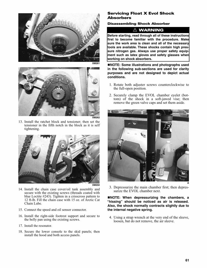
XM261
XM262
13. Install the ratchet block and tensioner; then set thetensioner in the fifth notch in the block as it is selftightening.
XM202
14. Install the chain case cover/oil tank assembly andsecure with the existing screws (threads coated withblue Loctite #243). Tighten in a crisscross pattern to12 ft-lb. Fill the chain case with 15 oz. of Arctic CatChain Lube.
15. Connect the speed and oil sensor connector.
16. Install the right-side footrest support and secure tothe belly pan using the existing screws.
17. Install the resonator.
18. Secure the lower console to the skid panels; theninstall the hood and both access panels.
Servicing Float X Evol Shock Absorbers
Disassembling Shock Absorber
NOTE: Some illustrations and photographs usedin the following sub-sections are used for claritypurposes and are not designed to depict actualconditions.
1. Rotate both adjuster screws counterclockwise tothe full-open position.
2. Securely clamp the EVOL chamber eyelet (bot-tom) of the shock in a soft-jawed vise; thenremove the green valve caps and set them aside.
A
3. Depressurize the main chamber first; then depres-surize the EVOL chamber next.
NOTE: When depressurizing the chambers, a“hissing” should be noticed as air is released.Also, the shock normally contracts slightly due tothe internal negative spring.
4. Using a strap wrench at the very end of the sleeve,loosen, but do not remove, the air sleeve.
! WARNINGBefore starting, read through all of these instructionsfirst to become familiar with the procedure. Makesure the work area is clean and all of the necessarytools are available. These shocks contain high pres-sure nitrogen gas. Always use proper safety equip-ment such as latex gloves and safety glasses whenworking on shock absorbers.
61

B
5. Remove the shock from the vise, invert it, andclamp it in the vise by the reservoir eyelet.
6. Unthread the air sleeve from the EVOL chamberby hand and slide it down the body.
C
NOTE: Look for oil in the air chamber which maybe at the top of the bearing head assembly. Thereshould be a small amount of assembly lube (blue)present, but any indication of shock oil (red) indi-cates worn shaft seals.
D
7. Using a 5/64-in. hex key, remove the button screwfrom the nitrogen pellet valve.
E
8. Using a FOX nitrogen safety needle, press itthrough the rubber pellet to depressurize the nitro-gen charge. When the shock is fully discharged,pull the needle away in a straight, smooth motion.
NOTE: At this point, inspect the nitrogen valvefor signs of wear such as holes on the face of thepellet. Replace if necessary.
62

F
9. Press down on the reservoir end cap; then using ascribe or a pick tool, remove the reservoir snapring. Pull the end cap out of the reservoir.
G
H
10. Using a 5/64-in. hex key, carefully loosen thebleed set screw; then remove the ball bearing andset it aside.
I
NOTE: It is advisable to use a small magnet toremove the ball bearing from the hole.
J
11. Using an appropriate bearing head removing tool,unscrew the bearing head assembly from the shock.
K
12. Grasp the EVOL chamber end (bottom) of theshock; then gently pull the piston/shaft/bearing/EVOL free from the shock body. Set this entireassembly aside.
63

L
M
13. Remove the air sleeve from the reservoir end ofthe shock.
N
14. Using a scribe or pick tool, remove the “samurai”and back-up seals from the air sleeve.
O
P
15. Pour the shock oil out of the shock body; thenclamp the “piggy-back” body assembly in the vise.
Q
CAUTIONCare must be taken not to score or damage any of thealuminum sealing surfaces.
64

R
16. Using an appropriate IFP removing tool, removethe IFP from the “piggy-back” body.
S
17. Remove the IFP bleed screw and set aside.
T
18. Using the new seals from the appropriate sealrebuild kit, replace all IFP seals.
U
V
19. Pour the shock oil out of the “piggy-back” bodyassembly.
65

W
20. Using a 5/8-in. wrench, remove the LSC assemblyfrom the eyelet, thoroughly clean the assembly,replace the O-rings, and install the assembly intothe eyelet. Tighten to 14 ft-lb.
X
Y
Replacing Air Sleeve DU Bushing
NOTE: The DU bushing must be replaced if it issignificantly worn or damaged.
Z
1. Using an appropriately-sized IFP removing tool,insert the tool with a “delrin rod” (or a suitablesubstitute) into the air sleeve and strike the rodwith a hammer freeing the bushing.
AA
BB
66
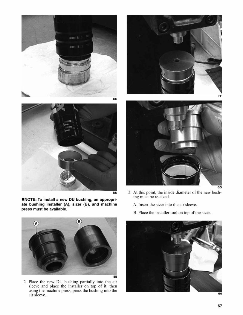
CC
DD
NOTE: To install a new DU bushing, an appropri-ate bushing installer (A), sizer (B), and machinepress must be available.
EE
2. Place the new DU bushing partially into the airsleeve and place the installer on top of it; thenusing the machine press, press the bushing into theair sleeve.
FF
GG
3. At this point, the inside diameter of the new bush-ing must be re-sized.
A. Insert the sizer into the air sleeve.
B. Place the installer tool on top of the sizer.
HH
67

C. Using the machine press, press the stack untilthe sizer falls free within the air sleeve. Removethe installer and the sizer.
II
4. Apply an ample amount of petroleum grease to the“samurai” and backup seals; then place them intothe air sleeve.
JJ
KK
NOTE: At this point, apply an ample amount ofpetroleum grease around the inside lip of the airsleeve; then set the sleeve aside.
LL
Disassembling Shaft Assembly
1. Using a 9/16-in. wrench, remove the shaft lock nut.
MM
2. Using a scribe or pick tool, lift the piston andvalve assembly collectively off the shaft.
NN
OO
68

NOTE: It is advisable to use cable ties to pre-serve the upper and lower shim stack/piston order.
PP
3. Using a sharp blade, cut the piston band; thenremove the band and discard.
RR
NOTE: Care should be taken not to scratch thepiston when cutting the band.
4. Remove the O-ring from the piston.
SS
5. Install a new piston O-ring; then using an appro-priate piston band installation tool, install a newband.
TT
6. Remove the spring from the assembly; thenremove the bearing assembly.
UU
69

VV
7. Remove and replace all O-rings and seals.
WW
XX
YY
NOTE: It may be advisable to use a cable tie to aidin removing the main seal.
ZZ
NOTE: When installing the main seal, assure that itis oriented correctly.
AAA
Rebuilding EVOL Reservoir
1. Install a new O-ring in the rebound eyelet assembly.
BBB
2. Remove the EVOL reservoir from the rebound eyelet
assembly; then install a new reservoir O-ring.
70

CCC
DDD
3. Using a shock absorber hand air pump, apply light pres-
sure to the reservoir to extract the IFP.
EEE
4. Pour approximately 2 cc of float fluid into the res-ervoir (down its side) to provide lubrication forinstalling the IFP.
FFF
5. Replace the IFP seal; then amply lubricate the IFP and
place it into the reservoir.
GGG
6. Thread the EVOL reservoir onto the rebound eyelet; then
tighten to 12 ft-lb.
Assembling Shaft Assembly
1. With the shaft assembly clamped in the vise, install the
bottom-out bumper.
HHH
2. Place the Bearing Cap Seal Protector (p/n 0644-268) onto the shaft, amply lubricate the protector,and install the bearing assembly onto the shaft.
71

III
3. Install the lower and upper shim stack/piston assembly.
JJJ
NOTE: Care must be taken that the preserved shimstack/piston assembly be installed correctly.
4. Thread the lock nut onto the shaft; then tighten to 18 ft-lb.
Set the shaft assembly aside.
KKK
Assembling Shock Absorber
1. Securely clamp the “piggy-back” body assembly in the
vise; then using an appropriate air sleeve protector tool,
slide the air sleeve over the body.
LLL
MMM
72
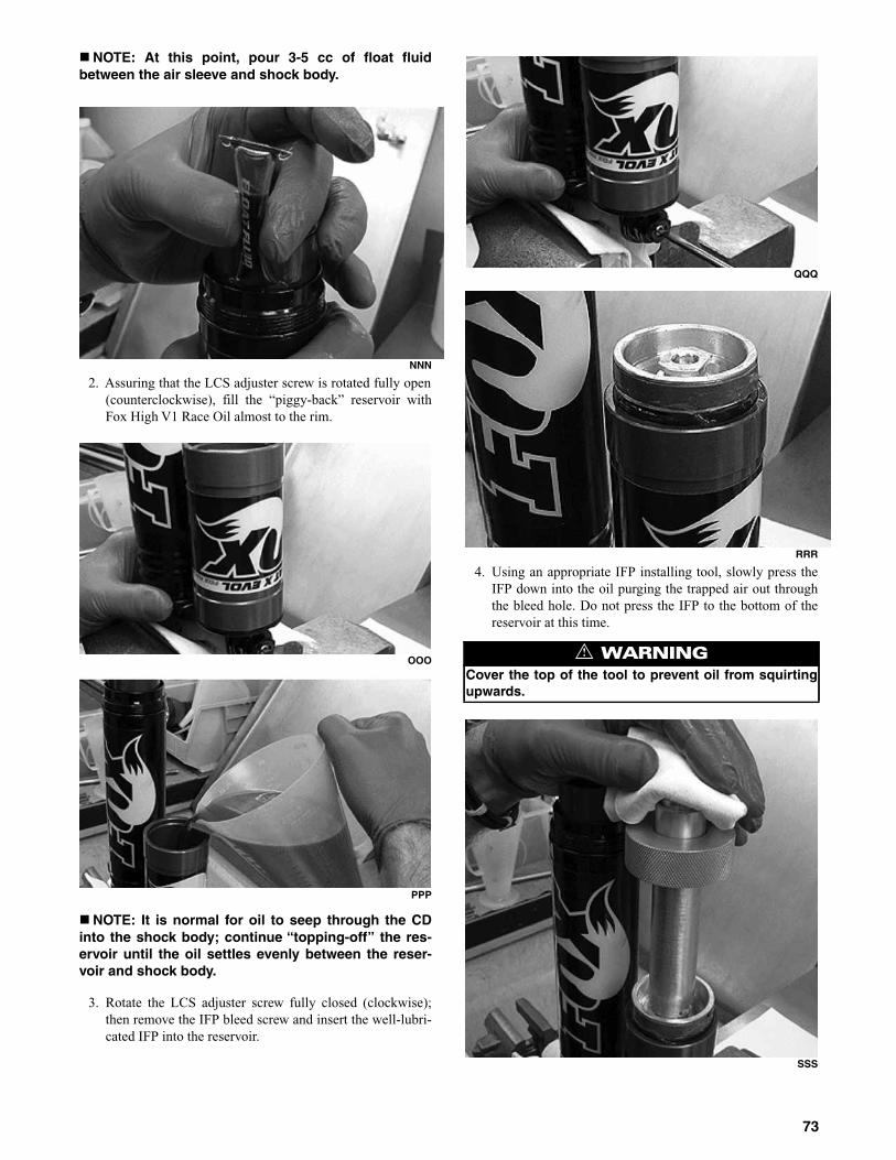
NOTE: At this point, pour 3-5 cc of float fluidbetween the air sleeve and shock body.
NNN
2. Assuring that the LCS adjuster screw is rotated fully open
(counterclockwise), fill the “piggy-back” reservoir with
Fox High V1 Race Oil almost to the rim.
OOO
PPP
NOTE: It is normal for oil to seep through the CDinto the shock body; continue “topping-off” the res-ervoir until the oil settles evenly between the reser-voir and shock body.
3. Rotate the LCS adjuster screw fully closed (clockwise);
then remove the IFP bleed screw and insert the well-lubri-
cated IFP into the reservoir.
QQQ
RRR
4. Using an appropriate IFP installing tool, slowly press the
IFP down into the oil purging the trapped air out through
the bleed hole. Do not press the IFP to the bottom of the
reservoir at this time.
SSS
! WARNINGCover the top of the tool to prevent oil from squirtingupwards.
73

TTT
5. Install the IFP bleed screw.
UUU
NOTE: It is allowable to leave some oil trapped inthe reservoir above the piston.
6. Using the IFP installing tool, press the IFP to the bottom
of the reservoir; then pull the IFP back 2 in. from the top
of the reservoir.
NOTE: Repeat this procedure several times toassure a full bleed; then position the IFP approxi-mately 1 in. from the bottom of the reservoir.
VVV
WWW
7. Assuring that the LCS adjuster screw is rotated fully open
(counterclockwise), fill the shock body with Fox High V1
Race Oil; then rotate the LCS adjuster screw fully closed
(clockwise).
XXX
8. Back out the rebound adjuster on the shaft assem-bly; then by inserting the long end of an Allenwrench into the shaft post, depress the meteringrod lightly until the metering rod moves awayfrom the jet.
9. While holding the negative spring and spacer atthe top of the shaft with one hand, insert the shaftand bearing assembly into the shock lower takingcare not to spill oil into the air sleeve. Very slowlypush the shaft down into the oil while rotating and“wiggling” the shaft until there are no bubbles ris-ing in the oil.
74

YYY
10. Using a rubber mallet, gently tap the shaft to allow trapped
air to escape from between the piston and valve shims.
ZZZ
11. Gently lower the negative spring and spacer into the oil
taking care not to let the oil overflow into the air sleeve.
12. Carefully lower the bearing assembly into thedamping body and thread into the shock; thenusing an appropriate bearing head tool, tighten thebearing assembly to 50 ft-lb.
AAAA
BBBB
13. Slide the air sleeve up to be flush with the bearing head
assembly to prevent oil from spilling into the air sleeve.
Gently compress the IFP to purge the last air bubbles from
the body out the bleed screw. Make sure the shaft is fully
extended to the point of it contacting the negative spring.
CAUTIONMake sure the piston assembly and the rebound holein the shaft DO NOT come out of the oil bath. If therebound adjust hole in the shaft comes out of the oilbath, air can transfer to the underside of the pistonaerating the shock. Add oil to the shock as required tokeep the hole covered. Pull the shaft assembly out ofthe oil until the top of the negative spring is even withthe end of the body.
75

CCCC
DDDD
14. Install the bleed set screw; then using a 5/64 in. hex key,
tighten the set screw.
EEEE
FFFF
15. Slide the air sleeve down far enough to liberally lubricate
the bearing head assembly.
GGGG
16. To set the IFP depth, remove the bleed screw; then using
Floating Piston Location Gauge (p/n 0644-350), adjust the
depth to 2.5 in. Install the bleed screw.
HHHH
17. Pour the excess oil from the IFP reservoir, installthe reservoir end cap pressing it down firmly, andinstall the snap ring.
IIII
76

JJJJ
KKKK
18. Using an appropriate inflation needle, charge thereservoir to 250 psi (p/n 3703-064/065).
19. Using an appropriate strap wrench, tighten the airsleeve into the rebound eyelet assembly.
LLLL
20. Using a high-pressure hand air pump, pressurizethe shocks to 200 psi EVOL and 80 psi Main.
MMMM
NNNN
Rear Suspension
The Sno Pro 600 is equipped with a compression adjust-able remote reservoir shock in the rear suspension sys-tem. This system utilizes front arm limiter straps.
The suspension should be adjusted for the operationalneeds and riding preference of the operator.
The rear springs influence the load carrying capabilityof the snowmobile and should be adjusted for theweight and riding preference of the operator.
Rear Arm Shock Rebound
The rear arm shock can be adjusted for rebound quali-ties. To adjust, use the following procedure.
1. Turn the adjuster clockwise until it stops (hardposition).
2. Turn the adjuster counterclockwise to the initialsetting (see appropriate Valve Stacks/Specifica-tions page in this manual) or turn the adjustercounterclockwise the desired number of “clicks.”
NOTE: On the rear arm shock, the reboundadjuster has a total range of 18 “clicks” or 4 1/2 fullturns (4 “clicks”= 1 turn).
77

Front/Rear Arm Shock Compression
1. Turn the adjuster clockwise until it stops (hardposition).
2. Turn the adjuster counterclockwise to the initial setting(see page 9 in this manual) or turn the adjuster counter-clockwise the desired number of “clicks.”
NOTE: On the rear arm shock, the compressionadjuster has a total range of 18 “clicks” or 3 fullturns (6 “clicks” = 1 turn).
Front Arm Shock Spring
The skid frame front arm shock spring is adjustable.However, Arctic Cat recommends that the shockspring be adjusted to a maximum of 6.4 mm (1/4 in.)up or down from the standard pre-load setting.
NOTE: The standard pre-load spring length (installed)is 7.64 in.
When customizing the amount of ski pressure, be sure tonot over-adjust the front arm shock spring to adverselyaffect steering and operator control of the snowmobile.Some experimentation may be required until the properadjustment for the operator’s individual style is obtained.
NOTE: Each driver’s style is different and someexperimentation will be required to become famil-iar with the above adjustment procedure.
Adjusting Rear Spring Tension
Rear spring tension adjustment is accomplished by rotat-ing the adjusting cams. Position 3 provides the stiffest ride,and position 1 provides the softest ride. Always rotate thecam from the lighter position to the heavier position.
To rotate an adjusting cam, use a six-point box-endwrench. Rotate the wrench until the cam is in thedesired position. To stiffen the ride, rotate the cam soas to raise the spring end. Make the adjustment on theother cam and be sure both cams are adjusted equally.
Servicing Zero-X Shock Absorbers
This procedure shows the proper method for servicingthe front arm shock absorber w/“piggy-back” reservoir.
NOTE: Some illustrations and photographs usedin the following sub-sections are used for claritypurposes and are not designed to depict actualconditions.
Disassembling
1. Remove the bearings and retaining rings from theeyelets.
2. Clean the entire shock assembly with soapy water.Dry the shock assembly with compressed air.
NOTE: If compressed air is not available, useclean towel to dry the shock assembly.
3. Clamp the shock body eyelet securely in a soft-jawed vise and remove the ball from the end cap;then using a 3/16-in. hex key, slowly loosen the setscrew (FAV3 valve) on the shock reservoir.
FS383
CAUTIONDo not exceed the maximum 6.4 mm (1/4 in.) up ordown from the standard pre-load setting.
! WARNINGDo not adjust the front arm shock to a point at whichsteering and operator control of the snowmobile areadversely affected.
! WARNINGDO NOT make adjustments while operating the snow-mobile. Keep both hands on the handlebar while thesnowmobile is moving.
CAUTIONNever force the adjustment cams from the low posi-tion to the high position. Cam damage may occur.
! WARNINGBefore starting, read through all of these instructionsfirst to become familiar with the procedure. Make surethe work area is clean and all of the necessary toolsare available. These shocks contain high pressurenitrogen gas. Always use proper safety equipmentsuch as latex gloves and safety glasses when workingon shock absorbers.
CAUTIONUse a soft-bristle brush to remove as much dirt anddebris as possible. Do not pressure wash the shockas this can force water and debris inside causing dam-age to the seals.
! WARNINGWhen using compressed air to dry components,always wear safety glasses.
! WARNINGAlways place a rag or towel over the valve and hex keyfor protection when releasing the nitrogen from thereservoir.
78
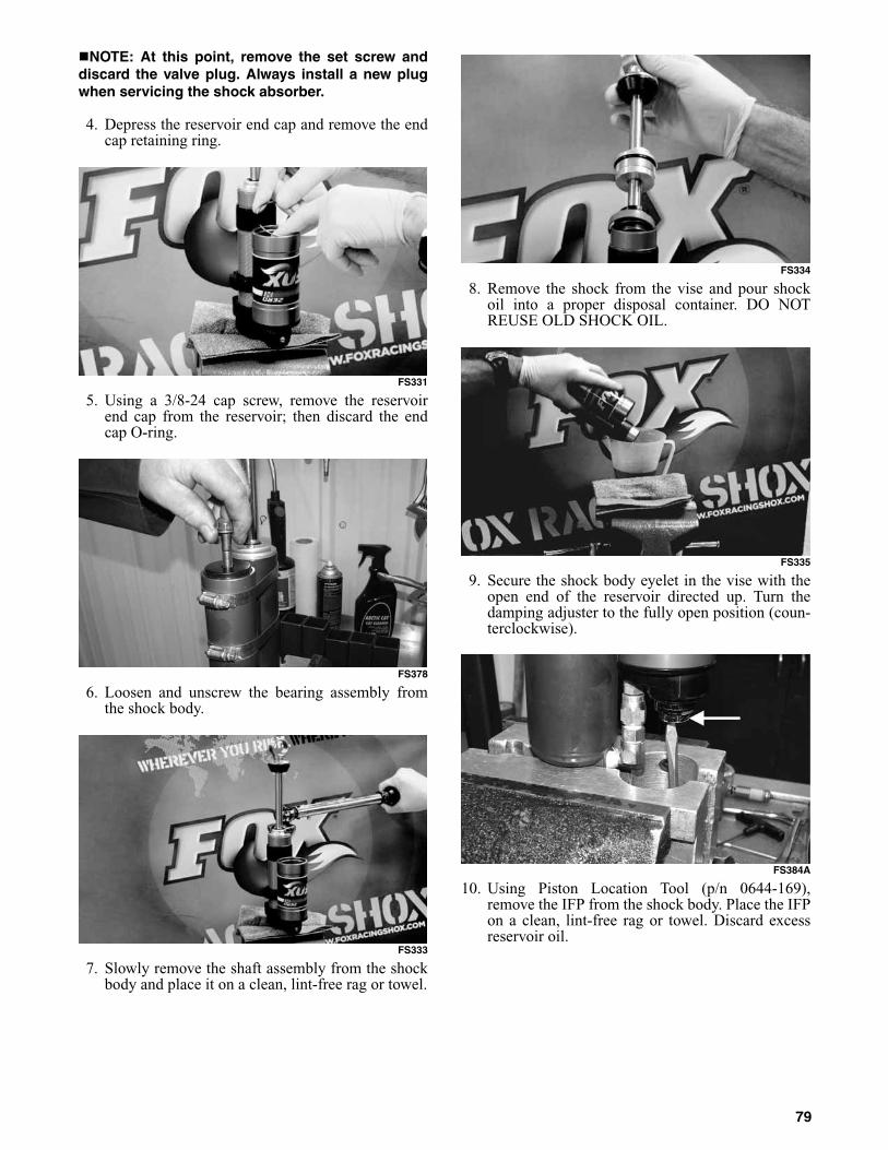
NOTE: At this point, remove the set screw anddiscard the valve plug. Always install a new plugwhen servicing the shock absorber.
4. Depress the reservoir end cap and remove the endcap retaining ring.
FS331
5. Using a 3/8-24 cap screw, remove the reservoirend cap from the reservoir; then discard the endcap O-ring.
FS378
6. Loosen and unscrew the bearing assembly fromthe shock body.
FS333
7. Slowly remove the shaft assembly from the shockbody and place it on a clean, lint-free rag or towel.
FS334
8. Remove the shock from the vise and pour shockoil into a proper disposal container. DO NOTREUSE OLD SHOCK OIL.
FS335
9. Secure the shock body eyelet in the vise with theopen end of the reservoir directed up. Turn thedamping adjuster to the fully open position (coun-terclockwise).
FS384A
10. Using Piston Location Tool (p/n 0644-169),remove the IFP from the shock body. Place the IFPon a clean, lint-free rag or towel. Discard excessreservoir oil.
79

FS337
FS339
11. Remove the relief screw from the IFP. Discard therelief screw O-ring, IFP O-ring, and the IFP strap.
FS338
12. Clean and dry the IFP; then secure the shock bodyeyelet in the vise. Do not over-tighten the vise.
FS340
13. Using a 5/8-in. socket, remove the dampingadjuster cartridge; then clean and inspect theinboard and outboard O-rings.
FS292A
NOTE: At this point, inspect the re-flow checkvalve for smooth operation and for not being bentor deformed.
FS380A
14. Install the cartridge; then tighten to 20 ft-lb.
FS381
15. Clamp the shaft eyelet securely in vise with thepiston end up.
CAUTIONCare must be taken not to scratch the cartridge whenremoving O-rings.
80

FS343
16. Using a 9/16-in. wrench, remove the piston nutfrom the end of the shaft.
FS344
17. Slide the piston assembly onto a T-handle wrenchto preserve the shim stack/piston order. Removeand discard the step-cut piston strap and O-ring.
18. Remove the piston, bearing assembly, and spacer.Inspect and/or replace the bottom out bumper ifnecessary.
FS346
Assembling
1. Place Bearing Cap Seal Protector (p/n 0644-268)onto the end of the shaft; then apply grease to boththe tool and the shaft.
FS348
2. Slide the bearing assembly over the protector toolonto the shaft.
FS349
3. Install a new piston O-ring and step-cut pistonstrap.
4. Place the preserved shim stack/piston assemblyonto the shaft; then using a 9/16-in. socket, installthe piston nut and tighten to 18 ft-lb.
FS350
81

FS351
5. Place the shock body and eyelet in the vise withthe open end directed up.
6. Fill the reservoir with Shock Oil (p/n 5639-240)until approximately 3/4 full.
NOTE: Allow a few minutes for oil to overflowinto the shock body.
FS352
7. Turn the damping adjuster to the fully closed posi-tion (clockwise); then refill the reservoir untilapproximately 3/4 full.
FS353
8. Lightly grease the IFP; then slowly insert the IFPinto the reservoir and press until the IFP is levelalong the flat end of the reservoir.
FS354
9. Install Floating Piston Location Gauge (p/n 0644-350) and cover the top of the tool with a towel; thenslowly press the IFP into the oil until fully covered.
FS355
FS356
10. Install the IFP relief screw making sure to seat therelief screw O-ring. Do not tighten.
FS357
82

11. Turn the damping adjuster to the fully open posi-tion (counterclockwise).
FS358
12. Using the IFP location gauge, slowly stroke theIFP in the reservoir several times to purge air frombetween the reservoir and shock body. Repeat thisprocess until no air bubbles rise through the oil inthe body. Do not expose the IFP above the oil sur-face.
FS359
13. Depress the IFP to its lowest position; then pull theIFP to approximately 1 1/2 in. from the top of thereservoir.
FS360
14. Turn the damping adjuster to the fully closed posi-tion (clockwise).
15. Fill the shock body to approximately 1 in. from thetop with recommended shock oil.
FS361
16. Install new O-rings and piston strap on the pistonshaft assembly and lightly grease the piston strap;then insert the piston shaft assembly into the shockbody holding the bearing up by the shaft eyelet.
FS362
NOTE: Slowly in a circular motion, stroke the pis-ton in the shock body tapping the shaft downwardwith a rubber hammer on the down stroke. Repeatthis process several times until the air is purgedfrom the shim stack/piston assembly.
FS363
17. Fully extend the shaft without exposing the pistonto air; then refill with recommended oil untilapproximately 1 in. from the top or to where thethreads for the bearing end.
83

FS364
18. While holding the shaft fully extended, slide theassembly into the shock body.
NOTE: At this point, oil should overflow. If not,add recommended oil.
FS365
19. Using a torque wrench with a 1-in. crow-foot,tighten the bearing assembly to 35 ft-lb.
FS367
20. Remove the IFP relief screw; then set the IFP loca-tion gauge to 1.9 in. measured from the top end ofthe reservoir.
FS368
FS369
21. While holding the IFP with the location gauge,install and tighten the relief screw.
FS370
22. Discard the excess oil remaining above the IFP.
FS371
23. Lubricate and install the IFP reservoir end cap O-ring. Install the reservoir end cap and retainingring. Ensure proper seating.
84

FS373
24. Install the set screw (FAV3 valve assembly) andtighten only until snug; then loosen two turns.
25. Insert the needle squarely into the center of thenitrogen valve set screw and plug (taking care thatthe valve is directed away from face and body) andpressurize the reservoir to 250 psi.
FS374
26. Using a 3/16-in. hex key, tighten the set screw(FAV3 valve) on the shock reservoir; then install anew ball.
FS329
FS376
27. Install the bearings and retaining rings into the eyelets.
NOTE: Ensure proper shock function prior toinstalling on the snowmobile.
Adjusting Rear Transfer Adjuster Cams
The transfer system has seven positions. To make camadjustment, use the following procedure.
0741-231A
1. Loosen the Cap Screw (p/n 8020-040) and LockNut (p/n 8047-366) securing the cams to the sliderail. Remove the cap screw.
2. Using a 1/4-in. drive ratchet and extension, rotatethe cams to the desired position.
NOTE: Position 1 allows for the most weight trans-fer, and position 7 allows for the least weight transfer.
NOTE: When setting the cams, the chosen posi-tion must be directed toward the rear arm.
NOTE: Standard cam position is position 1.
3. Install the cap screw and lock nut to secure thecam position; then tighten securely.
Lights
Removing Headlight Assembly
1. Remove the four screws securing the windshield tothe console; then remove the windshield.
2. Remove the four screws securing the windshieldbrace to the console. Disconnect the gauge; thenremove the windshield brace assembly.
3. Disconnect the electrical accessory wires and igni-tion switch.
! WARNINGCharge the shock using nitrogen gas only. DO NOTCHARGE WITH ANY OTHER TYPE OF GAS. Doing sowill compromise the performance of the shock andmay be EXTREMELY DANGEROUS.
85

4. Remove the two screws securing the rear of the con-sole to the hood.
5. Lift the front of the console from the headlightassembly; then disengage the side console tabs andremove the console.
PC108
6. Loosen the two side headlight assembly screws (A);then remove the two front headlight assembly screws(B).
PC107A
7. Remove the headlight assembly.
Removing/Installing Headlight Bulb
NOTE: The bulb portion of the headlight is fragile.HANDLE WITH CARE. When replacing the headlightbulb, the bulb assembly must first be removed fromthe housing. Do not touch the glass portion of thebulb. If the glass is touched, it must be cleaned with adry cloth before installing.
1. Disconnect the headlight harness connector from thebulb; then remove the rubber grommet from theheadlight housing.
2. Rotate the bulb retainer counterclockwise until itunlocks from the housing; then remove the bulb.
0746-096
3. Install the bulb and retainer; then rotate the retainerclockwise until it properly locks in place.
4. Install the rubber grommet; then connect the head-light harness connector to the bulb.
5. Check headlight aim (see Adjusting Headlight Aimin this sub-section).
Installing Headlight Assembly
1. With the headlight assembly in position, install thefront headlight assembly screws. Engage the sideheadlight screws in the slots and tighten until snug.
2. Engage the side console tabs on the headlight assem-bly; then place the front of the console over the head-light assembly. and press down until it snaps in place.
3. Install the two screws securing the rear of the con-sole to the hood. Tighten only until snug.
4. Place the windshield brace assembly into positionand secure to the console with the four screws.Tighten until snug.
5. Connect the gauge; then connect the electricalaccessory wires.
6. With the windshield in position, secure the windshieldto the frame using the four screws. Tighten securely.
Ski Wear Bar
The ski wear bar is a replaceable bar attached to theunderside of the ski. The purpose of the wear bar is toassist in turning the snowmobile, to minimize ski wear,and to maintain good steering control. If the snowmo-bile is operated primarily in deep snow, ski wear barwear will be minimal; however, if the snowmobile isoperated on terrain where the snow cover is minimal,the ski wear bar will wear faster. To maintain positivesteering characteristics, Arctic Cat recommends thatthe ski wear bars be checked before each use andreplaced if worn beyond 1/2 of the original diameter.Ski wear bars are available from an authorized ArcticCat Snowmobile dealer.
NOTE: Always check the official rules for theappropriate wear bars for the event being partici-pated in.
Removing
1. Raise the front of the snowmobile and place it on asupport stand.
! WARNINGDo not operate the snowmobile unless headlight beamis adjusted properly. An incorrectly adjusted beam willnot provide the operator the optimum amount of light.
! WARNINGOperating the snowmobile with excessively worn ormissing wear bars may result in a loss of steering con-trol.
86
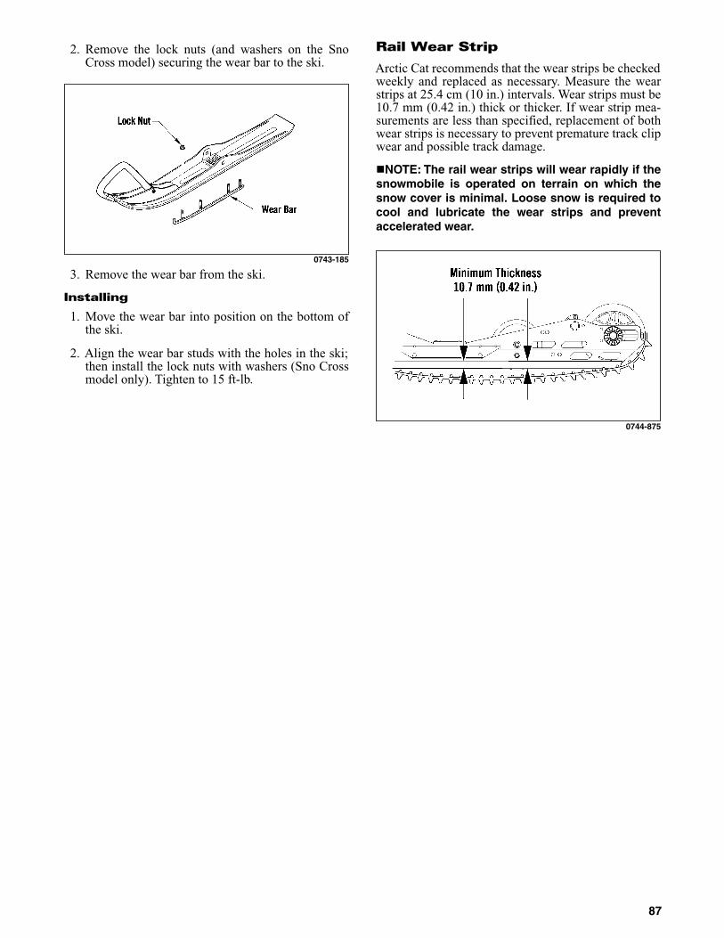
2. Remove the lock nuts (and washers on the SnoCross model) securing the wear bar to the ski.
0743-185
3. Remove the wear bar from the ski.
Installing
1. Move the wear bar into position on the bottom ofthe ski.
2. Align the wear bar studs with the holes in the ski;then install the lock nuts with washers (Sno Crossmodel only). Tighten to 15 ft-lb.
Rail Wear Strip
Arctic Cat recommends that the wear strips be checkedweekly and replaced as necessary. Measure the wearstrips at 25.4 cm (10 in.) intervals. Wear strips must be10.7 mm (0.42 in.) thick or thicker. If wear strip mea-surements are less than specified, replacement of bothwear strips is necessary to prevent premature track clipwear and possible track damage.
NOTE: The rail wear strips will wear rapidly if thesnowmobile is operated on terrain on which thesnow cover is minimal. Loose snow is required tocool and lubricate the wear strips and preventaccelerated wear.
0744-875
87

Performance Tips
Operating a high performance snowmobile requires aspecial attention. Often, a minor adjustment will result ina large increase in performance. This section is intendedto highlight minor conditions that adversely affect per-formance and the adjustments needed to correct them. Besure, however, to thoroughly read and understand thisentire manual especially the section on spark plugs, tracktension and alignment, and suspension.
DRIVE BELT — This link between the engine anddrive train is often the most neglected component. Thedrive belt must have the proper fit in the drive clutchand driven clutch. Proper fit is when the top surface ofthe drive belt is flush with the top or up to 1/16 in.higher than the driven clutch sheaves (with the sheavesfully closed). If the belt sits below this level, the snow-mobile will bog at slow speeds and will have a slowermaximum speed. To correct this condition, first deter-mine if the drive belt is within specifications (seeDrive Belt section) and replace if worn or too long.Secondly, always run the drive belt in the same direc-tion. Installing the drive belt so the part number can beread will ensure that the drive belt is always run thesame direction.
DRIVE CLUTCH AND DRIVEN CLUTCH —Keeping the drive clutch and driven clutch cleanshould be the primary consideration of the operator.The clutch sheaves can be cleaned of any drive beltaccumulation using a clean cloth and parts-cleaningsolvent. All pivot points can be maintained clean usingcompressed air.
CARBURETOR MAIN JETS — Proper carburetion,specifically proper main jets, is absolutely necessary toobtain peak performance. Since ambient temperatureand operating altitude both affect the main jet sizeneeded for optimum engine performance, the main jetswill often need to be changed whenever the tempera-ture changes 20° F (11° C) or whenever operating alti-tude varies by more than 1000 feet.
CAUTIONUse Clutch Puller (p/n 0744-062). Never substitute adifferent puller or drive clutch damage will occur.
88

Preparation For Storage
Prior to storing the snowmobile, it must be properlyserviced to prevent corrosion and component deterio-ration. To prepare the snowmobile for storage, ArcticCat recommends the following procedure.
1. Clean the seat cushion with a damp cloth and Arc-tic Cat Vinyl Protectant.
2. Clean the snowmobile thoroughly by hosing dirt,oil, grass, and other foreign matter from the skidframe, tunnel, hood, and belly pan. Allow thesnowmobile to dry thoroughly. DO NOT get waterinto any part of the engine.
3. Place the rear of the snowmobile up on a shieldedsafety stand. Remove the air-intake silencer bootsfrom the carburetors.
4. Start the engine and allow to idle. With the engineidling, spray an Engine Storage Preserver into thecarburetors until the engine exhaust starts tosmoke heavily or until the engine starts to drop inRPM. Turn engine off.
5. Plug the exhaust system outlet with a clean cloth.
6. With the tether switch cap removed:
A. Disconnect the high tension leads from thespark plugs; then remove the plugs, connectthem to the leads, and ground them on the cyl-inder heads.
B. Pour 29.5 ml (1 fl oz) of SAE #30 petroleum-based oil into each spark plug hole and pull therecoil starter handle slowly about 10 times.
C. Install the spark plugs and connect the high ten-sion leads.
7. Drain the gas from the carburetor float bowls. Fillthe gas tank to its rated capacity; then add ArcticCat Fuel Stabilizer (p/n 0436-907) to the gas tankfollowing directions on the container for the stabi-lizer/gasoline ratio. Tighten the gas tank capsecurely.
8. Drain the chain-case lubricant. Remove the chain-case cover and inspect chain, sprockets, and chaintensioner for wear and the chain for proper ten-sion. Install the chain-case cover and seal; thenpour Arctic Cat Synthetic Chain Lube (p/n 5639-038) into the oil level stick filler hole according tospecifications.
9. Remove the drive belt from the drive clutch/drivenclutch. Lay the belt on a flat surface or slide it intoa cardboard sleeve to prevent warping or distortionduring storage.
10. Clean and inspect the drive clutch and drivenclutch.
11. Apply light oil to the upper steering post bushingand shafts of the shock absorbers.
12. Lubricate the rear suspension and bellcranks witha all-temperature grease.
13. Tighten all nuts, bolts, and cap screws making sureall calibrated nuts, bolts, and cap screws are tight-ened to specifications. Make sure all rivets holdingthe components together are tight. Replace allloose rivets.
14. Clean and polish the hood, console, and chassiswith Cat Cleaner (p/n 4639-371). DO NOT USESOLVENTS. THE PROPELLANT WILL DAM-AGE THE FINISH.
15. If possible, store the snowmobile indoors. Raisethe track off the floor by blocking up the back endmaking sure the snowmobile is secure. Loosen thetrack adjusting bolts to reduce track tension. Coverthe snowmobile with a machine cover or a heavytarpaulin to protect it from dirt and dust.
16. If the snowmobile must be stored outdoors, posi-tion the snowmobile out of direct sunlight; thenblock the entire snowmobile off the ground mak-ing sure the snowmobile is secure. Loosen thetrack adjusting bolts to reduce track tension. Coverwith a machine cover or a heavy tarpaulin to pro-tect it from dirt, dust, and rain.
CAUTIONNever crank the engine over without grounding thespark plugs. Damage to coils and/or CDI unit mayresult.
CAUTIONAvoid storing in direct sunlight and using a plasticcover as moisture may collect on the snowmobilecausing corrosion.
89
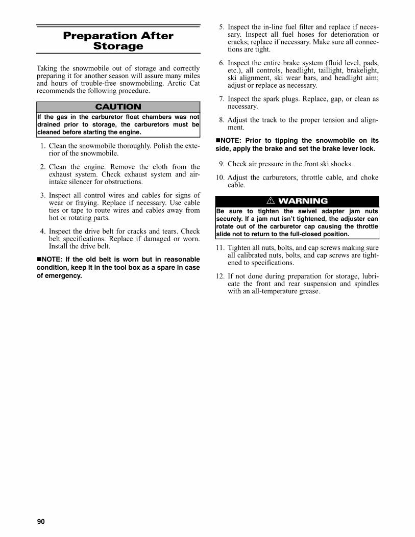
Preparation After Storage
Taking the snowmobile out of storage and correctlypreparing it for another season will assure many milesand hours of trouble-free snowmobiling. Arctic Catrecommends the following procedure.
1. Clean the snowmobile thoroughly. Polish the exte-rior of the snowmobile.
2. Clean the engine. Remove the cloth from theexhaust system. Check exhaust system and air-intake silencer for obstructions.
3. Inspect all control wires and cables for signs ofwear or fraying. Replace if necessary. Use cableties or tape to route wires and cables away fromhot or rotating parts.
4. Inspect the drive belt for cracks and tears. Checkbelt specifications. Replace if damaged or worn.Install the drive belt.
NOTE: If the old belt is worn but in reasonablecondition, keep it in the tool box as a spare in caseof emergency.
5. Inspect the in-line fuel filter and replace if neces-sary. Inspect all fuel hoses for deterioration orcracks; replace if necessary. Make sure all connec-tions are tight.
6. Inspect the entire brake system (fluid level, pads,etc.), all controls, headlight, taillight, brakelight,ski alignment, ski wear bars, and headlight aim;adjust or replace as necessary.
7. Inspect the spark plugs. Replace, gap, or clean asnecessary.
8. Adjust the track to the proper tension and align-ment.
NOTE: Prior to tipping the snowmobile on itsside, apply the brake and set the brake lever lock.
9. Check air pressure in the front ski shocks.
10. Adjust the carburetors, throttle cable, and chokecable.
11. Tighten all nuts, bolts, and cap screws making sureall calibrated nuts, bolts, and cap screws are tight-ened to specifications.
12. If not done during preparation for storage, lubri-cate the front and rear suspension and spindleswith an all-temperature grease.
CAUTIONIf the gas in the carburetor float chambers was notdrained prior to storage, the carburetors must becleaned before starting the engine.
! WARNINGBe sure to tighten the swivel adapter jam nutssecurely. If a jam nut isn’t tightened, the adjuster canrotate out of the carburetor cap causing the throttleslide not to return to the full-closed position.
90
Genuine Arctic Cat Products
Arctic Cat Oil - Developed, tested, and proven espe-cially for Arctic Cat Snowmobile engines. Arctic CatOil is the only oil authorized by Suzuki and Arctic Catengineers for use in Arctic Cat Snowmobile engines.Arctic Cat Oil ensures warranty coverage for lubricat-ing related incidents. Arctic Cat Oil comes in strong,handy, recloseable containers.
Transmission Lube - A special formula that reducesfriction and fights corrosion. Arctic Cat TransmissionLube comes in easy-pour, recloseable containers.
Synthetic Chain Lube - A special formula reducesfriction and fights chain case corrosion.
Fuel Stabilizer - Fuel treatment for storage longerthan 60 days. Slows oxidation to prevent gum and var-nish buildup. Engines start easily even after storageperiods exceeding one year. Ideal for use in snowmo-bile gas tanks.
Antifreeze - Pre-mixed ready for use without addingany water. Comes in 1 gallon container.
Hi-Temp Brake Fluid - Recommended for Arctic Cathydraulic brake system.
Product ContainerSize
PartNumber
Pkg/Qty
Synthetic APV 2-Cycle Oil 55 gal. 2639-509 1
Synthetic APV 2-Cycle Oil 1 gal. 2639-511 6/1 gal.
Synthetic APV 2-Cycle Oil 16 gal. 2639-510 1
Synthetic APV 2-Cycle Oil 2-1/2 gal. 2639-975 2—2-1/2 gal.
Synthetic APV 2-Cycle Oil 1 qt 2639-512 12/1 qt.
Synthetic Chain Lube 8 oz 5639-038 –
Transmission Lube 12 oz 0636-817 12/12 oz
Engine Storage Preserver 12 oz 0436-888 12/12 oz
All-Temp Grease (Lithium) 14-1/2 oz 4639-365 10/14-1/2 oz
Silicone Spray 10 oz 0636-594 12/10 oz
Shock Oil - Light (Fox Racing) 1 qt 4639-345 1 qt
Fuel Stabilizer 8 oz 0436-907 12/8 oz
Hi-Temp Brake Fluid 12 oz 0436-908 6/12 oz
Antifreeze 1 gal. 0436-909 6/1 gal.
Fuel System Cleaner 12 oz 3639-619 1
Race Fuel (116-Leaded) 16 gal. 3639-620 1
Race Fuel (116-Leaded) 55 gal. 3639-621 1
Race Fuel (110-Leaded) 16 gal. 2639-098 1
Race Fuel (110-Leaded) 55 gal. 2639-097 1
Race Fuel (110-Leaded) 16 gal. 2639-098 1
Race Fuel (110-Leaded) 55 gal. 2639-097 1
Race Fuel (116-Leaded) 16 gal. 3639-620 1
Race Fuel (116-Leaded) 55 gal. 3639-621 1
Shock Oil 1 qt 5639-240 1 qt
91

Special Tools
To order any special tools, call the Service Departmentat Arctic Cat Inc. 1-800-279-2281.
Ball Hone
p/n: 0644-290 (60-64 mm)p/n: 0644-291 (65-70 mm)p/n: 0644-292 (72-74 mm)p/n: 0644-293 (76-83 mm)p/n: 0644-294 (83-88 mm)p/n: 0644-531 (90-95 mm)p/n: 0644-532 (96-101 mm)p/n: 0644-533 (102-108 mm)Usage: Deglaze Nicosil plated cylinders. All are 320 gritand are recommended for reconditioning Arctic Cat snow-mobile engine cylinders.
0644-291
Flywheel Spanner Wrench
p/n: 0144-007Usage: Hold starter cup while removing/installing fly-wheel nut.
0144-007
Flywheel Puller Insert
p/n: 0644-179Usage: Protect the crankshaft end during flywheelremoval.
0644-179
Flywheel Puller
p/n: 0744-040 (Complete Set)p/n: 0643-086 (Body)p/n: 0643-087 (Bolt)p/n: 0423-482 (6 mm Cap Screw)p/n: 0423-483 (8 mm Cap Screw)Usage: Pull flywheel off crankshaft on all Arctic Cat 2-stroke models.
0744-040
Crankshaft Bearing Remover
p/n: 0144-302Usage: Remove crankshaft bearings.
0144-302
92

Oil Seal Protector Tool
p/n: 0644-219Usage: Protect the oil seal when installing the waterpump driveshaft on liquid cooled 2-stroke Arctic Catengines.
0644-219
Piston Pin Puller
p/n: 0644-328 (Complete Set)p/n: 0643-073 (Extractor Nut Only-Small)p/n: 0643-074 (Extractor Nut Only-Medium)p/n: 0643-075 (Extractor Nut Only-Large)p/n: 0643-072 (Threaded T-Handle)Usage: Remove piston pins.
0644-328
Spring Tool
p/n: 0644-554Usage: Remove/install exhaust springs.
0644-554
Spring Tool
p/n: 0644-072Usage: Remove/install exhaust springs.
0644-072
Stud Runner
p/n: 0644-018 (6 mm)p/n: 0644-019 (8 mm)p/n: 0644-020 (10 mm)Usage: Install studs on cylinders and crankcase.
0644-020
Surface Plate
p/n: 0644-016Usage: True sealing surfaces.
0644-016
93

V Blocks
p/n: 0644-535Usage: Check crankshaft runout.
0644-535
Water Pump Bearing and Seal Tool Kit
p/n: 0644-557Usage: Remove/install crankcase water pump bearingsand seals.
0644-557
Vacuum Test Pump
p/n: 0644-131Usage: Check components for air leaks.
0644-131
Compression Tester Kit
p/n: 0444-213 (Complete Kit)p/n: 0444-207 (10 mm Adapter)p/n: 0444-093 (12 mm Adapter)Usage: Test cylinder compression on all Arctic Catengines.
0444-213
Engine Timing Gauge
p/n: 0144-009Usage: Static time engines without CDI ignition.
0144-009
Timing Light
p/n: 0644-296Usage: Check ignition timing.
0644-296
94

90° Hex Driver (1/4-in.)
p/n: 0644-550Usage: Make carburetor adjustments on all twin and tri-ple cylinder engines. Also, for any hard-to-get-at hex nuts.(A. 6 mm Hex)(B. 0.157-in. D-Head)(C. 1/4-in. Drive)(D. Straight Blade)(E. Phillips-Head)
0644-550
Bearing Cap Seal Protector
p/n: 0644-268p/n: 0644-403 (1/2 in. O.D. x 3/8 in. I.D.)p/n: 0644-404 (5/8 in. O.D. x 3/8 in. I.D.)p/n: 0644-542 (5/8 in. O.D. x 1/2 in. I.D.)Usage: Protect cap seal on rebuildable shock absorbers.
0644-404
Clutch Compressor
p/n: 0644-420Usage: Compress and hold drive clutch in the com-pressed position for changing cam arms and removing/installing six-post drive clutch.
0644-420
Drive Clutch Puller (Arctic)
p/n: 0744-062Usage: Remove drive clutch from the crankshaft on2010-2012 models.
0644-207
Drive Belt Deflection Tool
p/n: 0644-424Usage: Adjust driven clutch for proper drive belt deflec-tion and aid in drive belt removal on Sno Pro 600 modelwith Team Industries driven clutch.
0644-424
Drive Clutch Spanner Wrench
p/n: 0644-136Usage: Hold Comet and Arctic round-shaft drive clutch inplace during removal and installation.
0644-136
95

Drive Clutch Bolt Tool (Torx #60)
p/n: 0644-281Usage: Remove/install drive clutch bolt.
0644-281
Driven Clutch Compressor Tool
p/n: 0644-444p/n: 0643-095 (A. Disc Only)Usage: Disassemble/assemble Arctic ACT and TeamIndustries roller driven clutches.
0644-444
Spider Removal Kit
p/n: 0644-449 (Complete Kit)p/n: 0744-037 (Handle)p/n: 0744-036 (Removal Tool)p/n: 0644-380 (Clutch Holder - 33 mm)p/n: 0744-035 (Clutch Holder - 30 mm)p/n: 0644-138 (Thin Wall Deep Socket - 1 7/16 in.)Usage: Disassemble/assemble/remove spider on Arcticdrive clutches.
0644-449
Track Clip Installation Tool
p/n: 0644-194Usage: Install track clips on Camoplast and Yokohamarubber tracks.
0644-194
Track Stud Hole Drill (7 mm)
p/n: 1639-629Usage: Drill 7 mm hole through rubber tracks for install-ing studs.
1639-629
Throttle Position Sensor (TPS) AdjustmentTool Kit
p/n: 3639-891 (Complete Set)p/n: 1686-436 (Harness Only)p/n: 0644-359 (Torx-Head Screwdriver - #25 Only)p/n: 0644-344 (Torx-Head Screwdriver - #30 Only)p/n: 0644-345 (Pin Gauge Only)Usage: Precisely adjust the throttle position sensor oncarbureted and EFI models.
3639-891
96

Idler Wheel Puller Kit
p/n: 0644-570 (Complete Kit)p/n: 0644-401 (A. Handle)p/n: 0644-111 (B. Insertion Tool - 1.000 in.)p/n: 0644-569 (B. Insertion Tool - 1.560 in.)p/n: 0644-120 (C. Pivot Plate)p/n: 0644-118 (D. Adapter Plate - 1 in.)p/n: 0644-538 (D. Adapter Plate - 1 1/4 in.)p/n: 0623-310 (E. Cap Screw)p/n: 0644-432 (F. Puller Bolt)Usage: Remove/install skid frame idler wheels.
0644-570
Floating Piston Location Gauge
p/n: 0644-350Usage: Precisely locate and measure floating pistondepth without use of a calipers.
0644-350
Gas Shock Retaining Blocks (Zero Pro)
p/n: 0644-486Usage: Hold shock secure during disassembly andassembly.
0644-334
Gas Shock Shaft Clamping Tool
p/n: 0644-543Usage: Hold shock secure during disassembly andassembly on 2008 Sno Pro 600.
0644-543
Inflation Needle
p/n: 0744-020Usage: Pressurize rebuildable gas shock absorbers withnitrogen.
0744-020
97

Inflation Needle Replacement
p/n: 0644-544Usage: Replacement needle assembly for Inflation Nee-dle (p/n 0744-020).
0644-544
Inflation Needle Replacement Tip
p/n: 0644-539Usage: Update earlier inflation needles for Fox Floatshock absorbers. Also, for earlier Fox and ACT shockabsorbers.
0644-539
Nitrogen Regulator
p/n: 0644-151Usage: Recharge rebuildable gas shock absorbers.
0644-151
Piston Location Tool
p/n: 0644-169Usage: Precisely locate the floating piston in the rebuild-able gas shock absorber.
0644-169
Piston Location (IFP) Tool
p/n: 0644-575Usage: Precisely locate the floating piston (IFP) in therebuildable gas shock absorber.
0644-575
Axle Nut Spanner Wrench
p/n: 0644-454Usage: Adjust track alignment/tension (2005 440 SnoPro).
0644-454
98

Axle Nut Spanner Wrench
p/n: 0644-558Usage: Adjust track alignment/tension (2010-2012 SnoPro 500 and Sno Pro 600).
0644-558
Rear Suspension Spring Tool
p/n: 0144-311Usage: Install/remove rear suspension springs.
0144-311
Hex Bits (1/4 in. Hex Drive)
p/n: 0644-317 (5 mm)p/n: 0644-316 (6 mm)Usage: With Quick-Disconnect Coupler (p/n 0644-308),remove and install bolts and screws.
0644-316
Insert Holder (5/16 in.)
p/n: 0644-315Usage: With Torx Bit Insert (p/n 0644-314), remove andinstall torx-head screws.
0644-315
Phillips-Head Bits (1/4 in. Hex Drive)
p/n: 0644-319 (#2)p/n: 0644-318 (#3)Usage: With Quick-Disconnect Coupler (p/n 0644-308),remove and install Phillips-head screws.
0644-318
Quick-Disconnect Coupler
p/n: 0644-308Usage: Hold 1/4 in. hex drive Torx Bits (page 101), HexBits (page 99), and Phillips-Head Bits (page 99).
0644-308
99
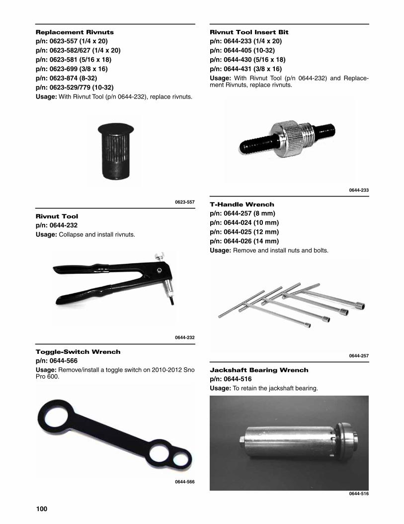
Replacement Rivnuts
p/n: 0623-557 (1/4 x 20)p/n: 0623-582/627 (1/4 x 20)p/n: 0623-581 (5/16 x 18)p/n: 0623-699 (3/8 x 16)p/n: 0623-874 (8-32)p/n: 0623-529/779 (10-32)Usage: With Rivnut Tool (p/n 0644-232), replace rivnuts.
0623-557
Rivnut Tool
p/n: 0644-232Usage: Collapse and install rivnuts.
0644-232
Toggle-Switch Wrench
p/n: 0644-566Usage: Remove/install a toggle switch on 2010-2012 SnoPro 600.
0644-566
Rivnut Tool Insert Bit
p/n: 0644-233 (1/4 x 20)p/n: 0644-405 (10-32)p/n: 0644-430 (5/16 x 18)p/n: 0644-431 (3/8 x 16)Usage: With Rivnut Tool (p/n 0644-232) and Replace-ment Rivnuts, replace rivnuts.
0644-233
T-Handle Wrench
p/n: 0644-257 (8 mm)p/n: 0644-024 (10 mm)p/n: 0644-025 (12 mm)p/n: 0644-026 (14 mm)Usage: Remove and install nuts and bolts.
0644-257
Jackshaft Bearing Wrench
p/n: 0644-516Usage: To retain the jackshaft bearing.
0644-516
100

T Wrench
p/n: 0644-021Usage: Drive 3/8 in. square-drive sockets.
0644-021
Torx Bit Insert (5/16 in. Hex Drive)
p/n: 0644-314Usage: With Insert Holder (p/n 0644-315), remove andinstall torx-head screws.
0644-314
Torx Bits (1/4 in. Hex Drive)
p/n: 0644-312 (#25)p/n: 0644-393 (#27)p/n: 0644-215 (#30)p/n: 0644-313 (#40)Usage: With Quick-Disconnect Coupler (p/n 0644-308),remove and install torx-head screws.
0644-312

NOTES
102

Declaration of Conformity
I, the undersigned, hereby declare that the equipment specified above conforms to the directive(s) and standard(s) as specified.
Brad DarlingVice President/General Manager - Snowmobile Division
Application of council directives:Issued by European Commission.
EMC Directive 2004/108/ECEC Machinery Directive 2006/42/EC
Type of Equipment: SnowmobileBrand Name: Arctic CatModel Numbers:
S2015ACDCCUSG
Standards to which conformity is declared:
EMC:MACHINERY:
EN 55012, EN 61000-6-2EN 12100:2010
Manufacturer (if not issuing agent): Arctic Cat Inc.601 Brooks Ave. S.Thief River Falls, MN56701 USA
103

Printed in U.S.A. Trademarks of Arctic Cat Inc. Thief River Falls, MN 56701 p/n 2260-495Phone: (218) 681-9851 - U.S. (204) 982-1656 - Canada
®TM


