Operator's manual 4-row potato planter UP3745
68
Operator's manual UP3745 EN, issue 2008 Operator's manual 4-row potato planter UP3745 UH124416
Transcript of Operator's manual 4-row potato planter UP3745

Operator's manual UP3745 EN, issue 2008
Operator's manual 4-row potato planter
UP3745UH124416

2
Operator´s manual Underhaug UP3745 potato planter

3
Operator´s manual Underhaug UP3745 potato planter
CE certificate of conformityWe, TKS Mekaniske AS, Torlandsvegen 3 N-4365 Nærbø Norway declare under our sole responsibility that the product: Potato planter type Underhaug UP3745 to which this declaration relates corresponds to the relevant basic safety and health requirements of the Directives 89/392/EEC, 91/368/EEC, 93/44/EEC and 93/68/EEC.
Nærbø, 15 September 2008
Henning Thunheim Managing Director
CE certificate of conformity
TKS Mekaniske AS, manufacturers of farm machinery reserve the right to change designs and/or specifications without notice. This does not include an obligation to make changes to machines previously supplied.
Enter here the serial number of your machine:

4
Operator´s manual Underhaug UP3745 potato planter
GuaranteeTKS products are guaranteed for a period of one year from the date of delivery, against defects in material and workmanship.Components not manufactured by TKS. electrics and hydraulics, PTO shafts and tyres are guaranteed according to the original manufacturer’s recommendation.The components listed below have limited guarantee due to their function:
Tyres Pre-stretcher rollers Belts Knives Lamps Fuses Oil filter Hydraulic seals of motors, valves and cylinders.
Weakening due to wear and tear is considered to be normal for these parts. The product guarantees for these components are limited to manufacturing defects, breakage, poor workmanship, transport damage etc on new machines.Any damage to bearings that are fitted with grease nipples is not covered under the standard product guarantee, if the damage is shown to be caused by rust or due to the ingress of liquids. Such damage is caused by insufficient lubrication or the use of low quality lubricants.Any damage caused by the use of corrosive additives in or nearby the machine is also not covered.If a failure is expected to be covered under the guarantee, the owner or its representative should inform the dealer when parts and/or repair work is required. Any guaranty claim should be applied for within the period of guarantee.The dealer should fill in one guarantee claim form for each matter and forward it to the TKS representative before the 10th of the following month after the claim was raised.The damaged parts should be marked with the number of the corresponding warranty claim and should be stored for 6 months by the dealer, available for inspection by the TKS representative if required.Due to the operation of the TKS products being out of the manufacturer’s control, the guarantee covers the product quality only. Performance or any consequential losses are not covered.
The guarantee may be invalid if: a) spurious spare parts are used or the product is repaired or modified without the TKS authorisation. b) operator’s and service instructions given by the manufacturer are not complied with. c) The machine is used for other purposes than those designed for.
The guarantee does not cover damage caused by normal wear.Public safety regulations require from the manufacturer of this machine that all safety aspects regarding the use of the machine is thoroughly evaluated. As a result of these obligations TKS and its representative are not responsible for the function of components not shown in the spare parts catalogue covering this product.TKS reserve the right to change the product with no obligation to previously supplied machines.
Guarantee

5
Operator´s manual Underhaug UP3745 potato planter Content
ContentCE certificate of conformity.................................. 3Guarantee............................................................ 4Introduction .......................................................... 6Machine identification .......................................... 7Technical specifications ....................................... 8Dimensions .......................................................... 9Model descriptions............................................. 12Safety .................................................................... 141 Preparing a new machine........................ 211.1 Packing.................................................... 211.2 Row width control .................................... 211.3 Assembling the coverers ......................... 221.4 Wheel axle............................................... 231.5 Drawbar ................................................... 241.6 Hopper..................................................... 241.7 Markers ................................................... 251.8 Fertilizer attachment ................................ 251.9 Potato planter .......................................... 261.10 Potato planter with fertilizer ..................... 261.11 Transporting wheel .................................. 271.12 Frame jack............................................... 272. TRACTOR REQUIREMENTS ................. 29
3. TRACTOR CONNECTIONS ................... 303.1 Road transport......................................... 303.2 Hydraulic drive system ............................ 324. OPERATING THE MACHINE .................. 364.1 Seed potato size...................................... 364.2 Depth control ........................................... 364.3 Covering up ............................................. 384.4 Working speed ........................................ 384.5 Belt agitation............................................ 394.6 Regulation of potato flow from hopper to planting units ....................................... 404.7 Emptying the potato hopper .................... 405 ELECTRONIC CONTROL PANEL .......... 425.1 The keys of the control panel .................. 425.2 Connecting the tractor power supply ....... 425.3 Panel display ........................................... 445.4 Alarms displayed on screen .................... 606 MAINTENANCE ...................................... 646.1 Maintenance of mechanic components ... 646.2 Maintenance hydraulics........................... 656.3 Maintenance electrics & electronics ........ 657. TROUBLE SHOOTING ........................... 66Notes ................................................................ 67

6
Operator´s manual Underhaug UP3745 potato planter
IntroductionWe congratulate you on the purchase of your new TKS product. You have chosen a product which will give you satisfaction through a network of efficient dealers where function, finish, after sales service and spare parts are always at hand.All TKS products are designed and tested in close co-operation with farmers and contractors to ensure optimal function and reliability.Please read this manual before using your new machine.We wish you all the best with your TKS product.
Yours faithfullyTKS Mekaniske AS
Introduction
TKS Mekaniske AS, Torlandsveien 3 N-4365 Nærbø Norway e-post : [email protected] +47 51 43 63 00 Fax +47 51 43 48 62

7
Operator´s manual Underhaug UP3745 potato planter
Machine identificationThe machine’s serial number and the manufacturer’s address are found on the number plate of the machine. See illustration below.The serial number and year of manufacture for this machine is given below. This number is important with regard to service and the correct supply of spare parts.The machine is marked CE. This marking with appurtenant EU statement of agreement means that the machine complies with substantial health and security demands, and that it is accordance with the directives 89/392/ECC as amended by directive 91/368/EEC, 93/44/EEC and 89/336/EEC.
Serial number
Machine identification
Serial number
8
Operator´s manual Underhaug UP3745 potato planter
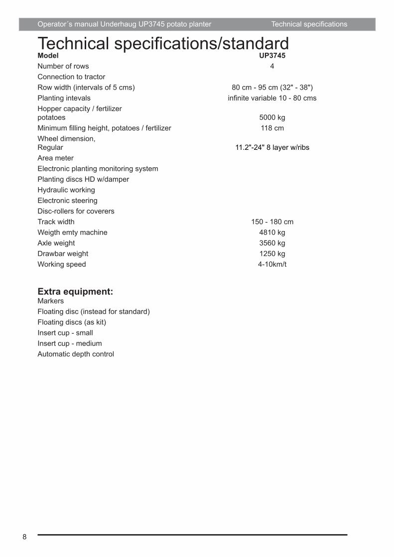
Technical specifications/standardModel UP3745Number of rows 4Connection to tractor Row width (intervals of 5 cms) 80 cm - 95 cm (32" - 38")Planting intevals infinite variable 10 - 80 cmsHopper capacity / fertilizer potatoes 5000 kgMinimum filling height, potatoes / fertilizer 118 cmWheel dimension, Regular 11.2"-24" 8 layer w/ribsArea meterElectronic planting monitoring systemPlanting discs HD w/damperHydraulic workingElectronic steeringDisc-rollers for coverersTrack width 150 - 180 cmWeigth emty machine 4810 kgAxle weight 3560 kgDrawbar weight 1250 kgWorking speed 4-10km/t
Extra equipment:MarkersFloating disc (instead for standard)Floating discs (as kit)Insert cup - smallInsert cup - mediumAutomatic depth control
Technical specifications

9
Operator´s manual Underhaug UP3745 potato planter
4960
6050
1870
3270
Dimensions
All dimensions are in mm (1" = 25.4mm)
DimensionsValid for machine with wheel size 11,2"-24" 8 PLY lugged left and right

10
Operator´s manual Underhaug UP3745 potato planter

11
Operator´s manual Underhaug UP3745 potato planter
601019
9032
007100
Dimensions potato planter w/fertilizerValid for machine with wheel size 11,2"-24 8 PLY lugged left and right
All dimensions are in mm (1" = 25.4mm)
Dimensions

12
Operator´s manual Underhaug UP3745 potato planter
Model descriptionsThe UP3745 automatic potato planter from TKS is a 6 row trailed machine. The planting units include double cup belts, adjustable gate between hopper and planting unit, adjustable row width, hydraulic drive powered by the hydraulic pump of the tractor, infinite planting distance adjustment, rigid furrow openers and manually or automaticcally controlled planting depth. The machine is available as follows:
6-row basic machine, row width 80cm 6-row basic machine, row width 32" 6-row basic machine, row width 85cm 6-row basic machine, row width 34" 6-row basic machine, row width 90cm 6-row basic machine, row width 36" 6-row basic machine, row width 95cm 6-row basic machine, row width 38"
The machine is equiped with hydraulic hopper 5000KgThe machine is equiped with double cup belt.
Choose between folowing cup types: - Planting cup Ø66mm - Planting cup Ø74mm - Planting cup
The planter is delivered with disc roller 450mm to coverer.
Model descriptions

13
Operator´s manual Underhaug UP3745 potato planter Model descriptions

14
Operator´s manual Underhaug UP3745 potato planter
SafetyBefore operating, adjusting or servicing the machine it is important that the safety instructions in this manual are carefully read and understood by those, which are directly concerned. (Fig. 1)Whilst all care and attention has been taken in the design and production of this machine, as with all machinery there remains a certain amount of risk to personnel whilst the machine is in use. It is strongly recommend-ed that users and operators take all possible precautions to ensure both their own safety and that of the others that may be in the vicinity.Read and observe the safety instructions in this manual. Safety is your responsibility!
Pay particular attention to this symbol. It means that there could be a
serious hazard. It emphasises precautions, which have to be complied with in order to prevent accidents.This symbol can be found throughout this manual and on the warning signs of the machine. They are for your safety and should be observed at all time.Be careful when other people or animals are close by! Never start the machine when people or animals are close by tractor or machine. Never stand between the tractor wheels and machine. (Fig. 2)Bear in mind regulations regarding the lower age of operators of this kind of machines.Use of the machine The machine should be used only for the purpose it has been designed for.Use personal protection devices Do not wear loose clothing, which might catch in any of the moving parts. In dusty conditions an approved mask must be used. (Fig. 3)Take care of excessive noise level. Some tractor/implement combinations, depending on conditions, may cause noise level beyond 85dB at the operator’s ears, even in a “Q” cab. In these conditions ear defenders must be worn. Keep cab windows and doors closed to reduce noise level.
The machine must be connected to a correctly sized tractor The weight of the tractor must correspond to the maximum weight of the machine when operated. Follow domestic law and regulations. (Fig. 4)Make sure that the tractor has the correct PTO gear engaged. A machine designed for an input speed of 540 rpm. should never be connected to a tractor with 1000 rpm. output speed engaged. The normal PTO speed is given on a label close to the PTO input shaft.Connecting machine to tractor must always be carried out as described in this manual. If connection should be carried out with drawbar, one of the parts (tractor or machine’s drawbar) must have a clevis. The drawbar pin must be secured with a lock pin. (Fig. 5)Observe national regulations regarding road transport. Some countries require the use of safety chain when a trailed machine is towed along public roads.Think of safety while operating the ma-chine Stop the tractor engine and remove the ignition key prior to carrying out repairs, cleaning, lubrication or maintaining the machine. (Fig. 6)Safety guards Make sure all guards are in good order and fitted correctly. Do not attempt to start the machine before ensuring this. (Fig. 7)Pay particular attention to the plastic guards of the PTO shaft. If damaged they must be replaced. The chain locks of the guards must always be fitted on a suitable place on the tractor and the machine to prevent the outer plastic guards turning.Hydraulics Be very careful when dealing with hydraulics. Use eye protection and gloves. Escaping hydraulic oil under pressure might penetrate into the skin and cause serious infection. See a doctor if you have been exposed to injury. (Fig. 8)Take care that nobody is close to the machine when the hydraulic functions are being operated.
Safety

15
Operator´s manual Underhaug UP3745 potato planter
Fig. 2Fig. 1
Fig. 3 Fig. 4
Fig. 6Fig. 5
Fig. 7 Fig. 8
Safety

16
Operator´s manual Underhaug UP3745 potato planter
When uncoupling machine and when leaving tractor/machine When uncoupling, all hydraulic functions must be in neutral position. The machine must be lowered to the ground and be safely secured. If the machine has parking chocks they should be used at the wheels. Never allow children to play or stay near agricultural machinery. (Fig. 9)Drive safely Beware of your responsibility, - carelessness or negligence may cause serious injury or even death. (Fig. 10)Prior to transporting the machine along public roads, check wheel bolts and couplings. Disconnect or lock the hydraulic system.Drive carefully. Reduce speed when turning and driving on uneven ground. Take care that trailed machine does not start swinging or become unstable.Please be aware of the danger of overturning when working on slopes and in soft ground. Reduce load.
Lights The owner and operator is responsible of providing correct lamps and reflectors on the machine when transported on public roads. Comply with public regulations. (Fig. 11)Safety equipment Always carry first aid equipment on the tractor. Also observe the regulations concerning fire extinguisher. When working with burning materials like hay and straw a fire extinguisher must be available at all times. (Fig. 12)Spare parts For safety reasons use only original spare parts. The use of spurious spare parts will cause the Underhaug product guarantee to be invalid. (Fig. 13)Maintenance Take care that the machine is properly maintained and kept in good safe working condition. Never change the basic technical construction of the machine.
Safety

17
Operator´s manual Underhaug UP3745 potato planter
Fig. 10Fig. 9
Fig. 11 Fig. 12
Fig. 13
Safety
18
Operator´s manual Underhaug UP3745 potato planter
Supplementary safety instructions for the UP3745 potato planterThis machine is designed for the purpose of baling & stretch film wrapping of grass or other straw material in the form of round bales.
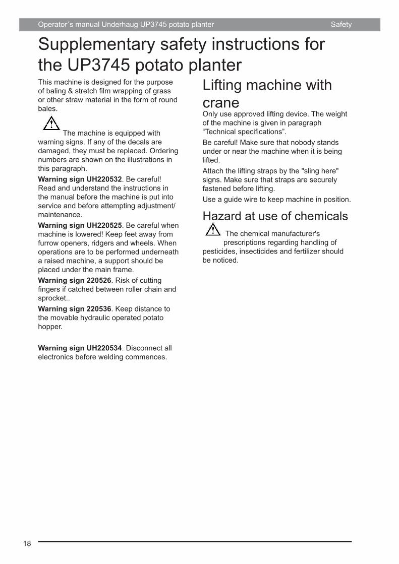
The machine is equipped with warning signs. If any of the decals are damaged, they must be replaced. Ordering numbers are shown on the illustrations in this paragraph.Warning sign UH220532. Be careful! Read and understand the instructions in the manual before the machine is put into service and before attempting adjustment/maintenance.Warning sign UH220525. Be careful when machine is lowered! Keep feet away from furrow openers, ridgers and wheels. When operations are to be performed underneath a raised machine, a support should be placed under the main frame.Warning sign 220526. Risk of cutting fingers if catched between roller chain and sprocket..Warning sign 220536. Keep distance to the movable hydraulic operated potato hopper.
Warning sign UH220534. Disconnect all electronics before welding commences.
Lifting machine with craneOnly use approved lifting device. The weight of the machine is given in paragraph “Technical specifications”.Be careful! Make sure that nobody stands under or near the machine when it is being lifted.Attach the lifting straps by the "sling here" signs. Make sure that straps are securely fastened before lifting. Use a guide wire to keep machine in position.
Hazard at use of chemicals The chemical manufacturer's prescriptions regarding handling of
pesticides, insecticides and fertilizer should be noticed.
Safety

19
Operator´s manual Underhaug UP3745 potato planter
UH220532 UH220525
UH220526 UH220536
UH220535 UH220522
Safety

20
Operator´s manual Underhaug UP3745 potato planter
New machine - be carefulRead the operator’s manual. Great care must be taken when starting a brand new machine for the first time. Incorrect assembly, faulty operations etc. may cause expensive repairs and loss of profit. The Underhaug product guarantee does not cover damage occurring when the instructions given in this book are not followed.
Pay particular attention to this symbol, - it emphasises operations where great
care must be taken in order to avoid incorrect assembly, faulty operations etc.Carefully do as described below when starting a new machine.Check that the machine is mounted correctly and that it is not damaged. Assure that electric wirings have length and position that allow machine to move without causing any damage to the wirings.Check the connections between tractor and machine.Check that the roller chains are tensionned and correctly positioned on the sprockets.Check that the drive rollers on top of both planting tubes are equally adjusted in order to assure cup belts run straight.Lubricate the machine according to lubrication instructions.Check wheel bolts torque setting.
CleaningGeneralWe recommend the use of pressured air when cleaning the machine. Thus there is less risk of damaging the bearings of the machine. If high pressure water is used, keep clear of bearings and electric components.
CylindersAssure that piston rods are kept free from aggressive chemicals in order to avoid corrosion.
Safety
21
Operator´s manual Underhaug UP3760 potato planter
Fig. 20
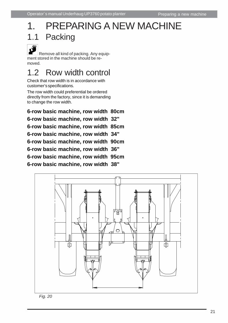
1. PREPARING A NEW MACHINE1.1 Packing
Remove all kind of packing. Any equip-ment stored in the machine should be re-moved.
1.2 Row width controlCheck that row width is in accordance withcustomer’s specifications.The row width could preferential be ordereddirectly from the factory, since it is demandingto change the row width.
Preparing a new machine
6-row basic machine, row width 80cm6-row basic machine, row width 32"6-row basic machine, row width 85cm6-row basic machine, row width 34"6-row basic machine, row width 90cm6-row basic machine, row width 36"6-row basic machine, row width 95cm6-row basic machine, row width 38"
22
Operator´s manual Underhaug UP3760 potato planter
Fig. 21
Fig. 22
C
D
B
A
E
EF
Preparing a new machine
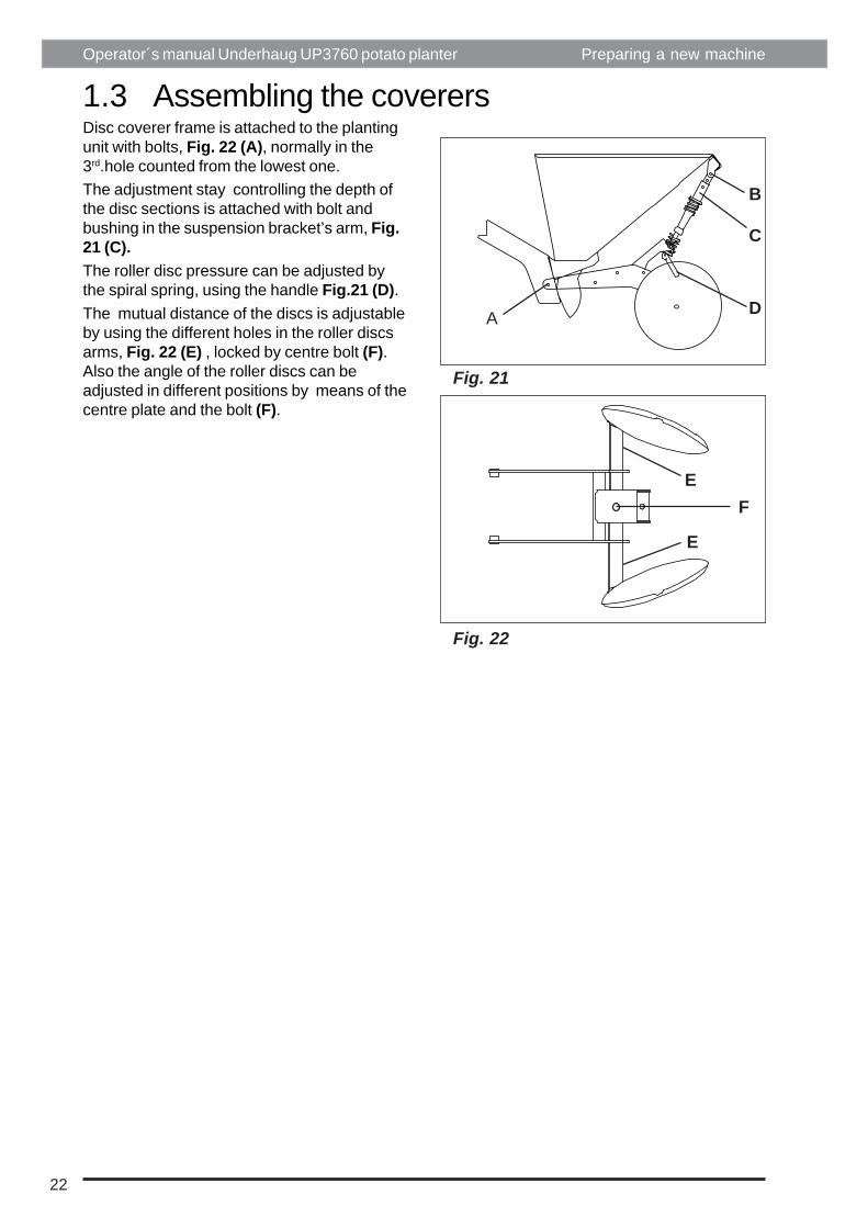
1.3 Assembling the coverersDisc coverer frame is attached to the plantingunit with bolts, Fig. 22 (A), normally in the3rd.hole counted from the lowest one.The adjustment stay controlling the depth ofthe disc sections is attached with bolt andbushing in the suspension bracket’s arm, Fig.21 (C).The roller disc pressure can be adjusted bythe spiral spring, using the handle Fig.21 (D).The mutual distance of the discs is adjustableby using the different holes in the roller discsarms, Fig. 22 (E) , locked by centre bolt (F).Also the angle of the roller discs can beadjusted in different positions by means of thecentre plate and the bolt (F).
23
Operator´s manual Underhaug UP3760 potato planter
Fig. 23
E
D
2RA
K
B
C
J
H
1.4 Wheel axlePreparing a new machine
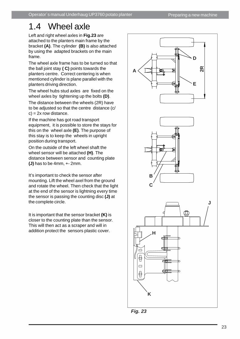
Left and right wheel axles in Fig.23 areattached to the planters main frame by thebracket (A). The cylinder (B) is also attachedby using the adapted brackets on the mainframe.The wheel axle frame has to be turned so thatthe ball joint stay ( C) points towards theplanters centre. Correct centering is whenmentioned cylinder is plane parallel with theplanters driving direction.The wheel hubs stud axles are fixed on thewheel axles by tightening up the bolts (D).The distance between the wheels (2R) haveto be adjusted so that the centre distance (c/c) = 2x row distance.If the machine has got road transportequipment, it is possible to store the stays forthis on the wheel axle (E). The purpose ofthis stay is to keep the wheels in uprightposition during transport.On the outside of the left wheel shaft thewheel sensor will be attached (H). Thedistance between sensor and counting plate(J) has to be 4mm, +- 2mm.
It’s important to check the sensor aftermounting. Lift the wheel axel from the groundand rotate the wheel. Then check that the lightat the end of the sensor is lightning every timethe sensor is passing the counting disc (J) atthe complete circle.
It is important that the sensor bracket (K) iscloser to the counting plate than the sensor.This will then act as a scraper and will inaddition protect the sensors plastic cover.

24
Operator´s manual Underhaug UP3760 potato planter
Fig. 24
Fig. 25
A
CB
1.6 HopperConnect the hopper Fig.25 to the planter atthe hinges (A) by using the 3 central hingebolts and one hinge bolt on each side .Assemble the 3 cylinder brackets (B) on themid plate of the hopper and connect the 3lifting cylinders (C) with bolts.
1.5 DrawbarAttach the drawbar to the planter with bolts (A)and (B). Adjust the drawbar eye (C) : Inworking position the drawbar should be asclose to horizontal position as possible.Support leg (D) will keep the drawbar inposition when planter is parked, thus making iteasy to connect the planter to the tractoragain.
Preparing a new machine
A
B
DC

25
Operator´s manual Underhaug UP3760 potato planter
Fig. 26
Fig. 27
1.8 Fertilizerattachment
Fertilizer attachment Fig.27The fertilizer attachment has to be fixed to theupper (A) and lower (B) frames.The frame is being reinforced by the 2diagonal stays (C), which have to be finetuned by the ball joints (D).Fix the roller discs (E) on the fertilizerattachments frame just in front of the plantingunitsGuide the fertilizer tubes (F) into position byusing the brackets (G).
1.7 MarkersLeft marker Fig. 26.Fit the left and right markers to the plantersframe with bolt (A) and (B) and the markerscylinder (C). Adjust the roller disc with thetelescopic arm (D) . The marker will indicatewhere the middle of the tractor is to run. Inworking position the distance from the middleof the planter to the marker should be 6 x therow width .
Preparing a new machine
AD
C
E
F
G
B
CB D
A
Dri
ving
dire
ctio
n
26
Operator´s manual Underhaug UP3760 potato planter Preparing a new machine
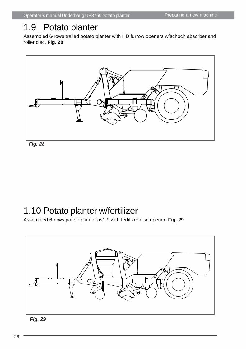
1.9 Potato planterAssembled 6-rows trailed potato planter with HD furrow openers w/schoch absorber androller disc. Fig. 28
1.10 Potato planter w/fertilizerAssembled 6-rows poteto planter as1.9 with fertilizer disc opener. Fig. 29
Fig. 28
Fig. 29

27
Operator´s manual Underhaug UP3760 potato planter
1.11 Transporting wheelPreparing a new machine
1.11 Transporting wheelWhen transporting the potato planter assemble transport wheel 3m (A), or if the planterhas fertilizer transporting wheel 3,5m (B). When changing from ordinary planting action toroad transport, moves outer part of the drawbar from position (C) to position (D). To getthe minimum width at road transport (under 3m without/fertilizer), must also the inner partof the drawbar be dismounted. Fig. 30
1.12 Frame jackFrame jack is a part of the equipment which follows the transporting wheel. Whenchanging the draw position, the frame jack has to be used to get the end of the planter inright position when connecting to tractor. Fig. 31
Fig. 30
Fig. 31
E
D
C
A
A

28
Operator´s manual Underhaug UP3760 potato planter

29
Operator´s manual Underhaug UP3760 potato planter Tractor requirements
2. TRACTOR REQUIREMENTSThe hydraulics recommended lifting capacity:
Planter size Recommended tractor sizeSix row without fertilizer min. 100 hk6-row with fertilizer min. 120 hk
Hydraulic connectionSingle acting output with free return, continuous oil flow, capacity 45 litres/min.One double acting hydraulic valve.
Electrical supply12V, standard 12mm.IMPORTANT! Ensure all electrical contacts and the socket are well connected in order toavoid a power supply cutoff due to vibrations. Even a very short cutoff will start thecomputer test procedure.
30
Operator´s manual Underhaug UP3760 potato planter Tractor connections
3. TRACTOR CONNECTIONS3.1 Road TransportPrepare the planter for road transport:-Lower the planter to parking position, andraise the hopper to top position. Securewheels and hopper with the attached yellowstays.-Disconnect and move hydraulic hoses, powercable, cable from control panel in cab, anddisconnect drawbar-Move the front part of drawbar from plantingposition to bracket for road transport on theleft side of planter, and secure.-Re-position tractor-Connect hydraulic hoses for transport wheels-Raise planter on transport wheels (by turninghandle on the flow direction valve) and framejack to a height where the drawbar can beconnected to the tractor.-If necessary remove inner part of the drawbarfor planting position to obtain narrowertransport width. By removing the 4 mainwheels transport width will be reduced byanother 30 cms (12").
From transport to planting positionFollow the above instructions in reversedorder
Adjust the telescopic drawbar to a give acomfortable distance between planter andtractor wheels for sharp turns
Important! Remember to raise theparking leg to transport position before movingthe planter.
31
Operator´s manual Underhaug UP3760 potato planter
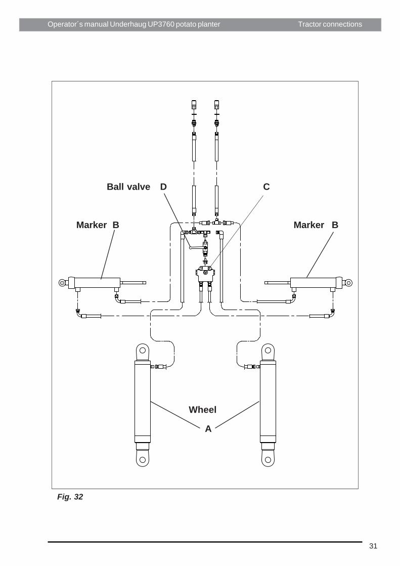
Fig. 32
MarkerMarker
Wheel
B B
A
CBall valve D
Tractor connections
32
Operator´s manual Underhaug UP3760 potato planter
3.2 Hydraulic drivesystem
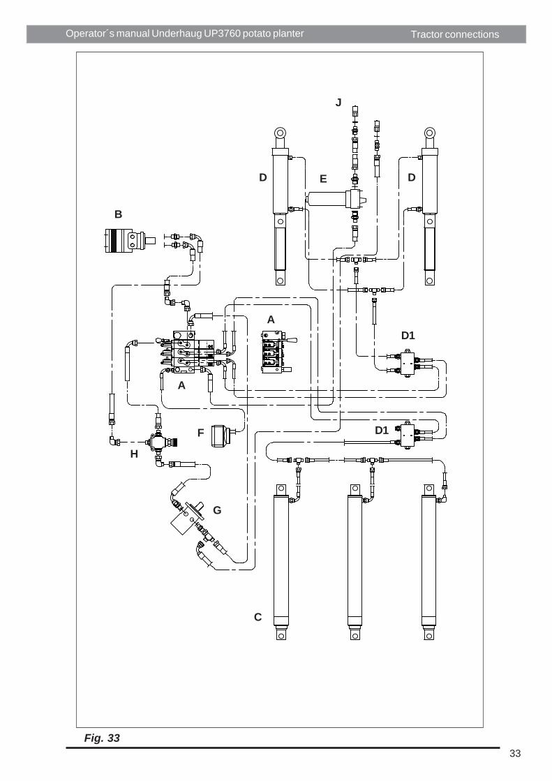
3.2.1 ComponentsThe hydraulic drive system on this machineconsists of the following items, Fig 33:- Two or four spools valve block (A)- Oil motor (B) for driving planting units- 3 cylinders (C) for lowering/raising of bunker- 2 cylinders (D) for lowering / raising ofdrawbar and 2 cylinders for lowerinig / raisingof main wheels- 2 pcs 2-way check valves (D1) for hoppercylinders- Oil filter (E)- Reservoir (F) for collecting oil leaking fromvalve- Oil motor (G) for driving the belt agitation- Flow control valve (H) for agitation frequency
OptionOil motor for driving fertiliser attachment
3.2.2 Connecting the hydraulic valveWhen connecting hydraulic hoses to tractor,the pressure hose goes to the oil filter on theplanter, the second hose is return.
3.2.3 Connecting tractor hydraulicsFig. 32The main wheels are connected directly to thetractor hydraulics for lowering /raising, andoperated by the tractor levers.If row marker arms are fitted, cylinders tooperate these are also connected to thiscircuit, and the sequence valve (C) willalternate the left and right arms every time thecircuit is activated.If you don't want to drive with active marker,the function can be stopped by closing the ballvalve.
Tractor connections
33
Operator´s manual Underhaug UP3760 potato planter
Fig. 33
D
D1
D1
C
G
H
F
A
B
D E
J
A
Tractor connections
34
Operator´s manual Underhaug UP3760 potato planter
T P
7
23+24
4+5
Fig. 34
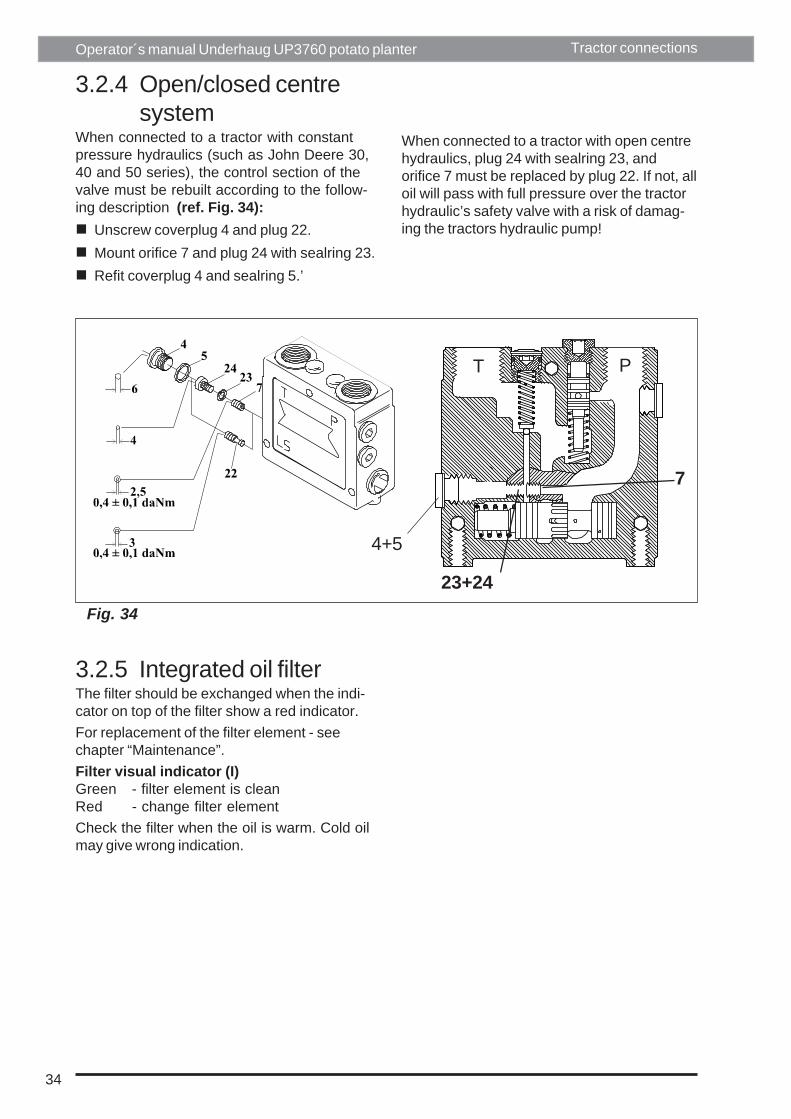
3.2.4 Open/closed centresystem
When connected to a tractor with constantpressure hydraulics (such as John Deere 30,40 and 50 series), the control section of thevalve must be rebuilt according to the follow-ing description (ref. Fig. 34):
Unscrew coverplug 4 and plug 22.Mount orifice 7 and plug 24 with sealring 23.Refit coverplug 4 and sealring 5.’
When connected to a tractor with open centrehydraulics, plug 24 with sealring 23, andorifice 7 must be replaced by plug 22. If not, alloil will pass with full pressure over the tractorhydraulic’s safety valve with a risk of damag-ing the tractors hydraulic pump!
3.2.5 Integrated oil filterThe filter should be exchanged when the indi-cator on top of the filter show a red indicator.For replacement of the filter element - seechapter “Maintenance”.Filter visual indicator (I)Green - filter element is cleanRed - change filter elementCheck the filter when the oil is warm. Cold oilmay give wrong indication.
Tractor connections

35
Operator´s manual Underhaug UP3760 potato planter
Fig. 35
3.2.6 Draining the valve bankThe valve bank is connected to a contain-er (fig. 27/F) positioned behind the left-hand rear side panel. If the return pres-sure of the oil from the valve bank is toohigh, e.g. the return hose is disconnectedwhile still pressure in pressure side, asmall volume of oil will flow into the con-tainer.The container should be emptied in anenvironmental friendly way.
3.2.7 Manual hydraulic operationThe valve bank can be manually operatedby using the lever included with the ma-chine. Connect the lever to the hexagonalshaft of the valve sections, see fig. 29.The lever is stored inside the panel cover-ing the valve bank.
Tractor connections

36
Operator´s manual Underhaug UP3760 potato planter
Fig. 40
B
A
4. OPERATING THE MACHINE4.1 Seed potato sizeUse graded seed potatoes as equal size gives an improved yield and optimal planter perform-ance.Recommended grading (square sieve):
Min. Max. Max length sieve sieve of potatoes
Large cup ø74mm .......................... 40mm ..................... 60mm..................... 100mmLarge inserts (white) ...................... 35mm ..................... 50mm...................... 75mmSmall inserts (green) ...................... 25mm ..................... 40mm...................... 55mm
The best result is achieved when the difference in the size is kept to a minimum.
4.2 Depth ControlPlanting depth is decided by adjusting thedrawbar cylinder (A) to required length.This can be done mechanically by lockingthe adjusting nut (B) on the cylinder in acertain position Fig.40. This procedure willgive the same planting depth every timethe machine is lowered on the drawbarcylinder.
When driving the machine with depthcontrol, the nut (B) have to be placed inupper position to prevent up and downmovement on the machine.
Operating the machine

37
Operator´s manual Underhaug UP3760 potato planter
Fig. 43
Fig. 42
Fig. 41
A
B
A
C
Operating the machine
a. Fixed opening shoe (fig. 40)Raise the machine and turn the adjustingnut (Fig. 40/B) to required setting. Thedepth will change with 12mm/14mm perturn (without or with fertiliser attachment).Lock the nut with the chain.
b. Floating opening shoe (Fig. 42)Adjust the length of the suspension chain(Fig. 42/A) so that the parallelogram ishorizontal when the planter is in plantingposition. Adjust to required depth (Fig.42/B) by the nut on drawbar cylinder asunder point a.Re-set the spring tension to compensatefor soil resistance so that an even plantingdepth is achieved even if the main wheelsshould sink in.
c. Floating planting shoes with depthwheels (Fig. 43)As point b. above, but after the depthwheel has been set at the requiredposition with the set screw (Fig. 43C), thesuspension chain may be lengthened witha few links.

38
Operator´s manual Underhaug UP3760 potato planter
Fig. 44
B
A
Operating the machine
4.3 Covering upa. Roller discs (Fig. 44):A large ridge is achieved by adjusting discs tomax. distance. Discs that are set to a wideangle will make sharp-topped ridges, whereasa smaller angle will produce flat ridges. Loos-en bolt (A) on the frame plate for adjustment.If the discs make the ridge too small due tohard or heavy soil, increase the spring pres-sure by lengthening the stay (B).
4.4 Working speed
Depends on cup belt speed, i.e. thechosen spacing.Small spacings = low speedLarge spacings = high speedSpacings (cm) x 0.25 = optimal working speed(km/h).Observe! Round seed can be planted at largerspeed while oblong and cut seed should beset at lower speed.

39
Operator´s manual Underhaug UP3760 potato planter
Fig. 45a
Fig. 45b
A
A
+-
Fig. 45c
B
Operating the machine
4.5 Belt agitationSet to minimise misses and doubles. Sixpositions (Fig. 45a/A).Minimum agitation = Large potatoes, high beltspeedMaximum agitation = Small potatoes, lowbelt speed
4.5.2 Electric agitationThe agotatpr motors are located inside theplanting units as shown in Fig. 45c. Thecontrol unit fitted on the main frame at thefront of the planter includes fuses for everymotor.It is important to make sure that every movablecomponent of the agitating system may movefreely, otherwise the motors may overload theelectric circuits causing fuses to blow.Adjust the agitator speed by means of thecontrol panel (see paragraph 6.8). Theagitator system's pressure on the cup belts isadjustable. Turn the handle (Fig. 45b/A)inwards or outwards. The agitation is in-creased when the handle A is turned anti-clockwise.In order to get access to the greas nipple (Fig.45c/B) the cup belt has to be disconnected.
4.5.1 Mechanic agitation9 positions (Fig. 45b/A)
40
Operator´s manual Underhaug UP3760 potato planter
Fig. 46
Fig. 47
A
BA
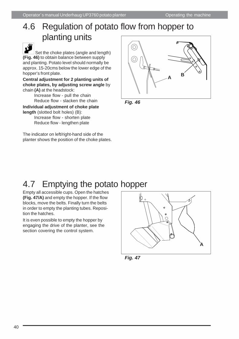
4.6 Regulation of potato flow from hopper toplanting units
Set the choke plates (angle and length)(Fig. 46) to obtain balance between supplyand planting. Potato level should normally beapprox. 15-20cms below the lower edge of thehopper’s front plate.Central adjustment for 2 planting units ofchoke plates, by adjusting screw angle bychain (A) at the headstock:
Increase flow - pull the chainReduce flow - slacken the chain
Individual adjustment of choke platelength (slotted bolt holes) (B):
Increase flow - shorten plateReduce flow - lengthen plate
The indicator on left/right-hand side of theplanter shows the position of the choke plates.
4.7 Emptying the potato hopperEmpty all accessible cups. Open the hatches(Fig. 47/A) and empty the hopper. If the flowblocks, move the belts. Finally turn the beltsin order to empty the planting tubes. Reposi-tion the hatches.It is even possible to empty the hopper byengaging the drive of the planter, see thesection covering the control system.
Operating the machine

41
Operator´s manual Underhaug UP3760 potato planter

42
Operator´s manual Underhaug UP3760 potato planter Electronic control panel
5 ELECTRONIC CONTROL PANELThe electronic control system includes (Fig. 50):
A Control panelB Black boxC Wheel sensorD Drive shaft sensorE Valve bank cableF Depth control sensor (optional)G Battery cableH Power supply cableI Panel cable
The black box is fitted behind the right-hand side panel of the planter.
5.1 The keys of the control panelSee Fig. 51.
A-B Arrow keys for moving the marker on the screenC Not in useD-E ± keys for change of screen valuesF Not in useG OK key confirming the selection/storing the new valueJ-O Function keys with variable function, see soft key display on screenWhen operating the ± keys (D-E) with no parameter selected, the screen contrast isadjusted.
5.2 Connecting the tractor power supplyIn order to start using a machine with electron-ic control system, the power supply to theblack box must be connected. Insert the plugin the power supply socket of the tractor. If thetractor does not include a proper power supplysocket, a new one should be fitted. A batterycable with fuse is included with the machine.Connect cable to the tractor's battery whenfitting the battery cable.Note that red cable should be connectedto the + terminal of the battery.
On the rear side of the panel an ON/OFFswitch is provided (Fig. 51/T). When turn ONthe control system is powered and the screenlights up.Wait then about 25 seconds for the mainmenu.
See Fig. 51 for the description of the keys ofthe control panel. See Fig. 51 regardingdescription of symbols on the screen and thevarying function of the function keys.
Disconnect the power supply if the ma-chine is not used for several days.
OBSERVE! The screen displays may differ slightly fromthe figures included in this manual.

43
Operator´s manual Underhaug UP3760 potato planter
Fig. 50
Fig. 51
B
A
DC
E
I
H
G
A1
Electronic control panel
J
Contrast
L K A D
G
B
E
F
C
NOM
Sound
T

44
Operator´s manual Underhaug UP3760 potato planter Electronic control panel
5.3 Panel displayOperating the machine:
A Start/stop of the machine
Note that forward speed should exceed 0,5 km/h to activate planter drive.Lower the machine and push the "START" key, see Fig. 52 (A). The keysymbol will thus change to show "STOP". Press "STOP" key to stop theplanter drive and continue for at least 2 meters in order to cover the end ofthe row. Thereafter raise the machine. During the planting the planting unitswill empty. To keep the correct level of tubers in the planting units, the hoppershould be raised. Use the "Raise hopper"/"Lower hopper" keys, see Fig.52 (C/D).Machines with automatic filling of the planting units, this will happenautomatically.It is recommended to maintain a fairly constant level of tubers in the plantingunits in order to obtain a good result.
B Changing between menues for operating the hydraulic functions on themachine
C Raise hopperD Lower hopperE Machine up/reduce planting depthF Machine down/increase planting depthG Increase agitation of cup beltH Decrease agitation of cup belt

45
Operator´s manual Underhaug UP3760 potato planter
Fig. 52
Electronic control panel
A
B
C
DE
FB
G
HB

46
Operator´s manual Underhaug UP3760 potato planter Electronic control panel
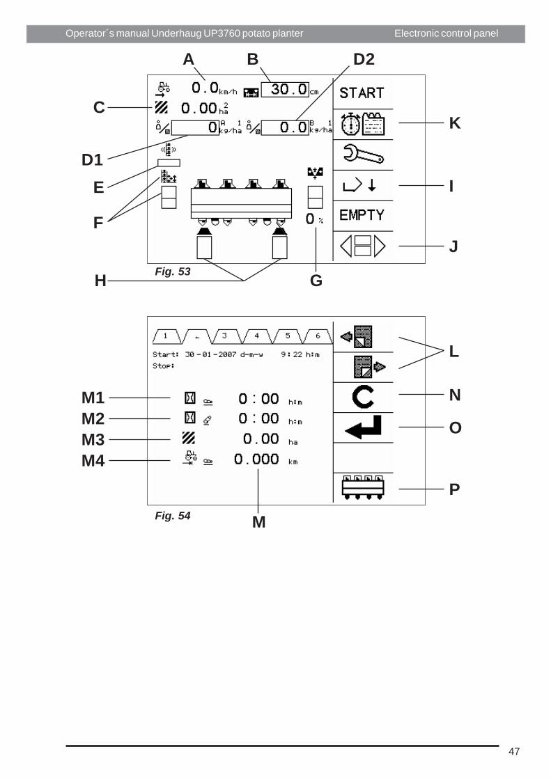
Main menu:A Showing the progress of speedB Wanted planting widthC Indicates the area registration which is active, and total areal in ha which
have been driven on this area registrationD1 Wanted fertilizer amount Kg/ha for fertilizer hopper AD2 (Wanted fertilizer amount Kg/ha for fertilizer hopper (B/C)E Indicates the agitation intensity Min-Max on the cup beltF Shows if the automatic hopper levelling sensor is activated and also the
potato level in the planting unitG Shows if the automatic depth control sensor is activated and also the
depth of the machineH Shows if the planting sensor is activated 2-8 rows and also the error
planting for each row (0-100%).I Lower hopper for loadingJ Empty planter with cup beltM1 Total time the machine has been driven in raised positionM2 Total time the machine has been driven in lowered positionM3 Total area with planted potatoesM4 Average speed during work
Area registration:K Change to area registrationL Change between area registration 1-20M Indicate for every area registrationN Reset the registrationsO Activates the choosen area registrationP Change to the main menu without activating choosen area registration
47
Operator´s manual Underhaug UP3760 potato planter
Fig. 53
Fig. 54
K
J
I
GH
F
ED1
C
A B D2
L
N
O
P
M
Electronic control panel
M1M2M3M4

48
Operator´s manual Underhaug UP3760 potato planter Electronic control panel
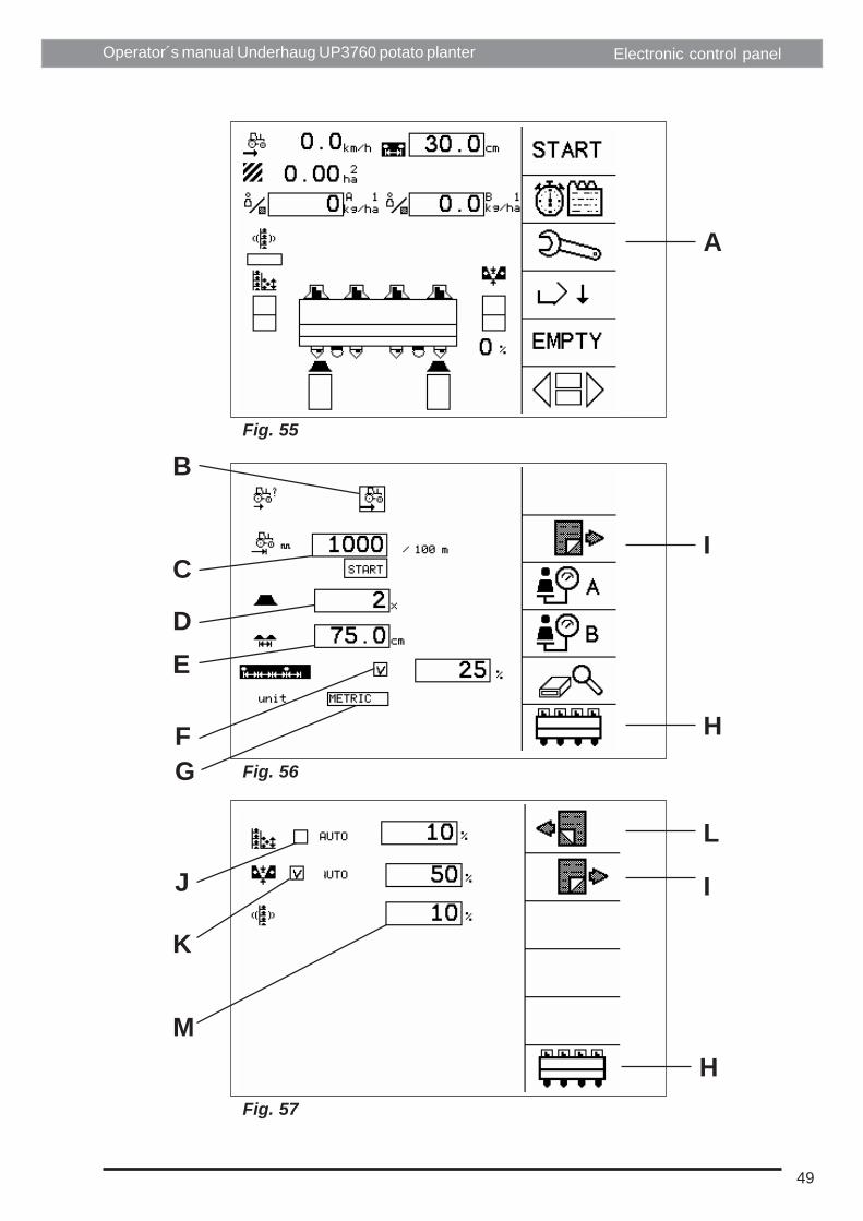
Programming/calibrating the machineProgramming the control:
A Service menuesB Activate the wheelsensor. If this is set to symbol "tractor"the wheel sensor
is activated and the wheel on the planter has to rotate for starting themachine. If this is set to symbol"hand" the sensor is not activated. And theplanter is starting directly after the start has been pressed. You then haveto add the speed of the tractor manually in the main menu. (Fig. 53 A)
C Calibration of the wheel diameter. Measure 100 meter (109 yd)Press the arrow key (Fig 51 A-B) until the "START" symbol is flashing.Press "OK" key and drive 100m (109 yd)Press once again "OK" key to store the correct numbers of pulses for100 meters (109 yd)
D Number of planting units. After confirming "OK" the current must beturned off/on, so the value in the software should be changed.
E Actual row withF Turn off/on the planting controlG Choose between metric and imperial measuring value. After confirming
"OK" the current must be turned off/on, so the value in the softwareshould be changed.
H Go directly to the main menuI Next pageJ Activates the hopper level sensor and add the wanted level of potato in
the planting unit from 0-100%, 0% gives a low level of potatoes, and100% gives high level of potatoes.
K Activate the depth sensor. Adjust the planting depth by setting the valuefrom 0-100%. 0% gives a shallow or none planting depth, and 100% givesmaximum planting depth
M Define the intensity fo the agitation for each press on++or-- (Se Fig. 57 G-H)
L Prevous pageI Next page
49
Operator´s manual Underhaug UP3760 potato planter Electronic control panel
A
I
H
L
I
H
GF
E
C
D
B
J
K
M
Fig. 55
Fig. 56
Fig. 57

50
Operator´s manual Underhaug UP3760 potato planter Electronic control panel
N Activate/deactivate the fertillizer hopper AO Activate/deactivate the granule hopper B or CL Prevous pageH Main menuI Dealer menu
Dealer menuThe different equipment on the machine:
A Activate the automatic hopper level sensorB Activate the automatic depth controlC Activate the electric agitation of the planting beltD Choose between trailed or mounted machineE Choose if the machine has an electric box for the fertilizer equipmentF Choose between machine trailed behind or offset (not for this model)G Choose the different fertilizer hoppers for the machineL Prevous pageH Main menuI Next pageJ Activate the hydraulic wheel steering (not for this model)I Activate the automatic wheel steering (not for this model)

51
Operator´s manual Underhaug UP3760 potato planter
Fig. 58
Fig. 59
Fig. 60
Electronic control panel
H
LI
H
A
LI
NO
L
I
D
BC
FE G
H
JK

52
Operator´s manual Underhaug UP3760 potato planter
Programming of the machines sensors and hydraulic valve:A This value is centering the proportional valve for the drive of the planting
belt. The value for the centre position of the valve is about 500 ppg. If thebelt is starting to late this value has to increase. Or if the belt is going tofast during planting this value has to reduce
B This value is centering the proportional valve for the drive of the plantingbelt. The value for the centre position of the valve is about 50%. If thefertilizer chain is starting to late this value has to increase. Or if the chainis going to fast during planting the value has to reduce.
C The active time for the hopper filling sensorTon = time cylinder is activeToff = time for next reacting
D The active time for the depth sensorTon = time cylinder is activeToff = time for next reacting
E After enter the "STOP" the machines runs (X) meters before lifting infront. And then (X) seconds before lifting up the rear of the machine, afterthe front lifting has started.
F (x) seconds the lifting in front is activatedG (x) seconds the lifting of the rear of the machine is activatedL Prevous pageH Main menu
Electronic control panel

53
Operator´s manual Underhaug UP3760 potato planter
Fig. 61
AL
D
BC
GFE
H
Electronic control panel

54
Operator´s manual Underhaug UP3760 potato planter
Calibrating the fertilizer equipment:A Service menuB Calibrating the fertilizer hopper (A)C Calibrating the granule hopper (B) or (C)D Wanted amount of fertilizer (Kg/ha)E Tractor speed (Km/t)F Wanted calibration area (ha).
This value controls the time of the calibration. If this value is too high,there will be a high amount of fertilizer coming out of the chain during thecalibration
G Next step in the calibration
Electronic control panel

55
Operator´s manual Underhaug UP3760 potato planter
Fig. 65
Fig. 66
Fig. 67
D
E
A
B
C
G F
Electronic control panel

56
Operator´s manual Underhaug UP3760 potato planter
How to do the calibrating:It's important that the calibrating is done on only one outlet. The programme is madeso it's automatically calculating the outputted fertilizer value in the program. So it's important toadd only small amount of fertilizer inthe tank where the current outlet is.Then hang a bucket or similar under the outlet to collect the fertilizer for weighing.
A Filling the fertilizer chain so it's ready for calibratingB Starting the calibratingC Pauses the calibrating
Electronic control panel

57
Operator´s manual Underhaug UP3760 potato planter
Fig. 68
Fig. 69
Fig. 70
A
B
C
Electronic control panel

58
Operator´s manual Underhaug UP3760 potato planter
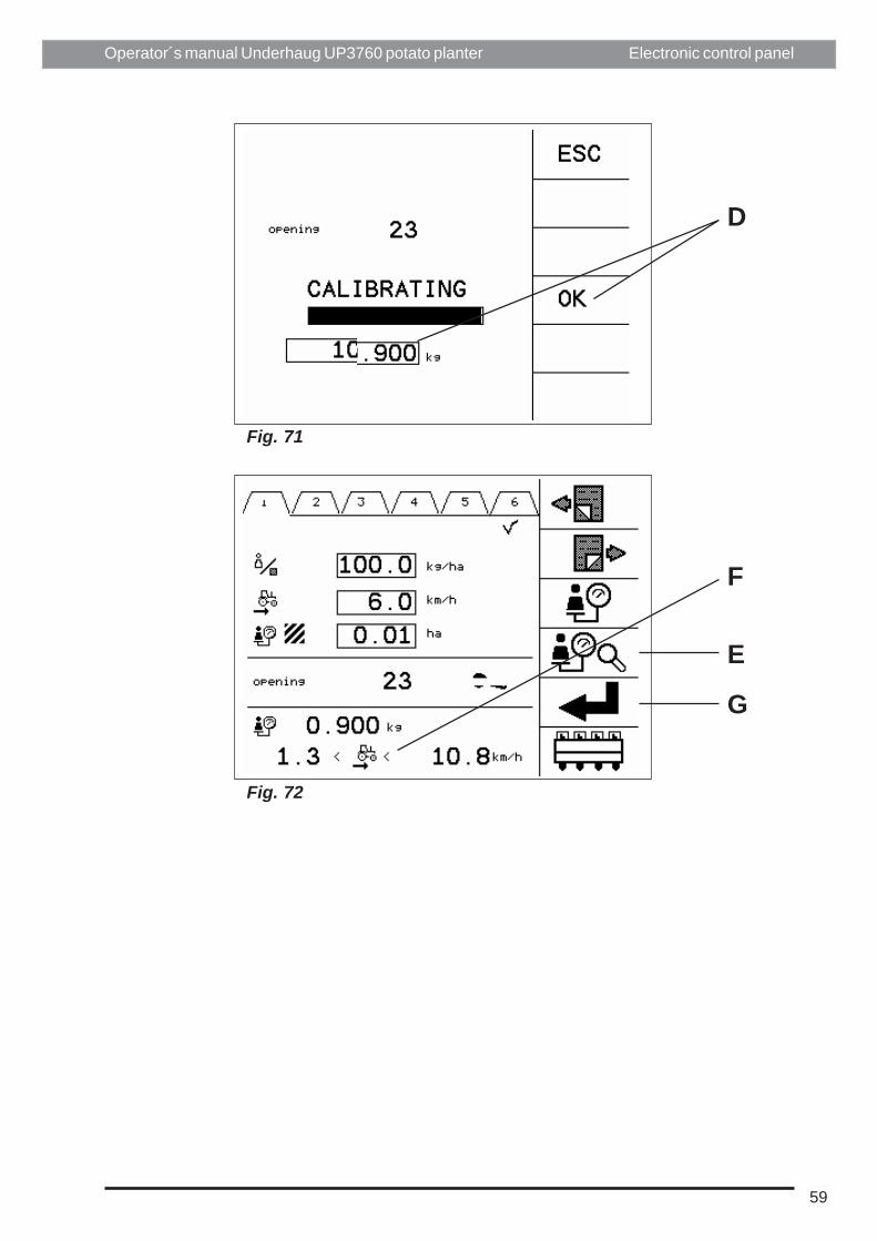
D After weighing output of fertilizer calibration test, enter number of Kg andconfirm with "OK"
E Testing of calibration.F Info about the minimum and maximum speedG Use this calibration for this area registration
Electronic control panel
59
Operator´s manual Underhaug UP3760 potato planter
Fig. 71
Fig. 72
D
E
G
F
Electronic control panel

60
Operator´s manual Underhaug UP3760 potato planter Electronic control panel
5.4 Alarms displayed on screen
5.4.2 Cup belts does not run
5.4.1. Misses (empty cups)See Fig. 75. Too many empty cups on rowunit number given in the alarm display.
Check the tuber level and the adjustments ofthe choke plates, agitators etc.
See Fig. 76. No oil supply to the drive motor.Check the hydraulic system.
5.4.3 Too low voltageSee Fig. 77. Check the electric connections ofcontrol system and the power supply systemof the tractor.

61
Operator´s manual Underhaug UP3760 potato planter
Fig. 75
Fig. 76
Fig. 77
Electronic control panel

62
Operator´s manual Underhaug UP3760 potato planter Electronic control panel
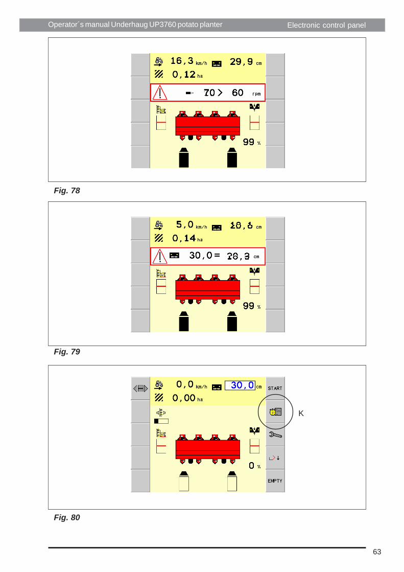
5.4.4 Too high speed of the cup beltsSee Fig. 78. Faulty planting distancesetting or too high forward speed on thetractor.
5.4.5 Varying planting distanceSee Fig. 79. Faulty oil supply to the planter.
5.4.6 Field registrationSee Fig. 80. Push key K (Field registra-tion) in order to activate the field registra-tion display.
63
Operator´s manual Underhaug UP3760 potato planter
Fig. 78
Fig. 79
Fig. 80
K
Electronic control panel
64
Operator´s manual Underhaug UP3760 potato planter
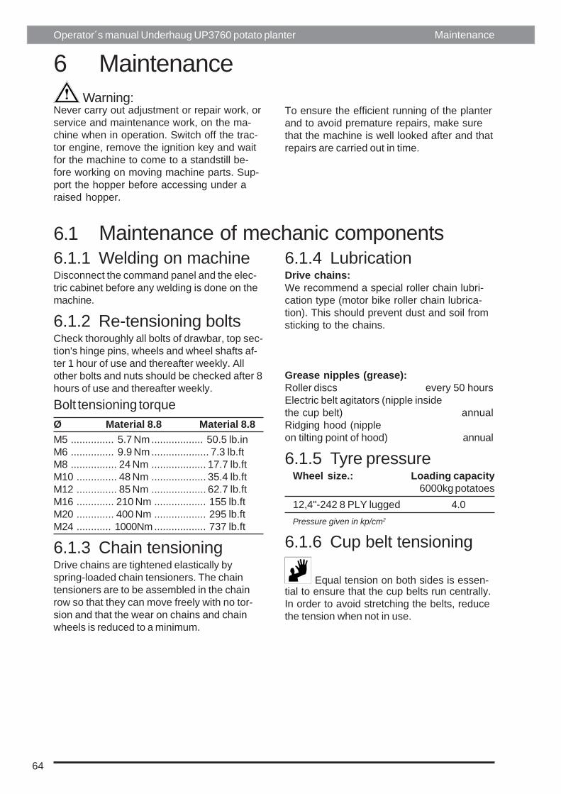
Warning:Never carry out adjustment or repair work, orservice and maintenance work, on the ma-chine when in operation. Switch off the trac-tor engine, remove the ignition key and waitfor the machine to come to a standstill be-fore working on moving machine parts. Sup-port the hopper before accessing under araised hopper.
Maintenance
6 Maintenance
To ensure the efficient running of the planterand to avoid premature repairs, make surethat the machine is well looked after and thatrepairs are carried out in time.
6.1 Maintenance of mechanic components6.1.1 Welding on machineDisconnect the command panel and the elec-tric cabinet before any welding is done on themachine.
6.1.2 Re-tensioning boltsCheck thoroughly all bolts of drawbar, top sec-tion's hinge pins, wheels and wheel shafts af-ter 1 hour of use and thereafter weekly. Allother bolts and nuts should be checked after 8hours of use and thereafter weekly.
Bolt tensioning torqueØ Material 8.8 Material 8.8M5 ............... 5.7 Nm .................. 50.5 lb.inM6 ............... 9.9 Nm .................... 7.3 lb.ftM8 ................ 24 Nm ................... 17.7 lb.ftM10 .............. 48 Nm ................... 35.4 lb.ftM12 .............. 85 Nm ................... 62.7 lb.ftM16 ............. 210 Nm .................. 155 lb.ftM20 ............. 400 Nm .................. 295 lb.ftM24 ............ 1000Nm .................. 737 lb.ft
6.1.3 Chain tensioningDrive chains are tightened elastically byspring-loaded chain tensioners. The chaintensioners are to be assembled in the chainrow so that they can move freely with no tor-sion and that the wear on chains and chainwheels is reduced to a minimum.
6.1.4 LubricationDrive chains:We recommend a special roller chain lubri-cation type (motor bike roller chain lubrica-tion). This should prevent dust and soil fromsticking to the chains.
Grease nipples (grease):Roller discs every 50 hoursElectric belt agitators (nipple insidethe cup belt) annualRidging hood (nippleon tilting point of hood) annual
6.1.5 Tyre pressureWheel size.: Loading capacity
6000kg potatoes12,4"-242 8 PLY lugged 4.0Pressure given in kp/cm2
6.1.6 Cup belt tensioning
Equal tension on both sides is essen-tial to ensure that the cup belts run centrally.In order to avoid stretching the belts, reducethe tension when not in use.

65
Operator´s manual Underhaug UP3760 potato planter
6.1.7 CleaningGeneralWe recommend the use of pressured airwhen cleaning the machine. Thus there isless risk of damaging the bearings of the ma-chine.CylindersKeep away from aggressive chemicals etc. inorder to avoid damage to the piston surface.
Maintenance
6.1.8 ControlCheck tightness of all bolts and nuts, especial-ly the wheel bolts, main frame bolts, bolts inhopper and any other main structure connec-tions highly stressed, after first day of workand at regular intervals thereafter.Check wearing points of furrow openers,ridging bodies and tines for excessive wear.Check wheel pressure.
6.2 Maintenance hydraulics6.2.1 Oil filterFilter visual indicator (I)Green - filter is cleanRed - change filter elementCheck the filter when the oil is warm (at tractor engine rpm. as for ordinary planting). Cold oil maygive wrong indication.Note! On tractors with closed centre system the motor must rotate in order to get correct indica-tion (oil must flow through the filter). Be careful. Beware of the rotating components.Filter exchange intervalsCheck the filter element every 20 hectar or at least once a season. The filter element should bereplaced for every 100 hectars being wrapped and always once a season.
Caution!Release pressure in the system before opening the filter housing.
6.2.2 Hydraulic tractor oil replacementKeep hydraulic oil clean! Clean hydraulic oil will prevent excessive wear and premature failure ofcomponents. Replace the tractor filter and oil as per manufacturer’s instructions.
6.3 Maintenance electrics & electronics6.3.1 ControlsCheck wirings for damage or corrosion.Check all plugs and sockets.
6.3.2 CleaningKeep command panel and electric cabinetclean. Use a moist cloth. Avoid flowing wa-ter.

66
Operator´s manual Underhaug UP3760 potato planter
7. Trouble shootingSymptom ActionInaccurate planting:Misses Remove/exchange inserts
Reduce belt agitationReduce working speedIncrease choke plates openings
Doubles Use cup insertsIncrease belt agitationIncrease working speedReduce choke plate openings
Doubles and misses Reduce variations of seed sizePotatoes out of line in the row Increase the planting depth to make a deeper
vee shaped furrowPotatoes out of centre of ridge Adjust coverers’ position according to
planter’s row centresFaulty planting depth a) Rigid furrow opener
Lift or lower land wheelsVarying planting depth a) Rigid furrow openers
Reduce hopper fillingCovering:Too little soil covering Increase depth of coverersToo much soil covering Reduce depth of coverersSharp top of ridge a) Disc coverers
Increase distance between pair of discsb) Ridging shovel/ridging hoodMove shovel wings inwards
Wide furrow a) Roller discsIncrease distance within the pari of discs
Narrow furrow a) Roller discs:Decrease distance within the pari of discs
Trouble shooting

67
Operator´s manual Underhaug UP3760 potato planter
NotesNotes

UH124404