Operator‘s manualmanual.poettinger.at/download/kotrdoku//0400-0499/0475_MEX 5 mit... · GB...
69
Operator‘s manual GB "Translation of the original Operating Manual" Nr. 99 475.GB.80P.0 MEX 5 (Type 475 : + . . 01001) Forage harvester
Transcript of Operator‘s manualmanual.poettinger.at/download/kotrdoku//0400-0499/0475_MEX 5 mit... · GB...

Operator‘s manualGB
"Translation of the original Operating Manual" Nr. 99 475.GB.80P.0
MEX 5(Type 475 : + . . 01001)
Forage harvester
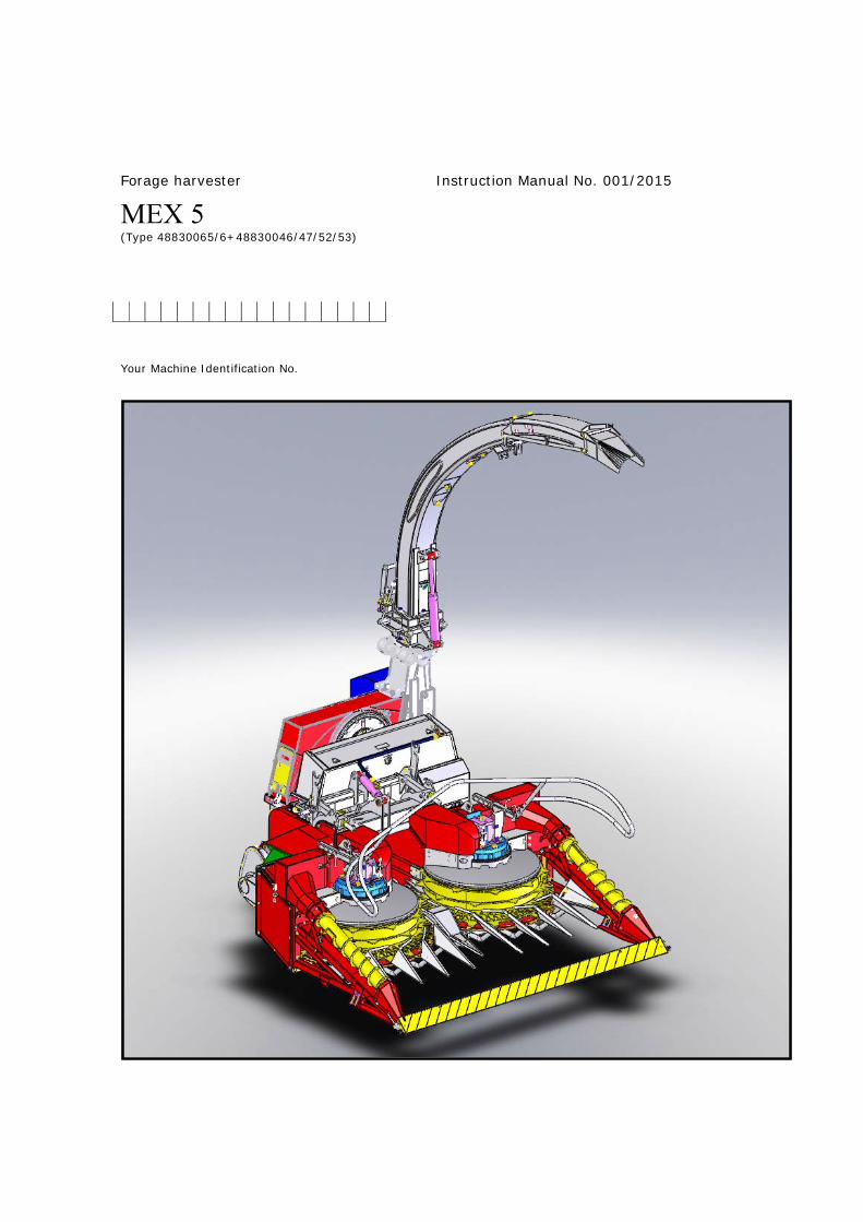
Forage harvester
MEX 5 (Type 48830065/6+48830046/47/52/53)
Instruction Manual No. 001/2015
Your Machine Identification No.
2
Index page Meaning of the warning signs
Putting into use
Putting into Use (general safety tips)
Opening of the blades disc lid
Travelling on public routes
Before starting work
Checks before use
Definition of the use of the machine
Correct charging
Location of the machine identification and its composition
The most important components of the machine
Technical information
First connection to the tractor
Hydraulic connection
Regulation of the hydraulic block
Connection of the hydraulic hoses/power source
Initial connection to the tractor (command functions)
Coupling the machine to the tractor
Lateral adjustment of the machine in relation to the tractor
Changing position of the transmission box
Metal detector (option)
Regulation/tuning
Tuning of the work speed
Adjusting the length of the cut
Alteration of speed of the feed rollers
Assembly or removal of the blades
Transport by road/safety devices
Transport by road
How to fold with a pipe
Fitting the safety devices
Operating in a field
Working recommendations
Regulation of the upper flap movement
Removing the safety devices
Regulation of the corn head to operate with 4 lines
Pipe blockage
How to switch off the machine
Cleaning
Assembly of the corn head
Assembly of the grass pickup
Adjusting and tuning the corn head
4
--
5
5/6
6
7
7/8
9
9
10
11/12
13
--
14
14
15/16
16
17
18/19
20
21/22
--
23
23/24
24
24/25
--
26
26/27
28/29
--
30
30
31
32/33/35
35
36
36
37/38
39/40
41
3
Maintenance and repairs
Maintenance and Repairs
Sharpening the blades
Adjusting the sharpening disc to the blades and vice-versa
Sharpening procedure
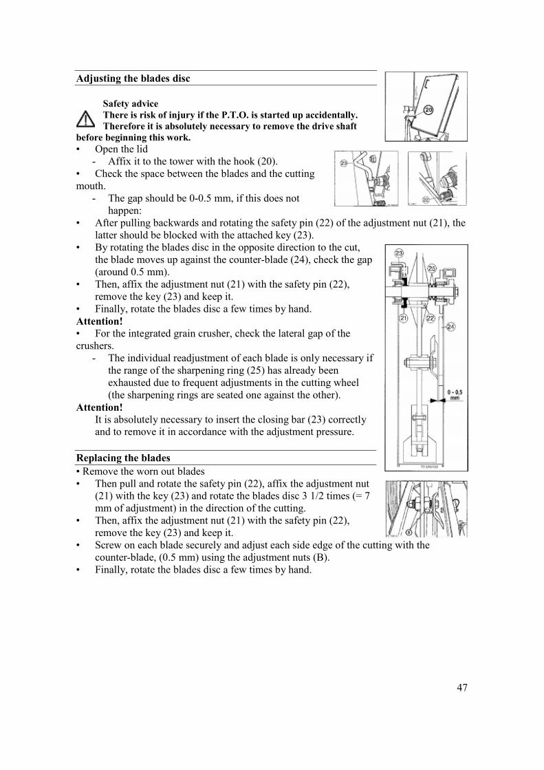
Adjusting the blades disc
Replacement of the blades and counter-blade
Installation of the corn chopper kit
Maintenance care (oil levels/winter storage)
Tuning the currents of the corn head
Clutch of the corn head (tuning)
Tuning the belts of the lateral spindles
Maintenance of the grass pickup (Lubrication/Tuning of the chains)
General lubrication
Breakdowns and possible solutions.
Possible breakdowns and their solutions
Breakdowns and solutions for electrical faults
Hydraulic scheme of the functioning of the machine
Cardans
Transmission cardan PTO-options
Declarations
“EC” compliance declaration
42/43
44
45
46
47
47/48
49/50
51
52/53
53/54
54
55/56
57/58/59/60
-- 61/62 63 64 -- 65/66 -- 67
4
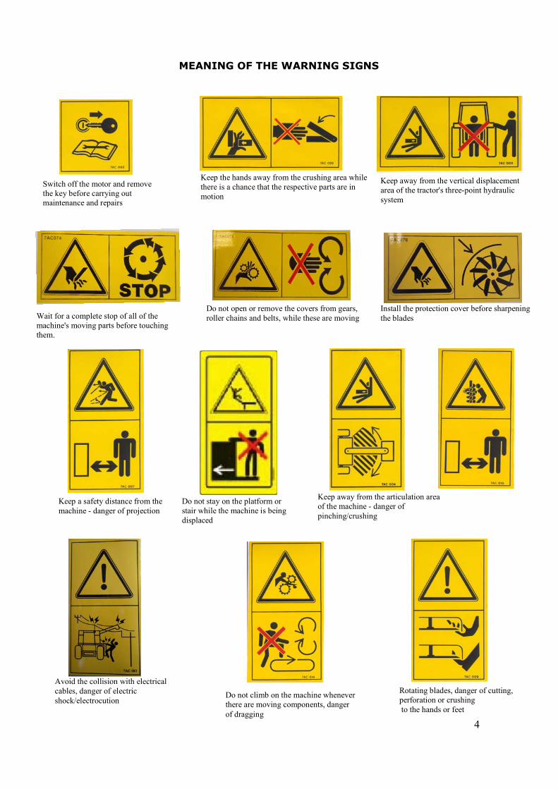
MEANING OF THE WARNING SIGNS
Switch off the motor and remove the key before carrying out maintenance and repairs
Keep the hands away from the crushing area while there is a chance that the respective parts are in motion
Keep away from the vertical displacement area of the tractor's three-point hydraulic system
Wait for a complete stop of all of the machine's moving parts before touching them.
Do not open or remove the covers from gears, roller chains and belts, while these are moving
Install the protection cover before sharpening the blades
Keep a safety distance from the machine - danger of projection
Keep away from the articulation area of the machine - danger of pinching/crushing
Avoid the collision with electrical cables, danger of electric shock/electrocution
Do not climb on the machine whenever there are moving components, danger of dragging
Rotating blades, danger of cutting, perforation or crushing to the hands or feet
Do not stay on the platform or stair while the machine is being displaced
5
4
PUTTING INTO USE
General safety tips for the use of the machine
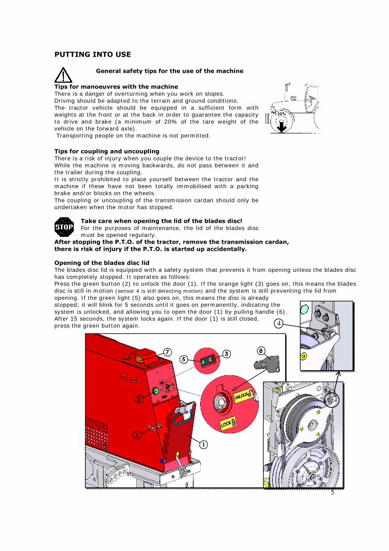
Tips for manoeuvres with the machine There is a danger of overturning when you work on slopes. Driving should be adapted to the terrain and ground conditions. The tractor vehicle should be equipped in a sufficient form with weights at the front or at the back in order to guarantee the capacity to drive and brake (a minimum of 20% of the tare weight of the vehicle on the forward axle). Transporting people on the machine is not permitted. Tips for coupling and uncoupling There is a risk of injury when you couple the device to the tractor! While the machine is moving backwards, do not pass between it and the trailer during the coupling. It is strictly prohibited to place yourself between the tractor and the machine if these have not been totally immobilised with a parking brake and/or blocks on the wheels. The coupling or uncoupling of the transmission cardan should only be undertaken when the motor has stopped.
Take care when opening the lid of the blades disc! For the purposes of maintenance, the lid of the blades disc must be opened regularly.
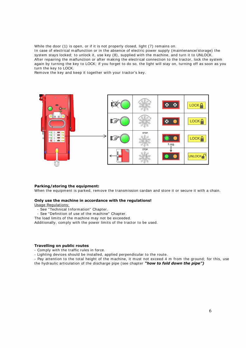
After stopping the P.T.O. of the tractor, remove the transmission cardan, there is risk of injury if the P.T.O. is started up accidentally. Opening of the blades disc lid The blades disc lid is equipped with a safety system that prevents it from opening unless the blades disc has completely stopped. It operates as follows: Press the green button (2) to unlock the door (1). If the orange light (3) goes on, this means the blades disc is still in motion (sensor 4 is still detecting motion) and the system is still preventing the lid from opening. If the green light (5) also goes on, this means the disc is already stopped; it will blink for 5 seconds until it goes on permanently, indicating the system is unlocked, and allowing you to open the door (1) by pulling handle (6). After 15 seconds, the system locks again. If the door (1) is still closed, press the green button again.
6
While the door (1) is open, or if it is not properly closed, light (7) remains on. In case of electrical malfunction or in the absence of electric power supply (maintenance/storage) the system stays locked; to unlock it, use key (8), supplied with the machine, and turn it to UNLOCK. After repairing the malfunction or after making the electrical connection to the tractor, lock the system again by turning the key to LOCK; if you forget to do so, the light will stay on, turning off as soon as you turn the key to LOCK. Remove the key and keep it together with your tractor's key. Parking/storing the equipment: When the equipment is parked, remove the transmission cardan and store it or secure it with a chain. Only use the machine in accordance with the regulations! Usage Regulations:
- See "Technical Information" Chapter. - See "Definition of use of the machine" Chapter.
The load limits of the machine may not be exceeded. Additionally, comply with the power limits of the tractor to be used. Travelling on public routes - Comply with the traffic rules in force. - Lighting devices should be installed, applied perpendicular to the route. - Pay attention to the total height of the machine, it must not exceed 4 m from the ground; for this, use the hydraulic articulation of the discharge pipe (see chapter “how to fold down the pipe”)
7
PUTTING INTO USE Before starting work a. Before starting work, the operator should have knowledge about all of the functioning devices
and their functions. It is too late to learn these aspects if work has already begun! b. The machine should be tested for safety in travelling and functioning before each operation. c. There is a danger of crushing or dismembering in the areas of the pickup, cutting unit, rear lid
and higher extension zones. Everyone should stand well back from these areas before the hydraulic equipment and the transmission are switched on.
d. Before driving the vehicle, the driver should ensure that no one is in danger and that there
are no obstructions. If the driver is not able to see and to have a general view of the road directly behind the machine, he should be helped by somebody during manoeuvres in reverse.
e. Comply with the safety tips in relation to the machine. You may find an explanation of the
meaning of the graphic warning symbols on page 4. f. Comply also with the tips in the relevant chapters and in the supplement to this functioning
manual. g. Check the hydraulic hoses regularly and replace old and damaged hydraulic hoses. The
replacement hoses should comply with the technical requirements of the manufacturer. h. For all maintenance, service and modification works, switch off the transmission motor and
remove the universal transmission. Check before use
The following tips should make the operation of the machine simpler for you. You may find detailed information on specific points in the relevant chapters of this instruction manual.
1. Check that all of the safety equipment (covers, shields, etc.) is in good condition and installed
in the correct position. 2. Lubricate the machine in accordance with the lubrication scheme. Check the oil levels. 3. Check the correct rpm of the P.T.O. 4. Carry out the electrical connections to the tractor and check whether they are correct. Take
note of the tips in the instruction manual! 5. Carry out the coupling of the machine to the 3 points of the tractor, at the front or at the
back, as required; in order to do this, see chapter “Coupling the machine to the tractor”. 6. Affix the machine using only the fittings supplied. 7. Install the transmission P.T.O. between the tractor and the machine. See chapter “Coupling
the machine to the tractor”.

8
8. Check the functioning of the electric controls. 9. Connect the hydraulic hoses to the tractor.
- Check the hydraulic hoses against the existence of damages and wear and tear. - Certify that the connections are correct.
9
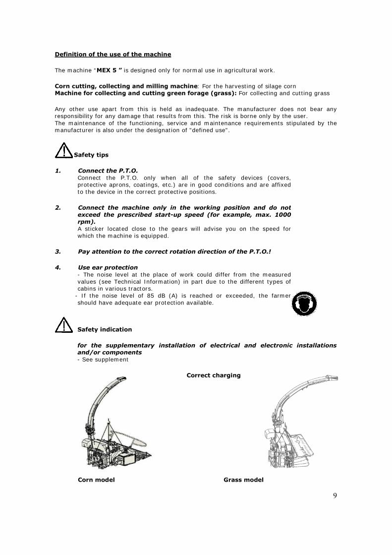
Definition of the use of the machine The machine “MEX 5 ” is designed only for normal use in agricultural work. Corn cutting, collecting and milling machine: For the harvesting of silage corn Machine for collecting and cutting green forage (grass): For collecting and cutting grass Any other use apart from this is held as inadequate. The manufacturer does not bear any responsibility for any damage that results from this. The risk is borne only by the user. The maintenance of the functioning, service and maintenance requirements stipulated by the manufacturer is also under the designation of "defined use".
Safety tips
1. Connect the P.T.O. Connect the P.T.O. only when all of the safety devices (covers,protective aprons, coatings, etc.) are in good conditions and are affixed to the device in the correct protective positions.
2. Connect the machine only in the working position and do not
exceed the prescribed start-up speed (for example, max. 1000 rpm). A sticker located close to the gears will advise you on the speed for which the machine is equipped.
3. Pay attention to the correct rotation direction of the P.T.O.! 4. Use ear protection
- The noise level at the place of work could differ from the measuredvalues (see Technical Information) in part due to the different types of cabins in various tractors.
- If the noise level of 85 dB (A) is reached or exceeded, the farmershould have adequate ear protection available.
Safety indication for the supplementary installation of electrical and electronic installationsand/or components - See supplement
Correct charging
Corn model Grass model
10
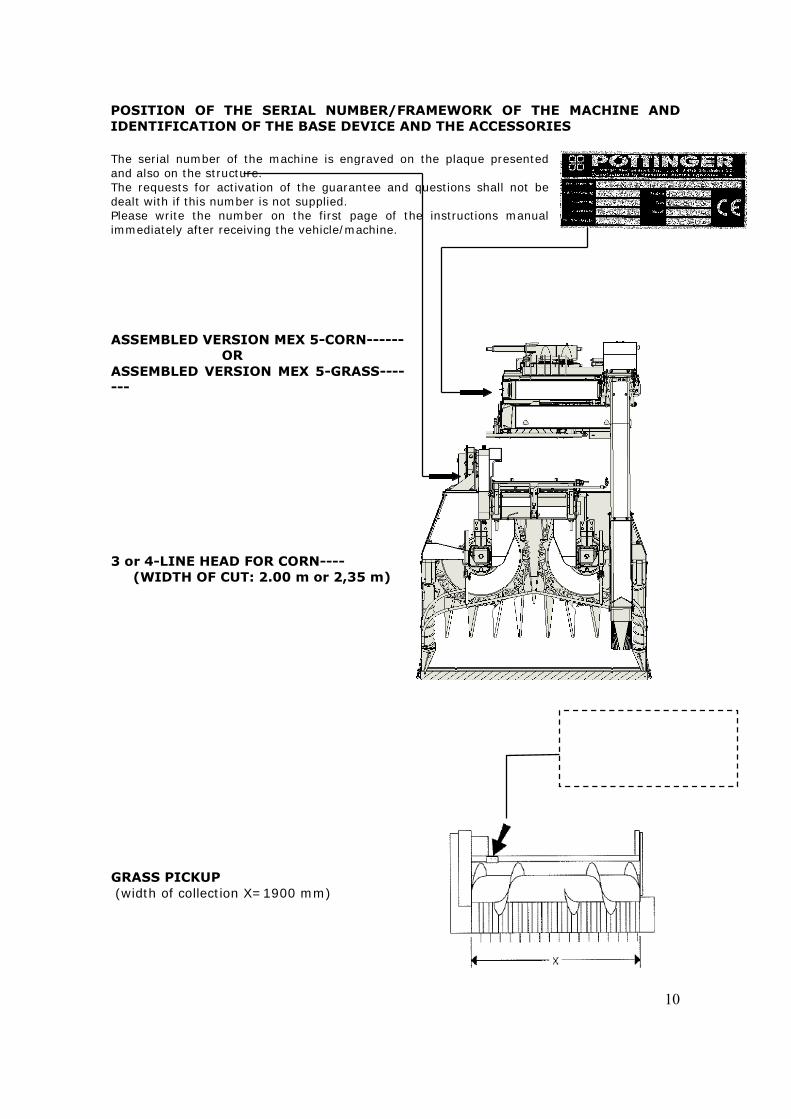
POSITION OF THE SERIAL NUMBER/FRAMEWORK OF THE MACHINE AND IDENTIFICATION OF THE BASE DEVICE AND THE ACCESSORIES The serial number of the machine is engraved on the plaque presentedand also on the structure. The requests for activation of the guarantee and questions shall not be dealt with if this number is not supplied. Please write the number on the first page of the instructions manualimmediately after receiving the vehicle/machine.
ASSEMBLED VERSION MEX 5-CORN------ OR ASSEMBLED VERSION MEX 5-GRASS------- 3 or 4-LINE HEAD FOR CORN---- (WIDTH OF CUT: 2.00 m or 2,35 m) GRASS PICKUP (width of collection X=1900 mm)
11
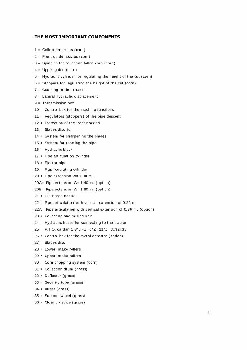
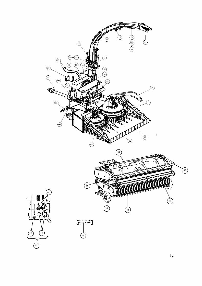
THE MOST IMPORTANT COMPONENTS
1 = Collection drums (corn)
2 = Front guide nozzles (corn)
3 = Spindles for collecting fallen corn (corn)
4 = Upper guide (corn)
5 = Hydraulic cylinder for regulating the height of the cut (corn)
6 = Stoppers for regulating the height of the cut (corn)
7 = Coupling to the tractor
8 = Lateral hydraulic displacement
9 = Transmission box
10 = Control box for the machine functions
11 = Regulators (stoppers) of the pipe descent
12 = Protection of the front nozzles
13 = Blades disc lid
14 = System for sharpening the blades
15 = System for rotating the pipe
16 = Hydraulic block
17 = Pipe articulation cylinder
18 = Ejector pipe
19 = Flap regulating cylinder
20 = Pipe extension W=1.00 m.
20A= Pipe extension W=1.40 m. (option)
20B= Pipe extension W=1.80 m. (option)
21 = Discharge nozzle
22 = Pipe articulation with vertical extension of 0.21 m.
22A= Pipe articulation with vertical extension of 0.76 m. (option)
23 = Collecting and milling unit
24 = Hydraulic hoses for connecting to the tractor
25 = P.T.O. cardan 1 3/8”-Z=6/Z=21/Z=8x32x38
26 = Control box for the metal detector (option)
27 = Blades disc
28 = Lower intake rollers
29 = Upper intake rollers
30 = Corn chopping system (corn)
31 = Collection drum (grass)
32 = Deflector (grass)
33 = Security tube (grass)
34 = Auger (grass)
35 = Support wheel (grass)
36 = Closing device (grass)
12
27 28 30
29
23
20B
36
35 31
32
34
33
13
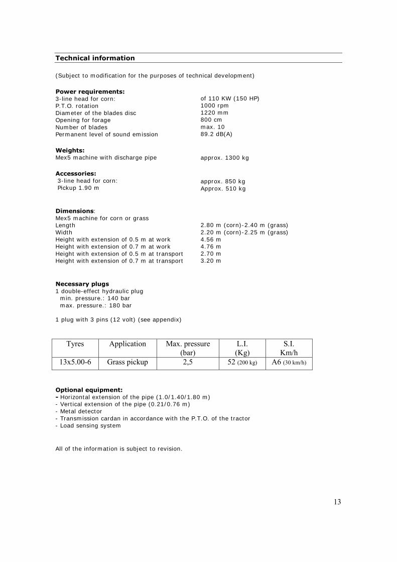
Technical information (Subject to modification for the purposes of technical development) Power requirements: 3-line head for corn: P.T.O. rotation Diameter of the blades disc Opening for forage Number of blades Permanent level of sound emission Weights: Mex5 machine with discharge pipe Accessories: 3-line head for corn: Pickup 1.90 m Dimensions: Mex5 machine for corn or grass Length Width Height with extension of 0.5 m at work Height with extension of 0.7 m at work Height with extension of 0.5 m at transport Height with extension of 0.7 m at transport Necessary plugs 1 double-effect hydraulic plug
min. pressure.: 140 bar max. pressure.: 180 bar
1 plug with 3 pins (12 volt) (see appendix)
of 110 KW (150 HP) 1000 rpm 1220 mm 800 cm max. 10 89.2 dB(A) approx. 1300 kg approx. 850 kg Approx. 510 kg 2.80 m (corn)-2.40 m (grass) 2.20 m (corn)-2.25 m (grass) 4.56 m 4.76 m 2.70 m 3.20 m
Tyres Application Max. pressure (bar)
L.I. (Kg)
S.I. Km/h
13x5.00-6 Grass pickup 2,5 52 (200 kg) A6 (30 km/h)
Optional equipment: - Horizontal extension of the pipe (1.0/1.40/1.80 m) - Vertical extension of the pipe (0.21/0.76 m) - Metal detector - Transmission cardan in accordance with the P.T.O. of the tractor - Load sensing system All of the information is subject to revision.
14
FIRST CONNECTION TO THE TRACTOR
HYDRAULIC CONNECTION
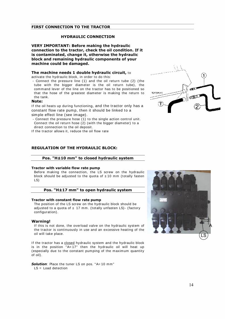
VERY IMPORTANT: Before making the hydraulic connection to the tractor, check the oil condition. If it is contaminated, change it, otherwise the hydraulic block and remaining hydraulic components of your machine could be damaged. The machine needs 1 double hydraulic circuit, to activate the hydraulic block, in order to do this: - Connect the pressure line (1) and the oil return tube (2) (the
tube with the bigger diameter is the oil return tube), the command lever of the line on the tractor has to be positioned so that the hose of the greatest diameter is making the return to the tank.
Note: If the oil heats up during functioning, and the tractor only has a constant flow rate pump, then it should be linked to a simple effect line (see image). - Connect the pressure hose (1) to the single action control unit.
Connect the oil return hose (2) (with the bigger diameter) to a direct connection to the oil deposit.
If the tractor allows it, reduce the oil flow rate REGULATION OF THE HYDRAULIC BLOCK:
Pos. "H±10 mm" to closed hydraulic system Tractor with variable flow rate pump
Before making the connection, the LS screw on the hydraulic block should be adjusted to the quota of ±10 mm (totally fasten LS)
Pos. "H±17 mm" to open hydraulic system
Tractor with constant flow rate pump
The position of the LS screw on the hydraulic block should be adjusted to a quota of ± 17 mm. (totally unfasten LS)- (factory configuration).
Warning! If this is not done, the overload valve on the hydraulic system of the tractor is continuously in use and an excessive heating of the oil will take place.
If the tractor has a closed hydraulic system and the hydraulic block is in the position "A=17" then the hydraulic oil will heat up (especially due to the constant pumping of the maximum quantity of oil).
Solution: Place the tuner LS on pos. “A=10 mm”
LS = Load detection
LS
A
15
PLs
R
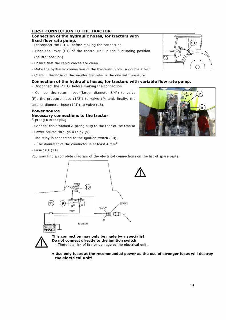
FIRST CONNECTION TO THE TRACTOR Connection of the hydraulic hoses, for tractors with fixed flow rate pump. - Disconnect the P.T.O. before making the connection
- Place the lever (ST) of the control unit in the fluctuating position
(neutral position),
- Ensure that the rapid valves are clean.
- Make the hydraulic connection of the hydraulic block. A double effect
- Check if the hose of the smaller diameter is the one with pressure.
Connection of the hydraulic hoses, for tractors with variable flow rate pump. - Disconnect the P.T.O. before making the connection
- Connect the return hose (larger diameter-3/4”) to valve
(R), the pressure hose (1/2”) to valve (P) and, finally, the
smaller diameter hose (1/4”) to valve (LS).
Power source Necessary connections to the tractor 3-prong current plug
- Connect the attached 3-prong plug to the rear of the tractor
- Power source through a relay (9)
The relay is connected to the ignition switch (10).
- The diameter of the conductor is at least 4 mm2
- Fuse 16A (11)
You may find a complete diagram of the electrical connections on the list of spare parts.
This connection may only be made by a specialist Do not connect directly to the ignition switch
- There is a risk of fire or damage to the electrical unit. • Use only fuses at the recommended power as the use of stronger fuses will destroy
the electrical unit!
16
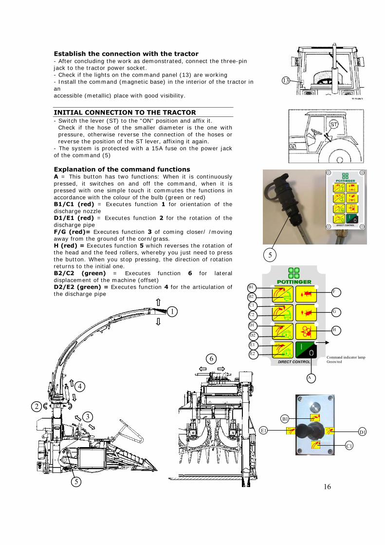
Establish the connection with the tractor- After concluding the work as demonstrated, connect the three-pin jack to the tractor power socket. - Check if the lights on the command panel (13) are working - Install the command (magnetic base) in the interior of the tractor in an accessible (metallic) place with good visibility. INITIAL CONNECTION TO THE TRACTOR - Switch the lever (ST) to the "ON" position and affix it.
Check if the hose of the smaller diameter is the one with pressure, otherwise reverse the connection of the hoses or reverse the position of the ST lever, affixing it again.
- The system is protected with a 15A fuse on the power jack of the command (5) Explanation of the command functions A = This button has two functions: When it is continuously pressed, it switches on and off the command, when it is pressed with one simple touch it commutes the functions in accordance with the colour of the bulb (green or red) B1/C1 (red) = Executes function 1 for orientation of the discharge nozzle D1/E1 (red) = Executes function 2 for the rotation of the discharge pipe F/G (red)= Executes function 3 of coming closer/ /moving away from the ground of the corn/grass. H (red) = Executes function 5 which reverses the rotation of the head and the feed rollers, whereby you just need to press the button. When you stop pressing, the direction of rotation returns to the initial one. B2/C2 (green) = Executes function 6 for lateral displacement of the machine (offset) D2/E2 (green) = Executes function 4 for the articulation of the discharge pipe
5
6
1
4
2 3
5
13
Command indicator lampGreen/red
F
G
H
A
B1
B2
C1
C2
D1
D2
E1
E2
D1 E1
B1
C1
17
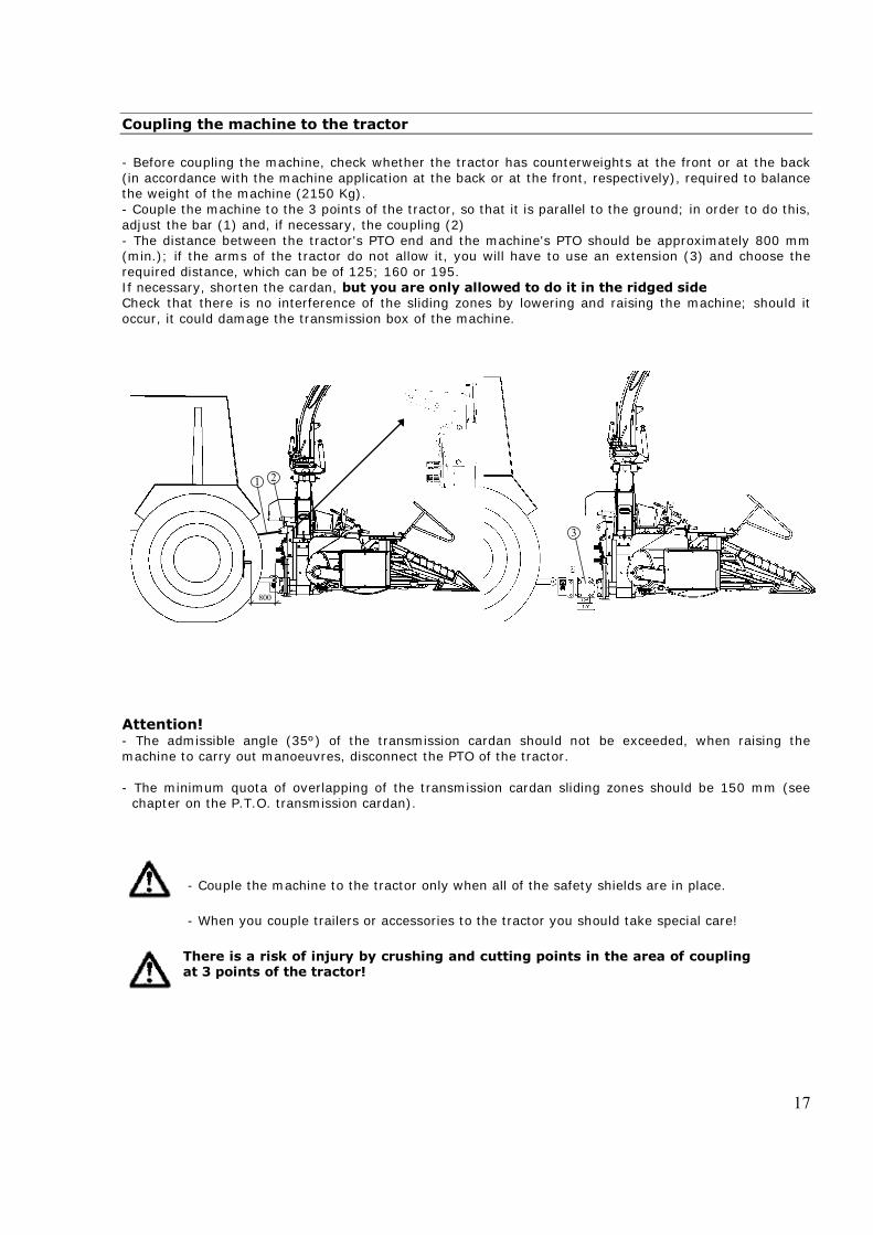
Coupling the machine to the tractor - Before coupling the machine, check whether the tractor has counterweights at the front or at the back (in accordance with the machine application at the back or at the front, respectively), required to balance the weight of the machine (2150 Kg). - Couple the machine to the 3 points of the tractor, so that it is parallel to the ground; in order to do this, adjust the bar (1) and, if necessary, the coupling (2) - The distance between the tractor's PTO end and the machine's PTO should be approximately 800 mm (min.); if the arms of the tractor do not allow it, you will have to use an extension (3) and choose the required distance, which can be of 125; 160 or 195. If necessary, shorten the cardan, but you are only allowed to do it in the ridged side Check that there is no interference of the sliding zones by lowering and raising the machine; should it occur, it could damage the transmission box of the machine.
Attention! - The admissible angle (35º) of the transmission cardan should not be exceeded, when raising the machine to carry out manoeuvres, disconnect the PTO of the tractor. - The minimum quota of overlapping of the transmission cardan sliding zones should be 150 mm (see
chapter on the P.T.O. transmission cardan).
- Couple the machine to the tractor only when all of the safety shields are in place. - When you couple trailers or accessories to the tractor you should take special care!
There is a risk of injury by crushing and cutting points in the area of couplingat 3 points of the tractor!
3
800
1 2
18
1
3 2
4
2
3 4 1
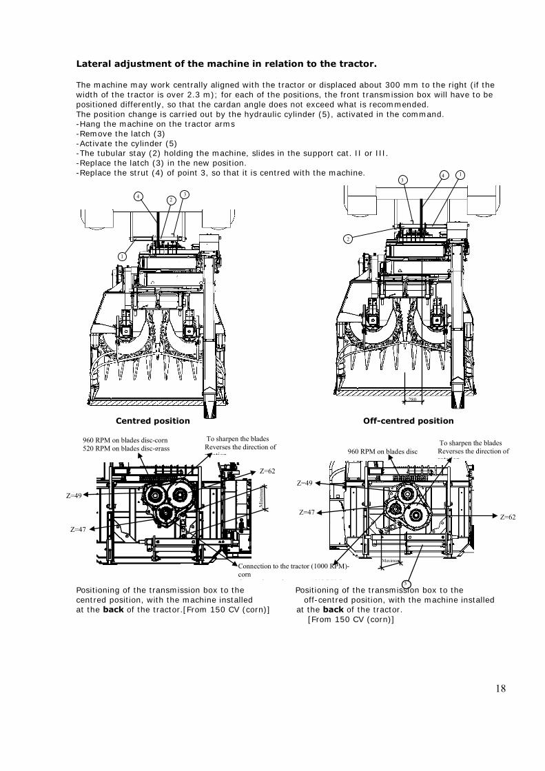
Lateral adjustment of the machine in relation to the tractor. The machine may work centrally aligned with the tractor or displaced about 300 mm to the right (if the width of the tractor is over 2.3 m); for each of the positions, the front transmission box will have to be positioned differently, so that the cardan angle does not exceed what is recommended. The position change is carried out by the hydraulic cylinder (5), activated in the command. -Hang the machine on the tractor arms -Remove the latch (3) -Activate the cylinder (5) -The tubular stay (2) holding the machine, slides in the support cat. II or III. -Replace the latch (3) in the new position. -Replace the strut (4) of point 3, so that it is centred with the machine. Centred position Off-centred position Positioning of the transmission box to the Positioning of the transmission box to the centred position, with the machine installed off-centred position, with the machine installed at the back of the tractor.[From 150 CV (corn)] at the back of the tractor. [From 150 CV (corn)]
280
5
5
Maximum
960 RPM on blades disc To sharpen the blades Reverses the direction of rotation
Z=62
Z=49
Z=47
Min
imum
Connection to the tractor (1000 RPM)-corn C ti t th t t (540 RPM)
960 RPM on blades disc-corn 520 RPM on blades disc-grass
To sharpen the blades Reverses the direction of rotation
Z=49
Z=47
Z=62
19
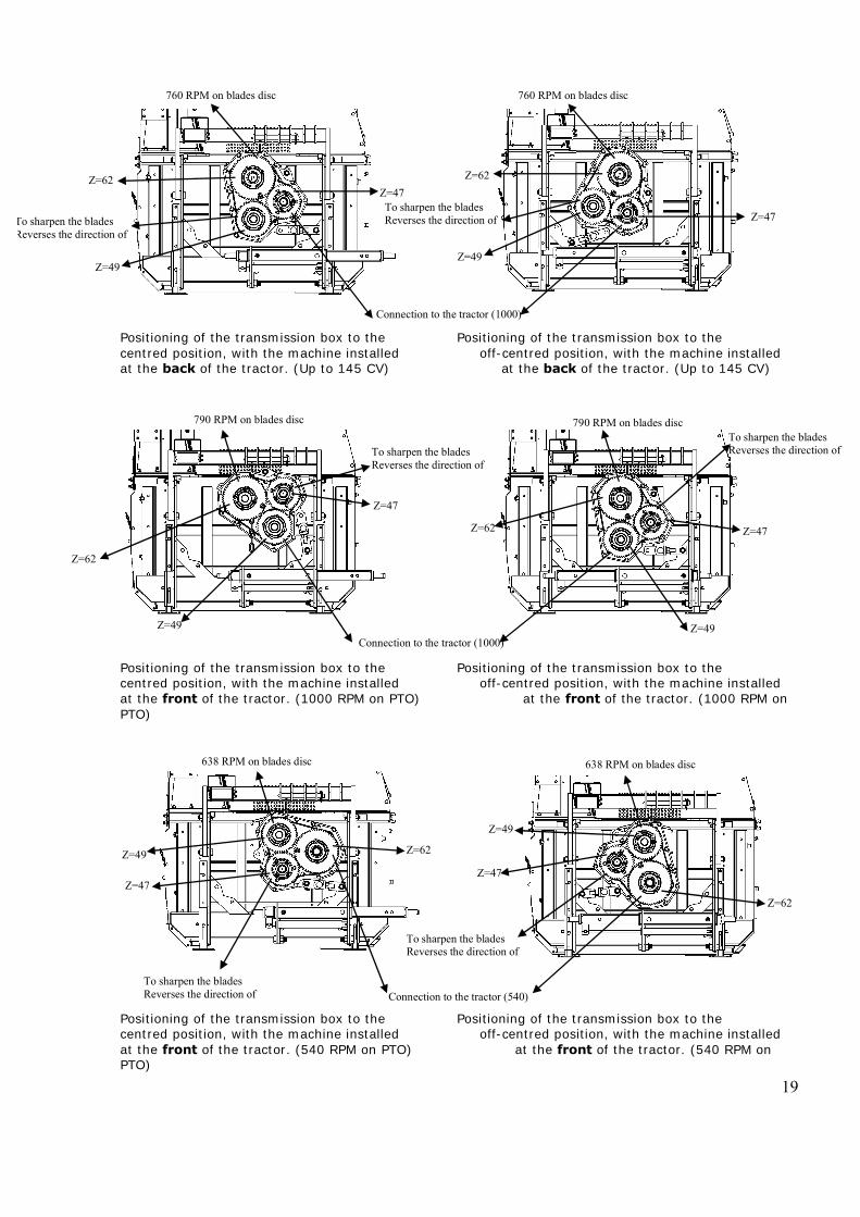
Positioning of the transmission box to the Positioning of the transmission box to the centred position, with the machine installed off-centred position, with the machine installed at the back of the tractor. (Up to 145 CV) at the back of the tractor. (Up to 145 CV) Positioning of the transmission box to the Positioning of the transmission box to the centred position, with the machine installed off-centred position, with the machine installed at the front of the tractor. (1000 RPM on PTO) at the front of the tractor. (1000 RPM on PTO) Positioning of the transmission box to the Positioning of the transmission box to the centred position, with the machine installed off-centred position, with the machine installed at the front of the tractor. (540 RPM on PTO) at the front of the tractor. (540 RPM on PTO)
Connection to the tractor (1000)
Z=62
Z=49
Z=47
Z=62
Z=49
Z=47
760 RPM on blades disc 760 RPM on blades disc
To sharpen the blades Reverses the direction of To sharpen the blades
Reverses the direction of
Z=62 Z=49
638 RPM on blades disc
To sharpen the blades Reverses the direction of Connection to the tractor (540)
Z=62
Z=47 Z=47
To sharpen the blades Reverses the direction of
Z=49
638 RPM on blades disc
Z=62
Z=49
790 RPM on blades disc
To sharpen the blades Reverses the direction of
Z=47
Connection to the tractor (1000)
790 RPM on blades disc
Z=62
Z=49
Z=47
To sharpen the blades Reverses the direction of
20
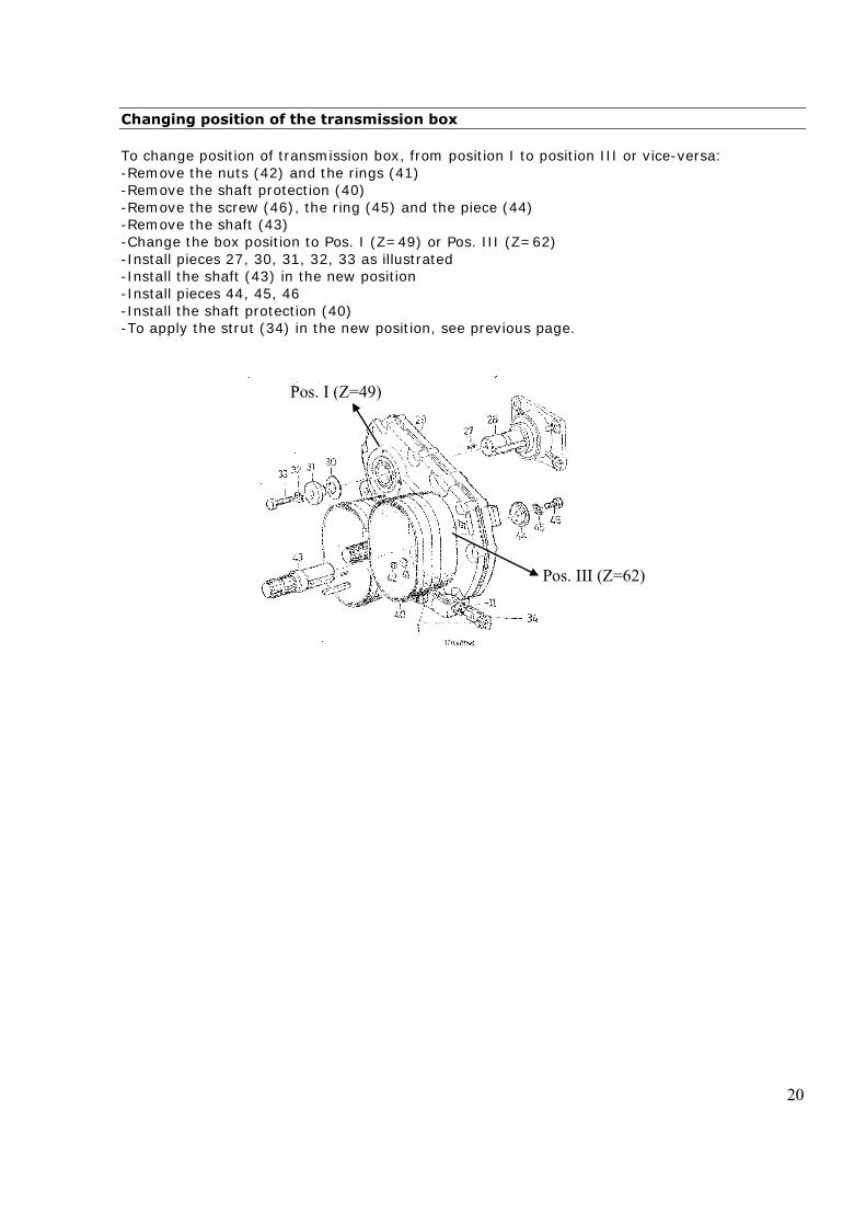
Changing position of the transmission box To change position of transmission box, from position I to position III or vice-versa: -Remove the nuts (42) and the rings (41) -Remove the shaft protection (40) -Remove the screw (46), the ring (45) and the piece (44) -Remove the shaft (43) -Change the box position to Pos. I (Z=49) or Pos. III (Z=62) -Install pieces 27, 30, 31, 32, 33 as illustrated -Install the shaft (43) in the new position -Install pieces 44, 45, 46 -Install the shaft protection (40) -To apply the strut (34) in the new position, see previous page.
Pos. I (Z=49)
Pos. III (Z=62)
21
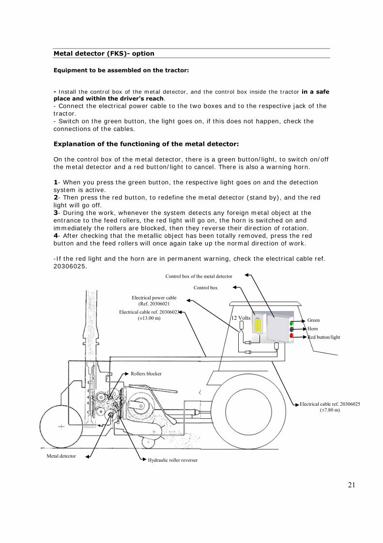
Metal detector (FKS)- option Equipment to be assembled on the tractor: - Install the control box of the metal detector, and the control box inside the tractor in a safe place and within the driver's reach. - Connect the electrical power cable to the two boxes and to the respective jack of the tractor. - Switch on the green button, the light goes on, if this does not happen, check the connections of the cables. Explanation of the functioning of the metal detector: On the control box of the metal detector, there is a green button/light, to switch on/off the metal detector and a red button/light to cancel. There is also a warning horn. 1- When you press the green button, the respective light goes on and the detection system is active. 2- Then press the red button, to redefine the metal detector (stand by), and the red light will go off. 3- During the work, whenever the system detects any foreign metal object at the entrance to the feed rollers, the red light will go on, the horn is switched on and immediately the rollers are blocked, then they reverse their direction of rotation. 4- After checking that the metallic object has been totally removed, press the red button and the feed rollers will once again take up the normal direction of work. -If the red light and the horn are in permanent warning, check the electrical cable ref. 20306025.
12 Volts Green
Red button/light
Horn
Rollers blocker
Metal detector Hydraulic roller reverser
Electrical cable ref. 20306025 (±7.80 m)
Electrical cable ref. 20306023 (±13.00 m)
Control box
Control box of the metal detector
Electrical power cable (Ref. 20306021

22
Maintenance note: When you undertake any soldering work on the machine equipped with a metal detector, there is a risk of magnetisation. If the metal detector is not working correctly, it will have to be demagnetised; in order to obtain help, contact our after-sales service.
23
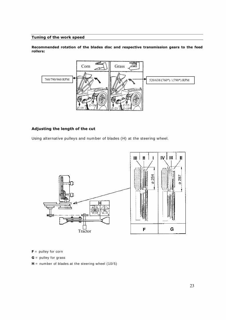
Tuning of the work speed Recommended rotation of the blades disc and respective transmission gears to the feed rollers:
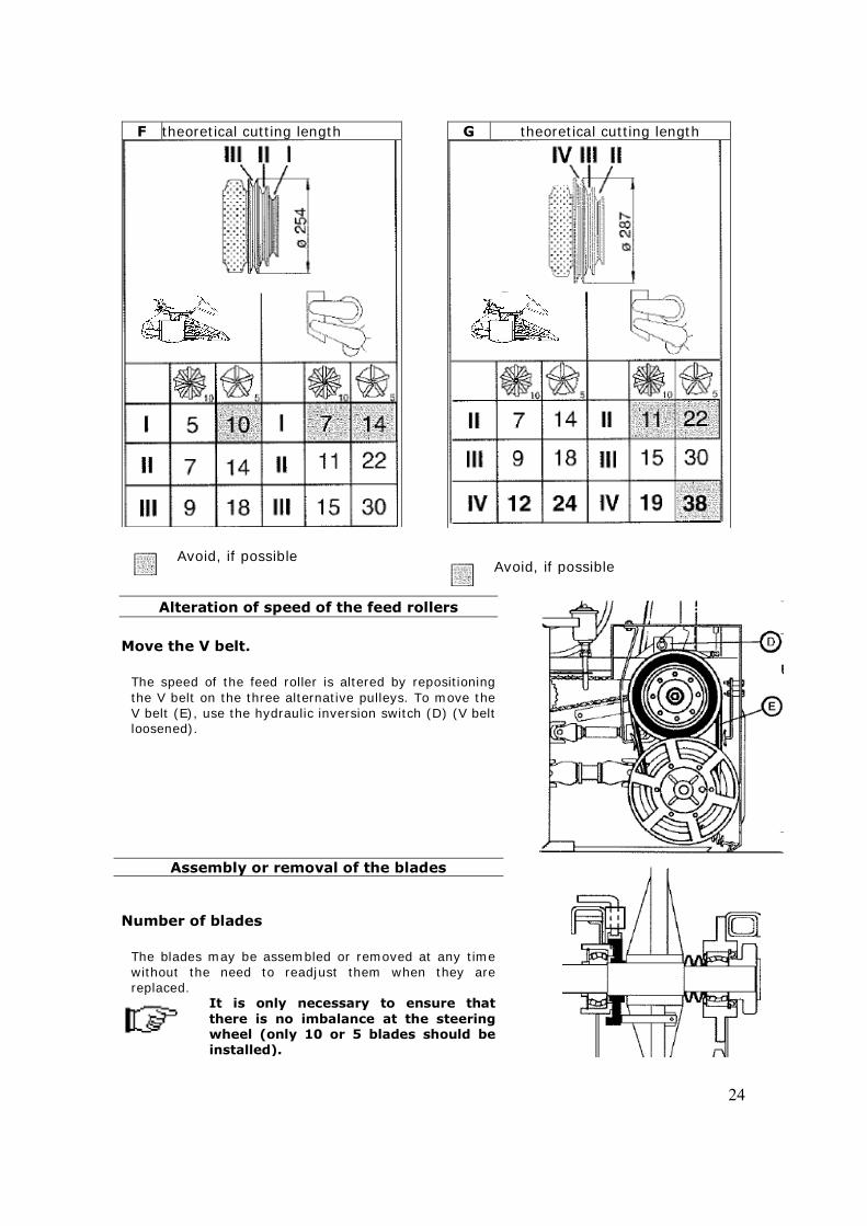
Adjusting the length of the cut Using alternative pulleys and number of blades (H) at the steering wheel.
F = pulley for corn
G = pulley for grass
H = number of blades at the steering wheel (10/5)
Corn Grass
760/790/960 RPM 520/638/(760*) / (790*) RPM
Z=19 Z=19
Z=23 Z=15 Z=19*
Tractor
24
F theoretical cutting length
Avoid, if possible
G theoretical cutting length
Avoid, if possible
Alteration of speed of the feed rollers Move the V belt.
The speed of the feed roller is altered by repositioning the V belt on the three alternative pulleys. To move the V belt (E), use the hydraulic inversion switch (D) (V belt loosened).
Assembly or removal of the blades Number of blades
The blades may be assembled or removed at any time without the need to readjust them when they are replaced.
It is only necessary to ensure that there is no imbalance at the steering wheel (only 10 or 5 blades should be installed).
25
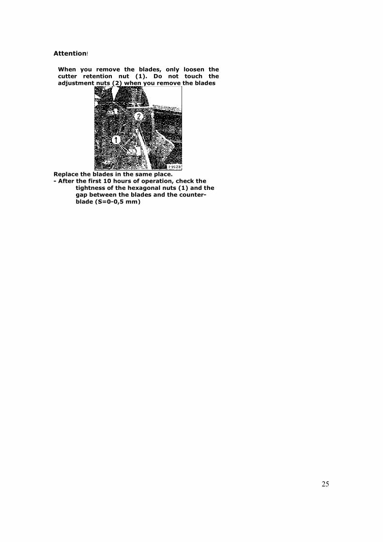
Attention!
When you remove the blades, only loosen the cutter retention nut (1). Do not touch the adjustment nuts (2) when you remove the blades
Replace the blades in the same place. - After the first 10 hours of operation, check the
tightness of the hexagonal nuts (1) and the gap between the blades and the counter-blade (S=0-0,5 mm)
26
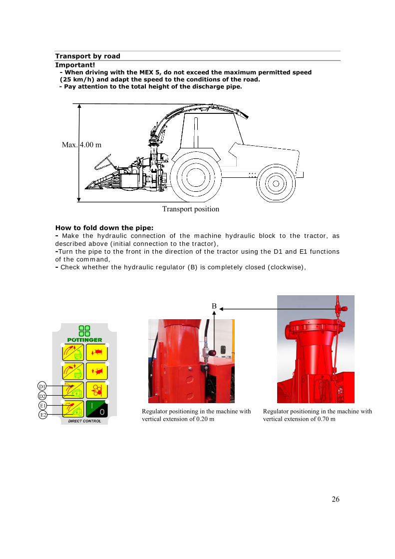
Transport by road Important!
- When driving with the MEX 5, do not exceed the maximum permitted speed (25 km/h) and adapt the speed to the conditions of the road.
- Pay attention to the total height of the discharge pipe. How to fold down the pipe: - Make the hydraulic connection of the machine hydraulic block to the tractor, as described above (initial connection to the tractor), -Turn the pipe to the front in the direction of the tractor using the D1 and E1 functions of the command, - Check whether the hydraulic regulator (B) is completely closed (clockwise),
Transport position
Max. 4.00 m
B
Regulator positioning in the machine with vertical extension of 0.20 m
Regulator positioning in the machine with vertical extension of 0.70 m
D1
E1
E2
D2
27
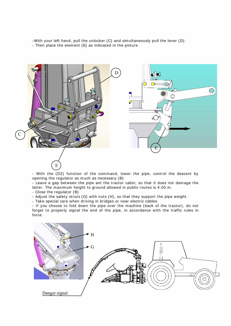
-With your left hand, pull the unlocker (C) and simultaneously pull the lever (D). - Then place the element (E) as indicated in the picture - With the (D2) function of the command, lower the pipe, control the descent by opening the regulator as much as necessary (B) - Leave a gap between the pipe ant the tractor cabin, so that it does not damage the latter. The maximum height to ground allowed in public routes is 4.00 m. - Close the regulator (B) - Adjust the safety struts (G) with nuts (H), so that they support the pipe weight. - Take special care when driving in bridges or near electric cables. - If you choose to fold down the pipe over the machine (back of the tractor), do not forget to properly signal the end of the pipe, in accordance with the traffic rules in force.
C
D
E
E
Danger signal
G
H
28
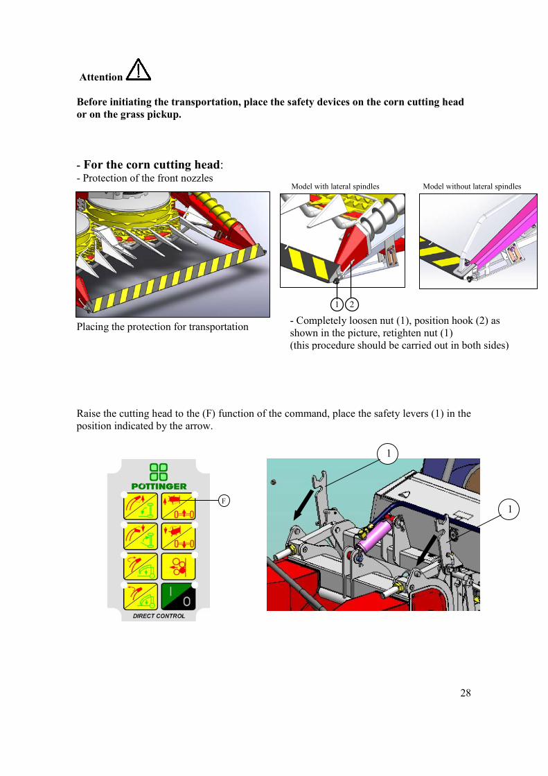
Attention Before initiating the transportation, place the safety devices on the corn cutting head or on the grass pickup. - For the corn cutting head: - Protection of the front nozzles
Placing the protection for transportation Raise the cutting head to the (F) function of the command, place the safety levers (1) in the position indicated by the arrow.
1
1
F
Model with lateral spindles Model without lateral spindles
1 2
- Completely loosen nut (1), position hook (2) as shown in the picture, retighten nut (1) (this procedure should be carried out in both sides)
29
1 2
3
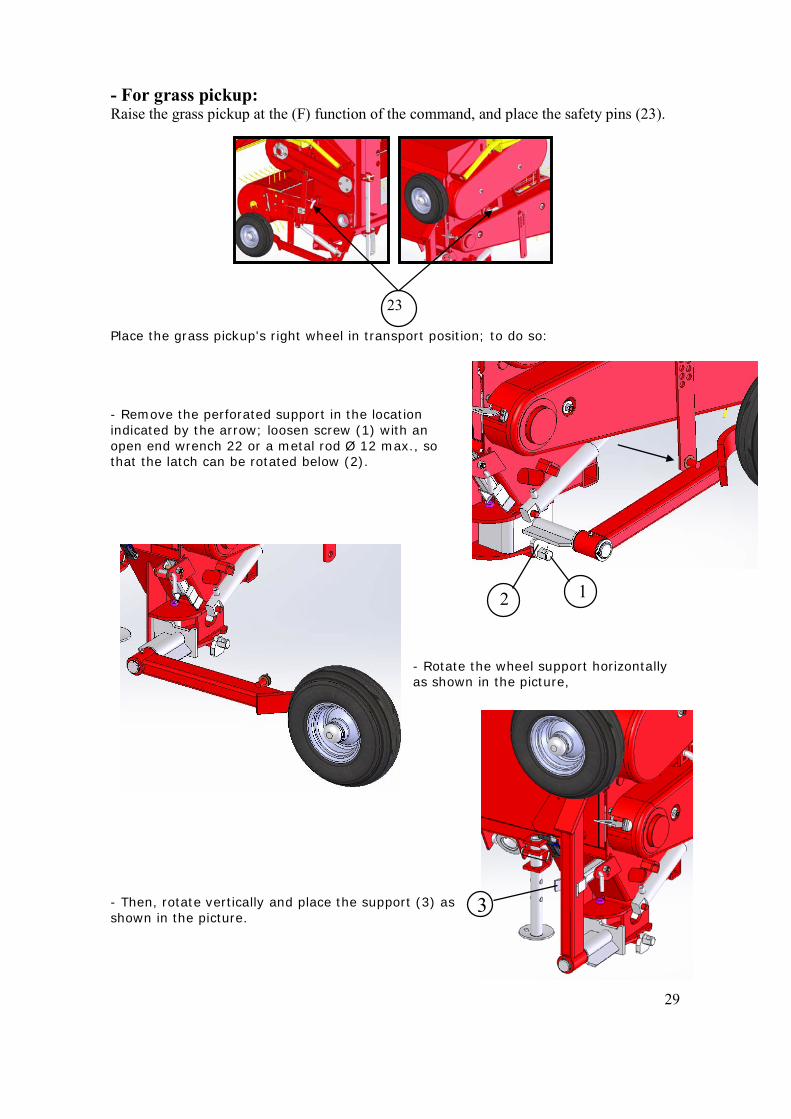
- For grass pickup: Raise the grass pickup at the (F) function of the command, and place the safety pins (23). Place the grass pickup's right wheel in transport position; to do so: - Remove the perforated support in the location indicated by the arrow; loosen screw (1) with an open end wrench 22 or a metal rod Ø 12 max., so that the latch can be rotated below (2).
- Rotate the wheel support horizontally as shown in the picture,
- Then, rotate vertically and place the support (3) as shown in the picture.
23
30
Operating in a field Working recommendations - Before commencing each work session, check whether all
of the screws and pins are tightened and whether the drive shaft was correctly assembled and stuck between the machine and the tractor.
- Switch off the tractor motor before working on the
machine (do not leave it simply disengaged). Your foot can easily slip from the pedal. "Wait for a complete stop".
- Adjust the working speed in accordance with the working
conditions. - During the operation of the machine, the permitted P.T.O.
rotation (1000 rpm) may not be exceeded. - When you remove blockages, never place yourself in
the danger zone at the power entrance to the accessories! Remove blockages by simply reversing the power or with the motor and the P.T.O. switched off!
- Manual charging is not permitted! - Control the beginning of the movement of the machine slowly with the tractor clutch to avoid damage. - Avoid placing yourself in the exhaust zone of the
machine! - Comply with the safety distance from overhead
electrical cables!
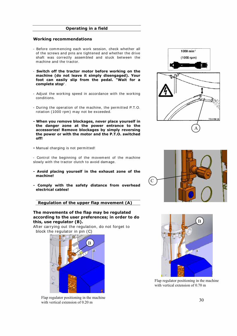
Regulation of the upper flap movement (A) The movements of the flap may be regulated according to the user preferences; in order to do this, use regulator (B). After carrying out the regulation, do not forget to
block the regulator in pin (C)
A
C
B
Flap regulator positioning in the machine with vertical extension of 0.20 m
Flap regulator positioning in the machine with vertical extension of 0.70 m
B
31
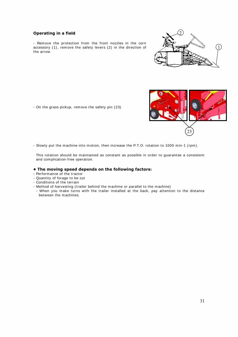
1 1
2
23
Operating in a field - Remove the protection from the front nozzles in the corn accessory (1), remove the safety levers (2) in the direction of the arrow. - On the grass pickup, remove the safety pin (23) - Slowly put the machine into motion, then increase the P.T.O. rotation to 1000 min-1 (rpm).
This rotation should be maintained as constant as possible in order to guarantee a consistent and complication-free operation.
• The moving speed depends on the following factors: - Performance of the tractor - Quantity of forage to be cut - Conditions of the terrain - Method of harvesting (trailer behind the machine or parallel to the machine)
- When you make turns with the trailer installed at the back, pay attention to the distance between the machines.
32
Corn cutting head for 4 lines
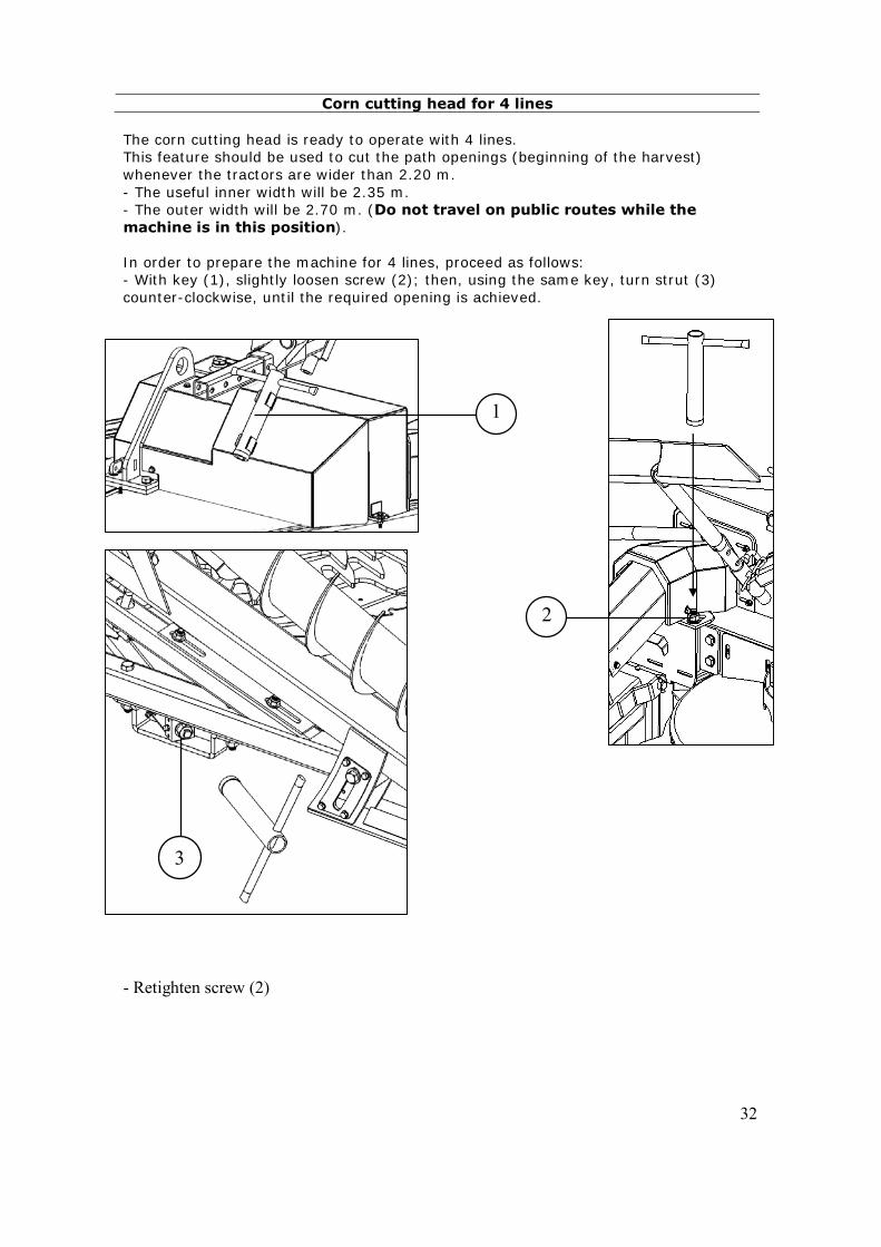
The corn cutting head is ready to operate with 4 lines. This feature should be used to cut the path openings (beginning of the harvest) whenever the tractors are wider than 2.20 m. - The useful inner width will be 2.35 m. - The outer width will be 2.70 m. (Do not travel on public routes while the machine is in this position). In order to prepare the machine for 4 lines, proceed as follows: - With key (1), slightly loosen screw (2); then, using the same key, turn strut (3) counter-clockwise, until the required opening is achieved. - Retighten screw (2)
2
1
3
33
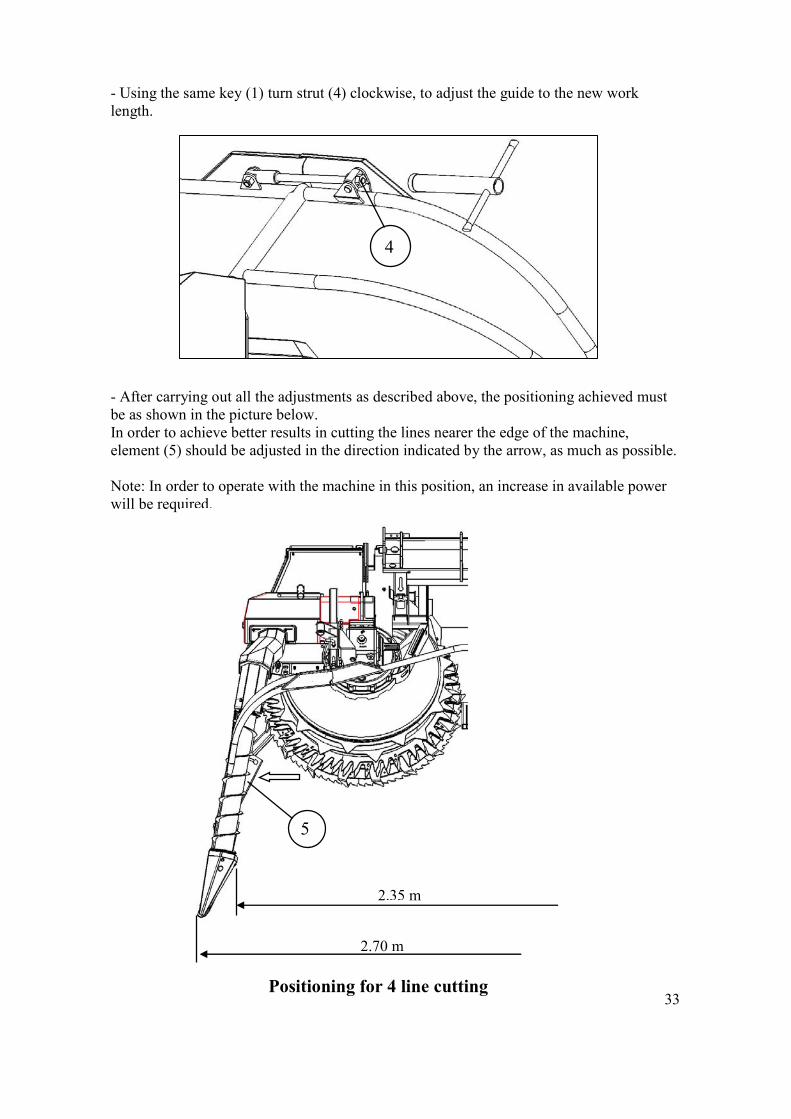
- Using the same key (1) turn strut (4) clockwise, to adjust the guide to the new work length. - After carrying out all the adjustments as described above, the positioning achieved must be as shown in the picture below. In order to achieve better results in cutting the lines nearer the edge of the machine, element (5) should be adjusted in the direction indicated by the arrow, as much as possible. Note: In order to operate with the machine in this position, an increase in available power will be required.
4
2.35 m
2.70 m
5
Positioning for 4 line cutting
34
Warning: Be particularly careful while manoeuvring the machine in this position (4 lines), since the machine will be wider than the tractor.
To return the machine to the 3-line position, proceed in the reverse order, as described above. If you choose to transport the machine in the "4 lines" position (not recommended, since the width is in excess of 2.50 m), install the front nozzles protection; to do so, adjust it to the machine's width. - Completely remove screw (1) and slightly loosen screws (2), install the protection as shown in the picture and retighten all screws.
2.00 m
2.25 m
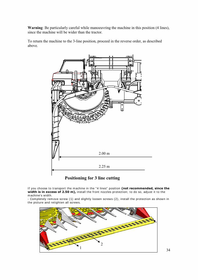
Positioning for 3 line cutting
1 2
35
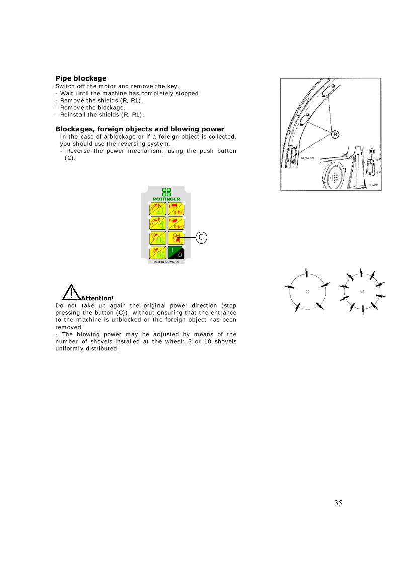
Pipe blockage Switch off the motor and remove the key. - Wait until the machine has completely stopped. - Remove the shields (R, R1). - Remove the blockage. - Reinstall the shields (R, R1). Blockages, foreign objects and blowing power
In the case of a blockage or if a foreign object is collected, you should use the reversing system. - Reverse the power mechanism, using the push button
(C).
Attention! Do not take up again the original power direction (stop pressing the button (C)), without ensuring that the entrance to the machine is unblocked or the foreign object has been removed - The blowing power may be adjusted by means of the number of shovels installed at the wheel: 5 or 10 shovels uniformly distributed.
C
36
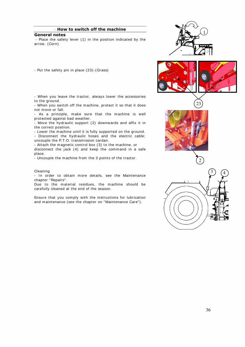
- How to switch off the machine General notes - Place the safety lever (1) in the position indicated by the arrow. (Corn) - Put the safety pin in place (23)-(Grass) - When you leave the tractor, always lower the accessories to the ground. - When you switch off the machine, protect it so that it does not move or fall. - As a principle, make sure that the machine is well protected against bad weather. - Move the hydraulic support (2) downwards and affix it in the correct position. - Lower the machine until it is fully supported on the ground. - Disconnect the hydraulic hoses and the electric cable; uncouple the P.T.O. transmission cardan. - Attach the magnetic control box (3) to the machine, or disconnect the jack (4) and keep the command in a safe place. - Uncouple the machine from the 3 points of the tractor. Cleaning - In order to obtain more details, see the Maintenance chapter "Repairs". Due to the material residues, the machine should be carefully cleaned at the end of the season. Ensure that you comply with the instructions for lubrication and maintenance (see the chapter on "Maintenance Care").
1
2
3 4
23
37
Assembly of the corn cutting head
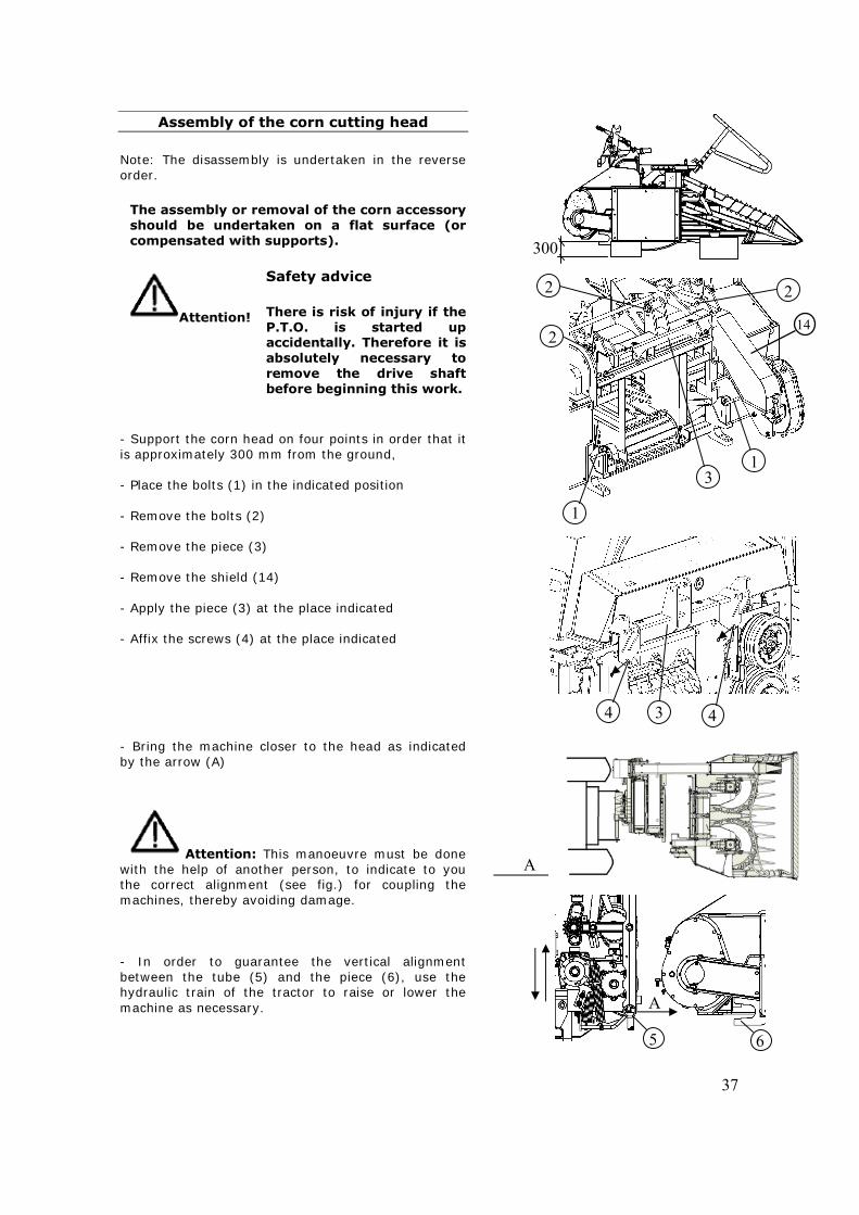
Note: The disassembly is undertaken in the reverse order.
The assembly or removal of the corn accessory should be undertaken on a flat surface (or compensated with supports).
Attention!
Safety advice There is risk of injury if the P.T.O. is started up accidentally. Therefore it is absolutely necessary to remove the drive shaft before beginning this work.
- Support the corn head on four points in order that it is approximately 300 mm from the ground, - Place the bolts (1) in the indicated position - Remove the bolts (2) - Remove the piece (3) - Remove the shield (14) - Apply the piece (3) at the place indicated - Affix the screws (4) at the place indicated - Bring the machine closer to the head as indicated by the arrow (A) Attention: This manoeuvre must be done with the help of another person, to indicate to you the correct alignment (see fig.) for coupling the machines, thereby avoiding damage. - In order to guarantee the vertical alignment between the tube (5) and the piece (6), use the hydraulic train of the tractor to raise or lower the machine as necessary.
3 4 4
300
A
A
5 6
1
1
22
2
3
14
38
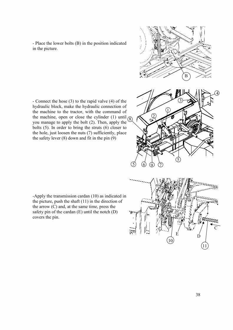
- Place the lower bolts (B) in the position indicated in the picture. - Connect the hose (3) to the rapid valve (4) of the hydraulic block, make the hydraulic connection of the machine to the tractor, with the command of the machine, open or close the cylinder (1) until you manage to apply the bolt (2). Then, apply the bolts (5). In order to bring the struts (6) closer to the hole, just loosen the nuts (7) sufficiently, place the safety lever (8) down and fit in the pin (9) -Apply the transmission cardan (10) as indicated in the picture, push the shaft (11) in the direction of the arrow (C) and, at the same time, press the safety pin of the cardan (E) until the notch (D) covers the pin.
B
1 2
3
4
55
6 79
8
D
C
10 11
E
39
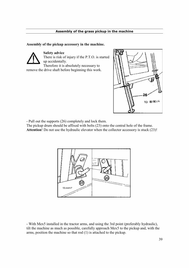
Assembly of the grass pickup in the machine
Assembly of the pickup accessory in the machine.
Safety advice There is risk of injury if the P.T.O. is started up accidentally. Therefore it is absolutely necessary to
remove the drive shaft before beginning this work. - Pull out the supports (26) completely and lock them. The pickup drum should be affixed with bolts (23) onto the central hole of the frame. Attention! Do not use the hydraulic elevator when the collector accessory is stuck (23)! - With Mex5 installed in the tractor arms, and using the 3rd point (preferably hydraulic), tilt the machine as much as possible, carefully approach Mex5 to the pickup and, with the arms, position the machine so that rod (1) is attached to the pickup.
40
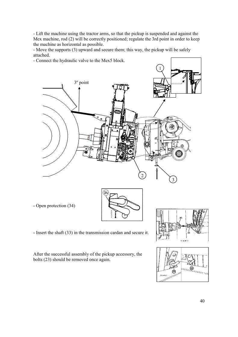
- Lift the machine using the tractor arms, so that the pickup is suspended and against the Mex machine, rod (2) will be correctly positioned; regulate the 3rd point in order to keep the machine as horizontal as possible. - Move the supports (3) upward and secure them; this way, the pickup will be safely attached. - Connect the hydraulic valve to the Mex5 block. - Open protection (34) - Insert the shaft (33) in the transmission cardan and secure it. After the successful assembly of the pickup accessory, the bolts (23) should be removed once again.
3º point
1
2 3
41
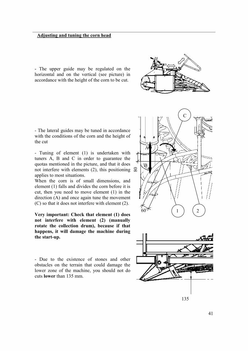
Adjusting and tuning the corn head - The upper guide may be regulated on the horizontal and on the vertical (see picture) in accordance with the height of the corn to be cut. - The lateral guides may be tuned in accordance with the conditions of the corn and the height of the cut - Tuning of element (1) is undertaken with tuners A, B and C in order to guarantee the quotas mentioned in the picture, and that it does not interfere with elements (2), this positioning applies to most situations. When the corn is of small dimensions, and element (1) falls and divides the corn before it is cut, then you need to move element (1) in the direction (A) and once again tune the movement (C) so that it does not interfere with element (2). Very important: Check that element (1) does not interfere with element (2) (manually rotate the collection drum), because if that happens, it will damage the machine during the start-up. - Due to the existence of stones and other obstacles on the terrain that could damage the lower zone of the machine, you should not do cuts lower than 135 mm.
A
B
C
1 2 60
80
135
42
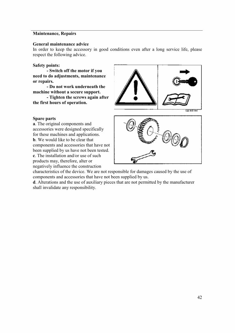
Maintenance, Repairs General maintenance advice In order to keep the accessory in good conditions even after a long service life, please respect the following advice. Safety points: - Switch off the motor if you need to do adjustments, maintenance or repairs. - Do not work underneath the machine without a secure support. - Tighten the screws again after the first hours of operation. Spare parts a. The original components and accessories were designed specifically for these machines and applications. b. We would like to be clear that components and accessories that have not been supplied by us have not been tested. c. The installation and/or use of such products may, therefore, alter or negatively influence the construction characteristics of the device. We are not responsible for damages caused by the use of components and accessories that have not been supplied by us. d. Alterations and the use of auxiliary pieces that are not permitted by the manufacturer shall invalidate any responsibility.
43
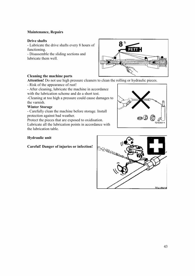
Maintenance, Repairs Drive shafts - Lubricate the drive shafts every 8 hours of functioning. - Disassemble the sliding sections and lubricate them well. Cleaning the machine parts Attention! Do not use high pressure cleaners to clean the rolling or hydraulic pieces. - Risk of the appearance of rust! - After cleaning, lubricate the machine in accordance with the lubrication scheme and do a short test. -Cleaning at too high a pressure could cause damages to the varnish. Winter Storage - Carefully clean the machine before storage. Install protection against bad weather. Protect the pieces that are exposed to oxidisation. Lubricate all the lubrication points in accordance with the lubrication table. Hydraulic unit Careful! Danger of injuries or infection!
44
3
A
B
C
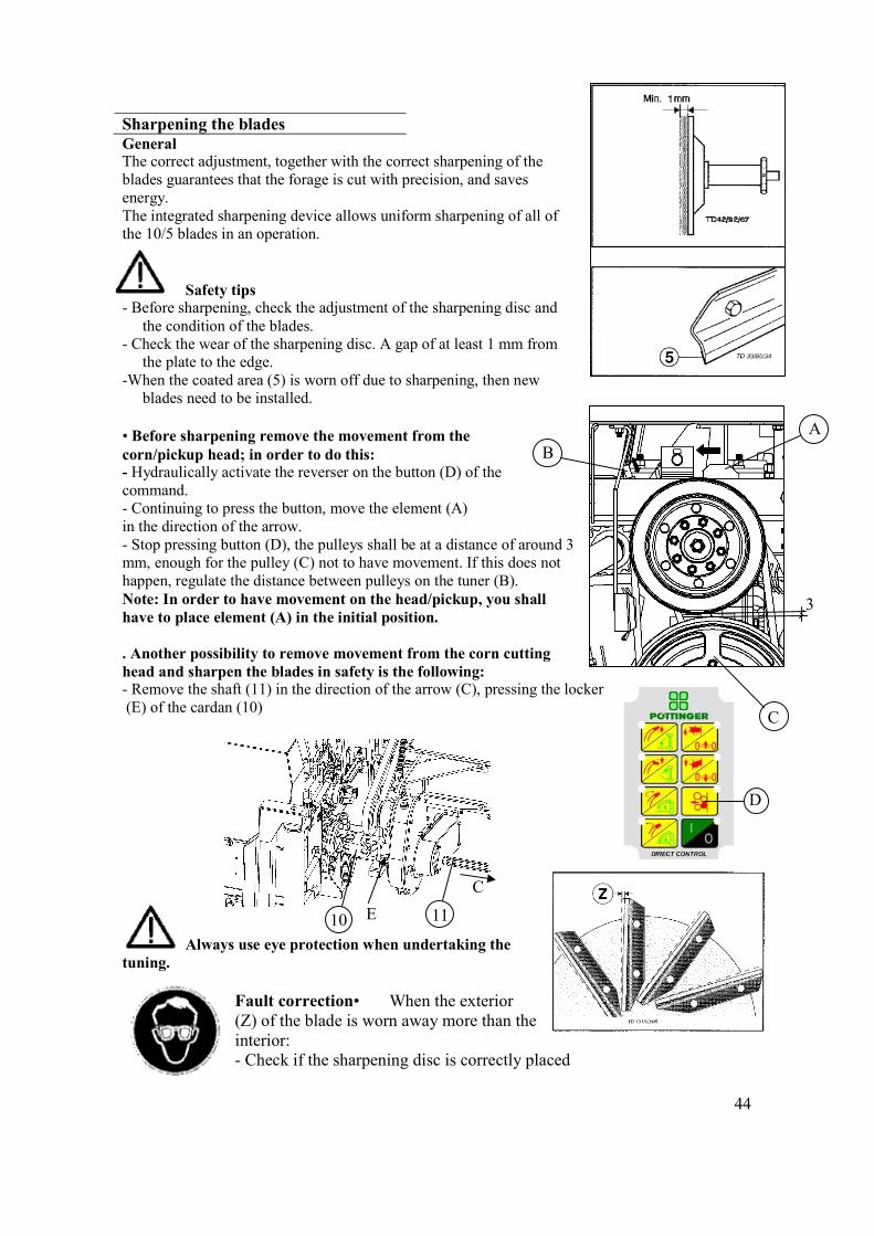
Sharpening the blades General The correct adjustment, together with the correct sharpening of the blades guarantees that the forage is cut with precision, and saves energy. The integrated sharpening device allows uniform sharpening of all of the 10/5 blades in an operation. Safety tips - Before sharpening, check the adjustment of the sharpening disc and
the condition of the blades. - Check the wear of the sharpening disc. A gap of at least 1 mm from
the plate to the edge. -When the coated area (5) is worn off due to sharpening, then new
blades need to be installed. • Before sharpening remove the movement from the corn/pickup head; in order to do this: - Hydraulically activate the reverser on the button (D) of the command. - Continuing to press the button, move the element (A) in the direction of the arrow. - Stop pressing button (D), the pulleys shall be at a distance of around 3 mm, enough for the pulley (C) not to have movement. If this does not happen, regulate the distance between pulleys on the tuner (B). Note: In order to have movement on the head/pickup, you shall have to place element (A) in the initial position. . Another possibility to remove movement from the corn cutting head and sharpen the blades in safety is the following: - Remove the shaft (11) in the direction of the arrow (C), pressing the locker (E) of the cardan (10)
Always use eye protection when undertaking the tuning.
Fault correction• When the exterior (Z) of the blade is worn away more than the interior: - Check if the sharpening disc is correctly placed
C
10 11 E
D
45
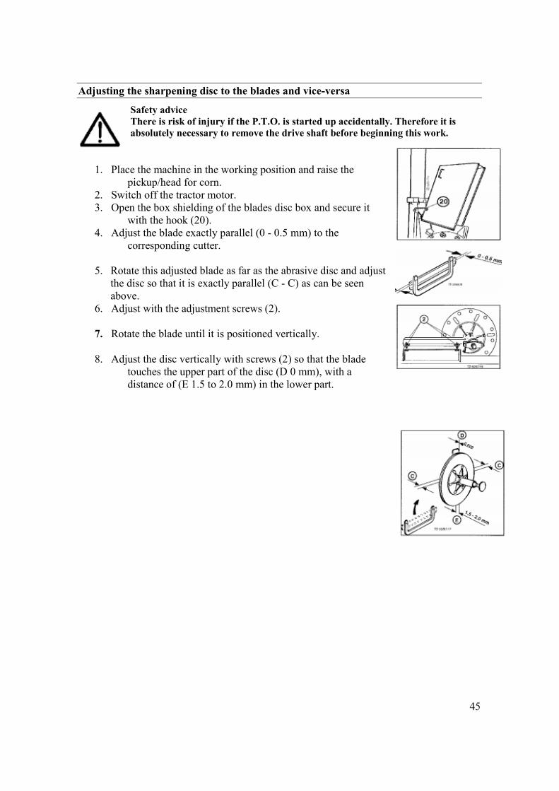
Adjusting the sharpening disc to the blades and vice-versa
Safety advice There is risk of injury if the P.T.O. is started up accidentally. Therefore it is absolutely necessary to remove the drive shaft before beginning this work.
1. Place the machine in the working position and raise the
pickup/head for corn. 2. Switch off the tractor motor. 3. Open the box shielding of the blades disc box and secure it
with the hook (20). 4. Adjust the blade exactly parallel (0 - 0.5 mm) to the
corresponding cutter.
5. Rotate this adjusted blade as far as the abrasive disc and adjust the disc so that it is exactly parallel (C - C) as can be seen above.
6. Adjust with the adjustment screws (2).
7. Rotate the blade until it is positioned vertically.
8. Adjust the disc vertically with screws (2) so that the blade touches the upper part of the disc (D 0 mm), with a distance of (E 1.5 to 2.0 mm) in the lower part.
46
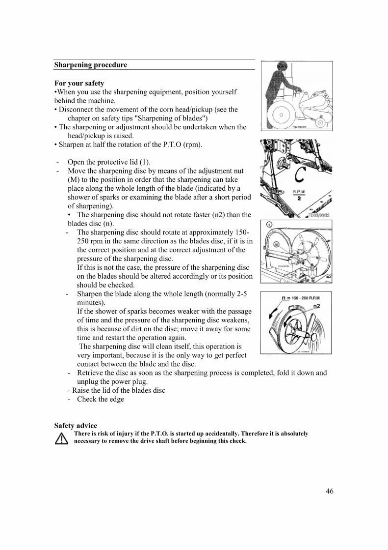
Sharpening procedure For your safety •When you use the sharpening equipment, position yourself behind the machine. • Disconnect the movement of the corn head/pickup (see the
chapter on safety tips "Sharpening of blades") • The sharpening or adjustment should be undertaken when the
head/pickup is raised. • Sharpen at half the rotation of the P.T.O (rpm). - Open the protective lid (1). - Move the sharpening disc by means of the adjustment nut
(M) to the position in order that the sharpening can take place along the whole length of the blade (indicated by a shower of sparks or examining the blade after a short period of sharpening). • The sharpening disc should not rotate faster (n2) than the blades disc (n).
- The sharpening disc should rotate at approximately 150-250 rpm in the same direction as the blades disc, if it is in the correct position and at the correct adjustment of the pressure of the sharpening disc. If this is not the case, the pressure of the sharpening disc on the blades should be altered accordingly or its position should be checked.
- Sharpen the blade along the whole length (normally 2-5 minutes). If the shower of sparks becomes weaker with the passage of time and the pressure of the sharpening disc weakens, this is because of dirt on the disc; move it away for some time and restart the operation again. The sharpening disc will clean itself, this operation is very important, because it is the only way to get perfect contact between the blade and the disc.
- Retrieve the disc as soon as the sharpening process is completed, fold it down and unplug the power plug.
- Raise the lid of the blades disc - Check the edge
Safety advice
There is risk of injury if the P.T.O. is started up accidentally. Therefore it is absolutely necessary to remove the drive shaft before beginning this check.
47
Adjusting the blades disc
Safety advice There is risk of injury if the P.T.O. is started up accidentally. Therefore it is absolutely necessary to remove the drive shaft
before beginning this work. • Open the lid
- Affix it to the tower with the hook (20). • Check the space between the blades and the cutting mouth.
- The gap should be 0-0.5 mm, if this does not happen:
• After pulling backwards and rotating the safety pin (22) of the adjustment nut (21), the latter should be blocked with the attached key (23).
• By rotating the blades disc in the opposite direction to the cut, the blade moves up against the counter-blade (24), check the gap (around 0.5 mm).
• Then, affix the adjustment nut (21) with the safety pin (22), remove the key (23) and keep it.
• Finally, rotate the blades disc a few times by hand. Attention! • For the integrated grain crusher, check the lateral gap of the crushers.
- The individual readjustment of each blade is only necessary if the range of the sharpening ring (25) has already been exhausted due to frequent adjustments in the cutting wheel (the sharpening rings are seated one against the other).
Attention! It is absolutely necessary to insert the closing bar (23) correctly and to remove it in accordance with the adjustment pressure.
Replacing the blades • Remove the worn out blades • Then pull and rotate the safety pin (22), affix the adjustment nut
(21) with the key (23) and rotate the blades disc 3 1/2 times (= 7 mm of adjustment) in the direction of the cutting.
• Then, affix the adjustment nut (21) with the safety pin (22), remove the key (23) and keep it.
• Screw on each blade securely and adjust each side edge of the cutting with the counter-blade, (0.5 mm) using the adjustment nuts (B).
• Finally, rotate the blades disc a few times by hand.
48
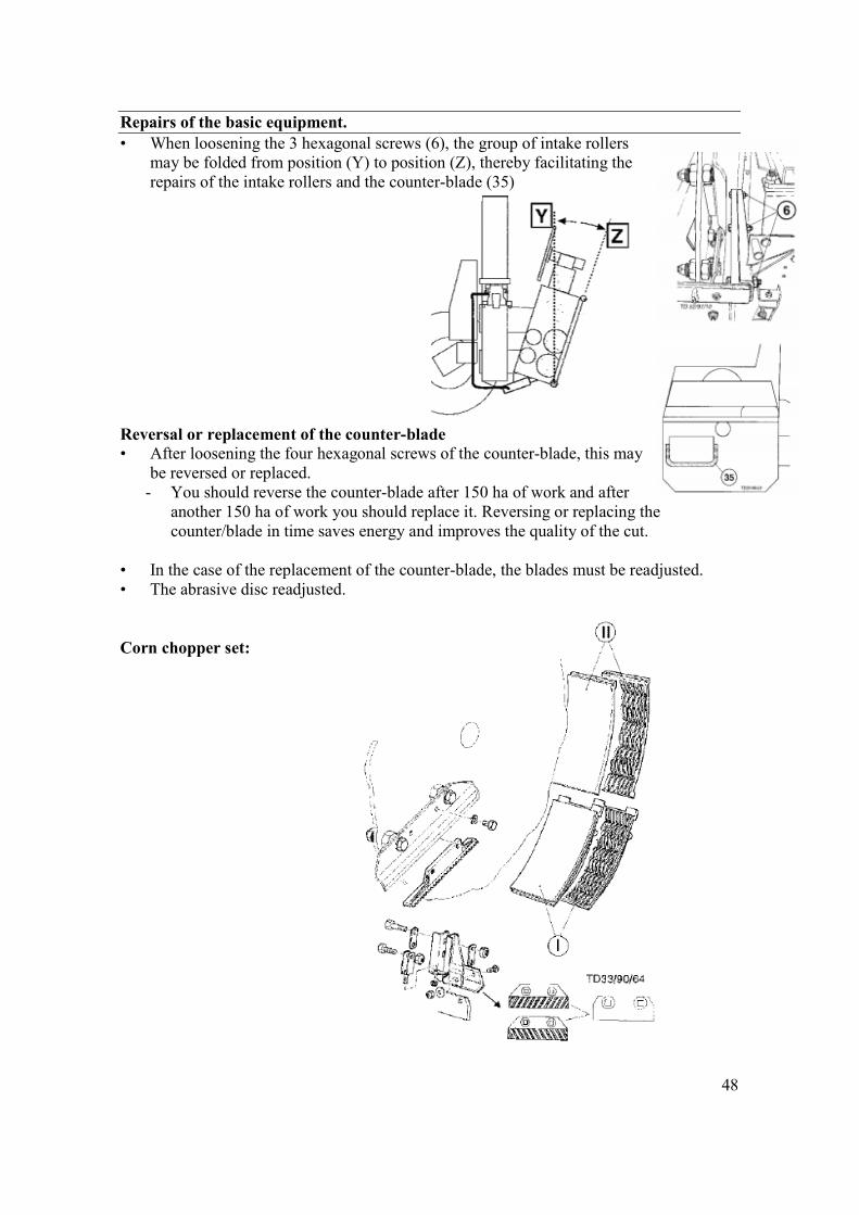
Repairs of the basic equipment. • When loosening the 3 hexagonal screws (6), the group of intake rollers
may be folded from position (Y) to position (Z), thereby facilitating the repairs of the intake rollers and the counter-blade (35)
Reversal or replacement of the counter-blade • After loosening the four hexagonal screws of the counter-blade, this may
be reversed or replaced. - You should reverse the counter-blade after 150 ha of work and after
another 150 ha of work you should replace it. Reversing or replacing the counter/blade in time saves energy and improves the quality of the cut.
• In the case of the replacement of the counter-blade, the blades must be readjusted. • The abrasive disc readjusted. Corn chopper set:
49
14
A
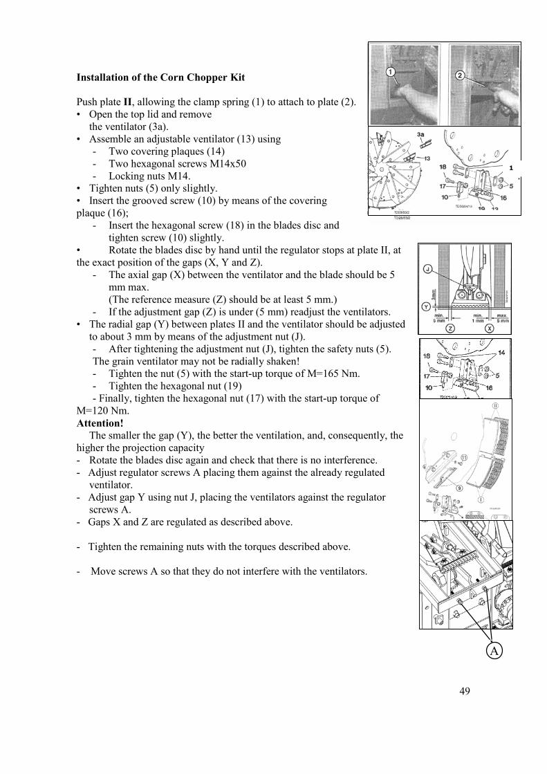
Installation of the Corn Chopper Kit Push plate II, allowing the clamp spring (1) to attach to plate (2). • Open the top lid and remove
the ventilator (3a). • Assemble an adjustable ventilator (13) using
- Two covering plaques (14) - Two hexagonal screws M14x50 - Locking nuts M14.
• Tighten nuts (5) only slightly. • Insert the grooved screw (10) by means of the covering plaque (16);
- Insert the hexagonal screw (18) in the blades disc and tighten screw (10) slightly.
• Rotate the blades disc by hand until the regulator stops at plate II, at the exact position of the gaps (X, Y and Z).
- The axial gap (X) between the ventilator and the blade should be 5 mm max.
(The reference measure (Z) should be at least 5 mm.) - If the adjustment gap (Z) is under (5 mm) readjust the ventilators.
• The radial gap (Y) between plates II and the ventilator should be adjusted to about 3 mm by means of the adjustment nut (J). - After tightening the adjustment nut (J), tighten the safety nuts (5). The grain ventilator may not be radially shaken! - Tighten the nut (5) with the start-up torque of M=165 Nm. - Tighten the hexagonal nut (19) - Finally, tighten the hexagonal nut (17) with the start-up torque of
M=120 Nm. Attention!
The smaller the gap (Y), the better the ventilation, and, consequently, the higher the projection capacity - Rotate the blades disc again and check that there is no interference. - Adjust regulator screws A placing them against the already regulated
ventilator. - Adjust gap Y using nut J, placing the ventilators against the regulator
screws A. - Gaps X and Z are regulated as described above. - Tighten the remaining nuts with the torques described above. - Move screws A so that they do not interfere with the ventilators.
50
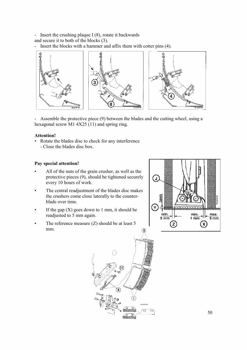
- Insert the crushing plaque I (8), rotate it backwards and secure it to both of the blocks (3). - Insert the blocks with a hammer and affix them with cotter pins (4). - Assemble the protective piece (9) between the blades and the cutting wheel, using a hexagonal screw M1 4X25 (11) and spring ring. Attention! • Rotate the blades disc to check for any interference - Close the blades disc box. Pay special attention!
• All of the nuts of the grain crusher, as well as the protective pieces (9), should be tightened securely every 10 hours of work.
• The central readjustment of the blades disc makes the crushers come close laterally to the counter-blade over time.
• If the gap (X) goes down to 1 mm, it should be readjusted to 5 mm again.
• The reference measure (Z) should be at least 5 mm.
51
Maintenance care to be taken into account.
General information Accurate care and correct maintenance will ensure constant readiness and a long useful life for the machine; especially recommended is the use of a good lubricant and compliance with the lubrication instructions. To check or once again fill the transmission oil, the machine should be levelled.
Attention! After each cleaning with a high-pressure machine Lubricate the machine in accordance with the lubrication scheme and do a short test.
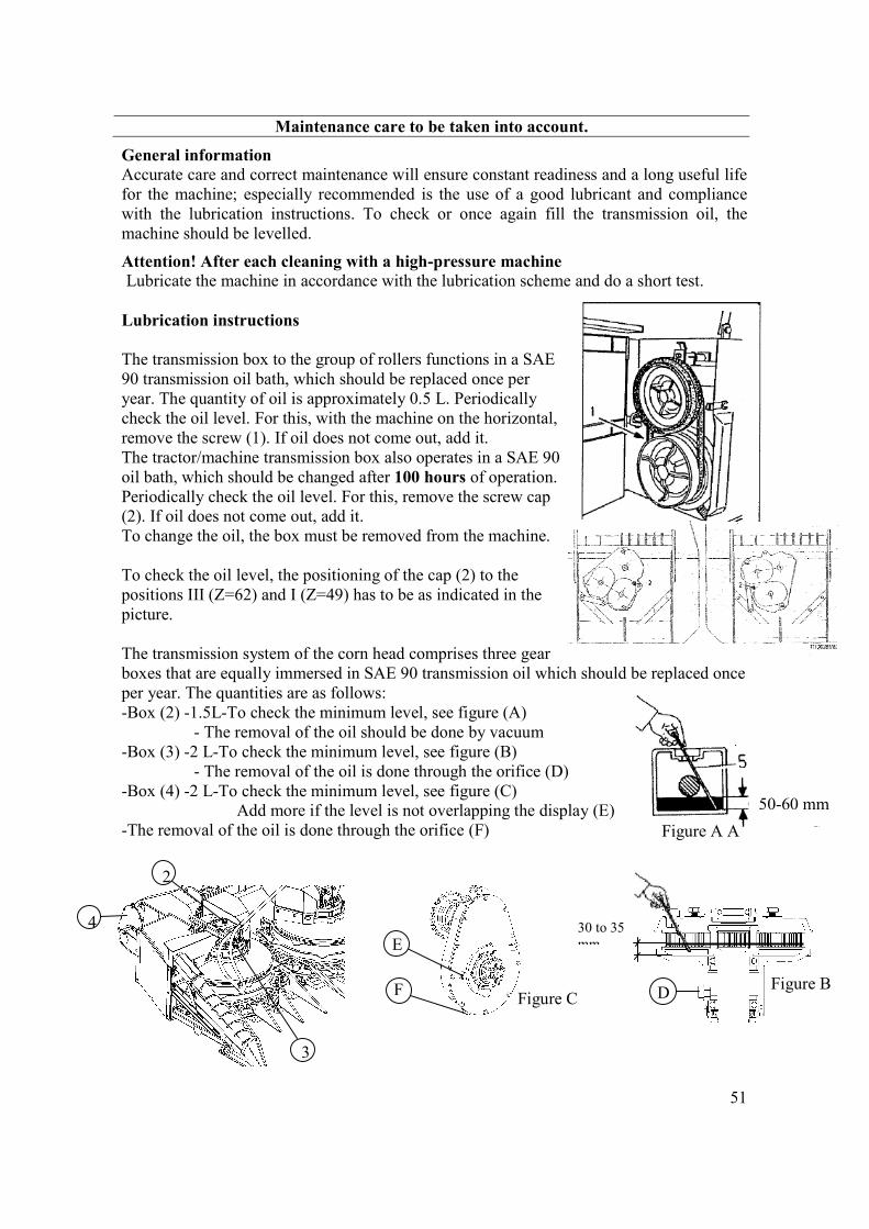
Lubrication instructions The transmission box to the group of rollers functions in a SAE 90 transmission oil bath, which should be replaced once per year. The quantity of oil is approximately 0.5 L. Periodically check the oil level. For this, with the machine on the horizontal, remove the screw (1). If oil does not come out, add it. The tractor/machine transmission box also operates in a SAE 90 oil bath, which should be changed after 100 hours of operation. Periodically check the oil level. For this, remove the screw cap (2). If oil does not come out, add it. To change the oil, the box must be removed from the machine. To check the oil level, the positioning of the cap (2) to the positions III (Z=62) and I (Z=49) has to be as indicated in the picture. The transmission system of the corn head comprises three gear boxes that are equally immersed in SAE 90 transmission oil which should be replaced once per year. The quantities are as follows: -Box (2) -1.5L-To check the minimum level, see figure (A) - The removal of the oil should be done by vacuum -Box (3) -2 L-To check the minimum level, see figure (B) - The removal of the oil is done through the orifice (D) -Box (4) -2 L-To check the minimum level, see figure (C) Add more if the level is not overlapping the display (E) -The removal of the oil is done through the orifice (F) 2
3
4
Figure B D
30 to 35 mm
Figure C F
E
50-60 mm
Figure A A
52
Winter Storage • The moving parts (group of rollers, blades disc, rotating collection drums, etc.), as
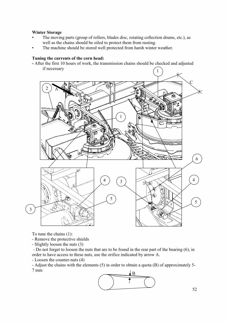
well as the chains should be oiled to protect them from rusting. • The machine should be stored well protected from harsh winter weather. Tuning the currents of the corn head: - After the first 10 hours of work, the transmission chains should be checked and adjusted
if necessary To tune the chains (1): - Remove the protective shields - Slightly loosen the nuts (3) - Do not forget to loosen the nuts that are to be found in the rear part of the bearing (6), in order to have access to these nuts, use the orifice indicated by arrow A. - Loosen the counter-nuts (4) - Adjust the chains with the elements (5) in order to obtain a quota (B) of approximately 5-7 mm
B
1
1
4
5 5
3
2
3 4
A
6
C
53
10
11
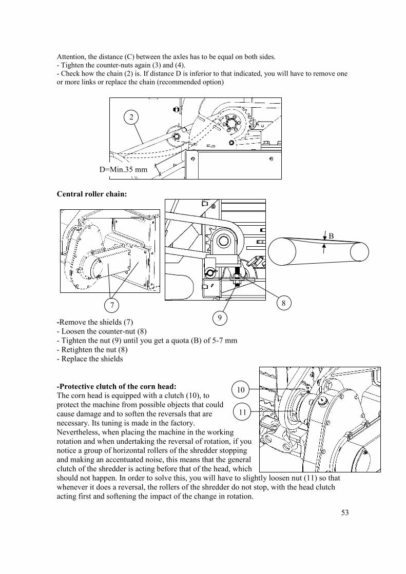
Attention, the distance (C) between the axles has to be equal on both sides. - Tighten the counter-nuts again (3) and (4). - Check how the chain (2) is. If distance D is inferior to that indicated, you will have to remove one or more links or replace the chain (recommended option) Central roller chain: -Remove the shields (7) - Loosen the counter-nut (8) - Tighten the nut (9) until you get a quota (B) of 5-7 mm - Retighten the nut (8) - Replace the shields -Protective clutch of the corn head: The corn head is equipped with a clutch (10), to protect the machine from possible objects that could cause damage and to soften the reversals that are necessary. Its tuning is made in the factory. Nevertheless, when placing the machine in the working rotation and when undertaking the reversal of rotation, if you notice a group of horizontal rollers of the shredder stopping and making an accentuated noise, this means that the general clutch of the shredder is acting before that of the head, which should not happen. In order to solve this, you will have to slightly loosen nut (11) so that whenever it does a reversal, the rollers of the shredder do not stop, with the head clutch acting first and softening the impact of the change in rotation.
2
D=Min.35 mm
B
9
8 7
54
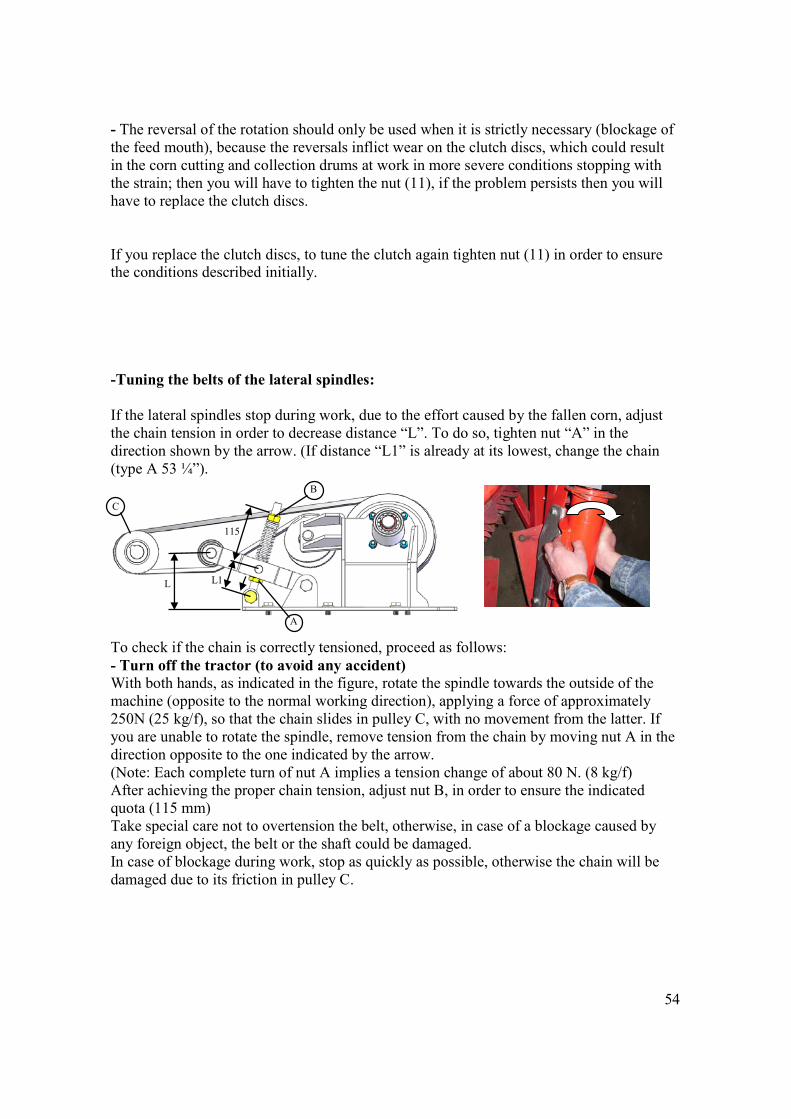
- The reversal of the rotation should only be used when it is strictly necessary (blockage of the feed mouth), because the reversals inflict wear on the clutch discs, which could result in the corn cutting and collection drums at work in more severe conditions stopping with the strain; then you will have to tighten the nut (11), if the problem persists then you will have to replace the clutch discs. If you replace the clutch discs, to tune the clutch again tighten nut (11) in order to ensure the conditions described initially. -Tuning the belts of the lateral spindles: If the lateral spindles stop during work, due to the effort caused by the fallen corn, adjust the chain tension in order to decrease distance “L”. To do so, tighten nut “A” in the direction shown by the arrow. (If distance “L1” is already at its lowest, change the chain (type A 53 ¼”). To check if the chain is correctly tensioned, proceed as follows: - Turn off the tractor (to avoid any accident) With both hands, as indicated in the figure, rotate the spindle towards the outside of the machine (opposite to the normal working direction), applying a force of approximately 250N (25 kg/f), so that the chain slides in pulley C, with no movement from the latter. If you are unable to rotate the spindle, remove tension from the chain by moving nut A in the direction opposite to the one indicated by the arrow. (Note: Each complete turn of nut A implies a tension change of about 80 N. (8 kg/f) After achieving the proper chain tension, adjust nut B, in order to ensure the indicated quota (115 mm) Take special care not to overtension the belt, otherwise, in case of a blockage caused by any foreign object, the belt or the shaft could be damaged. In case of blockage during work, stop as quickly as possible, otherwise the chain will be damaged due to its friction in pulley C.
115
L1 L
A
C
B
55
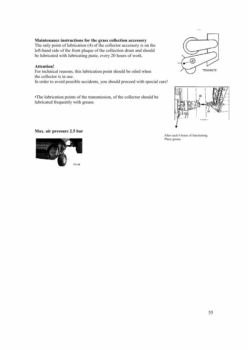
Maintenance instructions for the grass collection accessory The only point of lubrication (4) of the collector accessory is on the left-hand side of the front plaque of the collection drum and should be lubricated with lubricating paste, every 20 hours of work. Attention! For technical reasons, this lubrication point should be oiled when the collector is in use. In order to avoid possible accidents, you should proceed with special care! •The lubrication points of the transmission, of the collector should be lubricated frequently with grease.
Max. air pressure 2.5 bar After each 6 hours of functioning Place grease
56
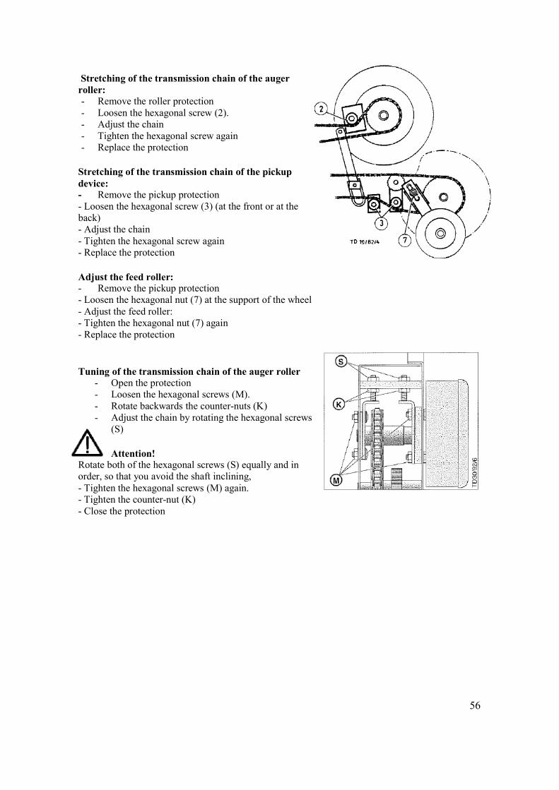
Stretching of the transmission chain of the auger roller: - Remove the roller protection - Loosen the hexagonal screw (2). - Adjust the chain - Tighten the hexagonal screw again - Replace the protection
Stretching of the transmission chain of the pickup device: - Remove the pickup protection - Loosen the hexagonal screw (3) (at the front or at the back) - Adjust the chain - Tighten the hexagonal screw again - Replace the protection Adjust the feed roller: - Remove the pickup protection - Loosen the hexagonal nut (7) at the support of the wheel - Adjust the feed roller: - Tighten the hexagonal nut (7) again - Replace the protection Tuning of the transmission chain of the auger roller
- Open the protection - Loosen the hexagonal screws (M). - Rotate backwards the counter-nuts (K) - Adjust the chain by rotating the hexagonal screws
(S) Attention! Rotate both of the hexagonal screws (S) equally and in order, so that you avoid the shaft inclining, - Tighten the hexagonal screws (M) again. - Tighten the counter-nut (K) - Close the protection

57
Lubrication: Automatic Lubrication of the Chain Function: Whenever the corn head or the grass pickup is elevated hydraulically, the pistons of the oil pump (P) are activated. This action causes a small quantity of lubricant to be transported each time to the individual lubrication points. This pump has 7 outlets available, 3 for the shredder machine and 4 for the pickup/corn head. Therefore, whenever you couple the grass pickup or the corn head, remember to connect the corresponding tubes (A). Attention: Whenever you uncouple the grass pickup or the corn head, remember to disconnect the corresponding (A) tubes, otherwise they could be damaged. Before use Check the oil level (OIL) in the recipient and fill it again if necessary. Please use only oil that is environmentally safe and biodegradable.
A
58
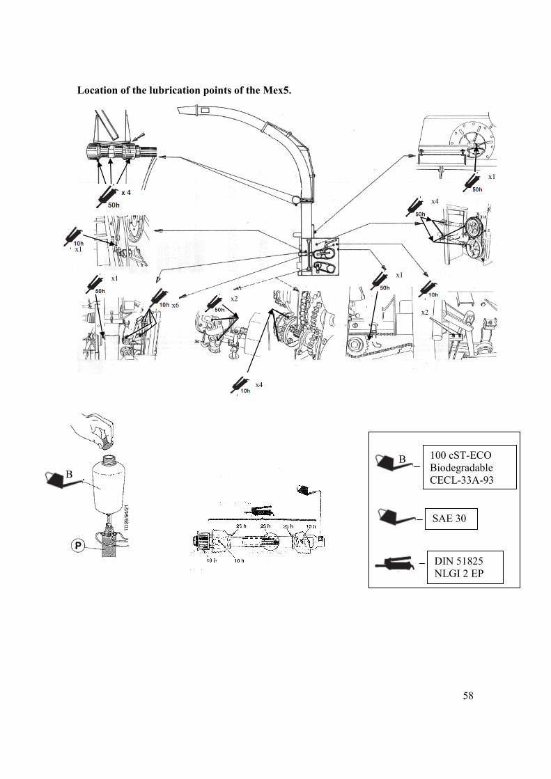
Location of the lubrication points of the Mex5.
x1
x6
x1
x1
x4
x2
x1
x2
x4
SAE 30
DIN 51825 NLGI 2 EP
B 100 cST-ECO Biodegradable CECL-33A-93B
59
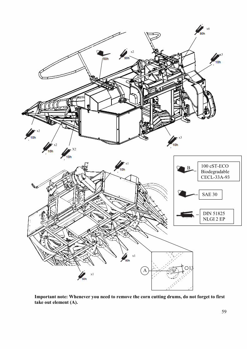
Important note: Whenever you need to remove the corn cutting drums, do not forget to first take out element (A).
SAE 30
DIN 51825 NLGI 2 EP
B 100 cST-ECO Biodegradable CECL-33A-93
A 13
x1
x1
x1
x6
x3
x3
x2
x2
x2
X2
60
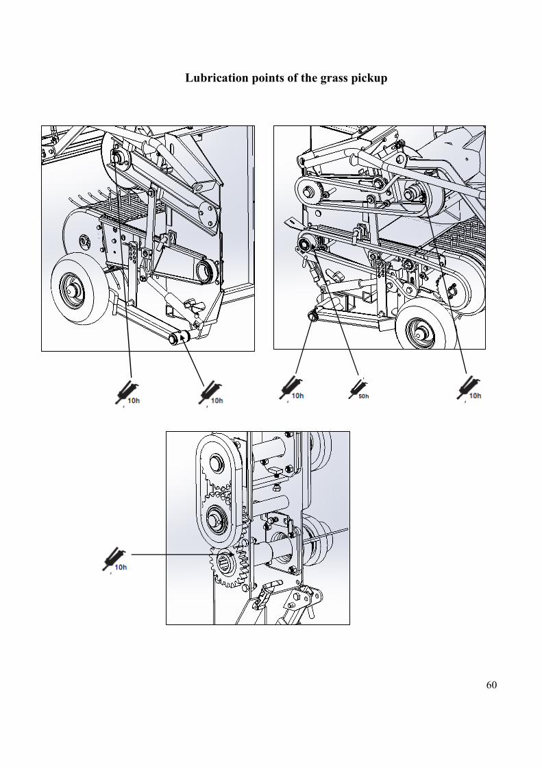
Lubrication points of the grass pickup

61
Breakdowns Before a breakdown may be repaired, disconnect the power plug and the tractor motor and wait for all of the
moving parts to be immobilised. Never try to resolve a breakdown with the machine in use. - Switch off the motor and remove the key. General
All machines will break down every now and then. The following information should help you to recognise the problems. You should always try to resolve the problem as soon as possible.
Breakdown 1. Noise of the beat during use: 2. Overheating of the gear box: 3. Heating of a cap:
Solution Adjust the tension of the chain. Check the level and the quantity of oil. Lubricate the machine in accordance with the lubrication plan.
Admission 4. The clutch of the admission roles acts: 5. The clutch of the admission roles acts just a little: 6. The corn is not collected in a clean form: 7. The admission does not function at full speed:
Blockage or foreign substance at the mouth of the entrance Replace the clutch or the springs Examine the level of the cut and the elements of the cut Check the tension of the belt in V.
Blades disc 8. The stems of the corn are not cut in a clean form and at
the desired height:
Adjust the blades disc to the counter-blade or sharpen the blades.
Ventilation 9. Very weak ventilation: 10. The ventilation tube blocks at start-up due to a fault in
reaching the necessary rotation speed:
The shovels are very worn, so replace them. Clean the blower tube.
Corn head 11. Blocked with foreign matter:
12. Blockage or blocking of the admission channel:
13. Pushes the corn forward without cutting it 14. Drums stop during work
15. The lower cutting discs stop and do not cut
16. The lateral spindles stopped
Put the machine functioning in reverse for a short space of time, wait for the moving parts to stop, remove the foreign matter. Check the functioning of the central roller Adjust the upper guide Check if the front nozzles are free of obstructions Adjust the clutch or replace the discs Replace the bearing rollers of the disc (piece no. 9 of set 21307008/9) Check the tensioner and adjust if necessary.
62
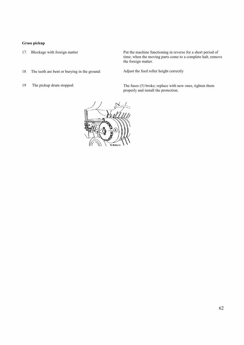
Grass pickup 17. Blockage with foreign matter 18 The teeth are bent or burying in the ground: 19 The pickup drum stopped:
Put the machine functioning in reverse for a short period of time; when the moving parts come to a complete halt, remove the foreign matter.
Adjust the feed roller height correctly The fuses (5) broke; replace with new ones, tighten them properly and install the protection.
63
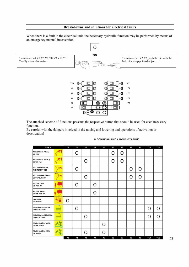
Breakdowns and solutions for electrical faults When there is a fault in the electrical unit, the necessary hydraulic function may be performed by means of an emergency manual intervention. The attached scheme of functions presents the respective button that should be used for each necessary function. Be careful with the dangers involved in the raising and lowering and operations of activation or deactivation!
To activate Y4;Y5;Y6;Y7;Y8;Y9;Y10;Y11 Totally rotate clockwise
To activate Y1;Y2;Y3, push the pin with the help of a sharp pointed object
64
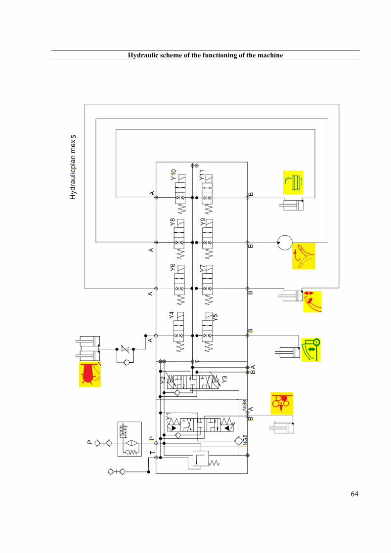
Hydraulic scheme of the functioning of the machine
5
65
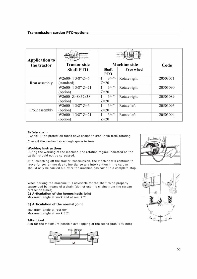
Transmission cardan PTO-options
Application to the tractor
Tractor side Shaft PTO
Machine side
Code
Shaft PTO
Free wheel
Rear assembly
W2600- 1 3/8”-Z=6 (standard)
1 3/4”-Z=20
Rotate right 20503071
W2600- 1 3/8”-Z=21 (option)
1 3/4”-Z=20
Rotate right 20503090
W2600- Z=8x32x38 (option)
1 3/4”-Z=20
Rotate right 20503089
Front assembly
W2600- 1 3/8”-Z=6 (option)
1 3/4”-Z=20
Rotate left 20503093
W2600- 1 3/8”-Z=21 (option)
1 3/4”-Z=20
Rotate left 20503094
Safety chain - Check if the protection tubes have chains to stop them from rotating.
Check if the cardan has enough space to turn. Working instructions During the working of the machine, the rotation regime indicated on the cardan should not be surpassed.
After switching off the tractor transmission, the machine will continue to move for some time due to inertia, so any intervention in the cardan should only be carried out after the machine has come to a complete stop. When parking the machine it is advisable for the shaft to be properly suspended by means of a chain (do not use the chains from the cardan protection tubes). 2) Articulation of the homocinetic joint Maximum angle at work and at rest 70º. 3) Articulation of the normal joint
Maximum angle at rest 90º. Maximum angle at work 35º. Attention! Aim for the maximum possible overlapping of the tubes (min. 150 mm)
Min. 150 mm
66
• Before putting the machine into movement, check if the safety latches of the cardan are properly placed
Maintenance
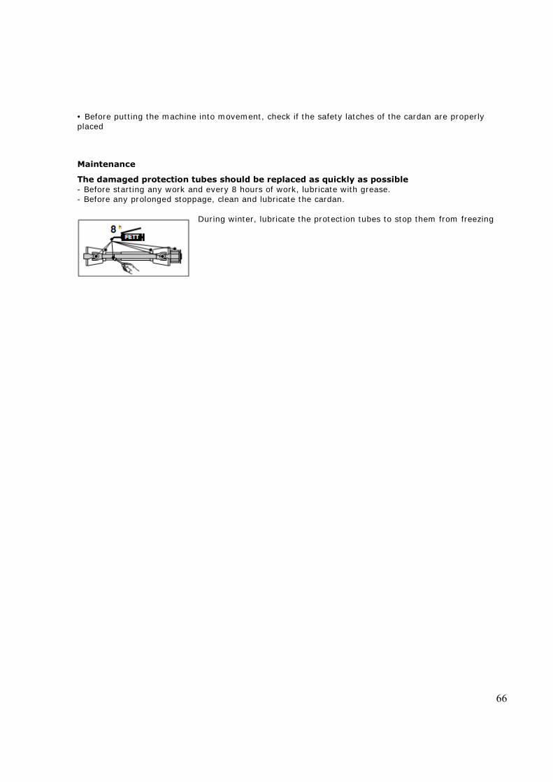
The damaged protection tubes should be replaced as quickly as possible - Before starting any work and every 8 hours of work, lubricate with grease. - Before any prolonged stoppage, clean and lubricate the cardan.
During winter, lubricate the protection tubes to stop them from freezing
A empresa PÖTTINGER Landtechnik GmbH esforçase continuamente por melhorar os seus produtos, adaptando-os à evolução técnica.
Por este motivo, reservamonos o direito de modificar as figuras e as descrições constantes no presente manual, sem incorrer na obrigação de modificar máquinas já fornecidas.As características técnicas, as dimensões e os pesos não são vinculativos.A reprodução ou a tradução do presente manual de instruções, seja ela total ou parcial, requer a autorização por escrito daPÖTTINGER Landtechnik GmbHA-4710 GrieskirchenTodos os direitos estão protegidos pela lei da prop-riedade intelectual.
Im Zuge der technischen Weiterentwicklung arbeitet die PÖTTINGER Landtechnik GmbH ständig an der Verbesserung ihrer
Produkte. Änderungen gegenüber den Abbildungen und Beschreibungen dieser Betriebsanleitung müssen wir uns darum vorbehalten, ein Anspruch auf Änderungen an bereits ausgelieferten Maschinen kann daraus nicht abgeleitet werden. Technische Angaben, Maße und Gewichte sind unverbindlich. Irrtümer vorbehalten. Nachdruck oder Übersetzung, auch auszugsweise, nur mit schriftlicher Genehmigung der PÖTTINGER Landtechnik GmbH A-4710 Grieskirchen.Alle Rechte nach dem Gesetz des Urheberrecht vorbehalten.
La société PÖTTINGER Landtechnik GmbH améliore constamment ses produits grâce au progrès technique.
C'est pourquoi nous nous réser-vons le droit de modifier descriptions et illustrations de cette notice d'utilisation, sans qu'on en puisse faire découler un droit à modifications sur des machines déjà livrées.Caractéristiques techniques, dimensions et poids sont sans engagement. Des erreurs sont possibles.Copie ou traduction, même d'extraits, seulement avec la permission écrite dePÖTTINGER Landtechnik GmbHA-4710 Grieskirchen.Tous droits réservés selon la réglementation des droits d'auteurs.
Following the policy of the PÖTTINGER Landtechnik GmbH to improve their products as technical developments continue,
PÖTTINGER reserve the right to make alterations which must not necessarily correspond to text and illustrations contai-ned in this publication, and without incurring obligation to alter any machines previously delivered.Technical data, dimensions and weights are given as an indication only. Responsibility for errors or omissions not accepted.Reproduction or translation of this publication, in whole or part, is not permitted without the written consent of thePÖTTINGER Landtechnik GmbHA-4710 Grieskirchen.All rights under the provision of the copyright Act are reserved.
PÖTTINGER Landtechnik GmbH werkt permanent aan de verbetering van hun producten in het kader van hun technische ontwikkelingen. Daarom moeten wij ons
veranderingen van de afbeeldingen en beschrijvingen van deze gebruiksaanwijzing voorbehouden, zonder dat daaruit een aanspraak op veranderingen van reeds geieverde machines kan worden afgeleid.Technische gegevens, maten en gewichten zijn niet bindend. Vergissingen voorbehouden.Nadruk of vertaling, ook gedeeltelijk, slechts met schriftelijke toestemming vanPÖTTINGER Landtechnik GmbHA-4710 Grieskirchen.Alle rechten naar de wet over het auteursrecht voor-behouden.
La empresa PÖTTINGER Landtechnik GmbH se esfuerza contínuamente en la mejora constante de sus productos, adaptándolos a la evolución técnica. Por ello
nos vemos obligados a reservarnos todos los derechos de cualquier modificación de los productos con relación a las ilustraciones y a los textos del presente manual, sin que por ello pueda ser deducido derecho alguno a la modificación de máquinas ya suministradas.Los datos técnicos, las medidas y los pesos se entienden sin compromiso alguno.La reproducción o la traducción del presente manual de instrucciones, aunque sea tan solo parcial, requiere de la autorización por escrito dePÖTTINGER Landtechnik GmbHA-4710 Grieskirchen.Todos los derechos están protegidos por la ley de la propiedad industrial.
La PÖTTINGER Landtechnik GmbH è costantemente al lavoro per migliorare i suoi prodotti mantenendoli aggiornati rispetto allo sviluppo della tecnica.
Per questo motivo siamo costretti a riservarci la facoltà di apportare eventuali modifiche alle illustrazioni e alle descrizioni di queste istruzioni per l’uso. Allo stesso tempo ciò non comporta il diritto di fare apportare modifiche a macchine già fornite.I dati tecnici, le misure e i pesi non sono impegnativi. Non rispondiamo di eventuali errori. Ristampa o traduzione, anche solo parziale, solo dietro consenso scritto dellaPÖTTINGER Landtechnik GmbHA-4710 Grieskirchen.Ci riserviamo tutti i diritti previsti dalla legge sul diritto d’autore.
GB
I
P
NL
D
E
F

PÖTTINGER Deutschland GmbHServicecenter LandsbergSpöttinger-Straße 24Postfach 1561D-86 899 LANDSBERG / LECHTelefon: Ersatzteildienst: +49 8191 9299 - 166 od. 169Kundendienst: +49 8191 9299 - 130 od. 231Telefax: +49 8191 59656e-Mail: [email protected]
PÖTTINGER Landtechnik GmbHA-4710 GrieskirchenTelefon: +43 7248 600-0Telefax: +43 7248 600-2513e-Mail: [email protected]: http://www.poettinger.at
PÖTTINGER Deutschland GmbHVerkaufs- und Servicecenter ReckeSteinbecker Strasse 15D-49509 ReckeTelefon: +49 5453 9114-0Telefax: +49 5453 9114-14e-Mail: [email protected]
PÖTTINGER France S.A.R.L.129 b, la ChapelleF-68650 Le BonhommeTél.: +33 (0) 3 89 47 28 30e-Mail: [email protected]