OPERATOR’S MANUAL - Northern LightsOPERATOR'S MANUAL for Models NL498K2 and NL498D2 INTRODUCTION...
27
O PERATOR’S M ANUAL O PERATOR’S M ANUAL Publication #ONL498-2 for Models: NL498K2 and NL498D2
Transcript of OPERATOR’S MANUAL - Northern LightsOPERATOR'S MANUAL for Models NL498K2 and NL498D2 INTRODUCTION...

OPERATOR’SMANUALOPERATOR’SMANUAL
Publication #ONL498-2 for Models:
NL498K2 and NL498D2

Diesel engine exhaust and some of its constituentsare known to the State of California to cause
cancer, birth defects, and other reproductive harm.
— CALIFORNIA —Proposition 65 Warning:
Northern Lights4420 14th Avenue N.W.Seattle, WA 98107Tel: (206) 789-3880Fax: (206) 782-5455
Copyright ©2006 Alaska Diesel Electric, Inc.All rights reserved. Northern Lights™, andthe Northern Lights logo are trademarks ofAlaska Diesel Electric, Inc.
Printed in U.S.A.PART NO.: ONL498-2 03/06

ONL498-2 03/06
3
Read this operator's manual thoroughly before starting to operate your equipment.This manual contains information you will need to run and service your new unit.
OPERATOR'S MANUALfor Models
NL498K2 and NL498D2
INTRODUCTION ................................................... 2Model Included ................................................. 2Model Number .................................................. 2Serial Numbers .................................................. 2
WARRANTY ........................................................... 3
SAFETY RULES .................................................... 3
COMPONENT LOCATIONIndustrial Generator ........................................... 4
CONTROL PANELSNorthern Lights Generator Sets ....................5 - 6
OPERATING PROCEDURESBreak-in Period ................................................. 7Before Starting .................................................. 7Starting .............................................................. 7Operating ........................................................... 7Stopping ............................................................ 7Shutdowns and Alarms...................................... 8Spare Parts ......................................................... 8
SERVICING SCHEDULE CHART .............. 9 - 10
SERVICINGLubrication - General ...................................... 11Checking Oil ................................................... 11Oil Changes ..................................................... 11Changing Oil Filter .......................................... 11Air Filter .......................................................... 11
V-Belts ............................................................ 12Valve Clearances ............................................. 12Retightening Cylinder Head Bolts .................. 13Fuels - General ................................................ 13Fuel Filters ....................................................... 13Bleeding the Fuel System ................................ 14Injector Service ....................................... 14 - 15Injection Pump ................................................ 15Cooling System - General ............................... 15Checking Coolant Level .................................. 15Cooling System Flushing ................................ 15Clean Radiator ................................................. 15Generator Ends ................................................ 16Electrical System - General ............................. 16Booster Batteries ............................................. 16Battery Care ..................................................... 16Winterizing / Out-of-Service ........................... 16
TROUBLESHOOTINGElectrical .......................................................... 17Engine...................................................... 18 - 20
WIRING DIAGRAMSAC Electrical ........................................... 21 - 22DC Electrical ........................................... 23 - 24
Proprietary InformationThis publication is the property of Alaska Diesel Electric, Inc.
It may not be reproduced in whole or in part without the written permission of Alaska Diesel Electric, Inc.
© Alaska Diesel Electric, Inc. All rights reserved. Litho U.S.A. Publication number ONL498-2 03/06
Table of Contents

ONL498-2 03/06
4
The servicing of generator sets presents uniqueproblems. In many cases, the generator sets cannotbe moved to a repair facility. Failures often occurin remote areas far from competent assistance;therefore, maintenance schedules must be adheredto more strictly. Failures begin with minor problemsthat are overlooked and become amplified when notcorrected during routine maintenance.
As operator, it is your obligation to learn about yourequipment and its proper maintenance. This is not acomprehensive technical service manual. Nor will itmake the reader into an expert mechanic. Its aim isto aid you in maintaining your unit properly.
Introduction
NL - Northern Lights industrial generator set Model number of engine blockCylinders Bore
4 98 mm
Serial Numbers
MODELS INCLUDED
This manual covers the operating instructions for:
NL498K2 and NL498D2 industrial generator sets.
Model Numbers
Model numbers give the unit's application, block model, aspiration, and RPM:
+
Unit Identification
Northern Lights industrial generatorset with a 498 engine and aPX-332K generator end, Tier II.
NL498K2
NL 498
=
Your set has three serial numbers: ➀ an engine number stampedon a plate attached to the valve cover, ➁ a generator end serialnumber, and ➂ a generator set serial number.
NOTE: Always use the generator set serial number when orderingparts or in correspondence. The generator set serial number plate isfound on the service side of the generator and resembles the drawingin Figure 1.
Figure 1: Generator set serial number plate.
K2 - Taiyo Generator EndD2 - Stamford Generator End
K2 & D2
+
Northern Lights industrial generator set witha 498 engine and a UCI224C16 generator end,Tier II, 4 valve.
NL498D2 =
Northern Lights4420- 14th Ave. NWSeattle, WA 98107

ONL498-2 03/06
5
A warranty registration certificate is suppliedwith your set. It entitles the original purchaser ofour equipment to a warranty covering materialor assembly faults. The extent of coverage isdescribed in the Limited Warranty Statement. Werecommend that you study the statement carefully.
NOTE: If the warranty is to apply, the servicinginstructions outlined in this manual must befollowed. If further information is needed, pleasecontact an authorized dealer or the factory.
CAUTION: Accident reports show that careless use of engines causes a high percentage of accidents.You can avoid accidents by observing these safety rules. Study these rules carefully and enforce them on the job.
• Use caution in handling fuel. Never refuel a hotor running engine. Do not smoke while fillingfuel tank or servicing fuel system.
• Keep your hands, feet, hair and clothing awayfrom power-driven parts.
• Check for any loose electrical connections orfaulty wiring.
• Engines should be operated only byknowledgeable, qualified personnel.
• Look completely around engine to make surethat everything is clear before starting.
• Do not operate an engine that isn't in properworking order. If an unsafe operating condition isnoted, tag the set and control panel so others willalso know about the problem.
• Provide first aid kits.
• Never leave engine without proper security.
• Turn the coolant tank cap slowly to relievepressure before removing. Add coolant onlywhen the engine is stopped and cool.
• Mount a fire extinguisher near engine.
• Always disconnect the battery ground strapbefore making adjustments.
• Operate engines in properly ventilated areas.
• Keep trash and other objects away from engine.
• Escaping fluids under pressure can penetrateyour skin. Use a piece of cardboard or wood,not your hands, to search for leaks.
• Avoid wearing loose clothing without a beltwhen working around engines.
• Do not oil or grease engine while it is running.
Safety Rules
Warranty
CAUTION: This symbol is used throughoutthis book to alert you to possible danger areas.Please take special notice of these sections.
CALIFORNIAProposition 65 Warning:
Diesel engine exhaust and some of its constituentsare known to the State of California to cause
cancer, birth defects, and other reproductive harm.
ONL498-2 03/06
6
1. Control Panel
2. Generator Junction Box
3. DC Circuit Breaker
4. AVR Fuse
5. Air Cleaner
6. Exhaust Elbow
7. Muffler
8. Secondary Fuel Filter
9. Rocker Arm Cover
10. Fuel Injection Pump
11. Lube Oil Fill
12. Radiator Shroud
13. Lube Oil Filter
14. Fuel Return Manifold
15. Lube Oil Dipstick
16. Primary Fuel Filter
17. Alternator
18. Exhaust Manifold
19. Oil Pan
20. Flywheel Housing
21. Starter
Industrial Generator Component Locations
Figure 2A & B: NL498D2
2 3 4
5
1316
6
16
13
17 18
1
9 1110 12
1415
7
21
20
19
87

ONL498-2 03/06
7
Figure 3-B: Series 3 Generator Control Panel
Control Panels
Figure 3-A: Series 1-B Generator Control Panel
1. SHUTDOWN BYPASS-PREHEAT SWITCH
There are two functions built into this switch:preheating the engine and bypassing the engine safetyshutdown circuit, enabling a quicker start. Hold theswitch in the ON position for approximately 10 to 20seconds before starting a cold engine. Holding theswitch ON for too long can burn out the glow plugs.NOTE: Three position Engine Control switches must bein the RUN position during preheating. Preheat switchmust be held in ON position during starting.
2. ENGINE CONTROL SWITCH
To start the engine, hold this switch in the STARTposition until the engine is running.
After the engine starts, release the switch and it willreturn to RUN position. To stop the engine, hold theswitch in the STOP position.NOTE: The rocker switch is used on Series 1 panelsonly, and has a light that glows when the set is running.
3. HOUR METER
Keeps track of engine running time.
4. OIL PRESSURE GAUGE
Shows the oil pressure in the engine lubricating system.
5. WATER TEMPERATURE GAUGE
Registers the temperature of the cooling water.
6. D.C. VOLTMETER OR AMMETER
When the engine is stopped, the voltmeter indicates thecondition of the battery. When the engine is running, thevoltmeter indicates the voltage output of the alternator.

ONL498-2 03/06
8
Control Panels
Figure 4: Series 7.1 through Series 7.6 GeneratorControl Panels.
1. SHUTDOWN BYPASS SWITCH
Manual Start Panels(S-7.1 and S-7.3)
There are two functions built into this switch:preheating the engine and bypassing the engine safetyshutdown circuit, enabling a quicker start. Hold theswitch in the ON position for approximately 10 to 20seconds before starting a cold engine. Holding theswitch ON for too long can burn out the glow plugs.NOTE: Three position Engine Control switches must bein the RUN position during preheating. Preheat switchmust be held in ON position during starting.
Auto Start Panels(S-7.2, S-7.4, S-7.5, and S-7.6)
When the switch is placed in the AUTO STARTposition, the unit will automatically start when there isa drop in utility power.
2. OIL PRESSURE GAUGEShows the oil pressure in the engine lubricating system.
3. HOUR METERKeeps track of engine running time.
4. ENGINE TEMPERATURE GAUGERegisters the temperature of the coolant.
5. D.C. VOLTMETERWhen the engine is running, the voltmeter indicates thevoltage output of the alternator.
6. STATUS INDICATOR PANELEngine monitoring alarms and lamps for monitoringengine functions.
7. ALARM LAMP TEST AND RESET BUTTONPress UP to test the indicator lights and press DOWNto reset the alarm.
8. A.C. VOLTAGE ADJUSTMENT RHEOSTATVoltage has been set at the factory and should only beadjusted by factory-trained personnel.
9. AMMETER SELECTOR SWITCHUsed to check each phase for load condition.NOTE: Always leave this switch in the ON positionwhile the unit is running.
10. FREQUENCY METER (HERTZ)The frequency meter indicates alternator currentfrequency: 60 Hz (1200 or 1800 RPM), or 50 Hz (1500RPM).
11. A.C. VOLTMETERShows the generator output voltage.
12. A.C. AMMETERShows the generator load on each phase. The phase isselected with the Ammeter Selector switch (Item 9).

ONL498-2 03/06
9
BREAK-IN PERIOD
1. The first 100 hours on a new or reconditionedengine are critical to its life and performance.
2. Constantly check the engine temperature and oilpressure gauges.
3. Oil consumption is greater during break-in aspiston rings take time to seat.
4. Break-In Oil Changes: Change engine oil andfilter at 50 hours. Change oil and filter again at100 hours (consult Lubricants section for oilrecommendation), then every 250 hours.
5. Retighten head bolts at 50 hours.
Operating Instructions:Maintain at least a 75% load on your generatorset for the first 100 hours. If this is not possible,maintain no less than a 50% load to ensure properseating of the piston rings. Vary the load to helpseat the rings.
BEFORE STARTING
1. Check the water level by removing the pressurecap from the radiator. In order to give the coolingwater an opportunity to expand, the level should beabout 1 in. (2.5 cm) below the filler cap sealingsurface when the engine is cold.
CAUTION: Use protective clothing and openthe filler cap carefully when the engine is warmto prevent burns.
2. Check the oil level in the crankcase with thedipstick. The oil level must be between high and lowmarks on the stick. Never allow the level to gobelow this area. Always add the same viscosity of oilas is already in the crankcase.
3. Check the fuel tank level and open any fuel valveson the tank and at the secondary fuel filter.
4. Turn on any optional battery switch that may havebeen installed.
STARTING
1. Hold the Shutdown Bypass-Preheat switch in theON position for 10 to 20 seconds before starting acold engine. Holding the switch too long can burnout the heater elements. This step is not necessary ifthe engine is already warm.
2. While holding the Shutdown Bypass-Preheat switchin the ON position, push the Engine Control switchto the START position.
3. As soon as the engine starts, release both switches.Do not crank the starter for more than 20 secondsconsecutively. If the engine fails to start with thefirst attempt, be sure that it has stopped completelybefore re-engaging.
OPERATING
1. Units with Series 3 and Series 7 Control Panels:check gauges often. Oil pressure must be above 15PSI. The D.C. voltmeter should read between 11 and15 volts at 80°F (25°C) ambient temperature. Thewater temperature gauge must be below 200°F(94°C). Check the A.C. voltage and frequencymeters (Series 7 panel). If the gauges deviate fromnormal levels, shut down the generator set andinvestigate.
2. Let the unit run unloaded for a three to five minutewarm-up period.
3. Add electrical load.
STOPPING
1. Remove electrical load from the generator set.2. Run the engine for a three to five minute cool-down
period.3. Move the Engine Control switch to the STOP
position until the engine stops completely.4. Shut off fuel valve at the tank.
Operating Procedures
ONL498-2 03/06
10
SHUTDOWNS AND ALARMS
1. Your unit is fitted with a system to protect it fromhigh water temperature or low oil pressure.a. Generator sets have shutdown systems to stop the
engine. They have no warning horns.b. Other alarms and shutdowns are available as
optional equipment.NOTE: If your unit is equipped with optionalshutdowns and alarms, do not rely on yourwarning or shutdown system to the exclusion ofcareful gauge monitoring. Watching your gaugescan prevent damage to the unit and dangerouspower losses.
2. Do the following when your warning or shutdownsystem is activated:Depress the shutdown bypass switch and check thetemperature gauge. If above 230°F (110°C), use theTrouble Shooting Guide on page 19 toisolate the cause of the overheat.
CAUTION: Do not remove the water fillcap of an overheated engine. Escaping hightemperature steam can cause severe burns. Allowthe engine to cool and then remove the capslowly using protective clothing.
c. Make repairs and restart after the temperaturegauge registers below 210°F (99°C).
d. Watch the temperature gauge regularly andturn off the unit if the temperature rises above220°F (105°C). Repeat troubleshooting.
3. If shutdown is activated and the temperature gaugeshows temperature within normal temperature range:a. Check the engine crankcase oil level.b. If the oil level is low, fill with recommended
lubricating oil and restart. Watch the oil pressuregauge carefully and shut off the engine if it doesnot show a normal reading (20-60 PSI) after afew seconds of operation.
c. If the oil level is normal, DO NOT restart theengine. Call your dealer for assistance.
SPARE PARTS
1. ADE recommends that you keep the following spareparts on hand for field service. The parts areavailable from your local Northern Lights dealer.a. Primary and secondary fuel filter elementsb. Oil filtersc. Air filter elementsd. Alternator belte. Thermostat and gasketsf. Heater elementg. Injector and washer
2. If your set is operating a long distance from aservicing dealer, add the following:a. Complete set of injectorsb. Fuel lift pump
Operating Procedures

ONL498-2 03/06
11
SERVICE 50 250 500 1000 2000POINT PAGE OPERATION DAILY Hours Hours Hours Hours Hours
ENGINE:SP1 11 Check oil level �
SP2 11 Change engine oil 1) 5) �
SP3 11 Change lube oil filters 1) 5) �
SP4 11 Check air cleaner, replace element 1) 4) � �
SP5 12 Check V-belt tension 1) � �
SP6&7 12 Check valve clearances, retighten cyl.head bolts 4) 5) �
FUEL SYSTEM:SP8 13 Check primary filter 2) �
SP9 13 Change primary filter element 2) 3) �
SP10 13 Change secondary fuel filter 1) 3) �
SP11 14 Bleed the fuel system 3) �
SP12 14 - 15 Check injectors 1) 7) �
SP20 Check fuel injection nozzle pressure 7) �
SP13 15 Check fuel injection pump 7) �
COOLING SYSTEM:SP14 15 Check cooling water level �
SP15 15 Check and flush cooling system �
SP16 15 Check and clean radiator fins �
ELECTRICAL SYSTEM:SP17 16 Check electrolyte level in batteries 1) 4) �
SP18 16 Check condition of batteries with hydrometer 1) �
OUT OF SERVICE:SP19 16 Winterizing or out-of-service 3)
The Servicing Schedule Chart below shows the service schedule required for proper maintenance of your generator set.More detailed coverage of each Service Point (SP) is listed on the page noted in the ‘page’ column.
DAILY:SP1 Check oil level in engineSP4 Check air cleaner dust trap, replace element @250 hrs. or
when neededSP8 Check primary fuel filterSP14 Check cooling water level
AFTER FIRST 50 HOURS:SP2/3 Change engine oil and filterSP5 Check V-belt tensionSP6 Retighten cylinder head bolts
EVERY 50 HOURS:SP5 Check V-belt tensionSP11 Bleed the fuel systemSP17 Check electrolyte in batteries
EVERY 250 HOURS:SP2/3 Change engine oil and filterSP5 Check V-belt tensionSP9 Change primary fuel filter elementSP10 Change secondary fuel filterSP11 Bleed the fuel systemSP16 Check and clean radiator
EVERY 500 HOURS:SP12 Check injectorsSP18 Check state of charge of batteries
EVERY 1000 HOURS: SP7 Check valve clearances SP20 Check fuel injection nozzle pressure
EVERY 2000 HOURS:SP13 Check fuel injection pumpSP15 Check and flush cooling system
1) Perform all maintenance once a year even if hour level has not been reached.2) Consult manufacturer's maintenance schedule, note on chart.3) Whenever necessary.4) More often if necessary.5) After first 50 hours.
6) Adjust at first 100 hours.7) For EPA emission standards fuel nozzle needs to be
cleaned every 1500 hours, the fuel nozzle and fuel pumpneed to be cleaned, adjusted, or repaired every 3000hours, and the quality guarantee for these parts is 3000hours or 5 years.
Servicing Schedule Chart

ONL498-2 03/06
12
ServicePoint HOURS/DATE
50 HOURS
SP5 Check V-belt tension
SP17 Check electrolytein batteries
250 HOURS
SP2 Change engine oil
SP3 Change lubricating oil filters
SP4 Check air cleaner
SP9 Change primary filter element
SP10 Change secondary fuel filter
SP16 Check and clean radiator
500 HOURS
SP12 Check injectors
SP18 Check condition of batteries with hydrometer
1000 HOURS
SP7 Check valve clearances
SP20 Check fuel injection nozzle pressure
2000 HOURS
SP13 Check fuel injection pump
SP15 Check and flush cooling system
Service Notes:
Service Record
OPERATION

ONL498-2 03/06
13
Servicing
LUBRICATION - GENERAL
1. Use only clean, high quality lubricants stored inclean containers in a protected area.
2. These lubricants are acceptable:a. API Service CD/CF single viscosity oils.b. SAE viscocity 10W-30 or 15W-40 oils.
3. Use the proper weight oil for your average operationtemperature.
Figure 5: Lube Oils
4. Some increase in oil consumption may be expectedwhen SAE 5W and SAE 5-20W oils are used. Checkoil level frequently, and do not mix different types ofoil.
5. Never put additives or flushing oil in crankcase.
SP1. CHECKING OIL LEVEL
1. Check the oil level in the crankcase with the dipstickdaily. The oil level must be between the high andlow marks on the stick. Fill with the recommendedoil, and fill only to the high mark on the dipstick.Follow the lubrication recommendations above.
SP2. OIL CHANGES
1. The set is delivered with special break-in oil.Change the engine oil and oil filter after 50 hoursof operation. Use Service CC 30 weight oil duringthe first 100 hours.
2. Change the oil and filter again at 100 hours using theoil recommended in the above diagram. After this,change oil and filter every 250 hours.
3. During intermittent cold weather operation, change oilevery 100 hours or six weeks, whichever comes first.
Air Single Multi-Temperature Viscosity Viscosity
Above 32°F SAE 30W SAE 15-40W(0°C)
-10 to 32°F SAE 10W SAE 10-30W(-23 to 0°C)
Below -10°F SAE 5W SAE 5-20W(-23°C)
4. Change oil at any seasonal change in temperaturewhen a new viscosity of oil is required.
5. Change oil when engine is warm but not hot.6. Dispose of waste oil in an approved manner.7. Never use a flushing oil.8. Loosen plug in oil pan and drain oil into basin.9. Refill engine with recommended oil.10. Engine capacity with new oil filter is:
498 – 11.1 quarts (10.5 liters)
SP3. CHANGING LUBE OIL FILTER
1. Change the lube oil filter every 250 hours.2. Use a filter wrench to remove old filter. Dispose of
filter in approved manner.3. Make sure the gasket from the old filter is removed
and discarded. Clean mount face.4. Spread a thin film of engine oil on the rubber gasket
on the new filter and screw it on nipple until gasketmeets the sealing surface.
5. Using hands only – no wrench – tighten filterone-half turn farther. Overtightening can dodamage to filter housing.
6. Fill engine with recommended oil. Start engine andcheck for leakage. Stop engine, wait 3 minutes, andcheck oil level. Add additional oil if necessary.
7. Oil filter part number is: #24-07301.
SP4. AIR CLEANER
1. Check dust trap on bottom of air cleaner daily.Squeezing the lips of the rubber cap allows dirt tofall out.
2. Visually inspect air cleaner every 250 hours. Industy conditions, check more often.
3. An element cannot be cleaned. Replace dirtyelements when necessary. Part numbers are:
#24-28503 Outer #24-28504 Inner
NOTE: Make absolutely sure no impurities enterthe engine while changing the element, and do notrun the engine with the air cleaner removed.

ONL498-2 03/06
14
SP5. V-BELTS
1. Check the tension and wear on the V-belt afterevery 50 hours.
2. Use your thumb to press on the belt at the midpointbetween the crankshaft and alternator pulleys. Thetension is correct if the belt can be depressed about10-14 mm at point A, 7-10 mm at point B, and 9 to13 mm at point C for a belt used on a running enginefor more than 5 minutes (Fig. 6).
Figure 6: Alternator Drive Belt (V-belt) Adjustment
3. To adjust the belt tension, loosen bolt in thetensioning arm and move the alternator to tighten thebelt. If the belt has to be replaced, adjust it and thenrun the engine for 5 minutes and re-adjust if needed.
SP7. VALVE CLEARANCES
1. Adjust valve clearance every 1000 hours or once ayear.
2. Valve adjustments should be done when the engineis cold and NOT running.
3. Remove the rocker arm cover.4. Turn the crankshaft clockwise (as seen from the
radiator side) and bring the piston of the No. 1cylinder to top dead center, the position where theintake and exhaust valves are both closed. Also, seethat the crankshaft pulley top mark is positioned atzero on the timing scale.
5. To adjust, insert a thickness gauge in between therocker arm and valve bridge and record the valveclearance. Then loosen the lock nut and adjustingscrew of the rocker arm. Be careful that excessivetension is not applied to the valve bridge by fixing itwith a wrench so that the bridge does not rotate anda valve will not lean. (Figures 7 and 8).Clearance on intake and exhaust valves should be0.006 - .01 in. (0.15 - 0.25 mm).
Servicing
Figure 7: Valve Adjustment
Figure 8: Valve Clearance, 4 valve
6. Then turn the crankshaft 1800 and makeadjustments for the No. 3 cylinder. Then No. 4 andNo. 2 cylinders in that order. The first cylinder tobe adjusted does not have to be the No. 1 cylinder -just select and adjust the cylinder where the pistonis nearest to the top dead center after turning. Thenmake adjustments for the other cylinders in theorder of ignition by turning the crankshaft 1800 eachtime.
Cylinder 1 2 3 4
Valve Intake Exh. Intake Exh. Intake Exh. Intake Exh.
No. 1Compres.TDCNo. 4Compres.TDC
Ignition Order of 4 cylinder engines: 1 - 3 - 4 - 2Set the No. 1 cylinder to the compression TDC and adjust theclearance of the mark of the above table. Then turn theflywheel once and adjust the clearance of the mark.
1stTime
2ndTime
When adjusting the 4 valve cylinder head, push thebridge head so that a valve bridge and two valve stemheads contact uniformly and adjust the adjusting boltso that the gap of the valve stem head becomes 0.Tighten a locknut after the valve bridge is fixed with awrench. Apply oil to the contact surface betweenadjusting screw and push rod.

ONL498-2 03/06
15
Figure 9: Cylinder Head Bolt Torque Sequence
Servicing
Retightening Cylinder Head Bolts1. Tighten bolts when the engine is cold.2. Loosen the nuts and remove rocker arm cover.3. Tighten head bolts with a torque wrench in the order
shown in figure 9. Tighten bolts evenly in 2 or 3passes, ending at the specified torque in final pass.
4. Replace rocker arm cover.
Tightening Torque specifications:First Step: 49.0 ~ 58.8 N•m (5.0 ~ 6.0 kgf•m)Second Step: 103.1 ~ 112.9 N•m (10.5 ~ 11.5 kgf•m)
FUELS - GENERAL
1. Use only clean, high quality fuels of the followingspecifications, as defined by ASTM designationD975 for diesel fuels:a. Use grade no. 2 diesel at ambient temperatures
above freezing 32°F (0°C).b. Use grade no. 1 at ambient temperatures below
freezing and for all temperatures at an altitude ofabove 5,500 ft. (1500 meters).
c. International fuel specifications:ISO-8217-DMABS 2869 Part 1 Class A1BS 2869 Part 2 Class A2
2. Use fuel having less that 1% sulphur (preferably lessthan 0.5%).
3. The cetane number should be a minimum of 45.4. DO NOT use these unsuitable grades of fuel:
a. Domestic heating oils, all types.b. Class B engine.c. Class D domestic fuels.
d. Class E, F, G or H industrial or marine fuels.e. ASTM-D975-60T No. 4-D and higher number
fuels.5. Storing fuel:
a. Keep dirt, scale, water, and other foreign matterout of fuel.
b. Avoid storing fuel for long periods of time.c. Fill the fuel tank at the end of each day’s
operation. This will reduce condensation.
SP8-10. FUEL FILTERS
1. Your generator set should have a primary fuel filterinstalled. We recommend the Northern Lights brandof fuel filter-water separators.a. Check the primary fuel filter daily as
recommended by the filter manufacturer.Empty the collection bowl as necessary.
b. Change the element as often as necessary orevery 250 hours.
c. If the bowl fills with water, change the primaryand secondary element immediately.
2. Change secondary fuel filter every 250 hours.NOTE: The fuel filter on the engine is consideredthe “secondary fuel filter”. The engine will be fittedwith an element or cannister type secondary fuelfilter.a. Element:
Turn off the fuel valve. Remove the bowlretaining ring by hand. Dispose of fuel andcontaminants from bowl and wipe clean.Put in new element. Fill bowl with fuel andreplace by tightening retaining ring. Open fuelvalve.
b. Spin-on type filter:Turn off the fuel valve. Remove the spin-onfilter by turning it counterclockwise with afilter wrench. Fill the new cartridge with fueland install it after applying engine oil to gasketsurface. Screw on until the gasket surfacecomes into contact with the sealing surface ofthe filter base. Then, follow instructions onfilter regarding additional tightening. Do notovertighten. Open fuel valve.
c. Fuel filter part numbers are: Model Part Number NL498 #24-57304 Final Fuel Filter #119802-55700 Primary Fuel Filter
ONL498-2 03/06
16
Servicing
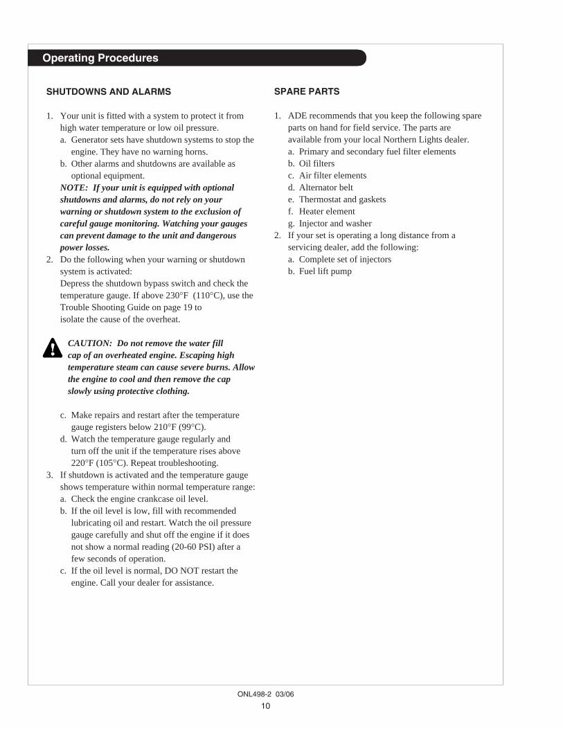
SP11. BLEEDING THE FUEL SYSTEM
CAUTION: Escaping diesel fuel underpressure can penetrate skin causing seriouspersonal injury. Before disconnecting lines besure to relieve all pressure. Before applyingpressure, be sure all connections are tight andlines, pipes and hoses aren't damaged. Fuelescaping from a very small hole can be almostinvisible. Use a piece of cardboard or wood,rather than hands, to search for suspectedleaks. If injured by escaping fuel, see a doctorat once. Serious infection or reaction candevelop if proper medical treatment isn'tadministered immediately.
Figure 10: Bleeding Fuel System
1. The fuel system is self-bleeding. However, anysystem may need manual bleeding when:a. A new fuel filter is installed;b. The engine has run out of fuel;c. The fuel lines, injection pump or any other fuelsystem component has been removed and installed.
2. Loosen bleed screw on top of the fuel filter (Figure
10). Pump hand primer on fuel lift pump until purefuel (no bubbles) escapes from bleed screw. Tightenbleed screw.
3. Loosen bleed screw on the injection pump. Pumphand primer until pure fuel (no bubbles) escapes.Tighten bleed screw.
4. If the engine does not start after this bleedingprocess, loosen a fuel line at the injector whilecranking the engine with the starter motor until purefuel escapes. Then tighten the connection. Do eachline one-at-a-time.
5. After the engine has started, use a piece of cardboardto look for fuel leaks.
SP12. INJECTOR SERVICE
1. Injectors should be checked every 500 hours. Checkshould be made by a Northern Lights dealer or localinjection repair station.
CAUTION: Escaping diesel fuel under pressurecan have sufficient force to penetrate the skincausing serious personal injury. If injured byescaping fuel, see a doctor at once.
2. Injector removal:a. Clean loose dirt from around the injectors and
the fuel lines.b. Relieve high pressure in the fuel lines by
loosening the delivery line flare nuts at eachinjector.
c. Remove delivery lines by disconnecting frominjectors and injection pump.Remove all lines as an assembly; do not removethe spacers. Cover the ends of the lines, the injectorinlets and injection pump outlets to keep dirt out.NOTE: On some models it is necessary toremove the air filter housing to access the fuelinjection lines.
d. Remove the return line retaining clamps andremove the return lines.
e. Remove the nuts on each side of the injectorbody. Remove the hold-down bracket with a6 mm wrench or socket. Pull the injector bodyfrom the hole.NOTE: Do not use pry bars to remove injectorsfrom cylinder head.
f. After removing the injectors, discard the sleevesfrom the injector hole in the head. Cover holes toprevent dirt and debris from entering the cylinders.IMPORTANT: Make sure you pull the sleeveout of the injector hole, as it may not come outwith the injector.

ONL498-2 03/06
17
3. Injector repair and cleaninga. Take injectors to your Northern Lights dealer orlocal injection repair station for testing and service.
4. Injector installation:a. Place new sleeve in injector hole. Slide injector
into hole or on the injector. replace hold-downbracket and nuts. Tighten nuts evenly to 18 - 20ft-lbs. (2.5 - 2.9 kgf-m).
b. Install fuel lines.c. Install return lines and clamps.d. Install delivery lines. Leave loose at injectors for
bleeding.e. Pump hand lever on fuel pump to fill lines.
Tighten lines at injectors. Start engine and checkfor leaks using a piece of paper or cardboard.DO NOT use hand to check for leaks.
SP13. INJECTION PUMP
1. Since operating conditions may vary considerably, itis difficult to give a definite interval for checking theinjection pump. But as a rule, pump settings,maximum speed, idle speed and exhaust smokeshould be checked after every 2000 hours ofoperation. Service of the fuel injection pump shouldonly be done if checks indicate pump malfunction.
2. Black smoke can be an indication of pumpmalfunction. Before servicing the pump, check otherpossible causes:a. Check cleanliness of air filter.b. Check valve clearances.c. Clean and check injectors.
3. Any repair which involves disassembly of theinjection pump must be carried out by speciallytrained mechanics with the proper tools and testequipment.NOTE: All warranties on the engine become nulland void if the injection pump seals are broken byunauthorized persons.
COOLING SYSTEM - GENERAL
CAUTION: The cooling water in the enginereaches extremely high temperatures. You mustuse extreme caution when working on hotengines to avoid burns. Allow the engine to coolbefore working on the cooling system. Open thefiller cap carefully, using protective clothingwhen the engine is warm.
Servicing
SP14. CHECK THE COOLANT LEVEL
1. Check the coolant level each day before starting theengine.a. Check the water level by removing the pressure
cap from the radiator. In order to give the coolingwater an opportunity to expand, the level should beabout 1 in. (2.5 cm) below the filler cap sealingsurface when the engine is cold.
b. The pressure valve in the filler cap releaseswhen the pressure is approximately 12 PSI(0.9 kgm/cm2). Use a cap pressure tester to checkcap if you suspect it is faulty.
SP15. COOLING SYSTEM FLUSHING
1. Flush the cooling system every 2000 hours or every12 months, whichever comes first.
2. Remove radiator cap and open drains on radiator andengine block. The radiator drain is a rubber cap onthe bottom of the radiator. Loosen the hose clampand remove the clamp and cap. The hex-headedengine block drain is on the service side of theengine below the intake manifold, next to theflywheel housing.
3. Pour clean water into radiator until water comingfrom radiator is clear of discoloration. Close theradiator drain and continue flushing until water fromengine drain is clear. Open all drains and drain theengine and radiator completely. Close drains andrefill the radiator with recommended coolant mixture.
4. Use 50% water / 50% ethylene glycol antifreezemix. Antifreeze mixture is recommended as a goodyear-round coolant.
5. Check hoses and connections and repair any leakage.6. Start the engine and check for leaks. Run the engine
for five minutes, then shut it down. Let engine cool,and then check the coolant level in the radiator. Addcoolant as needed.
SP16. CLEAN RADIATOR1. Remove debris from radiator fins daily.2. In very dusty applications, clean the radiator with
compressed air or steam cleaner every 100 hours.Clean in the reverse direction of the airflow.

ONL498-2 03/06
18
GENERATOR ENDS
The maintenance and operation recommendationsfor the generator end are in a separate Owner’sManual. If you do not have one of these manuals,contact your local Northern Lights dealer.
ELECTRICAL SYSTEM - GENERAL
1. Never turn an optional battery switch off or breakthe circuit between the alternator and batteries whilethe engine is running. Regulator damage can result.
2. Do NOT reverse the polarity of battery cables wheninstalling the battery.
3. When welding on the unit, disconnect the regulatorand battery. Isolate the leads.
4. Disconnect the battery cables when servicing theD.C. alternator.
5. Never test with a screwdriver, etc., against anyterminal to see if it emits sparks.
6. Do not polarize the alternator or regulator.7. A D.C. circuit breaker protects your control panel
and wiring harness. It is located in the side of thegenerator junction box.
INTAKE HEATER
Model NL498 has an optional heater element in theend of the intake manifold. To test the heaterelement, remove the power wire from the terminal.Connect D.C. test bulb between the positive (+) poleof the battery and the terminal of the heater. If thebulb lights up, the heater is functioning properly. Ifnot, the heater isn't functioning, and the heaterelements need replacing.
BOOSTER BATTERIES
CAUTION: Battery gas can explode.Keep all flames and sparks away from batteries.
1. Before changing or using booster batteries, check batteryelectrolyte level. Add distilled water if necessary.
2. Booster and main batteries must have the same voltagerating.
3. First, connect positive (+) terminal of booster batteryto positive (+) terminal of main battery. Then, connectnegative (-) terminal of booster battery to ground onthe engine block (see Figure 11).
Figure 11: Battery Connections
4. Remove booster battery after starting engine.5. Sealed batteries: See manufacturer charging and
booster instructions.
SP 17-18. BATTERY CARE1. Check electrolyte level every 50 hours or once per
month. Add distilled water to manufacturer’srecommended level.
2. Batteries, cables and cable terminals shouldbe checked and cleaned every 100 hours. Be sure tonot connect battery cables backwards (the + and -ends confused) as this could cause damage to thestator coil and the alternator diode.Clean corrosion with a water and baking sodasolution. Flush with clean water. Tighten terminalsand grease them to inhibit corrosion.
3. Check the battery condition with a hydrometer every500 hours.
SP19. WINTERIZING / OUT-OF-SERVICE1. Drain and flush the radiator and cooling system.
Leave dry or refill with antifreeze-water mixture.If refilling, start the engine and run to circulate theantifreeze.
2. Fill the fuel tank or add biocide as permanufacturer’s instructions.
3. Seal the air cleaner inlet, exhaust opening,crankcasebreather pipe, and fuel tank vent with plastic bagsand tape.
4. Change the crankcase oil and filter.5. Loosen the alternator belt.6. Disconnect and clean battery. Remove to warm
storage place if possible.7. Clean outside of unit. Paint any scratched or chipped
surfaces. Put corrosion preventative on all exposedmetal surfaces.
8. Store the set in a dry, protected place. If unit mustbe stored outside, be sure it is well protected witha cover.
Servicing

ONL498-2 03/06
19
If you cannot correct problems with these procedures, see your Northern Lights dealer.
Troubleshooting
DC ELECTRICAL SYSTEM PROBLEM POSSIBLE CAUSE RECOMMENDATION(S)
Battery Will Not Charge Loose or corroded connections • Clean and tighten battery connections.
Sulfated or worn out batteries • Check specific gravity of each battery.• Check electrolyte level of each battery.
Loose or defective alternator belt • Adjust belt tension.• Replace belt.
Starter Inoperative Check DC circuit breaker • If the breaker is tripped, reset it.
Loose or corroded connections • Clean and tighten loose battery andharness plug connection.
Low battery output • Check specific gravity of each battery.• Check electrolyte level of each battery.
Defective electrical system • Repair or replace.ground wire:
Starter Cranks Slowly Low battery output • Battery is too small.• Battery cables are too small.
Check specific gravity • Replace battery if necessary.of each battery
Check electrolyte level • If low, fill cells with distilled water.of each battery
Crankcase oil too heavy • Fill with oil of appropriate viscosity.
Loose or corroded connections • Clean and tighten loose connections.
Entire Electrical System Check DC circuit breaker • If breaker is tripped, reset it.Does Not Function Faulty connection • Clean and tighten battery and harness
plug connections.
Sulfated or worn out batteries • Check specific gravity and electrolytelevel of each battery.
ONL498-2 03/06
20
Troubleshooting
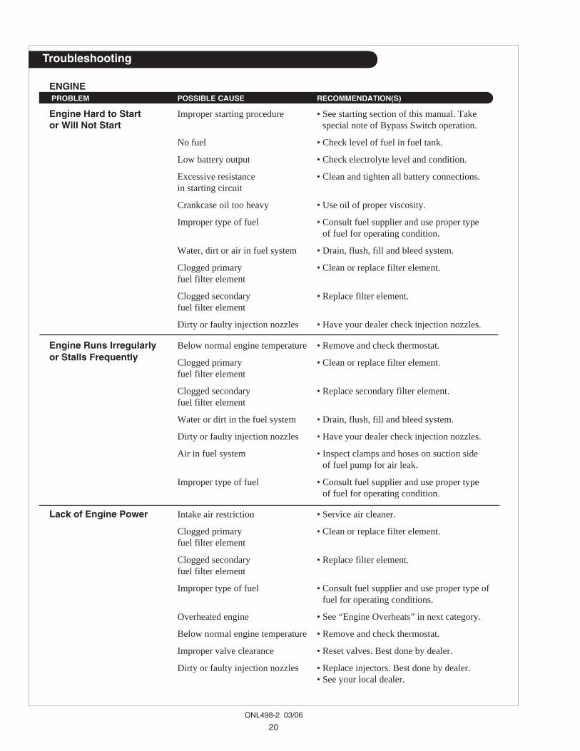
ENGINE PROBLEM POSSIBLE CAUSE RECOMMENDATION(S)
Engine Hard to Start Improper starting procedure • See starting section of this manual. Takeor Will Not Start special note of Bypass Switch operation.
No fuel • Check level of fuel in fuel tank.
Low battery output • Check electrolyte level and condition.
Excessive resistance • Clean and tighten all battery connections.in starting circuit
Crankcase oil too heavy • Use oil of proper viscosity.
Improper type of fuel • Consult fuel supplier and use proper typeof fuel for operating condition.
Water, dirt or air in fuel system • Drain, flush, fill and bleed system.
Clogged primary • Clean or replace filter element.fuel filter element
Clogged secondary • Replace filter element.fuel filter element
Dirty or faulty injection nozzles • Have your dealer check injection nozzles.
Engine Runs Irregularly Below normal engine temperature • Remove and check thermostat.or Stalls Frequently Clogged primary • Clean or replace filter element.
fuel filter element
Clogged secondary • Replace secondary filter element.fuel filter element
Water or dirt in the fuel system • Drain, flush, fill and bleed system.
Dirty or faulty injection nozzles • Have your dealer check injection nozzles.
Air in fuel system • Inspect clamps and hoses on suction sideof fuel pump for air leak.
Improper type of fuel • Consult fuel supplier and use proper typeof fuel for operating condition.
Lack of Engine Power Intake air restriction • Service air cleaner.
Clogged primary • Clean or replace filter element.fuel filter element
Clogged secondary • Replace filter element.fuel filter element
Improper type of fuel • Consult fuel supplier and use proper type offuel for operating conditions.
Overheated engine • See “Engine Overheats” in next category.
Below normal engine temperature • Remove and check thermostat.
Improper valve clearance • Reset valves. Best done by dealer.
Dirty or faulty injection nozzles • Replace injectors. Best done by dealer.• See your local dealer.

ONL498-2 03/06
21
Troubleshooting
ENGINE PROBLEM POSSIBLE CAUSE RECOMMENDATION(S)
Engine Overheats Low coolant level • Fill tank or radiator to proper level.• Check hoses for loose connections
and leaks.
Cooling system needs flushing • Flush cooling system.
Defective thermostat • Remove and check thermostat.
Defective temperature gauge • Check water temperature with thermometerand replace gauge if necessary.
Fan belt loose • Adjust belt tension (see page 12).
Engine Knocks Insufficient oil • Call your dealer.
Injection pump out of time • Call your dealer.
Below normal engine temperature • Check your thermostats.• Check water temperature to see if
temperature gauge is working properly.
Engine overheating • See “Engine Overheating” section.
Connecting rod bolt loose • Tighten to torque 44.1 to 49.0 N•m (4.5 kgf- m to 5.0 kgf-m).
High Fuel Consumption Improper type of fuel • Use correct fuel for temperature.
Clogged or dirty air cleaner • Service air cleaner.
Improper valve clearance • See your dealer.
Injection nozzles dirty • See your dealer.
Injection pump out of time • See your dealer.
Engine not at proper temperature • Check your thermostats.• Check water temperature with thermometer
and replace gauge if necessary.
Below Normal Thermostats not working properly • Check thermostats.Engine Temperature Temperature gauge • Check water temperature with thermometer.
not working properly
Low Oil Pressure Low oil level • Fill crankcase to proper level.
Improper type of oil • Drain and fill crankcase with correct oil.
Partially plugged oil filter • Replace filter.
High Oil Consumption Break-in period • Oil consumption decreases after break in.
Crankcase oil too light • Use proper viscosity oil.
Oil leaks • Check for leaks in lines around gasketsand drain plug.
If you cannot correct problems with these procedures, see your Northern Lights dealer.

ONL498-2 03/06
22
Troubleshooting
ENGINE PROBLEM POSSIBLE CAUSE RECOMMENDATION(S)
Engine Emits Black Clogged or dirty air cleaner • Service air cleaner.or Gray Exhaust Smoke Defective muffler • Have dealer check back pressure.
(back pressure too high)
V belt loose • Adjust the belt (see page 12).
Improper fuel • Use correct fuel for temperature.
Injection nozzles dirty • See your dealer.
Engine out of time • See your dealer.
Leak in intake line. • Repair or replace.
Intake and exhaust valve timingnot set properly • Adjust valve clearance (see page 12).
Engine Emits Improper fuel • Use correct fuel for temperature.White Smoke Cold engine • Warm up engine to normal operating
temperature.
Defective thermostat • Remove and check thermostat.
Engine out of time • See your dealer.
Fuel injection not spraying • See your dealer for repair.correctly
Intake and exhaust valve timing • Adjust valve clearance (see page 12).not set properly
If you cannot correct problems with these procedures, see your Northern Lights dealer.

ONL498-2 03/06
23
AC Wiring Diagram
NL4
98K
2 A
C W
iring
Dia
gram
12 &
4 L
ead
Gen
erat
ors
DS
T-51
-DF
K A
VR
B-7
198E
Wir
ing
diag
ram
s su
bjec
t to
chan
ge w
itho
ut n
otic
e.
ONL498-2 03/06
24
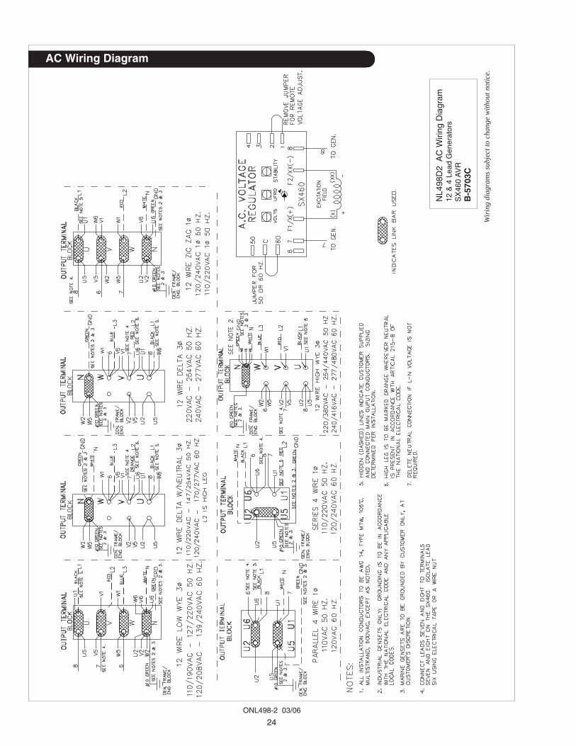
AC Wiring Diagram
NL4
98D
2 A
C W
iring
Dia
gram
12 &
4 L
ead
Gen
erat
ors
SX
460
AV
RB
-570
3C
Wir
ing
diag
ram
s su
bjec
t to
chan
ge w
itho
ut n
otic
e.

ONL498-2 03/06
25
DC Wiring Diagram
NL4
98K
2 D
C W
iring
Dia
gram
12 V
olt S
tand
ard
Gro
und
B-8
613A
Wir
ing
diag
ram
s su
bjec
t to
chan
ge w
itho
ut n
otic
e.
ONL498-2 03/06
26
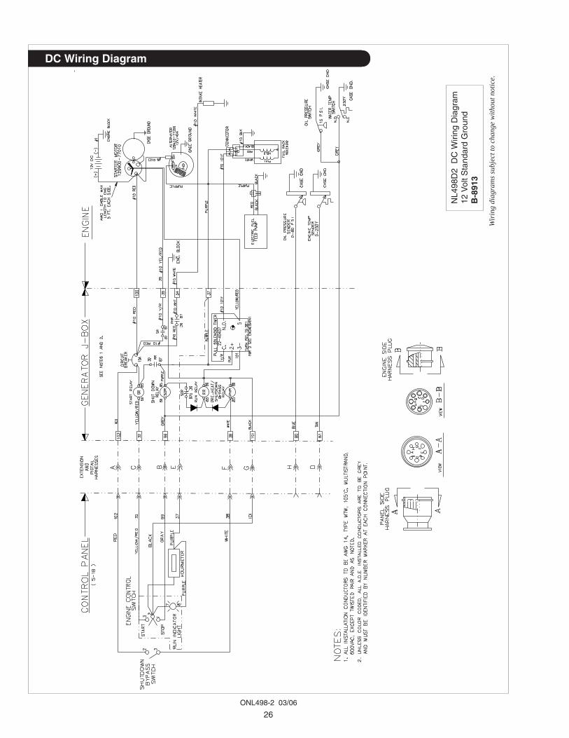
DC Wiring Diagram
NL4
98D
2 D
C W
iring
Dia
gram
12 V
olt S
tand
ard
Gro
und
B-8
913
Wir
ing
diag
ram
s su
bjec
t to
chan
ge w
itho
ut n
otic
e.
NORTHERN LIGHTS4420 14th AVE. N.W.SEATTLE, WA 98107-5043USA
TEL: (206) 789-3880FAX: (206) 782-5455http://www.northern-lights.com


![Notice for TAIYO YUDEN Products [ For General … for TAIYO YUDEN Products [ For General Electronic Equipment ] Please read this notice before using the TAIYO YUDEN products. REMINDERS](https://static.fdocuments.in/doc/165x107/5c85e46209d3f2700a8b9840/notice-for-taiyo-yuden-products-for-general-for-taiyo-yuden-products-for-general.jpg)
