OPERATOR’S MANUALs3.amazonaws.com/.../669928/attach/2204698_0_TCM_O-470_OpsMan_X3009… · frame,...
100
Publication X30097 © CONTINENTAL MOTORS, INC. AUGUST 2011 O-470-A, B, E G, J, K L, M, R S & U CONTINENTAL® AIRCRAFT ENGINE OPERATOR’S MANUAL FAA APPROVED
Transcript of OPERATOR’S MANUALs3.amazonaws.com/.../669928/attach/2204698_0_TCM_O-470_OpsMan_X3009… · frame,...

Publication X30097©CONTINENTAL MOTORS, INC. AUGUST 2011
O-470-A, B, EG, J, KL, M, RS & U
CONTINENTAL® AIRCRAFT ENGINE
OPERATOR’SMANUAL
FAA APPROVED
A O-470 Series Engine Operator’s Manual31 August 2011
Supersedure Notice
This manual revision replaces the front cover and list of effective pages for Publication Part No. X30097, dated April 1985. Previous editions are obsolete upon release of this manual.
Effective Changes for this Manual0........................April 19851............... 31 August 2011
List of Effective Pages
Document Title:O-470 Series Engine Operator’s ManualPublication Number: X30097 Initial Publication Date: April 1985 Page Change Page Change Page Change Page ChangeCover ..............................1A......................................1i .......................................1ii thru vi............................01-1 thru 1-2 .....................02-1 thru 2-6 .....................03-1 thru 3-12 ...................04-1 thru 4-4 .....................05-1 thru 5-24 ...................06-1 thru 6-8 .....................07-1 thru 7-4 .....................08-1 thru 8-6 .....................19-1 thru 9-8 .....................010-1 thru 10-8 .................011-1 thru 11-6..................0
Published and printed in the U.S.A. by Continental Motors, Inc.
Available exclusively from the publisher: P.O. Box 90, Mobile, AL 36601.
Copyright © 2011 Continental Motors, Inc. All rights reserved. This material may not be reprinted, republished, broadcast, or otherwise altered without the publisher's written permission. This manual is provided without express, statutory, or implied warranties. The publisher will not be held liable for any damages caused by or alleged to be caused by use, misuse, abuse, or misinterpretation of the contents. Content is subject to change without notice. Other products and companies mentioned herein may be trademarks of the respective owners.

i
NOTICE
IN ORDER TO PROPERLY USE THIS ENGINE,THE USER MUST COMPLY WITH ALLINSTRUCTIONS CONTAINED HEREIN.FAILURE TO SO COMPLY WILL BE DEEMEDMISUSE, RELIEVING THE ENGINEMANUFACTURER OF ANY RESPONSIBILITY.
THIS MANUAL CONTAINS NO WARRANTIES,E ITHER EXPRESS OR IMPLIED. THEPURPOSE OF THE DATA PRESENTED ISINSTRUCTION, INFORMATION, AND SAFETY.
Continental Motors engine operating instructionsare generated prior to and independently of theaircraft operating instructions established by theairframe manufacturer. Continental Motorsengine operating instructions are developedusing factory controlled parameters that are notnecessarily the same as those specificationsrequired to satisfy a specific aircraft I engineinstallation. Because of this difference theaircraft operator should use the air framemanufacturer's operating instructions found inthe Pilots Operating Handbook (POH) whileoperating the aircraft unless otherwise specifiedby the original airframe manufacturer.
INTRODUCTION
SECTION
TABLE OF CONTENTS
I Design Features
Page
vi
1-1
II Specifications and -Limits .................... 2-1
III Normal Operating Procedures ................ 3-1
IV In-Flight Emergency Procedures .............. 4-1
V Engine Performance and Cruise Control ....... 5-1
VI Abnormal Environmental Conditions ......... 6-1
VII Engine Description ......................... 7-1
VI I I Servicing and Inspection ..................... 8-1
IX Troubleshooting. . . . . . . . . . . . . . . . . . . . . . . . . . . . 9-1
X Storage and Removal From Storage .......... 10-1
XI Glossary. ... . . . . . . . . . . . .. . . . . . . . . . . . . . . . .. 11-1
ii
____ --'~~___ _ ___ ~-__ ----~o~~ ___ ~:~ _____ ~~ ____ ~~ __ ~ ________________ _
-----~--l
LIST OF IttUSTRATIONS
FIGURE PAGE
Sea Level Performance for 0-470-A 5-3
2 Altitude Performance for 0-470-A ............ 5-4
3 Sea Level Performance for 0-470-8 ........... 5-5
4 Altitude Performance for 0-470-8 ............ 5-6
5 Sea Level Performanee for 0-470-E ........... 5-7
6 Altitude Performance for 0-470-E ............ 5-8
7 Sea Level Performance for 0-470-G .......... 5-9
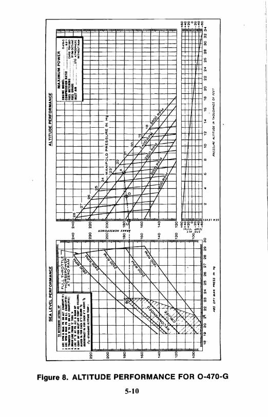
8 Altitude Performance for 0-470-G ............ 5-10
9 Fuel Flow Limits for 0-470-G ................. 5-11
10 Sea Level Performance for 0-470-J ........... 5-12
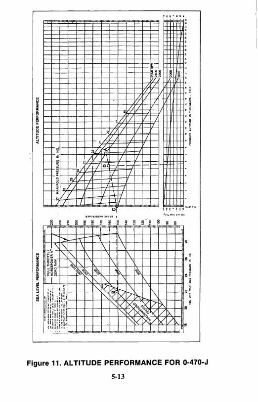
II Altitude Performance for 0-470-J ............ 5-13
12 Fuel Flow Limits for 0-470-J ................. 5-14
13 Sea Level Performance for 0-470-K&L .. . . . . .. 5-15
14 Sea Level Performance for 0-470-R&S ......... 5-16
15· Altitude Performance for 0-470-K,L,R&S . . . . .. 5-17
16 Fuel Flow Limits for 0~470-K,L,R&S .......... 5-18
17 Sea Level Performance for 0-470-M .......... 5-19
18 Altitude Performance for 0-470-M ........... 5-20
19 Fuel Flow Limits for 0-470-M ............... 5-21
20 Sea Level Performance for 0-470-U .......... 5-22
21 Altitude Performance for 0-470-U ............ 5-23
22 Fuel Flow Limits for 0-470-U ............ ;... 5-24
23 Lubrication Diagram ....................... 7-2
24 Wiring Diagram ............................ 7-3
iii

INTRODUCTION
This booklet is intended to provide pilots, operators and main-tenance personnel with recommended procedures relating to engine operation, servicing and periodic maintenance. Subjects are limited to engine operation and inspection normally carried out on engines installed in aircraft. No effort is made herein to describe extensive repair work or overhaul. For such instructions, refer to the appli-cable overhaul manual. Careful observation of operating limits and compliance with recommen~ed inspection procedures herein will result in greater engine relia bility.
The operating instructions outlined in this manual have been developed for general airframe installation; for a particular air-frame, refer to the appropriate aircraft operator's manual. Recom-mendations, cautions and warnings regarding operation of this engine are not intended to impose undue restrictions on operation of the aircraft, but are inserted to enable the pilot to obtain maximum performance from the engine commensurate with safety and efficiency. Abuse, misuse or neglect of any piece of equipment can cause eventual failure. In the case of an aircraft engine it should be obvious that a failure may have disastrous consequences. Failure to observe the instructions contained in this manual constitutes unauthorized operation in areas unexplored during development of the engine, or in areas in which experience has proved to be un-desirable or detrimental.
Notes, Cautions and Warnings are included throughout this manual. Application is as follows:
NOTE: Special interest information which may facilitate the operation of equipment.
CAUTION: Information issued to emphasize certain instructions or to pre\'ent possihle damaRe 10 el1Rine or accessories.
WARNINGS: Information which, if disregarded, may result in severe damage or destruction of the engine or endangerment to personnel.
iv

Users are advised to keep up with latest information by means of service bulletins, which are available for study at any approved Teledyne Continental Motors Distributor location, and are also available on an annual subscription basis. Subscription forms are available at Distributors or from Teledyne Continental Motors, P.O. Box 90, Mobile, Alabama 36601, Attention: Publications Department.
WARNING ... This engine must be installed in accordance with all requirements ang limitations listed in the Specifi-cations and Limits for Teledyne Continental Aircraft Engines.
v

- -.-=.~.=~==~~~-------------------------.----~----
SECTION I
DESIGN FEATURES
The engines have overhead valve cylinders with 5.00 inch bore, 4.00 inch stroke, 471 cubic inch displacement and a compression ratio of 7.0:1. The exception is a compression ratio of 8.0:1 for the 0-470-B, G & M Engines and 8.6: I for the 0-470-U. The cylinders have down-directed exhaust outlets. All models with the exception ofO-470-A, E & J, have rotation provided for the exhaust valves by the use of rotators. The crankshaft is equipped with pendulum-type torsional damper weights. The engines have removable-type hydraulic tappets. Tappets, pushrod ends and rocker arm bearings are lubri-cated by the engine main oil pressure system.
The engines are furnished with a direct cranking starter and a belt-driven generator or alternator. The exhaust systems are not supplied with the engines. The engine main fuel filter, engine cntrols, vacuum pump and propeller governor are furnished by the aircraft manufacturer.
The relatively high power delivered by the engines, per pound of weight, is achieved by utilization of carefully selected high strength materials, by improvements in design calculated to make the most of these high quality materials, and by very close control of critical dimensions, surface finishes, heat treatment and hardening processes. Careful work has produced more rugged engines than could be built by less exacting methods; however, no amount of ruggedness built into an engine will enable it to withstand serious mistreatment. Overheating, neglect and inferior fuels and lubricants will seriously affect engine performance, particularly when the specific power rating is high and each part must be free to function properly in order to withstand the imposed loads with minimum wear. These considerations are mentioned here in order to empha-size the necessity of using only the manufacturer's recommended gasoline and oil and of keeping the fuel, oil and air filters clean. The octane rating of engine fuel should be as specified under detailed specifications in Section II.
1-1

~-----------------------------------------------------------------------------------
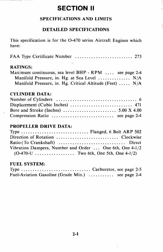
SECTION II
SPECIFICATIONS AND LIMITS
DETAILED SPECIFICATIONS
This specification is for the 0-470 series Aircraft Engines which have:
FAA Type Certificate Number ......................... 273
RATINGS: Maximum continuous, sea level BHP - RPM .... see page 2-4
Manifold Pressure, in. Hg. at Sea Level .............. N / A Manifold Pressure, in. Hg. Critical Altitude (Feet) ..... N /A
CYLINDER DATA: Number of Cylinders ................................... 6 Displacement (Cubic Inches) ........................... 471 Bore and Stroke (Inches) ....................... 5.00 X 4.00 Compression Ratio ........................... see page 2-4
PROPELLER DRIVE DATA: Type ............................. Flanged, 6 Bolt ARP 502 Direction of Rotation ........................... Clockwise Ratio (To Crankshaft) ............................. Direct Vibration Dampers, Number and Order ... One 6th, One 4-1/2
(0-470-V ................. Two 6th, One 5th, One 4-1/2)
FUEL SYSTEM: Type .............................. Carburetor, see page 2-5 Fuel-Aviation Gasoline (Grade Min.) ........... see page 2-4
2-1
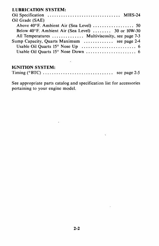
LUBRICATION SYSTEM: Oil Specification ................................ MHS-24 Oil Grade (SAE)
Above 40°F. Ambient Air (Sea Level) .................. 50 Below 40°F. Ambient Air (Sea Level) ........ 30 or IOW-30 All Temperatures .............. Multiviscosity, see page 7-3
Sump Capacity, Quarts Maximum ............. see page 2-4 Usable Oil Quarts 15° Nose Up ........................ 6 Usable Oil Quarts 15° Nose Down ...................... 6
IGNITION SYSTEM: Timing (0 BTC) ............................... see page 2-5
See appropriate parts catalog and specification list for accessories pertaining to your engine model.
2-2
~ I ~
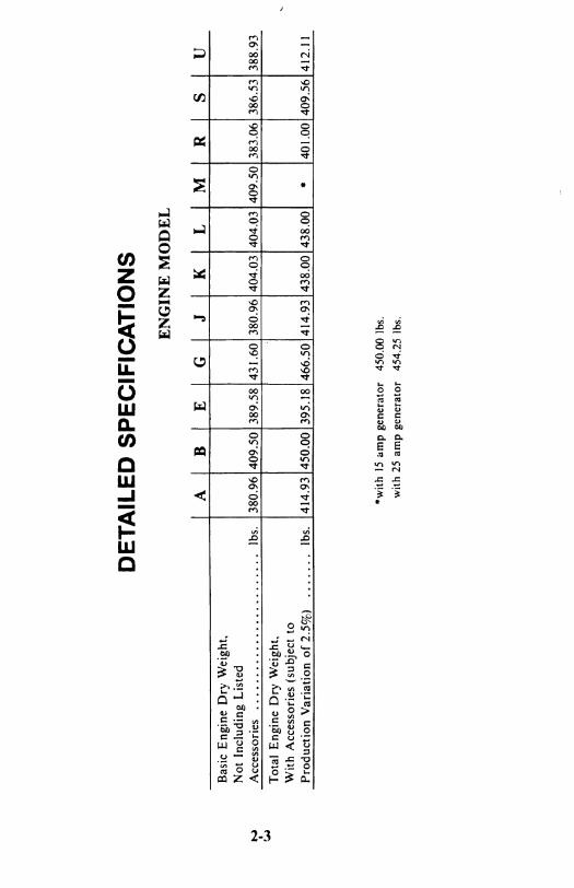
DETAILED SPECIFICATIONS
Basic Engine Dry Weight, Not Including Listed Accessories ........................ Ibs. Total Engine Dry Weight, With Accessories (subject to Production Variation of 2.5%) ....... Ibs.
ENGINE MODEL
A B E G J
380.96 409.50 389.58 431.60 380.96
414.93 450.00 395.18 466.50 414.93
·with 15 limp generator 450.00 Ibs. with 25 amp generator 454.25 Ibs.
K L
404.03 404.03
438.00 438.00
M R S U
409.50 383.06 386.53 388.93
* 401.00 409.56 412.1 I

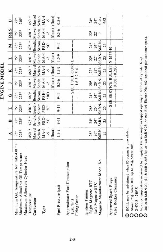
DETAILED SPECIFICATIONS
ENGINE MODEL
A B E G J K L M R&S U Type Certificate Number 273 273 273 273 273 273 273 273 273 273 Number of Cylinders 6 6 6 6 6 6 6 6 6 6 Cylinder Bore (inches) 5.00 5.00 5.00 5.00 5.00 5.00 5.00 5.00 5.00 5.00 Piston Stroke (inches) 4.00 4.00 4.00 4.00 4.00 4.00 4.00 4.00 4.00 4.00 Total Displacement (cubic in.) 471 471 471 471 471 471 471 471 471 471
Compression Ratio 7.0:1 8.0:1 7.0:1 8.0:1 . 7.0:1 7.0:} 7.0:1 8.0:1 7.0:1 8.6:1 Rated Maximum Continuous BHP 225 240 225 240. 225 230 ' 230 240 230 230
N Rated Maximum Continuous RPM 2600 2600 2600 2600 2550 2600 2600 2600 2600 2400 I
"" Rated Take-Off HP 225 240 225 240 225 230 230 240 230 230 Rated Maximum Take-Off RPM 2600 2600 2600 2600 2550 2600 2600 2600 2600 2400
Recommended Cruise RPM 2300 2300 2300 2300 2300 2300 2300 2300 2300 2400 Recommended Cruise Manifold
Pressure (in. Hg.) 23 23 23 23 23 23 23 23 23 23 Minimum Fuel Grade 80 J 100ll 80 J 100ll . 80 J 80 J 80 J 100ll 80 I 100LL Oil Pressure (cruise - Ib./sq. in.) 30-60 30-60 30-60 30-60 30-60 30-60 30-60 30-60 30-60 30-60
Oil Pressure Minimum (idling - Ib./sq.in.) 10 10 10 10 10 10 10 10 10 10 Oil Sump Capacity (qts.) 12 12 12 12 . ~ 12 . 12 . 12 12 12 12 Minimum Oil Le\'el for Operation -- --I ,miCA ED B LOW MARl< ON D PSTIC -- --Minimum Oil Consumption at Rated Power & RPM (Ibs. BHP 'hr.) .018 .015 .018 .015 .018 .012 .012 .012 ~ ~
--- ----------_ .. _--- ----
------- --~- ------------
N I
VI
Minimum Oil. Temperature for Take-Off 0 F. Maximum Allo\\'iible Oil Temperature
I Maximum Allowable Cylinder Head Temperature
Carburetor
Type
A 75°
·225°
450 4
Marvel Scheb. MA-4
-5
B E 75° 75°
225° 225°
475 4 450 4
Bendix Bendix Strom. Strom. PSD- PSD-
5C 5C
ENGINE MODEL
G J K L M R&S U 75° 75° 75° 75° 75° 75° 75°
225° 225° 225° 225° 225° 225° 240°
4604 460 4 460 4 460 4 475 4 460 4 460 Bendix Marvel Marvel Marvel Bendix Marvel Marvel Strom. Scheb. Scheb .. Scheb. Strom. Scheb. Schch. PSH- MA-4 MA-4 MA-4 PSD- MA-4 MA-4 5BD -5 -5 -5 5C -5 -5
(float) (float) I (float) I (float) (float) I (float)
F~el Pressure (psi) 1.5-9 I 9-11 9-11 9-11 0.5-6 I 1.5-9 I 1.5-9 I 9-11 0.5-6 I 0.5-6
Approximate Fuel Consumption (gal.l hr.)
Firing Order
Ignition Timing Right Magneto BTC Left Magneto BTC
Magneto Manufacturer Model No.
Approved Spark Plugs Valve Rocker Clearance
-- -t-- S~E FUEL CURltE --,----l---+- 1-6-3h-5-4 -I---~
26° 24° 26° 24° 20° .22° 2r 24° I 22° 26° 24° 26° 24° 20° 22° 22° 24° 22°
S6RN- S6RN- S6RN- S6RN- S6RN- S6RN- S6RN- S6RN-25 25 25 25 25 25 25 25
f---+-- SEJ: SER'fICE BtJLLETIN M77\-10 -~---1.---4 0.060 t 0.200 t--_J-
o 1001.1. rna\' he substituted when XO octane is unavailahle. o Ahove 75% power .OOH. up to 75% power .000, G 0-470-S - 2400 F. o Indicates temperature measured hy plug-type thcrm()(:oupic in tapped opening at hottom of cylinder head, o One each SliRN-201 (I.) & SoRN-205 (R): or two SliRN-2S: or two Slick Eil:ctro No. lif>2 (optional per customer spec.).
24° 24°
Slick 662


SECTION III NNNO
ROCEDURE
CA LIT/ON . .. This se("fion pertains to/light operations conducted under" Standardized Day" conditions. The pilot should thoroughly familiari::e himself with the Section on Abnormal Operating COfl(/iliof1.\'. Whene\'er such abnormal condilions are encoul1lered or alllicipaled. Ihe procedures and Techniques/or normal operaTion should he lailored {[ccordingZI', For example, tithe aircraft is 10 be Temporarily operaled ill exTreme cold or hot lI'emller, consideraTion should be given To all early oil change and/or a rOUTine inspection sen'icing.
GENERAL
The life of your engine is determined by the care it receives. Follow the instructions contained in this manual carefully.
The engine receives a run-in operation before leaving the factory. Therefore, no break-in schedule need be followed. Straight mineral oil (MIl-C-6529 Type II) should be used for the first oil change period (25 hours).
The minimum grade aviation fuel is 80 octane for models A. E. J, K, L, Rand Sand 1001 100lL for models B, G, M, U. A grade offuel other than that specified should be limited to emergencies only. In case the grade required is not available, use a higher rating. Never use a lower rated fuel. Using higher octane fuels may cause higher cylinder temperatures and engine instruments should be closely monitored, staying within normal limits. (See Section II) ..
WARNING ... The use of a lower octane rated fuel can cause pre-ignition or detonation, which can damage an engine the first time high power is applied. This will most likel)' occur on takeoff. If the aircraft is inadvertently serviced with the wrong grade of fuel, completely drain and properly service fuel tank/tanks.
NOTE ... The following checklists are general in nature, since the various airframelpowerplant combinations are not necessarily the same in setup and layout. Consult your own pilot's operating hand-book for the specific challenge and response checklists required for your aircraft.
3-1

_~ __ ~ ___ ~~. ~~_~ ____ ~~~ __________ . _______ ~ __________ -- ---~- -O---·~-·---------------I
PRESTARTING
Before each flight the engine and propeller must be examined for damage, oil leaks, security and proper servicing.
I. Place the ignition switch to the "OFF" position.
2. Operate all controls and check for binding and full range of travel.
3. Assure that fuel tanks contain proper grade and quantity of fuel.
4. Drain a quantity of fuel from all sumps and strainers into a clean container. If water or foreign matter is noted. continue drain-ing until only clean fuel appears.
5. Check oil level in sump.
6. Check cowling for security.
STARTING
I. Fuel Selector - ON, appropriate tank.
2. Propeller Control - HIGH RPM.
3. Mixture Control - FULL RICH
4. Battery Switch - ON.
5. Throttle - FULL OPEN.
6. Boost Pumps or Primer - ON. 2 to 3 seconds.
7. Throttle - 1/2 INCH OPEN.
8. Magneto/Start Switch - START position.
Release the Magneto/Start Switch to BOTH position as soon as the engine starts.
3-2
CA UT/ON ... Do nol el1RaRe Ihe .\'Iarter when Ihe engine is running as Ihis lI'ill danlage Ihe :\'tarter, Do nol crankfor/onger than thiN.\' seconds al a lime. as Ihis may cause Ihe starter molOr to overheat. If Ihe ellRine does 1101 Slarl ({Iier Ihirl.\' seconds of cranking. allow a 3 105 lIIinllfe cooling period before allempling to restart.
CAUTION . .. If ellRine kicks hack II'hen slarting. DO NOTallempt 10 Slarl. The ignition .\·Ial'ling system is inoperative and must be repaired hefore damaging Slarler adapter assembly.
( ('old Starts)
a. Throttle - FULL OPEN.
b. Mixture Control - FULL RICH.
c, Primer - ON, 2 to 3 seconds.
d. Throttle - 1/2 INCH OPEN.
e. Magneto/Start Switch - START position.
f. Once engine starts, it may be necessary to keep engine running with primer.
g. Magneto/Start Switch - BOTH position.
(Flooded Engine)
a. Mixture Control - IDLE CUT-OFF.
b. Throttle - FULL OPEN.
c. Magneto/Start Switch - START.
d. Once engine starts, release Magneto/Start Switch to BOTH. Retard the throttle to 1000 RPM and slowly advance the mixture control to FULL RICH position.
3-3
(Hot Starts)
a. Throttle - FULL OPEN.
b. Mixture Control· IDLE CUT-OFF.
c. Boost Pump - (if airframe equipped) ON, 10-15 seconds or until the fuel pumping pulsations stabilize.
d. Mixture Control - FULL RICH. momentary priming may be required.
e. Throttle - Retard to 1/2 INCH.
f. Magneto/Start Switch - START position.
g. Once engine starts, release Magneto/Start Switch to BOTH.
STARTING (Cont'd.)
9. Throttle 1000 to 1500 RPM.
10. Oil Pressure - ABOVE 30 POUNDS WITHIN 30 SECONDS.
II. Alternator Switch - ON.
12. Use the same procedure to start other engine, if operating a twin engine installation.
GROUND RUNNING: WARM-UP
Teledyne Continental aircraft engines are aircooled. and therefore dependent upon the forward speed of the aircraft for cooling. To prevent overheating, it is important that the following rules be observed.
I. Head the aircraft into the wind.
2. During ground operations the propeller should be in the "Full Increase" RPM position.
3-4

3. Avoid prolonged idling at low RPM. Fouled spark plugs can result from this practice.
4. Leave mixture in "Full Rich". (See "Ground Operation at High Altitude Airports," Section VI for exceptions).
5. Warm-up 900-1000 RPM.
PRE-TAKEOFF CHECK
I. Maintain engine speed at approximately 1000 to 1500 RPM for at least one minute in warm weather, and as required during cold weather to prevent cavitation in the oil pump and to assure adequate lubrication.
2. Advance throttle slowly until tachometer indicates an engine speed of 1200 RPM. Allow additional warm-up time at this speed depending upon ambient temperature. This time may be used for taxiing to take-off position. The minimum allowable oil tempera-ture for run-up is 75° F.
CAUTION . .. Do not operate the engine at run-up speed unless oil temperalllre is 75° F. minimum.
3. Perform all ground operations with cowl flaps, if installed, full open, mixture control in "FULL RICH" and the propeller control set for "Full Increase" RPM (except for brief testing of propeller governor).
4. Restrict ground operations to the time necessary for warm-up and testing.
5. Increase engine speed to 2000 RPM only long enough to perform the following checks:
a. Magnetos: With both magnetos "ON", position the right magneto switch "OFF" and note engine RPM; now back to bot h magnetos "ON" to clear the spark plugs. Then position the left magneto switch "OFF" and note engine RPM. Now return switch to both magnetos "ON". The difference between the two
3-5

magnetos operated individually should not differ more than 50 RPM with a maximum drop for either magneto of 150 RPM. Observe engine for excessive roughness during this check.
If no drop in RPM is observed when operating on either magneto alone, the switch circuit should be inspected.
WARNING ... Absence of RPM drop when checking magnetos may indicate a malfunction in the ignition circuit. This type of malfunction should be corrected prior to con-tinued operation of the engine. Should the propeller be moved by hand (as during preflight) the engine may start and cause injury to personnel.
CAUTION . .. Do not underestimate the imporlance of a pretakeoff magneto check. When operating on single ignition. some RPM drop should be noted. Normal indications should be a 25-75 RPM drop and slight engine roughness as each magnelo is switched o.ff. Absence o.f a magneto drop may be indicative (~f an open switch circuit or an improperly timed magneto. A drop in RPM that exceeds 150 may indicate a faulty magneto or fouled spark plugs.
b. Minor spark plug fouling can usually be cleared as follows:
(I) Magnetos - Both On.
(2) Throttle - 2200 RPM.
(3) Mixture - Move toward idle cutoff until RPM peaks and hold for ten seconds. Return mixture to full rich.
(4) Magnetos - Recheck (per paragraph 5a).
If the engine is not operating within specified limits, it should be inspected and repaired prior to continued opera-tional service.
CA UTION ... Avoid prolonged single magneto operation to preclude fouling o.f the spark plugs.
3-6
c. Check throttle and propeller operation.
(I) Move propeller governor control toward low RPM position and observe tachometer. Engine speed should de-crease to minimum governing speed (200-300 RPM drop). Return propeller control to "Full Increase" RPM. Repeat this procedure two or three times to circulate warm oil into the propeller hu b.
(2) In aircraft installed with full feathering propellers, move propeller to "feather" position. Observe for 300 RPM drop below minimum governing RPM, then return control to "full increase" RPM position.
CA UT/ON . .. Do not operate the engine at a speed in excess of2000 RPM longer than necessary 10 test operation and observe engine instruments. Proper engine cooling depends uponforward speed of the aircraft. Discontinue testing ((temperature or pressure limits are approached.
6. Instrument Indications
a. Oil Pressure: The oil pressure relief valve will maintain pressure within the specified limits if the oil temperature is within the specified limits and if the engine is not excessively worn or dirty. Fluctuating or low pressure may be due to dirt in the oil pressure relief valve or congealed oil in the system.
b. Oil Temperature: The oil cooler and oil temperature control valve will maintain oil temperature within the specified range unless the cooler oil passages or air channels are obstructed. Oil tempera-ture above the prescribed limit may cause a drop in oil pressure, leading to rapid wear of moving parts in the engine.
c. Cylinder Head Temperature: Any temperature in excess of the specified limit may cause cylinder or piston damage. Cooling of the cylinders depends upon the cylinder baffles· being positioned properly on the cylinder heads, barrels and in other locations in the pressure compartment to direct air between the cylinder fins. Fuel and air mixture ratio will affect cylinder temperature. Excessively
3-7
lean mixture causes overheating even when the cooling system is in good condition. High power and low air speed, or any slow speed flight operation, may cause overheating by reducing the cooling air flow. The engine depends upon ram air flow developed by the forward motion of the aircraft for adequate cooling.
d. Battery Charging: The ammeter should indicate a negative charging rate while the engine is being started. The ammeter reading should return to the positive side as soon as the engine starts and RPM increases. A low cha~ging rate is normal after the initial recharging of the battery. A zero reading or negative reading with electrical load may indicate a malfunction in the alternator or regulator system.
TAKEOFF
I. Position mixture to "FULL RICH". Where ins~alled, cowl flaps should be in the "Open" position.
2. Position propeller control in "FULL INCREASE" RPM position.
3. Position fuel boost pump switch if equipped, as instructed by aircraft manufacturer.
4. After slowly advancing the throttle to the "FU LL OPEN" position insure a minimum oil temperature of 75° F.
3-8
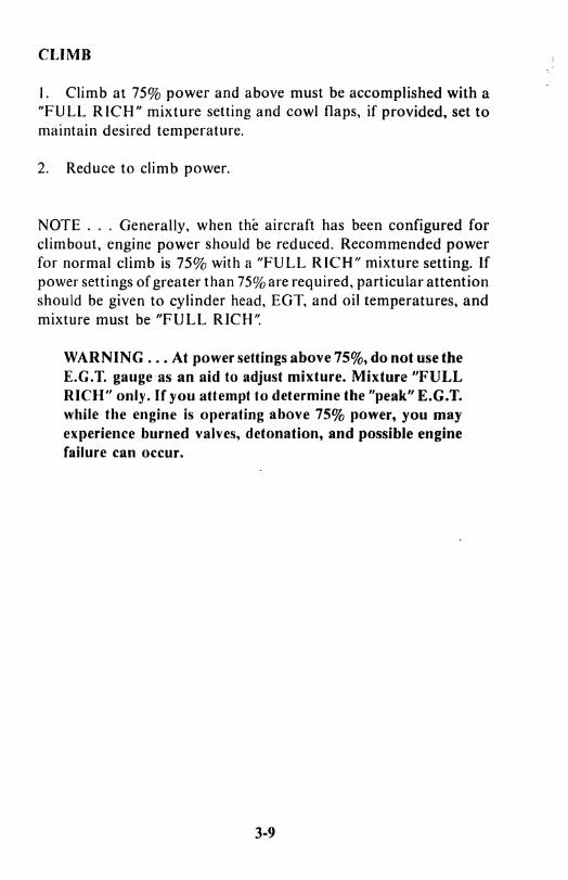
-~~~~---~~----------~-- -----~. I CLIMB
I. Climb at 75% power and above must be accomplished with a "FULL RICH" mixture setting and cowl flaps, if provided, set to maintain desired temperature.
2. Reduce to climb power.
NOTE ... Generally. when the aircraft has been configured for climbout, engine power should be reduced. Recommended power for normal climb is 75% with a "FULL RICH" mixture setting. If power settings of greater than 75% are required. particular attention should be given to cylinder head. EGT. and oil temperatures, and mixture must be "FULL RICH'~
WARNING ... At power settings above 75%, do not use tbe E.G.T. gauge as an aid to adjust mixture. Mixture "FULL RICH" only. If you attempt to determine the "peak" E.G.T. while the engine is operating above 75% power, you may experience burned valves, detonation, and possible engine failure can occur.
3-9

CRUISE
I. Set Manifold pressure and RPM for cruise power selected.
2. When engine temperatures have stabilized at cruise condition (usually within 5 minutes after leveling of I), adjust mixture to obtain specified fuel flow. See Engine Performance and Cruise Control section of this manual or aircraft manufacturer's instruc-tions.
3. When a leaned mixture setting is used. and climb power is desired, the mixture control rhust be returned to "FULL RICH" before changing the throttle or propeller setting. When reducing power, retard throttle, adjust R PM and then adjust mixture as necessary.
NOTE ... If an exhaust gas temperature gauge is used to monitor cruise fuel flow at 75% power and below. a cruise fuel mixture adjusted to 100°F to 150° F rich of peak will produce the best power setting. unless a specified setting is required for your particular model engine.
DESCENT
Descent from high altitude should be accomplished at cruise power settings, with the mixture control positioned accordingly.
CAUTION . .. Rapid descents al high RPM and idle man(fold pressure are to be avoided.
During descent, monitor cylinder head and oil temperatures. main-taining above the minimum specified limits.
NOTE ... Avoid long descents at low manifold pressure. which can result in excessive engine cooling. Satisfactory engine acceleration may not occur when power is applied. If power must be reduced for long periods, adjust propeller to minimum governing RPM and set manifold pressure no lower than necessary to obtain desired per-formance. If the outside air is extremely cold, it may be desirable to add drag (gear, flaps) to the aircraft in order to maintain engine power without gaining excess airspeed. Do not permit cylinder temperature to drop below 300° F. for periods exceeding five (5) minutes.
3-10
u l .I

LANDING
I. In anticipation of a go-around. with the need for high power settings, the mixture control should be set "FULL RICH" before landing.
NOTE ... Advance mixture slowly toward "FULL RICH'~ If engine roughness occurs. as may happen at very low throttle settings and high RPM. it may be desirable to leave the mixture control approxi-mately 3/4 open until the throttles are advanced above 15 inches of manifold pressure.
2. Operate the auxiliary fuel pump if equipped. as instructed by aircraft manufacturer.
ENGINE SHUTDOWN
I. If auxiliary fuel pump has been "ON" for landing. turn to "OFF':
2. Place mixture control in "IDLE CUT-OFF".
3. Turn magnetos "OFF".
WARNING ... Do not turn the propeller while ignition switch is in the ''BOTH'~ "LEFT" or "RIGHT" position, since this could start the engine and cause injury. Do not turn the propeller of a hot engine, even though the ignition switch is in the "OFF" position; the engine could "KICK" as a result of auto-ignition from a small amount offuel remain-ing in the cylinders.
NOTE ... Good pilot technique is important for long engine life. Execute all control movements consistently in a smooth. positive manner.
3-11


C".=----_---____ ----.-=-."~~~-~ ______ .~------,-=o-=~ __ . _____ ~~_~ ________ ~~ ~~~ ~-- ---~------ -- ----~--~---------~-~~-~-"
SECTION IV
IN-FLIGHT EMERGENCY PROCEDURES
If a malfunction should occur in flight, certain remedial actions may eliminate or reduce the problem. Some malfunctions which might conceivably occur are listed in this section. Recommended cor-rective action is also included, however, it should be recognized that no single procedure will necessarily be applicable to every situation.
A thorough knowledge of the aircraft and engine systems will be an invaluable asset to the pilot in assessing a given situation and deal-ing with it accordingly.
ENGINE FIRE DURING START
If flames are observed in the induction or exhaust system during engine starting, follow the aircraft manufacturer's instructions in their Pilot's Operating Handbook.
ENGINE ROUGHNESS
Observe engine for visible damage or evidence of smoke or flame. Extreme roughness may be indicative of propeller blade failure. If any of these characteristics are noted, follow aircraft manufac-turer's instructions.
I. Engine Instruments - Check. If abnormal indications appear, proceed according to Abnormal Engine Instrument Indications (this section).
2. Mixture - Adjust as appropriate to power setting being used. Do not arbitrarily go to "Full Rich': as the roughness may be caused by an overrich mixture.
3. Magnetos - Check. On.
If engine roughness does not disappear after the above, the follow-ing steps should be taken to evaluate the ignition system.
4-1

I. Throttle - Reduce power until roughness becomes minimal.
2. Magnetos - Turn Off, then On, one at a time. If engine smooths out while running on single ignition, adjust power as necessary and continue. Do not operate the engine in this manner any longer than absolutely necessary. The airplane should be landed as soon as practical and the engine repaired.
If no improvement in engine operation is noted while operating on either magneto, return all magneto switches to On.
CA UTION ... The engine may quit completely when one magneto is switched off. ~fthe other magneto isfault)'. DO NOT turn magnetos immediate~l' "ON'~ Close the throttle to idle and move the mixture to idle cutolT before turning the magnetos on. This may prevent a severe backfirefrom occurring. Once magnetos are turned back on. advance mixture and throttle to previous settings.
WARNING ... If roughness is severe or ifthe cause cannot be determined, engine failure may be imminent. In this case,
. it is recommended that the aircraft manufacturer's emer-gency procedure be employed. In any event, further damage may be minimized by operating at a reduced power setting.
ABNORMAL ENGINE INSTRUMENT INDICATIONS
HIGH CYLINDER HEAD TEMPERATURE
1. Mixture - Increase fuel flow.
2. Cowl Flaps - Open.
3. Airspeed - Increase to normal climb or cruise speed.
CAUTION . .. rf temperature cannot be maintained lI'ithin limits, reduce power. land as soon as pract ;cal. and /wI'e the l'ngine inspected before .fimher .flight.
4-2

_. -_. -------'---=~~~-------- --- - - -~-~~--~----~----~=~~~---~,--~~~---.---.~-~~-.-.----'-. -------~--
HIGH OIL TEMPERATURE
NOTE ... Prolonged high oil temperature indications will usually be accompanied by a drop in oil pressure. If oil pressure remains normal. then a high temperature indication may be caused by a faulty gauge or thermocouple. If the oil pressure drops as tempera-ture increases, proceed as follows:
1. Cowl Flaps - Open.
2. Airspeed - Increase to normal climb or cruise speed.
3. Power - Reduce if steps I and 2 do not lower oil temperature.
CA UTION ... {f these steps do not restore oil temperature to normal, an enginefai/ure or severe damage can result. In this case it is recommended that the aircrafi manufacturer's instructions he /()//oll"ed
LOW OIL PRESSURE
CA lITION ... {f the oil pressure drops lInexplainahfl' from the I/ormal indication, monitor temperature and pressure closefl' and have rhe engine inspected at termination {~f the /light.
WARNING ... If oil pressure drops below 30 p.s.i. at cruise power, an engine failure should be anticipated. Follow aircraft manu-facturer's instructions.
IN-FLIGHT RESTARTING
CA UTION ... Actual Shllldoll'll (~f(Jn enginefor practice or training purposes should he l1Iinil1li::ed Whenever engine failure is to he simulllted. if should he done hy reducing power.
4-3
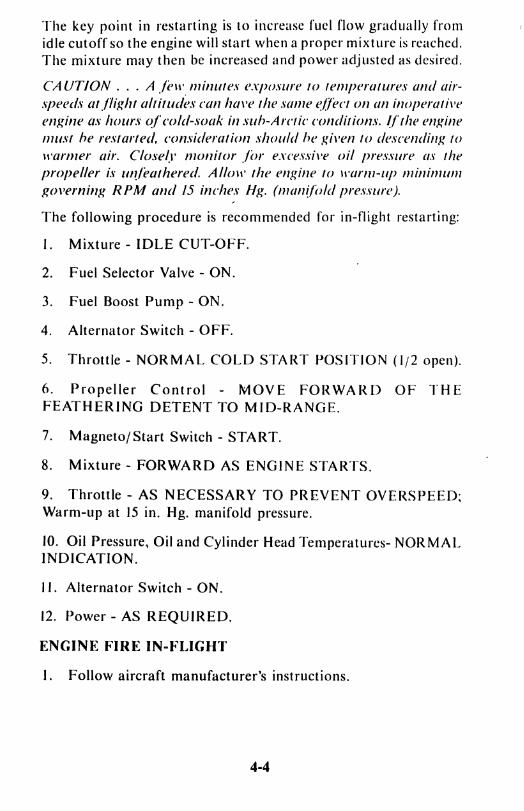
The key point in restarting is to increase fuel flow gradually from idle cutoffso the engine will start when a proper mixture is reached. The mixture may then be increased and power adjusted as desired.
CAUTION . .. A felt·, minllfes exposure to temperatures and air.\peeds arflif(ht altitudes can/ul\'e the same l~/lect on an inoperatil'e enf(ine as hours ofcold-.wak in suh-Arctic conditions. (lthe ellf(ine must he restarted. consideration should he f(i\'en to descent/inf( /() warmer air. Close~1' monitor for excessive oil pressure liS the propeller is lII?leathered. AI/ow the enf(ine to lI'a/"lll-Up minimum f(o\'erninf( RPM {llld 15 inches Hf(. (m(/n(lo/d pressure).
The following procedure is recommended for in-flight restarting:
I. Mixture - IDLE CUT-OFF.
2. Fuel Selector Valve - ON.
3. Fuel Boost Pump - ON.
4. Alternator Switch - OFF.
5. Throttle - NORMAL COLD START POSITION (1/2 open).
6. Propeller Control - MOV E FORWA R [) OF TH E FEATHERING DETENT TO MID-RANGE.
7. Magneto/Start Switch - START.
8. Mixture - FORWARD AS ENGINE STARTS.
9. Throttle - AS NECESSARY TO PREVENT OVERSPEED; Warm-up at 15 in. Hg. manifold pressure.
10. Oil Pressure, Oil and Cylinder Head Temperatures- NORMAL INDICATION.
II. Alternator Switch - ON.
12. Power - AS REQUIRED.
ENGINE FIRE IN-FLIGHT
I. Follow aircraft manufacturer's instructions.
4-4

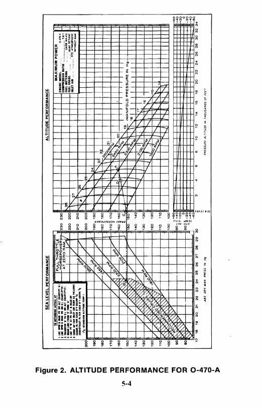
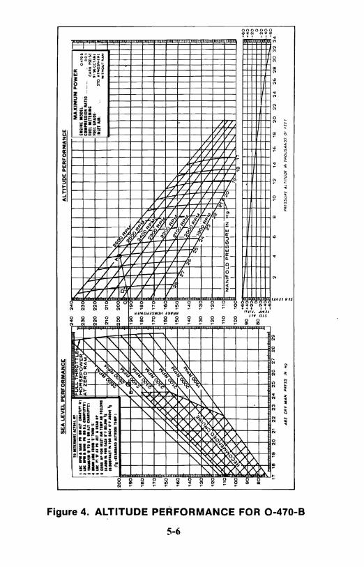
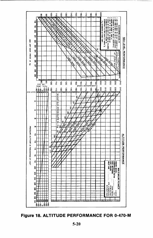
SECTION V
ENGINE PERFORMANCE AND CRUISE CONTROL
The performance curves in this section are provided as a general reference in establishing power conditions for takeoff, climb and cruise operation. Refer to aircraft manufacturer's flight manual for recommended power settings and tabular climb and cruise data.
CRUISE CONTROL BY PERFORMANCE CURVE'
I. Set manifold pressure and RPM at cruise power selected.
2. To determine actual horsepower, employ the following procedure:
(a) Locate RPM and manifold pressure on altitude curve (point "A").
(b) Locate RPM and manifold pressure on sea level curve (point "B").
(c) Transfer "B" to sea level on altitude curve (point "C").
(d) Draw line from "c" through "A".
(e) Locate point liD" at pressure altitude and read horsepower.
(f) Correct horsepower for inlet air temperature as follows:
(I) Add 1% for each J00F. below TS.
(2) Subtract 1% for each lO°F. above TS.
(TS = Standard Altitude Temperature)
3. Adjust mixture to provide fuel flow for actual horsepower according to applicable fuel flow vs. brake horsepower curve.
5-1

CAUTION . .. When increasing power, enrich mixllIre, advallce RPM and ac(just throttle in that order. When reducing pOll'er. retard throttle, then a((just RPM and mixture.
NOTE ... It may be necessary to make minor readjustments to manifold pressure and mixture setting after changing RPM.
CRUISE CONTROL BY E.G.T.
If an exhaust gas temperature indicator is used as an aid to leaning, proceed as follows: -
I. Adjust manifold pressure and RPM for desired cruise setting.
2. Slowly move mixture control toward "lean" while observing E.G.T. gauge. Note position on the instrument where the needle "peaks" or starts to drop as mixture is leaned further.
3. At cruise settings between 65% and 75% advance mixture control toward "rich" until E.G.T. is 25° F. colder than peak. At cruise setting below 65% engine may be operated at peak EGT.
CA UTION ... Do not attempt to a{(just mixture hy lise of EGT al
setting ahove 75% ofmaximwn power. A Iso, rememher thaI engine power will change with amhient condilions. Challges in altitude or outside air temperature will require ac(justments ill mani/'old pressure antlfue/flow.
5-2

SEA LEVEL PERFORMANCE CURVES
----------1 ,
.,. t 29 :': VI 28 J;
;;: <l. 27 <: « ~ 26 >-0:: Cl 25 V) en « 24
23
V)
<: 860 .... ~ .55
ENGINE MOOEl COMPRESSION RATIO FUEl METERING FUEL GRAOE INLET AIR
(1·470 A 1.0.1
CA~B. MA·4 5 8081 OCTANE
STD. AIMOSPHERE WITHOUT RAM
FULL THROTTLE
I PROP LOAD V
/ ./ V
/ /J V
V / / V 1/ /
FULL THROTTLV j
V / PROP LOAD
1/ V
/ /
/
/ FULL THROTTLE
- ,-~OPLOAD
2000 2200 2400 2600 2800 ENGINE RPM
240
230
220 '" ...
210~ "'-
200~ a :t:
190 ~ « 0::
180 en
170
160
150
140
130
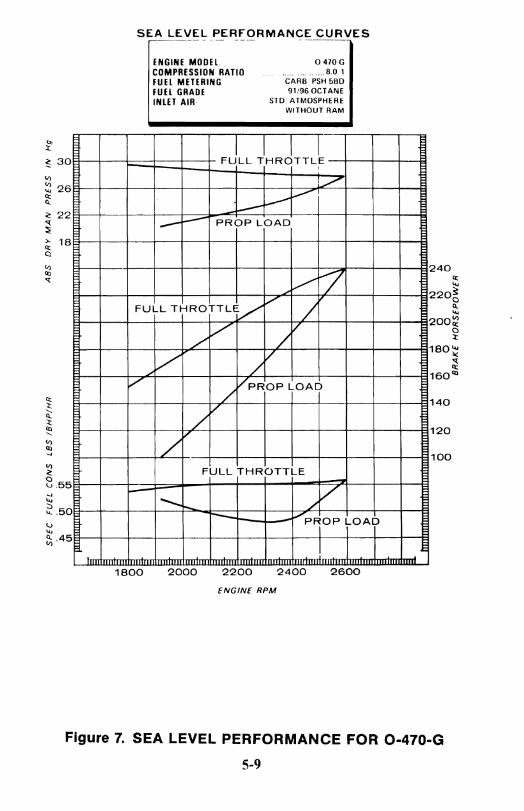
Figure 1. SEA LEVEL PERFORMANCE FOR 0-470-A
5-3
IJI
I ...
"T1
CQ c ii1 N :r> -!:i =i
c: c m
'tJ m
:ll
'TI o :ll 3:
:r>
Z o m
"T1 o :ll o I J:Io
...... o I :r>
SE
A L
EV
EL
PE
RF
OR
MA
NC
E
AL
TIT
UD
E P
ER
FO
RM
AN
CE
TI
1fT, ..
.. , ACT
1IA~
iii'
1 1
Lot ..
....
.. ,
. '.
All
C".
ltTlp
t'''')
F
UL
.L T
HR
OT
TL
E
MA
XIM
UM
PO
WE
R
2 LI
C ..... a
u P
I .. U
C
tlAlfI
PT
T,
-H
OR
SE
PO
WE
R !=
;a-2
30
2
30
£_
CII
E M
OD
EL
".....
0,
"70
A
:I tu
IItft.
· .. T
lU I
I A
ll , .
... 1'
I"·c·)
A
T Z
ER
O R
AM
... l/
2
CO
MPl
fSSI
Oll
Utt
iD
......
.. _ ...
......
......
.....
7.0:1
• IU
W ...
... n
'C
' JIM
....
/1
FU
EL .
ET
la.I
',
....
-..
CA
Rli.
li0ii .
.....
S •
LIC
" ..
... T
" a
n ..
. 1&1..
.. V
2
20
:2
20
\ ~
'UlL
ClA
DE.
. .
......
.. SO
fS' O
CTAN
E •
CfI
II .
, '" "
U1
_ T
I., A
I fO
UOW
S 2
7
11
m A
lii·
. .
STD
. ATM
OSII"
H£Rf
la
lAN
",'
H lA
aI", II
l"'S
W
ITHO
UT R
AM
" ..
... 1
'UC
1" ,'
1 lA
C. ,·
f A.aV
I Is
Lq
'~
I ;;I
' 2
10
2
10
'""
'l ~
,26
I'
s ·I1
A11
0.U
IO a
nlT
UI.
TIM
' I
• ..A
V
~
'-....
20
0
~/
V
20
0
20
0
2
r ~'
'" "-
10
0
q '/
1
90
1
90
l
........
24
/.,0
0("/
/V
...."
i' 2
J I
18
0
DO
)/1
1
60
1
80
I -
........
23
2"
V
I.
/
'-.
K<;-":
1
70
/
~q~/
17
0
17
0
I'
I ~'i> 2
1
1/ ~ ~ q~V
r--....
'"
A
~T;
'I,.
16
0
I /
r-.,:,' ~
0:'
.«''/
1
6"
160
. D
I ~0
'i>
·20
1/
-11\
9'
__ '!.Z
__
c --~ ~
l'-J~ I
'-19
1!
S0
VI-«~R<S
V
1/
15
0
150
r---.
~.<l
f
• ..,A
NIF
OL
O P
RE
SS
UR
E I
N.
Hg
I~
1
40
V
. -<
'-'-~
140
14
0
'"
1 ~..,
'\. "d
,'8
I
I I Iii I
I I
I
I T11
A~-0~,~V
v .........
K'''o
I I'-.
,,'7
I II
I 1
30
V
i ..<
:1-..',,
:<""
q....
130
13
0
I r
120
I7
f7
. ~f\:
ciA
r-:fO
1
20
1
20
-....
J. 7
0 ,r
-~
'-III
lA',
~:y <
. ,-:"
'~r
rY ~...,
N
16
v K
"kY
' ~?,,~
V
~...
, ~
t--~~
11111
110 l<
0~ ..
~~"-..
.'<.,;
y 11
0 11
0 .
III
10
0 l?
?l'1:6
"'-!'~
~":V
; 1
00
1
00
I
'N
~t--, ~N
111I
: ~~
>"
: ~ 1
1111
1111
1111
1111
11
1_
I HL~:~
1
7
18
1
9
",v
"'1
--~-
22
2
3
24
2
5
25
2
7
28
2
9
30
~
2 6
8 1
0
12
14
16
18
20
2
2
24
25
2
6
30
3
2 3
;60
AS
S
DR
Y M
AN
P
RE
SS
IN
H
g . ~
PR
ES
SU
RE
A
t rl
TU
DE
IN
T
I'fO
US
AN
DS
OF
FE
E 7

>-Q; Q
~ 20 <{
'" ~ 8·60 ... .., ~55
u :t .50 V)
SEA LEVEL PERFORMANCE CURVES
ENGINE MOOEl COMPRESSION RATIO fUEL METERING fUEl GRADE INLET AIR
FULL THROTTLE
-
./ V t......-V
./ FULL THROTTLE V . ./
/ ./
o 470B ........ 801
CARB PSD 5C 91:96 OCTANE
STD ATMOSPHERE WITHOUT RAM
"7 ./
V V PROP LOAD
I ~
V V J
/ /
/ [/r:' I I PROP LOAD
V /
./ V
P~i LOAD
---FULL THROTTLE
1800 2000 2200 2400 2600
ENGINE RPM
I
240 Q;
~ 2200
<l.
"" V)
200; 1:
180~
160
140
120
100
80
<{ Q; <Xl
Figure 3. SEA LEVEL PERFORMANCE FOR 0-470-8
5-5
"'" IE c A
LT
ITU
DE
PE
RF
OR
MA
NC
E
SE
A L
EV
EL
PE
RF
OR
MA
NC
E
... CD
~ ,. .~ =i c c m
."
m
(.II
:D
, • ="
"'" 0 :D
i:
,. z 0 m "'" 0 :D
0 • .1=
0
24
0
241_
r
to o
n ...
... -
..
FUL
L T
HR
OT
TL
E ..
.. ,
~
I Lt
C .
,., a
M P
I n
AlT
atilt'"
'." H
OR
SE
PO
WE
R ~
23
0
23
0 I r
'Ili
il.(
MD
DIl:
.
O~70
B
Z .. _
..
.. I
II U
Iol
CU
lT,,,
.. ',
!AT ZE
RO
RA
M",
V
N
.t
CD
_NES
Stal
l IIA
TIO
......
......
. .
.....
8.0 I
J _
.1
'r "
I L
I. A
ll Cl
WlT
I"'C'
l 1
/ fa
ll M
nEII
II'
CARa
PSD
!Ie
• ... U
Il fl. 'C
' 1U
I 'J
' 2
20
2
20
fU
EL
;RlD
I.
" '9
6 O
CT A
Ni
, lI
C "
"'I
T P
I at
, 1
Il0
l..
A<'rY
V V
f".
.. ~
1h.
'.LEt
All:
.
. ,S
lD A
TMQS
PHER
l ·:'''.:==~~::'~lfDUOWl
f.: ~
210
210 r
'"' ~"
w,TMO
UTRA
MIJI
, ....
....
....
....
....
....
... '
. feW
tl7
VI
.... 1'0
..."
"-I'.
. 11
1 11
1 ."
UD
I ••• LT
It_1I
TII
II' t
~ V
.D: 9
"" 1
/ 2
00
2
00
r ""
' t--..
. I· A
l "'
20
0
~~Wf7
C~ _
<"
"" ['.
,f'-~ .....
190
V
B
iB .~
""/ 1
~
190 ~
190
I"
I'-!?
O"i
.. 'Ii
teo
'V 1
,/
~ I'.
f'.
.?
~ ..
. ""
1BO
/
17
O'3
IW
[7
1BO
~ 1
BO
5eo ~ "-
vj.o
q,~~ ~~.
il: t'-
r-...
? !!' ..
.. ,.
, , L
. '1
-7 t
eo
'./
17
0"
170
~9i>
[I
"
I I
I t7~~
q,,yl.
.v /
~ t--
~~" :'<
t-...
'50
~
7IO
Yf
./
'80::;
160
....
... ~~ t-.
.........
N
VJ~I
'\
rf.'o'
F k"
"/ ./
1!s
0~ '50"~
:-..,
;;, *
'l ~
V~~ '"
~v:~~,"".//
.. ..
~~ "'~~"
'4N
" .
'40
17~ I
X K
~.
.II V
~
'40
'4
0
6' "'1
1-'i%..
.,. ... 1J'
I'-~. t'-
'30
~[
XI )( ... ~
Y
,JiP 1
'30
'3
0
~.:~~...
t'-."
" V~ :>
>-',,1
<K:
V
; ~L
i'-~
t'-t"t
---'2
0 ~[Q~ .. ~ C5
<rt :::
::: r ..
~ r-..
f'..
" t'-
.~ ~ ~
110 ~@~~ ~
jAN
lrO
LC
PtE~S":RE ,'N
r.
17
"Or-
-..7~
I'-t'-.
I'-
['.
'~~~KV
-
-:;;i
111111
111111
1"1'11
Allm
lUI]
17
18
19
20
:21
2
2
23
2
4
25
2
6
'27
28
29
~
'2
4 6
e 10
1:
2 14
16
18
'2
0 2
2
24
26
2
8
30
3
2
34
MA
XIM
UM
PO
WE
R
'70
1601
......
...es
D
R't'
MA
N
PR
ES
S
IN
Hg
-P
RE
SS
UR
E A
t T
lTU
Dl
If¥
TH
OU
SA
foD
S
01
1
((7
~
Q
::; I a:J

0> :t ~ 30 V)
~ 29 Il:: Q
25
24
23
'" ~ 865 -J
'" ~.60 '->
'" e;55
SEA LEVEL PERFORMANCE CURVES
ENGINE MODEL COMPRESSION RATIO FUEL METERING FUEL GRADE INLET AIR
FULL THROTTLE
0·470·( ............ 7.0.1
. CARB. PSD·5C 80:87 OCT ANE
STD. ATMOSPHERE W1THOUT RAM
I I
I--- i-- -r-- I--r---,
/ /
PROP LOAD
V /1
V / VI V v II /
/ / FULL THROTTLV-/
/ /
V V
/ / PROP LOAD
V
/ I FULL THROTTLE
1/ -9Ropho
2000 2200 2400 2600 2800
ENGINE RPM
1 i
I
230", ... ~
2200 0.. ... '" 210~ :t
'" 200><
190
180
170
160
150
140
« '" '"
Figure 5. SEA LEVEL PERFORMANCE FOR 0-470-E
5-7

"T1
cO'
t: ;;; ~ » !:f ~
12
c:
0 m " m
'JI
::D
, QC
"T1
0 ::D
== » z 0 m
"T1
0 ::D
SE
A L
EV
EL
PE
RF
OR
MA
NC
E
i: TO
."' .
... ,
ACT
U'"
••
, LO
t .,
. ..
...
,. 0
1 A
U C
UII
YI"
"'J
F
UL
L T
HR
OT
TL
E hi
I L
it .
....
...
PI '
1',
CllA
lIT
ln'l'
l J
TU
nn
Jl '.
10
S I
01 a
u C
UII
11"'C
') H
OR
SE
PO
WE
R
!--
23
..
....
. U
II f
lO.
'c' T
IMIU
'.'
A
TZ
EfO
,A
M
I·'ot" .
........
........
•
Cal
l. ,
,, ...
'IU
T a
u, U
.' AS
FOUO
WS
~V \
2
2
latA
" "
'Oil
IA
CII
•• ,
.lLO
W "
,I
"»""
CT
"
fall
lAC"
."
J al
aVI
Is ~
210
! tT
s 'S
UI.
aIU
I A
nnul
i ..
...
I
"ef/
~
20C
90
V
~1-
-1
90
SO
I~
V
1/
k*.T
-1S
0
70
1
70
60
.~ /1
Yr
/
ASX
.t'
16
0
!SO
/ I~
~ __
::ti
15
0
40
/
Kf0l
'~
~f<0 ~ ~
~t-
14
0
30
/
./'
13
0
20
f-9<
(0b<
",,"'-[j
' V
I,
~
~ ~ ~~
'" ~ V
,/
12
0
10
~~ O
M I~
~~ ':l
"0
C
R
V
00
1
00
~ ~ ?(
-0: y
/'
90
9
0
SO
Y. ,'" ~y
,,"'" "" y
eo ~
0 18
,9
2
0
21
22
2
3
24
2
5
26
2
7
28
2
9
30
I ~
......
"IS
D
In'
MA
I-t
PR
ES
S
IN
NrJ
C I m
AL
TIT
UD
E P
ER
FD
RM
AN
C_
E
MA
XIM
UM
PO
WE
R
E."
IE M
ODEL
. 2
30
C
OII
I,.n
Slo
l IlA
TlO
,
I I
I FU
ll II
IfT
tI"I
' 2
8
fun
GR
AD
l
2:20
\'
~7 '1
IlL
" A
ll
21
0
\ \ ,t
2
00
2
5
0<47
0.£
.. 7
01
C
AR
B
!"S
o ~
so 8
1 O
C'U
,NE
STO
ATM
OSP
HER
E W
ITH
OU
T R
AM
90
I"-
. ~ 2
4
•
\"'--
. ~
2:
SO
1\
1\ •
l"--..
'I \
I \ ~2
MA
NIF
OL
D P
RE
SS
UR
E IN
H
g
17
0
i"-
1 \
,2
' ,
N
t'...'
16
0
'q ~
50
....
.. O
J-.
..,A
~",
__ c
....
.;"
,,~~ \~ 18
'40
K
-:>!:l
S"?o
"
-l.
: r....
.. I ~O
o 'i''''.
... t'Z
00
.~"
N....~U~..
0 ~~
.il
I"-~ 7
,,1 1\ ~
r......
t'-.
I'h.
IE!
~ \
r-.... ~
"'t'-.
1::J
IE
13
0
12
0
"0
10
0
+<
+.
+. ,
~-'
~-, JI
I·IIII
IIIIII
III H
I HI 1.
11J111
[~ ...
:2 4
6 B
'0
12
14
1
6
'8
20
2
2
24
2
6
28
3
0
3:2
34
PIH
SS
ullt
At
TIT
uO
( ''''
TH
OU
SA
ND
S
01
1
([
1
III
::! 26 ~ C! 22 <{
~
~ 18 Cl
III C!
8.55
" '" ~ .50 u
'" 2i .45
SEA LEVEL PERFORMANCE CURVES r------.- _.- --- ._---
ENGINE MOOEl. o 470·G COMPRESSION RATIO ................ ..... 8.01 FUEl METERING CARB PSH 5BO
FUEl GRAOE 91!96 OCTANE
INLET AIR· STD. ATMOSPHERE WITHOUT RAM
FJLL JHRJTTL~ , .7 --V
:.----~ PROP LOAD
V 7 FULL THROTTLE/
,/ / ,/'
/ V
./
/' / /
,/ VPROPLOAD /
/ /
/V FULL THROTTLE
- V ~ ..... / -- V pROP LOAD
1800 2000 2200 2400 2600
ENGINE RPM
240 ~
'" 220~ o II.
'" 200~ o :t
1 80~
: 160Ql
140
120
100
Figure 7. SEA LEVEL PERFORMANCE FOR 0-470-G
5-9
."
cC
c:
SE
A L
EV
EL
PE
RF
OR
MA
NC
E
.. CD
TO I
nu
•• 11
&tt
l&&
. 'IP
!»
l> ~ ~ c: c m " m
Ul
::D
I ."
-:>
0 ::D
3:
l>
Z 0 m
."
0 ::D
22
.!,""
'""O~
1 la
C .
,.. M
Al.
N.
DI
All
CM
IITIP
T: ... ·
'· -
.I ut
e ...
. ,
....
, N,
DII
I.I.
cllA
ITl""
r, H
OR
SE
PO
WE
R
:I fa
UlF
ll '"
TO
I.L
•• A
li C
UII
lIPT
t)
AT
ZE
RO
,A
M
to IU
Ir 1
111
flO
M 'C
" ,.au
' .. -
IL
K" 'I
' AT
"'.A
Ll
11
1M
.'
l:~~
•
co ••
.• ,
fli
tlL
n ...
n .... fO
UO
WS,
rJ3
'tf: IA
tuD
"
fOI
fact
i; '"
' H
UM
"
IIt1
U"U
,CT
" ,.
1 IA
aC '"f
AtO
VI 's
.
W ~
~ ,
I'S o
STaI
IUI.
aL,
mtD
I n
., I
[7 ,
.~'6
~ :/
/ V
l~
r-
V.
Icfl/
~ /
/ vf
/~~ --
'zf.-+
j
V
V
o~
~ (/
. V·
. q;
A
~<:>
/ ~ -
V,V~ ~%.
~ /
:p
o ",~<,;.-...'
~,p;
,l' ,~il /
V
.~
,/"
;/
(j~""
r i./
o
. K·'~
V
" "
.. ' I
'.j V
· b'/
V )
",'.
20
0
18
16
14
'2
10
0
0 ."
y
I 18
"I
2
0
2 ~~
,,~
"4
2
5
26
2
7
28
2
9 ,
::.
....a
0 A
IS
DR
'" M
AN
P
RE
SS
IN
H
p
I C)
24
0
22
0 ~
200~
~ .. ,e
o III
:
--ai
160
140
12
0
24
0
22
0
20
0
18
0
~
16
0
14
0
12
0
AL
TIT
UD
E P
ER
FO
RM
AN
CE
MA
XIM
UM
PO
WE
R
II"I! U
DE
ll ..
......
.. 0-
470.
(;
J C
O.N
I"IO
IIA
TID
.....
...... _
......
......
.....
'.0
'1
FUEL
.n
Ew
ll;
CA
RB
!'$
H·s
eD
fU
EL G
RADE
: .. _
......
......
... , .
.... '1
1. OC
T "HE
~rr
.ILET
AIR
..
. ..
. "' S
TD.
A'M
O$I
"H£A
( W
ITH
OU
T A
jIW
26
N
~25
~
\ ~24
"'I r-..
.. ,,~~NIFILD, P
iES
SU
RE
IN
. H
t" "-
'" -A
~22
~ -~D
i"-N
Ln
I"-~ ~ 1
r--;>~ ~1
~~~i8
J.... J
\ i'~
;?oo
~ "
~~"~OO
I 'i>
", 1I
f
~ 'i'
~".,
":--
., \ '<
.'"
~
l' f'-"
\' N.
I'-. l' "
-
,{it
] EFmmnmtlittmull
lHll~
o ~
:2 4
6 8
10
12
14
16
18
2
0
22
2
4
26
2
8
30
3
2 3
04
~ P
RE
SS
UR
E
AL
TIT
UD
E
IN
TH
OU
SA
ND
S O
F F
ElT

NOTJ: This chart is for 70°F carburetor1slr te~peralul,e. For1every \O·F Increase
~ In carburetor inlet air temperature subtract 1.3 lb. of fuel 'rom curve. For every 10D F decrease In carburetor Inlel air lemperature add 1.3 Ibs. of ,uel to curvj'
I I I I I I I I I CHART INSTRUCTIONS:
1. Obtain 8clual Full Throltle RPM. ~ 2. Determine Fuel Flow for 100% maximum power by reading directly above aclual r-
maximum RPM point ,
~ EXAMPLE: Actual Full Throttle RPM 2700 Fuel Flow 143.-4 - 154.6 r-Aclual Full Throltle RPM 2600 Fuel Flow 138.04 - 1049.8
156 156 r--
15-4 - 154 r--I'\C,,~ I--I--
~ r-~ 152 I--
152 ~ ~ - .Ii
~ =-~ r-i 150 150 ~ 0
~ .... .... LL
148 -- 148 LL - 1-.... .... W
~r~ I--f-"" W
ir ::l LL
- I-W 146 -- 148 w .... - .... t: f.--- t: f-- I-~ 144 ........-. 144 ~-
1:
----1:
I- - l-
f--1-;1 142 142 g-i? \..ea"~ I---" LL
140 ~ 140 '--
f.----138 I-- 138-r--
2600 2700 I, Y 30 40 50 60 70
Y 90
I I I I I I ENGINE RPM FOR 100% POWER
I lfyLL THrOTT~E) I
Figure 9. FUEL FLOW LIMITS FOR 0-470-G
5-11

'" ~ 28
:l: C!·26 '{
~ :>. 24 ~ '" 22 "" '{
20
18
~ 8.60
~ .... . 55 U .... e; .50
SEA LEVEL PERFORMANCE CURVES
ENGINE MODEl: ..... .......... O·470·J COMPRESSION RATIO ............................. 7.0: 1 FUEl METERING: ........... . ..... CARB. MA·4·5 FUEL GRADE: .... :........... . ..... 80/87 OCTANE INLET AIR: ................... STD. ATMOSPHERE
WITHOUT RAM
FULL THROTTLE I-.
, 7 /~ROP LOAD
L /
-7
V "../' r-- / ./ /" /
./ V /V V V
V ~ROPLOAD V / FULL THROTTLE
",V / V
/ V
FULL THROTTLE .... ,
r--r-- t....-" ~ PRPP lOA~
1800 2000 2200' 2400 2600 ENGINE RPM
240
220 It ....
200~ I\. ....
1 80 :Q o :t
160~ q: It
140""
120
100
80
Figure 10. SEA LEVEL PERFORMANCE FOR 0-470-J
5-12
-n
cQ
c S
EA
LE
VE
L P
ER
FO
RM
AN
CE
A
LT
ITU
DE
PE
RF
OR
MA
NC
E
... (1)
! ' .~ •
..:::~!::;:::::" ...
, F
UL
L T
HR
OT
TL
E
.. .. » r- -I =t c: 0 m "
VI
m
I :z:J
-(.H
-n
0 :z:J
3: » z 0 m
-n
0 :z:J
Q
I 0l:Io
I ' ,~ .-.
-... ~
.. ,-""
'., I-
-H
OR
SEPO
WER
AT
: I
, ...
....
....
-.
10~.
Ofo
_\ T
e ..
.. ' "
','1: ,
•
('>10
...
. , ....... _
--, •• _
".
ZE
RO
RA
M
/ I
~ ,,~.,
'"
aT
...
... "
..
"'"
0'''
I' :;:~
\¥f~~~
3E.;~~
~~~~~:
'~ i/
l/ ~I
:
;.y V
1 \ : :
~v
./ h
V~"
V
\ ,
V VI
').~
j
V K
VI
/V
11 F,
1/
Kr£>
! -~..
., ~
j /
K [X
II 2
/' V
g
/.~ I"
) /'
V
.§ 5
1-~~~
~ ~
# ~
o~~'
?<
V
~ 1
-,,<:
-«.,0 ~~
KfX-
I"-I
/'
~ K
~ ~
! ~ IY
I
I .~'
18
20
22
24
26
28
230
I I
I I
i"-,
27
MA
NIF
OLO
PR
ESSU
RE
IN. H
G.
220
N'-.
,.j6
t-.l.
. II
11'
PRES
SUR
E A
LTIT
UD
E IN
T
HO
USA
ND
S·
Ff[
T
210
~
80
'"
100
90
I I
I I
I I
I I
I I
I I
I I
t I
I I
H-~
~=r"
i 22
00
~ '~II
I t Ili
llllll
! I [PH
_11U1
11I11
• ~
~ •
• •
• I
• to
11
12
13
M
,~
16
17
".
1'
1 10
7
' .. 2
2J
2.
r..
:l
6
" 1'
fI 1
t lO
31
31 l
l:W
A.8S
. D
RV
MA
Nif
OL
D P
RES
SUR
E IN
H
C
200
170 ·'i
I •
c 5
0-
40
30
20 \.
'0
80
.....
Q
I c...

Assuming: Carburelor Air T emperalure 60' F Carburelor Enlrance Pressure 5.8 in. H20 Dry Barometer Pressure 29.300 in. Hg
-
128 128 -Rich Limit -
- -~ 126 126 ~-:i - :i .... .... - -- 124 12' --3 Normal 3 0 0 -
~ -it 122 122 it-.... ....
I---~ 120 120 ~-"- Lean Limit
118 I 118 I--I
2550 250 2590 2810 2630 2650 2560 2580 .\. 2600 2620 2640
ENGINE'RPM
0
Figure 12. FUEL FLOW LIMITS FOR 0-470-J
5-14

~-~~~--~~-~-~------~----------
'" 30 :t
~ 28 II) II)
~ 26 <I.
~ 24 ~
~ 22 Q
.,; ~ 20
18
~.60 o u
~.55 II.
~.50
'"
SEA LEVEL PERFORMANCE CURVES
ENGINE MODEl: _ ......................... O·470·K. L COMPRESSION RATIO: ................................. 7.0:1 FUEL METERING: ........................... CARB. MA·4·5 FUEL GRADE: ................................ 80/87 OCTANE INLET AIR: ............................. STD. ATMOSPHERE
WITHOUT RAM
-- FULL THROTTLE .
--, . I //
.. "_.
PROP LOA~ / ~ . - t·
V ~~VV V ~ ~ V ~"'~ ~ O~ / ~-<,"<f-
~0"'''' ~ V /
VPROP LOAD
/ V
V CIro. FULL THROTTLE .........
I'---- I"-..... J .............. ~
~
----PROP LOAD
1800 2000 2200 2400 2600 ENGINE RPM
230
21011: ~
190~ ... '" II:
170~ ... 1 50~
~ 130
110
90
70
Figure 13. SEA LEVEL PERFORMANCE FOR 0-470-K & L
5·15

30
ci :r 28
! 12 26 w II: L
Z 24 ... ::E >-II:
22 D
:i ... 20
18
0: ~ .700 :z: I!! Ii .... .650 .. ~ U ... . 600 w :> .. U w .550
III
.500
SEALEVEL PERFORMANCE CURVES
ENGINE MOOEL, 0·470·5 !!a!f' 7110/74
MIN FUEL GRADE, 80187 COIAP. RATIO, 7,1
~, STD. ATMOSPHERE WITHOUT RAM
'.
--,/
,/
-......
1800
---r-- ~l~JTTlf
-/
~ / ~/
V ,,,,0' -- ~<\"\"~ / "\~q.0
/ ~" .... "
V f qq.Ql
/' /'
./ V
fULL THROTTLE .........
'-... ~}{O"'O -2000 2200
ENGINE RPM
2400
J V VI V
~ ......
2600
230
210
190 0:
~ 0 ~
170 .. 0: 0 l:
150 ~
" - .. 0: - III
130
110
90
70
Figure 14. SEA LEVEL PERFORMANCE FOR 0-470-R & S
5-16

0 oa a:: S
EA
LE
VE
L P
ER
FO
RM
AN
CE
A
LT
ITU
DE
PE
RF
OR
MA
NC
E
" IIT
' ... II AC
llAl lIP
1. Ltc
I .
.......... n
AlT
. e ..... ""·., FU
LL TH
RO
TT
LE
M
AX
IMU
M PO
WE
R
a. LIC. _
11
1M
. PI, II I.L CU
l'flnTJ
HO
RS
EP
OW
ER
,
EIIII. M
ODELz ......... ~ .. ~.M •••• _
... O
... 7Q.K. L. R
!::':t·~~~::! •. C
IIAI1I",C
1 A
TjE
RO
-RA
V'
23
0
23
0 ~
:::':.~::I~~~~~:==c.vtI.M!!~ IlK
."'"
AT fa. An .• IU
D If
I.! 2
20
2
20
fU
El CIADI= ·· ........ _ ............... _._""7 OCTANE • CO
llI ... 'H IIL
IT" 'D
IP AI fOllOW
S· 1
.tB7
2
8
.Im A
ll: ·······•···· ................. STD. ATMO$PHERE
:=:.:;-.~~ .. ~o:ra!:.,.'1 ~~./
2'1
0
21
0
'"
WITH
OU
T RAM
I ,r. ·IT
....... "W
I","
M' I
Jr it.y '" l\
" I I
I III 200
~
V' 200
20
0
I"
I~t '9
0
/ 'Ir/ I
'90
'90
I ,
1 '1 '8
0
/ V
~ .. V
,sJ 'so
"'. \
i'\ i'.2
2
_Ull!
/ hsP;;;"-
= t"--." r--.. I"
MA
NIF
OL
D P
RE
SS
UR
E IN
. Hg
• ~~~
A
~
B /1
V
,eo~ C
"
D ~
il' ~o
I I
I I I I I I I I I I I I IJlJ
Jj
V ~ \\ /
/' :~
r---.. r'--~
N ",
! II
1 III V
~' \ \ \}
i.~~ '150
'150 ,~
i'\ \ 1\ \ V
fI i7
i'..
f'.
, t-L
'40
V
IH
' 1\ \ f\)('
Y
q,rffl I"",
'40
'4
0
~
~~,... P
(\ f\ \ \LJI: \ V
1 .J
j,o" f'..
I ..... ['.."'<1
1'fe~~'15 '30V~\l)('lI\V
V
'30
'30
%_~,. ~
n'r
\\I'\\f\Y
/1
./
f'.~ ~;t, ["':It ~
;
'20
~Effg:u'i'ir\~~ I ~
r
'20
'2
0
~!io.. ~
I' " ,~
110 i\\rsA
'.\ 'V
~~ 110
110 ~~
II...... 1-....1 I"~
'00
[" r\ \1\ \
../
'00
'0
0
• ......,. II
t'--I ... '"
N
~
.lJJ1I ~N~
V
~
90
b> 9
0
+4 +
40 ..::+
2
+2
0
.., ~
0 ·8
0
V
80
" -2
.
-20
~~
~
--8
0
'8
,e
20 21
22 23
2.
2!5 215
27 28
2e
~
2 •
15 8
'0
'2
'4
'15 '8
2
0
22 2
4
211 28
30
32 34
=: ~
PR
ESSU
RE
At 11TU
DI IN
TH
OU
SAN
DS O
F F
ElT
'70
'150
'50
A'S
D
lfY M
AN
~IIISS
IN
H,
...[ ~
• ·0
.... '1;1' • 0
,
a:: 0 u. w
0 Z c( ::!
r--a:: -
I
0 II')
"-a:: w
a.. w
C
::l t-i= -I
c(
an .... Q)
... :::s a» -
. u.
1:1--1--1- Correcllon For Vapor Pressure: -_+--+-_+-_+-_+-_1_-_1_--13 For every .1 'in. Hg Vapor pressure below .500 in. Hg, add .4 Ibs. per hour.
1:1----11--1--+ For every .1 In. Hg Vapor pressure above .500 in. Hg, subtract-l--+---I----t3 .4 Ibs. per hour. LIMITS" .. 5.5 Ibs. per hour (4%
- 140+-+-+_-+--j--I--I---+--+-+-+-+-+_-€l
_ 138+-+-+-+-+-+-+-+--' tfancS' Pf~ssure 31.0 in: H9_
G"bure~'~f:.:-- 'I .. _ 136+_+_+-+-+--,P.\)50 \\.I\8 __ r-- 30.0 in. HQ_ -~
f-~ 134 ___ ----~ _ 1---1-" 2~OJ9-: f-i 132+---c:b-'I'-=-+----+--+-OP-j=-=---j---+--+-+_-l---fj
<Ii --- ___ -- 280in Hg
~~ 13,~-_+~~~~-+-+-+_~~--F-~~-+-+_-+-I-§ ~ ---- __ - - 2~.O in. Lg
~b 128~-+_-~~~~~~-+_-+--d~_+-==F==r===~~
~ ------ -----~ 126-r-+~--+~-~--~~-+--+--+--+-+--I---I---+-~,
124 --
~ 122;--;---r--r-+--+-+-+-+--r--r-1---~~
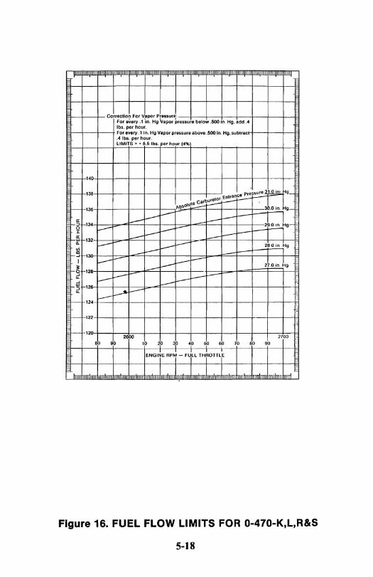
Figure 16. FUEL FLOW LIMITS FOR 0-470-K,L,R&S
5-18
'" '" '" lE
0
~ 25
~ :..
'" o ~ 20
"
~ o '-'.6 0 .... '" ~ .5 '-' '" e;.5
5
SEA LEVEL PERFORMANCE CURVES
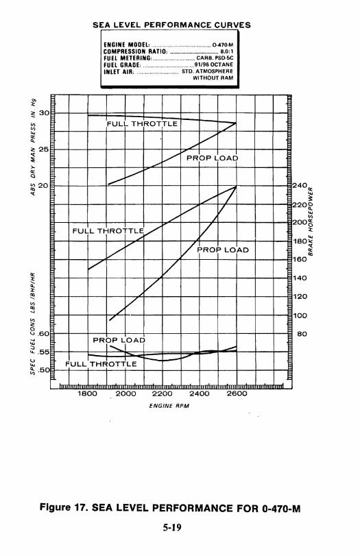
ENGINE MODEL: ..................................... O·470·M COMPRESSION RATIO: ................................ 8.0:1 FUEL METERING: ........................... CARB. PSD·5C FUEL GRADE: .. , .............................. 91/96 OCTANE INLET AIR: ........................... STD. ATMOSPHERE
WITHOUT RAM
FULL THROTTLE .7
./ V V PROP LOAD --, .......... V
./ F1 V V
/'" /.
FULL THROTTLE/ ./ V
V V
VPROP LOAD
./' / V
/ V
I"
PRF~JOAD --'-.
FULL THI~OTlLE ~
1800 2000 2200 2400 2600 ENGINE RPM
2
I'
2
1
1
1
1
1
40",
~ 20 0
~ '" OO~ :t
'" 80ll{ ~ Ql
60
40
20
00
80
Figure 17. SEA LEVEL PERFORMANCE FOR 0-470-M
5-19
~-.r'-
I I
:E I S
EA
LE
VE
L P
ER
FO
RM
AN
CE
A~S
QR
Y M
AN
P
RE
SS
IN
H
g
2
r-
TO an
UM
'"1
"tTUA~-.!! F
UL
L. T
HR
OT
TL
E t':i
! ~ i~~ :::: ::: ;: g: :~T cc:,.~~~~~.~·1 HORSEPOW~
11 'IA
.IIS,..
" TO S L
0 .. AU
'",..,ITI""C', A
TZ
ER
f ~A
VI
: 4 D ..... U
II( fliO. 'C
' '""" .....
! t LOC
,., '0' AT ,. AU
I
IUA
O "
,
~l7 1/
I' C
Olli
", FO
il IIIUT
A'" T
U., A
S FO
llOW
S ( ... ~
oo ~ fO
il fAeM
"f IU
OW
's
r-~~v
I ,I'IU
IUI"
""
, 1011 lACM
C' f ""on TS V
I'S
'SY .... O
... IID A
(fITU
Df filii' I
/~/
9 9
0
V /~/
V~ V~~~~
V
70
Vl0:RS
lJrl~9 V
6
0
V~~
lJP1~« V
50
/~~K)K2 V~~.j/
40
/~~~~~
#-o~ /
,~
30
V~R)<~~ojls~v V
2°~~~i~~UV
10
:?:~~~!»
00
k;~1:Y'
80~
~~
--'--_
__
_ .J.
18
1
9
20
21
22
2
3
24
2
5
26
2
7
28
2
9
"''-
I I I
Ulo
le. r-c,n
r vn
mA
r. .... 1I:.
24
0 ~
MA
XIM
UM
PO
WE
R
23
0
E"'lflE
MO
DEl: ".
0·0470M r-
"\ .1 C
OM
PRESSIO
N RATIO
· ............ " ....... , ...
8 a 1 fU
n IIE
TU
UIG
· C
AR
8 PSO·SC 2
20
FU
El CiRADE:
.... ' ..
. 91196OC
TAN
E I-
" "1
", "
IJUET AIR: ............... STDw~;~g~::
21
0 t'-.,
" [';:...
20
0
l'-. A
C ~ r-"
--:--.. 1'1\.
19
0
" i':--H"\~
18
0 t'-..
"'oS: !'\>
:-.... i' N'~
17
0
v:O~ ~~
" ~~ ~
16
0
15
0
_ 28.......
....... ~~~ I-t:-...
27
i' ........
~o!:J !'\> ... ~ t-: ['\NI"
,~
~
~
2~' ~~
:--.. i':}'
13
0
~.()
2j 23'€eO~
t'-., '-'I ':'--:t'-.
12
0
~!i''''!Ii M
AN
IFO
LD
PReSSU~E I~. ;: ~"
",,-:-..t'-. 1
10
1
I I
201~~ t'-":-....'-1'
10
0
__
__
24
0
23
0
22
0
21
0
20
0
19'0·
18
0
17
0
16
0
15
0
14
0
13
0
12
0
110
10
0
18
1
7
~IIIIIIIIIIIIIIIII WI wtlUt1ll~
§ 2
4 6
8 1
0
1'2 1
4
16
1
8
'20 '2'2
'24 2
6
28
3
0
32
3
4
... P
RE
SS
UR
E
AL T
ITU
DE
IN
TH
OU
SA
ND
S O
F F
EE
T
90
80~
~
C
,.... 'lit I
C
a:: 0 LL.
W
0 Z
<
:E a:: 0 =
LL. N
a::
I II')
W
n. w
Q
:l i-i= ...I <
cO ,... G» .. ::;, en u::

NOTE. This chari IS for 70° F carburetor air temperature. For every 10e F increase in carburelor inlel temperature subtrac1 1.0 lb. of fuel from curve.
I I I I I I I I " CHAAT INSTRUCTIONS:
1. Obtain actual Full Throllie APM.
~·ir~~:~;~~~~!~~lt~~~~~:i~~: ~~~~~~towr by rrding
EXAMPLE: Actual full Throllis RPM 2700 fuel Flow 128.0 . 138.8 AClual Full· Throttle RPM 2600 Fuel· Flow 123.0 ·132.6
-
140 140 -
138 ,....-
138 -.tt\"\\ V -- -
I--r-f 136 ~~\ 136 ~ J!i -- 1i
I--r-=! 134 134 ,:L s:
V -- :.--- s: g -- g
I--r-~ 132 :--- 132 "" ~,~
-' w W :J . ir
I--r-"" 130 130 OJ ----- OJ
r-~ -' -- l-
I-- 128 128 I---- 0
II: --- a: :t --- :t I-
.(1"\\\ l-
I--r-j 126 ~~
126 j-:J --- :> "" "" 124 --- 124 I--
I--122 122 I--
2600 2700
't Y 30 40 50 60 70
Y 9t I I I I I ENGINE RPM FOR 100% POWER
(FiLL TH1AOTTiEI
Figure 19. FUEL FLOW LIMITS FOR 0-470-M
5-21
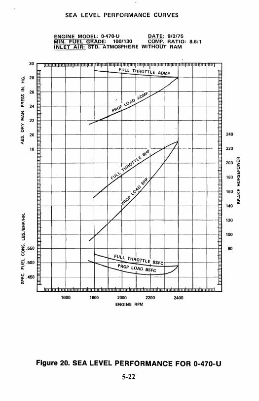
ci :I:
~ l:l w a: .. Z <l: ::;:
>-a: 0
gi <l:
a: :I: ~ :I: ~ gi -'
30
28
26
24
22
20
18
~ .550 8 -' ~ .500 IL
&i.450 ll;
SEA LEVEL PERFORMANCE CURVES
ENGINE MODEL: 0-470-U DATE: 9/2/15 MIN. FUEL GRADE: 100/130 COMPo RATIO: 8.6: 1 INLET AIR: STD. ATMOSPHERE WITHOUT RAM
FULL THROTTLE A01MP --
./ V
~ V
, 0",0 ~ V
--~./ .... -- I------- -- ---_. --
t9 _ .. - ---- -------- ----7 ~~~
-- -- ~ I----- 1--1----1--- 0.... - 1--7 f---- ---
~ vvv ....
V <Q~ i---1---- --1--- ./ -- ----vo~ --- ---- ----_. ----- -_. -_.-v
0/ </.Q'
/v . - ---- _ .....
--
/ /
.... r--~lT HROTTlf: BSFC ~ ~~OAO BSFC ./
1600 1800 2000 2200 2400 ENGINE RPM
Figure 20. SEALEVEL PERFORMANCE FOR 0-470-U
5-22
240
220
a: 200 w
;t 0 .. w
180 (I) a: 0 :I:
160 w " <l: a: III
140
120
100
80

~ f;:."l\'~:0 ;:s;~~ row .... ~ ..... · -. '.
Ii .!Ir"" ;oK ~ >(. ~ ~ ~ I>". .- i i: ~ili! II ~ ~ ~ ?\. ~ ~~ i ;;Fi!;i
~ ~ ~,~ ~ J! ir;'t;JJ
!:I ~ I!~:!=~: -..:;: "<\i~. f.Q ~ ~ ~ i '(WII'
II . J'-'- jj~ '\ '\ "'<; ~ ~ ~ ~ -II
\. '\ '\ I'\.. 'i."-" t:
\.~ " f\..: '\: "" ~i1! III !~ f-III
\~ ,,'\. l"'~ : ~ ~~ ~ It '\ R ",'\: '" f-
II ""- r;;
'\. '\ :1\. 1""- '" ~ III \i ~ 1\ -III ,
II
II II II ii II iii ii ii i i Iii i i II ii II R ~ .... ,"u. , .. -,n.. BRAKEI HORSEPOWER
= ii ii i fi i !~ i i II !:I II II • H' iii i .. 0 0 ,
· ·
-· - --- - .. -- --I
· f7 - J - II 7 · J- f-i- I-:t ~. ~ I'--
7 I ./
17 1/ V
i! • II "7 7 I /
-; 71Z f7 II 'I
'-1 I : , ~ . a. IZ ~~~
• • ~
• I
• • • .. • • • ~
• • •
17
lU.iii
/ :z:z I- IY. / ~
II -I. LL k: --- . :-L :R V IL-1-7, po
~~ 7 _IF r7 17...1
v L.L. 1-1' r.e: v~ -/ -"""' 1'--7 ~
f7[l ~~ ~ 7J7c ,. I V 7 ~
I V ~ 1/,/ II:
~ ~ •
en m ~ r-~ m r-"'0 m :u "11 o :u
~ z n m
Figure 21. ALTITUDE PERFORMANCE FOR 0-470-U
5-23
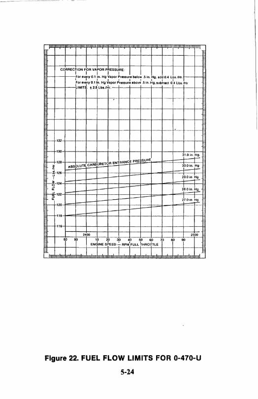
CORRECTION FOR VAPOR PRESSURE: I I I I I For every 0.1 In. Hg Vapor Pressure below .5 in. Hg. add 0." Lbs.lHr. I f I I I I I I I I For every 0.1 In. Hg Vapor Pressure above.5 in. Hg, subtract 0.4 lbs IHr I I 1 , LIMITS: t 2.5 Lb • .lHr.
,
, >-- 132
e- 130
SURE
31.0in.~
- 128 ABSOLUTE CARBURETOR ENTR"'NCE PR
~ 3rOin~ --!-126
"I 29.0 in H.!.
-~-124 -rt dao in~.!!:.
-¢-122 :>
J700n ~g ... . ~
- 120 -
I-- 118
I-- 116
2400 2500
T i 10 20 30 40 50 60 70
Y i d I I I I I r EN INE SPEED - RPM FULL THROTTLE
Figure 22. FUEL FLOW LIMITS FOR 0-470-U
5-24
SECTION VI
ABNORMAL ENVIRONMENTAL CONDITIONS
The following adverse conditions should be given special attention. They are: Cold Weather Operation, Hot Weather Operation and High Altitude Ground Operation. The information that follows may be helpful to the operator in obtaining satisfactory engine performance while operating in these conditions.
COLD WEATHER OPERATION (Ambient Temperature Below Freezing)
NOTE ... Prior to operation and/or storage in cold weather, assure engine oil viscosity is SAE 30 or SAE lOW30. In the event of tem-perorary cold weather operation, not justifying an oil change, consideration should be given to hangaring the aircraft between flights.
Engine starting during extremely cold weather is generally more difficult than during temperate conditions. Cold soaking causes the oil to become heavier (more viscous), making it more difficult for the battery to turn the engine over. This resu'lts in a slow cranking speed and an abnormal drain on the battery capacity. At low tem-peratures, gasoline does not vaporize readily, further complicating the starting problem.
False starting (failure to continue running after starting) often results in the formation of moisture on the spark plugs due to con-densation. This moisture can freeze and must be eliminated, either by applying heat to the engine or removing and cleaning the plugs.
Preheating
The use of preheat and auxiliary power (battery cart) will facilitate starting during cold weather. This procedure is recommended anytime the temperature falls below ,200 F. and the aircraft has been cold soaked in excess of two hours. Successful starts without these aids can be expected at temperatures below normal, provided the aircraft battery is in good condition and the ignition and fuel systems are properly maintained.
6-1
-- - 1
The following procedures are recommended for preheating, start-ing, warm-up, run-up and takeoff.
I. Select a high volume hot air heater. Small electric heaters which are inserted into cowling "bug eye" do not appreciably warm the oil and may result in superficial preheating. .
WARNING ..• Superficial application ofpreheattoacold-soaked engine can have disastrous results.
A minimum of preheat application may warm the engine enough to permit starting but wiH not de-congeal oil in the sump, lines, cooler, filter, etc. Typically, heat is applied to the upper portion of the engine for a few minutes after which the engine is started and normal operation is commenced. The operator may be given a false sense of security by indications of oil and cylinder temperatures as a result of preheat. Extremely hot air flowing over the cylinders and oil temperature thermocouples may lead one to believe the engine is quite warm; however, oil in the sump and filter are relatively remote and will not warm as rapidly as a cylinder, for example. even when heat is applied directly.
Oil lines are usually "lagged" with material which does an excellent job of insulating. Congealed oil in such lines may require con-siderable preheat. The engine may start and apparently run satis-factorily. but can be damaged from lack of lubrication due to congealed oil in various,parts of the system. The amount of damage will vary and may not become evident for many hours. On the other hand, the engine may be severely damaged and could fail shortly following application of high power. Improper or insufficient application of preheat and the resulting oil and cylinder tempera-ture indications may encourage the pilot to expedite his ground operation and commence a takeoff prematurely. This procedure only compounds an already bad situation.
Proper procedures require thorough application of preheat to all parts of the engine. Hot air should be applied directly to tne oil sump and external oil lines as well as the cylinders. air intake and oil cooler. Excessively hot air can damage non-metallic components such as seals, hoses and drive belts, so do not attempt to hasten the preheat process.
6·2
Before starting is attempted, turn the engine by hand or starter until it rotates freely. After starting, observe carefully for high or low oil pressure and continue the warm-up until the engine operates smoothly and all controls can be moved freely. Do not close the cowl flaps to facilitate warm-up as hot spots may develop and damage ignition wiring and other components.
2. Hot air should be applied primarily to the oil sump and filter area. The oil drain plug door or panel may provide access to these areas. Continue to apply heat for 15 to 30 minutes and turn the propeller, by hand, through 6 or 8 revolutions at 5 to 10 minute intervals.
3. Periodically feel the top of the engine and, when some warmth is noted, apply heat directly to the upper portion of the engine for approximately five minutes. This will provide sufficient heating of the cylinders and fuel lines to promote better vaporization for starting. If enough heater hoses are available, continue heating the sump area. Otherwise, it will suffice to transfer the source of heat from the sump to the upper part of the engine.
4. Start the engine immediately after completion of the preheating process. Since the engine temperature will be above 32° F., use the normal starting procedure.
NOTE ... Since the oil in the oil pressure gauge line may be con-gealed, as much as 60 seconds may elapse before oil pressure is indicated. If oil pressure is not indicated within one minute, shut the engine down and determine the cause.
5. Operate the engine at 1000 RPM until some oil temperature is indicated. Monitor oil pressure closely during this time and be alert for a sudden increase or decrease. Retard throttles, if necessary, to maintain oil pressure below 100 p.s.i. If oil pressure drops suddenly to less than 30 p.s.i., shut down the engine and inspect the lubrica-tion system. If no damage or leaks are noted, preheat the engine for an additional 10 to 15 minutes before restarting.
6-3

6. Before takeoff, run up the engine to 1700 RPM. If necessary, approach this RPM in increments to prevent oil pressure from exceeding 100 p.s.i. At 1700 RPM, adjust the propeller control to "Full Decrease RPM" until minimum governing RPM is observed, then return the control to "Full Increase RPM ". Repeat this procedure three or four times to circulate warm oil into the propeller dome. If the aircraft manufacturer recommends checking the propeller feathering system, move the control to the "Feather" position but do not allow the R PM to drop more than 300 below minimum governing speed.,
NOTE ... Continually monitor oil pressure during run-up.
7. Check magnetos in the normal manner. "
8. When the oil temperature has reached 100° F. and oil pressure does not exceed 80 p.s.i. at 1700 RPM, the engine has been warmed sufficiently to accept full rated power.
CAUTION . .. Do not close cowl [laps in an allempt to hasten engine warm-lip.
NOTE ... Fuel flow will likely be on the high limit; however, this is normal and desirable since the engine will be developing more horsepower at substandard ambient temperatures.
If preheat is not used, employ the following start procedures:
I. Fuel Selector - Main tank or as instructed by aircraft manu-facturer.
2. Battery Switch - On.
3. Mixture - Rich.
4. Throttle - Open.
5. Primer - Operate until fuel flow or fuel pressure shows maxi-mum reading.
6-4
_~~T_~ ___ ___ ~ __ ~~ __________ ~ ___ ~ __ ~ _______ -- -~---------.--- ----,. -- -"----- --_.- ~---~---------------,
6. Throttle - Positioned to approximate 1000-1200 RPM position.
7. Starter - Engage.
B. Primer - Operate as necessary to initiate firing. Continue to prime as necessary to sustain engine operation.
9. Throttle - Gradually retard to BOO-1000 RPM for warm-up.
Observe oil pressure for indication and warm-up engine at 1000 RPM. Ground operation and fun-up require no special techniques other than warming the engine sufficiently to maintain oil tem-perature and oil pressure within limits when full RPM is applied.
NOTE . . . Before applying power for takeoff, check that oil pressure, oil temperature and cylinder temperature are well within the normal operating range. When full power is applied for takeoff, insure that oil pressure is within limits and steady.
CAUTION . .. Any of the following engine reactions should be calise for concern. and are just((ication for aborting the takeoff.
a. Low, high or surging RPM.
b. Any oil pressure indication other than steady and within limits.
c. Engine roughness.
NOTE ... When flight into sub-cold temperatures is anticipated, the appropriate Pilot's Operating Handbook should be reviewed as to the proper use of oil cooler winter fronts. If they are not available, a strip of I" masking tape may be secured thru the center line length of the oil cooler to maintain adequate oil temperature and prevent oil cooler congealing.
6-5

HOT WEATHER OPERATION (Ambient Temperature in Excess of 90°F.)
CA UTION ... Whe,n operating in hot weather areas, he alert for higher than normal levels of dust, dirt or sand in the air. Inspect air filters frequent~l' and be prepared to clean or replace them (f necessary. Weather conditions can I(fi damaging levels (~fdllst and sand high above the ground. In the event the aircra/i .\"hould he .f70wn through such conditions, an oil change is recommended as soon as is practical. Do not intentiona/fl' operate the engines in dust and/or sand storms. The use of dust COl'ers on the cowling will afford additional protection for a parked aircraft.
In-flight operation during hot weather usually presents no problem since ambient temperatures at flight altitudes are seldom high enough to overcome the cooling system used in modern aircraft design. There are, however, three areas of hot weather operation which will require special attention on the part of the operator. These are: Starting a hot engine, Ground operation under high ambient temperature conditions and Takeoff and initial c1imbout.
Engine Heat Soaking
After an engine is shutdown, the temperature of its various com-ponents will begin to stabilize; that is, the hotter parts such as cylinders and oil will cool, while other parts will begin to heat up due to lack of air flow, heat conduction, and heat radiation from those parts ofthe engine which are cooling. At some time period following engine shutdown, the entire unit will stabilize near the ambient temperature. This time period will be determined by temperature and wind conditions and may be as much as several hours. This heat soaking is generally at the worst from 30 minutes to one hour following shutdown. During this time, the fuel system will heat up causing the fuel in the pump and lines to "boil" or vaporize. During subsequent starting attempts, the fuel pump will initially be pump-ing some combination of fuel and fuel vapor. Until the entire fuel system becomes filled with liquid fuel, difficult starting and unstable engine operation may be experienced.
6-6
Another variable affecting this fuel vapor condition is the state of the fuel itself. Fresh fuel contains a concentration of volatile ingredients. The higher this concentration is, the more readily the fuel will vaporize and the more severe will be the problems associated with vapor in the fuel system. Time, heat or exposure to altitude will "age" aviation gasoline; that is, these volatile ingredi-ents tend to dissipate. This reduces the tendency of fuel to vaporize and, up to a point, will result in reduced starting problems associ-ated with fuel vapor. If the volatile condition reaches a low enough leyel, starting may become difficult due to poor vaporization, since the fuel must vaporize in order to combine with oxygen in the combustion process.
The operator, by being cognizant of these cond"itions, can take certain steps to cope with problems associated with hot weather! hot engine starting. The primary objective should be that of permitting the system to cool. Low power settings during the landing approach will allow some cooling prior to the next start attempt. Ground operation tends to heat up the engine, therefore minimizing this will be beneficial. Cowl flaps should be opened fully while taxiing. The aircraft should be parked so as to face into the wind to take advantage of the cooling effect. Ifrestarting is attempted in less than an hour following shutdown, vapor lock may be experienced.
Normal starting procedure should be used except that the throttle should be opened more while cranking. Under extreme temperature conditions, the "Hot Start Procedure" in Section III should be employed.
Ground Operation Under High Ambient Temperature Conditions. Oil and cylinder temperatures should be monitored closely during taxiing and engine run-up. Operate with cowl flaps full open. Do not operate the engines at high RPM except for necessary pre-flight checks. If takeoff is not to be made immediately following engine run-up, the aircraft should be faced into the wind and the engine idled at 900-1000 RPM. It may be desirable to operate the fuel boost pumps to assist in suppressing fuel vapor and provide more stable fuel pressure during taxiing and engine run-up.
6-7
Takeoff and Initial Climbout. Use rated power for take-off and establish the climb configuration recommended by the aircraft manufacturer. Temperatures should be closely monitored and climb altitude and sufficient airspeed may be used to provide adequate cooling of the engine.
GROUND OPERATION AT HIGH AtTITUDE AIRPORTS
Idle fuel mixture will be rich at high density altitudes. Under extreme conditions it may be necessary to manually lean the mixture to sustain engine performance. Refer to appropriate Pilot's Operating Handbook for proper procedures.
CAUTION . .. Mixture "Full Rich" for takeoff' am/lor in accordance with aircraft manufacturer:\' pilot operator :\. ham/hook.
6-8
SECTION VII
ENGINE DESCRIPTION
The Teledyne Continental Series 0-470 Engines are six-cylinder, horizontally opposed, air cooled, four cycle and employ dual magnetos. Operating limits are as detailed in specifications in Section I.
0: Denotes "opposed" and .refers to the horizontally opposed cylinder arrangement.
470: Denotes piston displacement in cubic inches.
Letter: Denotes "specific engine model and configuration".
Number: Denotes specification number (Refer Manual X30508).
This engine is normal rotation (clockwise) as viewed from rear of engine.
LUBRICATION
The engine is lubricated by a force-feed system. A thermostatically controlled oil cooler maintains oil temperatures normally at 170-1800 F. Warm oil circulates continuously through warm-up pas-sages in the coolers, to prevent oil congealing when operating in low temperatures. The capacity of the oil sump is designed so the quantity of oil is sufficient to lubricate the engine at any nose-up or . " nose-down attitude. It is impossible to uncover the pick-up line, which would result in low oil pressure if the level in the sump is maintained at the recommended level shown on the engine oil gauge rod. Accessible oil sump drain plugs are provided for use in changing oil at the recommended intervals.
The main oil pressure pump picks up oil from the sump and discharges it through a passage to the oil filter and oil cooler, and to the engine oil galleries and bearings.
7-1

A filter by-pass valve is incorporated in the event the filter becomes clogged. Another passage in the pump housing is machined to accomodate a pressure relief valve which regulates the pressure in the engine main galleries.
Engine oil is introduced to the propeller governor through a passage in the engine crankshaft, and is returned to the sump through passages in the crankcase.
/ a: .. .. .. i !:!
~ 0: o z ffi g
Figure 23. LUBRICATION DIAGRAM
7-2
W 0: ::>
WI-> .. -'0: "' .... a; > .. ::> ... :IE
~ WW - ... zLrl: a; .. oa:o ffi B~~ 0 ::>%% Z ........ ::> -'-'-' -' 000 5 I I
I i I i I i

IGNITION SYSTEM
Conventional twin ignition is provided by two magnetos. The left magneto fires the 1-3-5 lower and 2-4-6 upper spark plugs, while the right magneto fires the 1-3-5 upper and 2-4-6 lower spark plugs. Torque from the engine crankshaft is transmitted through the camshaft gear to the magneto drive coupling. Impulse couplings or shower of sparks magnetos are utilized to aid in starting.
6
4 0-
2 0
2
4 0
6 0
UPPER SPARK PLUGS
RIGHT LEFT MAG. MAG.
SWITCH SWITCH .,
I I l(y@G}
i@D ( I@ ~®@ iDJ~)®- ~@® l-
I I LEFT MAG. RIGHT MAG.
LOWER SPARK PLUGS
ENGINE filiNG OIDEI MAGNETO filiNG OIDEI
Figure 24. WIRING DIAGRAM
7-3
5
r---O 3
r-O 1
D 1
{) 3
5
4 6

FUEL SYSTEM
Modesl 0-470-A, J, K, L, R, S & U are equipped with float-type carburetors. Th~se c~rburetors require no fuel pump when fuel is fed by gravity at a pressure, or "head': of at least 0.5 to 6.0 p.s. i. to the carburetor inlet. These models are not equipped with carburetor air intake scoop. Models 0-47Q-B, E, G* & Mare equipp!!d with pressure carburetor having automatic altitude compensation and air flow enrichment as standard equipment. Models 0-470-B. E. G & M are to be equipped with a fuel pump. In the pressure-type carburetor system. fuel is drawn into the fuel pump from the supply line and is delivered through a flexible line to the carburetor inlet. The carburetor throat forms an air passage from the scoop (not furnished) to the manifold. Air passing through the carburetor throat is mixed with fuel sprayed into the stream from the main discharge nozzle. and the discharge nozzle and the mixture is drawn into the manifold air chamber by the partial vacuum produced by piston intake stroke. From the manifold. the fuel-air mixture is drawn into the cylinder intake ports through the curved intake tubes and hose connectors.
*0-470-G Spec. 7 is a TCM fuel injection equipped engine which has a fuel system identical to the 10-470-G. Refer to Operator's Manual X30024 for details of operation.
INDUCTION SYSTEM
The induction system used on the 0-470 Series Engines consists of intake tubes. a balance tube, connecting hoses, clamp assemblies and a carburetor. The carburetor may be located at the rear of the engine above the intake manifold (downdraft pressure type) or below the intake manifold at the rear of the engine (updraft float type). The carburetor could also be bolted to a cast aluminum oil sump. The intake manifold and balance tube are mounted below the cylinders.
7-4
SECTION VIII
SERVICING AND INSPECTION
SERVICING
Maximum efficiency and engine service life can be expected when a sound inspection program is followed. Poor maintenance results in faulty engine performance and reduced service life. Efficient engine operation demands careful attention to cleanliness of air, fuel, oil and maintaining operating oil temperatures within the required limits.
Good common sense is still the rule, but certain basic maintenance and operational requirements that we find widely disregarded, do determine to a large degree the service life of the modern aircraft engine.
Fuel ...................................... See Page 2-4
WARNING ... The use of a lower octane rated fuel can result in destruction of an engine the first time high power is applied. This would most likely occur on takeoff. If the air-craft is inadvertently serviced with the wrong grade offuel, then the fuel must be completely drained and the tank properly serviced.
Oil: (First 25 hours operation) ..... Mineral (non-Detergent oil or Corrosion Prevent oil - Corresponding to
MIL-C-6529 Type II AMBIENT AIR TEMPERATURE TO
SELECT MULTI VISCOSITY GRADE OIL Below 40°F.
SAE # 30
IOW-30 15W-50 20W-50
Above 40°F. SAE #
50 15W-50 20W-50 20W-60
Oil Sump Capacity ......................... See Page 2-4
Oil Level ......... Oil levels are indicated by "High & Low" marks on oil level gauge
8-1

Oil Change Interval: With integral screen ........................... 25 Hrs. With small filter .............................. 50 Hrs. With large filter ............................... 100 Hrs.
Oil Filter Interval: With large or small filter ....................... 50 Hrs.
NOTE ... The use of multi-viscosity oil is approved.
CA UTION ... Use on~l' oils.- conforming to Teledyne Continental Motors Specification MHS-24B after break-in period.
APPROVED PRODUCTS
The marketers of the aviation lubricating oils listed below have supplied data to Teledyne Continental Motors indicating their products conform to all requirements ofTCM Specification MHS-24B, Lubricating Oil, Ashless Dispersant.
In listing the product names, TCM makes no claim or verification of marketer's statements or claims. Listing is made in alphabetical order and is provided only for the convenience of the users .
Supplier BP Oil Corporation Castrol Limited (Australia) Chevron U.S.A. Inc. Continental Oil Delta Petroleum Company Exxon Company, U.S.A. Gulf Oil Company Mobil Oil Company Mobil Oil Company
Pennzoil Company Phillips Petroleum Company Phillips Petroleum Company
Brand BP Aero Oil Castrolaero AD Oil Chevron Aero Oil Conco Aero S Delta Avoil Oil Exxon Aviation Oil EE Gulfpride Aviation AD Mobil Aero Oil Mobil Aero Super Oil SAE 20W-50
.
Pennzoil Aircraft Engine Oil Phillips 66 Aviation Oil, Type A XjC Aviation Multiviscosity Oil SAE 20W-50, SAE 20W-60
Quaker State Oil & Refining Co. Quaker State AD Aviation Engine Oil Turbo Resources Limited (Canada) Red Ram Aviation Oil 20W-50
8-2

Supplier Shell Canada Limited
Shell Oil Company
Sinclair Oil Company Texaco Inc.
Brand Aeroshell Oil W, Aeroshell Oil W ISW-SO Aeroshell Oil W, Aeroshell Oil Oil W ISW-SO Sinclair Avoil Texaco Aircraft Engine Oil -Premium AD
Union Oil Company of California Union Aircraft Engine Oil HD
INSPECTIONS
The following procedures and schedules are recommended for engines which are subjected to normal operation. If the aircraft is exposed to severe conditions, such as training, extreme weather or infrequent operation, inspections should be more comprehensive and the hourly intervals decreased.
DAILY INSPECTION (PREFLIGHT)
Before each flight the engine and propeller should be examined for damage, oil leaks, proper servicing and security. Ordinarily the cowling need not be opened for a daily inspection.
SO HOUR INSPECTION
Detailed information regarding adjustments, repair and replace-ment of components may be found in the appropriate Overhaul Manual. The following items should be checked during normal inspections:
I. Engine Conditions: Magneto RPM drop: Full Power RPM: Full Power Manifold Pressure: Full Power Fuel Flow: Idle RPM:
Check Check Check Check Check
Record any values not conforming to engine specifications so that necessary repair or adjustment can be made.
2. Oil Filter: Replace filter, inspect cartridge.
8-3

3. Oil:
4. Air Filter:
Change oil, if integral screen or small filter is used.
Inspect and clean or replace as necessary;
5. High Tension Leads: Inspect for chafing and deterioration.
6. Magnetos:
7. General:
8. Exhaust System:
9. Adjustments & Repairs:
9. Adjustments & . Repairs:
Check and adjust only if discrepancies were noted in Step I.
Visually check hoses, lines, wiring, fit-tings,baffles, etc. for general condition.
Inspect for condition and leaks.
Perform service as required on any items
Perform service as required on any items that are not within specifications.
10. Engine Conditions: Run up and check as necessary for any items serviced in Step 9. Check engine for oil and fuel leaks before returning to . service.
100 HOUR INSPECTION
Perform all items listed under 50 Hour Inspection and add the following:
1. Oil:
2. Valves/ Cylinder:
3. Cylinders, Fins, Baffles:
Drain while engine is warm. Refill sump.
Check compression. (Refer to Service Bulletin M84-15)
Inspect.
8-4

4. Control Connections:
5. Fuel and Oil Hoses and Lines:
6. Exhaust:
7. Alternate Air Door:
8. Spark Plugs:
9. Magnetos:
Inspect and lubricate.
Inspect for deterioration, leaks, chafing.
Pressure check all joints for condition and leaks.
,
Check operation.
Inspect, clean, regap (if necessary) and reinstall. Rotate plugs from upper to lower positions and vice versa to lengthen plug life.
Check. Adjust points and timing ifneces-sary.
NOTE ... Minor changes in magneto timing can be expected during normal engine service. The time and effort required to check and adjust the magnetos to specifications is slight and the operator will be rewarded with longer contact point and spark plug life, smoother engine operation and less corrective maintenance between routine inspections.
10. Oil Pressure Relief Valve:
II. Oil Temperature Control Unit:
12. Mixture & Throttle Linkage:
13. Adjustments & Repairs:
Visually inspect externally.
Visually inspect externally.
Inspect for wear and lubricate.
Perform service as required on any items found malfunctioning.
8-5
~4-Engi:- -~~ p~rfOr:=PI=n Up~:eCk eng~:e --l Condition: for fuel or oil leaks before returning to
service.
NOTE ... Refer to the Overhaul Manual for proper procedures and limits.
WARNING .•. Do not attempt to use this manual as a guide for performing repair or overhaul of the engine. The Engine Overhaul Manual must ~e consulted for such operations.
8-6
SECTION IX
TROUBLESHOOTING
The troubleshooting chart which follows, discusses symptoms which can be diagnosed and interprets the results in terms of probable causes and the appropriate corrective action to be taken.
For additional information on more specific troubleshooting procedures, refer to Maintenance and Overhaul Manual.
All engine maintenance should be performed by a qualified mechanic. Any attempt by unqualified personnel to adjust, repair or replace any parts may result in damage to the engine.
WARNING . .. Operation of a defective engine without a preliminary examination can cause further damage to a disabled component and possible injury to personnel. By careful inspection and troubleshooing, such damage and injury can be avoided and, in addition, the causes offaulty operation can be determined without excessive disassembly.
This troubleshooting chart is provided as a guide. Review all prob-able causes given, check other listings of troubles with similar symptoms. Items are presented in sequence ofthe approximate ease of checking, not necessarily in order of probability.
9-1

IoC ~
This
trou
ble
shoo
ting
char
t is p
rovi
ded
as a
gui
de. R
evie
w a
ll pr
obab
le ca
uses
giv
en. c
heck
oth
er li
stin
gs
of tr
oubl
es w
ith s
imila
r sy
mpt
oms.
Ite
ms
are
pres
ente
d in
the
seq
uenc
e of
the
appr
oxim
ate
ease
of
chec
king
. no
t ne
cess
arily
in o
rder
of p
r.oba
bilit
y.
TRO
UB
LE S
HO
OT
ING
CH
AR
T
TRO
UB
LE
PRO
BA
BLE
CA
USE
C
OR
REC
TIV
E A
CTI
ON
1. F
ailu
re o
f en
gine
to
star
t
a. La
ck o
f fue
l
b. O
verp
rim
ing
or
unde
rpri
min
g
c. Fa
ulty
ign
ition
d. C
old
oil
a. C
heck
whe
ther
ther
e is
suff
icie
nt g
asol
ine i
n ta
nk if
prop
er fl
ow to
carb
uret
or Q
r fu
el pu
mp.
Se
e th
at c
arbu
reto
r flo
at a
nd n
eedl
e va
lve
are
func
tioni
ng p
rope
rly.
Mak
e ce
rtai
n th
at th
e ve
nt h
oles
in g
asol
ine
tank
cap
s ar
e op
en.
b. Se
vera
l un
succ
essf
ul a
ttem
pts
to s
tart
. acc
ompa
nied
by
wea
k or
inte
rmitt
ent
expl
osio
ns a
nd p
uffs
of
blac
k sm
oke
issu
ing
from
the
exh
aust
pip
e. w
ould
ind
icat
e ov
erpr
imin
g or
floo
ding
. Th
is is
rem
edie
d by
tur
ning
igni
tion
switc
h "O
ff". s
ettin
g th
rottl
e fu
ll op
en a
nd p
ullin
g th
e pr
opel
ler
thro
ugh
thre
e or
fou
r re
volu
tions
. If
eng
ine
is un
derp
rim
ed.
repe
at i
nstru
ctio
ns g
iven
for
sta
rtin
g en
gine
.
c. C
heck
ign
ition
wiri
ng f
or p
rope
r co
nnec
tions
, br
eaks
in i
nsul
atio
n an
d po
ssib
le
shor
t at
term
inal
s.
Che
ck a
ll sp
ark
plug
s fo
r in
sula
tion.
cle
an p
oint
s an
d co
rrec
t gap
cle
aran
ce.
Gap
cle
aran
ce s
ervi
ce l
imits
are
.018
-.0
22.
Che
ck c
ondi
tion
of m
agne
tos
as g
iven
in
mag
neto
ins
truct
ions
and
che
ck g
roun
d te
rmin
al f
or p
ossi
ble
shor
ting
betw
een
mag
neto
and
sw
itch.
d. D
urin
g ex
trem
ely
cold
wea
ther
the
eng
ine
oil
beco
mes
ver
y th
ick.
With
the
ig
nitio
n sw
itch
in t
he. "
Off"
pos
ition
. tur
n th
e pr
opel
ler
over
by
hand
sev
eral
tur
ns
to h
elp
brea
k th
e dr
ag c
reat
ed b
y co
ld o
il be
twee
n pi
ston
s. r
ings
and
cyl
inde
r w
alls.
In
zer
o te
mpe
ratu
re· it
is
advi
sabl
e to
pre
heat
the
eng
ine
oi ...
in· o
rder
to r
emed
y i
th~ ro
ruH
t'on
. . _
__
j

I.C
I V-I
TR
OU
BL
E
2.
Low
Oil
Pre
ssur
e
3. H
igh
Oil
Tem
pera
ture
s
PRO
BA
BL
E C
AV
SE
a. In
suff
icie
nt o
il in
oi
l su
mp.
oil
dilu
tion.
or
usi
ng i
mpr
oper
gr
ade
oil
for
prev
ail-
ing
ambi
ent
tem
p.
b. Le
akin
g. d
amag
ed
or l
oose
oil
line
conn
ectio
n.
Res
tric
ted
scre
ens
and
filte
r.
a.
Insu
ffic
ient
am
ount
of
oil
in
sum
p.
b. C
heck
for
dir
ty
or d
ilute
d oi
l.
c. O
il co
oler
dir
ty
exte
rior
or
inte
rior
. Fa
ulty
oil
tem
pera
-tu
re c
ontr
ol u
nit
in o
il co
oler
.
CO
RR
EC
TIV
E A
CT
ION
a. C
heck
the
qua
ntit
y of
oil
in s
ump.
AC
ld oi
l or
cha
nge
oil
to p
rope
r vi
scos
ity.
b. C
heck
for
res
tric
ted
lines
and
loo
se c
onne
ctio
ns.
part
ially
plu
gged
oil
filte
r an
d sc
reen
s. C
lean
par
ts.
tight
en c
onne
ctio
ns a
nd r
epla
ce d
efec
tive
part
s.
Che
ck f
or d
irt
in t
he o
il sc
reen
and
cle
an t
horo
ughl
y.
Che
ck o
il pr
essu
re r
elie
f va
lve
for
havi
ng d
irt
at s
eat.
and
for
plun
ger
stic
king
in
its
guid
e.
Che
ck f
or w
orn
bear
ings
. R
emov
e oi
l su
mp.
Ins
pe~t
and
cle
an o
il sc
reen
at
the
entr
ance
of
suct
ion
tube
.
a. A
dd o
il or
cha
nge
oil
to p
rope
r vi
scos
ity.
b. C
hang
e oi
l an
d fil
ter.
c. R
epla
ce v
alve
or
clea
n oi
l co
oler
.

TRO
UB
LE
-.&;
I .&;0
.
4. E
ngin
e la
cks
pow
er.
redu
c-tio
n in
max
i-m
um m
anif
old
pres
sure
or
criti
cal
altit
ude
PRO
BA
BL
E C
AU
SE
d. P
rolo
nged
gr
ound
ope
ratio
n at
hig
h R
PM.
e. Fa
ilure
to
rem
ove
win
ter
barn
es.
inte
r-fe
renc
e of
loos
e or
br
oken
bar
nes
and
brok
en c
ylin
der
fins.
f. C
heck
for
exc
es-
sive
ly l
ean
fuel
m
ixtu
re.
a. Pr
opel
ler
out
of
trac
k an
d/or
ba
lanc
e.
b. In
corr
ectly
ad-
just
ed t
hrot
tle c
on-
trol
. 'st
icky
' lin
kage
or
dirt
y ai
r cl
eane
r.
CO
RR
EC
TIV
E A
CTI
ON
d. C
heck
oil
cool
er s
hutte
rs (
if a
ny)
for
not
bein
g op
en.
Red
uce
pow
er o
r sh
ut
dow
n en
gine
if g
roun
d tim
e is
to b
e pr
olon
ged.
e. R
emov
e ba
rnes
. re
pair
! rep
lace
bro
ken
barn
es o
r cy
linde
r fin
s.
f. En
rich
en m
ixtu
re.
a. C
heck
pro
pelle
r fo
r tr
ack
and
bala
nce.
If
prop
elle
r ha
s be
en e
xpos
ed t
o da
mp
wea
ther
for
any
len
gth
of ti
me.
the
bla
des
may
hav
e w
arpe
d. i
ncre
asin
g pi
tch.
or
if
. con
trol
labl
e pi
tch
prop
elle
r is
used
. th
e pi
tch
may
be
too
grea
t.
b. C
heck
for
ful
l op
enin
g of
thro
ttle
valv
e an
d fo
r fu
ll cl
osin
g of
carb
uret
or a
ir
heat
er v
alve
; ch
eck
mov
emen
t of
link
age
by m
ovin
g co
ntro
l fr
om i
dle
to f
ull
thro
ttle.
M
ake
prop
er a
djus
tmen
ts a
nd r
epla
ce w
orn
com
pone
nts.
Ser
vice
air
cle
aner
.

'.Q
I VI
TR
Ot:
BL
E
5. E
ngin
e ru
ns
roug
h at
spe
eds
abov
e id
le
PRO
BA
BL
E C
At:
SE
c. Ig
nitio
n sy
stem
d.
Loos
e. d
amag
ed
man
ifol
ding
e. C
arbu
reto
r ice
f. Fa
ulty
ta
chom
eter
a. Pr
opel
ler
or h
ub
b.
Igni
tion
syst
em
& s
park
plu
gs
c. Im
prop
er f
uel-
air
mix
ture
CO
RR
EC
TIV
E A
CT
ION
c. C
heck
ign
ition
sys
tem
in g
ener
al.
Che
ck a
cces
sibl
e ig
nitio
n ca
bles
and
con
nec-
tions
. T
ight
en l
oose
con
nect
ions
. re
plac
e m
alfu
ncti
onin
g sp
ark
plug
s. I
nspe
ct
spar
k pl
ugs
for
foul
ed e
lect
rode
s. h
eavy
car
bon
depo
sits
. er
osio
n of
ele
ctro
des.
im
prop
erly
adj
uste
d el
ectr
ode
gaps
and
cra
cked
por
cela
ins.
Tes
t plu
gs f
or r
egul
ar
firi
ng u
nder
pre
ssur
e. R
epla
ce d
amag
ed o
r m
isfi
ring
plu
gs.
Spar
k pl
ug g
ap t
o be
.0
18 t
o .0
22 i
nch.
d. C
heck
int
ake
syst
em i
n ge
nera
l fo
r ai
r le
aks.
Ins
pect
ent
ire
man
ifol
d sy
stem
for
po
ssib
le l
eaka
ge a
t co
nnec
tions
. R
epla
ce d
amag
ed c
ompo
nent
s an
d tig
hten
all
conn
ecti
ons
and
clam
ps.
e. C
heck
for
ici
ng c
ondi
tions
.
f. C
heck
tac
hom
eter
for
reg
iste
ring
acc
urat
ely.
a. C
heck
pro
pell
er f
or b
alan
ce.
trac
k an
d tig
htne
ss o
f hu
b an
d,! o
r at
tach
ing
bolts
.
b. C
heck
ign
ition
cab
les
for
dam
age
and
conn
ectio
ns.
Rep
lace
dam
aged
or
wor
n co
mpo
nent
. R
emov
e sp
ark
plug
s. c
lean
. se
t ga
ps t
o .0
18 t
o .0
22.
Che
ck i
gniti
on s
yste
m in
gen
eral
.
c. C
heck
man
ifol
d co
nnec
tion
s fo
r le
aks.
Tig
hten
loo
se c
onne
ctio
ns.
Che
ck f
uel
cont
rol
for
sett
ing
and
adju
stm
ent.
Che
ck f
uel
filte
rs a
nd s
cree
ns f
or d
irt.
Che
ck
for
prop
er p
ump
pres
sure
. an
d re
adju
st a
s ne
cess
ary.
Che
ck f
or p
rope
r op
erat
ion
of c
arbu
reto
r.

TR
OU
BL
E
6.
En
gin
e F
ails
to
Acc
eler
ate
Pro
perl
y
-= I 0-
7.
Flu
ctu
atin
g F
uel
Pre
ssur
e
PR
OB
AB
LE
CA
US
E
d. V
alve
s
e. En
gine
mou
nts
a.
Col
d en
gine
b.
Idle
mix
ture
to
o le
an
c. In
corr
ect
fuel
-air
m
ixtu
re
d. C
arbu
reto
r he
at
cont
rol
e. Ig
nitio
n sy
stem
f. V
alve
gui
des
and
or p
isto
n ri
ngs
a.
Vap
or in
fue
l sy
stem
: ex
cess
fue
l te
mpe
ratu
re
CO
RR
EC
TIV
E A
CT
ION
d. C
heck
for
any
evi
denc
e of
stic
king
val
ves.
e. C
heck
eng
ine
mou
ntin
g fo
r an
y br
eaks
and
pro
per
tight
ness
of
mou
ntin
g bo
lts.
a.
Che
ck f
or e
ngin
e no
t be
ing
suff
icie
ntly
war
m.
b. C
heck
mix
ture
con
trol
for
bei
ng t
oo l
ean.
Rea
djus
t id
le s
ettin
g: c
lock
wis
e to
le
an m
ixtu
re a
nd c
ount
er c
lock
wis
e to
ric
hen
mix
ture
.
c. C
heck
car
bure
tor
idlin
g je
t fo
r no
t be
ing
adju
sted
pro
perl
y or
plu
gged
. T
ight
en
loos
e co
nnec
tion
s. S
ervi
ce a
ir c
lean
er.
d. C
heck
car
bure
tor
heat
con
trol
for
pro
per
func
tion
ing
and
"Off
" po
sitio
n.
e. C
heck
acc
essi
ble
igni
tion
cabl
es &
con
nect
ions
: re
plac
e m
alfu
nctio
ning
sp
ark
plug
s.
f. C
heck
for
wor
n in
take
val
ve g
uide
s an
d pi
ston
rin
gs.
a.
l'\or
mal
ly o
pera
ting
the
aux
ilia
ry p
ump
will
cle
ar s
yste
ms:
Ope
rate
aux
iliar
y pu
mp
and
purg
e sy
stem
.
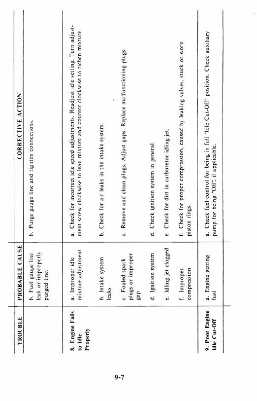
TR
Ol:
BL
E
PRO
BA
BL
E C
Al'S
E
CO
RR
EC
TIV
E A
CT
IO!\
o. Fu
el g
auge
lin
e o.
Purg
e ga
uge
line
and
tight
en c
onne
ctio
ns.
leak
or
impr
oper
ly
purg
ed l
ine.
8.
Engi
ne F
ails
a.
Im
prop
er i
dle
a.
Che
ck f
or i
ncor
rect
idl
e sp
eed
adju
stm
ents
. R
eadj
ust
idle
set
ting.
Tur
n ad
just
-to
Idl
e m
ixtu
re a
djus
tmen
t m
ent
scre
w c
lock
wis
e to
lea
n m
ixtu
re a
nd c
ount
er c
lock
wis
e to
ric
hen
mix
ture
. Pr
oper
ly
b. In
take
sys
tem
b.
Che
ck f
or a
ir l
eaks
in
the
inta
ke s
yste
m.
leak
s ...
r; I .....J
c. Fo
uled
spa
rk
c. R
emov
e an
d cl
ean
plug
s. A
djus
t ga
ps.
Rep
lace
m<.l
Ifun
ctio
ning
plu
gs.
plug
s or
im
prop
er
gap
d. I
gniti
on s
yste
m
d. C
heck
ign
ition
sys
tem
in
gene
ral.
e. Id
ling
jet
clog
ged
e. C
heck
for
dir
t in
car
bure
tor
idlin
g je
t.
f. Im
prop
er
f. C
heck
for
pro
per
com
pres
sion
, ca
used
oy
leak
ing
valv
es.
stuc
k or
wor
n co
mpr
essi
on
pist
on r
ings
.
9, P
oor
Eng
ine
a.
Eng
ine
getti
ng
<.I.
Che
ck f
uel
cont
rol
for
bein
g in
ful
l "I
dle
Cut
-Off
" po
sitio
n. C
heck
aux
iliar
y Id
le C
ut-O
rr
fuel
pu
mp
for
oein
g "O
ff",
if ap
plic
able
.

SECTION X
STORAGE AND REMOVAL FROM STORAGE (ENGINE PRESERVATION FOR ACTIVE
AND STORED AIRCRAFT) TCM has listed three reasonable minimum preservation pro-cedures, that if implemented, will minimize the detriments of rust. and corrosion. The procedures are a general recommendation for our customers. Since local conditions are different and Teledyne Continental Motors has no control over the application, more stringent procedures may be required. Rust and corrosion prevention are the owner's responsibility. It is the owner's responsibility to choose a preservation program that is viable to the particular aircraft's mission.
In all geographical areas the best method of preventing corrosion of the cylinders and other internal parts of the engine, is to fly the aircrft at least once a week, long enough to reach normal operating temperatures which will vaporize moisture and other by-products of combustion. This is even more important in areas of high humidity or when the aircraft is based near the sea coast where instances of corrosion in cylinders has been found after an inactive period of only a few days.
Engines with less than 50 hours total time in service, and engines in aircraft that are flown only occasionally, compared to frequent flying. when exposed to normal atmospheric conditions will tend to exhihit cylinder wall corrosion in a relatively short period of time if t hey are not properly preserved. This would also apply to engines with new or freshly honed cylinders after a top or major overhaul. Preservation must he initiated within five days after delivery and for these first 50 hours, SPECIAL attention should be followed aecording to the engine preservation procedures established under Program I. "Flyahle Storage':
After the accumulation of 50 engine operating hours, a slight varnish deposit on the cylinder walls offers some protection against corrosion. hut also engine preservation procedures as outlined under Program II. "Flyable Storage" should be followed. If you follow these procedures or frequently use your aircraft, it is very unlikely you will have any problems. If problems do arise. verify compliance with the procedures outlined in these programs.
1 0-1

If the aircraft will be stored or statically displayed for an undeter-mined period of time, the engine must be preserved in accordance with the ''Temporary'' or "Indefinite" storage procedures as fits your purpose, listed in this section.
Aircraft engine storage recommendations are broken down into the following categories:
FLYABLE STORAGE (Program I or II) TEMPORARY STORAGE,(up to 90 days) INDEFINITE STORAGE
FLYABLE STORAGE (Program I or II)
Program I - Engines or cylinders with less than 50 operating hours: a. Propeller pull thru every 5 days as per para-
graph 2; and b. Fly every 15 days as per paragraph 3.
Program II - Engines or cylinders with more than 50 operating hours to TBO if not fiown weekly: a. Propeller pull thru every 7 days as per para-
graph 2; and b. Fly every 30 days as per paragraph 3.
I. Service aircraft per normal airframe manufacturer's instruc-tions.
2. The propeller should be rotated by hand without running the engine. For 4 and 6 cylinder straight drive engines, rotate the engine six revolutions, stop the propeller 45° to 90° from the original position. For 6 cylinder geared engines, rotate' the propeller 4 revolutions and stop the propeller 30° to 60° from the original position.
CAUTION ... FOR MAXIMUM SAFETY, ACCOMPLISH ENGINE ROTATION AS FOLLOWS:
10-2
- ------------------ -------~-~------ ---------~-,-------------------
a. Verify magneto switches are "OFF" b. Throttle position "CLOSEI),' l'. Mixture control "IDLE CUT-OFF" d. Set brakes and block aircraft wheels e. I.eave aircraft tic-downs installed and verify that the cabin door latch is open. f. Do not stand within the arc of the propeller blades while turning the propeller.
J. The aircraft should be flow)1 for thirty (30) minutes. reaching. but not exceeding. normal oil and cylinder temperatures. If the aircraft cannot be flown it should be represerved per "Temporary Storage" or "Indefinite Storage". accordingly. Ground running is not an acceptable substitute for flying.
NOTE ... If "b." in each program cannot be accomplished on schedule due to weather. maintenance, etc .. pull the propeller thru daily and accomplish as soon as possible.
It is necess\lry that for future reference. if required. the propeller pull thru and flight time be recorded and verified in the engine maintenance recordi log with the date. time and signature.·
TEMPORARY STORAGE (up to 90 days)
Preparation for Storage
I. Remove the top spark plug and spray preservative oil (Lubri-cation Oil - Contact and Volatile Corrosion - Inhibited. MlL-L-46002. Grade I) at room temperature, through upper spark plug hole of each cylinder with the piston in approximately the bottom dead center position. Rotate crankshaft as each pair of opposite cylinders is sprayed. Stop crankshaft with no piston at top dead center. A pressure pot or pump-up type garden pressure sprayer may be used. The spray head should have ports around the circum-ference to allow complete coverage of the cylinder walls.
10-3
NOTE ... Shown below are some approved preservative oils recommended for use in Teledyne Continental engines for temporary and indefinite storage:
MIL-L-46002. Grade I Oils:
NOX RUST VCI-105
PETROTECT VA
Daubert Chemical Company 4700 S. Central Avenue Chicago. Illinois
Pennsylvania Refining Company Butler. Pennsylvania
2. Re-spray each cylinder \vithout rotating crank. To thoroughly cover all surfaces of the cylinder interior. mo\'e the noule or spray gun from the top to the bottom of the cylinder.
J. Re-install spark plugs.
4. Apply presen'ative to engine interior by spraying the above specified oil (approximately two ounces) through tht: oil filler tube.
5. Seal all engine openings exposed to the atmosphere using sliita ble plugs. or moist ure resista nt ta pc. a nd a ttach red st rea mers at each point.
6. Engines. with propellers installed. that are preser\'cd for storagc in accordance with this scction should havc a tag affixcd to the propeller in a conspicuous placc with the following notation on the tag: "DO NOT TURN PROPELLER - ENGINE PRESERVED". with the preservation date.
NOTE ... If the engine is not returned to flyable status at the expiration of the Temporary (90 day) Storage. it must be preserved in accordance with the Indefinite Storage procedures .
. Preparation for Service
I. Remove seals. tape. paper and streamers from all openings.
10-4

2. With bottom spark plugs removed from the cylinders. hand tllrn propeller several revolutions to clear excess preservative oil. then rc-install spar k plugs:
3. Conduct normal start-up procedure.
4. Give the aircraft a thorough cleaning and visual inspection. A test flight is recommended.
INDEFINITE STORAGE
Preparation for Storage
I. Drain the engine oil and refill with MIL-C-6529 Type II. Start engine and run until normal oil and cylinder head temperatures are reached. The preferred method \vould be to fly the aircraft for thirty (0) minutes. Allow engine to cool to ambient temperature. Accomplish steps I and 2 of "Temporary Storage':
NOTE ... M I L-C -6529 Type" may be formulated by thoroughly mixing one part compound MIL-C-6529 Type I (Esso Rust-Ban 62R. Cosllloline No. 1223 or equivalent) with three parts ne\'.' lubricating oil of the grade recommended for service (all at room temperature). Single grade oil is recommended.
') Apply preservative to engine interior by spraying MIL-L-46002. Grade I oil (approximately two ounces) through the oil filler tube.
3. Install dehydrator plugs MS27215-1 or -2, in each of the top spark plug holes. making sure that each plug is blue in color when installed. Protect and support the spark plug leads with AN-4060 protectors.
4. If the engine is equipped with a pressure type carburetor. preserve this component by the following method. Drain the carburetor by removing the drain and vapor vent plugs from the regulator and fuel control unit. With the mixture control in "Rich" position, inject lubricating oil grade 1010 into the fuel inlet at a pressure not to exceed 10 p.s.i. until oil flows from the vapor vent opening. Allow excess oil to drain, plug the inlet and tighten and
10-5
safety the drain and vapor vent plugs. Wire the throttle in the open position. place bags of desiccant in the intake and seal the opening with moisture resistant paper and tape. or a cover plate.
5. If the carburetor is removed from the engine. place a bag of desiccant in the throat of the carburetor air adapter. Seal the adapter with moisture resistant paper and tape or a cover plate.
6. The TCM fuel injection system docs not require any special preservation preparation. For presenoation of the Bendix RSA-7DA-1 fuel injection system: refer to the Bendix Operation and Service Manual.
7. Place a bag of disiccant in the exhaust pIpes and seal the openings with moisture resistant tape.
8. Seal the cold air inlet to the heater muff with moisture resistant tape to exclude moisture and foreign objects.
9. Seal the engine breather by inserting a dehydrator M S27215-2 plug in the breather hose and clamping in place.
10. Attach a red streamer to each place on the engine where bags of desiccant are placed. Either attach red streamers outside of the se.lled area with tape or to the inside of the sealed area with safety wire to prevent wicking of moisture into the scaled area.
II. Engines. with propellers installed. t hat are preserved for storage in accordance with this section should have each propeller tagged in a conspicuolls place with the following notation on the tag: "DO NOT TURN PROPELLER - ENGINE PRESERVED': with the preservation date.
RETllRNING AN AIRCRAFT TO SERVICE PROCEDURES:
I. Rem()\"e the cylinder dehydrator plugs and all paper. tape. desiccant bags and streamers lIsed to preserve t he engine.
2. Drain the corrosion preventive mixture and re-service with recommended lubricating oil.
10-6

WARNING ... When returning the aircraft to service do not use the corrosion preventive oil referenced in "INDEFINITE STORAGE': paragraph 1 for more than 25 hours.
3. If the carburetor has been preserved with oil. drain it by removing the drain and vapor vent plugs from the regulator and fuel control unit. With the mixture control in "Rich" position, inject service type gasoline into the fuel inlet at a pressure not to exceed 10 p.s.i. until all of the oil is flushed from the carburetor. Re-install the carburetor plugs and attach th~ fuel line.
4. With bottom plugs removed, rotate propeller to clear excess preservative oil from cylinders.
5. Re-install the spark plugs and rotate the propeller by hand through the compression strokes of all the cylinders to check for possible liquid lock. Start the engine in the normal manner.
6. Give the aircraft a thorough cleaning, visual inspection and test flight per airframe manufacturer's instructions.
INSPECTION OF AIRCRAFT STORED PER INDEFINITE STORAGE PROCEDURES:
I. Aircraft prepared for indefinite storage should have the cylinder dehydrator plugs visually inspected every 15 days. The plugs should be changed as soon as their color indicates unsafe conditions of storage. If the dehydrator plugs have changed color in one-half or more of the cylinders, all desiccant material on the engine should be replaced.
2. The cylinder bores of all engines prepared for indefinite storage should be re-sprayed with corrosion preventive mixture every six months, or more frequently if bore inspection indicates corrosion has started earlier than six months. Replace all desiccant and dehydrator plugs. Before spraying, the engine should be inspected for corrosion as follows: Inspect the interior of at least one cylinder on each engine through the spark plug hole. If cylinder shows start of rust, spray cylinder corrosion preventive oil and turn prop over six times, then re-spray all cylinders. Remove at least one rocker box cover from each engine and inspect the valve mechanism.
10-7

---------~=-~~~~---------------------~-~~~~~~-- -~---~~~-~ .. -~--.--.-

SECTION XI
GLOSSARY
ADMP - Absolute dry manifold pressure. It is used in establishing base-line standards of engine performance. Manifold pressure is the absolute pressure in the intake manifold; it is expressed in inches of mercury ("Hg).
AM BI ENT - A term used to denote a condition of the surrounding atmosphere at a particular time. For example: Ambient Tempera-ture or Ambient Pressure.
BliP - Brake Horsepower. The power actually delivered to the engine propeller shaft. It is so called because it was formerly measured by applying a brake to the power shaft of an engine. The required effort to brake the engine could be converted to horse-power - hence: "Brake" horsepower.
BSFC - Brake Specific Fuel Consumption. Fuel consumption stated in pounds per hour per brake horsepower. For example, an engine developing 200 horsepower while burning 100 pounds offuel per hour, has a BSFC of .5
Fuel consumption in PPH
Brake horsepower = 100
200 = .5
COLD SOAKING - Prolonged exposure of an object to cold tem-peratures so that its temperature throughout approaches that of ambient.
CRITICAL ALTITUDE - The maximum altitude at which a component can operate at 100% capacity. For example, an engine with a critical altitude of 16,000 feet cannot produce 100% of its rated manifold pressure above 16.000 feet.
DENSITY ALTITUDE - The effective altitude, based on prevailing temperature and pressure. equivalent to some standard pressure altitude.
DYNAMIC CONDITION - A term referring to properties ofa body in motion.
11-1

E. G .~. -~~-haU:~ G as-T-e-n-,per=~:surcmen' Of~h~S -g~-te-n-1----~'1 perature is sometimes used as an aid to fuel management. II
EXHAUST BACK PRESSURE - Opposition to the flow of exhaust gas, primarily caused by the size and shape of the exhaust system. I
Atmosphere pressure also affects back pressure.
FOUR CYCLE - Short for "Four Stroke Cycle". It refers to the four strokes of the piston in completing a cycle of engine operation (Intake, Compression, Power and Exhaust).
Fl1EL INJECTION - A process of metering fuel into an engine by means other than a carburetor.
GALLERY - A passageway in an engine or component. Especially one through which oil is flowed.
Hg" - Inches of Mercury. A standard for measuring pressure. expecially atmospheric pressure or manifold pressure.
HEAT SOAKED - Prolonged exposure of an object to hot tempera-ture so that its temperature throughout approaches that of ambient.
HllMIDITY - Moisture in the atmosphere. Relative humidity. expressed in percent, is the amount of moisture (water vapor) in the air compared with the maximum amount of moisture the air could contain at a given temperature.
LEAN LIMIT MIXTURE - The leanest mixture permitted for any given power condition. It is not necessarily the leanest mixture at which the engine will run.
MANIFOLD PRESSURE - Absolute pressure as measured in the intake manifold. Usually measured in inches of mercury.
MIXTlIRE - Mixture Ratio. The proportion of fuel to air used for combustion.
NATURALLY ASPIRATED (ENGINE) - A term used to describe an engine which obtains induction air by drawing it directly from the atmosphere into the cylinder. A nonsupercharged engine.
11-2

-----------------------.,
NRP - Normal Rated Power.
O.A.T. - Outside air temperature.
OCTANE NllMBER - A rating which describes relative anti-knock '(detonation) characteristics of fuel. Fuels with greater detonation resistance than 10 octane are given Performance Ratings.
OIL TEMPERATlIRE CONTROL llNIT - A thermostatic unit used to di\"ert oil through or around the oil cooler. as necessary. to maintain oil temperature within'desired limits.
OVERBOOST VALVE - A safcty device used on some turbo-charged engines to relieve excessive manifold pressure in event of a malfunction.
OVEIUIEAD VALVES - An engine configuration 111 which the "ah"es arc located in the cylinder head itself.
OVERSPEED - When an engine has exceeded its rated revolutions per minute.
PERFOI~MANCE RATING - A rating system used to describe the ability of fuel to withstand heat and pressure of combustion as compared with 100 octane fuel. For example. an engine with high compression and high temperature necds a higher Performance Rated fuel than a low compression engine. A rating of 100 130 denotes performancc characteristics of lean (100) and rich (130) mixtures respectively.
PRESSliRE ALTlTllDE - Altitude. usually expressed in feet. (using absolute pressure (static) as a referencc) equivalent to altitude abm"c the standard sea level reference plane (29.92" Hg).
PROPELLER LOAD CVRVE - A plot of horsepower. fuel flow. or manifold pressure verslls RPM through the full power range of one engine lIsing a fixed pitch propeller or a constant spced propellcr running on the low pitch stops. This curve is established or deter-mined during design and development of the engine.
11-3

I>ROPELLER PITCH - The angle between the mean chord of the propeller and the plane or rotation.
RAM - Increased air pressure due to forward speed.
RATED POWER - The maximum horsepower at which an engine is approved for operation. Rated power may be expressed in horsepower or percent.
RETARD BREAKER - A de\.'ice used in magnetos to delay ignition during cranking. It is used to facilitate starting.
RICH LIMIT - The richest fuel/air ratio permitted for any given power condition. It is not necessarily the richest condition at which the engine will run.
ROCKER ARM - A mechanical de\'ice used to transfer motion from the pushrod to the \'al\'e.
SCAVENGE PllMP - A pump (especially an oil pump) to pre\ent accumulation of liquid in some particular area.
SONIC VENTURI - A restriction. especially in cabin pressuri/a-tion systems, to limit the flow of air through a duct.
STANDARD DAY - By general acceptance, temperature 59° I-'j15°C, pressure - 29.92 In. Hg.
STATIC CONDITION - A term referring to properties of a hody at rest.
SllMP - The lowest part of a system. The main oil sump on a wet sump engine contains the oil supply.
TBO - Time Between O\'erhauls. Usually expressed 111 operating hours.
11-4
l I
! I
I

T.D.C. - Top Dead Center. The position in whieh the piston has reached the top of its travel. A line drawn hetween the crankshaft rotational axis. through the connecting rod end axis and the piston pin center would he a straight line. Ignition and valve timing arc stated in terms of degrees hefore or after TOe.
THERMAL EFFICIENCY - Regarding engines. the percent of total heat generated which is cOJl\Trted into useful power.
T.I.T. - Turhine Inlet Temperature. The measurement of E.G.T. at the turhocharger turhine inlet. -
TORQtJE - Twist ing moment or leverage. stated in pounds-foot (or pounds-inch).
VAPOR LOCK - A condition in which the proper flow of a liquid through a system is disturbed by the formation of vapor. Any liquid will turn to vapor if heated sufficient Iy. The amount of heat required for vapori/ation will depend on the pressure exerted on the liquid.
VISCOSITY - The characteristic of a liquid to resist flowing. Regarding oil. high viscosity refers to thicker or "heavier" oil while low viscosity oil is thinner. Relative viscosity is indicated by the specified "weight" of the oil such as 30 "weight" or 50 "weight': Some oils are specified as multiple-viscosity such as IOW30. In sllch cases. this oil is more stable and resists thetendency to thin when heated or thicken when it becomes cold.
VOLATILITY - The tendency of a liquid to vaporize.
11-5

VOU:METRIC EFFICIENCY -The ability of an engine 10 fill its cylinders with air compared to their capacity for air under static conditions. A "normally aspirated" engine will always han~ a yolumetric efficiency of slightly less than 100%. whereas super-chargers permit volumetric efficiencies in excess of 100%.
11-6