Operator s Manual 2017-2018 Model Years - Peterbilt Manitoba
104
Operator’s Manual Operator s Manual ’ 2017-2018 Model Years 2017 Emissions Warranty
Transcript of Operator s Manual 2017-2018 Model Years - Peterbilt Manitoba

Operator’s ManualOperator s Manual’ 2017-2018 Model Years2017 Emissions
Warranty


Engine Operation..................................... 1
Engine Maintenance..................................... 2
Engine Warranty..................................... 3
Contents


© 2017 PACCAR Inc. - All Rights ReservedThis manual illustrates and describes the operation of features or equipment which may be eitherstandard or optional on this vehicle. This manual may also include a description of features andequipment which are no longer available or were not ordered on this vehicle. Please disregard anyillustrations or descriptions relating to features or equipment which are not on this vehicle. PACCARreserves the right to discontinue, change specifications, or change the design of its vehicles at anytime without notice and without incurring any obligation. The information contained in this manual isproprietary to PACCAR. Reproduction, in whole or in part, by any means is strictly prohibited withoutprior written authorization from PACCAR Inc.
Contents

Chapter 1 | ENGINE OPERATIONIn this Chapter:
Safety - Introduction..............................................................................................................................5Emergency - What To Do If.................................................................................................................10Operating Instructions.........................................................................................................................14
ENGINE OPERATION -
4 Y53-1181-1K1 (08/2018)
1

Safety - Introduction
Using this Manual
Please take the time to get acquainted withyour vehicle by reading this Operator’sManual. We recommend that you read andunderstand this manual from beginning toend before you operate this equipment.This manual contains useful information forthe safe and efficient operation of thisequipment. It also provides serviceinformation, with an outline for performingsafety checks and basic preventivemaintenance inspections. We have tried topresent the information you’ll need to learnabout functions, controls, and operation—and to present it as clearly as possible. Wehope you’ll find this manual easy to use.There will be times when you need to takethis manual out of the glovebox. When youdo, please be sure to return it when youare finished using it. That way it will bethere when you need it the next time orwhen you pass the vehicle on to the nextuser.
NOTE
After you’ve read this manual, it shouldbe stored in the cab for convenient ref-erence and remain with this truckwhen sold.
Your vehicle may not have all the featuresor options mentioned in this manual.Therefore, you should pay careful attentionto the instructions that pertain to just yourvehicle. In addition, if your vehicle isequipped with special equipment or optionsnot discussed in this manual, consult yourdealer or the manufacturer of theequipment.There are several tools built into thismanual to help you find what you needquickly and easily. First is the Quick Tableof Contents. Located at the front of themanual, this lists the main subjectscovered and gives section numbers whereyou can find these subjects. Use the QuickTable of Contents to find information on alarge subject like “Maintenance.” Cross-referenced citations also help you get theinformation you need. If some other part ofthe manual contains further information onthe subject you are reading about, we’ll
indicate that in a cross-reference like this:(See Safety Alerts on page 5). You won’thave to go searching for more information.Finally you’ll find a helpful Subject Index.It’s in the back of the manual andalphabetically lists the subjects covered.So if you want information on brakes, forexample, just look under Brake in theSubject Index. You’ll find all the pageslisted where brakes or braking arediscussed.All information contained in this manual isbased on the latest production informationavailable at the time of publication.Kenworth Truck Company Peterbilt MotorsCompany reserves the right to makechanges at any time without notice.
Safety Alerts
Please read and follow all of the safetyalerts contained in this manual. They arethere for your protection and information.These alerts can help you avoid injury toyourself, your passengers and help preventcostly damage to the vehicle. Safety alertsare highlighted by safety alert symbols andsignal words such as “WARNING”,“CAUTION”, or “NOTE”. Please DO NOTignore any of these alerts.
ENGINE OPERATION - Safety - Introduction
Y53-1181-1K1 (08/2018) 5
1

Warnings
The safety message following this symboland signal word provides a warning againstoperating procedures which could causedeath or injury. They could also causeequipment or property damage. The alertwill identify the hazard, how to avoid it andthe probable consequence of not avoidingthe hazard.
WARNING
Hot engine oil can be dangerous. Youcould be burned. Let the engine oilcool down before changing it. Failureto comply may result in death, person-al injury, equipment or property dam-age.
Cautions
The safety message following this symboland signal word provides a caution against
operating procedures which could causeequipment or property damage. The alertwill identify the hazard, how to avoid it, andthe probable consequence of not avoidingthe hazard.
CAUTION
Continuing to operate your vehicle withinsufficient oil pressure will cause seri-ous engine damage. Failure to complymay result in equipment or propertydamage.
Notes
The message following this symbol andsignal word provides important informationthat is not safety related but should befollowed. The alert will highlight things thatmay not be obvious and is useful to yourefficient operation of the vehicle.
NOTE
Pumping the accelerator will not assistin starting the engine.
ForwardHow to use this manual.
This manual contains information for thecorrect operation and maintenance of yourPACCAR engine. Read and follow allsafety instructions. Refer to the WARNINGin the General Safety Instructions on page7. Keep this manual with the equipment.If the equipment is traded or sold, give themanual to the new owner.The information, specifications, andrecommended maintenance guidelines inthis manual are based on information ineffect at the time of printing. PACCARreserves the right to make changes at anytime without obligation. If you finddifferences between your engine and theinformation in this manual, contact yourlocal PACCAR Authorized Repair Locationor write to:
PACCAR c/o PACCAR Engines
ENGINE OPERATION - Safety - Introduction
6 Y53-1181-1K1 (08/2018)
1

PO Box 1518 Bellevue, WA 98009
The latest technology and the highestquality components were used to producethis engine. When replacement parts areneeded, we recommend using onlygenuine parts from PACCAR.
NOTE
Warranty information including theEPA and California Emission Warrantyis located in the section entitled “En-gine Warranty.” Make sure you are fa-miliar with the warranty or warrantiesapplicable to your engine.
IllustrationsSome of the illustrations throughout thismanual are generic and will NOT lookexactly like the engine or parts used inyour application. The illustrations cancontain symbols to indicate an actionrequired and\or an acceptable or NOTacceptable condition.The illustrations are intended to showrepair or replacement procedures. Theprocedure will be the same for all
applications, although the illustration maydiffer.
General Safety InstructionsImportant safety notices about operatingand servicing your engine.
WARNING
Improper practices, carelessness, orignoring any warnings may causedeath, personal injury, equipment orproperty damage.
Before performing any repair, read andunderstand all of the safety precautionsand warnings. The following is a list ofgeneral safety precautions that must befollowed to provide personal safety. Failureto follow these instructions may causedeath or injury. Special safety precautionsare included in the procedures when theyapply.Keep in mind that even a well maintainedvehicle must be operated within the rangeof its mechanical capabilities and the limitsof its load ratings. See the Weight Ratingslabel on the driver's door edge.Every new vehicle is designed to conformto all Federal Motor Vehicle Safety
Standards applicable at the time ofmanufacture. Even with these safetyfeatures, continued safe and reliableoperation depends greatly upon regularvehicle maintenance. Follow themaintenance recommendations found inPreventive Maintenance section. This willhelp preserve your investment.Make sure your vehicle is in top workingcondition before heading out on the road, itis the responsible driver's duty to do so.Inspect the vehicle according to theDriver's Check List.
• Use the proper tool for manuallyrotating the engine. DO NOTattempt to rotate the crankshaft bypulling or prying on the fan. Thispractice can cause death, personalinjury, equipment damage, ordamage to the fan blades, causingpremature fan failure.
• Work areas should be dry, well lit,well ventilated, free from clutter,loose tools, parts, ignition sourcesand hazardous substances.
• Wear protective glasses andprotective shoes when working.
• DO NOT wear loose-fitting or tornclothing. Tie back and/or tuck inlong hair. Remove all jewelry whenworking.
ENGINE OPERATION - Safety - Introduction
Y53-1181-1K1 (08/2018) 7
1

• Before beginning any repair,disconnect the battery (negative [-]cable) and discharge anycapacitors.
• Put a “DO NOT OPERATE” tag inthe operator's compartment or onthe controls.
• Allow the engine to cool beforeslowly loosening the coolant fillercap to relieve the pressure from thecooling system.
WARNING
Removing the fill cap on a hot enginecan cause scalding coolant to sprayout and burn you badly. If the enginehas been in operation within the previ-ous 30 minutes, be very careful in re-moving the fill cap. Protect face,hands, and arms against escaping flu-id and steam by covering the cap witha large, thick rag. DO NOT try to re-move it until the surge tank cools downor if you see any steam or coolant es-caping. In any situation, remove thecap very slowly and carefully. Be readyto back off if any steam or coolant be-gins to escape.
• Always use wheel chocks or properjack stands to support the vehicleor vehicle components beforeperforming any service work. DONOT work on anything that issupported only by lifting jacks or ahoist. Before resting a vehicle onjack stands, be sure the stands arerated for the load you will beplacing on them.
• Before removing or disconnectingany lines, fittings, or related items,relieve all pressure in the air, oil,fuel, and cooling systems. Remainalert for possible pressure whendisconnecting any device from asystem that contains pressure.High pressure oil or fuel can causedeath or personal injury.
• Always wear protective clothingwhen working on any refrigerantlines and make sure that theworkplace is well ventilated.Inhalation of fumes can causedeath or personal injury. To protectthe environment, liquid refrigerantsystems must be properly emptiedand filled using equipment thatprevents the release of refrigerantgas. Federal law requires capturingand recycling refrigerant.
• When moving or lifting any heavyequipment or parts, make sure touse proper techniques andassistance. Ensure all liftingdevices such as chains, hooks, orslings are in good condition andare of the correct load capacity.Make sure all lifting devices arepositioned correctly.
• Corrosion inhibitors and lubricatingoils may contain alkali. DO NOTget the substance in eyes andavoid prolonged or repeatedcontact with skin. DO NOTswallow. If ingested, seekimmediate medical attention. DONOT induce vomiting. In case ofcontact, immediately wash skinwith soap and water. In case ofharmful contact, immediatelycontact a physician. Always keepany chemicals OUT OF REACHOF CHILDREN.
• Naptha and Methyl Ethyl Ketone(MEK) are flammable materials andmust be used with caution. Followthe manufacturer's instructions toensure safety when using thesematerials. Always keep anychemicals OUT OF REACH OFCHILDREN.
ENGINE OPERATION - Safety - Introduction
8 Y53-1181-1K1 (08/2018)
1

• When working on the vehicle, bealert for hot parts on systems thathave just been turned off, exhaustgas flow, and hot fluids in lines,tubes, and compartments. Contactwith any hot surface may causeburns.
• Always use tools that are in goodcondition. Make sure you have theproper understanding of how to usethe tools before performing anyservice work. Use only genuinereplacement parts from PACCAR.
• Always use the same fastener partnumber (or equivalent) whenreplacing items. DO NOT use afastener of lesser quality ifreplacements are necessary. (e.g.,Do not replace a 10.9 grade with8.8 grade fastener.)
• Always torque fasteners and fuelconnections to the requiredspecifications. Overtightening orunder-tightening can allow leakage.
• Close the manual fuel valves priorto performing maintenance andrepairs, and when storing thevehicle inside.
• DO NOT perform any repair whenimpaired, tired, fatigued or after
consuming alcohol or drugs thatcan impair your functioning.
• Some state and federal agencies inthe United States of America havedetermined that used engine oilcan be carcinogenic and can causereproductive toxicity. Avoidinhalation of vapors, ingestion, andprolonged contact with used engineoil.
• DO NOT connect the jump startingor battery charging cables to anyignition or governor control wiring.This can cause electrical damageto the ignition or governor.
• Coolant is toxic. If not reused,dispose of coolant in accordancewith local environmentalregulations.
CAUTION
Corrosive chemicals can damage theengine. DO NOT use corrosive chemi-cals on the engine. Failure to complymay result in equipment, or propertydamage.
California Proposition 65 Warning• Diesel engine exhaust and some of
its constituents are known to theState of California to cause cancer,birth defects, and otherreproductive harm.
• The catalyst substrate located inthe Diesel Particulate Filter (DPF)contains vanadium pentoxide,which has been determined by theState of California to cause cancer.Always wear protective clothingand eye protection when handlingthe catalyst assembly. Dispose ofthe catalyst in accordance withlocal regulations. If catalystmaterial gets into the eyes,immediately flood eyes with waterfor a minimum of 15 minutes. Avoidprolonged contact with skin. Incase of contact, immediately washskin with soap and water. In caseof harmful contact, immediatelycontact a physician.
• Other chemicals in this vehicle arealso known to the State ofCalifornia to cause cancer, birthdefects or other reproductive harm.
• Battery posts, terminals, andrelated accessories contain lead
ENGINE OPERATION - Safety - Introduction
Y53-1181-1K1 (08/2018) 9
1

and lead compounds, chemicalsknown to the State of California tocause cancer and reproductiveharm. Wash hands after handling.
Emergency - What To Do If
Roadside AssistanceWhat to do in an emergency and roadsideassistance information.
Call toll-free to talk to someone at thePACCAR Customer Center:
• Kenworth customers call: 1-800-KW-Assist (1-800-592-7747) |Peterbilt customers call:1-800-4Peterbilt (800-473-8372)
• Open 24-7-365 days a year.• They can help you get roadside
assistance.• They have a custom mapping
system which locates authorizedPACCAR engine dealers andIndependent Service Providers(ISPs) near you and lists types ofservices offered, hours of operationand contact information.
• They can assist with jump and pullstarts, tires, trailers, fines and
permits, chains, towing, hazardousclean-up, out of fuel (roadside),mechanical repairs and preventivemaintenance services.
• They have multilingual agents andaccess to a translation service toensure quality assistance forcustomers in any language.
• They can’t answer your warrantyquestions, but can get you incontact with an authorized dealerwho can.
• The PACCAR Customer Centerservice is FREE.
Stop Engine Lamp
1 2The stop engine warning lamp willilluminate, and an audible tone will sound,when a major engine problem exists. Yourvehicle will be equipped with one of theindicators above, 1 or 2, depending on theengine model.
WARNING
If the Stop Engine warning lamp illumi-nates, it means you have a serious en-gine system problem. This should beconsidered an emergency. You shouldstop the vehicle as safely as possibleand turn OFF the ignition. The vehiclemust be serviced and the problem cor-rected before driving again. Failure tocomply may result in death, personalinjury, equipment or property damage.
For engines with the engine-protectionshutdown feature enabled, the stop enginelamp will begin to flash 30 seconds beforethe engine automatically shuts down. Thewarning lamp alerts the operator to theimpending shutdown.The lamp will also illuminate when the DEFtank is almost empty or the soot level in theDPF is at full capacity. At this levelwarning, regeneration cannot be performedand engine power will be derated.Engine may automatically shut down if thecheck engine lamp and stop engine lampare illuminated and the operator does notcorrect the condition.
ENGINE OPERATION - Emergency - What To Do If
10 Y53-1181-1K1 (08/2018)
1

Engine Oil Pressure Lamp TurnsOnWhat to do if the engine oil pressure lampturns on.
It is important to maintain oil pressurewithin acceptable limits. If oil pressuredrops below the minimum psi a redwarning lamp on the oil pressure gaugeand the Stop Engine Lamp will come ON.
CAUTION
Continuing to operate your vehicle withinsufficient oil pressure will cause seri-
ous engine damage. Failure to complymay result in equipment or propertydamage.
• If the oil pressure fails to rise within10 seconds after the engine starts,stop the engine and determine thecause.
• See Engine Oil Specification for thecorrect oil pressure ranges for yourvehicle's engine.
• If the oil pressure suddenly drops,or the audible alarm and engine oilpressure warning light come onwhile driving, do the following:
1. Slow down carefully.2. Move a safe distance off the road
and stop.3. Place the transmission in neutral
(N) and set the parking brake. (SeeParking Brake Valve and Operatingthe Transmission in your vehicleOperator's Manual, fortransmission shifting and parkingbrake information.)
4. Turn OFF the engine.5. Turn ON the emergency flasher
and use other warning devices toalert other motorists.
6. Wait a 15–20 minutes to allow oil todrain into the engine oil pan, andthen check the oil level. SeeEngine Oil Level.
7. Add oil if necessary. If the problempersists, contact an authorizedPACCAR engine dealer as soon aspossible.
Check Engine Lamp Turns OnWhat to do if the check engine lamp turnson.
Or
Check Engine Lamp - Turns on when aproblem exists, but the vehicle can still besafely driven. Vehicle should be serviced tocorrect the problem but the situation shouldnot be considered an emergency.The lamp will also illuminate when a DPFregeneration or addition of diesel exhaustfluid (DEF) is required. Another function of
ENGINE OPERATION - Emergency - What To Do If
Y53-1181-1K1 (08/2018) 11
1

the check engine lamp is to warn theoperator of an impending idle shutdown.When the idle shutdown timer is 30seconds from expiring, the ECM beginsflashing the check engine warning lamponce per second. When the timer expires,the ECM will turn off the warning lamp andshut down the engine.
Engine is OverheatingThe cooling system may overheat if thecoolant level is below normal or if there issudden loss of coolant. Follow these stepsif the engine is overheating.
CAUTION
The cooling system may overheat ifthe engine coolant is at the minimumlevel. A sudden loss of coolant,caused by a split hose or broken hoseclamp could also lead to an overheatcondition. Always inspect to ensurehoses and clamps are not cracked,worn, or loose. Failure to comply may
result in equipment or property dam-age.
NOTE
The system may also temporarily over-heat during severe operating condi-tions such as:• Climbing a hill on a hot day.• Stopping after high-speed/ high-
load driving.• Debris blocking air flow through
the cooling module (radiator).
If the engine coolant temperature warninglamp comes on and the audible alarmsounds showing an overheat condition, orif you have any other reason to suspect theengine may be overheating, DO NOTTURN OFF THE ENGINE unless a lowwater warning device indicates a loss ofcoolant. Follow these steps:Follow these steps if the engine coolanttemperature is rising, or the temperature isalready above normal, and there are noother warning alarms displayed in theinstrument cluster.
1. Reduce engine speed, or stop.When stopped, place the
transmission in neutral (N) and setthe parking brake. Keep the enginerunning. See the vehicle operator'smanual for instructions ontransmission shifting and parkingbrake information.
WARNING
To reduce the chance of personal in-jury, vehicle damage and/or deathfrom overheated engines, which canresult in a fire, never leave the engineidling without an alert driver present. Ifthe engine should overheat, as indicat-ed by the engine coolant temperaturelight, immediate action is required tocorrect the condition. Continued unat-tended operation of the engine, evenfor a short time, may result in seriousengine damage or a fire. Failure tocomply may result in death, personalinjury, equipment or property damage.
ENGINE OPERATION - Emergency - What To Do If
12 Y53-1181-1K1 (08/2018)
1

WARNING
Removing the fill cap on a hot enginecan cause scalding coolant to sprayout and burn you badly. If the enginehas been in operation within the previ-ous 30 minutes, be very careful in re-moving the fill cap. Protect face,hands, and arms against escaping flu-id and steam by covering the cap witha large, thick rag. DO NOT try to re-move it until the surge tank cools downor if you see any steam or coolant es-caping. In any situation, remove thecap very slowly and carefully. Be readyto back off if any steam or coolant be-gins to escape.
NOTE
Keep the engine running at idle speedunless a warning icon turns on and re-quires an engine to be shut off.
CAUTION
Prolonged periods of idling after theengine has reached operating temper-
atures can decrease engine tempera-ture and could cause engine damagefrom inadequate lubrication. The nor-mal torsional vibrations generated canalso cause transmission wear. An idleshutdown feature, available on PAC-CAR engines, can be programmed toshut the engine down after a period oflow idle operation with no driver activi-ty. A flashing warning lamp will informthe driver of an impending shutdown.Failure to comply may result in equip-ment or property damage.
CAUTION
If the truck is equipped with powertake off (PTO) equipment, the engineshutdown system can be deactivatedwhen the PTO is operational; however,engine idle periods should not exceedfive minutes whenever possible. Fail-ure to comply may result in equipmentor property damage.
2. Check to ensure the Oil PressureGauge reads normal.
3. Make sure the engine fan is turningby switching the Engine Fan Switchfrom AUTO to MAN (Manual).
4. Increase the engine speed to aboutone-half of full operating speed, or1,100 to 1,200 rpm, maximum for 2or 3 minutes.
5. Return the engine speed to normalidle. Monitor the enginetemperature. After the temperaturereturns to normal, allow the engineto idle 3 to 5 minutes beforeshutting it off. This allows theengine to cool gradually anduniformly.
6. If overheating came from severeoperating conditions, thetemperature should have cooled bythis time. If it has not, stop theengine and let it cool beforechecking to see if the coolant islow.
7. Be sure the vehicle is parked onlevel ground or the readings maybe incorrect. Check the coolantlevel at the cooling module surgetank.
Check the coolant level after each tripwhen the engine has cooled. The coolantlevel should be visible within the surge tank—add coolant if necessary.
ENGINE OPERATION - Emergency - What To Do If
Y53-1181-1K1 (08/2018) 13
1

Operating Instructions
Engine Warning LampsExplanation of engine related warninglamps.
The following engine warning lampssection covers only the lamps controlled bythe engine’s Electronic Control Module(ECM). Please refer to the vehicle“Operator's Manual” and “EngineAftertreatement Systems” manuals foradditional warning lamp information.
CAUTION
The installation of electronic devices tothe On Board Diagnostics (OBD) con-nector, the vehicle Controller Area Net-work (CAN), or their associated wiringis not permitted. Doing so can ad-versely affect vehicle performanceand/or cause fault codes to be record-ed. The OBD connector is provided fortemporary connection of service toolsand for diagnostic purposes only.
Stop Engine Lamp
1 2The stop engine warning lamp willilluminate, and an audible tone will sound,when a major engine problem exists. Yourvehicle will be equipped with one of theindicators above, 1 or 2, depending on theengine model.
WARNING
If the Stop Engine warning lamp illumi-nates, it means you have a serious en-gine system problem. This should beconsidered an emergency. You shouldstop the vehicle as safely as possibleand turn OFF the ignition. The vehiclemust be serviced and the problem cor-rected before driving again. Failure tocomply may result in death, personalinjury, equipment or property damage.
For engines with the engine-protectionshutdown feature enabled, the stop enginelamp will begin to flash 30 seconds before
the engine automatically shuts down. Thewarning lamp alerts the operator to theimpending shutdown.The lamp will also illuminate when the DEFtank is almost empty or the soot level in theDPF is at full capacity. At this levelwarning, regeneration cannot be performedand engine power will be derated.Engine may automatically shut down if thecheck engine lamp and stop engine lampare illuminated and the operator does notcorrect the condition.
Engine, Check Engine
Or
Illuminates when a non emissions relatedproblem exists, but the vehicle can still besafely driven. Vehicle should be serviced tocorrect the problem but the situation shouldnot be considered an emergency.
ENGINE OPERATION - Operating Instructions
14 Y53-1181-1K1 (08/2018)
1

Malfunction Indicator Lamp
Illuminates when an engine emissionsfailure has occurred. The vehicle can besafely driven but should be serviced tocorrect the problem. The situation shouldnot be considered an emergency. In somecases, the Malfunction Indicator Lamp(MIL) will activate in conjunction with theHigh Exhaust System Temperature(HEST), Diesel Particulate Filter (DPF) andDiesel Exhaust Fluid (DEF) warning lamps.
NOTE
The malfunction indicator lamp (MIL)will illuminate if the on-board diagnos-tics (OBD) system detects a possibleemissions system failure. The vehicleshould be brought in for service at thenext opportunity to ensure the condi-tion is corrected.
Diesel Particulate Filter (DPF)Warning LampThis warning symbol will appear when theDPF needs to be regenerated and thenalso during the regeneration cycle. Thisicon may also appear if the system isattempting to automatically regeneratewhile the vehicle is in Power Take Offoperation mode.
Engine aftertreatment system includes adiesel particulate filter and DPF warninglamp.
High Exhaust System Temperature(HEST) Warning LampEngine aftertreatment system includes ahigh exhaust system temperature (HEST)warning lamp.
Keep vehicle a safe distance fromcombustible items.
WARNING
Temperature of the tail pipe, exhaustpipe, the diesel particular filter (DPF) /selective catalytic reduction (SCR) de-vice and surrounding components in-cluding enclosures and steps, will beelevated during and shortly after a re-generation event or normal vehicle op-eration when engine is under high orheavy loading.
If the High Exhaust System Temperature(HEST) warning lamp is on:
• Do not park in an area ofcombustible vapors or materials.You must keep combustibles atleast 1.5 m (5 ft) away from theexhaust (outlet) stream (as it exitsthe tail pipe) while the HEST lampis illuminated. Always park yourvehicle outside. Failure to do socould ignite an explosion or harmbystanders which could result inserious injury.
• Do not park in an area wherepeople are close by. You must keep
ENGINE OPERATION - Operating Instructions
Y53-1181-1K1 (08/2018) 15
1

combustibles at least 1.5 m (5 ft)away from the exhaust outlet whilethe HEST lamp is illuminated.Failure to do so could result inserious injury.
• Do not approach the exhaustsystem or surrounding areaswithout allowing adequate time forthe system to cool down. Failure todo so could result in serious burnsto the skin.
Diesel Exhaust Fluid (DEF) LampEngine aftertreatment system includes adiesel exhaust fluid (DEF) warning lamp onthe DEF gauge and additional warninglamps in the instrument cluster.
DEF Warning Lamp in Instrument Cluster
Diesel Exhaust Fluid (DEF) Gauge
211. DEF Symbol2. DEF Gauge Warning Lamp
The DEF lamp(s) will illuminate when thefluid in the DEF tank reaches a low level. Ifthe lamp illuminates but the level is full,seek service immediately for DEF fluidquality or DEF equipment repair.
Engine Braking SystemInformation on using the engine brakingsystem.
An engine compression brake is standardon the MX-13 engines. Optionally, thisengine may be equipped with an exahustbrake. When activated, these devices
create a braking effect on the drive wheels.Because it can help keep your vehicle’sbrakes from overheating, it can save wearand tear on the service brakes. However,the engine compression or exhaust brakeis not an emergency brake or the primaryvehicle brake.
WARNING
Do not operate the engine compres-sion brake when driving/operating yourvehicle bobtail or with a loaded or un-loaded trailer on road surfaces withpoor traction (wet, icy, or snow cov-ered roads) or in heavy traffic. Theremay not be enough weight on the rearaxle to provide traction. Brakingcaused by the normal operation of theengine compression brake couldcause you to lose control of the vehi-cle, resulting in an injury accident.Make sure the engine brake is switch-ed "OFF" when bobtailing or with anunloaded trailer. Failure to comply mayresult in death, personal injury, equip-ment or property damage.
ENGINE OPERATION - Operating Instructions
16 Y53-1181-1K1 (08/2018)
1

WARNING
The service brakes must be used in anemergency. The engine compressionbrake alone might not stop the vehiclefast enough to prevent an accident.The engine compression brake is NOTintended as the primary brake for thevehicle, nor is it an emergency brake.The engine compression brake onlyhelps the service brakes by using en-gine back pressure to slow the drive-train. Use the service brakes for quickstops. You could be seriously injured ifyou relied only on the engine compres-sion brake to stop the vehicle in anemergency. Failure to comply may re-sult in death, personal injury, equip-ment or property damage.
CAUTION
DO NOT operate the engine brake un-til the engine oil temperature is above86°F (30°C). Operation below 86°F(30°C) could cause severe damage tothe engine. Idle the engine four mi-nutes at approximately 1000 rpm to
warm the engine before activating theengine brakes.
NOTE
If your vehicle is equipped with anti-lock brakes (ABS), operation of thecompression brake (if turned ON) maybe interrupted if the ABS system de-tects wheel-slip due to operation onslippery surfaces.
Ideally (on normal road surfaces), youshould slow your vehicle with thecompression brake (where permitted bylaw) and use the service brakes only forstopping completely. Operating this waywill greatly prolong the life of the servicebrakes.
Compression BrakeProper use of engine compression brakes.
With the compression brake switch ON, thebrake automatically creates its brakingeffect when you remove your foot from theaccelerator pedal.The brake switch is located on theaccessory dash panel. It controls whether
the brake is ON (ready to slow the vehicledown) or OFF (no braking action).
1. Do not use the engine compressionbrake to slow the vehicle downwhen you are bobtailing or pullingan empty trailer.
2. Make sure the brake is OFF beforestarting the engine.
3. After the engine is started, warmedup and you are ready to get underway, turn the engine compressionbrake switch ON for added brakingeffect.
NOTE
If your vehicle is equipped with the Ea-ton Vorad® system, operation of thecompression brake may be automati-cally activated.
Compression Brake ControlsUsing the compression brake controls.
There are two switches on the dash panelthat control the engine compression brake.A master switch turns the system ON orOFF. A second switch, located next to themaster switch, controls the braking effect.This switch allows you to choose
ENGINE OPERATION - Operating Instructions
Y53-1181-1K1 (08/2018) 17
1

progressively stronger braking to slow thevehicle down.Engine compression brake controlsinclude:
• ON/OFF switch• Three-position selector switch• Clutch switch• Throttle sensor• Service brake pressure switch• Eaton Vorad® Anti-Lock Braking
SystemEngaging conditions for the enginecompression brake:
• Engine speed must be above 1,000RPM.
• Coolant temperature must beabove 59°F (15°C).
Deactivation conditions for the enginecompression brake:
• Accelerator pedal is depressed.• Clutch pedal is depressed.• Engine speed falls below 800
RPM.• ABS control is active.• ECM recognizes a system
problem.
CAUTION
Operating the engine with a compres-sion brake that will not automaticallydeactivate (i.e. when the dash switchis OFF, clutch pedal is depressed orthrottle is applied) will cause severe in-ternal engine damage. Do not operatethe engine if the compression brakewill not deactivate. Failure to complymay result in equipment or propertydamage.
Engine Compression Brake LevelSwitch OperationHow to operate the compression brake.
There are two switches that control yourvehicle’s engine compression brake. Oneswitch turns the system ON/OFF and thesecond switch controls the braking level.These switches are located on the dashswitch panel.For the three-position engine compressionbrake level switch, there will be 100percent engine braking when the switch isin the up (HIGH) position. In the middle(MEDIUM) position, there will be 66percent engine braking. In the down (LOW)
position there will be 33 percent enginebraking.With the compression brake switch ON, thecompression brake will be engaged whenthe service brake is applied. If the cruisecontrol is operated in conjunction with thecompression brake, the compression brakewill engage to maintain the cruise setspeed.Compression on\off
Compression setting
ENGINE OPERATION - Operating Instructions
18 Y53-1181-1K1 (08/2018)
1

DrivingIntroduction and important informationabout operating your vehicle safely.
Correct care of your engine will result inlonger life, better performance, and moreeconomical operation.Follow the daily maintenance checks listedin Engine Maintenance on page 29.Check the engine oil pressure and enginecoolant gauges, warning lamps, and othergauges daily to make sure they areoperational. Normally each gauge willmake a full sweep when ignition key iscycled ON to indicate that the gauge isoperating correctly.
WARNING
Combustible vapors near the air intakesystem could be ingested into the en-gine, causing the engine to suddenlyaccelerate and overspeed. This condi-tion could result in operator losing con-trol of the vehicle if an unexpected in-crease in engine RPM occurs. Com-bustible vapors could also cause a fire.Do not operate your vehicle in an areawhere combustible chemicals or va-pors may be present. Failure to com-ply may result in death, personal in-jury, equipment or property damage.
NOTE
IT IS THE RESPONSIBILITY OF THEOWNER AND OPERATOR TO OPER-ATE THE VEHICLE IN A SAFE ENVI-RONMENT.
ENGINE OPERATION - Operating Instructions
Y53-1181-1K1 (08/2018) 19
1

NOTE
If the engine is running, do not in-crease engine speed (rpm) or operatethe vehicle until the low oil pressurewarning lamp turns off.
CAUTION
Engaging the starter motor for morethan 30 seconds in any five minute pe-riod may cause it to overheat and candamage the starter.• If starter is engaged continuous-
ly for 30 seconds, you must waitfive minutes before trying to startthe engine to allow the startermotor to cool down.
With the key in the ON position, the enginewarning lamps will come on momentarilyand then go out. The engine warninglamps include:
Or
Check engine lamp; yellow in color.
Stop engine lamp; red in color.
Diesel particulate filter (DPF) statusindicator; yellow in color.
High exhaust system temperature (HEST);amber in color.
Normal Starting ProcedureSteps for starting the engine in normaltemperatures.
Follow this engine starting procedure whenthe outside temperature is above 50° F(10° C).
1. Ensure the parking brake is set ONand the transmission shift lever isin neutral. For automatictransmissions, be sure the shiftlever is in the neutral position (N).For automatic transmissions thathave park (P) position, place theshift lever in park.
2. With the accelerator pedal in theidle position, turn the ignition key tothe START position to start theengine.
3. If the engine does not start after 10seconds, release the key. Wait anadditional 10 seconds to allow thestarter motor to cool, then trystaring the engine again.
4. Once the engine has started, waitfor the oil pressure to rise, and thelow oil pressure warning lamp toturn off, before increasing RPM.
If the engine does not start, or runserratically, see Starting After the Fuel Tank
ENGINE OPERATION - Operating Instructions
20 Y53-1181-1K1 (08/2018)
1

Has Run Dry or After Fuel System Servicehas been Performed on page 61
Cold Weather StartingSteps for starting the engine in coldtemperatures.
Follow this engine starting procedure whenthe outside temperature is below 50° F(10° C).
CAUTION
To reduce the possibility of damage tothe lubricating oil pan, due to the ma-terials used in the manufacture of thelubricating oil pan, under no circum-stances should an external heatsource be applied directly or indirectlyto the lubricating oil pan.
1. Follow the Normal StartingProcedure on page 20.
Refer to the vehicle operator's manualinstructions for any additional cold weatherstarting procedures.
2. If starting a cold engine, slowlyincrease the engine speed. Thisprovides adequate lubrication tothe bearings and gives ample time
to allow the oil pressure tostabilize.
CAUTION
The use of starting aids, such as ether,may result in damage to the engineand aftertreatment system.
If an engine must idle for an extendedperiod of time, it should be done at a fastidle (1,000 RPM maximum) at coolanttemperatures below 150°F (70°C).
3. For coolant temperatures below150°F (70°C), use a low gear anddrive at moderate engine speeduntil the engine coolant hasreached operating temperature. Donot let the engine idle longer thannecessary.
CAUTION
Do not operate the engine at low idlefor long periods of time when the cool-ant temperature is below the normaloperating range. This could result inthe following:
• Fuel dilution of the lubricatingoil.
• Carbon buildup in the com-bustion chamber.
• Sticking of the valves in thecylinder head.
• Reduced performance.• Damage to aftertreatment
components.
Starting Procedure After ExtendedShutdown or Oil ChangeGuideline on starting the engine afterprolonged shutdown or oil change.
After extended shutdown or an oil changefollow the Normal Starting Procedure onpage 20.
Operating the EngineAfter the engine starts:
Monitor the oil pressure and coolanttemperature gauges frequently. Refer to Engine Oil Specifications on page 40 and Engine Coolant Specifications on page 45for recommended operating pressures andtemperatures. Shut off the engine if anypressure or temperature does NOT meetthe specifications.
ENGINE OPERATION - Operating Instructions
Y53-1181-1K1 (08/2018) 21
1

Engine Operating RangeInformation on operating the engine atproper RPM.
CAUTION
Operating the engine at full throttle be-low peak torque will shorten engine lifeto overhaul, can cause serious enginedamage, and is considered engineabuse. DO NOT operate the engine atfull throttle operation below peak tor-que rpm for more than 30 seconds.Failure to comply may result in equip-ment or property damage.
PACCAR engines are designed to operateat full throttle under momentary conditionsdown to peak torque engine speed. This isconsistent with recommended operatingpractices.
CAUTION
Operating the engine beyond the max-imum engine speed can cause severeengine damage. Use proper operatingtechniques for the vehicle to preventengine overspeed. See Engine Speci-
fications for maximum engine speed.Failure to comply may result in equip-ment or property damage.
NOTE
For applications with high idle-time, tohelp reduce soot loading in the after-treatment system, avoid long periodsof idling. If idling is required, increaseidle-speed using the cruise controlfunction.
Engine ShutdownBefore stopping the engine follow theseprecautions.
NOTE
DO NOT shut off the engine immedi-ately. A hot engine stores a greatamount of heat and it does not cooldown immediately after it is shut off.Always cool the engine down beforeshutting it off. You will greatly increaseits service life.
Idle the engine at 1,000 RPM for fourminutes. Then low idle for 30 secondsbefore shutdown. This will allow circulatingcoolant and lubricating oil to carry heataway from the cylinder head, valves,pistons, cylinder liners, turbocharger, andbearings. This way you can prevent enginedamage that may result from unevencooling.
Electromagnetic InterferenceInformation on electromagneticinterference (EMI).
If not installed correctly, some vehicleaccessories (CB radios, mobiletransmitters, etc.) can generate and useradio frequency energy that may causeelectromagnetic interference (EMI)between the accessory and theelectronically controlled fuel system. Underthese conditions, PACCAR is not liable forany performance problems with either thefuel system or the accessory. EMI is notconsidered by PACCAR to be an enginefailure and therefore is not warrantable.
System EMI SusceptibilityPACCAR products are designed andtested for minimum sensitivity to incomingelectromagnetic energy. The fuel system
ENGINE OPERATION - Operating Instructions
22 Y53-1181-1K1 (08/2018)
1

EMI susceptibility has been designed witha high tolerance against EMI and in mostnormal circumstances, if not all,electromagnetic energy-emitting devicesthat meet the Federal CommunicationsCommission legal requirements shouldcause no interference.
System EMI Radiation LevelsElectronic components are required topass various PACCAR and industry EMIspecifications. Our testing has shown thatwhen the engine is properly installed andmaintained, it will not interfere with properlyinstalled onboard communicationequipment.If any interference condition is noticed,follow these suggestions to reduce theamount of EMI:
1. Locate the accessory receivingantenna further away.
2. Check with the accessory supplierrepresentative in your area to:
• Accurately calibrate theaccessory for proper frequency,power output, and sensitivity.
• Determine the optimumantenna location by obtainingantenna reflective energy datameasurements.
• Ensure that the optimumantenna type and mountingarrangement is being used.
• Ensure the accessoryequipment is properlyconstructed for maximumfiltering to reject incomingelectromagnetic noise.
Operating on Level and DryPavementTips for driving on level and dry roads.
WARNING
Do not use the engine brake when op-erating on road surfaces with poortraction (such as wet, icy, or snow cov-ered roads or gravel). Retarders cancause the wheels to skid on a slipperysurface. You could lose control of thevehicle and/or jackknife if the wheelsbegin to skid, resulting in an accident.Failure to comply may result in death,personal injury, equipment or propertydamage.
WARNING
Do not operate the engine compres-sion brake when driving/operating yourvehicle bobtail or with a loaded or un-loaded trailer on road surfaces withpoor traction (wet, icy, or snow cov-ered roads) or in heavy traffic. Theremay not be enough weight on the rearaxle to provide traction. Brakingcaused by the normal operation of theengine compression brake couldcause you to lose control of the vehi-cle, resulting in an injury accident.Make sure the engine brake is switch-ed "OFF" when bobtailing or with anunloaded trailer. Failure to comply mayresult in death, personal injury, equip-ment or property damage.
Remove Foot from Accelerator
MPH0
10
2030 40 50
60
7080
ENGINE OPERATION - Operating Instructions
Y53-1181-1K1 (08/2018) 23
1

To reduce vehicle speed, put the enginebrake ON/OFF switch in the "ON" position.Remove your foot from the acceleratorpedal and clutch pedal. The engine brakeswill immediately begin to operate, slowingthe vehicle.For operation on dry and relatively flatsurfaces, when greater retarding power isnot required, put the two-position selectorswitch in the "LOW" position.For operation on dry pavement whenmaximum retarding power is required, putthe three-position selector switch in the"HI" position.
Operating on Grades and DryPavementTips for driving on grades and dry roads.
WARNING
The engine brake is not intended asthe primary brake for the vehicle, noris it an emergency brake. The servicebrakes must be used in an emergency.Relying solely on the engine brake tostop the vehicle in an emergencycould cause an accident and lead topersonal injury. The engine brake onlyhelps the service brakes by using
pressure to slow the drive train. Youmust use the service brakes for quickor emergency stops. Failure to complymay result in death, personal injury,equipment or property damage.
"Control speed" is the speed at which theforces pushing a vehicle down a grade areequal to the forces holding it back.Do Not Exceed Governed Engine Speed
OKOKRPM
2100 2300
1
2
33
4
5
R
RPM
1
2
3
44
5
RMPH
0
10
2030 40 50
60
7080
MPH0
10
2030 40 50
60
7080
WARNING
Do not use the engine brake when op-erating on road surfaces with poortraction (such as wet, icy, or snow cov-ered roads or gravel). Retarders cancause the wheels to skid on a slippery
surface. You could lose control of thevehicle and/or jackknife if the wheelsbegin to skid, resulting in an accident.Failure to comply may result in death,personal injury, equipment or propertydamage.
CAUTION
The engine ECM maintains a record ofmaximum rpm. Exceeding the maxi-mum rpm will be considered driverabuse and will affect the engine war-ranty. See Engine Spcifications.
ENGINE OPERATION - Operating Instructions
24 Y53-1181-1K1 (08/2018)
1

WARNING
DO NOT use an exhaust brake whendriving bobtail or with an unloadedtrailer. There may not be enoughweight on the rear axle to provide trac-tion. This could cause a loss of controland jackknife resulting in an injury ac-cident. Make sure the exhaust brake isswitched “OFF” when bobtailing orwith an unloaded trailer. Failure tocomply may result in death, personalinjury, equipment or property damage.
CAUTION
Never exceed governed engine speedbecause engine damage can occur.Operating engine beyond the gov-erned speed causes additional strainon valve train and internal engine com-ponents. Operate the engine withingoverned engine speed.
NOTE
Once you have determined what thesafe speed is for your vehicle, operatethe engine brakes with the transmis-sion in the lowest gear that will notcause the engine speed to exceed therated engine speed. The optimumbraking power of the engine brakes isreached at rated engine speed. Cor-rect gear selection, therefore, is criti-cal.
The selector switch can be used to varybraking power as road conditions change.Vehicle service brakes must be used whenadditional braking power is required.Slow Down Around Curves
25MPH
The engine brake is NOT intended as theprimary brake for the vehicle, nor is it anemergency brake. The engine brake onlyhelps the service brakes by using pressureto slow the drivetrain. Use the servicebrakes for quick stops.Braking Truck on Grade
ENGINE OPERATION - Operating Instructions
Y53-1181-1K1 (08/2018) 25
1

WARNING
Do not drive with frequent or continu-ous use of the service brakes. Thiscan overheat the brakes and result inexcessive lining wear, increased stop-ping distances, possibly an accidentand may lead to personal injury. Be-fore descending a steep grade, shift toa lower gear, keep the vehicle speedlow, and avoid continuous applicationto the brakes. Failure to comply mayresult in death, personal injury, equip-ment or property damage.
NOTE
The longer or steeper the hill, the moreimportant it is to use your enginebrakes. Make maximum use of yourengine brakes by gearing down andletting the engine brakes do the work.
Shift to a Lower Gear on Grade
RPM
1
2
3
4 R
55
OK
2100
RPM
1
2
3
44
5
RMPH
0
10
2030 40 50
60
7080
OK
MPH0
10
2030 40 50
60
7080
2100
If frequent use of the vehicle servicebrakes is required, it is recommended thata slower control speed be used byselecting a lower transmission gear.
Tips for Operation on Slick Roads
WARNING
To reduce the possibility of personalinjury or property damage, always al-low for extra distance between yourvehicle and other objects when usingthe service brakes or engine brakes onslick roads.
The operation of any vehicle is difficult topredict on slick roads. The first 10 to 15minutes of rainfall are the most dangerous,as road dirt and oil mixed with rain create avery slippery surface.
WARNING
Do not use any of the vehicle’s retard-ers in any situation that requires an im-mediate stop and/or in situations ofpoor traction (such as wet, icy or snowcovered roads). Trying to use the re-tarder instead of the service brakesmay cause a loss of vehicle control,which may result in an accident involv-ing death or personal injury.
When driving on slick roads, start with the“ON/OFF” switch in the “OFF” position andthe two-position selector switch in the“LOW” position. If your tractor is equippedwith a twin-screw rear axle, position thepower divider switch in the “unlocked”position. Remove your foot from theaccelerator pedal to make sure the vehiclewill maintain traction with the retardingpower of the engine alone. If the vehicledrive wheels begin to skid or if there is afishtailing motion, DO NOT activate theengine brakes. If traction is maintained
ENGINE OPERATION - Operating Instructions
26 Y53-1181-1K1 (08/2018)
1

using the retarding power of the enginealone and more braking power is required,switch the two-position selector switch tothe “LOW” position and activate the enginebrakes by switching the “ON/OFF” switchto the “ON” position. If the vehicle’s drivewheels begin to skid or there is a fishtailingmotion, switch the “ON/OFF” switch to the“OFF” position. If traction is maintainedwhen the engine brakes are activated andmore braking power is required, move thetwo-position selector switch to the “HI”position. Again, if the vehicle has losttraction or if there is a fishtailing motion,switch the “ON/OFF” switch to the “OFF”position. DO NOT attempt to use theengine brakes in the “HI” position.
ENGINE OPERATION - Operating Instructions
Y53-1181-1K1 (08/2018) 27
1

Chapter 2 | ENGINE MAINTENANCEIn this Chapter:
Maintenance Requirements................................................................................................................ 29Maintenance Schedule........................................................................................................................31Engine Specifications..........................................................................................................................37Engine Lubricating Oil Recommendations and Specifications............................................................39Engine Oil Specifications.................................................................................................................... 40Engine Lubrication and Filter Intervals................................................................................................40Cooling System Maintenance............................................................................................................. 42Engine Coolant Specifications............................................................................................................ 45Extended Life Coolant.........................................................................................................................45Fuel Recommendations...................................................................................................................... 46Warranty and the Use of Biodiesel Fuel..............................................................................................48Recommendations to Avoid Fuel Gelling............................................................................................ 48Maintenance Procedures.................................................................................................................... 49Engine Identification............................................................................................................................79
ENGINE MAINTENANCE -
28 Y53-1181-1K1 (08/2018)
2

MaintenanceRequirements
Engine MaintenanceIntroduction and important maintenancerequirements.
PACCAR recommends that the engine bemaintained according to the maintenanceschedule in this section.If the engine is operating in ambienttemperatures below 0°F (-18°C) or above100°F (38°C), perform maintenance atshorter intervals. Shorter maintenanceintervals are also required if the engine isoperated in a dusty environment or iffrequent stops are made.Some of these maintenance proceduresrequire special tools or must be completedby qualified personnel. Contact your localPACCAR authorized repair location fordetailed information.If your engine is equipped with acomponent or accessory not manufacturedby PACCAR Inc, refer to the componentmanufacturer's maintenancerecommendations.
WARNING
Never idle your vehicle for prolongedperiods of time if you sense that ex-haust fumes are entering the cab. In-vestigate the cause of the fumes andcorrect it as soon as possible. If thevehicle must be driven under theseconditions, drive only with the windowsopen. Failure to repair the source ofthe exhaust fumes may result in death,personal injury, equipment or propertydamage.
WARNING
Exhaust fumes from the engine con-tain carbon monoxide, a colorless andodorless gas. Do not breathe the en-gine exhaust gas. A poorly maintained,damaged or corroded exhaust systemcan allow carbon monoxide to enterthe cab. Entry of carbon monoxide intothe cab is also possible from other ve-hicles nearby. Failure to properly main-tain your vehicle could cause carbonmonoxide to enter the cab, resulting indeath or personal injury.
Cleaning the EngineEngine cleaning precautions.
When cleaning the engine, follow theinstructions from the vehicle manufactureroperator's manual and observe allenvironmental protection regulations.
CAUTION
Do not direct water onto electricalcomponents, plug connectors, seals orflexible hoses on the engine. Watermay enter the part causing electricaldamage or contaminating the engineoil. To prevent damage to engine com-ponents, keep the water moving at alltimes while cleaning the engine. Fail-ure to comply may result in equipmentdamage.
Daily or Refueling MaintenanceChecksEngine Fuel Filter / Water SeparatorDaily and refueling maintenance check forthe engine fuel filter/water separator.
Automatic water drain, no maintenancerequired.
ENGINE MAINTENANCE - Maintenance Requirements
Y53-1181-1K1 (08/2018) 29
2

Chassis Fuel Filter / WaterSeparatorDaily and refueling maintenance check forthe chassis fuel filter/water separator.
This procedure should be followed as partof daily and refueling maintenance checks.
1. Drain trapped water (if equipped).
Air Intake PipingDaily and refueling maintenance check forengine air intake piping.
This procedure should be followed as partof daily and refueling maintenance checks.
1. Inspect hose/pipe condition –deterioration/signs of leaking.
2. Inspect hose clamps for tightnessand pinching/cutting of hoses.
3. Inspect clearance to othercomponents.
4. Check air restriction gauge.
Aftertreatment Exhaust PipingDaily and refueling maintenance check foraftertreatment exhaust piping.
This procedure should be followed as partof daily and refueling maintenance checks.
1. Inspect for cracks.
2. Inspect for clearance to othercomponents (i.e. electricalharnesses, etc.).
3. Inspect hose/pipe condition –deterioration/signs of leaking.
Cooling FanDaily and refueling maintenance check forengine cooling fan.
This procedure should be followed as partof daily and refueling maintenance checks.
1. Inspect for cracks.2. Inspect for clearance to other
components.
Coolant LevelDaily and refueling maintenance check forengine coolant level.
Replacement or top up coolant shouldhave the same antifreeze concentrationand corrosion inhibitor content as theoriginal coolant in the cooling system. Ifoperating in sub-freezing conditions, a60/40 mix of antifreeze and distilled watermay be substituted.Always dilute antifreeze to the correctconcentration based on freeze protectionbefore adding it to the cooling system.Adding or using 100% antifreeze in acooling system may result in cooling
system plugging and overheatingproblems.This procedure should be followed as partof daily and refueling maintenance checks.Perform the following steps to check thecoolant level:
1. Check that vehicle is a on a levelsurface.
2. Ensure engine has not been run forseveral hours.
CAUTION
Due to thermal expansion the coolantlevel CANNOT be checked if the cool-ant is above ambient temperature orthe engine has not completely cooled.The coolant level indicated on awarmed system will be inaccurate andcan lead to low coolant conditions dur-ing cold-starts.
3. Check coolant level. It should bevisible through the clear plasticsurge tank.
4. Add coolant as necessary untilproper level is reached.
See Radiator Fill Procedure on page 65for coolant level indentifieres for differentsurge tanks.
ENGINE MAINTENANCE - Maintenance Requirements
30 Y53-1181-1K1 (08/2018)
2

NOTE
The pressure cap (on the side of thesurge tank) should NEVER be re-moved. The fill cap (On the top, notthe side of the surge tank) is the cor-rect fill point.
Diesel Exhaust FluidDaily and refueling maintenance check ofdiesel exhaust fluid (DEF).
This procedure should be followed as partof daily and refueling maintenance checks.
1. Check level of diesel exhaust fluid.
NOTE
It is recommended to top up DEFwhen refueling. See Engine Aftertreat-ment Systems Operator’s Manual forDEF information.
Visual Inspection of EngineDaily and refueling visual check of engine.
This procedure should be followed as partof daily and refueling maintenance checks.
1. Check for any signs of fluid leaks.2. Ensure all access caps/covers are
installed and tight.
Bi-weekly Maintenance CheckEngine Oil Level CheckRoutine maintenance check for engine oillevel.
This procedure should be followed as partof routine maintenance checks.
1. See Engine Oil Level on page 49
Maintenance Schedule
Maintenance Schedule IntervalsMaintenance schedule intervals for normaland severe duty applications.
Engine Maintenance Intervals - Normal Duty/Line Haul
Maintenance Interval Miles Kilometers Hours Months
Less than 20 % Idle Time
ENGINE MAINTENANCE - Maintenance Schedule
Y53-1181-1K1 (08/2018) 31
2

Maintenance Interval Miles Kilometers Hours Months
A 37,000 60,000 1,125 6
B 75,000 120,000 2,250 12 (1 year)
C 150,000 240,000 4,500 24 (2 years)
D 225,000 360,000 6,750 36 (3 years)
E300,000 480,000 6,750 36 (3 years)
F
G 450,000 725,000 13,500 48 (4 years)
H 600,000 965,000 18,000 72 (6 years)
J 750,000 1,200,000 24,000 96 (8 years)
Greater than 20% Idle Time
A 25,000 40,000 750 6
B 50,000 80,000 1,500 12 (1 year)
C150,000 240,000 4,500 24 (2 years)
D
E300,000 480,000 6,750 36 (3 years)
F
G 450,000 725,000 13,500 48 (4 years)
ENGINE MAINTENANCE - Maintenance Schedule
32 Y53-1181-1K1 (08/2018)
2

Maintenance Interval Miles Kilometers Hours Months
H 600,000 965,000 18,000 72 (6 years)
J 750,000 1,200,000 24,000 96 (8 years)
Engine Maintenance Intervals - Severe Duty/Vocational
Maintenance Interval Miles Kilometers Hours Months
A 15,000 24,000 400 6
B 30,000 48,000 800 12 (1 year)
C 60,000 96,000 1,600 24 (2 years)
D (Pick-up & Delivery/Refuse) 90,000 144,000 1,600 12 (1 year)
D (Severe Duty/Vocational) 120,000 192,000 3,200 24 (2 years)
E 150,000 240,000 4,500 24 (2 years)
F 300,000 480,000 9,000 36 (3 years)
G 450,000 725,000 13,500 48 (4 years)
H As indicated by the system to the operator. Interval H is greater than or equal to interval E.
J 750,000 1,200,000 24,000 96 (8 years)
ENGINE MAINTENANCE - Maintenance Schedule
Y53-1181-1K1 (08/2018) 33
2

Maintenance Interval Miles Kilometers Hours Months
Vocational vehicle applications include: Agriculture, Concrete Mixers, Construction, Crane, Dumps, Emergency/Fire, HeavyEquipment, Loggers, Mining, Oil Field, Refuse, Pick-up & Delivery, Snowplows, and Wrecker.
Preventative Maintenance ScheduleList of recommended maintenance tasksand intervals that should be performed.
Perform maintenance at whichever intervaloccurs first. At Maintenance ScheduleIntervals, perform all previous maintenancechecks that are due for scheduledmaintenance.
NOTE
This maintenance schedule is for anormal duty cycle engine operation.Severe duty/vocational applicationswill need to adjust mileage, kilometer,hour, or time interval based on the En-gine Lubrication and Filter Intervals.
NOTE
Due to the design of the crankcaseventilation module, routine service ofthis component is not required.
ENGINE MAINTENANCE - Maintenance Schedule
34 Y53-1181-1K1 (08/2018)
2

Engine Maintenance Schedule
Component 2 Maintenance TaskRecommended Preventative
Maintenance Interval
A B C D E F G H J
Aftertreatment System Diesel Particulate Filter (DPF) Dry Cleaningon page 71 - Dry Cleaning Strategy •
Diesel Particulate Filter (DPF) WetCleaning on page 72 - WetCleaning Strategy
•
Diesel Exhaust Fluid (DEF) Filter on page72 •
Air System & Compressor Air Compressor on page 74 •
Air Cleaner on page 74 •
Charge Air System Charge Air Piping on page 74 •
Charge Air Cooler on page 74 •
Charging / Cranking System Electrical Harness / Cables on page 77 •
Batteries, Cables, and Connections onpage 77 •
ENGINE MAINTENANCE - Maintenance Schedule
Y53-1181-1K1 (08/2018) 35
2

Component 2 Maintenance TaskRecommended Preventative
Maintenance Interval
A B C D E F G H J
Cooling System Coolant/Antifreeze Condition on page 63 •
Radiator Hoses on page 64 •
Replace Coolant Filter on page 64 •
Change Extended Life Coolant on page45 •
Crankshaft Crankshaft - Vibration Damper on page77 •
Drive Belts Engine Belt Checks on page 68 •
Fan Belt Tensioner on page 68 •
Poly V-belt and Fan Drive Belt Removal onpage 69 - Replace •
Engine Lubrication – Line Haul Engine Lubrication and Filter Intervals onpage 40
•
Engine Lubrication – Severe Duty •
Crankcase Ventilation Replace filter and o-ring gaskets if the CCVis serviceable. See Crankcase Ventilation(CCV) Module Maintenance on page 55to determine if your engine has aserviceable CCV
•
ENGINE MAINTENANCE - Maintenance Schedule
36 Y53-1181-1K1 (08/2018)
2

Component 2 Maintenance TaskRecommended Preventative
Maintenance Interval
A B C D E F G H J
Fuel System Fuel Filter on page 59 - Replace 1 •
Mounting Bolts Engine Mounting Bolts on page 77 •
Valves See Engine Valves on page 78 for recommended maintenance intervals.
Engine SpecificationsEngine specifications includinghorsepower, firing order, displacement,weight, and other engine characteristics.
PACCAR MX-13 Engine Specifications
Horsepower See EPA Label on top of the valve cover or on the mixer manifold.
Firing Order 1, 5, 3, 6, 2, 4
Crankshaft Rotation (viewed from front of engine) Clockwise
1 Use of poor quality fuel may require more frequent fuel filter element service.2 Follow the manufacturers' recommended maintenance procedures for the starter, alternator, batteries, electrical components,
exhaust brake, charge-air cooler, radiator, air compressor, air cleaner, refrigerant compressor, and fan clutch.
ENGINE MAINTENANCE - Engine Specifications
Y53-1181-1K1 (08/2018) 37
2

Displacement 787 CID (12.9 liters)
Bore and Stroke 5.12 in. (130 mm) × 6.38 in. (162 mm)
Dry Weight (excludes Flywheel and Air Compressor) 2,600 lb. (1,179 kg.)
Idle Speed Approximately 650 rpm
High Idle speed (low hp/high hp) 2,100/2,200 rpm
Maximum continuous engine speed with engine brake active 2,100 rpm
Fault code registers with engine brake active 2,300 rpm
Maximum Continuous No Load Governed Speed 2,200 rpm
Engine Over Speed 2,301 to 2,499 rpm
Misuse 2,300 rpm or greater
REPTO Rotation and Ratio Clockwise, 1.2:1
REPTO Torque Limit 613 Ft-lb
FEPTO Torque Limit 515 Ft-lb
Filter SpecificationsUse of non-genuine filters.
PACCAR is not responsible for problemscaused by non-genuine filters that do notmeet PACCAR performance or durabilityrequirements.
Contact your local PACCAR authorizedrepair location for specific part numbers.
CAUTION
Use of non-genuine oil filters cancause severe engine damage.
ENGINE MAINTENANCE - Engine Specifications
38 Y53-1181-1K1 (08/2018)
2

Engine Lubricating OilRecommendations andSpecificationsPACCAR engine oil type, viscosity, andadditives.
A major factor in maintaining engineperformance and durability is the properuse of quality engine lubricating oils usedin conjunction with the appropriate oil drainand filter change intervals. Attempting toextend the oil and filter change intervalbeyond the manufacturersrecommendations may decrease enginelife due to factors such as corrosion,deposits, and wear.See Engine Lubrication and Filter Intervalsto determine which oil drain interval to usefor an application.
NOTE
It is the operator’s responsibility to fol-low these recommendations to ensurethat the engine warranty is not affect-ed.
PACCAR recommends the use of high-quality SAE 10W-30 API CK-4/CJ-4 heavy-duty engine oil.The primary PACCAR recommendation isfor the use of 10W-30 multigradelubricating oil for normal operation atambient temperatures above 5°F (-15°C).For ambient temperatures below 5°F(-15°C) SAE 5W-30 may be used, providedit meets API CK-4/CJ-4 oil specificationsand biodiesel or biodiesel blended fuel isnot used as fuel for the engine. Using amultigrade oil helps improve enginecranking in low-temperature conditions,reduces deposit formation, increasesengine durability and increases fueleconomy.Engine Oil Viscosity Chart
-40 -20 0 20 40 60 80 100 120 140
-40 -30 -20 -10 0 10 20 30 40 50 60
Temperature °F
Temperature °C
5W405W40
10W4010W40
15W4015W40
10W30 (2)5W305W30
(1)
1. If engine is equipped with an activeoil pan heater, use before enginestart.
2. Initial factory oil fill: API CK-410W-30
NOTE
Any of the oil weights listed in thechart above are acceptable to use aslong as the oil meets API CK-4/CJ-4oil specifications.
New Engine Break-In OilsPACCAR does not approve the use ofspecial “break-in” engine lubricating oils fornew or rebuilt PACCAR engines. It isrecommended to use the same lubricatingoil for engine break-in that will be usedduring normal operation.
Aftermarket Oil Additive UsagePACCAR does not recommend the use ofaftermarket oil additives. Today's high-quality engine lubricating oils are verysophisticated. Most oils already containprecise amounts of additives blended intothe lubricating oil to meet stringentperformance requirements.
ENGINE MAINTENANCE - Engine Lubricating Oil Recommendations and Specifications
Y53-1181-1K1 (08/2018) 39
2

These oils meet performancecharacteristics that conform to the lubricantindustry standards and are sufficientprotection when used according to therecommendations. Aftermarket lubricating
oil additives are not necessary to enhanceengine oil performance and may in somecases reduce the oil's capability to protectthe engine.
Engine Oil SpecificationsEngine oil system specifications.
Engine Oil Specifications for PACCAR MX-13 - Low and High Horsepower Ratings
Oil Pressure at Low Idle (min allowable) 650 ± 50 rpm 14.5 psi at 239°F (100 kPa at 115°C) oil temperature
At Road Speed 900-1200 rpm (min allowable) 20-29 psi at 239°F (140-200 kPa at 115°C) oil temperature
At Road Speed 1200-2100 rpm (min allowable) 29 psi at 239°F (200 kPa at 115°C) oil temperature
Regulated Oil Pressure (nominal) 33 psi at 239°F (230 kPa at 115°C) oil temperature
Total System Capacity (oil pan and new oil filters) 42 U.S. qts (40.0 liters)
Engine Lubrication andFilter IntervalsOil change intervals for normal and severeduty applications.
Oil drain interval recommendations arebased on vehicle application or engine dutycycle. PACCAR recommends the use ofhigh quality lubricating oil as indicated in
the Engine Lubricating OilRecommendations and Specificationssection.Perform these maintenance proceduresaccording to the Preventive MaintenanceSchedule.
CAUTION
Extending the oil and filter change in-terval beyond the recommendationswill decrease the engine life due tofactors such as corrosion, deposits,
and wear. Engine oil filters capture dirtand remove deposits from the oil toprolong the life of internal moving com-ponents. Follow the oil and filterchange intervals as recommended inthis section of the manual. Failure tocomply may result in equipment orproperty damage.
ENGINE MAINTENANCE - Engine Oil Specifications
40 Y53-1181-1K1 (08/2018)
2

Determining Type of Vehicle Application for Engine Oil Drain Intervals
Severe Duty - Vocational * Normal Duty - Line Haul
Fuel Consumption Less than 6 MPG (2.6 km/L) 6 MPG (2.6 km/L) or greater
Gross Vehicle Weight Greater than 80,000 lb. (36,300 kg) 80,000 lb. (36,300 kg) or less
* Vocational vehicle applications include: Agriculture, Concrete Mixers, Construction, Crane, Dumps, Emergency/Fire, HeavyEquipment, Loggers, Mining, Oil Field, Refuse, Pick-up & Delivery, Snowplows, and Wrecker.
ENGINE MAINTENANCE - Engine Lubrication and Filter Intervals
Y53-1181-1K1 (08/2018) 41
2

Engine Oil and Filter Change Intervals
Vehicle Application Change Interval
Oil Drain and Filter Replacement Interval
Normal Duty (Line Haul) - less than 20%idle time
75,000 miles (120,000 km)
2,250 hours or 12 months
Normal Duty (Line Haul) - more than 20%idle time 50,000 miles (80,000 km)
1,500 hours or 12 months
Severe Duty (Vocational*) 30,000 miles (48,000 km)
800 hours, or 12 months
* Vocational vehicle applications include: Agriculture, Concrete Mixers, Construction, Crane, Dumps, Emergency/Fire, HeavyEquipment, Loggers, Mining, Oil Field, Refuse, Pick-up & Delivery, Snowplows, and Wrecker.
NOTE
If B6-B20 biodiesel fuel is used, the oiland filter must be changed every40,000 mi (64,000 km) for line haul ap-plications; every 20,000 mi (32,000
km) for severe duty, or every sixmonths. Cooling System
MaintenanceInformation about concentration andcondition of coolant, including filter.
ENGINE MAINTENANCE - Cooling System Maintenance
42 Y53-1181-1K1 (08/2018)
2

The cooling system in your vehicle wasfactory filled with extended life coolant thatmeets or exceeds all ASTM D6210 andCaterpillar EC-1 requirements. PACCARrecommends only using a 50/50 mixture ofdistilled water and ELC when coolingsystem service is required. A 50/50 mixtureof ELC and distilled water will providefreeze protection down to –34°F (–36.7°C),which is adequate for most locations inNorth America. For extremely coldoperating conditions, a 60/40 mixture(coolant/water ratio) can be used toprovide freeze protection down to -62°F(-52.2°C).Unless otherwise optioned, factory fillcoolant is an ethylene glycol, nitritedorganic acid technology (NOAT) extendedlife coolant (ELC) formulation at a 50:50coolant-to-distilled water mixture. Thefactory fill exceeds ASTM D6210 andCaterpillar EC-1 requirements. Maintainingcoolant chemistry and freeze protection iscritical to engine and cooling systemcomponent health and longevity.
WARNING
Coolant is toxic. DO NOT get the fluidin eyes. If contact occurs, flood eyes
with large amounts of water for 15 mi-nutes. Avoid prolonged or repeatedcontact with skin. In case of contact,immediately wash skin with soap andwater. DO NOT take internally. If swal-lowed, seek immediate medical atten-tion. DO NOT induce vomiting. Failureto comply may result in death, person-al injury, equipment or property dam-age.
CAUTION
The engine cooling system has veryspecific maintenance and inspectionrequirements. Failure to follow require-ments can damage the engine. Enginedamage can include but is not limitedto freezing, boiling, corrosion, pittedcylinder liners. This information isfound in the engine manufacturersowner’s manual. It is the owner’s re-sponsibility to follow all requirementslisted in the engine manufacturersowner’s manual.
NOTE
Coolant is harmful to the environment.Unused coolant must be stored as atoxic hazardous material in leakproofcontainers. Used coolant must beprocessed as industrial chemicalwaste. Please follow HAZMAT guide-lines with both used and unused cool-ants.
CAUTION
Use of non-genuine coolant filters cancause severe engine damage.
ConcentrationCheck the level of freeze/boiloverprotection, which is determined by theglycol concentration. Use a glycolrefractometer to determine glycol level.Add coolant to obtain the coolant/waterratio required to provide the protection youneed. A 50/50 mix of coolant and water isadequate for most applications. Forextremely cold operating conditions, theratio can be adjusted to a higherconcentration of coolant.
ENGINE MAINTENANCE - Cooling System Maintenance
Y53-1181-1K1 (08/2018) 43
2
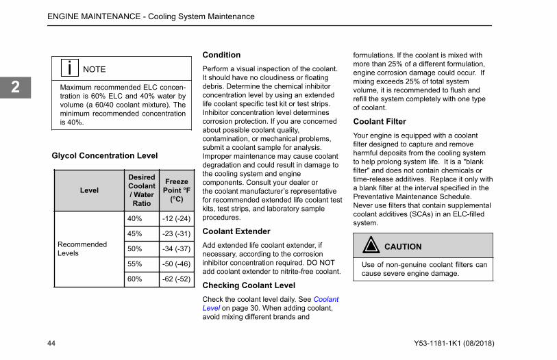
NOTE
Maximum recommended ELC concen-tration is 60% ELC and 40% water byvolume (a 60/40 coolant mixture). Theminimum recommended concentrationis 40%.
Glycol Concentration Level
Level
DesiredCoolant/ WaterRatio
FreezePoint °F
(°C)
RecommendedLevels
40% -12 (-24)
45% -23 (-31)
50% -34 (-37)
55% -50 (-46)
60% -62 (-52)
ConditionPerform a visual inspection of the coolant.It should have no cloudiness or floatingdebris. Determine the chemical inhibitorconcentration level by using an extendedlife coolant specific test kit or test strips.Inhibitor concentration level determinescorrosion protection. If you are concernedabout possible coolant quality,contamination, or mechanical problems,submit a coolant sample for analysis.Improper maintenance may cause coolantdegradation and could result in damage tothe cooling system and enginecomponents. Consult your dealer orthe coolant manufacturer’s representativefor recommended extended life coolant testkits, test strips, and laboratory sampleprocedures.
Coolant ExtenderAdd extended life coolant extender, ifnecessary, according to the corrosioninhibitor concentration required. DO NOTadd coolant extender to nitrite-free coolant.
Checking Coolant LevelCheck the coolant level daily. See CoolantLevel on page 30. When adding coolant,avoid mixing different brands and
formulations. If the coolant is mixed withmore than 25% of a different formulation,engine corrosion damage could occur. Ifmixing exceeds 25% of total systemvolume, it is recommended to flush andrefill the system completely with one typeof coolant.
Coolant FilterYour engine is equipped with a coolantfilter designed to capture and removeharmful deposits from the cooling systemto help prolong system life. It is a "blankfilter" and does not contain chemicals ortime-release additives. Replace it only witha blank filter at the interval specified in thePreventative Maintenance Schedule.Never use filters that contain supplementalcoolant additives (SCAs) in an ELC-filledsystem.
CAUTION
Use of non-genuine coolant filters cancause severe engine damage.
ENGINE MAINTENANCE - Cooling System Maintenance
44 Y53-1181-1K1 (08/2018)
2

Cooling System Sealing Additivesand Soluble Oils
OK
1
1. Do not use soluble oils or sealingadditives.
CAUTION
The use of sealing additives or solubleoils in the cooling system can causedamage to the engine. These additivescan plug various areas of the radiator,EGR system and oil cooler. The plug-ging of the cooling system can hamperheat transfer, causing internal enginedamage. Do not use sealing additivesor soluble oils in the cooling system.The use of sealing additives can:
• Build up in coolant low-flowareas.
• Plug the radiator and oil cooler.• Damage the water pump seal.• Damage heat transfer surfaces.• Damage seals and hoses.• Corrode brass and copper.Failure to comply may result in equip-ment or property damage.
Engine CoolantSpecificationsEngine capacity, pressure, andtemperature specifications.
Engine Coolant Specifications forPACCAR MX-13
Coolant Capacity Approx. 13 gallons3
(49 liters)
MinimumRecommendedPressure Cap
15 psi (103 kPa)
Maximum EngineCoolant OutletTemperature
223°F (106°C)
NOTE
Coolant volumes are dependent onchassis model and cab/ sleeper heateroptions.
Extended Life CoolantInformation on using Extended Life Coolant(ELC).
Perform these maintenance proceduresaccording to the Preventative MaintenanceSchedule.
• Conduct coolant maintenancechecks including freeze point, pH,nitrite and carboxylate tests at least
ENGINE MAINTENANCE - Engine Coolant Specifications
3 Varies with vehicle equipment
Y53-1181-1K1 (08/2018) 45
2

twice annually to maintain engineprotection.
Nitrited Extended Life CoolantFor nitrited formulations (NOAT), a heavy-duty extended life coolant that meetsASTM D6210 and Caterpillar EC-1specifications must be used.The change interval for extended-lifecoolant containing nitrite and molybdate is750,000 miles (1,200,000 km) or 12,000hours of on-road use (8 years or 15,000hours of off-highway use) on initial fill withno extender added. The change interval is1,000,000 miles (1,600,000 km)/20,000hours/8 years with an extender addition at500,000 miles (800,000 km)/10,000hours/4 years.
Nitrite-Free Extended Life CoolantNitrite-free organic acid technology coolant(OAT) may be used if it meets DAF 74002.The change interval for nitrite free coolantis 600,000 miles (1,000,000 km) or 6years, with no extender needed. DO NOTadd coolant extender to nitrite-free coolant.Follow the coolant supplier's drain/flush/fill/diluting percentages when servicing avehicle filled with nitrite-free coolant.Additional Recommendations:
• Antifreeze is essential for freeze,overheat, and corrosion protection.The use of supplemental coolantadditives (SCAs) is notrecommended for extended-lifecoolants.
Recommended Extended LifeCoolant SuppliersAuthorized PACCAR Engine dealer
®
Fuel RecommendationsPrecautions and recomendations forselecting and using the right diesel fuel.
WARNING
The use of diesel fuel that has beenmixed with other fuels may cause anexplosion. DO NOT mix gasoline, alco-hol, or gasohol with diesel fuel. Makesure you know your fuel source anduse the recommended diesel fuel asindicated in this section of the manual.Failure to comply may result in death,
personal injury, equipment or propertydamage.
CAUTION
Dirt or water in the fuel system cancause severe damage to both the fuelpump and the fuel injectors. Due to theprecise tolerances of diesel injectionsystems, it is extremely important thatthe fuel be kept clean and free of dirtor water. Know your fuel source andmake sure all steps are taken for dis-pensing or using clean fuel in your ve-hicle. Failure to comply may result inequipment or property damage.
ENGINE MAINTENANCE - Fuel Recommendations
46 Y53-1181-1K1 (08/2018)
2

CAUTION
Unapproved fuel can reduce economyor possibly damage fuel system com-ponents. Unapproved fuels typically donot have enough lubricity elements inthe fuel to properly lubricate the fuelinjection system. Be sure you followthe fuel recommendations as indicatedin this section of the manual. Failure tocomply may result in equipment orproperty damage.
CAUTION
Using diesel fuels blended with lubri-cants may cause damage to your ex-haust aftertreatment system. Serviceintervals for aftertreatment systemswill be reduced. DO NOT use dieselfuel blended with lubricating oil in en-gines equipped with an aftertreatmentsystem. Failure to comply may resultin equipment or property damage.
CAUTION
DO NOT use high-sulfur diesel fuel asit will damage the exhaust aftertreat-ment system. Also, the engine will notmeet emission regulations. Use onlyultra-low-sulfur diesel (ULSD) fuel.Failure to comply may result in equip-ment or property damage.
CAUTION
If ultra-low-sulfur diesel (ULSD) fuel isnot used, the engine may not meetemission regulations, and damagemay occur to the exhaust aftertreat-ment system. The use of high-sulfurdiesel fuel will damage the exhaust af-tertreatment system and impact theengine emission. ULSD fuel is re-quired for correct operation of the af-tertreatment. The engine has been op-timized for use with an aftertreatmentsystem together with ULSD fuel tomeet the 2013 U.S. EnvironmentalProtection Agency regulations. Failure
to comply may result in equipment orproperty damage.
NOTE
PACCAR recommends that the cetanenumber of diesel fuel be a minimum of45 for engines that are expected to op-erate at temperatures below 32ºF(0ºC) and a minimum of 42 for enginesthat are operated at temperaturesabove 32ºF (0ºC).
Using diesel fuel with a lower-than-recommended cetane number can causehard starting instability, and excessivewhite smoke. To maintain satisfactoryoperation at low ambient temperatures, it isimportant to specify diesel fuel of thecorrect cetane number.PACCAR requires all permissible fuels tohave adequate fuel lubricity. Lubricity canbe determined by ASTM, specificationD6079, ISO 12156, High FrequencyReciprocating Rig (HFRR) in which the fuelmust have a wear scar diameter of 0.02 in.(0.5 mm) or less.The use of Ultra-low-sulfer-diesel (ULSD)fuel is required for this engine in order to
ENGINE MAINTENANCE - Fuel Recommendations
Y53-1181-1K1 (08/2018) 47
2

meet emission regulations and to preventdamage to the engine and exhaust system.The use of other grades of diesel fuelsother than ULSD fuel will be considered ause of incorrect fuel for the engine.PACCAR is not responsible for failurescaused by the use of incorrect fuel, oil orDEF or by water, dirt or other containmentsin the fuel or DEF.
Warranty and the Use ofBiodiesel FuelBiodiesel information and warrantyprecautions.
PACCAR Inc. approves the use ofbiodiesel fuel blends from 6 to 20 percentby volume in diesel fuel providing that thefollowing conditions are met:
• The biodiesel used in the blendmeets ASTM Standard D6751 orEN 14214 specifications.
• The biodiesel used in the blend issourced from a BQ-9000Accredited Producer.
• The finished blend meets the fuelproperties of the ASTM StandardD975 (up to B5 blend) or D7467(B6 to B20 blend).
• The engine oil and oil filter arechanged per the modifiedschedule. See the EnginePreventative MaintenanceSchedule.
• The fuel filter is changed every25,000 miles/40,000 km.
The use of approved biodiesel fuel doesnot affect the PACCAR engine warranty.Failures caused by the use of non-approved biodiesel fuels or other fueladditives that are of unacceptable qualityor do not meet specified industry standardsare not considered as defects of parts orworkmanship by PACCAR and thereforewill not be covered by the PACCAR enginewarranty.PACCAR recommends that customersintending to use biodiesel blends becomefamiliar with the additional handlingconsiderations of these fuels such asageing, metal compatibility and tendency toabsorb water. Please reference the fuelsupplier’s technical information or industryguidelines such as the American TruckingAssociation Truck Maintenance Councildocument RP 357.In particular, operators should be awarethat biodiesel blends are more prone tocold flow (gelling) and filter plugging issuescompared to conventional diesel fuel. If
vehicles are expected to be operated intemperatures below freezing, care shouldbe taken to ensure that both the biodieselfuel used and the appropriate vehicle fuelsystem accessory heaters are utilized.Operators should also be aware thatbiodiesel energy content (by volume) islower than diesel which can reduce fueleconomy by up to two percent.
Recommendations toAvoid Fuel GellingInformation to prevent fuel gelling.
• Use appropriate fuel grade/blendfor conditions.
• Specify vehicle with proper coldweather equipment (12v electricpre-heater, fuel blending valve, fuelcoolant heater, 12v line heatersand tank heaters).
PACCAR does not recommend the use offuel additives, however, should a customerdecide there is a need for temporary use ofa winter fuel additive, PACCAR offers thefollowing guidance:
• Use an industry known, high qualityproduct (EPA approved).
ENGINE MAINTENANCE - Warranty and the Use of Biodiesel Fuel
48 Y53-1181-1K1 (08/2018)
2

• Only use the additive for theminimum time needed.
• Follow additive manufacturer'sinstructions exactly.
• Refuel with proper grade fuel assoon as possible.
Maintenance Procedures
Engine Oil LevelHow to check engine oil level
To check engine oil level, park vehicle onlevel ground and wait 15 minutes aftershutting off engine. After the engine is shutoff it will take at least 15 minutes for all theengine oil to return to the sump.
NOTE
It takes approximately 15 minutes forall the oil to run into the sump whenthe engine is ‘warm.’ If the level ischecked immediately after switchingoff the engine, the dipstick will show alow oil level.
Make sure that the vehicle suspension issitting flat, both lengthwise and crosswise.
Check this carefully on a vehicle with airsuspension.Engine coolant should be at or above theoperating temperature of 180°F (82°C).This procedure should be followed as partof routine maintenance checks.
1. Twist the dipstick handle to unlockit, then pull the dipstick out of theholder.
2. Wipe the dipstick clean with a lint-free cloth.
3. Reinsert the dipstick into theholder.
4. Remove the dipstick from theholder and check the oil level. The
oil level should always be betweenthe two marks on the dipstick.
5. Reinstall the dipstick and twist tolock it in place.
ENGINE MAINTENANCE - Maintenance Procedures
Y53-1181-1K1 (08/2018) 49
2

Oil Level Indication on DipstickHigh and low marks on the dipstick indicatelevel of oil in the oil pan.
NOTE
On the engine oil dipstick, the differ-ence between the low oil level mark(2) and high oil level mark (1) is 6.3US quarts (6 liters).
Engine Oil Dip Stick Markings
1
2
1. High oil level (1)2. Low oil level (2)
Topping Up the Engine OilSteps for topping up the engine oil.
If checking the engine oil just after stoppingthe engine, wait 15 minutes for the oil todrain back into the oil pan before checkingthe fluid level.This procedure should be followed when oillevel is low and more oil needs to beadded.
1. Top up with oil, if necessary, via thefiller opening. Use the correctgrade in the correct quantity.
2. After topping up, wait one minuteand check the oil level again.
3. Reinstall the oil fill cap and twist tolock it in place.
NOTE
See Lubricating Oil Recommendationsand Specifications..
Engine Oil Fill Location
ENGINE MAINTENANCE - Maintenance Procedures
50 Y53-1181-1K1 (08/2018)
2

Oil Drain Plug for Composite PanWhat to do after draining oil.
After draining the oil, replace the drain plugif:
Oil Pan Drain Plug Installation
1
1. Stop• The plug is leaking.• The O-ring is missing.
• The plug/O-ring assembly isdamaged.
• The retention detent cannot be feltduring installation.
Torque the drain plug to its stop.Oil Drain Plug Detent
1
1. Detent
NOTE
This engine is equipped with a compo-site oil pan and drain plug. Careshould be taken to avoid over-torquingthe drain plug.
ENGINE MAINTENANCE - Maintenance Procedures
Y53-1181-1K1 (08/2018) 51
2

Engine Oil FilterProcedure for replacing engine oil filters.
Oil Filter Module
12
3
1. Full-Flow Oil Filter2. Centrifugal Bypass Oil Filter3. Oil Filter Cap Lock
Your engine is equipped with a full-flow oilfilter and centrifugal bypass oil filter. Bothfilters are designed to capturecontaminants and remove deposits fromthe oil to prolong the life of internal movingcomponents.Always use quality engine lubricating oils inconjunction with the appropriate oil drainand filter change intervals. Refer to the“Preventative Maintenance Schedule” for
the recommended oil and filter changeservice interval.
CAUTION
Use of non-genuine oil filters cancause severe engine damage.
Oil Filter Removal PreparationPreparing for replacing engine oil filters.
This procedure should be followed beforereplacing engine oil filters.
CAUTION
Before beginning to remove and/ordisconnect any components, wait atleast 5 minutes after the key switch isturned OFF for the aftertreatment DEFdosing system to purge the DEF fromthe system. The DEF system purgesto prevent damage from freezing. Fail-ure to comply may result in equipmentor property damage.
WARNING
Turn off the engine and place the igni-tion switch in the OFF position beforedisconnecting the battery clamps. DONOT place any tools or other materialson top of or close to the batteries. Thiscan cause a dangerous high currentshort circuit and, in the worst case, abattery explosion. Keep all objectsaway from the battery terminals. Al-ways break the contact between thebattery clamp and the negative termi-nal before working on the vehicle.Working on a vehicle while the batteryis connected may result in electrical in-jury or damage. Always disconnect thebattery at the negative terminal whenperforming service procedures. Failureto comply may result in death, person-al injury or equipment damage.
ENGINE MAINTENANCE - Maintenance Procedures
52 Y53-1181-1K1 (08/2018)
2

WARNING
Electrical shock hazard: Never discon-nect the battery clamp when the en-gine is running. Disconnecting the bat-tery clamps while the engine is runningmay result in death, personal injury orequipment damage from electrical arc-ing or damage to electrical compo-nents.
1. Disconnect the chassis batterycable at the negative batteryterminal.
2. Place an oil collection pan directlyunder the oil filter.
Centrifugal Bypass Oil FilterRemovalProcedure to remove the centrifugalbypass oil filter on PACCAR MX-13engines.
Follow the procedure below after readingOil Filter Removal Preparation.
Oil Filter Module
1. Clean the oil filter cap andsurrounding area to ensure dirtdoes not fall into the oil filtermodule.
CAUTION
Dirt in the engine oil lubrication systemcan lead to significant damage to theengine. Failure to comply may result inequipment or property damage.
2. Remove the cap of the centrifugaloil filter. Use a hexagonal socket ora box wrench to avoid damagingthe oil filter cap.
3. Remove the centrifugal filter.
4. Remove the O-ring from the screwcap.
WARNING
Lubricating oil can cause skin irritationor skin injury. To prevent skin injury,avoid unnecessary contact with the lu-bricating oil. Wear protective clothing,eye wear and gloves when handlinglubricating oil. Failure to comply mayresult in personal injury.
ENGINE MAINTENANCE - Maintenance Procedures
Y53-1181-1K1 (08/2018) 53
2

Centrifugal Bypass Oil FilterInstallationProcedure to intall the centrifugal bypassoil filter on PACCAR MX-13 engines.
Follow the steps below to install thecentrifugal bypass oil filter:Centrifugal Bypass Oil Filter Installation
12
3
1. Lightly lubricate the new O-ring (1)with engine oil.
2. Fit the new O-ring (1) onto the cap(2).
3. Mount the centrifugal filter (3) withits top side in the bearing of thescrew cap (2).
4. Check to ensure the centrifugalfilter (3) can rotate freely.
5. Position the screw cap carefullyonto the oil module.
6. Tighten the screw cap by hand untilit reaches the end position.
7. Tighten the screw cap to 30 lb-ft(40 N·m). Use a hexagonal socket,or box wrench, to avoid damagingthe oil filter cap.
Full-flow Oil Filter RemovalProcedure for removing full-flow oil filter onPACCAR MX-13 engines.
Full-flow Oil Filter Module
1. Unscrew the cap a few turns anddrain the filter housing. Use ahexagonal socket, or box wrench,to avoid damaging the oil filter cap.
2. Remove the cap, with the oil filtercartridge, from the filter housing.
Then remove the oil filter cartridgefrom the screw cap.
3. Remove the O-ring from the screwcap.
WARNING
Lubricating oil can cause skin irritationor skin injury. To prevent skin injury,avoid unnecessary contact with the lu-bricating oil. Wear protective clothing,eye wear and gloves when handlinglubricating oil. Failure to comply mayresult in personal injury.
Full-flow Oil Filter InstallationProcedure for installing full-flow oil filter onPACCAR MX-13 engines.
Use the following procedure to install full-flow oil filters.
1. Lightly oil the new O-ring.2. Install the new O-ring onto the
screw cap.3. Install the screw cap, with the oil
filter cartridge, onto the filterhousing. Tighten the screw cap to30 lb-ft (40 N·m). Use a hexagonalsocket to avoid damaging the oilfilter cap.
ENGINE MAINTENANCE - Maintenance Procedures
54 Y53-1181-1K1 (08/2018)
2

After Replacing Engine Oil Filter(s)Procedure for what to do after installingnew oil filters.
Follow the steps below after installing newoil filters:
1. Reconnect the chassis batterycable at the negative batteryterminal. See "Oil Filter RemovalPreparation."
2. Add approved engine oil to themaximum level marked on thedipstick. If the engine is running adifferent weight of oil, be sure totop-off the engine oil with the samebrand and viscosity of oil.
3. Start and run the engine for 5 to 10minutes and check for any oilleaks.
4. Remove oil collection pan anddispose of any spillage properly.
5. Shut down the engine and checkengine oil level and top up asnecessary. See "Engine Oil Level."
Crankcase Ventilation (CCV)Module MaintenanceServicing the CCV module.
This engine may be equipped with aservicable Crankcase Ventiflation Module(CCV). This emissions related componentseparates oil from air coming from thecrank case vent. The unit sends theextracted oil back into the engine andprovides clean vent air back into the airintake.See the images below of the serviceableCCV. If the CCV on your engine does notmatch these images then your CCV is notservicable. If your CCV appears like theseimages, then remove and replace the filterand O-ring gaskets at the prescribedmaintenance interval.Serviceable CCV
Non Serviceable CCV
How to Remove a CrankcaseVentilation ModuleMaintenance instructions for servicableCrankcase Ventilation (CCV) modules.
Follow the steps below to remove the CCV.1. Disconnect the chassis battery
cable at the negative batteryterminal.
2. Place an oil collection pan directlyunder the CCV module.
ENGINE MAINTENANCE - Maintenance Procedures
Y53-1181-1K1 (08/2018) 55
2

3. Clean the CCV module andsurrounding area to avoid dirtcontaminating the module.
NOTE
Keep the new CCV module in its pack-aging until it's time to install it to theengine.
4. Disconnect the electrical connectorand outlet hose.
Serviceable CCV - MX-13, Front
5. Remove the CCV module byunscrewing the six bolts using aratchet with 13 mm socket.
NOTE
Be careful when removing the CCV toprevent an oil spill. Oil may be presentin the CCV-to-engine interface.
6. Wipe the on-engine sealinginterface with a clean, lint-free rag
(not shown). Remove old facegasket.
CCV - MX-13 Mounting
1
How to Disassemble a CCVDisassembly instructions for servicableCrankcase Ventilation (CCV) modules.
Ensure that you have followed these steps How to Remove a Crankcase VentilationModule on page 55 before proceeding withdisassembling the unit.Follow the steps below to disassemble theCCV to access to the replaceable filter andgaskets.
1. Lay the CCV module on a cleantable with the engine interfacefacing down.
ENGINE MAINTENANCE - Maintenance Procedures
56 Y53-1181-1K1 (08/2018)
2

2. Unscrew the four bolts (1) using aratchet with 10 mm socket.
CCV Filter/Motor Installation
1
3 2
1. Housing2. Motor3. Mounting Flange
3. Remove the motor from thehousing and take out the filter.
Do not remove the retaining ring e-clipfrom the shaft. The e-clip (1) being slantedis OK (2).CCV Retainer Ring Installation
1 2
4. Remove the gasket from the motoras well as the gasket from thehousing, and wipe the two gasketgrooves with a clean, lint-free rag.
5. Properly dispose of the filter andgaskets.
How to Reassemble a CCV UnitReassembly instructions for servicableCrankcase Ventilation (CCV) modules
Follow the steps below to reassemble theCCV after the old filter and gaskets havebeen removed.
ENGINE MAINTENANCE - Maintenance Procedures
Y53-1181-1K1 (08/2018) 57
2

CCV Motor/Filter Assembly
Fit onto Shaft Turn to Slide Ensure Shaft Protrudes
1
1. Install the new O-ring gasket on themotor and the new face gasket onthe CCV-to-engine interface of theCCV housing. Lubricate the twogaskets with clean engine oil.
2. Orient the motor so that the shaft isfacing upward.
3. Take the new filter assembly out ofits packaging, fit it on the shaft andturn it so that it slides into the notchand shaft protrudes through theend of the filter.
4. Install the motor with the new filterin the housing in horizontal
position. When reinstalling motor,ensure shaft and bottom bearingare aligned (1).
CAUTION
DO NOT force motor into the CCVhousing, or damage to the bottombearing may occur.
5. Tighten and torque the four bolts(1) using a torque wrench to 70.8+/- 8.4 lb-in. (8.0 +/- 1.0 N·m).
CCV Filter/Motor Installation
1
3 2
1. Housing2. Motor3. Mounting Flange
ENGINE MAINTENANCE - Maintenance Procedures
58 Y53-1181-1K1 (08/2018)
2

How to Install a CCV Unit to theEngineInstallation instructions for servicableCrankcase Ventilation (CCV) modules.
Follow the steps below to install the CCV.1. Install the CCV module on the
engine. Tighten and torque the sixbolts using a torque wrench to 16.2+/- 1.5 lb-ft (22.0 +/- 2.0 N·m).
2. Attach electrical connector andinlet/outlet hoses.
Fuel FilterImportant information on replacing enginemounted cartridge type fuel filters.
Perform these maintenance proceduresaccording to the Preventative MaintenanceSchedule.
WARNING
When removing the fuel filter, a quanti-ty of fuel will escape. Do not smoke orallow an open flame in close proximity.Failure to do so could ignite a fire orcause an explosion which could resultin serious injury to you and/or bystand-ers. Failure to comply may result in
death, personal injury, equipment orproperty damage.
NOTE
The fuel filter and the hand pump arelocated on the left-hand side of the en-gine, as viewed from the driver's seat.
NOTE
Use of poor quality fuel may requiremore frequent fuel filter element serv-ice.
DescriptionThe fuel filter/water separator moduleprovides fine-particle filtration, waterseparation, water-in fuel-sensing,automatic water draining, lifetimepurification of drained water with acharcoal filter, 12V preheating and systemmanual priming in a singular easy toservice module.
NOTE
The engine and fuel module should beoperated in cold climates with accepta-ble cold climate fuel blends which no-ticeably reduces wax gelling in the fuelfilter cartridge. The fuel module in-cludes a 12V preheater to support pre-heat of the fuel for initial start-up inmild climates. Failure to operate withacceptable cold climate fuel may resultin insufficient fuel flow to the fuel injec-tion system.
Biodiesel
NOTE
If B6-B20 biodiesel fuel is used, thefuel filter must be changed every25,000 mi (40,000 km).
ENGINE MAINTENANCE - Maintenance Procedures
Y53-1181-1K1 (08/2018) 59
2

Fuel Filter RemovalProcedure for removing the PACCARMX-13 fuel filter.
Follow the steps below to remove the fuelfilter:Fuel Module
1
2
3
4
1. Fuel Filter Cap2. Fuel Filter3. Manual Priming Pump
4. Fuel Filter Housing1. Clean the fuel filter cap and
surrounding area to ensure dirtdoes not fall into the fuel module.
CAUTION
Dirt in the fuel system can lead to sig-nificant damage to the fuel system.Failure to comply may result in equip-ment or property damage.
2. Loosen the fuel tank cap to relieveany pressure in the fuel tank.
3. Remove the fuel filter cap byrotating it counter-clockwise with awrench, automatic draining of fuelwill be initiated, wait 5 minutes forcomplete fuel draining to preventfuel from leaking or dripping on thestarter motor.
NOTE
The fuel filter cartridge is a disposablefilter and must not be cleaned andreused. Dispose of the filter as chemi-cal waste.
4. Remove the fuel filter cartridge.
Fuel Filter Installation - PACCARMX-13Procedure for installing the PACCARMX-13 fuel filter.
Follow the steps below to install a new fuelfilter:
1. Verify the sealing O-ring that issupplied with the filter kit isinstalled on the fuel filter cap andlightly coat the O-ring with fuel.
2. Install the new fuel filter cartridge tothe cap, then insert into the fuelmodule.
NOTE
Depending on the vehicle’s fuel sys-tem configuration the fuel filter housingmay not completely drain of fuel. If thisis the case, take care when installingthe new filter as this may cause fuel tospill from the filter housing.
3. Tighten the fuel filter cap byrotating it clockwise until the filtercap O-ring makes contact with thefuel module. Then tighten the filter
ENGINE MAINTENANCE - Maintenance Procedures
60 Y53-1181-1K1 (08/2018)
2

cap to 30 lb-ft (40 N·m) asspecified on the filter cap.
Fuel Filter Module - Priming Pump
4. Replace the chassis-mounted fuelfilter per the filter manufacturer'srecommended procedure.
NOTE
If your vehicle is equipped with a PAC-CAR fuel blending valve, rotate theblending shut-off valve to the PRIME(closed) position before starting thepriming procedure.
5. If vehicle is equipped with a fuelblending valve, rotate the valve tothe RUN/open position.
NOTE
Allowing the engine to idle for severalminutes with the fuel blending valve inthe prime postition assists in purgingair from the fuel system.
Starting After the Fuel Tank HasRun Dry or After Fuel SystemService has been PerformedProcedure for starting the engine afterrunning out of fuel.
Follow the steps below to restart theengine:
CAUTION
The following instructions should onlybe used in emergency situations whenthe fuel tank has run dry. Failure to fol-low the starting instructions below maydamage the starter motor.
Fuel Filter Module - Priming Pump
ENGINE MAINTENANCE - Maintenance Procedures
Y53-1181-1K1 (08/2018) 61
2

1. Loosen the fuel primer pump knobby rotating it counter-clockwise.
2. If equipped with a return fuelblending valve, turn the valve to thePRIME (closed) position.
3. Operate the priming pump bymoving the knob in and out for 150seconds. During this time thepumping resistance will increase,but the full time is required to fullyprime the fuel system.
CAUTION
Operate priming pump at a maximumrate of 30 strokes per minute to pre-vent damage to pump.
4. Check for leakage at the fuelfiltercap. Tighten if necessary.
WARNING
Check the fuel filter for signs of leak-age. Do not smoke or allow an openflame in close proximity. Failure to doso could ignite a fire or cause an ex-plosion which could result in seriousinjury to you and/or bystanders. Fail-ure to comply may result in death, per-
sonal injury, equipment or propertydamage.
5. Start the engine and allow it to idlefor several minutes. Note that itcould take up to 15 seconds ofcranking for the engine to start. Ifthe starter is engaged for longerthan 20 seconds without starting,additional priming pump actuationmay be necessary.
CAUTION
If the engine is cranked excessivelyStarter Protection will be triggered andstarter engagement will be restrictedfor 10 minutes.
NOTE
Allowing the engine to idle for severalminutes with the fuel blending valve inthe prime postition assists in purgingair from the fuel system.
6. Check the system for leakage whileidling. Then turn the engine off andcheck the system again forleakage.
7. If the engine does not start withinthis time, repeat steps two andthree until the engine starts. If theengine still does not start, allow thestarter to cool down for at least 5minutes before repeating theprocedure.
Fuel Blending Valve
12
Valve Position 1. Run2. Prime
8. If equipped with a return fuelblending valve, turn the bypass tothe RUN position.
ENGINE MAINTENANCE - Maintenance Procedures
62 Y53-1181-1K1 (08/2018)
2

NOTE
Failure to return the bypass to theRUN position will prevent fuel recircu-lation and heating.
WARNING
DO NOT loosen any fuel line fittings inorder to bleed the fuel system of air.The system is under high pressurewhich, when relieved, could causedeath, personal injury, equipment orproperty damage.
Cooling SystemImportant information on replacing coolantfilters.
Your engine may be equipped with acoolant filter designed to capture andremove harmful deposits from the coolingsystem to help prolong system life. Refer tothe Preventative Maintenance Schedule forthe recommended coolant filter changeservice interval.
WARNING
Do not remove the surge tank fill capon a hot engine. It can cause scaldingcoolant to spray out and you could beburned. If the engine has been operat-ed within the last 30 minutes, be verycareful in removing the radiator cap.Protect face, hands, and arms againstescaping fluid and steam by coveringthe cap with a large, thick rag. Failureto comply may result in death, person-al injury, equipment or property dam-age
WARNING
Handle coolant and antifreeze careful-ly. Ethylene glycol antifreeze is poison-ous. Store in original fluid containeronly, and always keep out of the reachof children. Never remove the filler cap(vertically mounted) on the surge tankwhile the engine is still hot. Wait untilthe coolant temperature is below120°F (50°C). Scalding steam and flu-id under pressure may escape andcause serious personal injuries. The
pressure cap (horizontally mounted)on the surge tank should never beopened. Failure to comply may resultin death, personal injury, equipment orproperty damage.
Coolant/Antifreeze ConditionMaintenance checks for ensuring propercoolant\anti-freeze condition.
Perform these maintenance proceduresaccording to the Preventative MaintenanceSchedule.
NOTE
Test the engine coolant at least twiceper year to determine if the coolantmust be replaced. If it is determinedthat the coolant should be replaced,make sure to flush the coolant system.Contact a PACCAR authorized repairlocation for flushing the coolant sys-tem.
1. Check the following anti-freezeconditions:
• Freeze point• Coolant level
ENGINE MAINTENANCE - Maintenance Procedures
Y53-1181-1K1 (08/2018) 63
2

• pH level• Nitrite level• Carboxylate level
Checking Coolant ConditionRecommended coolant checks.
To ensure the Extended Life Coolant (ELC)in your vehicle always provides maximumprotection, perform the following tests:
1. Check the coolant color at everymaintenance interval. Itshould have no cloudiness, floatingdebris, or oils.
2. Test the freeze point at least twicea year. A refractometer or teststrips can be used to measure theprotection level.
3. Determine the pH and chemicalinhibitor concentration level byusing an ELC-specific test kit ortest strips.
4. Keep the cooling system full bytopping-up using ELC pre-diluted toa 50/50 blend, unless a differentratio of water/antifreeze has beensubstituted (depending onoperating conditions).
NOTE
Inhibitor concentration level deter-mines corrosion protection. If you areconcerned about possible coolantquality, contamination, or mechanicalproblems, submit a coolant sample toyour dealer for analysis. Impropermaintenance may cause coolant deg-radation and could result in damage tothe cooling system and engine compo-nents. Consult your dealer or the cool-ant manufacturer's representative forrecommended extended life coolanttest kits, test strips, and laboratorysample procedures.
Radiator HosesMaintenance checks for radiator hoses.
Perform these maintenance proceduresaccording to the Preventative MaintenanceSchedule.
1. Check the following radiator hoseconditions:
• Hose condition, deterioration/signs of leaking.
• Hose clamp torque.
Replace Coolant FilterProcedure for removing coolant filter.
Perform these maintenance proceduresaccording to the Preventative MaintenanceSchedule.Coolant Shutoff Valve
1. Slowly loosen the radiator cap torelieve any pressure in the coolingsystem.
ENGINE MAINTENANCE - Maintenance Procedures
64 Y53-1181-1K1 (08/2018)
2

2. Close the coolant filter shutoff valveby rotating the hex key clockwiseand away from the “O” position.
3. Clean the coolant filter andsurrounding area.
4. A small amount of coolant couldleak out when the filter is loosened.Use a suitable container to catchany coolant.
5. Remove the coolant filter byrotating it counter-clockwise. Use afilter wrench to remove.
NOTE
The coolant filter cartridge is a dispos-able filter and may not be cleaned andreused. Dispose of the filter as chemi-cal waste.
6. Remove the O-ring from thecoolant filter housing, if it has notbeen removed already.
Coolant Filter Removal
Coolant Filter InstallationProcedure for installing the coolant filter.
Follow the steps below to install the enginecoolant filter:
1. Apply a small amount of coolant tothe sealing ring of the new coolantfilter.
2. Install the filter, rotating it clockwiseuntil the sealing ring makes contactwith the filter housing. Then tightenby hand ½ - ¾ of a turn.
3. Turn the shutoff valve to the OPENposition.
4. Reinstall the radiator fill cap.5. Start the engine and run at idle
speed for several minutes. Checkfor leaks.
Radiator Fill ProcedureProcedure for filling the radiator.
CAUTION
Follow the procedure below to fill cool-ant. Failure to follow this procedureand maintain proper coolant level cancause engine damage.
ENGINE MAINTENANCE - Maintenance Procedures
Y53-1181-1K1 (08/2018) 65
2

32 1
1. Fill cap(servicepoint)
2. Pressurecap (neverto beremoved)
3. Fill line
1. Remove the surge tank fill cap (1).Do not remove the surge tankpressure cap (2).
2. Fill the system with premixedcoolant through the surge tank fillneck.
3. Start the engine and idle at lowRPM for 2 minutes.
4. Top-off surge tank to base of fillerneck while idling, or ½ inch abovethe MIN line, if applicable.
5. Run engine at a higher idle untilengine fan turns on and allowthermostat to open.
6. Reduce idle to low RPM and top offsurge tank to ½ inch above theMIN line.
7. Run engine a higher idle for 10minutes.
8. Reduce idle to low RPM and top offsurge tank to ½ inch above theMIN line.
9. Allow engine to cool, then top offsurge tank to the “COLD FULL”mark, the base of the filler neck, orthe sight glass, if applicable.
10. Replace the surge tank fill cap.
NOTE
If the coolant frequently needs top-ping-up or there are any signs of cool-ant leakage, consult a PACCAR Serv-ice dealer.
Drive BeltsMaintenance checks and procedures forengine drive belts.
ENGINE MAINTENANCE - Maintenance Procedures
66 Y53-1181-1K1 (08/2018)
2

Typical Belt Routing Alternative Belt Routing
3
4
5
6
1
7
3
2
5
4
7
6
1
ENGINE MAINTENANCE - Maintenance Procedures
Y53-1181-1K1 (08/2018) 67
2

1. Accessory Belt2. Fan Belt3. Water Pump4. Tensioners5. Engine Dampener6. A/C Compressor7. Alternator
NOTE
Always fit the same type of belts asthe ones replaced.
Engine Belt ChecksMaintenance check for engine drive belts.
Perform these maintenance proceduresaccording to the Preventative MaintenanceSchedule.
1. Inspect the engine drive belts forthe following conditions:
• Condition, signs of wear/deterioration.
• Alignment.
Fan Belt TensionerMaintenance checks for fan belt tensioner.
Perform these maintenance proceduresaccording to the Preventative MaintenanceSchedule.
1. Check and correct fan belttensioner.
• Mounting bolt torque.• Tensioner maintains proper belt
tension.
Engine FanGeneral maintenance information andprecautions about the engine fan.
WARNING
Do not work on or near the fan with theengine running. Anyone near the en-gine fan when it turns on could be in-jured. If it is set at MANUAL, the fanwill turn on any time the ignition keyswitch is turned to the ON position. InAUTO, it could engage suddenly with-out warning. Before turning on the igni-tion or switching from AUTO to MAN-UAL, be sure no workers are near thefan. Failure to comply may result indeath or personal injury.
Your truck may be equipped with an On/Offor Viscous Fan Drive. Follow theseguidelines to check your engine fan:
• Check the fan bearings for fan hubbearing looseness, loss of lubricantand any abnormal conditions. (Forexample, fan belt misaligned orexcessive wear/damage.) Beforestarting the engine and with theengine off, look and feel forlooseness in the fan hub.
• With the engine idling and the hoodopen, stand at the front of thevehicle. Listen for any noisescoming from the fan hub. Bearingsthat have lost lubricant, and aredry, will typically emit a squeal or agrowl when the engine is atoperating temperature and the fanclutch is engaged. If noise isdetected, have the fan bearingsinspected by an authorizeddealership.
Engine Fan BladeVerify that there is enough fan bladeclearance with the fan shroud. Around thefan shroud, the recommended distance is 1in. (25 mm) from front edge of any fanblade-to-radiator side member. Minimumclearance is 3/4 in. (19 mm).
ENGINE MAINTENANCE - Maintenance Procedures
68 Y53-1181-1K1 (08/2018)
2

• Rear edge of any blade must be nocloser than 3/8 in. (9 mm) to thenearest engine component. If thiscannot be obtained, the fan spaceror fan is not correct.
• The leading edge of any fan blademust be 1 in. (25 mm) from theinside edge of the shroud.
Poly V-belt and Fan Drive BeltRemovalEngine belt replacement procedures forpoly v-belt and fan drive belts.
Perform these maintenance proceduresaccording to the Preventative MaintenanceSchedule.
1. Disconnect the electrical groundwire from the battery.
2. Reach between the fan blades andremove the fan blade mountingbolts using a 9/16” socket toremove the mounting nuts.
3. Place a flex-bar with a 15 mmsocket on the fastener securing theautomatic belt tensioner's roller, asshown in the image.
Flex Bar on Tensioner - V-belt and Fan Drive Belt
4. Rotate the flex-bar as shown in thediagram to relieve belt tension.
5. With the belt tensioner pressurerelieved, remove the poly V-beltfrom the pulleys.
• The tensioner can betemporarily blocked with a0.16-0.2 inch (4-5 mm) thick pin(bore). This facilitates removaland installation of the poly V-belt.
6. After removing the belt, carefullyallow the belt tensioner to spring
back to the stop (if it had not beentemporarily blocked).
7. Inspect the pulleys for damage,rust, and grease deposits. Clean orreplace as necessary.
Poly V-belt and Fan Drive BeltInstallationProcedure to install poly v-belt and fandrive engine belts.
Follow the steps below to install the poly v-belt and fan drive belts:
1. Place the new poly V-belt over thepulleys, making certain the beltfalls into all the belt pulley grooves.
NOTE
When installing the belts do not wrapbelt around the tensioner until after thebelt has been wrapped around all oth-er pulleys and idlers.
2. After installing the belt, carefullyallow the belt tensioner to springback to its normal position. If thetensioner had been temporarilyblocked, relieve tensioner pressureenough to remove the locking pin,
ENGINE MAINTENANCE - Maintenance Procedures
Y53-1181-1K1 (08/2018) 69
2

then allow the tensioner to springback to its normal position.
NOTE
Do not reuse nylon patch lock nuts.Replace with new lock nuts when rein-stalling parts.
3. Reinstall fan blade using fan bladebolts and new 9/16" nylon patchlock nuts.
4. Reconnect the electrical groundwire to the battery.
Poly V-belt, Alternator, Air-Conditioning Compressor Driveand Coolant Pump Drive RemovalProcedure to remove poly v-belt, alternator,air-conditioning compressor drive andcoolant pump drive engine belts.
Follow the steps below to remove the polyv-belt, alternator, air-conditioningcompressor drive and coolant pump drivebelts:
1. Remove the poly V-belt from thefan and coolant pump drive asdescribed in Poly V-belt and FanDrive Belt Removal.
NOTE
Removing the fan blade is not neces-sary if only the accessory belt is re-moved. After removing the fan drivebelt from its pulleys the accessory beltcan be removed over the fan blade.
2. Next, place a flex-bar with a 15 mmsocket on the alternator and airconditioning compressor drive belttensioner roller fastener as shown.Move the bar in the directionshown to relieve pressure on thebelt tensioner.
Flex Bar on Tensioner - Compressor and CoolantPump Belt
3. With the belt tensioner pressurerelieved, remove the poly V-beltfrom the pulleys.
• The tensioner can betemporarily blocked with a0.16-0.2 inch (4-5 mm) thick pin(bore). This facilitates removaland installation of the poly V-belt.
4. After removing the belt, carefullyallow the belt tensioner to springback to the stop (if it had not beentemporarily blocked).
ENGINE MAINTENANCE - Maintenance Procedures
70 Y53-1181-1K1 (08/2018)
2

5. Inspect the pulleys for damage,rust and grease deposits. Clean orreplace as necessary.
Poly V-belt, Alternator, Air-Conditioning Compressor Driveand Coolant Pump Drive InstallProcedure to install poly v-belt, alternator,air-conditioning compressor drive andcoolant pump drive engine belts.
Follow the steps below to install the poly v-belt, alternator, air-conditioning compressordrive and coolant pump drive belts:
1. Place the new poly V-belt over thepulleys, positioning the new belt sothat it falls into all the belt pulleygrooves.
NOTE
When installing the belts do not wrapbelt around the tensioner until after thebelt has been wrapped around all oth-er pulleys and idlers.
2. After installing the belt, carefullyallow the belt tensioner to springback to its normal position. If thetensioner had been temporarilyblocked, relieve tensioner pressure
enough to remove the locking pin,then allow the tensioner to springback to its normal position.
3. Reinstall the fan drive poly V-beltas previously described in Poly V-belt and Fan Drive Belt Installationon page 69.
4. Reconnect the electrical groundwire to the battery.
Aftertreatment SystemDiesel Particulate Filter ServiceStrategyCustomers have two options whenmaintaining their Diesel Particulate Filter.Both strategies are shown on themaintenance schedule but only onestrategy may be used. They are notinterchangeable.
1. Dry Cleaning strategy - Thisstrategy requires cleaning of ash atthe stated interval. Once the unit iscleaned, it cannot be switched tothe wet cleaning strategy interval.See Diesel Particulate Filter (DPF)Dry Cleaning on page 71 for theservice procedure.
2. Wet Cleaning strategy - Thisstrategy requires wet cleaning the
unit at the stated interval. A wetcleaned unit from an authorizedPACCAR dealer may eithercontinue to use the wetcleaning strategy or switch to usethe dry cleaning strategy.
Diesel Particulate Filter (DPF) DryCleaningMaintenance tasks to clean the dieselparticulate filter.
Perform this maintenance proceduresaccording to the Preventative MaintenanceSchedule.
NOTE
The aftertreatment DPF dry clean/wetclean interval is based on the use oflubricating oils that meet the SAE10W30 API CK–4/CJ-4 oil specifica-tion.
ENGINE MAINTENANCE - Maintenance Procedures
Y53-1181-1K1 (08/2018) 71
2

NOTE
If you dry clean the DPF at the prescri-bed interval, the cleaning must followthat same interval. Do not switch theservice strategy from dry cleaning towet cleaning and vise versa. Switchingservice strategies may void warranty.
1. Dry clean using DPF cleaningmachine according to themaintenance schedule.
2. Replace filter if necessary.
If a DPF is wet cleaned, then themaintenance intervals may be switched tostay on the dry cleaning strategy or startwith a wet cleaning strategy. See DieselParticulate Filter Service Strategy on page71.
Diesel Particulate Filter (DPF) WetCleaningDPF can be wet cleaned at a differentinterval than a dry cleaning, but do not mixthe two intervals.
A new DPF unit may be wetcleaned instead of being dry cleaned. Thisinterval only applies to new DPF units. It
does not apply to a unit that has beendry cleaned. See Diesel Particulate FilterService Strategy on page 71 and DieselParticulate Filter (DPF) Dry Cleaning onpage 71 for details before making adecision. Please contact your authorizeddealer for clarifications.
Diesel Exhaust Fluid (DEF) FilterMaintenance tasks for diesel exhaust fluidfilter
Perform these maintenance proceduresaccording to the Preventative MaintenanceSchedule.
ENGINE MAINTENANCE - Maintenance Procedures
72 Y53-1181-1K1 (08/2018)
2

Medium and Large DEF Tank Small DEF Tank Filter Access
1. Replace the aftertreatment dieselexhaust fluid (DEF) dosing unit(DEF module) filter according tothe maintenance schedule.
2. From the bottom of the tank,remove the cover plate byremoving the various fastenersholding it on then allow the coverplate to drop down.
Air System
Air Intake SystemGeneral information and precautions onhow to maintain the air intake system.
ENGINE MAINTENANCE - Maintenance Procedures
Y53-1181-1K1 (08/2018) 73
2

Engine heat, vibration, and age combine toloosen air intake connections and causecracks in the tubing and elbows. Leaks inthe intake system allow abrasive dust toenter the engine and quickly causeexpensive damage. During your daily walk-around inspection, carefully check alltubing, elbows, clamps, supports andfasteners for condition and tightness.Check the Charge-Air-Cooler for air leaksannually. The air leaks can be caused bycracked tubes or header. For service seeyour authorized dealer.
CAUTION
Do not use air intake pipes and con-nections as a step or to pull yourselfup. This could loosen the connectionsand open the system to unfiltered airwhich could damage the engine.
Air CompressorMaintenance procedures for the aircompressor.
Perform these maintenance proceduresaccording to the Preventative MaintenanceSchedule.
1. Check and correct for carbonbuildup.
Air CleanerProper maintenance procedures for the aircleaner.
Perform these maintenance proceduresaccording to the Preventative MaintenanceSchedule.
1. Check and correct for restriction:• Service filter element when air
cleaner restriction gauge(option) locks in the extremehigh position.
• Check hose/pipe condition –deterioration/ signs of leaking.
• Check hose clamp torque.
Charge Air PipingMaintenance checks for charge\air piping.
Perform these maintenance proceduresaccording to the Preventative MaintenanceSchedule.
1. Check and correct the following airpiping components:
• Hose/pipe condition –deterioration/signs of leaking.
• Hose clamps for tightness.
• Clearance to other components.
Charge Air CoolerMaintenance checks for the charge aircooler.
Perform these maintenance proceduresaccording to the Preventative MaintenanceSchedule.
1. Check and correct the followingcomponents of the air cooler:
• Cracked tubes or header.• Clogged fins/tubes.• Hose/pipe condition –
deterioration/signs of leaking.• Hose clamp torque.
Air CleanersGeneral information about servicing aircleaners.
The following service information is basicto all air cleaner makes and models.
ENGINE MAINTENANCE - Maintenance Procedures
74 Y53-1181-1K1 (08/2018)
2

WARNING
Do not use air cleaner components asgrab handles. These components maybreak if you are using them to supportyour weight. Failure to comply may re-sult in personal injury or damage to ve-hicle components.
WARNING
Do not push on the under hood airdoor with hands. This door is heldclosed with a spring which may shutclose unexpectedly. Failure to complymay result in personal injury.
CAUTION
Failure to replace air filter at proper in-tervals may result in passage of dirt/debris into the engine or the “dusting”of an engine resulting in significantequipment damage.
Your vehicle is equipped with an air inletrestriction indicator. Service the filter
elements when the air inlet restrictionindicator locks in the extreme Up position.Paper elements require care and properhandling because they are critical toengine service life.The engine air filter is located on the top ofthe engine just below the hood. There are(4) fasteners that hold the cover to the filterhousing.If the vehicle has the under hood air intakeoption, the air intake solenoid and theairline will need to be removed to accessthe air filter.
Replace Engine Air FilterMaintenance information about servicingthe engine air intake filter.
If the vehicle has under hood air intakeoption, remove the air solenoid first.
Engine Air Intake Filter Module
NO STEP
NO STEP
PACCAR1
2 3
44
1
2 3
1. Main enclosure2. Air filter3. Housing4. Screws
1. Park the vehicle. Set the parkingbrake and turn the ignition OFF.
2. If air intake is located under thehood, open hood.
3. Loosen the (4) screws, with a 10mm wrench, that hold the housingto the main filter enclosure. (Thesescrews will not come out of thehousing.)
4. Pull the air filter housing away fromthe main enclosure to access thefilter.
5. The filter can be removed bygently pulling directly out of themain enclosure. Be careful not todrop or tap the filter on the housingduring removal as this could loosendirt and dust trapped in the filter.DO NOT clean and reuse theoriginal filter.
6. Inspect the sealing surface andclean out any debris from the airfilter housing and enclosure beforeinstalling a new filter. Be careful to
ENGINE MAINTENANCE - Maintenance Procedures
Y53-1181-1K1 (08/2018) 75
2

not push any contaminant into theengine inlet.
7. Visually inspect the new filter andthe filter housing for damage,especially the sealing surfaces andfilter media.
8. Install the filter housing. DO NOTuse the housing to drive the filterinto position. Tighten screws to 30± 5 lb-in (3.4 ± 0.56 N·m).
9. Start the engine and allow the airsystem to reach operatingpressure. Activate the under hoodair switch and verify that there areno air leaks.
Air Filter Restriction IndicatorGeneral information about the engine airfilter restriction indicator.
An Air Filter Restriction Indicator isinstalled on the air cleaner or air inductionpiping so it has access to clean filtered air.As the filter plugs and restriction increases,a red indicator will appear in a window onthe indicator. When red appears, the airfilter should be replaced. The indicator canbe reset by pressing the button at the endof the indicator.
TurbochargerGeneral information about maintaining theturbocharger.
WARNING
Do not operate engine with turbo-charger intake piping disconnected. A
suction is created when the engine isrunning. This suction could draw yourhand or anything else near it into theimpeller fan. You could be injured. Al-ways keep the intake piping connectedwhen you will be running the engine.
When servicing the air intake and exhaustsystems on a turbocharged engine, checkthe items listed below:
Lubricating SystemCheck the oil lines, housing, andconnections. Look for leaks, damage, ordeterioration. Leaks could mean you havedamaged oil lines or oil seals.
ManifoldWith the engine operating, check forleaking manifold or flange gaskets.
High Frequency VibrationVibration may indicate turbo rotorimbalance. Have your dealer investigatethis immediately. If you detect anydeficiencies, take the vehicle to anauthorized dealer for servicing. Delay couldlead to severe and expensive damage toyour vehicle.
ENGINE MAINTENANCE - Maintenance Procedures
76 Y53-1181-1K1 (08/2018)
2

Exhaust SystemGeneral information on maintaining theexhaust system.
The exhaust system is part of the noiseand emission control system. Periodicallycheck the exhaust system for wear,exhaust leaks, and loose or missing parts.For details on how to maintain theemisssions components in the exhaustsystem, see "Noise and Emission Control"in your vehicle operator's manual. Pleaserefer to the Engine Operator's Manual formore details on how to maintain theemission's components in the exhaustsystem.
Charging - Cranking SystemElectrical Harness / CablesMaintenance checks for the electricalharnesses and cables.
Perform these maintenance proceduresaccording to the Preventative MaintenanceSchedule.
1. Check the following electricalcomponents:
• Inspect for loose connections,corrosion, chafing, and brokenretention clips.
Batteries, Cables, and ConnectionsMaintenance checks for electricalcomponents.
Perform these maintenance proceduresaccording to the Preventative MaintenanceSchedule.
1. Check the following electricalcomponents:
• Condition – electrolyte level,cracks, signs of leaking,overcharging.
• Hold–downs – tightness.• Battery box mounting bolt –
torque.
Crankshaft - Vibration DamperMaintenance checks for the enginecrankshaft.
Perform these maintenance proceduresaccording to the Preventative MaintenanceSchedule.
1. If equipped with a rubber typecrankshaft damper, perform thefollowing checks of vibrationdamper.
• Inspect for cracks, nicks,leakage.
• Check fastener torque.
Engine Mounting BoltsMaintenance guidelines for enginemounting bolts.
Perform these maintenance proceduresaccording to the Preventative MaintenanceSchedule. Check for the following:
1. Inspect both mount and legfasteners. Check for loose orbroken bolts. Replace asnecessary.
2. Check mount and leg for fractures,breaks or deformation. Replace asnecessary.
3. Check for complete insertion ofmotor mount. Replace asnecessary.
CAUTION
Do not re-torque or reuse existingflange head bolts. These bolts are fac-tory set to the specified torque. If boltsare loose or damaged, they must bereplaced with the new bolts. Failure tocomply may result in equipment orproperty damage.
ENGINE MAINTENANCE - Maintenance Procedures
Y53-1181-1K1 (08/2018) 77
2

Engine ValvesProcedures and maintenance intervals forinitial service and routine maintenance ofvalves.
Perform these valve clearancemaintenance procedures according to thefollowing intervals.
Engine Valve Adjust Intervals
Vehicle Application Interval
Valve Adjust Interval
Normal Duty (Line Haul) - less than 20%idle time
Initial adjust at 150,000 miles (240,000 km,6,750 hours), at 450,000 miles (725,000km, 13,500 hours), then every 300,000
miles (480,000km) thereafterNormal Duty (Line Haul) - more than 20%idle time
Severe Duty (Vocational*)
Initial adjust at 60,000 miles (96,000 km,1,600 hours), at 360,000 miles (576,000
km, 9.600 hours), then every 300,000 miles(480,000km) thereafter
* Vocational vehicle applications include: Agriculture, Concrete Mixers, Construction, Crane, Dumps, Emergency/Fire, HeavyEquipment, Loggers, Mining, Oil Field, Refuse, Pick-up & Delivery, Snowplows, and Wrecker.
1. Inspect and adjust valve clearanceat intial servicing and at scheduledmaintenance (if necessary).
2. Reset valve lash, if needed, tonominal specifications. See EngineSpecifications on page 37.
3. Replace valve cover gasket seal atintial servicing and at scheduledmaintenance.
ENGINE MAINTENANCE - Maintenance Procedures
78 Y53-1181-1K1 (08/2018)
2

Engine Identification
Component LocationsIdentification of major engine components.
Engine - Right Side
34
1
2
5
ENGINE MAINTENANCE - Engine Identification
Y53-1181-1K1 (08/2018) 79
2

1. Coolant Filter2. Full-flow Oil Filter3. Centrifugal Bypass Oil Filter4. Oil Cooler
ENGINE MAINTENANCE - Engine Identification
80 Y53-1181-1K1 (08/2018)
2

5. Torbcharger
Engine - Left Side
10
11
1
3
9
8
76 5 4
2
1. Oil Fill2. Fuel Filter
ENGINE MAINTENANCE - Engine Identification
Y53-1181-1K1 (08/2018) 81
2

3. Air Compressor4. Starter5. Power Steering Pump6. Low Pressure Fuel Pump7. Electronic Control Module (ECM)8. Crankcase Vent9. A/C Compressor10. Alternator11. Dipstick
EPA LabelEPA label location and label information.
The EPA label provides important factsabout the engine. This label is located ontop of the engine valve cover or on themixer manifold. The engine EPA label mustnot be changed unless approved byPACCAR.
EPA Label Location
The EPA label provides many detailsregarding the engine. Some facts that arefound on the EPA label include thefollowing:
• Fuel rate• Idle speed
• Maximum rated speed• Valve lash• Maximum power rating• Date of manufacture• Engine Displacement
EPA Label
XXX.X
X.XX
X.XXX.XX
X.XXXXXX
XXX - XXX
XXX/XXX
ENGINE MAINTENANCE - Engine Identification
82 Y53-1181-1K1 (08/2018)
2

ENGINE MAINTENANCE - Engine Identification
Y53-1181-1K1 (08/2018) 83
2

Chapter 3 | ENGINE WARRANTYIn this Chapter:
United States and Canada Engine Warranty...................................................................................... 85
ENGINE WARRANTY -
84 Y53-1181-1K1 (08/2018)
3

United States and CanadaEngine Warranty
Engine Warranty for StandardApplicationsPACCAR MX-13 engine coverage forstandard applications .
Products WarrantedThis warranty applies to new PACCARMX-13 engines sold and used in the UnitedStates4 or Canada and operated in on-highway applications with one exception –there is different warranty coverage forengines used in the fire apparatus truckapplications.The PACCAR MX-13 engine is warranteddirectly to the first purchaser or first lesseeby PACCAR.
Base Engine WarrantyThis warranty covers any failures of theengine which result, under normal use andservice, from a defect in material or factoryworkmanship (warrantable failure). This
coverage begins on the date of deliveryand ends two years or 250,000 miles(400,000 kilometers) or 6,250 hours,whichever occurs first, after the date ofdelivery of the engine to the first purchaseror first lessee.Additional coverage is outlined in Emissions Warranty on page 90.
Major Engine ComponentsWarrantyWarranty coverage for major enginecomponents.
There is an Engine Warranty period of 60months, 500,000 miles (800,000kilometers) or 12,500 hours, whicheveroccurs first, after the date of delivery of theengine to the first purchaser or first lesseefor the following engine parts:
• Cam Follower Assemblies• Camshaft• Camshaft Gear• Camshaft Idler Gear• Connecting Rod Assemblies• Crankshaft• Crankshaft Gear
• Cylinder Block Casting• Cylinder Head Bolts• Cylinder Head Casting• Flywheel Housing• Lube Pump Gear• Main Bearing Bolts• Thermostat Housing• Water Pump Housing
PACCAR and OwnerResponsibilitesDescription of responsibilites for PACCARand the owner of a PACCAR BrandEngine.
PACCAR ResponsibilitiesPACCAR will pay for all parts and laborneeded to repair the damage to the engineresulting from a warrantable failure.PACCAR will pay for the lubricating oil,antifreeze, filter elements, belts, hoses,and other maintenance items that are notreusable due to the warrantable failure.PACCAR will pay for reasonable laborcosts for engine removal and reinstallationwhen necessary to repair a warrantablefailure.
4 United States includes American Samoa, the Commonwealth of Northern Mariana Islands, Guam, Puerto Rico, and the U.S. VirginIslands.
ENGINE WARRANTY - United States and Canada Engine Warranty
Y53-1181-1K1 (08/2018) 85
3

PACCAR will pay during the base enginewarranty period of two years or 250,000miles (400,000 kilometers) or 6,250 hours,whichever occurs first: reasonable costs fortowing a vehicle disabled by a warrantablefailure to the nearest authorized repairlocation. In lieu of the towing expense andin its sole discretion, PACCAR may payreasonable costs for a mechanic to travelto and from the location of the vehiclewhen an engine repair is performed at thesite of the failure.
Owner ResponsibilitiesThe owner is responsible for the operationand maintenance of the engine asspecified in the applicable PACCAROperator’s Manual. The owner is alsoresponsible for providing proof that allrecommended maintenance has beenperformed.Before the expiration of the applicablewarranty, the owner must notify a PACCARauthorized engine dealer of anywarrantable failure and make the engineavailable for repair by such facility. Thewarrantable failure must be brought to theattention of a PACCAR authorized enginedealer within 30 days of discovery. Exceptfor engines disabled by a warrantable
failure, owner must also deliver the engineto the repair facility.The owner is responsible for the cost oflubricating oil, antifreeze, filter elementsand other maintenance items providedduring warranty repairs unless such itemsare not reusable due to the warrantablefailure. The owner is responsible forcommunication expenses, meals, lodgingand similar costs incurred as a result of awarrantable failure.The owner is responsible for non-enginerepairs and for “downtime” expenses,cargo damage, fines, all applicable taxes,all business costs and other lossesresulting from a warrantable failure.The owner is responsible for non-enginerepairs and for “downtime” expenses,cargo damage, fines, all applicable taxes,all business costs and other lossesresulting from a warrantable failure.
Warranty Limitations - StandardApplicationsLimitations of engine warranty for standardapplications.
Your sole and exclusive remedy againstPACCAR and the selling dealer arisingfrom your purchase and use of this engineis limited to the repair or replacement of“warrantable failures” at authorized United
States and Canadian PACCAR enginedealers , or an authorized PACCAR enginefacility where applicable, subject toPACCAR’s time, mileage, and hourlimitations of the engine warranty. Themaximum time, mileage and hourlimitations of the engine warranty beginrunning on the date of delivery to the firstpurchaser or first lessee. The accruedtime, mileage, or hours is calculated whenthe engine is brought into an authorizeddealer for correction of warrantablefailures.Failures, other than those resulting fromdefects in material or factory workmanship,are not covered by this warranty. PACCARis not responsible for failures or damageresulting from what PACCAR determines tobe abuse or neglect, including, but notlimited to: damage due to accident;operation without adequate coolants orlubricants; overfueling; overspeeding; lackof maintenance of lubricating, cooling orintake systems; improper storage, starting,warm-up, run-in or shutdown practices;failure to perform regeneration in a timelymanner; unauthorized modifications of theengine. PACCAR is also not responsiblefor failures caused by incorrect oil or fuel ordiesel exhaust fluid or by water, dirt orother contaminants in the fuel, oil, or diesel
ENGINE WARRANTY - United States and Canada Engine Warranty
86 Y53-1181-1K1 (08/2018)
3

exhaust fluid. Failure of replacement partsused in repairs due to the above non-warrantable conditions is not warrantable.This warranty does not apply toaccessories supplied by the vehicle originalequipment manufacturer (OEM) which arecovered by the OEM vehicle warranty.Failures resulting in excessive oilconsumption are covered for the durationof the coverage or 250,000 miles (400,000kilometers) or 6,250 hours from the date ofdelivery of the engine to the first purchaseror first lessee, whichever occurs first.Before a claim for excessive oilconsumption will be considered, the ownermust submit adequate documentation toshow that consumption exceeds PACCARpublished standards.Failures of belts and hoses supplied byPACCAR are covered for the first year fromthe date of delivery of the engine to the firstpurchaser or first lessee.Parts used to repair a warrantable failuremay be new parts, approved rebuilt parts,or repaired parts. PACCAR is notresponsible for failures resulting from theuse of parts not approved by PACCAR. Anew approved or rebuilt part used to repaira warrantable failure assumes the identityof the part it replaced and is entitled to theremaining coverage hereunder.
PACCAR is not responsible for damage orloss resulting from engine horsepower/torque upgrades.PACCAR reserves the right to interrogateelectronic control module (ECM) data forpurposes of failure analysis.PACCAR does not warrant antifreeze,lubricants, filters, filter elements, or anyother part which is considered amaintenance item. PACCAR does notwarrant services to remove ash from theDPF either at or before a regular serviceinterval as indicated in the maintenanceschedule or when the system indicates thatthe DPF requires cleaning unless theservice is required as part of a warrantablerepair.PACCAR DOES NOT COVER WEAR ORWEAROUT OF COVERED PARTS.THIS WARRANTY AND THE EMISSIONWARRANTY SET FORTH HEREINAFTERARE THE SOLE WARRANTIES MADEBY PACCAR IN REGARD TO THESEENGINES.THIS LIMITED WARRANTY IS THE SOLEWARRANTY MADE BY PACCAR ANDTHE SELLING DEALER. EXCEPT FORTHE ABOVE LIMITED WARRANTY,PACCAR AND THE SELLING DEALERMAKE NO OTHER WARRANTIES,EXPRESS OR IMPLIED. PACCAR AND
THE SELLING DEALER EXPRESSLYDISCLAIM ANY WARRANTY OFMERCHANTABILITY OR WARRANTY OFFITNESS FOR A PARTICULARPURPOSE.PACCAR AND THE SELLING DEALERSHALL NOT BE LIABLE FORINCIDENTAL OR CONSEQUENTIALDAMAGES INCLUDING, BUT NOTLIMITED TO: LOSS OF INCOME ORLOST PROFITS; ENGINE OR VEHICLEDOWNTIME; THIRD PARTY DAMAGE,INCLUDING DAMAGE OR LOSS TOOTHER ENGINES, VEHICLES ORPROPERTY, ATTACHMENTS, TRAILERSAND CARGO; LOSS OR DAMAGE TOPERSONAL CONTENTS;COMMUNICATION EXPENSES;LODGING AND/OR MEAL EXPENSES;FINES; APPLICABLE TAXES ORBUSINESS COSTS OR LOSSES;ATTORNEYS’ FEES; AND ANYLIABILITY YOU MAY HAVE IN RESPECTTO ANY OTHER PERSON OR ENTITY.This warranty gives you specific legalrights, and you may also have other rightswhich vary from state to state.
ENGINE WARRANTY - United States and Canada Engine Warranty
Y53-1181-1K1 (08/2018) 87
3

Engine Warranty for Fire ApparatusTruck ApplicationsPACCAR MX-13 engine coverage for fireapparatus truck applications.
This warranty applies to new PACCARMX-13 engines sold and used in the UnitedStates5 or Canada and operated in fireapparatus truck applications.The PACCAR MX-13 engine is warranteddirectly to the first purchaser or first lesseeby PACCAR.
Base Engine WarrantyThe base engine warranty covers anyfailures of the engine which result, undernormal use and service, from a defect inmaterial or factory workmanship(warrantable failure). This coverage beginson the date of delivery to the firstpurchaser or first lessee and ends after fiveyears or 100,000 miles (160,000kilometers), whichever occurs first.
PACCAR and OwnerResponsibilitesDescription of responsibilites for PACCARand the Fire Truck owner.
PACCAR ResponsibilitiesPACCAR will pay for all parts and laborneeded to repair the damage to the engineresulting from a warrantable failure.PACCAR will pay for the lubricating oil,antifreeze, filter elements, belts, hoses,and other maintenance items that are notreusable due to the warrantable failure.PACCAR will pay for reasonable laborcosts for engine removal and reinstallationwhen necessary to repair a warrantablefailure.PACCAR will pay during the base enginewarranty period of two years or 100,000miles (160,000 kilometers), whicheveroccurs first: reasonable costs for towing avehicle disabled by a warrantable failure tothe nearest authorized repair location. Inlieu of the towing expense and in its solediscretion, PACCAR may pay reasonablecosts for a mechanic to travel to and fromthe location of the vehicle when an enginerepair is performed at the site of the failure.
Owner ResponsibilitiesThe owner is responsible for the operationand maintenance of the engine as
specified in the applicable PACCAROperator’s Manual. The owner is alsoresponsible for providing proof that allrecommended maintenance has beenperformed.Before the expiration of the applicablewarranty, the owner must notify a PACCARauthorized engine dealer of anywarrantable failure and make the engineavailable for repair by such facility. Thewarrantable failure must be brought to theattention of a PACCAR authorized enginedealer within 30 days of discovery. Exceptfor engines disabled by a warrantablefailure, owner must also deliver the engineto the repair facility.The owner is responsible for the cost oflubricating oil, antifreeze, filter elementsand other maintenance items providedduring warranty repairs unless such itemsare not reusable due to the warrantablefailure. The owner is responsible forcommunication expenses, meals, lodgingand similar costs incurred as a result of awarrantable failure.The owner is responsible for non-enginerepairs and for “downtime” expenses,cargo damage, fines, all applicable taxes,
5 United States includes American Samoa, the Commonwealth of Northern Mariana Islands, Guam, Puerto Rico, and the U.S. VirginIslands.
ENGINE WARRANTY - United States and Canada Engine Warranty
88 Y53-1181-1K1 (08/2018)
3

all business costs and other lossesresulting from a warrantable failure.The owner is responsible for a $100 (U.S.Dollars) deductible per each service visitunder this plan in the 3rd, 4th, and 5thyears of base engine warranty. Thedeductible will not be charged during thefirst two years of the base engine warranty.
Warranty Limitations - Fire TruckLimitations of engine warranty for fire truckapplications.
Your sole and exclusive remedy againstPACCAR and the selling dealer arisingfrom your purchase and use of this engineis limited to the repair or replacement of“warrantable failures” at authorized UnitedStates and Canadian PACCAR enginedealers , or an authorized PACCAR enginefacility where applicable, subject toPACCAR’s time, mileage, and hourlimitations of the engine warranty. Themaximum time, mileage and hourlimitations of the engine warranty beginrunning on the date of delivery to the firstpurchaser or first lessee. The accruedtime, mileage, or hours is calculated whenthe engine is brought into an authorizeddealer for correction of warrantablefailures.
Failures, other than those resulting fromdefects in material or factory workmanship,are not covered by this warranty. PACCARis not responsible for failures or damageresulting from what PACCAR determines tobe abuse or neglect, including, but notlimited to: damage due to accident;operation without adequate coolants orlubricants; overfueling; overspeeding; lackof maintenance of lubricating, cooling orintake systems; improper storage, starting,warm-up, run-in or shutdown practices;failure to perform regeneration in a timelymanner; unauthorized modifications of theengine. PACCAR is also not responsiblefor failures caused by incorrect oil or fuel ordiesel exhaust fluid or by water, dirt orother contaminants in the fuel, oil, or dieselexhaust fluid. Failure of replacement partsused in repairs due to the above non-warrantable conditions is not warrantable.This warranty does not apply toaccessories supplied by the vehicle originalequipment manufacturer (OEM) which arecovered by the OEM vehicle warranty.Failures resulting in excessive oilconsumption are covered for the durationof the coverage or 100,000 miles (160,000kilometers) from the date of delivery of theengine to the first purchaser or first lessee,whichever occurs first. Before a claim for
excessive oil consumption will beconsidered, the owner must submitadequate documentation to show thatconsumption exceeds PACCAR publishedstandards.Failures of belts and hoses supplied byPACCAR are covered for the first year fromthe date of delivery of the engine to the firstpurchaser or first lessee.Parts used to repair a warrantable failuremay be new parts, approved rebuilt parts,or repaired parts. PACCAR is notresponsible for failures resulting from theuse of parts not approved by PACCAR. Anew approved or rebuilt part used to repaira warrantable failure assumes the identityof the part it replaced and is entitled to theremaining coverage hereunder.PACCAR is not responsible for damage orloss resulting from engine horsepower/torque upgrades.PACCAR reserves the right to interrogateelectronic control module (ECM) data forpurposes of failure analysis.PACCAR does not warrant antifreeze,lubricants, filters, filter elements, or anyother part which is considered amaintenance item. PACCAR does notwarrant services to remove ash from theDPF either at or before a regular serviceinterval as indicated in the maintenance
ENGINE WARRANTY - United States and Canada Engine Warranty
Y53-1181-1K1 (08/2018) 89
3

schedule or when the system indicates thatthe DPF requires cleaning unless theservice is required as part of a warrantablerepair.PACCAR DOES NOT COVER WEAR ORWEAROUT OF COVERED PARTS.THIS WARRANTY AND THE EMISSIONWARRANTY SET FORTH HEREINAFTERARE THE SOLE WARRANTIES MADEBY PACCAR IN REGARD TO THESEENGINES.THIS LIMITED WARRANTY IS THE SOLEWARRANTY MADE BY PACCAR ANDTHE SELLING DEALER. EXCEPT FORTHE ABOVE LIMITED WARRANTY,PACCAR AND THE SELLING DEALERMAKE NO OTHER WARRANTIES,EXPRESS OR IMPLIED. PACCAR ANDTHE SELLING DEALER EXPRESSLYDISCLAIM ANY WARRANTY OFMERCHANTABILITY OR WARRANTY OFFITNESS FOR A PARTICULARPURPOSE.PACCAR AND THE SELLING DEALERSHALL NOT BE LIABLE FORINCIDENTAL OR CONSEQUENTIALDAMAGES INCLUDING, BUT NOTLIMITED TO: LOSS OF INCOME OR
LOST PROFITS; ENGINE OR VEHICLEDOWNTIME; THIRD PARTY DAMAGE,INCLUDING DAMAGE OR LOSS TOOTHER ENGINES, VEHICLES ORPROPERTY, ATTACHMENTS, TRAILERSAND CARGO; LOSS OR DAMAGE TOPERSONAL CONTENTS;COMMUNICATION EXPENSES;LODGING AND/OR MEAL EXPENSES;FINES; APPLICABLE TAXES ORBUSINESS COSTS OR LOSSES;ATTORNEYS’ FEES; AND ANYLIABILITY YOU MAY HAVE IN RESPECTTO ANY OTHER PERSON OR ENTITY.This warranty gives you specific legalrights, and you may also have other rightswhich vary from state to state.
Emissions WarrantyEmissions coverage for all applications inthe United States.
This emission warranty applies to newPACCAR engines marketed by PACCARthat are used in the United States6 invehicles designed for transporting personsor property on a street or highway.
CoveragePACCAR warrants to the first purchaser orfirst lessee and each subsequentpurchaser that the engine is designed, builtand equipped so as to conform at the timeof sale by PACCAR with all U.S. Federalemission regulations applicable at the timeof manufacture and that it is free fromdefects in material or factory workmanshipwhich would cause it not to meet theseregulations within the longer of thefollowing periods: (A) Five years or100,000 miles (160,935 kilometers) ofoperation, whichever occurs first, asmeasured from the date of delivery of theengine to the first purchaser or first lesseeor (B) The base engine warranty.If the vehicle in which the engine isinstalled is registered in the state ofCalifornia, a separate California EmissionsControl Warranty Statement on page 92also applies. See California EmissionsWarranty.
Replacement PartsPACCAR recommends that any serviceparts used for maintenance, repair or
6 United States includes American Samoa, the Commonwealth of Northern Mariana Islands, Guam, Puerto Rico, and the U.S. VirginIslands.
ENGINE WARRANTY - United States and Canada Engine Warranty
90 Y53-1181-1K1 (08/2018)
3

replacement of emission control systemsbe new or genuine approved rebuilt partsand assemblies, and that the engine beserviced by an authorized PACCAR enginedealer. Your vehicle contains air, fuel, andelectrical components that may affectengine emission controls. The use of non-genuine engine or vehicle replacementparts that are not equivalent to thePACCAR engine or OEM vehiclemanufacturer’s original part may impair theengine and vehicle emissions controlsystem from working or functioningeffectively, and may jeopardize youremissions warranty coverage.
Warranty Limitations - EmissionsLimitations of engine emissions warranty.
Your sole and exclusive remedy againstPACCAR and the selling dealer arisingfrom your purchase and use of this engineis limited to the repair or replacement of“warrantable failures” at authorized UnitedStates and Canadian PACCAR enginedealers , or an authorized PACCAR enginefacility where applicable, subject toPACCAR’s time, mileage, and hourlimitations of the engine warranty. Themaximum time, mileage and hourlimitations of the engine warranty beginrunning on the date of delivery to the first
purchaser or first lessee. The accruedtime, mileage, or hours is calculated whenthe engine is brought into an authorizeddealer for correction of warrantablefailures.Failures, other than those resulting fromdefects in material or factory workmanship,are not covered by this warranty. PACCARis not responsible for failures or damageresulting from what PACCAR determines tobe abuse or neglect, including, but notlimited to: damage due to accident;operation without adequate coolants orlubricants; overfueling; overspeeding; lackof maintenance of lubricating, cooling orintake systems; improper storage, starting,warm-up, run-in or shutdown practices;failure to perform regeneration in a timelymanner; unauthorized modifications of theengine. PACCAR is also not responsiblefor failures caused by incorrect oil or fuel ordiesel exhaust fluid or by water, dirt orother contaminants in the fuel, oil, or dieselexhaust fluid. Failure of replacement partsused in repairs due to the above non-warrantable conditions is not warrantable.PACCAR is not responsible for non-enginerepairs, downtime expenses, cargodamage, fines, all applicable taxes, allbusiness costs or other losses resultingfrom a warrantable failure.
PACCAR does not warrant antifreeze,lubricants, filters, filter elements, or anyother part which is considered amaintenance item. PACCAR does notwarrant services to remove ash from theDPF either at or before a regular serviceinterval as indicated in the maintenanceschedule or when the system indicates thatthe DPF requires cleaning unless theservice is required as part of a warrantablerepair.THIS LIMITED EMISSION WARRANTY ISTHE SOLE WARRANTY MADE BYPACCAR RELATING TO THE EMISSIONEQUIPMENT. EXCEPT FOR THE ABOVELIMITED WARRANTY, PACCAR MAKESNO OTHER WARRANTIES, EXPRESSOR IMPLIED. PACCAR EXPRESSLYDISCLAIMS ANY WARRANTY OFMERCHANTABILITY OR WARRANTY OFFITNESS FOR A PARTICULARPURPOSE.PACCAR AND THE SELLING DEALERSHALL NOT BE LIABLE FORINCIDENTAL OR CONSEQUENTIALDAMAGES INCLUDING, BUT NOTLIMITED TO: LOSS OF INCOME ORLOST PROFITS; ENGINE OR VEHICLEDOWNTIME; THIRD PARTY DAMAGE,INCLUDING DAMAGE OR LOSS TOOTHER ENGINES, VEHICLES OR
ENGINE WARRANTY - United States and Canada Engine Warranty
Y53-1181-1K1 (08/2018) 91
3

PROPERTY, ATTACHMENTS, TRAILERSAND CARGO; LOSS OR DAMAGE TOPERSONAL CONTENTS;COMMUNICATION EXPENSES;LODGING AND/OR MEAL EXPENSES;FINES; APPLICABLE TAXES ORBUSINESS COSTS OR LOSSES;ATTORNEYS’ FEES; AND ANYLIABILITY YOU MAY HAVE IN RESPECTTO ANY OTHER PERSON OR ENTITY.
California Emissions ControlWarranty StatementYour Warranty Rights andObligationsThe California Air Resources Board andPACCAR are pleased to explain theemission control system warranty on your2017-2018 model year diesel engine. InCalifornia, new motor-vehicle engines mustbe designed, built, and equipped to meetthe State’s stringent anti-smog standards.PACCAR must warrant the emissioncontrol system on your diesel engine forthe periods of time listed below providedthere has been no abuse, neglect orimproper maintenance of your dieselengine.Your emission control system may includeparts such as the fuel injection system and
engine electronic control module. Alsoincluded may be hoses, connectors andother emission related assemblies.If an emission-related part on your engineis found to have a defect in material orfactory the part will be repaired or replacedby PACCAR. This is your emission controlsystem defects warranty.Emissions coverage for on-highwayapplications in the State of CaliforniaThis emission control system warrantyapplies to diesel engines (hereafter,engines) certified with the California AirResources Board beginning with the year2013, marketed by PACCAR, andregistered in California for use in on-highway applications.
Manufacturer's Warranty CoverageThis warranty coverage is provided for fiveyears or 100,000 mi (160,000) km or 3,000hours of engine operation, whichever firstoccurs from the date of delivery of theengine to the first purchaser or first lessee.Where a warrantable condition exists,PACCAR will repair your engine at no costto you including diagnosis, parts and labor.
Owner's Warranty ResponsibilitiesAs the engine owner, you are responsiblefor the performance of the required
maintenance listed in your PACCARoperator’s manual. You are responsible forpresenting your engine to an authorizedPACCAR engine dealer as soon as aproblem exists. The warranty repairsshould be completed in a reasonableamount of time, not to exceed 30 days.PACCAR recommends that you retain allreceipts covering maintenance on yourengine, but PACCAR cannot deny warrantysolely for the lack of receipts or for thefailure to ensure the performance of allscheduled maintenance.As the engine owner, you should also beaware that PACCAR may deny youwarranty coverage if your engine or a parthas failed due to abuse, neglect, impropermaintenance or unapproved modifications.If you have any questions regarding yourwarranty rights and responsibilities, youshould contact Kenworth Truck Company1-425-828-5000, Peterbilt Motor Companyat 1-940-591-4220, or the California AirResource Board at:
California Air Resource Board, 9528Telstar Avenue, El Monte, CA 91731
A warranted part which is scheduled forreplacement as required maintenance is
ENGINE WARRANTY - United States and Canada Engine Warranty
92 Y53-1181-1K1 (08/2018)
3

warranted up to the first scheduledreplacement point.Prior to the expiration of the applicablewarranty, the owner must give notice ofany warranted emission control failure toan authorized PACCAR engine dealer anddeliver the engine to such facility for repair.The owner is responsible for incidentalcosts such as: communication expenses,meals, lodging incurred by owner oremployees of owner as a result of awarrantable condition.The owner is responsible for downtimeexpenses, cargo damage, fines, allapplicable taxes, all business costs, andother losses resulting from a warrantablecondition.
Emissions Components StatementState of California emissions componentsstatement for the PACCAR MX-13 enginecoverage.
This list of emission control parts may becovered by the Emission Control SystemWarranty under certain failure modes.
Aftertreatment System• Decomposition pipe and pipe
elbows• Diesel Oxidation Catalyst (DOC)• Diesel Particulate Filter (DPF)7
• DPF Air/Fuel Manifold Assembly• DPF Air Supply Pressure Sensor• DPF Fuel Injector including air,
fuel, and coolant lines• DPF Fuel Pressure Sensor• DPF Pressure Sensors• DPF Temperature Sensors and
Signal Conditioner• Electronic Control Unit (ECU)• Exhaust piping from turbocharger
to last aftertreatment device• NOx Sensor• Pressure protection-valve and
plumbing to DPF Fuel Injector• SCR Temperature Sensor• Selective Catalytic Reduction
(SCR) Catalyst
Diesel Exhaust Fluid (DEF) System• DEF dosing module with injection
nozzle and wiring harness
• DEF level/temperature sensor• DEF line heater control relay• DEF lines and heating elements• DEF pump module and associated
plumbing• DEF tank, heater, and associated
plumbing• DEF tank heater coolant control
valve
Dash Lamp• DEF lamp• Malfunction Indicator Lamp (MIL)
Crankcase Ventilation System• Crankcase ventilation separator
and associated plumbing
Intake System• Air intake pipe mixer• Charge air cooler and associated
plumbing• Pressure/temperature/humidity
sensor before turbocharger• Turbocharger and associated
plumbing
ENGINE WARRANTY - United States and Canada Engine Warranty
7 A DPF that needs to be cleaned of ash is not a warrantable failure.
Y53-1181-1K1 (08/2018) 93
3
Electronic Control System• Ambient temperature sensor• Camshaft Speed (CMP) sensor• Coolant temperature sensor• Crankshaft Speed (CKP) sensor• Engine Control Module (ECM)• Engine oil temperature sensor• Exhaust Gas Recirculation (EGR)
temperature sensor• Exhaust manifold pressure sensor• Fuel pressure sensor• Fuel temperature sensor• Intake manifold pressure and
temperature sensor• Lambda sensor• NOx sensor• Pressure sensor after exhaust
throttle valve• Temperature after turbocharger• Turbocharger speed sensor• Vehicle Speed Sensor (VSS)• Water pump speed sensor• Wiring harnesses connected at
both ends to emission warrantycomponents
Exhaust Gas Recirculation System(EGR)
• EGR cooler and associatedplumbing
• EGR valve and associatedplumbing
Engine• Exhaust manifold• Exhaust throttle valve and
plumbing
Fueling System• Fuel pumps and associated engine
plumbing• Injectors
Replacement PartsState of California emissions statement onreplacement parts.
PACCAR recommends that any serviceparts used for maintenance, repair orreplacement of emission control systemsbe new or genuine PACCAR approvedrebuilt parts and assemblies, and that theengine be serviced by an authorizedPACCAR engine dealer . Your vehiclecontains air, fuel, and electricalcomponents that may affect engine
emission controls. The use of non-genuineengine or vehicle replacement parts thatare not equivalent to the PACCAR engineor OEM vehicle manufacturer’s originalpart may impair the engine and vehicleemissions control system from working orfunctioning effectively, and may jeopardizeyour emissions warranty coverage.The owner may elect to have maintenance,replacement or repair of the emissioncontrol parts performed by a facility otherthan an authorized PACCAR engine dealerand may elect to use parts other than newor genuine approved rebuilt parts andassemblies for such maintenance,replacement or repair; however, the cost ofsuch service or parts and subsequentfailures resulting from such service or partswill not be covered under this emissioncontrol system warranty, except for“Emergency Repairs on page 95.”
PACCAR ResponsibilitiesState of California emissions statement onPACCAR's responsibility.
The warranty coverage begins when theengine is delivered to the first purchaser orfirst lessee. Repairs and service will beperformed by any authorized PACCARengine dealer using new or genuinePACCAR approved rebuilt parts and
ENGINE WARRANTY - United States and Canada Engine Warranty
94 Y53-1181-1K1 (08/2018)
3

assemblies. PACCAR will repair any of theemission control parts found by PACCARto be defective without charge for parts orlabor (including diagnosis which results indetermination that there has been a failureof a warranted emission control part).
Emergency RepairsState of California emissions statement onemergency repairs.
In the case of an emergency where anauthorized PACCAR engine dealer is notavailable, repairs may be performed by anyavailable repair location or by anyindividual using any replacement parts. Apart not being available within 30 days or arepair not being complete within 30 daysconstitutes an emergency. PACCAR willreimburse the owner for expenses(including diagnosis), not to exceed themanufacturers suggested retail price for allwarranted parts replaced and laborcharges based on the manufacturersrecommended time allowance for thewarranty repair and the geographicallyappropriate hourly labor rate.Replaced parts and paid invoices must bepresented at an authorized PACCARengine dealer as a condition ofreimbursement for emergency repairs not
performed by an authorized PACCARengine dealer .
Warranty LimitationsState of California emissions statement onwarranty limitations.
Your sole and exclusive remedy againstPACCAR and the selling dealer arisingfrom your purchase and use of this engineis limited to the repair or replacement of“warrantable failures” at authorized UnitedStates and Canadian PACCAR enginedealers , or an authorized PACCAR enginefacility where applicable, subject toPACCAR’s time, mileage, and hourlimitations of the engine warranty. Themaximum time, mileage and hourlimitations of the engine warranty beginrunning on the date of delivery to the firstpurchaser or first lessee. The accruedtime, mileage, or hours is calculated whenthe engine is brought into an authorizeddealer for correction of warrantablefailures.Failures, other than those resulting fromdefects in material or factory workmanship,are not covered by this warranty. PACCARis not responsible for failures or damageresulting from what PACCAR determines tobe abuse or neglect, including, but notlimited to: damage due to accident;
operation without adequate coolants orlubricants; overfueling; overspeeding; lackof maintenance of lubricating, cooling orintake systems; improper storage, starting,warm-up, run-in or shutdown practices;failure to perform regeneration in a timelymanner; unauthorized modifications of theengine. PACCAR is also not responsiblefor failures caused by incorrect oil or fuel ordiesel exhaust fluid or by water, dirt orother contaminants in the fuel, oil, or dieselexhaust fluid. Failure of replacement partsused in repairs due to the above non-warrantable conditions is not warrantable.PACCAR is not responsible for failuresresulting from improper repair or the use ofparts which are not genuine PACCARapproved parts.PACCAR is not responsible for the materialand labor costs of emission control partsand assemblies replaced during ScheduledMaintenance of the engine as specified inPACCAR Operator’s Manuals.PACCAR does not warrant antifreeze,lubricants, filters, filter elements, or anyother part which is considered amaintenance item. PACCAR does notwarrant services to remove ash from theDPF either at or before a regular serviceinterval as indicated in the maintenanceschedule or when the system indicates that
ENGINE WARRANTY - United States and Canada Engine Warranty
Y53-1181-1K1 (08/2018) 95
3

the DPF requires cleaning unless theservice is required as part of a warrantablerepair.THIS WARRANTY, TOGETHER WITHTHE EXPRESS COMMERCIALWARRANTIES ARE THE SOLEWARRANTIES MADE BY PACCAR INREGARD TO THESE ENGINES.THIS LIMITED EMISSIONS WARRANTYIS THE SOLE WARRANTY MADE BYPACCAR AND THE SELLING DEALER.EXCEPT FOR THE ABOVE LIMITEDWARRANTY, PACCAR AND THESELLING DEALER MAKE NO OTHERWARRANTIES, EXPRESS OR IMPLIED.PACCAR AND THE SELLING DEALEREXPRESSLY DISCLAIM ANYWARRANTY OF MERCHANTABILITY ORWARRANTY OF FITNESS FOR APARTICULAR PURPOSE.PACCAR AND THE SELLING DEALERSHALL NOT BE LIABLE FORINCIDENTAL OR CONSEQUENTIALDAMAGES INCLUDING, BUT NOTLIMITED TO: LOSS OF INCOME ORLOST PROFITS; ENGINE OR VEHICLEDOWNTIME; THIRD PARTY DAMAGE,INCLUDING DAMAGE OR LOSS TOOTHER ENGINES, VEHICLES ORPROPERTY, ATTACHMENTS, TRAILERSAND CARGO; LOSS OR DAMAGE TO
PERSONAL CONTENTS;COMMUNICATION EXPENSES;LODGING AND/OR MEAL EXPENSES;FINES; APPLICABLE TAXES ORBUSINESS COSTS OR LOSSES;ATTORNEYS’ FEES; AND ANYLIABILITY YOU MAY HAVE IN RESPECTTO ANY OTHER PERSON OR ENTITY.
ENGINE WARRANTY - United States and Canada Engine Warranty
96 Y53-1181-1K1 (08/2018)
3

ENGINE WARRANTY - United States and Canada Engine Warranty
Y53-1181-1K1 (08/2018) 97
3

Index
AAdditives to Cooling System 42After Replacing Engine Oil Filter(s) 55Aftertreatment Exhaust Piping 30Air Cleaner 74Air Cleaners 74Air Compressor 74Air Filter Restriction Indicator 76Air Intake Piping 30Air Intake System 73Antifreeze 63
BBatteries, Cables, and Connections 77Biodiesel 59
CCentrifugal Bypass Oil Filter Installation 54Centrifugal Bypass Oil Filter Removal 53Charge Air Cooler 74Charge Air Piping 74Chassis Fuel Filter / Water Separator 30Check Engine Lamp Turns On 11Checking Coolant Condition 64Cleaning the Engine 29Cold Weather Starting 21Composite oil pan 51Compression Brake 17Compression Brake Controls 17
Coolant Filter Installation 65Coolant Level 30Cooling Fan 30Cooling System 63Cooling system maintenance 42Cooling System Overheating 12Crankshaft - Vibration Damper 77
DDiesel Exhaust Fluid 31Diesel Exhaust Fluid (DEF) filter 72Diesel Exhaust Fluid (DEF) Lamp 16Diesel Particulate Filter (DPF) 71Diesel Particulate Filter (DPF) Warning Lamp 15Drive Belts 66Driving 19
EElectrical Harness / Cables 77Electromagnetic Interference 22Engine Air filter 75Engine Belt Checks 68Engine Braking System 16Engine Compression Brake Level Switch Operation 18Engine Coolant Specifications 45Engine Cooling Recommendations and Specifications 42Engine Fan 68Engine Fuel Filter / Water Separator 29Engine is overheating 12Engine Lubricating Oil Recommendations and Specifications 39Engine Lubrication and Filter Intervals 40
Index

Engine Maintenance 29Engine Mounting Bolts 77Engine Oil Filter 52Engine Oil Filter Specificaitons 38Engine Oil Level 49Engine Oil Level Check 31Engine Oil Pressure Lamp Turns On 11Engine Oil Specifications 40Engine Operating Range 22Engine Shutdown 22Engine Specifications for operator manual 37Engine Valves 78Engine Warning Lamps 14Engine, Check Engine 14Exhaust Brake 16Exhaust System 77Extended Life Coolant 45
FFan Belt Tensioner 68Forward 6Fuel Filter 59Fuel Filter Installation 60Fuel Filter Removal 60Fuel Recommendations 46Full-flow Oil Filter Installation 54Full-flow Oil Filter Removal 54
GGeneral Safety Instructions 7
HHigh Exhaust System Temperature (HEST) Warning Lamp 15
IIllustrations 7
MMaintenance Schedule Intervals 31Malfunction Indicator Lamp 15MX-11 46, 64MX-13 46, 53, 54, 64
NNormal Starting Procedure 20
OOil Filter Removal Preparation 52Oil Level Indication on Dipstick 50Oil Pan Drain Plug 51Operating on Grades and Dry Pavement 24Operating on Level and Dry Pavement 23Operating the Engine 21
PPoly V-belt and Fan Drive Belts 69Poly V-belt and Fan Drive Install 69Poly V-belt, Alternator, Air-Conditioning Compressor Drive and Coolant Pump DriveInstall 71Poly V-belt, Alternator, Air-Conditioning Compressor Drive and Coolant Pump DriveRemoval 70Preventative Maintenance Schedule 34
Index

RRadiator Fill Procedure 65Radiator Hoses 64Recommendations to Avoid Fuel Gelling 48Replace Coolant Filter 64Roadside Assistance 10
SSafety 5Safety Alerts 5Serviceable Crankcase Ventilation (CCV) System 55–57, 59Starting After the Fuel Tank Has Run Dry 61Starting Procedure After Extended Shutdown or Oil Change 21Stop Engine Lamp 10, 14
TTopping Up the Engine Oil 50Turbocharger 76
UUnder hood air cleaner 75Under Hood Air Cleaner 74
VVisual Inspection of Engine 31
WWarranty and the Use of Biodiesel Fuel 48
Index


x 1518vue A 98009
PACRIEnginesP.O. Box 1518Bellevue, WA 98009 Y53-1181-1K1
Breathing diesel engine exhaust exposes you to chemicals known to the State of California to cause cancer and birth defects or other reproductive harm.• Always start and operate the engine in a well-ventilated area. • If in an enclosed area, vent the exhaust to the outside. • Do not modify or tamper with the exhaust system. • Do not idle the engine except as necessary. For more information go to www.P65warnings.ca.gov/diesel.
WARNING