Operator Manual - Great Plains Manufacturing: Corporate · Great Plains Manufacturing, Inc....
86
Manufacturing, Inc. www.greatplainsmfg.com © Copyright 2018 Printed 2018-02-27 151-061M EN Table of Contents Index Table of Contents Index ORIGINAL INSTRUCTIONS Operator Manual 3P606NT, 606NT 2007+ 3P605NT and 605NT 6-Foot No-Till Drills Read the operation manual entirely. When you see this symbol, the subsequent instructions and warnings are serious - follow without exception. Your life and the lives of others depend on it! Illustrations may show optional equipment not supplied with standard unit. 25105 25106
Transcript of Operator Manual - Great Plains Manufacturing: Corporate · Great Plains Manufacturing, Inc....

Table of Contents Index
Operator Manual3P606NT, 606NT
2007+ 3P605NT and 605NT6-Foot No-Till Drills
Manufacturing, Inc.www.greatplainsmfg.com
Read the operation manual entirely. When you see this symbol, thesubsequent instructions and warnings are serious - follow withoutexception. Your life and the lives of others depend on it!
Illustrations may show optional equipment not supplied with standard unit.
25105
25106
© Copyright 2018 Printed 2018-02-27 151-061M
EN
Table of Contents Index
ORIGINAL INSTRUCTIONS
3P605NT, 3P606NT, 605NT & 606NT Table of Contents Index ii
Machine IdentificationRecord your machine details in the log below. If you replace this manual, be sure to transfer this information to the newmanual.
If you, or the dealer, have added Options not originally ordered with the machine, or removed Options that wereoriginally ordered, the weights and measurements are no longer accurate for your machine. Update the record byadding the machine weight and measurements on page 60 with the Option(s) weight and measurements.
Dealer Contact Information
Model Number
Serial Number
Machine Height
Machine Length
Machine Width
Machine Weight
Year of Construction
Delivery Date
First Operation
Accessories
Name:
Street:
City/State:
Telephone:
Email:
Dealer’s Customer No.:
Dealer QRC
The QR Code (Quick Reference) to theleft will take you to available dealers forGreat Plains products. Refer to theParts Manual QR Locater for detailedinstructions.
Manual Family QRC
The QR Code (Quick Response) to theleft will take you to this machine’s familyof manuals. Use your smart phone ortablet to scan the QR Code with anappropriate App to begin viewing.
2018-02-27 Table of Contents Index 151-061M

3P605NT, 3P606NT, 605NT & 606NT Cover Index Table of Contents iii
Table of Contents
Important Safety Information.................................................1Safety Decals ....................................................................6
Introduction...........................................................................12Description of Unit ...........................................................12
Intended Usage ........................................................12Models Covered .......................................................12Document Family .....................................................12
Using This Manual...........................................................13Owner Assistance............................................................13
Preparation and Setup .........................................................14Pre-Setup Checklist.........................................................14Hitching Tractor to Drill ....................................................14
Hitching Model 3P605NT or 3P606NT .....................14Hitching Model 605NT or 606NT..............................15
Electrical Connections .....................................................16Height and Leveling the Drill............................................17
Height Setup: Model 3P605NT or 3P606NT ............17Height Setup: Model 605NT or 606NT.....................18
Operation Instructions .........................................................19Pre-Start Checklist...........................................................19Transporting 3P605NT or 3P606NT................................20
Use an Adequate Tractor (3-Point) ..........................203P605NT or 3P606NT Example Weights.................20
Transporting 605NT or 606NT.........................................21Use an Adequate Tractor (Pull-Type).......................21605NT or 606NT Example Weights..........................22Use Transport Locks ................................................22
Loading Seed ..................................................................25 Main Seed Box Loading ..........................................25 Loading Native Grass Box.......................................25 Loading Small Seeds Box .......................................25
Field Operation ................................................................26Re-Phasing Cylinders...............................................26
Acremeter Operation .......................................................27Parking ............................................................................28Storage ............................................................................29
Adjustments ..........................................................................30Frame Weight Adjustment ...............................................31Coulter Adjustments ........................................................32
Coulter Depth ...........................................................32
Coulter Down-Force .................................................33Drive Clutch Adjustment..................................................3305/06 Series Row Unit Adjustments................................34
Opener Spring..........................................................35Disc Blade Adjustments ...........................................36Disc Scraper Adjustment..........................................37Seed Firmer Adjustments.........................................38Small Seeds Tube Adjustment (Option)...................39Opener Depth (Press Wheel Height) .......................39
Troubleshooting ...................................................................40Maintenance and Lubrication..............................................42
Maintenance....................................................................42Drive Idler Adjustment (605NT or 606NT)................43Seed Clean-Out .......................................................43
Seed Flap Replacement..................................................44Current Drill Model Flap ...........................................44Older Drill Model Flap ..............................................45Bleeding Hydraulics .................................................46Chain Maintenance ..................................................47Gearbox Maintenance..............................................47
Lubrication and Scheduled Maintenance ........................48Options ..................................................................................53
Seed-Lok® Seed Firmer...........................................59Appendix A - Reference Information ..................................60
Specifications and Capacities .........................................60Tire Information ...............................................................60Torque Values Chart .......................................................61Hydraulic Diagram...........................................................62Drive System Diagrams...................................................63Native Grass Drive Chain Routing ..................................67Small Seeds Drive Chain Routing ...................................68Agitator Drive Chain Routing...........................................69Seed Box Chain Routing .................................................70Drive Chain Routing ........................................................71Gauge Wheel Drive Chain Routing .................................72
Appendix B - Pre-Delivery ...................................................73Appendix C - Accessory Installation ..................................74
Carbide Disc Scraper Installation ....................................74Weight Bracket Installation..............................................75Warranty..........................................................................76
2018-02-27 Cover Index 151-061M
© Copyright 2006, 2007, 2008, 2009, 2011, 2012, 2014, 2017, 2018 All rights Reserved
Great Plains Manufacturing, Inc. provides this publication “as is” without warranty of any kind, either expressed or implied. While every precaution has beentaken in the preparation of this manual, Great Plains Manufacturing, Inc. assumes no responsibility for errors or omissions. Neither is any liability assumedfor damages resulting from the use of the information contained herein. Great Plains Manufacturing, Inc. reserves the right to revise and improve its productsas it sees fit. This publication describes the state of this product at the time of its publication, and may not reflect the product in the future.
Trademarks of Great Plains Manufacturing, Inc. include: AccuShot, Max-Chisel, Row-Pro, Singulator Plus, Short Disk, Swath Command, Terra-Tine, Ultra-Chisel, and X-Press.
Registered Trademarks of Great Plains Manufacturing, Inc. include: Air-Pro, Clear-Shot, Discovator, Great Plains, Land Pride, MeterCone, Nutri-Pro, Seed-Lok, Solid Stand, Terra-Guard, Turbo-Chisel, Turbo-Chopper, Turbo-Max, Turbo-Till, Ultra-Till, Whirlfilter, and Yield-Pro.
Brand and Product Names that appear and are owned by others are trademarks of their respective owners.Printed in the United States of America

Table of Contents Index
Table of Contents Index
3P605NT, 3P606NT, 605NT & 606NT Table of Contents Index Important Safety Information 1
Important Safety Information
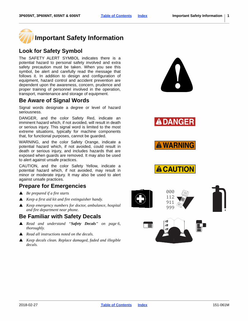
Look for Safety SymbolThe SAFETY ALERT SYMBOL indicates there is apotential hazard to personal safety involved and extrasafety precaution must be taken. When you see thissymbol, be alert and carefully read the message thatfollows it. In addition to design and configuration ofequipment, hazard control and accident prevention aredependent upon the awareness, concern, prudence andproper training of personnel involved in the operation,transport, maintenance and storage of equipment.
Be Aware of Signal WordsSignal words designate a degree or level of hazardseriousness.
DANGER, and the color Safety Red, indicate animminent hazard which, if not avoided, will result in deathor serious injury. This signal word is limited to the mostextreme situations, typically for machine componentsthat, for functional purposes, cannot be guarded.
WARNING, and the color Safety Orange, indicate apotential hazard which, if not avoided, could result indeath or serious injury, and includes hazards that areexposed when guards are removed. It may also be usedto alert against unsafe practices.
CAUTION, and the color Safety Yellow, indicate apotential hazard which, if not avoided, may result inminor or moderate injury. It may also be used to alertagainst unsafe practices.
Prepare for Emergencies Be prepared if a fire starts
Keep a first aid kit and fire extinguisher handy.
Keep emergency numbers for doctor, ambulance, hospitaland fire department near phone.
Be Familiar with Safety Decals Read and understand “Safety Decals” on page 6,
thoroughly.
Read all instructions noted on the decals.
Keep decals clean. Replace damaged, faded and illegibledecals.
2018-02-27 Table of Contents Index 151-061M

3P605NT, 3P606NT, 605NT & 606NT Table of Contents Index Important Safety Information 2
Wear Protective Equipment Wear protective clothing and equipment.
Wear clothing and equipment appropriate for the job.Avoid loose-fitting clothing.
Because prolonged exposure to loud noise can causehearing impairment or hearing loss, wear suitablehearing protection such as earmuffs or earplugs.
Because operating equipment safely requires your fullattention, avoid wearing entertainment headphones whileoperating machinery.
Handle Chemicals ProperlyAgricultural chemicals can be dangerous. Improper usecan seriously injure persons, animals, plants, soil andproperty.
Do not use liquid seed treatments with the 3P606NT or606NT.
Read and follow chemical manufacturer’s instructions.
Wear protective clothing.
Handle all chemicals with care.
Avoid inhaling smoke from any type of chemical fire.
Never drain, rinse or wash dispensers within 100 feet(30 m) of a freshwater source, nor at a car wash.
Store or dispose of unused chemicals as specified bychemical manufacturer.
Dispose of empty chemical containers properly. Lawsgenerally require power rinsing or rinsing three times,followed by perforation of the container to prevent re-use.
Avoid High Pressure Fluids(Model 605NT or 606NT only)
Escaping fluid under pressure can penetrate the skin,causing serious injury.
Avoid the hazard by relieving pressure beforedisconnecting hydraulic lines.
Use a piece of paper or cardboard, NOT BODY PARTS, tocheck for suspected leaks.
Wear protective gloves and safety glasses or goggles whenworking with hydraulic systems.
If an accident occurs, seek immediate medical attentionfrom a physician familiar with this type of injury.
2018-02-27 Table of Contents Index 151-061M

3P605NT, 3P606NT, 605NT & 606NT Table of Contents Index Important Safety Information 3
Use an Adequate TractorModel 3P605NT or 3P606NT only:
Ensure that the tractor is rated for, and correctly ballastedfor the drill’s 3-point loading. Check that drill plus ballastdoes not exceed the tractor’s capability.
Avoid transport with material loaded in boxes.
Model 605NT or 606NT only:
Ensure that the tractor weighs at least 2/3 (67%) of thedrill (including the weight of any Options and materials).
Avoid transport with material loaded in boxes.
Use A Safety Chain(Model 605NT or 606NT only)
Use a safety chain to help control drawn machineryshould it separate from tractor drawbar.
Use a chain with a strength rating equal to or greater thanthe gross weight of towed machinery.
Attach chain to tractor drawbar support or other specifiedanchor location. Allow only enough slack in chain topermit turning.
Replace chain if any links or end fittings are broken,stretched or damaged.
Do not use safety chain for towing.
Keep Riders Off MachineryRiders obstruct the operator’s view. Riders could bestruck by foreign objects or thrown from the machine.
Never allow children to operate equipment.
Keep all bystanders away from machine during operation.
Use Safety Lights and DevicesSlow-moving tractors and towed implements can createa hazard when driven on public roads. They are difficultto see, especially at night.
Use flashing warning lights and turn signals wheneverdriving on public roads.
Use lights and devices provided with implement
2018-02-27 Table of Contents Index 151-061M
3P605NT, 3P606NT, 605NT & 606NT Table of Contents Index Important Safety Information 4
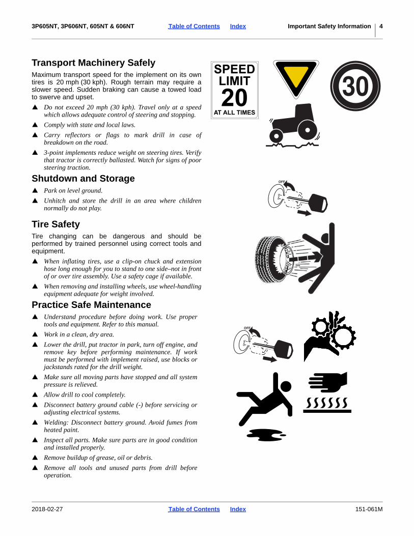
Transport Machinery SafelyMaximum transport speed for the implement on its owntires is 20 mph (30 kph). Rough terrain may require aslower speed. Sudden braking can cause a towed loadto swerve and upset.
Do not exceed 20 mph (30 kph). Travel only at a speedwhich allows adequate control of steering and stopping.
Comply with state and local laws.
Carry reflectors or flags to mark drill in case ofbreakdown on the road.
3-point implements reduce weight on steering tires. Verifythat tractor is correctly ballasted. Watch for signs of poorsteering traction.
Shutdown and Storage Park on level ground.
Unhitch and store the drill in an area where childrennormally do not play.
Tire SafetyTire changing can be dangerous and should beperformed by trained personnel using correct tools andequipment.
When inflating tires, use a clip-on chuck and extensionhose long enough for you to stand to one side–not in frontof or over tire assembly. Use a safety cage if available.
When removing and installing wheels, use wheel-handlingequipment adequate for weight involved.
Practice Safe Maintenance Understand procedure before doing work. Use proper
tools and equipment. Refer to this manual.
Work in a clean, dry area.
Lower the drill, put tractor in park, turn off engine, andremove key before performing maintenance. If workmust be performed with implement raised, use blocks orjackstands rated for the drill weight.
Make sure all moving parts have stopped and all systempressure is relieved.
Allow drill to cool completely.
Disconnect battery ground cable (-) before servicing oradjusting electrical systems.
Welding: Disconnect battery ground. Avoid fumes fromheated paint.
Inspect all parts. Make sure parts are in good conditionand installed properly.
Remove buildup of grease, oil or debris.
Remove all tools and unused parts from drill beforeoperation.
2018-02-27 Table of Contents Index 151-061M

3P605NT, 3P606NT, 605NT & 606NT Table of Contents Index Important Safety Information 5
Safety At All TimesThoroughly read and understand the instructions in thismanual before operation. Read all instructions noted onthe safety decals.
Be familiar with all drill functions.
Operate machinery from the driver’s seat only.
Do not leave drill unattended with tractor engine running.
Do not stand between the moving tractor and drill duringhitching.
Keep hands, feet and clothing away from power-drivenparts.
Wear snug-fitting clothing to avoid entanglement withmoving parts.
Make sure all persons are clear of working area.
2018-02-27 Table of Contents Index 151-061M

3P605NT, 3P606NT, 605NT & 606NT Table of Contents Index Important Safety Information 6
Safety DecalsSafety Reflectors and DecalsYour implement comes equipped with all lights, safetyreflectors and decals in place. They were designed tohelp you safely operate your implement.
Read and follow decal directions.
Keep lights in operating condition.
Keep all safety decals clean and legible.
Replace all damaged or missing decals. Order new decalsfrom your Great Plains dealer. Refer to this section forproper decal placement.
When ordering new parts or components, also requestcorresponding safety decals.
To install new decals:
1. Clean the area on which the decal is to be placed.
2. Peel backing from decal. Press firmly on surface,being careful not to cause air bubbles under decal.
Reflector: Slow Moving Vehicle (SMV)
At center of walkboard;1 total
See transport topic on page 20 or page 21.
Reflectors: Red
On rear face of walkboard, left and right ends;2 total
See transport topic on page 20 or page 21.
Reflectors: Amber
On side frames at walkboard ends;2 total
See transport topic on page 20 or page 21.
818-055C
32693
838-266C32693
838-266C32693
2018-02-27 Table of Contents Index 151-061M
3P605NT, 3P606NT, 605NT & 606NT Table of Contents Index Important Safety Information 7
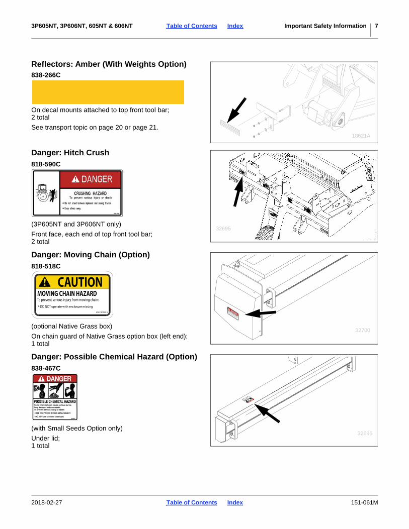
Reflectors: Amber (With Weights Option)838-266C
On decal mounts attached to top front tool bar;2 total
See transport topic on page 20 or page 21.
Danger: Hitch Crush
(3P605NT and 3P606NT only)
Front face, each end of top front tool bar;2 total
Danger: Moving Chain (Option)
(optional Native Grass box)
On chain guard of Native Grass option box (left end);1 total
Danger: Possible Chemical Hazard (Option)
(with Small Seeds Option only)
Under lid;1 total
18621A
818-590C
32695
818-518C
818-518C
DO NOT operate with inclosure missing
To prevent serious injury from moving chain:
MOVING CHAIN HAZARD
DANGER
32700
818-518C REV. B
DO NOT operate with enclosure missing
CAUTIONMOVING CHAIN HAZARDTo prevent serious injury from moving chain:
838-467C
32696
2018-02-27 Table of Contents Index 151-061M

3P605NT, 3P606NT, 605NT & 606NT Table of Contents Index Important Safety Information 8
Warning: Speed
On front face, upper front frame tube, left of center;1 total
See transport topic on page 20 or page 21.
Warning: Moving Parts (standard)
On front face, upper front frame tube, below gearbox;1 total
Warning: Moving Parts (Option)
(with Small Seeds Option only)
On front face, upper front frame tube, below gearbox;1 total
Warning: High Pressure Fluid
(605NT and 606NT only)On side frames, near cylinder;2 total
818-337C
32695
WARNINGEXCESSIVE SPEED
HAZARDTo Prevent Serious Injury or Death: Do NOT exceed 20 mph maximum transport speed. Loss of vehicle control and/or machine damage can result. 818-337C Rev. B
818-860C
32695
818-860C
32696
838-094C
32693
2018-02-27 Table of Contents Index 151-061M

3P605NT, 3P606NT, 605NT & 606NT Table of Contents Index Important Safety Information 9
Warning: Falling Hazard
On side frames at walkboard ends;2 total
See “Loading Seed” on page 25.
Warning: Clevis Adjustment
(605NT and 606NT only)On tongue cross-tube near turnbuckle;2 total
See “Height and Leveling the Drill” on page 17.
Warning: Crushing (Option)
(optional Native Grass box)On underside of lid;1 total
Caution: Tires Not A Step
(605NT and 606NT only)
On side frames above tires;2 total
Tires may be in light contact with ground, or off theground, when the drill is lowered.
838-102C32693
WARNINGTo avoid serious injury or death:
Watch your step when climbing ladder orwalking on walkboard.
838-102C
838-406C
32693
WARNING
838-611C
32700
818-398C
32693
2018-02-27 Table of Contents Index 151-061M

3P605NT, 3P606NT, 605NT & 606NT Table of Contents Index Important Safety Information 10
Caution: General
3P605NT and 3P606NT:On front face, upper front frame tube, right of center;1 total
605NT and 606NT:On front face, upper front frame tube, right end;
See “Important Safety Information” on page 1.
Caution: Tire Pressure and Torque
(605NT only, 2006- only)On rim of each end wheel with 9.5L 8-ply tires;2 total
Caution: Tire Pressure and Torque
(605NT 2007+, 606NT only)On rim of each end wheel with 700-15 LT tires;2 total
818-719C
32695
32693
838-258C32693
848-021C32693
CAUTIONTo Avoid Injury or Machine Damage from Improper TireInflation or Torquing of Wheel Bolts:
Maximum inflation pressure for tires is 60 psi.Torque wheel bolts to 85 lb-ft.
•• 848-021C REV. B
2018-02-27 Table of Contents Index 151-061M

3P605NT, 3P606NT, 605NT & 606NT Table of Contents Index Important Safety Information 11
NOTICE: Petroleum Products858-679C
(3P6006NT and 606NT only) On the left-hand ends ofeach seed box;1 per seed box
xxx
2018-02-27 Table of Contents Index 151-061M

3P605NT, 3P606NT, 605NT & 606NT Table of Contents Index Introduction 12
Introduction
Great Plains welcomes you to its growing family of newproduct owners. Your 6-Foot No-Till Drill has beendesigned with care and built by skilled workers usingquality materials. Proper setup, maintenance, and safeoperating practices will help you get years of satisfactoryuse from the machine.
Description of UnitThe 605NT and 606NT are towed seeding implements.This drill has a working width of 7.5 feet (1.9 m). The drillhas straight arm, double disc 05 or 06 Series openers.The opener discs make a seed bed, and seed tubesmounted between the discs place seed in the furrow.Press wheels following the opener discs close the furrowand gauge opener seeding depth. A T-handle on theopener body makes seeding depth adjustments.
The metering system is driven from the gauge wheel(3-point), or from the left end wheel (pull-type). Seedingrates are set by rate adjustment handles and a DriveType gearbox for the main seed box.
Intended UsageUse this implement to seed production-agriculture cropsin conventional or minimum tillage applications.
Models CoveredThis manual applies to Great Plains drill models:
Standard 3P605NT, 3P606NT, 605NT or 606NT Modelshave a main seed box. Native Grass and/or Small Seedscapability may be added.
Document Family
3P605NT-0975 9-row 7.5-inch (19.1 cm)
3P606NT-0975 9-row 7.5-inch (19.1 cm)
605NT-0975 9-row 7.5-inch (19.1 cm)
606NT-0975 9-row 7.5-inch (19.1 cm)
151-061M Operator Manual (this document)
151-061P 3P606NT, 606NT Parts Manual
151-122B Seed Rate Manual
Figure 13P606NT No-Till Drill
32704
Figure 2606NT No-Till Drill
32703
2018-02-27 Table of Contents Index 151-061M
3P605NT, 3P606NT, 605NT & 606NT Table of Contents Index Introduction 13
Using This ManualThis manual familiarizes you with safety, assembly,operation, adjustments, troubleshooting, andmaintenance. Read this manual and follow therecommendations to help ensure safe and efficientoperation.
Right-hand and left-hand as used inthis manual are determined by facingthe direction the machine will travelwhile in use unless otherwise stated.An orientation rose in some line art
illustrations shows the directions of: Up, Back, Left,Down, Front, Right.
Identifies an Economic (not a Safety) Risk:NOTICE provides a crucial point of information related to thecurrent topic. Read and follow the instructions to avoid damageto equipment and ensure desired field results.
This form sets off useful information related to thecurrent topic, or forestalls possiblemisunderstanding.
The information in this manual is current at printing.Some parts may change to assure top performance.
Owner AssistanceIf you need customer service or repair parts, contact aGreat Plains dealer. They have trained personnel, repairparts and equipment specially designed for Great Plainsproducts.
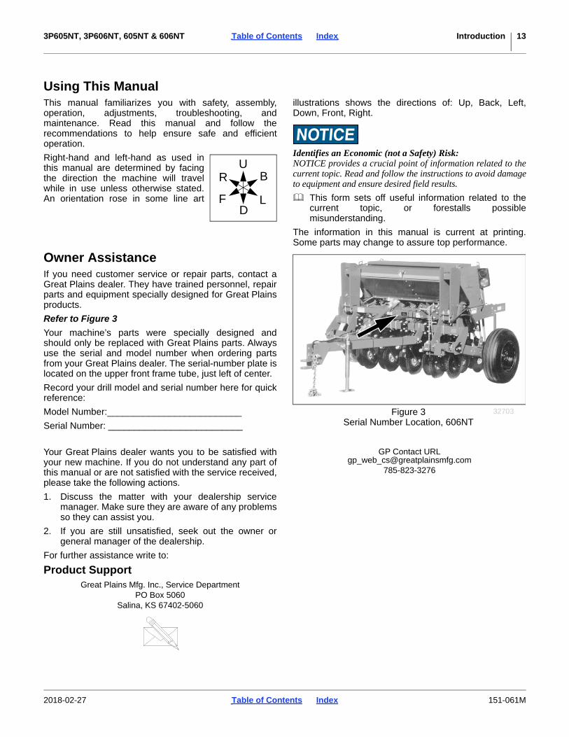
Refer to Figure 3
Your machine’s parts were specially designed andshould only be replaced with Great Plains parts. Alwaysuse the serial and model number when ordering partsfrom your Great Plains dealer. The serial-number plate islocated on the upper front frame tube, just left of center.
Record your drill model and serial number here for quickreference:
Model Number:__________________________
Serial Number: __________________________
Your Great Plains dealer wants you to be satisfied withyour new machine. If you do not understand any part ofthis manual or are not satisfied with the service received,please take the following actions.
1. Discuss the matter with your dealership servicemanager. Make sure they are aware of any problemsso they can assist you.
2. If you are still unsatisfied, seek out the owner orgeneral manager of the dealership.
For further assistance write to:
Product SupportGreat Plains Mfg. Inc., Service Department
PO Box 5060Salina, KS 67402-5060
GP Contact [email protected]
785-823-3276
U
DF
B
L
R
Figure 3Serial Number Location, 606NT
32703
2018-02-27 Table of Contents Index 151-061M

3P605NT, 3P606NT, 605NT & 606NT Table of Contents Index Preparation and Setup 14
Preparation and Setup
This section helps you prepare your tractor and drill foruse. Before using the drill in the field, you must hitch thedrill to a suitable tractor and also setup the drill.
Pre-Setup Checklist1. Verify that dealer pre-delivery is complete (page 73)
and optional accessories are installed (page 74).
2. Read and understand “Important SafetyInformation” on page 1.
3. Check that all working parts are moving freely, boltsare tight, and cotter pins are spread.
4. Check that all grease fittings are in place andlubricated. See “Lubrication and ScheduledMaintenance” on page 48.
5. Check that all safety decals and reflectors arecorrectly located and legible. Replace if damaged.See “Safety Decals” on page 6.
6. Inflate tires and tighten wheel bolts as at “TirePressures” on page 60.
Hitching Tractor to DrillHitching Model 3P605NT or 3P606NT
Crushing Hazard:You may be severely injured or killed by being crushedbetween the tractor and drill. Do not stand or place any part ofyour body between drill and moving tractor. Stop tractorengine and set park brake before installing the hitch pin.
Certain Machine Damage:Remove tractor draw bar before hitching the 3P605NT or3P606NT. The drill drive wheel will be damaged if drawbar isnot removed.
1. Raise or lower tractor 3-point arms as needed andpin lower arms to drill.
2. Pin upper arm to drill.
3. Slowly raise drill. Watch for cab interference.
4. Adjust top 3-point link so the top edge of drill box isparallel with the ground when drilling.
Do not use link to adjust opener depth. For openeradjustments, refer to “Opener Depth (Press WheelHeight)” on page 39. Set your tractor 3-point draftcontrol to Float position for planting.
Equipment Damage Risk:Due to interference with the gauge wheel assembly, drillmodels 3P605NT and 3P606NT are not compatible withGreat Plains accessory hitches CPH, PFH and SSH, nor withthe Great Plains hitch set-back kit.
2018-02-27 Table of Contents Index 151-061M

3P605NT, 3P606NT, 605NT & 606NT Table of Contents Index Preparation and Setup 15
Hitching Model 605NT or 606NT
Crushing Hazard:You may be severely injured or killed by being crushedbetween the tractor and drill. Do not stand or place any part ofyour body between drill and moving tractor. Stop tractorengine and set park brake before installing the hitch pin.
1. With drill lowered in field position and tongue jackmounted as shown in Figure 4, raise or lower tonguejack to level drill tongue.
Refer to Figure 5
2. With drill tongue level, adjust drill hitch on drill tongueto match your tractor-drawbar height. You can movethe hitch up or down or turn it over for a total of fourdifferent hitch heights.
3. When drill hitch matches tractor-drawbar height,hitch drill to tractor.
4. Securely attach drill safety chain to an anchor ontractor capable of pulling drill.
anchor-only
anchor-only
When hitching drill to a different tractor, check for adifference in drawbar heights. If heights are different,readjust hitch height accordingly.
Figure 4Jack in Parking Position
18473
Figure 5Clevis Hitch Height Adjustment
18544
159/32 in.38.8 cm
189/32 in.46.4 cm
1917/32 in.49.6 cm
2217/32 in.57.2 cm
Figure 6Pintle Hitch Height Adjustment
27216
1525/32 in.40.1 cm
1825/32 in.47.7 cm
201/32 in.50.9 cm
231/32 in.58.5 cm
2018-02-27 Table of Contents Index 151-061M
3P605NT, 3P606NT, 605NT & 606NT Table of Contents Index Preparation and Setup 16
Hydraulic Hose Hookup (605NT or 606NT)
High Pressure Fluid Hazard:Shut down tractor before making hydraulic connections. Onlytrained personnel should work with system hydraulics.Escaping fluid under pressure can have sufficient pressure topenetrate the skin causing serious injury. Use paper orcardboard, NOT BODY PARTS, to check for leaks. Wearprotective gloves and safety glasses or goggles when workingwith hydraulic systems. If an accident occurs, seek immediatemedical assistance from a physician familiar with this type ofinjury.
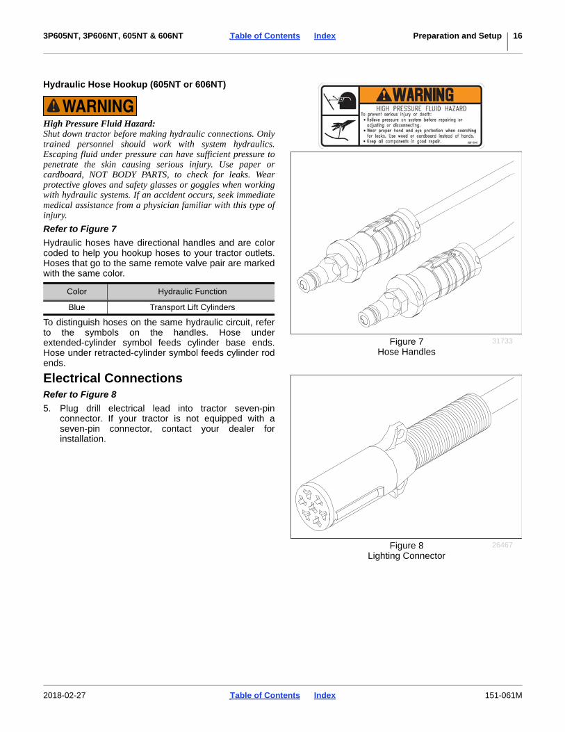
Refer to Figure 7
Hydraulic hoses have directional handles and are colorcoded to help you hookup hoses to your tractor outlets.Hoses that go to the same remote valve pair are markedwith the same color.
To distinguish hoses on the same hydraulic circuit, referto the symbols on the handles. Hose underextended-cylinder symbol feeds cylinder base ends.Hose under retracted-cylinder symbol feeds cylinder rodends.
Electrical ConnectionsRefer to Figure 8
5. Plug drill electrical lead into tractor seven-pinconnector. If your tractor is not equipped with aseven-pin connector, contact your dealer forinstallation.
Color Hydraulic Function
Blue Transport Lift Cylinders
Figure 7Hose Handles
31733
Figure 8Lighting Connector
26467
2018-02-27 Table of Contents Index 151-061M

3P605NT, 3P606NT, 605NT & 606NT Table of Contents Index Preparation and Setup 17
Height and Leveling the DrillHeight Setup: Model 3P605NT or 3P606NTRefer to Figure 9 and Figure 10
1. Initially adjust drill so opener tool bar runs 243/4 in. (62.9 cm) above ground when drill is lowered inthe field.
2. The drive wheel should be in the fourth mountinghole from the top (factory setting).
The drive may need to be adjusted due to groundconditions.
3. Level drill with top 3-point link.
Adjusting 3-Point Height
Raising the gauge wheel spindle provides deeper coulterdepth. Lowering the wheel provides shallower depth.
Do not lower coulters to aid in penetrating hard soil.Instead, increase coulter down-force (page 33). Thismay require adding optional weight (page 31).
Refer to Figure 10
1. Determine new coulter depth desired. With newdiscs, the axle holes provide these depths:
2. Raise drill, unless wheel is already off groundsufficiently to allow wheel spindle relocation.
3. Relax chain idlers.
4. Remove wheel bolts. Move spindle to new hole pair.Re-install wheel bolts.
5. Re-engage chain idlers.
Figure 9Initial Field Height,
3P605NT or 3P606NT
18546
243/4 in.62.9 cm
Figure 10Height Adjustment,
3P605NT or 3P606NT
18509
4
12
4
6
3
8
7
5
Hole No.(from top) Inches mm
1 3 1/ 2 in. 89 mm
2 2 7/ 8 in. 73 mm
3 2 3/ 8 in. 60 mm
4 (f) 1 7/ 8 in. 48 mm
5 1 3/ 8 in. 35 mm
6 7/ 8 in. 22 mm
7 3/ 8 in. 10 mm
8 1/ 4 in. 6 mmf. Factory setting. 32774G
Coulter Depth (n)
n. Depth is with new coulter blades.
2018-02-27 Table of Contents Index 151-061M

3P605NT, 3P606NT, 605NT & 606NT Table of Contents Index Preparation and Setup 18
Height Setup: Model 605NT or 606NTSet Tool Bar Height
Refer to Figure 11 and Figure 12
Tool bar height is controlled by a depth stopassembly on the left lift cylinder.
The suggested initial tool bar operating height is:243/4 in. (62.9 cm)
from the base of the opener tool bar to the ground, whenlowered in field conditions (opener discs in ground).
1. Use the tractor remote circuit to raise the drill to thefull extension of both lift cylinders. Hold the drillraised for several seconds to re-phase the cylinders.Remove any transport locks.
2. In field conditions, lower the drill to the desired toolbar height. Pull forward to put openers in ground.Set the remote to Neutral. Shut off the tractor.
3. Loosen the nut and bolt that secure the stopweldment to the cylinder rod.
4. Slide the weldment up the rod until it contacts thevalve actuator , then slide it up another 1/8 in. (3 mm). Tighten the bolt.
5. Start the tractor. Raise and lower the drill. Pullforward in ground. The lowering stops when theweldment moves the actuator a short distance.Shut off the tractor and verify the tool bar height.
If further adjustment is required, the drill heightchanges at approximately half the change inweldment position. For example, raising the drillanother 1/8 in. (3 mm) would require moving theweldment up another 1/4 in. (6 mm).
Level Model 605NT or 606NT
Refer to Figure 13
1. Use hitch turnbuckle to level drill.
2. Lower unit to take weight off of drill. Do not adjustwith unit in raised position.
3. Loosen jam nuts on hitch turnbuckle.
4. Turn turnbuckle to shorten or lengthen until top ofdrill frame is parallel to the ground being careful notto extend clevises beyond turnbuckle.
5. Righten jam nuts on turnbuckle.
2
1
Field Results Risk:Prior to first use, check tool bar height or the drill may runtoo deep. Model 606NT drills may be shipped with the depthstop valve actuator set to maximum depth. The actuatormust be adjusted to desired opener height prior to first use.
Figure 11Pull-Type Tool Bar Height
32681
1
2
12
1
34
5
4
3
5
Figure 12Cylinder Depth Stop
327126
Figure 13Pull-Type Turnbuckles
18513
6 6WARNING
2018-02-27 Table of Contents Index 151-061M

3P605NT, 3P606NT, 605NT & 606NT Table of Contents Index Operation Instructions 19
Operation Instructions
This section covers general operating procedures.Experience, machine familiarity and the followinginformation will lead to efficient operation and goodworking habits. Always operate farm machinery withsafety in mind.
Pre-Start Checklist
High Pressure Fluid Hazard:Escaping fluid under pressure can have sufficient pressure topenetrate the skin. Check all hydraulic lines and fittings beforeapplying pressure. Fluid escaping from a very small hole canbe almost invisible. Use paper or cardboard, not body parts,and wear heavy gloves to check for suspected leaks. If anaccident occurs, seek immediate medical assistance from aphysician familiar with this type of injury.
1. Carefully read “Important Safety Information”starting on page 1.
2. Lubricate drill per “Lubrication and ScheduledMaintenance” starting on page 48.
3. Check all tires for proper inflation. See “TirePressures” on page 60.
4. Check all bolts, pins and fasteners. See “TorqueValues Chart” on page 61.
5. Check drill for worn or damaged parts. Repair orreplace faulty parts before going to the field.
6. Check hydraulic hoses, fittings and cylinders forleaks. Repair or replace faulty parts before going tothe field.
7. Rotate both drive wheel to verify that the drive andmeters are working properly and free from foreignmaterial.
Falling Hazard:Watch your step when walking on drill steps and walkboard.Falling from drill could cause severe injury or death.
WARNINGTo avoid serious injury or death:
Watch your step when climbing ladder orwalking on walkboard.
838-102C
2018-02-27 Table of Contents Index 151-061M

3P605NT, 3P606NT, 605NT & 606NT Table of Contents Index Operation Instructions 20
Transporting 3P605NT or 3P606NTTransport considerations are different for 3-point andpull-type models. For pull-type, see page 21.
Use an Adequate Tractor (3-Point)
Loss of Control Hazard:Insufficient weight on tractor steering tires can dangerouslyreduce steering authority, particularly during acceleration andascending hills. You can lose directional control entirely,which could result in a major accident, serious injury, ordeath. Adding too much ballast could lead to brake or othermechanical failures, tire failures and loss of control.
Ensure that the tractor is rated for, and correctly ballastedfor the drill’s 3-point loading. Check that drill plus ballastdoes not exceed the tractor’s capability.
If the drill has accessory weight brackets, considermoving any tractor weights present to the tractor duringtransport.
Avoid transport with material loaded in boxes.
The total drill weight and center of gravity varyconsiderably with drill configuration and material load.See table below.
3P605NT or 3P606NT Example Weights
Continue at “Transport Cautiously” on page 25.
3-Point Drill Configuration Typical Weights
Boxes Empty Seed Loaded Seed + Weights*
Standard Drill (Main Seed only) 2280 lbs 3000 lbs 3780 lbs
1030 kg 1360 kg 1710 kg
Drill with Native Grass option 2580 lbs 3300 lbs 4080 lbs
1170 kg 1500 kg 1850 kg
Drill with Small Seeds option 2430 lbs 3150 lbs 3930 lbs
1100 kg 1430 kg 1780 kg
Drill with Native Grass & Small Seeds 2730 lbs 3450 lbs 4230 lbs
1240 kg 1560 kg 1920 kg
* 151-058A Weight Kit plus 6@ 100 pound tractor weights, approximately 780 lbs. 32774C* 151-058A Weight Kit plus 6 each 100 pound tractor weights, approximately 780
2018-02-27 Table of Contents Index 151-061M

3P605NT, 3P606NT, 605NT & 606NT Table of Contents Index Operation Instructions 21
Transporting 605NT or 606NTTransport considerations are different for 3-point andpull-type models. For 3-point, see page 20.
Use an Adequate Tractor (Pull-Type)
Loss of Control Hazard:Insufficient tractor weight can dangerously reduce steeringauthority, and increase braking loads beyond the capability ofthe tractor. You can lose directional control entirely, whichcould result in a major accident, serious injury, or death.
Ensure that the tractor weighs at least 2/3 (67%) of thedrill (including the weight of any Options and materials).
Avoid transport with material loaded in boxes.
The total drill weight varies considerably with drillconfiguration and material load. See table below.
2018-02-27 Table of Contents Index 151-061M

3P605NT, 3P606NT, 605NT & 606NT Table of Contents Index Operation Instructions 22
605NT or 606NT Example Weights
Use Transport Locks
Transport Hazard:Failure of hydraulic cylinders during transport causes drill todrop suddenly, which could lead to a serious accident, injuryor death. To prevent an accident, always install cylinder locksbefore transporting drill.
Before transporting the drill, check these items:
Cylinder Locks
Refer to Figure 14 or Figure 15, and Figure 16
A cylinder lock is provided for both gauge wheelhydraulic lift cylinders.
1. Raise drill completely. Set circuit to Neutral.
Pull-Type Drill Configuration Typical Weights
Boxes Empty Seed Loaded Seed + Weights*
Standard Drill (Main Seed only) 2700 lbs 3420 lbs 4200 lbs
1220 kg 1550 kg 1910 kg
Drill with Native Grass option 3000 lbs 3720 lbs 4500 lbs
1360 kg 1690 kg 2040 kg
Drill with Small Seeds option 2850 lbs 3570 lbs 4350 lbs
1290 kg 1620 kg 1970 kg
Drill with Native Grass & Small Seeds 3100 lbs 3820 lbs 4600 lbs
1410 kg 1730 kg 2090 kg
* 151-058A Weight Kit plus 6@ 100 pound tractor weights, approximately 780 lbs. 32774D* 151-058A Weight Kit plus 6 each 100 pound tractor weights, approximately 780
1
4
3
Figure 14: 2012+Lift Cylinder Lock Storage
361771
2018-02-27 Table of Contents Index 151-061M
3P605NT, 3P606NT, 605NT & 606NT Table of Contents Index Operation Instructions 23
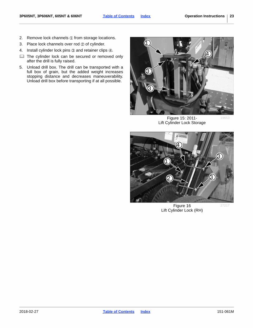
2. Remove lock channels from storage locations.
3. Place lock channels over rod of cylinder.
4. Install cylinder lock pins and retainer clips .
The cylinder lock can be secured or removed onlyafter the drill is fully raised.
5. Unload drill box. The drill can be transported with afull box of grain, but the added weight increasesstopping distance and decreases maneuverability.Unload drill box before transporting if at all possible.
Figure 15: 2011-Lift Cylinder Lock Storage
19653
3
1
3
4
1
2
3 4
Figure 16Lift Cylinder Lock (RH)
27217
1
4
3
32
2018-02-27 Table of Contents Index 151-061M
3P605NT, 3P606NT, 605NT & 606NT Table of Contents Index Operation Instructions 24
Disengage Lock-Out Hub
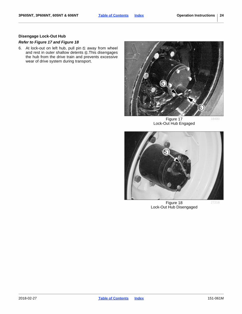
Refer to Figure 17 and Figure 18
6. At lock-out on left hub, pull pin away from wheeland rest in outer shallow detents .This disengagesthe hub from the drive train and prevents excessivewear of drive system during transport.
Figure 17Lock-Out Hub Engaged
18480
5
6
56
Figure 18Lock-Out Hub Disengaged
27218
5
2018-02-27 Table of Contents Index 151-061M

3P605NT, 3P606NT, 605NT & 606NT Table of Contents Index Operation Instructions 25
Transport CautiouslyKeep Clearance in Mind
Remember that the drill may be wider than the tractor.Allow safe clearance.
Observe Road Rules
Comply with all national, regional and local safety lawswhen traveling on public roads.
Reduce speed on rough roads.
Loading Seed
Possible Chemical Hazard:Take all prescribed material safety precautions.
Fully loaded with dense seed, the drill weighs anadditional 1155 lbs (529 kg). Include this weight whenchecking tractor capability.
The drill must be hitched for seed loading.
Load slightly more material than needed, becauseconsumption rates can vary between compartmentseven though the furrow rates are identical.
Main Seed Box Loading1. Check that all meter doors are positioned for the
seed size, and not set for clean-out. See “PositionSeed Cup Doors” in seed Rate Manual. If loadingprior to transport, set them to position 1 (smallestseed).
2. Install or remove optional seed plugs as desired forthe row spacing planned. Refer to Seed RateManual.
If loading prior to transport, and calibration has not yetbeen done, set Seed Rate Handle to 0. At 0, and with thedoors at 1, no seed can leak during transport.
3. The main seed box lid handle is also a latch. It needsto pivot up to release the lid.
4. Load seed evenly into compartments.
To reduce wear on unused boxes that may also bepresent:
• Remove final drive chain for Small Seed box.
• Remove any Native Grass chain.
Loading Native Grass Box1. The main seed box lid handle is also a latch. It needs
to pivot up to release the lid.
2. Load seed evenly into compartments.
3. Add 1/3 cup (80 mL) graphite seed lubricant on top ofthe loaded seed. In humid conditions, double or triplethis amount as needed.
Loading Small Seeds Box1. If loading prior to transport, and calibration has not
yet been done, set Seed Rate Handle to 0. At 0, noseed can leak during transport.
2. Take all necessary materials safety precautions if theseed is treated.
3. The Small Seeds lid is held closed by two externalrubber latches. Pull them up and to the rear torelease the lid.
4. Load seed evenly into compartments.
5. To reduce wear, remove main shaft drive chains formain seed boxes.
Loss of Control Hazard:Towing at high speeds or with a vehicle that is not heavyenough could lead to loss of vehicle control. Loss of vehiclecontrol could lead to serious road accidents, injury and death.To reduce the hazard, do not exceed 20 mph (30 kph).
Figure 19Native Grass Box Open
28362
123
1 2
3
2018-02-27 Table of Contents Index 151-061M
3P605NT, 3P606NT, 605NT & 606NT Table of Contents Index Operation Instructions 26
Field Operation1. Hitch drill to a suitable tractor (page 14).
For model 3P605NT or 3P606NT, continue at step 5.
2. Raise drill. Hold at raised for several seconds tore-phase lift cylinders. Set circuit to Neutral. Shut offtractor.
Refer to Figure 16 page 23 and Figure 15 on page 23
3. Remove transport lock channels from cylinder rods.Move them to storage and re-pin. See page 22.
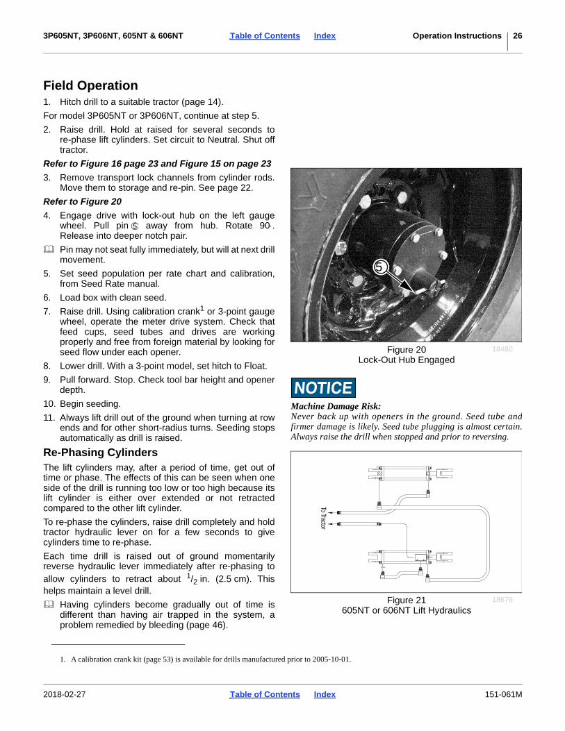
Refer to Figure 20
4. Engage drive with lock-out hub on the left gaugewheel. Pull pin away from hub. Rotate 90.Release into deeper notch pair.
Pin may not seat fully immediately, but will at next drillmovement.
5. Set seed population per rate chart and calibration,from Seed Rate manual.
6. Load box with clean seed.
7. Raise drill. Using calibration crank1 or 3-point gaugewheel, operate the meter drive system. Check thatfeed cups, seed tubes and drives are workingproperly and free from foreign material by looking forseed flow under each opener.
8. Lower drill. With a 3-point model, set hitch to Float.
9. Pull forward. Stop. Check tool bar height and openerdepth.
10. Begin seeding.
11. Always lift drill out of the ground when turning at rowends and for other short-radius turns. Seeding stopsautomatically as drill is raised.
Re-Phasing CylindersThe lift cylinders may, after a period of time, get out oftime or phase. The effects of this can be seen when oneside of the drill is running too low or too high because itslift cylinder is either over extended or not retractedcompared to the other lift cylinder.
To re-phase the cylinders, raise drill completely and holdtractor hydraulic lever on for a few seconds to givecylinders time to re-phase.
Each time drill is raised out of ground momentarilyreverse hydraulic lever immediately after re-phasing toallow cylinders to retract about 1/2 in. (2.5 cm). Thishelps maintain a level drill.
Having cylinders become gradually out of time isdifferent than having air trapped in the system, aproblem remedied by bleeding (page 46).
1. A calibration crank kit (page 53) is available for drills manufactured prior to 2005-10-01.
Machine Damage Risk:Never back up with openers in the ground. Seed tube andfirmer damage is likely. Seed tube plugging is almost certain.Always raise the drill when stopped and prior to reversing.
Figure 20Lock-Out Hub Engaged
18480
5
5
To Tractor
Figure 21605NT or 606NT Lift Hydraulics
18676
2018-02-27 Table of Contents Index 151-061M
3P605NT, 3P606NT, 605NT & 606NT Table of Contents Index Operation Instructions 27
Acremeter OperationAn electronic acremeter is standard on Models 3P606NTand 606NT. It is available as an accessory for Models3P605NT and 605NT. You may have any of threedifferent meter styles.
The acremeter counts shaft rotations whenever the shaftis rotating - this is with the drill lowered and in motion orduring crank operation. The meter is programmed todisplay rotations as acres or hectares, when using allrows, factory-specified tires and tire inflations.
Unusual conditions and/or non-standard rowspacings can cause the acremeter tally to vary fromactual acres planted.
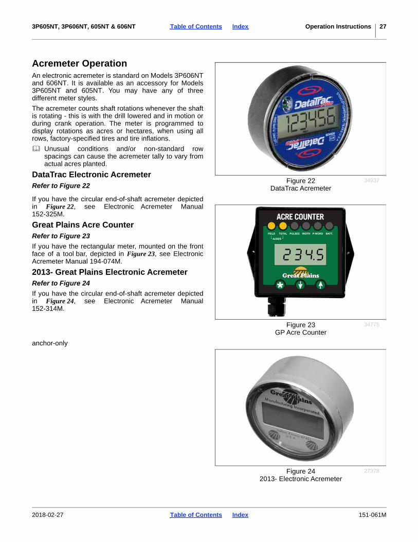
DataTrac Electronic AcremeterRefer to Figure 22
If you have the circular end-of-shaft acremeter depictedin Figure 22, see Electronic Acremeter Manual152-325M.
Great Plains Acre CounterRefer to Figure 23
If you have the rectangular meter, mounted on the frontface of a tool bar, depicted in Figure 23, see ElectronicAcremeter Manual 194-074M.
2013- Great Plains Electronic AcremeterRefer to Figure 24
If you have the circular end-of-shaft acremeter depictedin Figure 24, see Electronic Acremeter Manual152-314M.
anchor-only
Figure 22DataTrac Acremeter
34937
Figure 23GP Acre Counter
34775
Figure 242013- Electronic Acremeter
27378
2018-02-27 Table of Contents Index 151-061M

3P605NT, 3P606NT, 605NT & 606NT Table of Contents Index Operation Instructions 28
ParkingPerform the following steps when parking the drill for 36hours or less. Refer to “Storage”, to prepare forlong-term storage.
Parking Model 3P605NT or 3P606NT
1. Park drill on a level, solid area.
2. Lower 3-point hitch until drill is on the ground.
3. Unplug wiring harness from tractor. Do not allowharness end to rest on the ground.
4. Extend or retract the top link of the tractor until top 3-point pin is free. Remove pin.
5. Remove pins from lower links.
Parking Model 605NT or 606NT
1. Park drill on a level, solid area.
2. Lower drill until openers are resting on the ground.
3. Securely block tires to prevent rolling.
Refer to Figure 25 and Figure 26
4. Move jack to side stob near hitch. On older drills,rotate jack 90 degrees from storage position tousage position. Re-pin as shown in Figure 26. Ifground is soft, place a board or plate under jack.
On drills manufactured after August 1, 2006, astorage jack stob is located on top of the tongue.
5. Extend jack until tongue weight is off tractor drawbar.
Refer to Figure 27(which depicts the hitch of a pull-type drill; the hose caddy and connector storage cap are similar on 3-point drills, if they have hydraulics)
6. Set tractor remote circuit for Lift to Float. Unplughydraulic hoses. On newer drills, store the hoseends in the keyhole slots of the hose caddyplate.
7. Unplug wiring harness from tractor. On newer drills,insert the lighting connector into the bottom of theconnector cap . Rotate the plug as necessary untilthe keying tab clears a mating cutout in the capbase, then rotate the plug 90. Do not allow hoseends or cable ends to rest on the ground.
8. Remove hitch bolt and safety chain from tractordrawbar.
Figure 25Parking Jack Storage
24481
Figure 26Parking Jack Lowered
18473
12
3
4
5
Figure 27Hose and Connector Storage
36173
1 2
345
2018-02-27 Table of Contents Index 151-061M

3P605NT, 3P606NT, 605NT & 606NT Table of Contents Index Operation Instructions 29
StorageStore drill where children do not play. If possible, storethe drill inside for longer life.
1. Unload seed boxes. Thoroughly cleanseed-treatment residue from boxes and feed cups.See “Seed Clean-Out” on page 43.
2. Remove any dirt and debris that can hold moistureand cause corrosion.
3. Lubricate and adjust all roller chains.
4. Take special care to oil feed cup drive sprocket in itssquare bore.
5. Perform “Lubrication and ScheduledMaintenance” starting on page 48.
6. 605NT or 606NT: Grease exposed cylinder rods.
7. Inspect drill for worn or damaged parts. Make repairsand service during the off season.
8. Use spray paint to cover scratches, chips and wornareas on the drill to protect the metal.
9. Disconnect seed hoses from openers. Permanentelongation and premature cracking of hoses mayoccur if stored connected. Plug hose ends to preventpest entry into seed boxes.
10. Cover with a tarp if stored outside.
2018-02-27 Table of Contents Index 151-061M
3P605NT, 3P606NT, 605NT & 606NT Table of Contents Index Adjustments 30
Adjustments
To get full performance from your drill, you need anunderstanding of all component operations, and manyprovide adjustments for optimal field results. Some ofthese have been covered earlier in this manual.
Even if your planting conditions rarely change, someitems need periodic adjustment due to normal wear.
Planting Depth
Setting nominal planting depth, and achieving itconsistently, is affected by multiple adjustable drillfunctions. From greatest to least effect they are:
• Opener depth (press wheel height)
• Coulter depth
• Opener down-pressure (spring)
• Opener frame down-force (optional weights)
• Row unit down-pressure spring
• Opener (tool bar) height
• Disc blade adjustments (as discs wear)
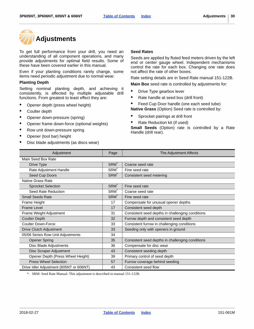
Seed Rates
Seeds are applied by fluted feed meters driven by the leftend or center gauge wheel. Independent mechanismscontrol the rate for each box. Changing one rate doesnot affect the rate of other boxes.
Rate setting details are in Seed Rate manual 151-122B.
Main Box seed rate is controlled by adjustments for:
• Drive Type gearbox lever
• Rate handle at seed box (drill front)
• Feed Cup Door handle (one each seed tube)Native Grass (Option) Seed rate is controlled by:
• Sprocket pairings at drill front
• Rate Reduction kit (if used)Small Seeds (Option) rate is controlled by a RateHandle (drill rear).
Adjustment Page The Adjustment Affects
Main Seed Box Rate
Drive Type SRM*
*. SRM: Seed Rate Manual: This adjustment is described in manual 151-122B.
Coarse seed rate
Rate Adjustment Handle SRM* Fine seed rate
Seed Cup Doors SRM* Consistent seed metering
Native Grass Rate
Sprocket Selection SRM* Fine seed rate
Seed Rate Reduction SRM* Coarse seed rate
Small Seeds Rate SRM* Fine seed rate
Frame Height 17 Compensate for unusual opener depths
Frame Level 17 Consistent seed depth
Frame Weight Adjustment 31 Consistent seed depths in challenging conditions
Coulter Depth 32 Furrow depth and consistent seed depth
Coulter Down-Force 33 Consistent furrow in challenging conditions
Drive Clutch Adjustment 33 Seeding only with openers in ground
05/06 Series Row Unit Adjustments 34
Opener Spring 35 Consistent seed depths in challenging conditions
Disc Blade Adjustments 36 Compensate for disc wear
Disc Scraper Adjustment 43 Consistent seeding depth
Opener Depth (Press Wheel Height) 39 Primary control of seed depth
Press Wheel Selection 57 Furrow coverage behind seeding
Drive Idler Adjustment (605NT or 606NT) 43 Consistent seed flow
2018-02-27 Table of Contents Index 151-061M

3P605NT, 3P606NT, 605NT & 606NT Table of Contents Index Adjustments 31
Frame Weight AdjustmentIn some challenging no-till conditions, the drill may nothave enough weight to enable consistent coulter soilpenetration. In such cases, additional weight may help.
An optional weight bracket kit is available. See page 59for ordering information. The kit includes two brackets .The kit itself adds 180 pounds (82 kg) to the drill. Itaccepts up to 600 pounds (272 kg) of standard tractorweights (300 pounds on each bracket), for a maximum of780 pounds (354 kg) additional weight.
See table at right for available down-force per coulter,with various drill and weight kit configurations.
Possible Transport Hazard:Re-check that the tractor or towing vehicle is adequate fortransport, particularly with a 3-point drill. Considertransporting without weights on the drill. A weight kit withmaximum weights can increase empty drill weight by 34%.
Tractor Damage/Field Results Risks:With weights installed, re-check that the tractor is adequate topull the drill afield. A tractor that was marginal with thestandard drill may provide inadequate performance withaccessory weights.
Always install equal weight on each bracket. Unbalancedweights causes uneven furrow and seeding depth across thedrill.
The maximum number of tractor weights may vary byweight style and supplier.
After installing weights, re-check frame height and level(page 17), coulter depth (page 32) and opener discdepth (page 39).
Figure 28Accessory Weight Brackets
32703
Drill Configuration 3P605NT 605NT(no seed loaded) 3P606NT 606NT
Standard Drill 253 lbs 294 lbs(no weight kit) 115 kg 133 kg
Standard Drill 287 lbs 328 lbsKit, plus 300 Pounds 130 kg 149 kg
Standard Drill 320 lbs 361 lbsKit, plus 600 Pounds 145 kg 164 kg
Drill w/ Small Seeds (SGS) 337 lbs 378 lbsKit, plus 600 Pounds 153 kg 171 kg
Drill w/ Native Grass (NG) 353 lbs 394 lbsKit, plus 600 Pounds 160 kg 179 kg
Drill with NG & SGS 370 lbs 405 lbsKit, plus 600 Pounds 168 kg 184 kg
32774E
Maximum Per Coulter
1
1
2018-02-27 Table of Contents Index 151-061M

3P605NT, 3P606NT, 605NT & 606NT Table of Contents Index Adjustments 32
Coulter AdjustmentsRefer to Figure 29
A no-till coulter , is mounted directly ahead of eachopener on the drill. The coulters cut through heavy trashand make a groove in the soil for the openers.
The coulter is designed to operate with its spring at fullextension. The spring is briefly compressed as the discencounters and rides over difficult obstructions.
Coulter DepthGreat Plains recommends operating at a tool bar heightof 243/4 in. (62.9 cm). Small adjustments may berequired for unusual seeding depths and as coulter discswear. If the coulters are not reaching desired depth (andthe springs are uncompressed), the drill may need moreweight (page 31).
Drill-wide coulter depth is controlled by tool bar height.The coulters are mounted on the drill frame. Groupcoulter cutting depth changes as the drill height is raisedand lowered.
When the opener frames are running level, theopener disc depth is 1/4 in. (6 mm) above coulterdepth.
Tool bar height is set by the tractor hitch for 3-point drills,and by cylinder depth stop (page 18) for pull-type drills.Individual Coulter Depth
Refer to Figure 29 and Figure 30
Individual coulter depth may be adjusted by raising andlowering the spring bar .
1. Determine the new coulter depth desired, and/or thedifference between that and the current depth.
2. Raise the drill until the coulter discs are just touchingthe ground. The press wheels are supporting somerow unit weight at this point.
3. Measure the current spring bar length , frombottom of tool bar to bottom of spring bar. Forreference, the factory setting is:
121/21/8 in. (31.83 mm)
Determine the new bar length required.
4. Loosen the clamp bolts . Use a mallet to adjust thebar height. Tighten the clamp bolts to Grade 5 torquespecification.
Figure 29Frame-Mounted Coulter
18645
1
3
4
2
1
2
Figure 30Coulter Spring Bar
32612
TO 9
C
36
5
Seeding Depth Risk:When adjusting coulter height, also reset opener spring force(page 35). Changing the coulter height changes the distancebetween row unit and spring attachment.3
5
5
6
2018-02-27 Table of Contents Index 151-061M

3P605NT, 3P606NT, 605NT & 606NT Table of Contents Index Adjustments 33
Coulter Down-ForceRefer to Figure 31
Coulter springs are preset at:10 in. (25.4 cm)
giving coulters an initial maximum operating force of400 pounds (181 kg). This setting is adequate for manydifficult no-till conditions.
Machine Damage Risk:Resetting coulter-spring length shorter than 93/4 in. (24.8 cm)inches may contribute to a premature failure of parts notcovered by warranty. If additional force is needed, add weightsto drill (page 31).
For lighter no-till conditions where rocks or otherobstructions are a problem, you can lengthen coultersprings to protect coulters from impact. Refer to table atright.
1. Measure current spring length.
2. Loosen or remove jam nut .
3. Rotate adjust nut to set spring length.
4. Tighten set jam nut.
Drive Clutch Adjustment(Models 606NT and 605NT only)
Refer to Figure 32
The main drive clutch on a pull-type drill is amechanical-release, jaw-style design. You may need toadjust the clutch for proper engagement anddisengagement.
When properly adjusted, the cam plates disengage theclutch jaws completely when the drill is raised. Whenlowered in field position, clutch jaws should be engaged.
To adjust, loosen bolts on clutch tab . Slide tab up ordown to change point at which cam plates meet. Whensatisfied with adjustment, tighten bolts on clutch tab.
Figure 31Coulter Spring Length
13990
Initial VerticalSpring Length
Inches mm Pounds Kilograms
10 1/ 2 in. 267 mm 175 lbs. 79 kg
10 1/ 4 in. 260 mm 300 lbs. 136 kg
(f) 10 in. 254 mm 400 lbs. 181 kg
9 3/ 4 in. 248 mm 525 lbs. 238 kgf. Factory setting. 32774J
Coulter Force
10.0 inches25.4 cm
2 87
2
7
8
Figure 32Drive Clutch
18482
1
2
3
1
2 3
2018-02-27 Table of Contents Index 151-061M

3P605NT, 3P606NT, 605NT & 606NT Table of Contents Index Adjustments 34
05/06 Series Row Unit AdjustmentsRefer to Figure 31 (which depicts an 06 Series row unit populated with most optional accessories)
From front to back, an 05/06 Series row unit (opener)can include the following capabilities (some optional):
1. Coulter (standard)This is not part of the opener, but is co-mounted withit on the tool bar. See “Coulter Adjustments” onpage 32.
2. Opener Discs (standard)Row-unit double disc openers create the seedbedfurrow. They have adjustments for spacing. See“Disc Blade Adjustments” on page 36.
3. Main Seed Hose (standard)Seed released by the metering cups is gravity fed bythe hose to the seed tube (not shown) between theopener discs. The hose and seed tube require noadjustments.
4. Down-Pressure Springs (standard)Two springs per row provide the primary force on theopener discs. The spring setting may needadjustment for challenging soil conditions and/or forchanges in coulter depth. See “Opener Spring” onpage 35
5. Inside Scraper (standard)This feature helps prevent soil buildup on the insidesurfaces of the opener discs, allowing them to meetsharply and prepare a crisp seed furrow. See “DiscScraper Adjustment” on page 37.
6. Seed Firmer (seed flap standard)A seed firmer confines seed bounce and can pressthe seed into the furrow. The standard seed flaprequires1 no adjustments. See “Seed FlapReplacement” on page 44. Optional Keeton® orSeed-Lok® firmers do have adjustments. See “SeedFirmer Adjustments” on page 38.
7. Option Seed Hose(s) (optional)If Native Grass or Small Seeds options are installed,there will be one or two additional seed hoses at oraft of the springs. The Small Seeds tube may bereversed if desired. See “Seed FirmerAdjustments” on page 38.
8. Press Wheel Height (standard)The T-handle is primary control for seeding depth.See “Opener Depth (Press Wheel Height)” onpage 39. The press wheels have no otheradjustments, but a choice of press wheel styles andsizes is available. Consult your dealer.
1. The seed flap may need to be shortened in length if an optional Keeton® or Seed-Lok® firmer is installed.
Machine Damage Risk:Never back up with row units on or in the ground. Seed tubeswill plug or be seriously damaged. Raise the drill for allreverse and short radius turns, and when stopping whilefacing up hill.
Figure 3306 Series Row Unit
32720
1
2
3
4
5
6
7
8
2018-02-27 Table of Contents Index 151-061M

3P605NT, 3P606NT, 605NT & 606NT Table of Contents Index Adjustments 35
Opener SpringOpener springs provide the down pressure necessary foropener discs to open a seed trench. The springs allowthe openers to float down into depressions and up overobstructions.
Each opener spring can be adjusted for down pressure.This is useful when planting in tractor tire tracks.
If coulter depth is altered for a row, the springpre-compression needs to be changed to compensatefor the change in row unit operating height.
Refer to Figure 34 and Figure 35
To adjust the pressure, remove “W” clip at bottom ofspring. Place “W” clip in a higher hole in spring rod formore pressure or in a lower hole for less pressure.
Use this adjustment only for a few rows, typically in tiretracks.
Do not set row force higher on all rows. Instead usecoulter adjustments (page 32) and frame weightadjustments (page 31).
Re-check drill level (page 17) after adjusting row force.
Figure 34Minimum Force
12102
“W”
Figure 35Maximum Force
12103
“W”
2018-02-27 Table of Contents Index 151-061M

3P605NT, 3P606NT, 605NT & 606NT Table of Contents Index Adjustments 36
Disc Blade AdjustmentsRaise drill and block it up or lock it up.
Opener Disc Spacing
Sharp Object Hazard:Be careful working around and handling disc blades. Weargloves. Edges of both new and well-worn blades can be sharp.
Opener disc angle and stagger is not adjustable, butdisc-to-disc spacing is, and may need attention as discsexperience normal wear. Spacers must be reset whenblades are replaced.
Refer to Figure 36
The ideal spacing causes the blades to be in contact forabout one inch. If you insert two pieces of paper betweenthe blades, the gap between them should be0 to 1.75 in. (0 to 4.4 cm)
If the blades do not touch, they should at least be closeenough so that a business card encounters some friction when passing between them.
If the contact region is significantly larger or the gap toowide, it needs to be adjusted by moving one or morespacer washers. If the contact region varies with bladerotation, one or both blades is likely bent and in need ofreplacement. If removing all spacers cannot bring theblades into contact, they are worn out and needreplacing.
Adjusting Disc Contact
Refer to Figure 37
1. Remove the bolt retaining the opener disc on oneside. Carefully remove the disc, noting how manyspacers are outside the disc and inside the disc.Do not lose the hub components and dust cap .
It is not necessary to remove the hub flange orbearing for this adjustment.
2. To reduce the spacing between the discs (the normalcase), move one spacer washer from the inside tothe outside of the disc. It may be necessary toloosen the scraper (page 37) to reduce disc-to-discspacing.
3. Re-assemble and check disc contact.
4. Re-adjust scraper.
Figure 36Checking Disc Contact
26451
1
2
3
2
Figure 37Adjusting Disc Spacers
26385
1
23
1
2018-02-27 Table of Contents Index 151-061M
3P605NT, 3P606NT, 605NT & 606NT Table of Contents Index Adjustments 37
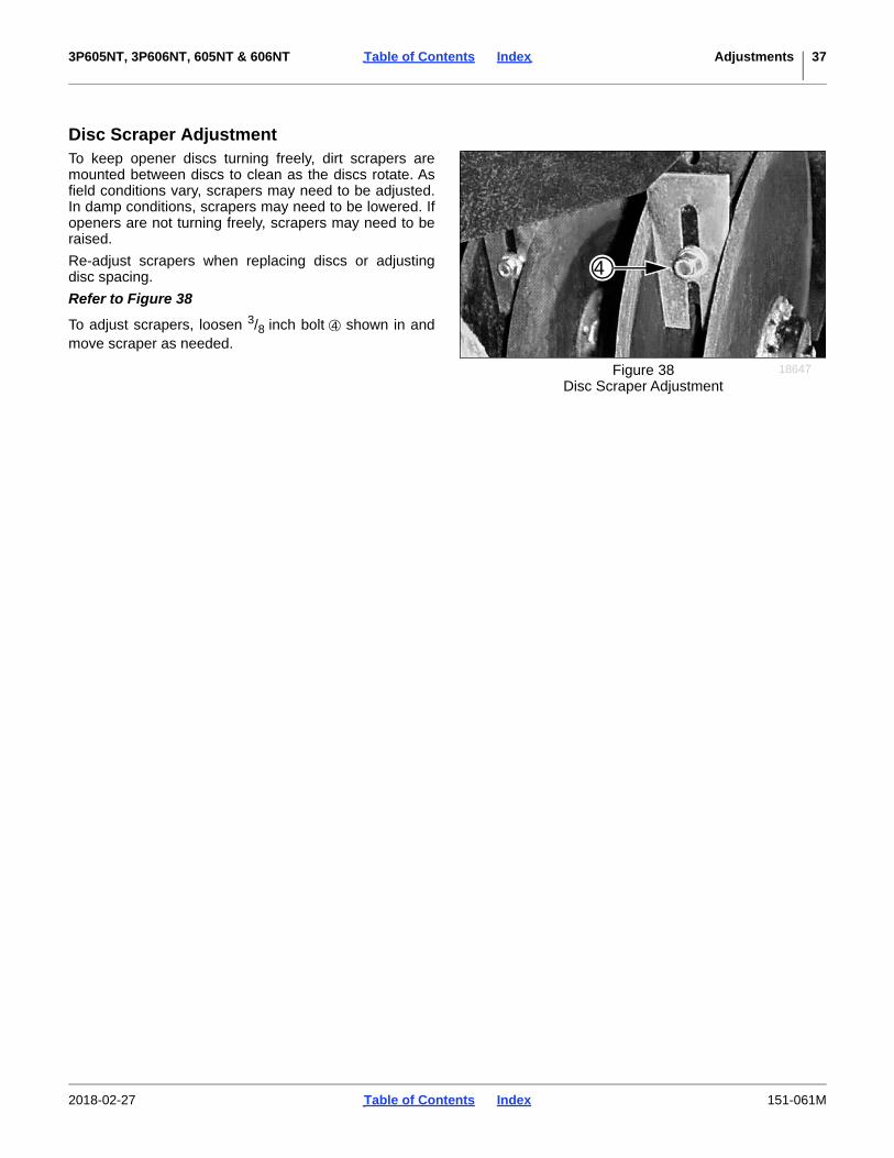
Disc Scraper AdjustmentTo keep opener discs turning freely, dirt scrapers aremounted between discs to clean as the discs rotate. Asfield conditions vary, scrapers may need to be adjusted.In damp conditions, scrapers may need to be lowered. Ifopeners are not turning freely, scrapers may need to beraised.
Re-adjust scrapers when replacing discs or adjustingdisc spacing.
Refer to Figure 38
To adjust scrapers, loosen 3/8 inch bolt shown in andmove scraper as needed.
Figure 38Disc Scraper Adjustment
18647
4
4
2018-02-27 Table of Contents Index 151-061M
3P605NT, 3P606NT, 605NT & 606NT Table of Contents Index Adjustments 38
Seed Firmer AdjustmentsStandard 05/06 Series row units include a seed flap.An optional Seed-Lok® or Keeton® seed firmer may beordered separately.
The seed flap requires no adjustment, but may need tobe replaced if worn, and may need to be shortened if anoptional seed firmer is added after initial delivery. Seealso “Seed Flap Replacement” on page 44.
Sharp Object Hazard:Use caution when making adjustments in this area. Row unitdisc blades may be sharp. To adjust the Keeton® Seed Firmer,lower the drill until the discs of the row units are resting on theground.
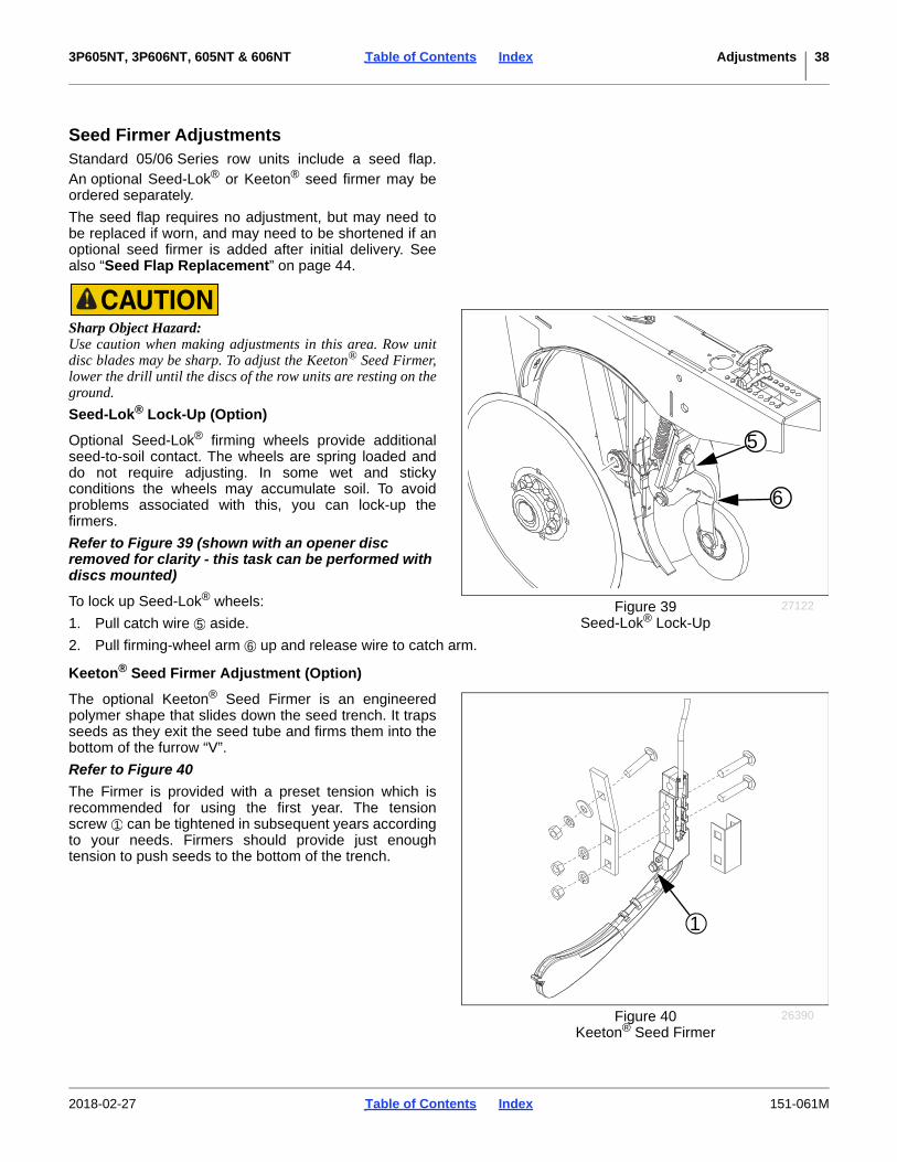
Seed-Lok® Lock-Up (Option)
Optional Seed-Lok® firming wheels provide additionalseed-to-soil contact. The wheels are spring loaded anddo not require adjusting. In some wet and stickyconditions the wheels may accumulate soil. To avoidproblems associated with this, you can lock-up thefirmers.
Refer to Figure 39 (shown with an opener disc removed for clarity - this task can be performed with discs mounted)
To lock up Seed-Lok® wheels:
1. Pull catch wire aside.
2. Pull firming-wheel arm up and release wire to catch arm.
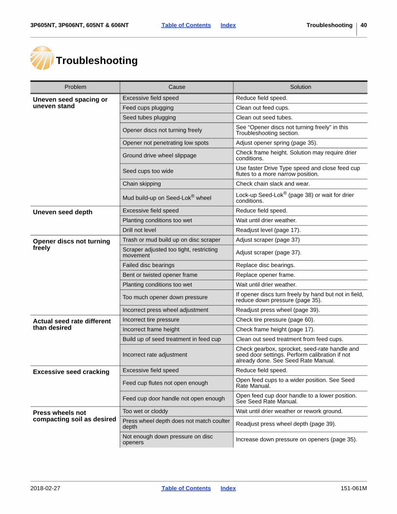
Keeton® Seed Firmer Adjustment (Option)
The optional Keeton® Seed Firmer is an engineeredpolymer shape that slides down the seed trench. It trapsseeds as they exit the seed tube and firms them into thebottom of the furrow “V”.
Refer to Figure 40
The Firmer is provided with a preset tension which isrecommended for using the first year. The tensionscrew can be tightened in subsequent years accordingto your needs. Firmers should provide just enoughtension to push seeds to the bottom of the trench.
5
6
Figure 39Seed-Lok® Lock-Up
27122
5
6
Figure 40Keeton® Seed Firmer
26390
1
1
2018-02-27 Table of Contents Index 151-061M

3P605NT, 3P606NT, 605NT & 606NT Table of Contents Index Adjustments 39
Small Seeds Tube Adjustment (Option)Refer to Figure 41
On a drill with the Small Seeds option, deeper seedplacement may be achieved by rotating the seed tubeto face forward.
This orientation is suggested only if the seed firmer is aseed flap. If a Keeton® or Seed-Lok® is present, seedfalls on the firmer and may be scattered rather thanplaced deeper.
Opener Depth (Press Wheel Height)A press wheel attached to each opener body controlsseeding depth . To maintain consistent depth, therelationship between the bottom of the opener discs andpress wheel is fixed upwardly by an adjustable stop oneach opener.
The press wheels also close the seed trench and gentlypress soil over seed. To provide consistent soil firming,press wheels are free to move down from normaloperating position. This maintains pressing action even ifopener discs encounter obstructions or hard soil.
To adjust, first raise openers slightly, then lift and slideT handles on top of openers Adjust all press wheels tothe same height.
• Each increment of the handle adjusts the seeding
depth by approximately 1/8 in. (6.3 mm). The range
is approximately 0 to 31/2 in. (0-89 mm) seedingdepth.
• For more shallow seeding, slide T handlesforward toward implement.
• For deeper seeding, slide T handles backwardaway from implement.
If moving the T handle backward doesn’t cause theopener to achieve desired depth, adjust the openerframe down-force (page 35).
Figure 41Small Seeds Tube
18618
1
1
Figure 42Adjusting Opener Depth
26441
1
2B
F1
2
F
B
2018-02-27 Table of Contents Index 151-061M
3P605NT, 3P606NT, 605NT & 606NT Table of Contents Index Troubleshooting 40
Troubleshooting
Problem Cause Solution
Uneven seed spacing or uneven stand
Excessive field speed Reduce field speed.
Feed cups plugging Clean out feed cups.
Seed tubes plugging Clean out seed tubes.
Opener discs not turning freely See “Opener discs not turning freely” in this Troubleshooting section.
Opener not penetrating low spots Adjust opener spring (page 35).
Ground drive wheel slippage Check frame height. Solution may require drier conditions.
Seed cups too wide Use faster Drive Type speed and close feed cup flutes to a more narrow position.
Chain skipping Check chain slack and wear.
Mud build-up on Seed-Lok® wheel Lock-up Seed-Lok® (page 38) or wait for drier conditions.
Uneven seed depth Excessive field speed Reduce field speed.
Planting conditions too wet Wait until drier weather.
Drill not level Readjust level (page 17).
Opener discs not turning freely
Trash or mud build up on disc scraper Adjust scraper (page 37)
Scraper adjusted too tight, restricting movement Adjust scraper (page 37).
Failed disc bearings Replace disc bearings.
Bent or twisted opener frame Replace opener frame.
Planting conditions too wet Wait until drier weather.
Too much opener down pressure If opener discs turn freely by hand but not in field, reduce down pressure (page 35).
Incorrect press wheel adjustment Readjust press wheel (page 39).
Actual seed rate different than desired
Incorrect tire pressure Check tire pressure (page 60).
Incorrect frame height Check frame height (page 17).
Build up of seed treatment in feed cup Clean out seed treatment from feed cups.
Incorrect rate adjustmentCheck gearbox, sprocket, seed-rate handle and seed door settings. Perform calibration if not already done. See Seed Rate Manual.
Excessive seed cracking Excessive field speed Reduce field speed.
Feed cup flutes not open enough Open feed cups to a wider position. See Seed Rate Manual.
Feed cup door handle not open enough Open feed cup door handle to a lower position. See Seed Rate Manual.
Press wheels not compacting soil as desired
Too wet or cloddy Wait until drier weather or rework ground.
Press wheel depth does not match coulter depth Readjust press wheel depth (page 39).
Not enough down pressure on disc openers Increase down pressure on openers (page 35).
2018-02-27 Table of Contents Index 151-061M
3P605NT, 3P606NT, 605NT & 606NT Table of Contents Index Troubleshooting 41
Boxes not emptying evenly Some boxes do not have same number of feed cups between each divider of bulkhead.
Load more material than required. Re-distribute when re-loading.
Main box seed cup door setting Set all doors the same, per seed size.
Seed plug(s) installed Remove seed plug(s).
Meter or tube blocked Clear blockage.
Press wheel or openers plugging
Planting conditions too wet Wait until drier weather.
Too much down pressure on openers Reduce down pressure on openers (page 35).
Backed up with drill in the ground Clean out and check for damage.
Failed disc bearings Replace disc bearings.
Scraper worn or damaged Replace scraper.
Feed cup sprockets locked up or twisted feed cup drive shaft
Foreign matter lodged in one or more feed cup sprockets Clean out feed cup sprockets. Use clean seed.
Dried liquid insecticide inside feed cupsRemove build up by disassembling each feed cup and scraping foreign substance from turn surfaces.
Coulters not going deep enough Not enough down pressure
Adjust coulters when a few rows are involved (page 33). Add weight when all rows are affected (page 31).
Row down pressure set too high (reducing weight available to coulters)
Reduce row down pressure to standard (page 35). Set coulters to prepare furrow more aggressively (page 32).
Coulters and drill going too deep
Coulters set too deep or spring force too high See page 32 for correct adjustment.
Incorrect press wheel adjustment Set press wheels to a shallower depth.
Coulters and openers plugging in no-till conditions
Drill at a slight angle to rows.
Small seeds box not emptying evenly Adjustable divider not set evenly Move adjustable divider to create more volume in
areas that run out first.
Chain fouling Debris in retainer clip Be sure retainer clip is facing opposite way of chain travel (page 47).
Acremeter inaccurate Excess wheel slippage Check frame height. If correct, solution may be to wait for drier conditions.
Passes misalignedCheck that planting passes are not leaving gaps (under-reporting area) or causing overlap (over-reporting area).
Wheel slippage is varying from nominal If variance is consistent, develop a correction factor for your conditions.
Check that acremeter is for your drill.
Activate display. Lower left corner must be:3P606NT: 913.0 Revs/ac (2256.1 Revs/ha)606NT: 995.0 Revs/ac (2458.7 Revs/ha)Contact dealer if otherwise.
Acremeter battery failing Replace acremeter (page 27). Unit is sealed and battery is not replaceable.
Problem Cause Solution
2018-02-27 Table of Contents Index 151-061M
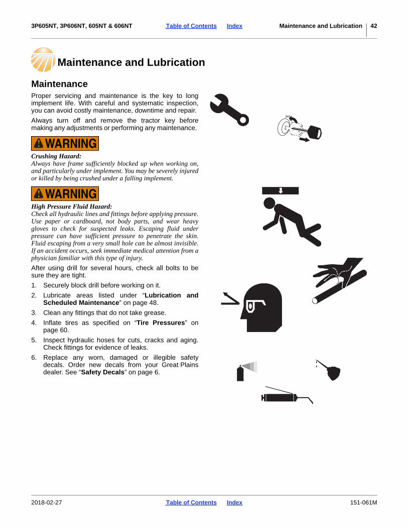
3P605NT, 3P606NT, 605NT & 606NT Table of Contents Index Maintenance and Lubrication 42
Maintenance and Lubrication
MaintenanceProper servicing and maintenance is the key to longimplement life. With careful and systematic inspection,you can avoid costly maintenance, downtime and repair.
Always turn off and remove the tractor key beforemaking any adjustments or performing any maintenance.
Crushing Hazard:Always have frame sufficiently blocked up when working on,and particularly under implement. You may be severely injuredor killed by being crushed under a falling implement.
High Pressure Fluid Hazard:Check all hydraulic lines and fittings before applying pressure.Use paper or cardboard, not body parts, and wear heavygloves to check for suspected leaks. Escaping fluid underpressure can have sufficient pressure to penetrate the skin.Fluid escaping from a very small hole can be almost invisible.If an accident occurs, seek immediate medical attention from aphysician familiar with this type of injury.
After using drill for several hours, check all bolts to besure they are tight.
1. Securely block drill before working on it.
2. Lubricate areas listed under “Lubrication andScheduled Maintenance” on page 48.
3. Clean any fittings that do not take grease.
4. Inflate tires as specified on “Tire Pressures” onpage 60.
5. Inspect hydraulic hoses for cuts, cracks and aging.Check fittings for evidence of leaks.
6. Replace any worn, damaged or illegible safetydecals. Order new decals from your Great Plainsdealer. See “Safety Decals” on page 6.
2018-02-27 Table of Contents Index 151-061M

3P605NT, 3P606NT, 605NT & 606NT Table of Contents Index Maintenance and Lubrication 43
Drive Idler Adjustment (605NT or 606NT)Two idler sprockets are located inside the left handgauge wheel arm. They should be readjusted after thefirst 100 acres (40 hectares) of drill use. From then on,readjust at the beginning of each season.
Refer to Figure 43
1. Loosen jam nut .
2. Move front idler sprocket on top of chain, tighteningchain, by screwing in adjustment stud .
3. Tighten jam nut to maintain idler position.
Do not over-tighten stud. Insufficient slack causesexcessive wear and premature chain failure.
Seed Clean-OutMain Box Clean-Out
Refer to Figure 44, which depicts the seed cup door handle in a normal operating position.
1. Set the Seed Rate Handle to zero (0). This movesthe seed cup sprockets out of the seed path.
2. Position a tarp or bucket under each row or set ofrows to be cleaned out.
3. At the seed cup for that row, pull the door handle out of the operating detent range, and swing it downto position .
4. Open the main seed box and use a small brush tosweep seed toward seed cups set to clean-out. Ifseed does not flow freely, inspect seed cup, hoseand seed tubes for obstructions.
5. If a vacuum cleaner is available, use it to removeresidual matter.
It is not necessary to operate the seed meter drive shaftfor clean-out. With the Seed Rate set to zero, nothingmoves inside the seed cups; however, an inspection ofthe flutes for excess wear and damage does requireshaft rotation.
Set the Seed Rate Handle to 100. Raise and lock-up thedrill. Turn the seed meter jackshaft with the calibrationcrank, while another person inspects the flutes from theopen seed boxes.
Figure 43Gauge Wheel Idler Adjustment
18481
1
21
2
Figure 44Seed Cup Clean-Out
26211
12
1
1
2
2018-02-27 Table of Contents Index 151-061M

3P605NT, 3P606NT, 605NT & 606NT Table of Contents Index Maintenance and Lubrication 44
Native Grass Box Clean-Out
If a suitable vacuum is available, open the Native Grassbox lid, and vacuum out remaining seed.
If too much seed remains for the vacuum, or no vacuumis available:
1. Raise and lock up the drill. Place a tarp under theNative Grass seed tubes.
2. Set the Native Grass (right gearbox) Drive Type to 4.Optionally install the smallest final Driven sprocket.
3. Install the calibration crank, and turn the drivesystem until no seed flows from Native Grass tubes.
4. Vacuum out any residual material from above.
Machine Damage Risk:Water wash-out is not recommended for the Native Grass box,particularly if seed lubricants have been used. Water maycause build-up of solidified residue. Filler material used innative grass mixes can also present problems.
Small Seeds Box Clean-Out
1. Open lid of each box and scoop out as much seed aspossible.
2. To recover remaining seed, place a collection tarpunder the small seeds tubes at the openers.
3. Raise drill.
4. Set seed rate handle to 100.
5. Rotate calibration crank or ground drive wheel untilno seed flows.
6. If a vacuum cleaner is available, remove anyresidual seed from top of meters.
Seed Flap ReplacementCurrent Drill Model FlapRefer to Figure 46
To replace a seed flap , use needle nose pliers orsimilar tool to grasp “T” top of flap. Pull upward toremove flap from metal bracket .
Push new seed flap down through metal bracketuntil flap snaps into place with “T” top resting on top ofbracket.
If a Seed-Lok® or Keeton® seed firmer is also installed, itmay be necessary to shorten the flap.
Figure 45Native Grass Box Open
28362
Figure 46Seed Tube Flap
31047
2
1
1
2
1 2
2018-02-27 Table of Contents Index 151-061M

3P605NT, 3P606NT, 605NT & 606NT Table of Contents Index Maintenance and Lubrication 45
Older Drill Model FlapRefer to Figure 47
To replace a seed flap use a needle nose or similartool and squeeze the tabs together. Pull plastic seedflap down out of metal bracket .
Push new seed flap up through metal bracket untiltabs on seed flap snap in place.
If a Seed-Lok® or Keeton® seed firmer is also installed, itmay be necessary to shorten the flap.
Figure 47Older Seed Tube Flap
18398
3
2
1
21
21 3
1 32
2018-02-27 Table of Contents Index 151-061M

3P605NT, 3P606NT, 605NT & 606NT Table of Contents Index Maintenance and Lubrication 46
Bleeding HydraulicsCheck that tractor hydraulic reservoir is full.
The drill lifting system is equipped with re-phasing typehydraulic cylinders that require a special procedure forbleeding air from the hydraulic circuits. Read and followthis procedure carefully. Re-phasing type cylinders willnot function properly with air in hydraulic circuit.
1. Check hydraulic fluid in tractor reservoir and fillreservoir to proper level. Drill-system capacity isabout 1 gallon (4.5 liters). Add fluid to system asneeded. A low reservoir level may draw air back intothe system, causing jerky or uneven cylindermovements.
2. With drill attached to tractor, jack drill up and supportframe at ends near gauge wheels.
3. With drill raised and supported, un-pin cylinders atboth gauge wheel arms and frame. Turn cylindersrod end up. Wire or otherwise safely support rodends higher than base ends.
4. With tractor engine idling, engage tractor hydraulicsto extend cylinder rods. When cylinder rods arecompletely extended, hold remote lever on for oneminute.
5. Retract cylinders. Extend cylinders again and holdremote lever on for one more minute. Repeat thisstep two more times to completely bleed system.
6. Re-pin cylinders to drill frame and gauge wheel armwith transport cylinder locks in place. If any air still istrapped in either cylinder, the cylinder will have aspongy, erratic movement and drill will not raiseevenly. If necessary, repeat bleeding process.
7. Refill tractor hydraulic fluid reservoir to its properlevel.
High Pressure Fluid Hazard:Escaping fluid under pressure can have sufficient pressure topenetrate the skin. Check all hydraulic lines and fittings beforeapplying pressure. Fluid escaping from a very small hole canbe almost invisible. Use paper or cardboard, not body parts,and wear heavy gloves to check for suspected leaks. If anaccident occurs, seek immediate medical assistance from aphysician familiar with this type of injury.
In order to prevent trapped air pockets, rod end mustbe higher than any other part of cylinder duringbleeding operation.
After the drill is raised, a slight settling will occur dueto the action of the re-phasing cylinders.
2018-02-27 Table of Contents Index 151-061M
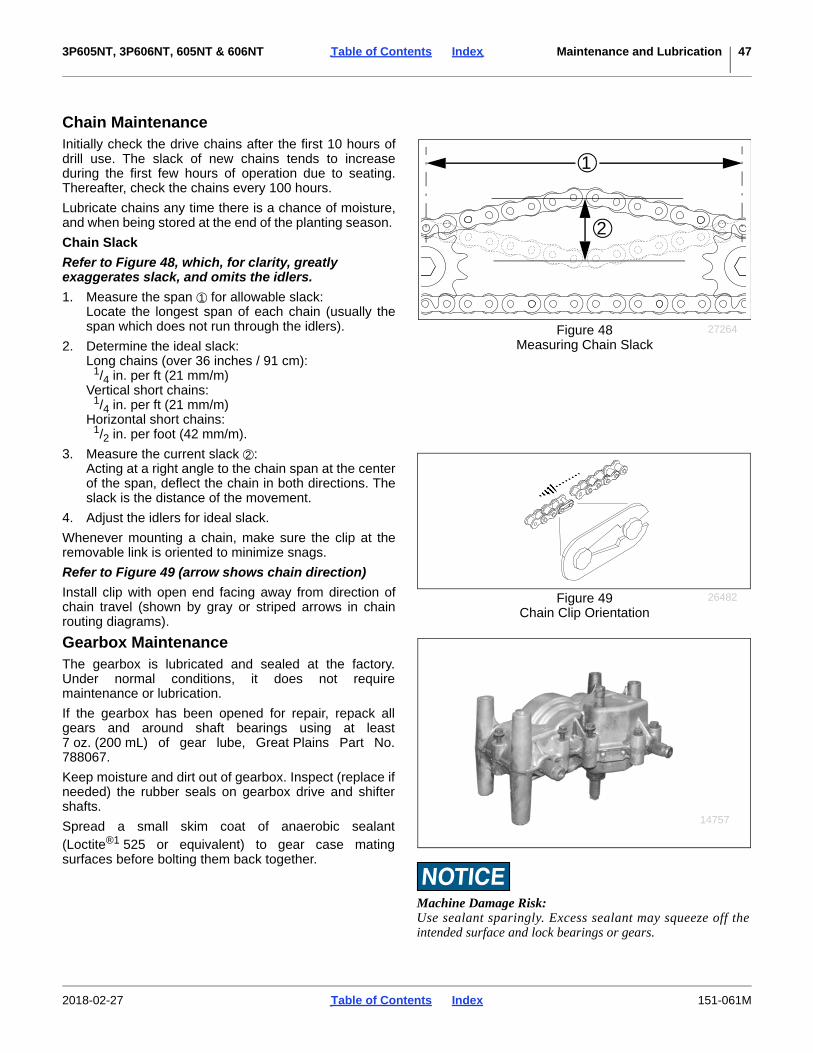
3P605NT, 3P606NT, 605NT & 606NT Table of Contents Index Maintenance and Lubrication 47
Chain MaintenanceInitially check the drive chains after the first 10 hours ofdrill use. The slack of new chains tends to increaseduring the first few hours of operation due to seating.Thereafter, check the chains every 100 hours.
Lubricate chains any time there is a chance of moisture,and when being stored at the end of the planting season.
Chain Slack
Refer to Figure 48, which, for clarity, greatly exaggerates slack, and omits the idlers.
1. Measure the span for allowable slack:Locate the longest span of each chain (usually thespan which does not run through the idlers).
2. Determine the ideal slack:Long chains (over 36 inches / 91 cm):
1/4 in. per ft (21 mm/m)Vertical short chains:
1/4 in. per ft (21 mm/m)Horizontal short chains:
1/2 in. per foot (42 mm/m).
3. Measure the current slack :Acting at a right angle to the chain span at the centerof the span, deflect the chain in both directions. Theslack is the distance of the movement.
4. Adjust the idlers for ideal slack.
Whenever mounting a chain, make sure the clip at theremovable link is oriented to minimize snags.
Refer to Figure 49 (arrow shows chain direction)
Install clip with open end facing away from direction ofchain travel (shown by gray or striped arrows in chainrouting diagrams).
Gearbox MaintenanceThe gearbox is lubricated and sealed at the factory.Under normal conditions, it does not requiremaintenance or lubrication.
If the gearbox has been opened for repair, repack allgears and around shaft bearings using at least7 oz. (200 mL) of gear lube, Great Plains Part No.788067.
Keep moisture and dirt out of gearbox. Inspect (replace ifneeded) the rubber seals on gearbox drive and shiftershafts.
Spread a small skim coat of anaerobic sealant(Loctite®1 525 or equivalent) to gear case matingsurfaces before bolting them back together.
Figure 48Measuring Chain Slack
27264
2
1
1
Figure 49Chain Clip Orientation
26482
2
14757
Machine Damage Risk:Use sealant sparingly. Excess sealant may squeeze off theintended surface and lock bearings or gears.
2018-02-27 Table of Contents Index 151-061M

3P605NT, 3P606NT, 605NT & 606NT Table of Contents Index Maintenance and Lubrication 48
Lubrication and Scheduled Maintenance
Coulter Pivots (3P606NT, 606NT)
1 grease bank zerk per coulter;9 total
Lubrication: GreaseAmount: until grease emerges at pivot
Coulter Pivots (3P605NT, 605NT)
1 zerk per coulter;9 total
Lubrication: GreaseAmount: until grease emerges
If the accessory Grease Bank (page 54) is installed,instill grease from the bank zerks.
Drive Shaft Clutch
2 zerks total
Lubrication: bearing greaseAmount: until grease emerges
Also smear grease on clutch engagement.
1. Loctite® is a registered trademark of Henkel Corporation.
8
50Multi-purpose
Multi-purpose
Multi-purpoIntervals(operating hours) at
Inspectio
25093
8
13880
8
18482
2018-02-27 Table of Contents Index 151-061M

3P605NT, 3P606NT, 605NT & 606NT Table of Contents Index Maintenance and Lubrication 49
Seed Cup Drive Shaft Sprocket
1 sliding sprocketType of Lubrication: OilQuantity: Coat thoroughly
Move the Seed Rate adjustment handle back and forth toget oil into the square bore. Perform this with seed boxempty, or handle may be difficult to set to 100.
Gauge Wheel Arms
2 zerks each arm,4 total
Type of Lubrication: GreaseQuantity: Until grease emerges
Small Seeds Shaft Bearings (Option)
1 zerk total
Type of Lubrication: GreaseQuantity: Until grease emerges
10
12126
15
18482
15
18082
2018-02-27 Table of Contents Index 151-061M

3P605NT, 3P606NT, 605NT & 606NT Table of Contents Index Maintenance and Lubrication 50
Drive Chains (Model: 3P605NT or 3P606NT)
Need photo survey for individual chain enumeration andslack values.
1 to 8 Chains Present:
Type of Lubrication: Chain LubeQuantity: Coat thoroughly
Standard Chains
• drive wheel to front left jackshaft
• jackshaft to gearbox input
• gearbox output (right) to main seed cup shaftOption Chains:
• gearbox output (left) to agitator/Native Grass (NG)jackshaft
• agitator/NG jackshaft to main box agitator and/or NGmeter shaft
• gearbox input (right, pass-through) to Small Seeds(SGS) front right jackshaft
• SGS front right jackshaft to rear jackshaft
• SGS rear jackshaft to meter shaft driveDrive Chains (Model: 605NT or 606NT)
Need photo survey for individual chain enumeration andslack values.
1 to 9 Chains Present:
Type of Lubrication: Chain LubeQuantity: Coat thoroughly
Standard Chains
• drive wheel to clutch shaft
• clutch shaft to jackshaft
• jackshaft to gearbox input
• gearbox output (right) to main seed cup shaftOption Chains:
• gearbox output (left) to agitator/Native Grass (NG)jackshaft
• agitator/NG jackshaft to main box agitator and/or NGmeter shaft
• gearbox input (right, pass-through) to Small Seeds(SGS) front jackshaft
• SGS front jackshaft to rear jackshaft
As Required
As Required
28291
28291
2018-02-27 Table of Contents Index 151-061M

3P605NT, 3P606NT, 605NT & 606NT Table of Contents Index Maintenance and Lubrication 51
• SGS rear jackshaft to meter shaft drive
Coulter Hubs
1 zerk per coulter;9 total
Type of Lubrication: Bearing greaseQuantity: Until resistance is felt
Wheel Bearings (3P605NT or 3P606NT)
2 races total
Type of Lubrication: Bearing greaseQuantity: Re-pack
Left Wheel Bearings (605NT or 606NT)
2 races total
Type of Lubrication: Bearing greaseQuantity: Re-pack
Seasonal
13879
Seasonal
32672
Seasonal
32589
2018-02-27 Table of Contents Index 151-061M
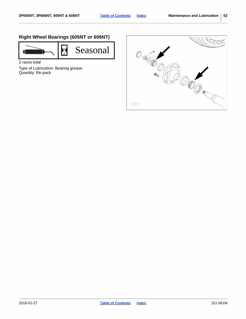
3P605NT, 3P606NT, 605NT & 606NT Table of Contents Index Maintenance and Lubrication 52
Right Wheel Bearings (605NT or 606NT)
2 races total
Type of Lubrication: Bearing greaseQuantity: Re-pack
Seasonal
32578
2018-02-27 Table of Contents Index 151-061M

3P605NT, 3P606NT, 605NT & 606NT Table of Contents Index Options 53
Options
Accessories are listed in alphabetical order. To order anaccessory, contact your Great Plains dealer.
AcremeterAn electronic acremeter is standard on Model 3P606NTand 606NT. If you need a meter with an alternate units ofmeasure, or have an older drill without an electronicacremeter, order one of the following parts.
See “Acremeter Operation” on page 27.
Calibration KitsField installation kits are available to upgrade drill Model3P605NT and 605NT. This adds a calibration crank,allowing operating of the meter shafts without needing torotate the gauge wheel tire.
Calibration cranks are standard on Model 3P606NTand 606NT.
Drill Model Units Part Number
3P605NT acres 891-005C
3P605NT hectares 891-006C
3P606NT acres 891-005C
3P606NT hectares 891-006C
605NT acres 891-007C
605NT hectares 891-008C
606NT acres 891-007C
606NT hectares 891-008C
27378
Drill Kit Part Number
3P605NT 3P605NT CALIBRATION KIT 152-303A
605NT 605NT CALIBRATION KIT 152-301A
23393
2018-02-27 Table of Contents Index 151-061M

3P605NT, 3P606NT, 605NT & 606NT Table of Contents Index Options 54
Carbide Disc ScraperSlotted scrapers are standard.
Optional carbide disc scrapers are spring-loaded andrequire no periodic adjustment. Scrapers are compatiblewith the standard seed flap and Seed-Lok®, but notKeeton®.
See “Carbide Disc Scraper Installation” on page 74.
Coulter BladesReplacement 17 in. (43 cm) blades are sold individually.
Grease BankA grease bank is standard on Model 3P606NT and606NT. It is available as an accessory for Model3P605NT and 605NT. This kit provides a single easilyaccessible point for supplying lubricant to all nine coulterpivots.
This kit is compatible with all drill models covered by thismanual.
Description Part Number
SPRING SCRAPER ASSEMBLY 121-781A
19000
Description Convolutions PartNumber
5/16 inch Fluted 50 820-018C3/4 inch Wavy 24 820-082C5/8 inch Wavy 24 820-116C
5/8 inch Wavy 20 820-156C31260
Fluted Wavy Turbo
Description Part Number
6’ GREASE BANK FIELD KIT 151-124A
25093
2018-02-27 Table of Contents Index 151-061M

3P605NT, 3P606NT, 605NT & 606NT Table of Contents Index Options 55
HitchesA clevis or pintle hitch must be specified on the originalorder for a new 606NT drill. An alternative hitch isavailable as an accessory for conversion in the field.
Main Seed Box AccessoriesAgitator (Main Seed)An optional agitator can be added to the main seed box.
It stirs the seed directly above the metering cups, helpingprevent bridging of light, fluffy seeds and separatingsoybeans that are sticky with innoculant.
If your drill is also equipped with a Native Grassattachment, the agitator is available without a drive.
Seed Tube Plug (Main Seeds)This plug stops seed flow from the main seed box abovethe meter. Order one per row to be set inactive.
See “Main Seed Row Shutoff” in Seed Rate Manual.
Drill Hitch Option Field Kit
605NT Pintle 177-534A
605NT Clevis 177-536A
606NT Pintle (81) 177-534A
606NT Clevis (83) 177-536A
32578
Description Part Number
Agitator with drive(for drills without Native Grass) 118-750A
Agitator without drive(for drills with native Grass) 118-751A
12682
Description Part Number
Fluted Feed Meter Plug 817-087C
26279
2018-02-27 Table of Contents Index 151-061M

3P605NT, 3P606NT, 605NT & 606NT Table of Contents Index Options 56
Series II Native Grass AttachmentThe native grass attachment is designed to seed fluffy,hard-to-plant grasses. It is available as an Option on theoriginal order (Option), or as a field-install kit whenordered with a field-installed Small Seeds Attachment(page 57).
See “Loading Seed” on page 25. For seed rates andadjustments, refer to “Native Grass Attachment” in theSeed Rate manual.
Seed LubricantsUse seed lubricants only in Native Grass planting.
See “Loading Seed” on page 25.
Native Grass Rate Reduction This kit is standard on Model 3P606NT and 606NTNative Grass (Options or field installed). The kit isavailable as an accessory for Model 3P605NT and605NT.
The Seed Rate Reduction Kit slows the Native Grassdrive system to 58% of standard chart rates. It includestwo sprockets, a storage/carrying case, and aninstallation and operators manual (202-583M).
Drill Configuration Option
3P605NT Native Grass Only -
3P605NT NG only, for a drill with SGS -
3P605NT Native Grass and Small Seeds -
3P606NT Native Grass Only (42)
3P606NT NG only, for a drill with SGS -
3P606NT Native Grass and Small Seeds (43)
605NT Native Grass Only -
3P605NT NG only, for a drill with SGS -
605NT Native Grass and Small Seeds -
606NT Native Grass Only (42)
606NT NG only, for a drill with SGS -
606NT Native Grass and Small Seeds (43)
32750
Description Part Number
Graphite (1 lb / 0.45 kg bottle) 821-042C
Graphite (5 pound / 2.3 kg jug) 821-060C
25477
Kit Description Part Number
3P605/605NT NG RATE REDUCTION 202-580A
25477
32753
2018-02-27 Table of Contents Index 151-061M

3P605NT, 3P606NT, 605NT & 606NT Table of Contents Index Options 57
Press Wheel SelectionThe base drill includes a choice of press wheels.Additional wheels are available, and all may befield-installed.
This manual does not list kit part numbers as theavailable wheels are often region-specific. Consult yourGreat Plains dealer.
Small Seeds AttachmentThe Small Seeds (SGS) attachment is designed to metervarious small seeds in row. It is driven independently ofother boxes on the drill. The standard attachmentincludes a drive system, 2.4 bushel box, meters andseed tubes.
Field upgrades to Small Seeds are available as:
For operation, see:“Loading Seed” on page 25 and “Small Seeds Rate” in Seed Rate Manual.
Drill Configuration Opt. Field Kit
3P605NT SGS only, for a drill without Native Grass - 133-131A
3P605NT SGS only, for a drill with Native Grass - 133-369A
3P605NT SGS and NG - 133-132A
3P606NT SGS only, for a drill without Native Grass (40) 133-131A
3P606NT SGS only, for a drill with Native Grass - 133-369A
3P606NT SGS and NG (43) 133-132A
605NT SGS only, for a drill without Native Grass - 133-124A
605NT SGS only, for a drill with Native Grass - 133-370A
605NT SGS and NG - 133-125A
606NT SGS only, for a drill without Native Grass (40) 133-124A
606NT SGS only, for a drill with Native Grass - 133-370A
606NT SGS and NG (43) 133-125A
326213262032617
32752
2018-02-27 Table of Contents Index 151-061M
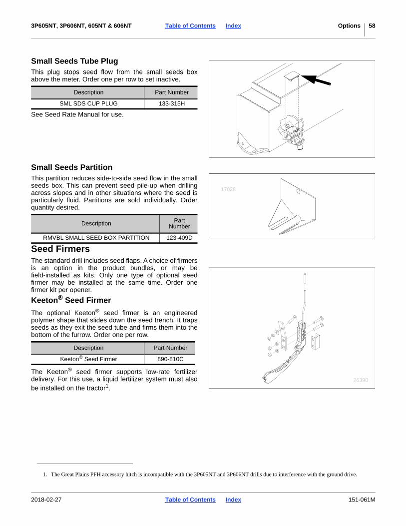
3P605NT, 3P606NT, 605NT & 606NT Table of Contents Index Options 58
Small Seeds Tube PlugThis plug stops seed flow from the small seeds boxabove the meter. Order one per row to set inactive.
See Seed Rate Manual for use.
Small Seeds PartitionThis partition reduces side-to-side seed flow in the smallseeds box. This can prevent seed pile-up when drillingacross slopes and in other situations where the seed isparticularly fluid. Partitions are sold individually. Orderquantity desired.
Seed FirmersThe standard drill includes seed flaps. A choice of firmersis an option in the product bundles, or may befield-installed as kits. Only one type of optional seedfirmer may be installed at the same time. Order onefirmer kit per opener.
Keeton® Seed Firmer
The optional Keeton® seed firmer is an engineeredpolymer shape that slides down the seed trench. It trapsseeds as they exit the seed tube and firms them into thebottom of the furrow. Order one per row.
The Keeton® seed firmer supports low-rate fertilizerdelivery. For this use, a liquid fertilizer system must alsobe installed on the tractor1.
Description Part Number
SML SDS CUP PLUG 133-315H
Description Part Number
RMVBL SMALL SEED BOX PARTITION 123-409D
17028
Description Part Number
Keeton® Seed Firmer 890-810C
1. The Great Plains PFH accessory hitch is incompatible with the 3P605NT and 3P606NT drills due to interference with the ground drive.
26390
2018-02-27 Table of Contents Index 151-061M

3P605NT, 3P606NT, 605NT & 606NT Table of Contents Index Options 59
Seed-Lok® Seed Firmer
The spring-loaded Seed-Lok® firming wheel pressesseed directly into the bottom of the seed bed. TheSeed-Lok® option provides more even emergence sinceseeds are planted and firmed at the same depth.
Seed-Lok® can be used on all configurations exceptNative Grass, unless the Native Grass seed tube isremoved during Seed-Lok® use.
For operations, see “Seed-Lok® Lock-Up (Option)” onpage 38.
Weight BracketsThe weight brackets are available as Options on theoriginal order or as field-installed accessories. Weightscan be added for additional penetration in no-tillconditions. The kit includes two weight brackets twoweight bracket adjustment legs , and mountinghardware. Also included are two decal mounts and twoamber reflector decals (not shown).
Each weight bracket accepts up to five standard 100pound (45 kg) “suitcase” style tractor weights.
The kits do not include weights.
See the Transporting topic starting on page 20 and“Frame Weight Adjustment” on page 31.
Description Part Number
Seed-Lok® kit 122-193K
12677
Drill Option Field Kit
605NT - 151-058A
3P605NT - 151-058A
606NT (66) 151-058A
3P606NT (66) 151-058A
32703
212
1
12
2018-02-27 Table of Contents Index 151-061M

3P605NT, 3P606NT, 605NT & 606NT Table of Contents Index Appendix A - Reference Information 60
Appendix A - Reference Information
Specifications and Capacities
Tire Information
Drill Model 3P605NT-0975 3P606NT-0975 605NT-0975 606NT-0975
Row Count 9 9
Row Spacing 7.5 in. (19.1 cm) 7.5 in. (19.1 cm)
Swath 67.5 in. (171.5 cm) 67.5 in. (171.5 cm)
Transport Width 6 ft. 1/2 in. (72.5 in., 184.2 cm) 8 ft 10 in. (106.0 in., 269.2 cm)
Length 5 ft 1 in. (61.0 in., 154.9 cm) 11 ft 5 in. (137.0 in., 348.0 cm)
Working Height 5 ft 1 in. (61.0 in., 154.9 cm) 5 ft 1 in. (61.0 in., 154.9 cm)
Transport Clearance Depends on tractor hitch 14.0 in. (35.6 cm)
Weight, Maximum, Empty¹ 2280 lbs. (1034 kg) 2700 lbs. (1225 kg)
Weight, Maximum, Full 4230 lbs. (1919 kg) 4600 lbs. (2087 kg)
Tongue Weight, Transport NA 366 lb (166 kg)
Tongue Weight, Field NA 416 lb (189 kg)
Main Seed Box Capacity 12 bu. (423 liter) 12 bu. (423 liter)
Native Grass Box Capacity 6 bu. (211 liter) 6 bu. (211 liter)
Small Seeds Box Capacity 1.44 bu. (51 liter) 1.44 bu. (51 liter)
Seed Box Agitator Optional in Main Seed box, Standard in Native Grass box
Min. Tractor HP Req.² 60 hp (45 Kw) 40 hp (30 Kw)
Hitch Type Category II Clevis or Pintle
Hydraulic Circuits Req. None 1
Tire Size 5.70L x 8 Lug Type 9.5L x 15 8-Ply 7.00-15 LT
Operating Depth 0 to 3.5 in. (0 to 8.9 cm) 0 to 3.5 in. (0 to 8.9 cm)
1. See “Transporting” topic for typical weights of various configurations.
2. Power requirements vary significantly with conditions and practices.
Tire Size Inflation Tire Warranty Information
5.70L-8 Lug Type,715 lb (324 kg) load rating
50 psi345 kPa
All tires are warranted by the original manufacturer of the tire. Tire warranty information is found online at the manufacturer’s websites listed below. For assistance or information, contact your nearest Authorized Farm Tire Retailer.Manufacturer WebsiteFirestone www.firestoneag.comGoodyear www.goodyearag.comTitan www.titan-intl.comBKT www.bkt-tires.comGleason www.gleasonwheel.com
7.00-15 LT2040 lb (925 kg) load rating
60 psi414 kPa
9.5L x 15 8-PlyRib Implement
44 psi303 kPa
2018-02-27 Table of Contents Index 151-061M

3P605NT, 3P606NT, 605NT & 606NT Table of Contents Index Appendix A - Reference Information 61
Torque Values Chart
94 6
25199m
BoltSize
Bolt Head IdentificationBoltSize
Bolt Head Identification
Grade 2 Grade 5 Grade 8 Class 5.8 Class 8.8 Class 10.9in-tpia N-mb N-m N-m mm x pitchc N-m N-m N-m1⁄4-20 7.4 11 16 M 5 X 0.81⁄4-28 8.5 13 18 M 6 X 1 7 11 155⁄16-18 15 24 33 M 8 X 1.25 17 26 365⁄16-24 17 26 37 M 8 X 1 18 28 393⁄8-16 27 42 59 M10 X 1.5 33 52 723⁄8-24 31 47 67 M10 X 0.75 39 61 857⁄16-14 43 67 95 M12 X 1.75 58 91 1257⁄16-20 49 75 105 M12 X 1.5 60 95 1301⁄2-13 66 105 145 M12 X 1 90 105 1451⁄2-20 75 115 165 M14 X 2 92 145 2009⁄16-12 95 150 210 M14 X 1.5 99 155 2159⁄16-18 105 165 235 M16 X 2 145 225 3155⁄8-11 130 205 285 M16 X 1.5 155 240 3355⁄8-18 150 230 325 M18 X 2.5 195 310 4053⁄4-10 235 360 510 M18 X 1.5 220 350 4853⁄4-16 260 405 570 M20 X 2.5 280 440 6107⁄8-9 225 585 820 M20 X 1.5 310 650 900
7⁄8-14 250 640 905 M24 X 3 480 760 1050
1-8 340 875 1230 M24 X 2 525 830 1150
1-12 370 955 1350 M30 X 3.5 960 1510 2100
11⁄8-7 480 1080 1750 M30 X 2 1060 1680 2320
11⁄8-12 540 1210 1960 M36 X 3.5 1730 2650 3660
11⁄4-7 680 1520 2460 M36 X 2 1880 2960 4100
11⁄4-12 750 1680 2730
13⁄8-6 890 1990 3230 a. in-tpi = nominal thread diameter in inches-threads per inch
13⁄8-12 1010 2270 3680 b. N· m = newton-meters
11⁄2-6 1180 2640 4290
11⁄2-12 1330 2970 4820
c. mm x pitch = nominal thread diameter in mm x thread pitch
Torque tolerance + 0%, -15% of torquing values. Unless otherwise specified use torque values listed above.
5.8 8.8 10.9
25199
ft-lbd ft-lb ft-lb ft-lb ft-lb ft-lb5.6 8 12
6 10 14 5 8 11
11 17 25 12 19 27
13 19 27 13 21 29
20 31 44 24 39 53
22 35 49 29 45 62
32 49 70 42 67 93
36 55 78 44 70 97
49 76 105 66 77 105
55 85 120 68 105 150
70 110 155 73 115 160
79 120 170 105 165 230
97 150 210 115 180 245
110 170 240 145 230 300
170 265 375 165 260 355
190 295 420 205 325 450
165 430 605 230 480 665
185 475 670 355 560 780
250 645 910 390 610 845
275 705 995 705 1120 1550
355 795 1290 785 1240 1710
395 890 1440 1270 1950 2700
500 1120 1820 1380 2190 3220
555 1240 2010
655 1470 2380
745 1670 2710
870 1950 3160d. ft-lb = foot pounds
980 2190 3560
3 5 7
2018-02-27 Table of Contents Index 151-061M
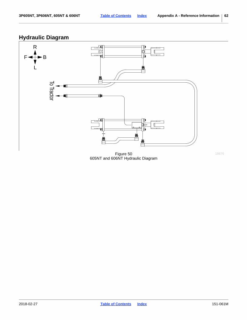
3P605NT, 3P606NT, 605NT & 606NT Table of Contents Index Appendix A - Reference Information 62
Hydraulic Diagram
To Tractor
F B
L
R
Figure 50605NT and 606NT Hydraulic Diagram
18676
2018-02-27 Table of Contents Index 151-061M
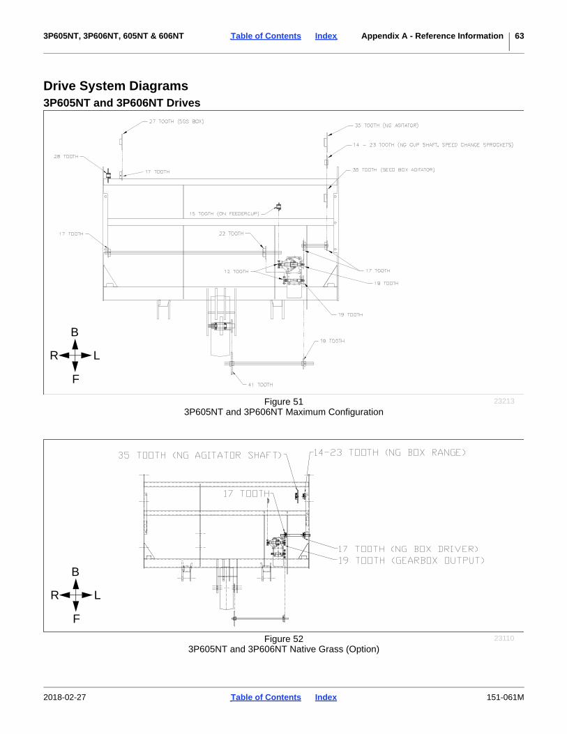
3P605NT, 3P606NT, 605NT & 606NT Table of Contents Index Appendix A - Reference Information 63
Drive System Diagrams3P605NT and 3P606NT Drives
R L
F
B
Figure 513P605NT and 3P606NT Maximum Configuration
23213
R L
F
B
Figure 523P605NT and 3P606NT Native Grass (Option)
23110
2018-02-27 Table of Contents Index 151-061M
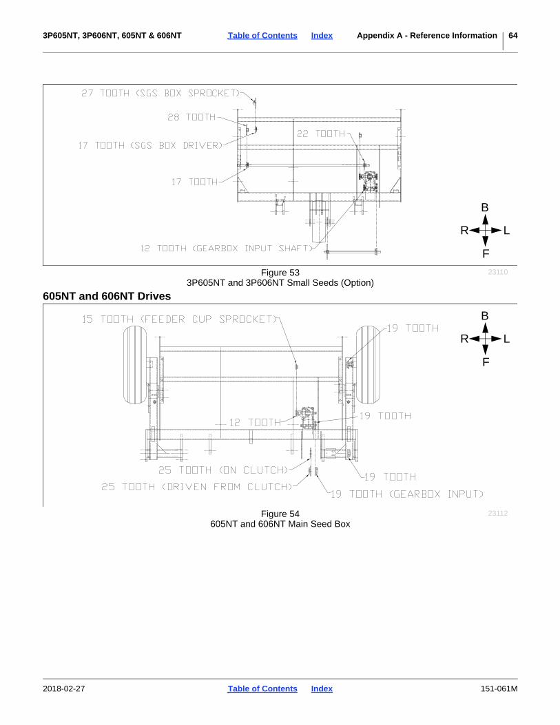
3P605NT, 3P606NT, 605NT & 606NT Table of Contents Index Appendix A - Reference Information 64
605NT and 606NT Drives
R L
F
B
Figure 533P605NT and 3P606NT Small Seeds (Option)
23110
R L
F
B
Figure 54605NT and 606NT Main Seed Box
23112
2018-02-27 Table of Contents Index 151-061M
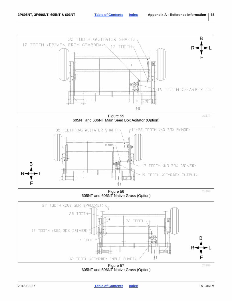
3P605NT, 3P606NT, 605NT & 606NT Table of Contents Index Appendix A - Reference Information 65
R L
F
B
Figure 55605NT and 606NT Main Seed Box Agitator (Option)
23112
R L
F
B
Figure 56605NT and 606NT Native Grass (Option)
23109
R L
F
B
Figure 57605NT and 606NT Native Grass (Option)
23109
2018-02-27 Table of Contents Index 151-061M

3P605NT, 3P606NT, 605NT & 606NT Table of Contents Index Appendix A - Reference Information 66
R L
F
B
Figure 58605NT and 606NT Maximum Configuration
23212
2018-02-27 Table of Contents Index 151-061M

3P605NT, 3P606NT, 605NT & 606NT Table of Contents Index Appendix A - Reference Information 67
Native Grass Drive Chain Routing3P605NT, 3P606NT, 605NT, 606NT
12I
12I
17T
17T16T
44P166P
12I
17I
35T
2018-02-27 Table of Contents Index 151-061M
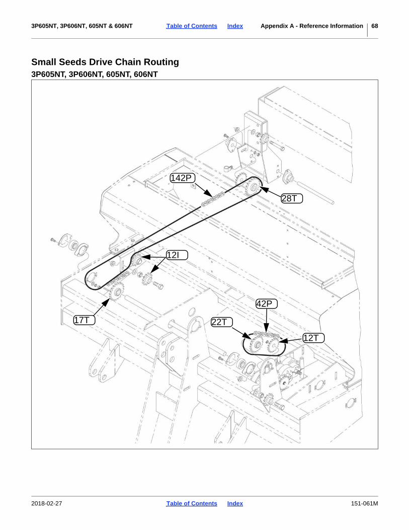
3P605NT, 3P606NT, 605NT & 606NT Table of Contents Index Appendix A - Reference Information 68
Small Seeds Drive Chain Routing3P605NT, 3P606NT, 605NT, 606NT
12T
22T
42P
28T
142P
17T
12I
2018-02-27 Table of Contents Index 151-061M

3P605NT, 3P606NT, 605NT & 606NT Table of Contents Index Appendix A - Reference Information 69
Agitator Drive Chain Routing3P605NT, 3P606NT. 605NT, 606NT
44P 12I16T
12I
68P
17T
17T
2018-02-27 Table of Contents Index 151-061M
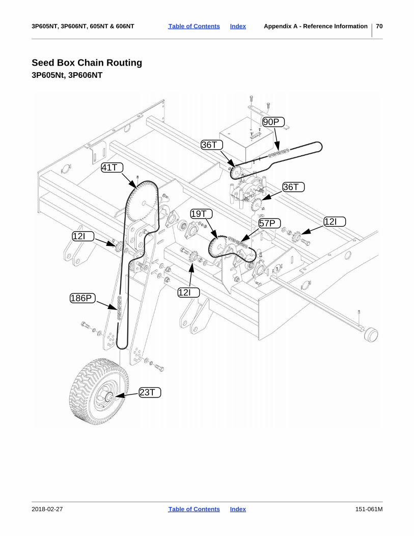
3P605NT, 3P606NT, 605NT & 606NT Table of Contents Index Appendix A - Reference Information 70
Seed Box Chain Routing3P605Nt, 3P606NT
19T
23T
57P
12I186P
12I
41T
12I
36T
36T
90P
2018-02-27 Table of Contents Index 151-061M

3P605NT, 3P606NT, 605NT & 606NT Table of Contents Index Appendix A - Reference Information 71
Drive Chain Routing605NT, 606NT
99P
25T
25T
19T
12I
63P
12I
12I
19T
12T
90P
2018-02-27 Table of Contents Index 151-061M
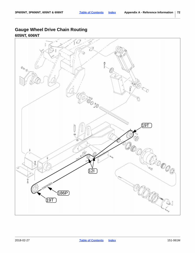
3P605NT, 3P606NT, 605NT & 606NT Table of Contents Index Appendix A - Reference Information 72
Gauge Wheel Drive Chain Routing605NT, 606NT
186P
19T
12I
19T
2018-02-27 Table of Contents Index 151-061M
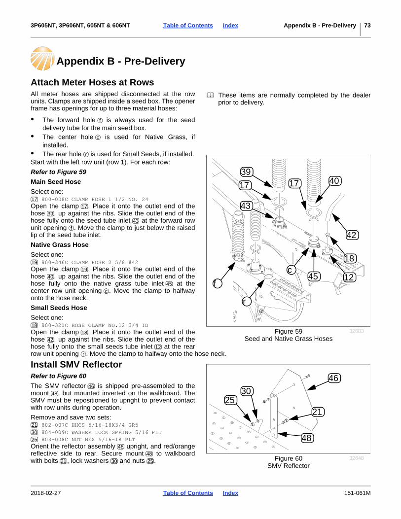
3P605NT, 3P606NT, 605NT & 606NT Table of Contents Index Appendix B - Pre-Delivery 73
Appendix B - Pre-Delivery
Attach Meter Hoses at RowsAll meter hoses are shipped disconnected at the rowunits. Clamps are shipped inside a seed box. The openerframe has openings for up to three material hoses:
• The forward hole is always used for the seeddelivery tube for the main seed box.
• The center hole is used for Native Grass, ifinstalled.
• The rear hole is used for Small Seeds, if installed.Start with the left row unit (row 1). For each row:
Refer to Figure 59
Main Seed Hose
Select one: 800-008C CLAMP HOSE 1 1/2 NO. 24
Open the clamp . Place it onto the outlet end of thehose , up against the ribs. Slide the outlet end of thehose fully onto the seed tube inlet at the forward rowunit opening . Move the clamp to just below the raisedlip of the seed tube inlet.
Native Grass Hose
Select one: 800-346C CLAMP HOSE 2 5/8 #42
Open the clamp . Place it onto the outlet end of thehose , up against the ribs. Slide the outlet end of thehose fully onto the native grass tube inlet at thecenter row unit opening . Move the clamp to halfwayonto the hose neck.
Small Seeds Hose
Select one: 800-321C HOSE CLAMP NO.12 3/4 ID
Open the clamp . Place it onto the outlet end of thehose , up against the ribs. Slide the outlet end of thehose fully onto the small seeds tube inlet at the rearrow unit opening . Move the clamp to halfway onto the hose neck.
Install SMV ReflectorRefer to Figure 60
The SMV reflector is shipped pre-assembled to themount , but mounted inverted on the walkboard. TheSMV must be repositioned to upright to prevent contactwith row units during operation.
Remove and save two sets: 802-007C HHCS 5/16-18X3/4 GR5 804-009C WASHER LOCK SPRING 5/16 PLT 803-008C NUT HEX 5/16-18 PLT
Orient the reflector assembly upright, and red/orangereflective side to rear. Secure mount to walkboardwith bolts , lock washers and nuts .
Figure 59Seed and Native Grass Hoses
32683
f
c
r
39
17
43
45 12
18
42
4017
These items are normally completed by the dealerprior to delivery.
f
c
r
1717
3943
f
1919
4045
c
1818
4212
r
Figure 60SMV Reflector
32648
25
46
30
21
48
4648
213025
4848
21 30 25
2018-02-27 Table of Contents Index 151-061M
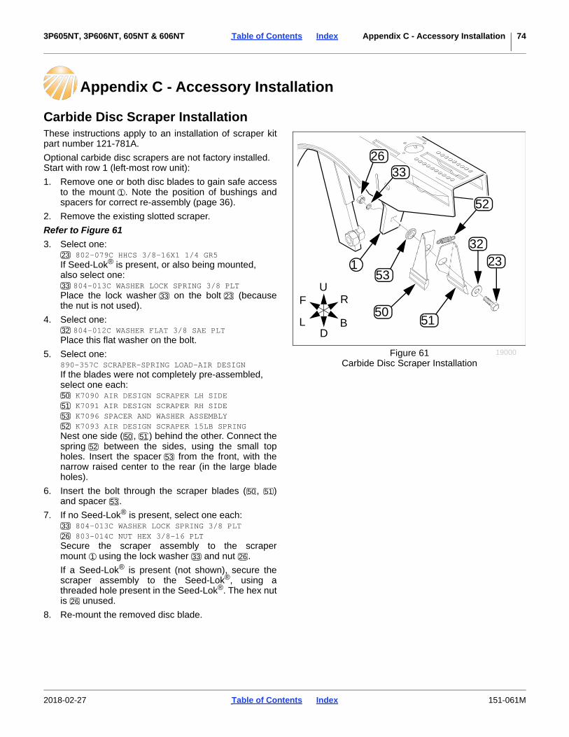
3P605NT, 3P606NT, 605NT & 606NT Table of Contents Index Appendix C - Accessory Installation 74
Appendix C - Accessory Installation
Carbide Disc Scraper InstallationThese instructions apply to an installation of scraper kitpart number 121-781A.
Optional carbide disc scrapers are not factory installed.Start with row 1 (left-most row unit):
1. Remove one or both disc blades to gain safe accessto the mount . Note the position of bushings andspacers for correct re-assembly (page 36).
2. Remove the existing slotted scraper.
Refer to Figure 61
3. Select one: 802-079C HHCS 3/8-16X1 1/4 GR5
If Seed-Lok® is present, or also being mounted,also select one:
804-013C WASHER LOCK SPRING 3/8 PLTPlace the lock washer on the bolt (becausethe nut is not used).
4. Select one: 804-012C WASHER FLAT 3/8 SAE PLT
Place this flat washer on the bolt.
5. Select one:890-357C SCRAPER-SPRING LOAD-AIR DESIGNIf the blades were not completely pre-assembled,select one each:
K7090 AIR DESIGN SCRAPER LH SIDE K7091 AIR DESIGN SCRAPER RH SIDE K7096 SPACER AND WASHER ASSEMBLY K7093 AIR DESIGN SCRAPER 15LB SPRING
Nest one side ( , ) behind the other. Connect thespring between the sides, using the small topholes. Insert the spacer from the front, with thenarrow raised center to the rear (in the large bladeholes).
6. Insert the bolt through the scraper blades ( , )and spacer .
7. If no Seed-Lok® is present, select one each: 804-013C WASHER LOCK SPRING 3/8 PLT 803-014C NUT HEX 3/8-16 PLT
Secure the scraper assembly to the scrapermount using the lock washer and nut .
If a Seed-Lok® is present (not shown), secure thescraper assembly to the Seed-Lok®, using athreaded hole present in the Seed-Lok®. The hex nutis unused.
8. Re-mount the removed disc blade.
Figure 61Carbide Disc Scraper Installation
19000
U
DL
R
B
F
1
2633
52
3223
5150
53
1
23
3333 23
32
50515352
50 5152
53
50 5153
3326
1 33 26
26
2018-02-27 Table of Contents Index 151-061M
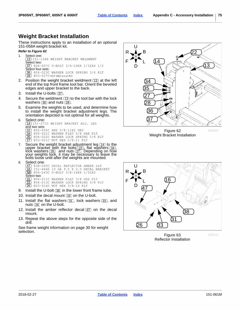
3P605NT, 3P606NT, 605NT & 606NT Table of Contents Index Appendix C - Accessory Installation 75
Weight Bracket InstallationThese instructions apply to an installation of an optional151-058A weight bracket kit.Refer to Figure 621. Select one:
151-134H WEIGHT BRACKET WELDMENT Select two:
806-007C U-BOLT 3/4-10X4 1/32X4 1/2Select four sets:
804-023C WASHER LOCK SPRING 3/4 PLT 803-027C NUT HEX 3/4-10 PLT
2. Position the weight bracket weldment at the leftend of the top front frame tool bar. Orient the bevelededges and upper bracket to the back.
3. Install the U-bolts .4. Secure the weldment to the tool bar with the lock
washers and nuts .5. Examine the weights to be used, and determine how
to install the weight bracket adjustment legs. Theorientation depicted is not optimal for all weights.
6. Select one: 151-271D WEIGHT BRACKET ADJ. LEG
and two sets: 802-055C HHS 5/8-11X2 GR5 804-021C WASHER FLAT 5/8 SAE PLT 804-022C WASHER LOCK SPRING 5/8 PLT 803-021C NUT HEX 5/8-11 PLT
7. Secure the weight bracket adjustment leg to theupper bracket with the bolts , flat washers ,lock washers and nuts . Depending on howyour weights lock, it may be necessary to leave thebolts loose until after the weights are mounted.
8. Select one: 838-265C DECAL REFLECTOR AMBER 2x9 151-446D 10 GA 9.5 X 2.5 DECAL BRACKET 806-263C U-BOLT 3/8-16X4 1/32X5
Select two 804-011C WASHER FLAT 3/8 USS PLT 804-013C WASHER LOCK SPRING 3/8 PLT 803-014C NUT HEX 3/8-16 PLT
9. Install the U-bolt in the lower front frame tube.10. Install the decal mount on the U-bolt.11. Install the flat washers , lock washers , and
nuts on the U-bolt.12. Install the amber reflector decal on the decal
mount.13. Repeat the above steps for the opposite side of the
drill.See frame weight information on page 30 for weightselection.
3435
2728
36
14
22
37
13
Figure 62Weight Bracket Installation
18562A
U
DF
B
L
R13
37
3628
13
37
1336 28
14
22343527
1422 34
35 27
38
313326
47
16
Figure 63Reflector Installation
18621A
U
DF
B
L
R471638
313326
38
16
31 3326
47
2018-02-27 Table of Contents Index 151-061M

3P605NT, 3P606NT, 605NT & 606NT Table of Contents Index Appendix C - Accessory Installation 76
38112
Warranty
Great Plains (a division of Great Plains Manufacturing, Inc.) warrants to theoriginal purchaser that this Great Plains unit will be free from defects in materialand workmanship for a period of one year from the first use date when used asintended and under normal service and conditions for personal use; ninety daysfor custom/commercial or rental use. This Warranty is limited to the replacementof any defective part by Great Plains and the installation by the dealer of anysuch replacement part. Great Plains reserves the right to inspect any equipmentor part which are claimed to have been defective in material or workmanship.
The following items and/or conditions are not covered under warranty:failures resulting from abuse or misuse of the equipment, failures occurring as aresult of accidental damage or acts of God, failures resulting from alterations ormodifications, failures caused by lack of normal maintenance as outlined in theoperator’s manual, repairs made by non-authorized personnel, items replaced orrepaired due to normal wear (such as wear items and ground engagingcomponents), repeat repair due to improper diagnosis or repair by the dealer,temporary repairs, service calls and/or mileage to and from customer location,overtime premium, or unit hauling expenses. The warranty may be voided if theunit is towed at speeds in excess of 20 miles per hour (32 kilometers per hour),or is used in soils with rocks, stumps, or other obstructions.
Great Plains reserves the right to make changes in materials or design of theproduct at any time without notice. The warranty shall not be interpreted torender Great Plains liable for damages of any kind, direct or consequential orcontingent to property. Furthermore, Great Plains shall not be liable for damagesresulting from any cause beyond its control. This warranty does not extend tocrop loss, losses caused by planting or harvest delays or any expense or loss oflabor, supplies, rental machinery, or for any other reason.
No other warranty of any kind whatsoever express or implied, is made withrespect to this sale; and all implied warranties of merchantability and fitness fora particular purpose which exceed the obligations set forth in this writtenwarranty are hereby disclaimed and excluded from this sale.
This warranty is not valid unless the unit is registered with Great Plains within10 days from the date of the original purchase.
2018-02-27 Table of Contents Index 151-061M
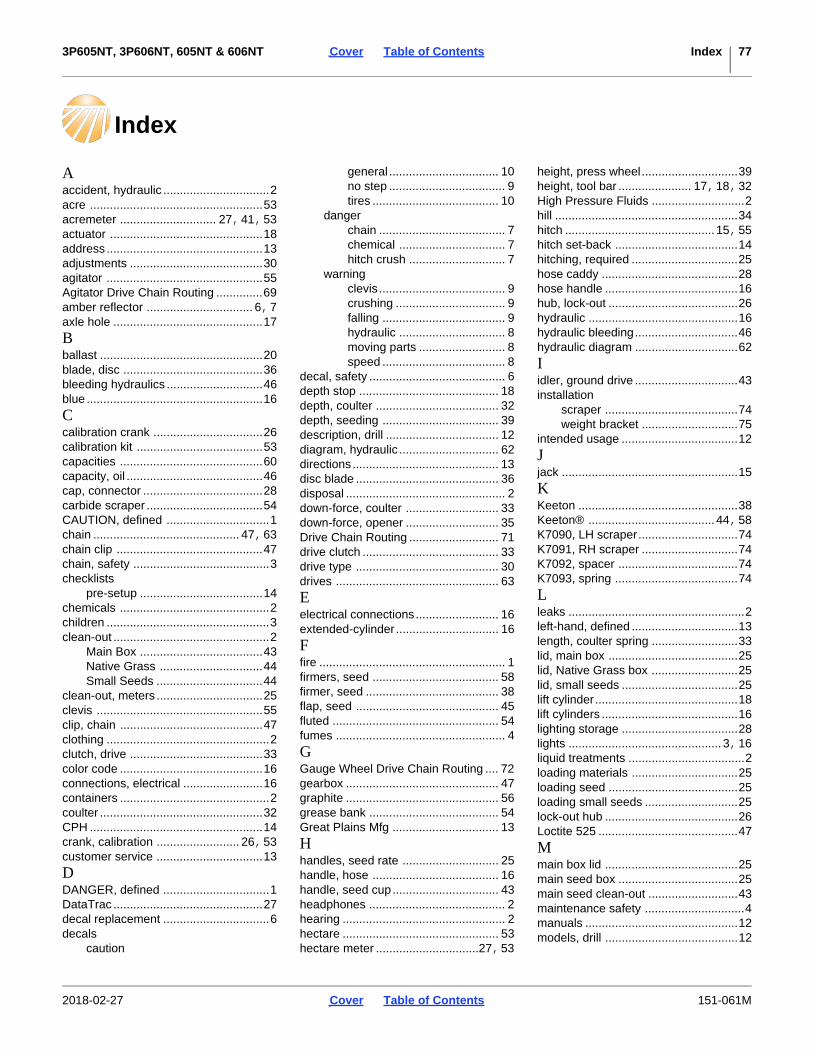
3P605NT, 3P606NT, 605NT & 606NT Cover Table of Contents Index 77
Index
Aaccident, hydraulic ................................2acre ....................................................53acremeter ............................. 27,41,53actuator ..............................................18address ...............................................13adjustments ........................................30agitator ...............................................55Agitator Drive Chain Routing ..............69amber reflector ................................ 6,7axle hole .............................................17
Bballast .................................................20blade, disc ..........................................36bleeding hydraulics .............................46blue .....................................................16
Ccalibration crank .................................26calibration kit ......................................53capacities ...........................................60capacity, oil .........................................46cap, connector ....................................28carbide scraper ...................................54CAUTION, defined ...............................1chain ............................................ 47,63chain clip ............................................47chain, safety .........................................3checklists
pre-setup .....................................14chemicals .............................................2children .................................................3clean-out ...............................................2
Main Box .....................................43Native Grass ...............................44Small Seeds ................................44
clean-out, meters ................................25clevis ..................................................55clip, chain ...........................................47clothing .................................................2clutch, drive ........................................33color code ...........................................16connections, electrical ........................16containers .............................................2coulter .................................................32CPH ....................................................14crank, calibration ......................... 26,53customer service ................................13
DDANGER, defined ................................1DataTrac .............................................27decal replacement ................................6decals
caution
general ................................. 10no step ................................... 9tires ...................................... 10
dangerchain ...................................... 7chemical ................................ 7hitch crush ............................. 7
warningclevis ...................................... 9crushing ................................. 9falling ..................................... 9hydraulic ................................ 8moving parts .......................... 8speed ..................................... 8
decal, safety ......................................... 6depth stop .......................................... 18depth, coulter ..................................... 32depth, seeding ................................... 39description, drill .................................. 12diagram, hydraulic .............................. 62directions............................................ 13disc blade ........................................... 36disposal ................................................ 2down-force, coulter ............................ 33down-force, opener ............................ 35Drive Chain Routing ........................... 71drive clutch ......................................... 33drive type ........................................... 30drives ................................................. 63
Eelectrical connections......................... 16extended-cylinder ............................... 16
Ffire ........................................................ 1firmers, seed ...................................... 58firmer, seed ........................................ 38flap, seed ........................................... 45fluted .................................................. 54fumes ................................................... 4
GGauge Wheel Drive Chain Routing .... 72gearbox .............................................. 47graphite .............................................. 56grease bank ....................................... 54Great Plains Mfg ................................ 13
Hhandles, seed rate ............................. 25handle, hose ...................................... 16handle, seed cup................................ 43headphones ......................................... 2hearing ................................................. 2hectare ............................................... 53hectare meter ...............................27,53
height, press wheel.............................39height, tool bar ...................... 17,18,32High Pressure Fluids ............................2hill .......................................................34hitch ............................................. 15,55hitch set-back .....................................14hitching, required ................................25hose caddy .........................................28hose handle ........................................16hub, lock-out .......................................26hydraulic .............................................16hydraulic bleeding...............................46hydraulic diagram ...............................62
Iidler, ground drive ...............................43installation
scraper ........................................74weight bracket .............................75
intended usage ...................................12
Jjack .....................................................15
KKeeton ................................................38Keeton® ...................................... 44,58K7090, LH scraper..............................74K7091, RH scraper .............................74K7092, spacer ....................................74K7093, spring .....................................74
Lleaks .....................................................2left-hand, defined ................................13length, coulter spring ..........................33lid, main box .......................................25lid, Native Grass box ..........................25lid, small seeds ...................................25lift cylinder...........................................18lift cylinders .........................................16lighting storage ...................................28lights .............................................. 3,16liquid treatments ...................................2loading materials ................................25loading seed .......................................25loading small seeds ............................25lock-out hub ........................................26Loctite 525 ..........................................47
Mmain box lid ........................................25main seed box ....................................25main seed clean-out ...........................43maintenance safety ..............................4manuals ..............................................12models, drill ........................................12
2018-02-27 Cover Table of Contents 151-061M

3P605NT, 3P606NT, 605NT & 606NT Cover Table of Contents Index 78
NNative Grass .......................................56Native Grass Box ...............................25Native Grass box ................................25Native Grass box lid ...........................25Native Grass clean-out .......................44Native Grass Drive Chain Routing .....67Note, defined ......................................13NOTICE, defined ................................13
Oopener ................................................34opener depth ......................................39opener spring .....................................35orientation rose ...................................13owners manual ...................................12
Pparking ................................................28partition, small seeds ..........................58parts ...................................................13parts manual .......................................12PFH ............................................. 14,58phone .................................................13pintle ...................................................55plug, main seed ..................................55plug, small seeds ................................58press wheel ........................................57press wheel height .............................39protective equipment ............................2pull-type ..............................................21
Rrate handle .........................................30red reflector ..........................................6reflector
amber ....................................... 6,7red .................................................6SMV ..............................................6
reflectors, safety ...................................6repair parts .........................................13re-phase .............................................26retracted-cylinder ................................16reverse ...............................................34revolutions per acre ............................41revolutions per hectare .......................41riders ....................................................3right-hand, defined .............................13rocks ...................................................33rose, orientation ..................................13row unit ...............................................34rubber latch ........................................25
Ssafety chain ..........................................3safety decal ..........................................6safety information
decals ............................................6safety symbol .......................................1scraper ...............................................37
scraper installation ............................. 74scrapers ............................................. 74scrapers, carbide ............................... 54seed cup door ..............................30,43seed firmer ...................................38,58seed firmers .................................38,58seed flap ...............................38,44,45seed hose .......................................... 73seed loading....................................... 25seed lubricant ..................................... 56seed plug .....................................55,58seed rate manual ............................... 12seed tube ........................................... 39seeding depth .................................... 39Seed-Lok............................................ 74Seed-Lok® ...................................44,59serial number ..................................... 13service................................................ 13set-back, hitch .................................... 14SGS (small grass seeds) ................... 57shutdown.............................................. 4slack, chain ........................................ 47Slow Moving Vehicle ............................ 6Small Seeds ....................................... 12small seeds attachment ..................... 57small seeds box ................................. 25small seeds clean-out ........................ 44Small Seeds Drive Chain Routing ...... 68Small Seeds lid .................................. 25smoke .................................................. 2SMV ................................................... 73SMV (Slow Moving Vehicle) ................. 6spacing, disc ...................................... 36specifications ..................................... 60spring, coulter .................................... 33spring, opener .................................... 35sprocket ............................................. 30SSH.................................................... 14storage ...........................................4,29storage, lighting.................................. 28support ............................................... 13symbol, cylinder ................................. 16symbol, safety ...................................... 1
TT handle ............................................. 39tables
troubleshooting ........................... 40telephone ........................................... 13tension screw, Keeton........................ 38tire information ................................... 60tires ................................................4,60tongue jack......................................... 15tool bar height .......................17,18,32torque ................................................. 61tractor weight ..................................... 21tractor weights .................................... 59transport lock ..................................... 22
transport speed.....................................4troubleshooting ...................................40turbo ...................................................54turnbuckle ...........................................18
WW clip ..................................................35WARNING, defined ..............................1wash-out .............................................44wavy ...................................................54weight ................................... 20,21,31weight bracket ............................. 20,31weight bracket, installation .................75welding .................................................4
Numerics118-750A, agitator ..............................55118-751A, agitator ..............................55121-781A, scraper ..............................54122-193K, Seed-Lok® ........................59123-409D, partition .............................58133-124A, SGS ..................................57133-125A, SGS & NG.........................57133-131A, SGS ..................................57133-132A, SGS & NG.........................57133-315H, plug ...................................58133-369A, SGS ..................................57133-370A, SGS ..................................57151-058A, weight................................59151-124A, grease bank ......................54151-134H, weldment ..........................75151-135A, weight kit ...........................75151-271D, leg .....................................75152-301A, kit ......................................53152-303A, kit ......................................53152-314M, manual..............................27152-325M, manual..............................27175-075B, manual ..............................12175-075M, manual..............................12175-075P, manual ..............................12177-534A, hitch ..................................55177-536A, hitch ..................................55194-074M, manual..............................2720 mph..................................................4202-580A, rate reduction kit ...............563-point......................14,17,20,26,313P605NT-0975 ...................................123P606NT ............................................413P606NT-0975 ...................................1230 kph ...................................................440, option ............................................5742, option ............................................5643, option ..................................... 56,575.70L-8 ...............................................60605NT .................................................12605NT-0975........................................12606NT .......................................... 12,41606NT-0975........................................1266. option ............................................59
2018-02-27 Cover Table of Contents 151-061M

3P605NT, 3P606NT, 605NT & 606NT Cover Table of Contents Index 79
7.00-15 ...............................................60788067, gear lube ..............................47800-008C, clamp ................................73800-321C, clamp ................................73800-346C, clamp ................................73802-007C, bolt ....................................73802-055C, bolt ....................................75802-079C, bolt ....................................74803-008C, nut .....................................73803-014C, nut .....................................74803-021C, nut .....................................75803-027C, nut .....................................75804-009C, washer ..............................73804-012C, washer ..............................74804-013C, lock washer .......................74804-013C, washer ..............................74804-021C, washer ..............................75804-022C, lock washer .......................75
804-023C, washer .............................. 75806-007C ........................................... 75806-007C, U-bolt ................................ 7581, option ........................................... 55817-087C, seed plug.......................... 55818-055C, reflector .............................. 6818-094C, decal ................................... 8818-337C, decal ................................... 8818-398C, decal ................................... 9818-518C, decal ................................... 7818-590C, decal ................................... 7818-719C, decal ................................. 10818-860C, decal ................................... 8820-018C, blade ................................ 54820-082C, blade ................................ 54820-116C, blade ................................ 54820-156C, blade ................................ 54821-042C, graphite ............................ 56
821-060C, graphite .............................5683, option ............................................55838-102C, decal ...................................9838-258C, decal .................................10838-265C, reflector .......................... 6,7838-266C, reflector ...............................6838-406C, decal ...................................9838-467C, decal ...................................7838-611C, decal ...................................9890-357C, scraper ..............................74890-810C, Keeton ..............................58891-005C, meter.................................53891-006C, meter.................................53891-007C, meter.................................53891-008C, meter.................................539.5L x 15 .............................................60
2018-02-27 Cover Table of Contents 151-061M

Table of Contents Index
Table of Contents Index

Table of Contents Index
Table of Contents Index

Great Plains, Mfg.1525 E. North St.P.O. Box 5060Salina, KS 67402