OPERATION/SERVICE PARTS and INSTALLATION For Aftermarket ... · OPERATION/SERVICE PARTS and...
75
OPERATION/SERVICE PARTS and INSTALLATION For Aftermarket Rail Mounted EcoLine 8 & 10 Products on Sprinter Applications REV. 05/2015 T-369 Manual T-369 © 2015 Mobile Climate Control
Transcript of OPERATION/SERVICE PARTS and INSTALLATION For Aftermarket ... · OPERATION/SERVICE PARTS and...

OPERATION/SERVICE PARTS andINSTALLATIONFor Aftermarket
Rail Mounted EcoLine 8 & 10Products on Sprinter Applications
REV. 05/2015
T-369 Manual
T-369
© 2015 Mobile Climate Control

i© 2015 Mobile Climate Control T-369 Rev. 05/2015
TABLE OF CONTENTS
SAFETY SUMMARY Safety-1. . . . . . . . . . . . . . . . . . . . . . . . . . . . . . . . . . . . . . . . . . . . . . . . . . . . . . . . . . . . . . .DESCRIPTION 1-1. . . . . . . . . . . . . . . . . . . . . . . . . . . . . . . . . . . . . . . . . . . . . . . . . . . . . . . . . . . . . . . . . . . .1.1 INTRODUCTION 1-1. . . . . . . . . . . . . . . . . . . . . . . . . . . . . . . . . . . . . . . . . . . . . . . . . . . . . . .1.2 GENERAL DESCRIPTION 1-2. . . . . . . . . . . . . . . . . . . . . . . . . . . . . . . . . . . . . . . . . . . . . . .1.2.1 Description EcoLine 8/10 1-2. . . . . . . . . . . . . . . . . . . . . . . . . . . . . . . . . . . . . . . . . . . . . . . . . . . . . . . . . . . .1.2.2 Condensing Section 1-2. . . . . . . . . . . . . . . . . . . . . . . . . . . . . . . . . . . . . . . . . . . . . . . . . . . . . . . . . . . . . . . . .1.2.3 Evaporator Section 1-2. . . . . . . . . . . . . . . . . . . . . . . . . . . . . . . . . . . . . . . . . . . . . . . . . . . . . . . . . . . . . . . . . .
1.3 REFRIGERATION SYSTEM COMPONENT SPECIFICATIONS 1-3. . . . . . . . . . . . . . . . .1.4 ELECTRICAL SPECIFICATIONS - Sensors 1-3. . . . . . . . . . . . . . . . . . . . . . . . . . . . . . . . . . .1.5 SAFETY DEVICES 1-3. . . . . . . . . . . . . . . . . . . . . . . . . . . . . . . . . . . . . . . . . . . . . . . . . . . . . .1.6 AIR CONDITIONING REFRIGERATION CYCLE 1-4. . . . . . . . . . . . . . . . . . . . . . . . . . . .1.7 HEATING CYCLE 1-4. . . . . . . . . . . . . . . . . . . . . . . . . . . . . . . . . . . . . . . . . . . . . . . . . . . . . . .
Installation 2-1. . . . . . . . . . . . . . . . . . . . . . . . . . . . . . . . . . . . . . . . . . . . . . . . . . . . . . . . . . . . . . . . . . . . . .2.1 TORQUE SPECIFICATIONS - REFRIGERANT FITTINGS 2-1. . . . . . . . . . . . . . . . . . . . .2.2 TORQUE SPECIFICATIONS - BOLTS 2-2. . . . . . . . . . . . . . . . . . . . . . . . . . . . . . . . . . . . . .2.3 Hose installation Guidelines 2-3. . . . . . . . . . . . . . . . . . . . . . . . . . . . . . . . . . . . . . . . . . . . . . . . .FlexCLIK - ASSEMBLY INSTRUCTIONS - Continued: 2-3. . . . . . . . . . . . . . . . . . . . . . . . . . . . . . .FlexCLIK - ASSEMBLY INSTRUCTIONS - Continued: 2-4. . . . . . . . . . . . . . . . . . . . . . . . . . . . . . .FlexCLIK - ASSEMBLY INSTRUCTIONS - Continued: 2-5. . . . . . . . . . . . . . . . . . . . . . . . . . . . . . .FlexCLIK - ASSEMBLY INSTRUCTIONS - Continued: 2-6. . . . . . . . . . . . . . . . . . . . . . . . . . . . . . .2.4 EcoLine 8 & 10 Rail Mounting Method (Sprinter application shown) 2-7. . . . . . . . . . . . . . . . .2.4.1 Roof Cut Out and Transition Duct Mounting 2-8. . . . . . . . . . . . . . . . . . . . . . . . . . . . . . . . . . . . . . . . . . . . . . . .2.4.2 Air Distribution and Interior Roof Support 2-14. . . . . . . . . . . . . . . . . . . . . . . . . . . . . . . . . . . . . . . . . . . . . . . . . .2.4.3 Roof Unit Installation 2-16. . . . . . . . . . . . . . . . . . . . . . . . . . . . . . . . . . . . . . . . . . . . . . . . . . . . . . . . . . . . . . . . . .2.4.4 Refrigerant Hose Routing 2-17. . . . . . . . . . . . . . . . . . . . . . . . . . . . . . . . . . . . . . . . . . . . . . . . . . . . . . . . . . . . . . .2.4.5 Electrical Harness Routing 2-22. . . . . . . . . . . . . . . . . . . . . . . . . . . . . . . . . . . . . . . . . . . . . . . . . . . . . . . . . . . . . .2.4.6 Heater Hose Routing (Eco 8 Only) 2-28. . . . . . . . . . . . . . . . . . . . . . . . . . . . . . . . . . . . . . . . . . . . . . . . . . . . . . . .2.4.7 Condensate Line Routing 2-33. . . . . . . . . . . . . . . . . . . . . . . . . . . . . . . . . . . . . . . . . . . . . . . . . . . . . . . . . . . . . . .
OPERATION of the MVC DIGITAL Controller 3-1. . . . . . . . . . . . . . . . . . . . . . . . . . . . . . . . . . . . . . . . . . . . . . . .3.1 STARTING, STOPPING AND OPERATING INSTRUCTIONS 3-1. . . . . . . . . . . . . . . . . .3.1.1 Starting 3-1. . . . . . . . . . . . . . . . . . . . . . . . . . . . . . . . . . . . . . . . . . . . . . . . . . . . . . . . . . . . . . . . . . . . . . . . . . .3.1.2 Stopping 3-1. . . . . . . . . . . . . . . . . . . . . . . . . . . . . . . . . . . . . . . . . . . . . . . . . . . . . . . . . . . . . . . . . . . . . . . . . .
3.2 OPERATING INSTRUCTIONS 3-2. . . . . . . . . . . . . . . . . . . . . . . . . . . . . . . . . . . . . . . . . . . .3.2.1 Display 3-2. . . . . . . . . . . . . . . . . . . . . . . . . . . . . . . . . . . . . . . . . . . . . . . . . . . . . . . . . . . . . . . . . . . . . . . . . . .3.2.2 Interior Temperature Control 3-2. . . . . . . . . . . . . . . . . . . . . . . . . . . . . . . . . . . . . . . . . . . . . . . . . . . . . . . . . .3.2.3 Blower Speeds 3-2. . . . . . . . . . . . . . . . . . . . . . . . . . . . . . . . . . . . . . . . . . . . . . . . . . . . . . . . . . . . . . . . . . . . .3.2.4 Modes of Operation 3-2. . . . . . . . . . . . . . . . . . . . . . . . . . . . . . . . . . . . . . . . . . . . . . . . . . . . . . . . . . . . . . . . .
3.3 CHANGING BETWEEN °F (FAHRENHEIT) AND °C (CELCIUS ) 3-3. . . . . . . . . . . . . .3.4 MVC DIAGNOSTICS MENU 3-3. . . . . . . . . . . . . . . . . . . . . . . . . . . . . . . . . . . . . . . . . . . . . .3.4.1 Setup Menu 3-3. . . . . . . . . . . . . . . . . . . . . . . . . . . . . . . . . . . . . . . . . . . . . . . . . . . . . . . . . . . . . . . . . . . . . . .3.4.2 View Menus 3-3. . . . . . . . . . . . . . . . . . . . . . . . . . . . . . . . . . . . . . . . . . . . . . . . . . . . . . . . . . . . . . . . . . . . . . .

ii© 2015 Mobile Climate Control T-369 Rev. 05/2015
OPERATION of the MVC DIGITAL Controller (Continued) 3-1. . . . . . . . . . . . . . . . . . . . . . . . . . . . . . . . . . . . . . .3.4.3 Statistics Menus 3-4. . . . . . . . . . . . . . . . . . . . . . . . . . . . . . . . . . . . . . . . . . . . . . . . . . . . . . . . . . . . . . . . . . . .3.4.4 Error List Menu 3-4. . . . . . . . . . . . . . . . . . . . . . . . . . . . . . . . . . . . . . . . . . . . . . . . . . . . . . . . . . . . . . . . . . . .3.4.5 Exiting Diagnostic Menu 3-4. . . . . . . . . . . . . . . . . . . . . . . . . . . . . . . . . . . . . . . . . . . . . . . . . . . . . . . . . . . . .
TROUBLESHOOTING 4-1. . . . . . . . . . . . . . . . . . . . . . . . . . . . . . . . . . . . . . . . . . . . . . . . . . . . . . . . . . . . . . . .4.1 SYSTEM WILL NOT COOL 4-1. . . . . . . . . . . . . . . . . . . . . . . . . . . . . . . . . . . . . . . . . . . . . . .4.2 SYSTEM RUNS BUT HAS INSUFFICIENT COOLING 4-1. . . . . . . . . . . . . . . . . . . . . . . . .
SERVICE 5-1. . . . . . . . . . . . . . . . . . . . . . . . . . . . . . . . . . . . . . . . . . . . . . . . . . . . . . . . . . . . . . . . . . . . . . . .5.1 MAINTENANCE SCHEDULE 5-1. . . . . . . . . . . . . . . . . . . . . . . . . . . . . . . . . . . . . . . . . . . . .5.2 MANIFOLD GAUGE SET 5-1. . . . . . . . . . . . . . . . . . . . . . . . . . . . . . . . . . . . . . . . . . . . . . . .5.2.1 Installing R-134a Manifold Gauge/Hose Set 5-2. . . . . . . . . . . . . . . . . . . . . . . . . . . . . . . . . . . . . . . . . . . . . .
5.3 REMOVING THE REFRIGERANT CHARGE 5-3. . . . . . . . . . . . . . . . . . . . . . . . . . . . . . .5.3.1 Removing Entire System Charge 5-3. . . . . . . . . . . . . . . . . . . . . . . . . . . . . . . . . . . . . . . . . . . . . . . . . . . . . . .
5.4 REFRIGERANT LEAK CHECK 5-3. . . . . . . . . . . . . . . . . . . . . . . . . . . . . . . . . . . . . . . . . . . .5.5 EVACUATION AND DEHYDRATION 5-3. . . . . . . . . . . . . . . . . . . . . . . . . . . . . . . . . . . . .5.5.1 General 5-3. . . . . . . . . . . . . . . . . . . . . . . . . . . . . . . . . . . . . . . . . . . . . . . . . . . . . . . . . . . . . . . . . . . . . . . . . . .5.5.2 Preparation 5-3. . . . . . . . . . . . . . . . . . . . . . . . . . . . . . . . . . . . . . . . . . . . . . . . . . . . . . . . . . . . . . . . . . . . . . . .5.5.3 Procedure for Evacuation and Dehydrating System 5-4. . . . . . . . . . . . . . . . . . . . . . . . . . . . . . . . . . . . . . . . .
5.6 ADDING REFRIGERANT TO SYSTEM 5-4. . . . . . . . . . . . . . . . . . . . . . . . . . . . . . . . . . . . .5.6.1 Checking Refrigerant Charge 5-4. . . . . . . . . . . . . . . . . . . . . . . . . . . . . . . . . . . . . . . . . . . . . . . . . . . . . . . . . .5.6.2 Adding Full Charge 5-6. . . . . . . . . . . . . . . . . . . . . . . . . . . . . . . . . . . . . . . . . . . . . . . . . . . . . . . . . . . . . . . . .
5.7 CHECKING FOR NONCONDENSIBLES 5-6. . . . . . . . . . . . . . . . . . . . . . . . . . . . . . . . . . .5.8 FILTER-DRIER 5-6. . . . . . . . . . . . . . . . . . . . . . . . . . . . . . . . . . . . . . . . . . . . . . . . . . . . . . . . .5.8.1 To Check Filter-Drier 5-6. . . . . . . . . . . . . . . . . . . . . . . . . . . . . . . . . . . . . . . . . . . . . . . . . . . . . . . . . . . . . . . .5.8.2 To Replace Filter-Drier Assembly 5-6. . . . . . . . . . . . . . . . . . . . . . . . . . . . . . . . . . . . . . . . . . . . . . . . . . . . . .
5.9 SERVICING THE HEAT VALVE 5-7. . . . . . . . . . . . . . . . . . . . . . . . . . . . . . . . . . . . . . . . . .5.9.1 Replace Entire Valve 5-7. . . . . . . . . . . . . . . . . . . . . . . . . . . . . . . . . . . . . . . . . . . . . . . . . . . . . . . . . . . . . . . .
5.10 REPLACING RETURN AIR FILTERS 5-7. . . . . . . . . . . . . . . . . . . . . . . . . . . . . . . . . . . . . . .5.11 THERMOSTATIC EXPANSION VALVE 5-7. . . . . . . . . . . . . . . . . . . . . . . . . . . . . . . . . . . .5.11.1 Valve Replacement 5-8. . . . . . . . . . . . . . . . . . . . . . . . . . . . . . . . . . . . . . . . . . . . . . . . . . . . . . . . . . . . . . . . . .
ELECTRICAL 6-1. . . . . . . . . . . . . . . . . . . . . . . . . . . . . . . . . . . . . . . . . . . . . . . . . . . . . . . . . . . . . . . . . . . . . .6.1 INTRODUCTION 6-1. . . . . . . . . . . . . . . . . . . . . . . . . . . . . . . . . . . . . . . . . . . . . . . . . . . . . . .
SERVICE PARTS 7-1. . . . . . . . . . . . . . . . . . . . . . . . . . . . . . . . . . . . . . . . . . . . . . . . . . . . . . . . . . . . . . . . . . .INTRODUCTION 7-1. . . . . . . . . . . . . . . . . . . . . . . . . . . . . . . . . . . . . . . . . . . . . . . . . . . . . . . . . . . .CONFIGURATION IDENTIFICATION 7-1. . . . . . . . . . . . . . . . . . . . . . . . . . . . . . . . . . . . . . . . . .GENERAL NOTES 7-1. . . . . . . . . . . . . . . . . . . . . . . . . . . . . . . . . . . . . . . . . . . . . . . . . . . . . . . . . . .7.1 MCC EcoLine 8, 12 VDC, Models 50-1509 7-2. . . . . . . . . . . . . . . . . . . . . . . . . . . . . . . . . . . . .7.2 MCC EcoLine 10, 12 VDC, Models 50-1859 7-4. . . . . . . . . . . . . . . . . . . . . . . . . . . . . . . . . . . .7.3 MCC EcoLine Electrical Panel, Y25-00090-00 7-6. . . . . . . . . . . . . . . . . . . . . . . . . . . . . . . . . . .7.4 MCC EcoLine Heater Components 7-7. . . . . . . . . . . . . . . . . . . . . . . . . . . . . . . . . . . . . . . . . . .

iii© 2015 Mobile Climate Control T-369 Rev. 05/2015
LIST OF TABLES
Table 1-1 EcoFlex and EcoLine Models 1-1. . . . . . . . . . . . . . . . . . . . . . . . . . . . . . . . . . . . . . . . . . . . . . .Table 1-2 EcoLine Model Specifications 1-3. . . . . . . . . . . . . . . . . . . . . . . . . . . . . . . . . . . . . . . . . . . . . . .Table 2-1 STANDARD TORQUE REQUIREMENTS 2-1. . . . . . . . . . . . . . . . . . . . . . . . . . . . . . . . . .Table 2-2 Metric Torque Specs 2-2. . . . . . . . . . . . . . . . . . . . . . . . . . . . . . . . . . . . . . . . . . . . . . . . . . . . . .Table 2-3 U.S. Torque Specs 2-2. . . . . . . . . . . . . . . . . . . . . . . . . . . . . . . . . . . . . . . . . . . . . . . . . . . . . . . .Table 4-1 General System Troubleshooting Procedures 4-1. . . . . . . . . . . . . . . . . . . . . . . . . . . . . . . . . . .Table 5-1. Mobile Climate Control SYSTEM PERFORMANCE CHART 5-5. . . . . . . . . . . . . . . . . . . . .Table 4-4 R-134a Temperature - Pressure Chart 5-9. . . . . . . . . . . . . . . . . . . . . . . . . . . . . . . . . . . . . . . . .
LIST OF FIGURES
Figure 1-1 EcoLine 8/10 Rooftop Unit 1-2. . . . . . . . . . . . . . . . . . . . . . . . . . . . . . . . . . . . . . . . . . . . . .Figure 1-2 Basic Refrigerant/Heat Flow Diagram 1-5. . . . . . . . . . . . . . . . . . . . . . . . . . . . . . . . . . . . . . .Figure 2-1 Metric Bolt Markings 2-2. . . . . . . . . . . . . . . . . . . . . . . . . . . . . . . . . . . . . . . . . . . . . . . . . . . .Figure 2-2 U.S. Bolt Markings 2-2. . . . . . . . . . . . . . . . . . . . . . . . . . . . . . . . . . . . . . . . . . . . . . . . . . . . . .Figure 2-3 Overall Layout and Parts Identification 2-7. . . . . . . . . . . . . . . . . . . . . . . . . . . . . . . . . . . . . .Figure 2-4 Determining Roof Support Bow Location 2-8. . . . . . . . . . . . . . . . . . . . . . . . . . . . . . . . . . .Figure 2-5 Marking of Roof Support Bows 2-8. . . . . . . . . . . . . . . . . . . . . . . . . . . . . . . . . . . . . . . . . . . .Figure 2-6 Template Orientation 2-9. . . . . . . . . . . . . . . . . . . . . . . . . . . . . . . . . . . . . . . . . . . . . . . . . . . .Figure 2-7 Determining Location for Unit 2-9. . . . . . . . . . . . . . . . . . . . . . . . . . . . . . . . . . . . . . . . . . . .Figure 2-8 Marking Roof Cut-Outs 2-9. . . . . . . . . . . . . . . . . . . . . . . . . . . . . . . . . . . . . . . . . . . . . . . . . .Figure 2-9 Supply and Return Cut Outs 2-9. . . . . . . . . . . . . . . . . . . . . . . . . . . . . . . . . . . . . . . . . . . . . .Figure 2-10 EcoLine 8 and 10 Mounting Template 2-10. . . . . . . . . . . . . . . . . . . . . . . . . . . . . . . . . . . . . .Figure 2-11 De-Burr cut edges 2-11. . . . . . . . . . . . . . . . . . . . . . . . . . . . . . . . . . . . . . . . . . . . . . . . . . . . .Figure 2-12 General Assembly Layout of Rail Mounted Unit 2-11. . . . . . . . . . . . . . . . . . . . . . . . . . . . . .Figure 2-13 Transition Ducts (Interior) 2-12. . . . . . . . . . . . . . . . . . . . . . . . . . . . . . . . . . . . . . . . . . . . . . .Figure 2-14 Clamp Transition and Roof Metal 2-12. . . . . . . . . . . . . . . . . . . . . . . . . . . . . . . . . . . . . . . . .Figure 2-15 Drill Holes for Transition Ducts (Interior) 2-12. . . . . . . . . . . . . . . . . . . . . . . . . . . . . . . . . . .Figure 2-16 Riveting Transition Ducts (Exterior) 2-12. . . . . . . . . . . . . . . . . . . . . . . . . . . . . . . . . . . . . . .Figure 2-17 Transition Ducts Riveted 2-12. . . . . . . . . . . . . . . . . . . . . . . . . . . . . . . . . . . . . . . . . . . . . . . .Figure 2-18 Preparation of Sikaflex application 2-13. . . . . . . . . . . . . . . . . . . . . . . . . . . . . . . . . . . . . . . . .Figure 2-19 Transition and Rivets Sealed 2-13. . . . . . . . . . . . . . . . . . . . . . . . . . . . . . . . . . . . . . . . . . . . . .Figure 2-20 Air Distribution Bracket 2-14. . . . . . . . . . . . . . . . . . . . . . . . . . . . . . . . . . . . . . . . . . . . . . . . .Figure 2-21 Orientation of Slotted Holes 2-14. . . . . . . . . . . . . . . . . . . . . . . . . . . . . . . . . . . . . . . . . . . . .Figure 2-22 Nut Inserts 2-14. . . . . . . . . . . . . . . . . . . . . . . . . . . . . . . . . . . . . . . . . . . . . . . . . . . . . . . . . . .Figure 2-23 Vertical Bracket Installation 2-15. . . . . . . . . . . . . . . . . . . . . . . . . . . . . . . . . . . . . . . . . . . . . .Figure 2-24 Horizontal Bracket Installation 2-15. . . . . . . . . . . . . . . . . . . . . . . . . . . . . . . . . . . . . . . . . . . .Figure 2-25 A/C Hose Routing Curbside 2-15. . . . . . . . . . . . . . . . . . . . . . . . . . . . . . . . . . . . . . . . . . . . .Figure 2-26 Electrical Harness Routing Roadside 2-15. . . . . . . . . . . . . . . . . . . . . . . . . . . . . . . . . . . . . . .
iv© 2015 Mobile Climate Control T-369 Rev. 05/2015
LIST OF FIGURES (Continued)
Figure 2-27 Mounting Rail Hardware 2-16. . . . . . . . . . . . . . . . . . . . . . . . . . . . . . . . . . . . . . . . . . . . . . . .Figure 2-28 Hoist for Unit 2-16. . . . . . . . . . . . . . . . . . . . . . . . . . . . . . . . . . . . . . . . . . . . . . . . . . . . . . . .Figure 2-29 Setting unit 2-16. . . . . . . . . . . . . . . . . . . . . . . . . . . . . . . . . . . . . . . . . . . . . . . . . . . . . . . . . . .Figure 2-30 Lowering onto Transition Ducts 2-16. . . . . . . . . . . . . . . . . . . . . . . . . . . . . . . . . . . . . . . . . .Figure 2-31 Unit Set and Secured 2-16. . . . . . . . . . . . . . . . . . . . . . . . . . . . . . . . . . . . . . . . . . . . . . . . . . .Figure 2-32 A/C Hose Routing Curbside 2-17. . . . . . . . . . . . . . . . . . . . . . . . . . . . . . . . . . . . . . . . . . . . .Figure 2-33 Passenger column “B” cover 2-17. . . . . . . . . . . . . . . . . . . . . . . . . . . . . . . . . . . . . . . . . . . . .Figure 2-34 Styrofoam Access Cover 2-17. . . . . . . . . . . . . . . . . . . . . . . . . . . . . . . . . . . . . . . . . . . . . . . .Figure 2-35 Column Block Off Plate 2-18. . . . . . . . . . . . . . . . . . . . . . . . . . . . . . . . . . . . . . . . . . . . . . . . .Figure 2-36 Hole Saw with Extension 2-18. . . . . . . . . . . . . . . . . . . . . . . . . . . . . . . . . . . . . . . . . . . . . . . .Figure 2-37 Passenger column “B” Top Access 2-18. . . . . . . . . . . . . . . . . . . . . . . . . . . . . . . . . . . . . . . .Figure 2-38 Passenger column “B” Seat belt Access 2-18. . . . . . . . . . . . . . . . . . . . . . . . . . . . . . . . . . . . .Figure 2-39 Upper Passenger Column Hose Routing 2-19. . . . . . . . . . . . . . . . . . . . . . . . . . . . . . . . . . . .Figure 2-40 Passenger side Hose Routing to Unit 2-19. . . . . . . . . . . . . . . . . . . . . . . . . . . . . . . . . . . . . . .Figure 2-41 Refrigerant Hose Routing at Unit 2-19. . . . . . . . . . . . . . . . . . . . . . . . . . . . . . . . . . . . . . . . . .Figure 2-42 Refrigerant Hose Under Vehicle 2-19. . . . . . . . . . . . . . . . . . . . . . . . . . . . . . . . . . . . . . . . . .Figure 2-43 Service Port Fittings 2-20. . . . . . . . . . . . . . . . . . . . . . . . . . . . . . . . . . . . . . . . . . . . . . . . . . . .Figure 2-44 Wheel Well Routing 2-20. . . . . . . . . . . . . . . . . . . . . . . . . . . . . . . . . . . . . . . . . . . . . . . . . . . .Figure 2-45 Wheel Well Routing 2-20. . . . . . . . . . . . . . . . . . . . . . . . . . . . . . . . . . . . . . . . . . . . . . . . . . . .Figure 2-46 Hose Protection (Brake Line Bracket) 2-20. . . . . . . . . . . . . . . . . . . . . . . . . . . . . . . . . . . . . .Figure 2-47 Hose Protection (Vehicle Frame) 2-21. . . . . . . . . . . . . . . . . . . . . . . . . . . . . . . . . . . . . . . . . .Figure 2-48 Hose Routing to Compressor 2-21. . . . . . . . . . . . . . . . . . . . . . . . . . . . . . . . . . . . . . . . . . . .Figure 2-49 Hose Routing to Compressor with “Sleeve” 2-21. . . . . . . . . . . . . . . . . . . . . . . . . . . . . . . . .Figure 2-50 Fittings at Compressor 2-21. . . . . . . . . . . . . . . . . . . . . . . . . . . . . . . . . . . . . . . . . . . . . . . . . .Figure 2-51 Electrical Harness Routing Roadside 2-22. . . . . . . . . . . . . . . . . . . . . . . . . . . . . . . . . . . . . . .Figure 2-52 Electrical Harness Positioning 2-22. . . . . . . . . . . . . . . . . . . . . . . . . . . . . . . . . . . . . . . . . . . .Figure 2-53 Electrical Routing from Column Base to Pedestal 2-23. . . . . . . . . . . . . . . . . . . . . . . . . . . . .Figure 2-54 Electrical Routing from Column to Driver Display 2-23. . . . . . . . . . . . . . . . . . . . . . . . . . . .Figure 2-55 Driver Display Mounted 2-23. . . . . . . . . . . . . . . . . . . . . . . . . . . . . . . . . . . . . . . . . . . . . . . .Figure 2-56 Electrical Routing from Column to A/C Unit 2-24. . . . . . . . . . . . . . . . . . . . . . . . . . . . . . . .Figure 2-57 Electrical Routing Inside A/C Unit 2-24. . . . . . . . . . . . . . . . . . . . . . . . . . . . . . . . . . . . . . . .Figure 2-58 Electrical Routing into A/C Unit 2-24. . . . . . . . . . . . . . . . . . . . . . . . . . . . . . . . . . . . . . . . . .Figure 2-59 Electrical Routing From Vehicle Battery 2-24. . . . . . . . . . . . . . . . . . . . . . . . . . . . . . . . . . . .Figure 2-60 Eco 10 Panel Installed 2-25. . . . . . . . . . . . . . . . . . . . . . . . . . . . . . . . . . . . . . . . . . . . . . . . . .Figure 2-61 Eco 8 Panel Components 2-25. . . . . . . . . . . . . . . . . . . . . . . . . . . . . . . . . . . . . . . . . . . . . . .Figure 2-62 Eco 8 Panel Installed 2-25. . . . . . . . . . . . . . . . . . . . . . . . . . . . . . . . . . . . . . . . . . . . . . . . . . .Figure 2-63 OEM Interface 2-25. . . . . . . . . . . . . . . . . . . . . . . . . . . . . . . . . . . . . . . . . . . . . . . . . . . . . . . .Figure 2-64 Electrical Boot from Driver Pedestal 2-26. . . . . . . . . . . . . . . . . . . . . . . . . . . . . . . . . . . . . . .Figure 2-65 Electrical Boot Under Driver Pedestal 2-26. . . . . . . . . . . . . . . . . . . . . . . . . . . . . . . . . . . . . .

v© 2015 Mobile Climate Control T-369 Rev. 05/2015
LIST OF FIGURES (Continued)
Figure 2-66 Clutch Signal Wire Routing Under Vehicle 2-26. . . . . . . . . . . . . . . . . . . . . . . . . . . . . . . . . . .Figure 2-67 Clutch Signal Wire at Wheel Well 2-26. . . . . . . . . . . . . . . . . . . . . . . . . . . . . . . . . . . . . . . . . .Figure 2-68 Clutch Signal Wire Compressor 2-27. . . . . . . . . . . . . . . . . . . . . . . . . . . . . . . . . . . . . . . . . . .Figure 2-69 General Overview of Heater Hose Routing 2-28. . . . . . . . . . . . . . . . . . . . . . . . . . . . . . . . . .Figure 2-70 Optional Heater Hose Routing Roadside (Interior) 2-28. . . . . . . . . . . . . . . . . . . . . . . . . . . .Figure 2-71 Protective Metal Fuel Fill Cover 2-29. . . . . . . . . . . . . . . . . . . . . . . . . . . . . . . . . . . . . . . . . . .Figure 2-72 Plug Holes at Driver Column Underneath Vehicle 2-29. . . . . . . . . . . . . . . . . . . . . . . . . . . . .Figure 2-73 Fuel Fill Access Door 2-29. . . . . . . . . . . . . . . . . . . . . . . . . . . . . . . . . . . . . . . . . . . . . . . . . . .Figure 2-74 Heater Hose Protection 2-30. . . . . . . . . . . . . . . . . . . . . . . . . . . . . . . . . . . . . . . . . . . . . . . . .Figure 2-75 Heater Hose Exiting Column 2-30. . . . . . . . . . . . . . . . . . . . . . . . . . . . . . . . . . . . . . . . . . . . .Figure 2-76 Heater Hose Routing Along Roadside 2-30. . . . . . . . . . . . . . . . . . . . . . . . . . . . . . . . . . . . . .Figure 2-77 Auxiliary Boost Pump 2-30. . . . . . . . . . . . . . . . . . . . . . . . . . . . . . . . . . . . . . . . . . . . . . . . . .Figure 2-78 Heater Hose Routing at Boost Pump 2-31. . . . . . . . . . . . . . . . . . . . . . . . . . . . . . . . . . . . . . .Figure 2-79 Heater Hoses Installed at Boost Pump 2-31. . . . . . . . . . . . . . . . . . . . . . . . . . . . . . . . . . . . . .Figure 2-80 Heater Hoses Under Vehicle 2-31. . . . . . . . . . . . . . . . . . . . . . . . . . . . . . . . . . . . . . . . . . . . .Figure 2-81 Heater Hoses Entering EngineCompartment 2-31. . . . . . . . . . . . . . . . . . . . . . . . . . . . . . . . . . . . . . . . . . . . . . . . . . . . . . . . . . . . . . . . .Figure 2-82 Heater Hose Routing in Engine Compartment 2-32. . . . . . . . . . . . . . . . . . . . . . . . . . . . . . .Figure 2-83 Heater Hose Routing at Air Cleaner Bracket 2-32. . . . . . . . . . . . . . . . . . . . . . . . . . . . . . . . .Figure 2-84 Heater Hose Interface 2-32. . . . . . . . . . . . . . . . . . . . . . . . . . . . . . . . . . . . . . . . . . . . . . . . . .Figure 2-85 Heater Hose Interface 2-32. . . . . . . . . . . . . . . . . . . . . . . . . . . . . . . . . . . . . . . . . . . . . . . . . .Figure 2-86 General Routing of Condensate Lines 2-33. . . . . . . . . . . . . . . . . . . . . . . . . . . . . . . . . . . . . .Figure 2-87 Route Condensate Lines for Proper Slope 2-33. . . . . . . . . . . . . . . . . . . . . . . . . . . . . . . . . . .Figure 2-88 Drain Pan Connections 2-33. . . . . . . . . . . . . . . . . . . . . . . . . . . . . . . . . . . . . . . . . . . . . . . . .Figure 2-89 Sidewall Routing of Condensate Lines 2-34. . . . . . . . . . . . . . . . . . . . . . . . . . . . . . . . . . . . . .Figure 2-90 Exit Hole Location for Condensate Lines 2-34. . . . . . . . . . . . . . . . . . . . . . . . . . . . . . . . . . .Figure 2-91 Kazoo Valve Installation 2-34. . . . . . . . . . . . . . . . . . . . . . . . . . . . . . . . . . . . . . . . . . . . . . . .Figure 3-1 MVC Controller 3-1. . . . . . . . . . . . . . . . . . . . . . . . . . . . . . . . . . . . . . . . . . . . . . . . . . . . . . . .Figure 3-2 MVC Main Screen 3-2. . . . . . . . . . . . . . . . . . . . . . . . . . . . . . . . . . . . . . . . . . . . . . . . . . . . . .Figure 3-3 MVC Blower Speeds 3-2. . . . . . . . . . . . . . . . . . . . . . . . . . . . . . . . . . . . . . . . . . . . . . . . . . . .Figure 3-4 MVC Modes 3-2. . . . . . . . . . . . . . . . . . . . . . . . . . . . . . . . . . . . . . . . . . . . . . . . . . . . . . . . . .Figure 3-5 °F to °C 3-3. . . . . . . . . . . . . . . . . . . . . . . . . . . . . . . . . . . . . . . . . . . . . . . . . . . . . . . . . . . . .Figure 3-6 Setup Menu 3-3. . . . . . . . . . . . . . . . . . . . . . . . . . . . . . . . . . . . . . . . . . . . . . . . . . . . . . . . . .Figure 3-7 View Menus 3-3. . . . . . . . . . . . . . . . . . . . . . . . . . . . . . . . . . . . . . . . . . . . . . . . . . . . . . . . . .Figure 3-8 Statistic Menus 3-4. . . . . . . . . . . . . . . . . . . . . . . . . . . . . . . . . . . . . . . . . . . . . . . . . . . . . . . .Figure 3-9 View Menus 3-4. . . . . . . . . . . . . . . . . . . . . . . . . . . . . . . . . . . . . . . . . . . . . . . . . . . . . . . . . .Figure 5-1 Manifold Gauge Set (R-134a) 5-2. . . . . . . . . . . . . . . . . . . . . . . . . . . . . . . . . . . . . . . . . . . . . .Figure 5-2 In-Line Service Connections 5-3. . . . . . . . . . . . . . . . . . . . . . . . . . . . . . . . . . . . . . . . . . . . . .Figure 5-3 Filter-Drier 5-6. . . . . . . . . . . . . . . . . . . . . . . . . . . . . . . . . . . . . . . . . . . . . . . . . . . . . . . . . . . .

vi© 2015 Mobile Climate Control T-369 Rev. 05/2015
LIST OF FIGURES (Continued)
Figure 5-4 Heat Valve 5-7. . . . . . . . . . . . . . . . . . . . . . . . . . . . . . . . . . . . . . . . . . . . . . . . . . . . . . . . . . . .Figure 5-5 Air Filter 5-7. . . . . . . . . . . . . . . . . . . . . . . . . . . . . . . . . . . . . . . . . . . . . . . . . . . . . . . . . . . . .Figure 5-6 Thermostatic Expansion Valve (Block Valve) 5-8. . . . . . . . . . . . . . . . . . . . . . . . . . . . . . . . .Figure 6-1 EcoLine 8 w/ Electronic Controller (Sprinter) 6-2. . . . . . . . . . . . . . . . . . . . . . . . . . . . . . . .Figure 6-2 EcoLine 10 w/ Electronic Controller (Sprinter) 6-3. . . . . . . . . . . . . . . . . . . . . . . . . . . . . . .

Safety--1© 2015 Mobile Climate Control T-369 Rev. 05/2015
SAFETY SUMMARY
WARNINGIt is the responsibility of Installer to obtain specific approval from the vehicle manufacturerwith regard to placement andmodification to vehicle roof and body structure. It may be necessary to provide adequate roof structure support to accept the A/C unit to be installed onceOEM approval is obtained. MCC is not responsible for damage related to Installation Issues.
GENERAL SAFETY NOTICES
The following general safety notices supplement the specific warnings and cautions appearing elsewhere in thismanual. They are recommended precautions that must be understood and applied during operation andmaintenance of the equipment covered herein. A listing of the specific warnings and cautions appearingelsewhere in the manual follows the general safety notices.FIRST AID
An injury, no matter how slight, should never go unattended. Always obtain first aid or medical attentionimmediately.OPERATING PRECAUTIONS
Always wear safety glasses.Keep hands, clothing and tools clear of the evaporator and condenser fans.Nowork shouldbe performedon the unit until all start-stop switches are placed in theOFFposition, andpowersupply is disconnected.Always work in pairs. Never work on the equipment alone.In case of severe vibration or unusual noise, stop the unit and investigate.MAINTENANCE PRECAUTIONS
Beware of unannounced starting of the evaporator and condenser fans. Do not open the unit cover beforeturning power off.Be sure power is turned off before working on motors, controllers, solenoid valves and electrical controls. Tagcircuit breaker and power supply to prevent accidental energizing of circuit.Do not bypass any electrical safety devices, e.g. bridging an overload, or using any sort of jumper wires.Problems with the system should be diagnosed, and any necessary repairs performed by qualified servicepersonnel.When performing any arc welding on the unit, disconnect all wire harness connectors from the modules in thecontrol box. Do not remove wire harness from the modules unless you are grounded to the unit frame with astatic-safe wrist strap.In case of electrical fire, open circuit switch and extinguish with CO2 (never use water).

Safety--2© 2015 Mobile Climate Control T-369 Rev. 05/2015
SPECIFIC WARNINGS AND CAUTIONS
WARNINGBe sure to observe warnings listed in the safety summary in the front of this manual before
performing maintenance on the hvac system
WARNINGRead the entire procedure before beginning work. Park the vehicle on a level surface, with
parking brake applied. Turn main electrical disconnect switch to the off position.
WARNINGDo Not Use A Nitrogen Cylinder Without A Pressure Regulator
WARNINGDo Not Use Oxygen In Or Near A Refrigeration System As An Explosion May Occur.
WARNINGThe Filter-drier May Contain Liquid Refrigerant. Slowly Loosen The Connecting Nuts And
Avoid Contact With Exposed Skin Or Eyes.
CAUTIONThe EcoFlex/EcoLine Rooftop Systems have R134a service port couplings installed on thecompressor and on the unit piping.
CAUTIONTo prevent trapping liquid refrigerant in the manifold gauge set be sure set is brought to
suction pressure before disconnecting.
1--1© 2015 Mobile Climate Control T-369 Rev. 05/2015
SECTION 1
DESCRIPTION
1.1 INTRODUCTION
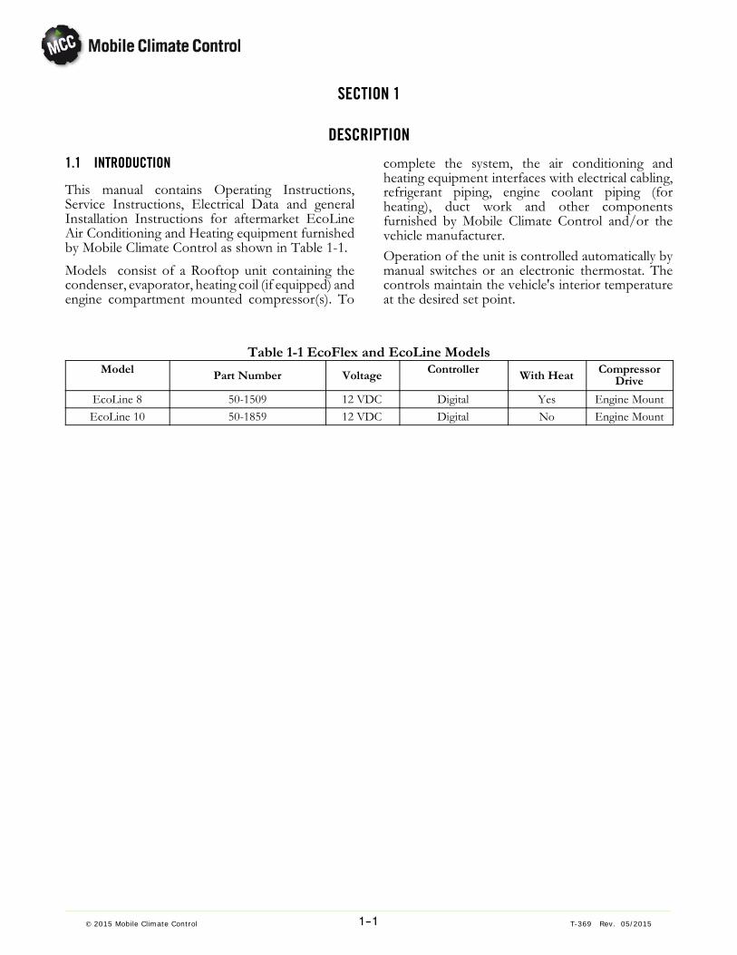
This manual contains Operating Instructions,Service Instructions, Electrical Data and generalInstallation Instructions for aftermarket EcoLineAir Conditioning and Heating equipment furnishedby Mobile Climate Control as shown in Table 1-1.Models consist of a Rooftop unit containing thecondenser, evaporator, heating coil (if equipped) andengine compartment mounted compressor(s). To
complete the system, the air conditioning andheating equipment interfaces with electrical cabling,refrigerant piping, engine coolant piping (forheating), duct work and other componentsfurnished by Mobile Climate Control and/or thevehicle manufacturer.Operation of the unit is controlled automatically bymanual switches or an electronic thermostat. Thecontrols maintain the vehicle's interior temperatureat the desired set point.
Table 1-1 EcoFlex and EcoLine ModelsModel Part Number Voltage Controller With Heat Compressor
Drive
EcoLine 8 50-1509 12 VDC Digital Yes Engine MountEcoLine 10 50-1859 12 VDC Digital No Engine Mount
1--2© 2015 Mobile Climate Control T-369 Rev. 05/2015
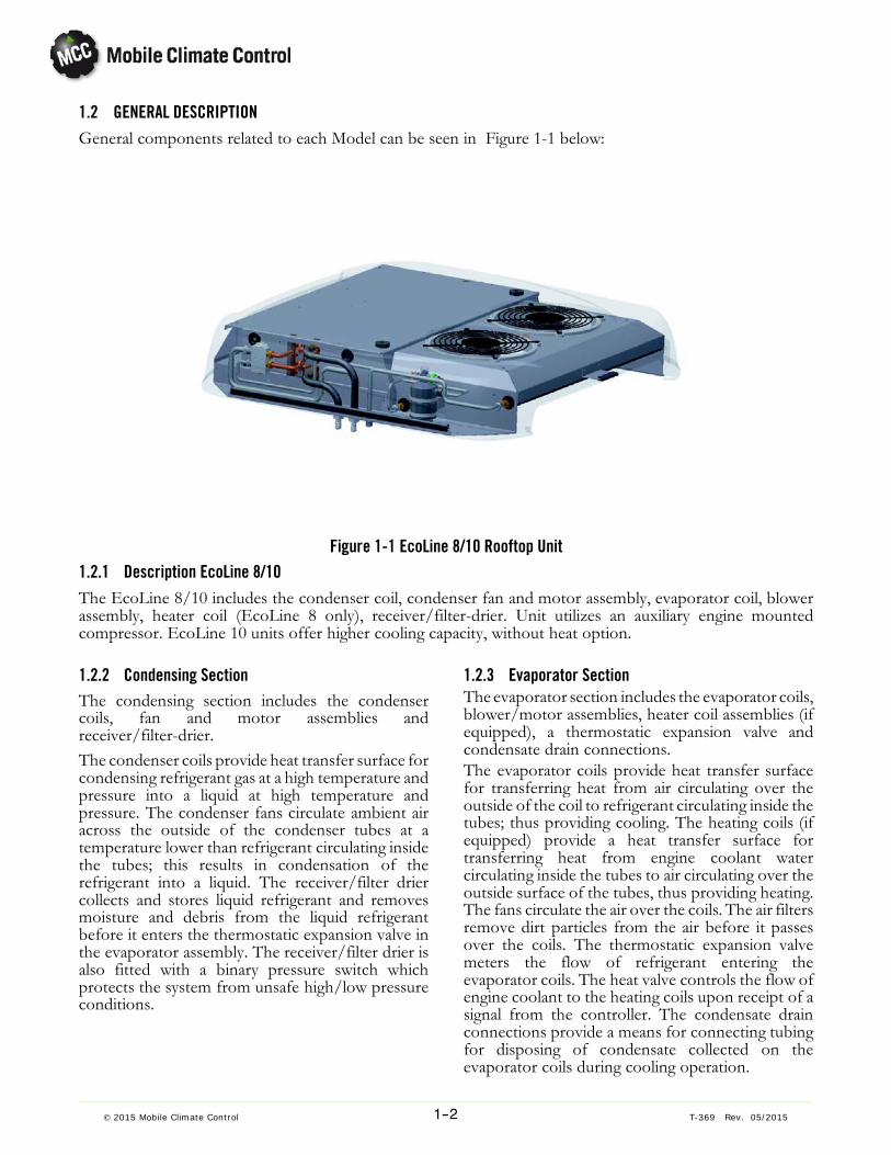
1.2 GENERAL DESCRIPTIONGeneral components related to each Model can be seen in Figure 1-1 below:
Figure 1-1 EcoLine 8/10 Rooftop Unit1.2.1 Description EcoLine 8/10The EcoLine 8/10 includes the condenser coil, condenser fan and motor assembly, evaporator coil, blowerassembly, heater coil (EcoLine 8 only), receiver/filter-drier. Unit utilizes an auxiliary engine mountedcompressor. EcoLine 10 units offer higher cooling capacity, without heat option.
1.2.2 Condensing SectionThe condensing section includes the condensercoils, fan and motor assemblies andreceiver/filter-drier.The condenser coils provide heat transfer surface forcondensing refrigerant gas at a high temperature andpressure into a liquid at high temperature andpressure. The condenser fans circulate ambient airacross the outside of the condenser tubes at atemperature lower than refrigerant circulating insidethe tubes; this results in condensation of therefrigerant into a liquid. The receiver/filter driercollects and stores liquid refrigerant and removesmoisture and debris from the liquid refrigerantbefore it enters the thermostatic expansion valve inthe evaporator assembly. The receiver/filter drier isalso fitted with a binary pressure switch whichprotects the system from unsafe high/low pressureconditions.
1.2.3 Evaporator SectionThe evaporator section includes the evaporator coils,blower/motor assemblies, heater coil assemblies (ifequipped), a thermostatic expansion valve andcondensate drain connections.The evaporator coils provide heat transfer surfacefor transferring heat from air circulating over theoutside of the coil to refrigerant circulating inside thetubes; thus providing cooling. The heating coils (ifequipped) provide a heat transfer surface fortransferring heat from engine coolant watercirculating inside the tubes to air circulating over theoutside surface of the tubes, thus providing heating.The fans circulate the air over the coils. The air filtersremove dirt particles from the air before it passesover the coils. The thermostatic expansion valvemeters the flow of refrigerant entering theevaporator coils. The heat valve controls the flow ofengine coolant to the heating coils upon receipt of asignal from the controller. The condensate drainconnections provide a means for connecting tubingfor disposing of condensate collected on theevaporator coils during cooling operation.

1--3© 2015 Mobile Climate Control T-369 Rev. 05/2015
Table 1-2 EcoLine Model Specifications
EcoLine 8 EcoLine 10
Application Conventional Conventional
Compressor Type Engine Driven Engine Driven
Cooling Capacity
(ARI)
29,000 Btu(8.5 kW)
34,000 Btu(10 kW)
Voltage 12 VDC 12 VDC
Heating Capacity @
Q100 (Air -20°C Water 80°C @
16L/min
34,000 Btu(10 kW)
N/A
Fresh Air No No
Width 43.62” (1108mm) 43.62” (1108mm)
Length 43.74” (1111mm) 43.74” (1111mm)
Height (w/o rails) 7.68” (195mm) 7.68” (195mm)
Air flow (free) 700 CFM (1200 m3/h) 700 CFM (1200 m3/h)
Current (max) 49A (12 VDC) 25A (24 VDC) 60A (12 VDC)
Refrigerant Charge Dependant on application Dependant on application
Weight (total) 100 lbs (45.4 kg) 100 lbs (45.4 kg)
1.3 REFRIGERATION SYSTEM COMPONENT SPECIFI-CATIONS
a. Refrigerant Charge R-134a
NOTERefrigerant charge will depend on hoselengths, diameters and compressor application. Initial charge is 1.5 - 2 lbs. (0.68 -0.91kg). Exact charge adjustment can then be determined by referring to Section 5.6.
b. Thermostatic Expansion Valves:
Superheat Setting Factory Set at 8°F (±1.5°F)
4.57°C (±1°C)
Nominal Capacity 2 Ton
c. Binary Pressure Switch (High/Low)
Opens at: 384±10 psig (26.5±0.69bar)Closes at: 28±10 psig (1.9±0.69bar)
1.4 ELECTRICAL SPECIFICATIONS - Sensors
Output: 10K ± 2% ohms at 77° F (25°C)
1.5 SAFETY DEVICESSystem components are protected from damagecaused by unsafe operating conditions with safetydevices. Safety devices with Mobile Climate Controlsupplied equipment include binary pressure switch(HPS & LPS), circuit breakers and fuses.a. Pressure Switches
High Pressure ConditionDuring the air conditioning cycle, compressor clutchoperation will automatically stop if the HPS switchcontacts open due to an unsafe operating condition.OpeningHPS contacts de-energizes the compressorclutch shutting down the compressor. The highpressure switch is installed in the receiver/filterdrier.Low Pressure ConditionThe low pressure switch is installed in thereceiver/filter drier and opens on a pressure drop toshut down the systemwhen a low pressure conditionoccurs.
b. Fuses and Circuit Breakers
The Relay Board is protected against high current byan OEM or MCC supplied circuit breaker or fuselocated in the power supply circuit to the unit.Independent fuses protect each condenser andevaporator motor. Output circuits are protected by

1--4© 2015 Mobile Climate Control T-369 Rev. 05/2015
additional fuses according to circuit loads. During ahigh current condition, the fuse may open.
1.6 AIR CONDITIONING REFRIGERATION CYCLE
When air conditioning (cooling) is selected , the unitoperates as a vapor compression system usingR-134a as a refrigerant (See Figure 1-2 refrigerantflow diagram). The main components of the systemare the A/C compressor, air-cooled condenser coils,receiver, filter-drier, thermostatic expansion valveand evaporator coils.
The compressor raises the pressure and thetemperature of the refrigerant and forces it into thecondenser tubes. The condenser fan circulatessurrounding air (which is at a temperature lower thanthe refrigerant) over the outside of the condensertubes. Heat transfer is established from therefrigerant (inside the tubes) to the condenser air(flowing over the tubes). The condenser tubes havefins designed to improve the transfer of heat fromthe refrigerant gas to the air; this removal of heatcauses the refrigerant to liquefy, thus liquidrefrigerant leaves the condenser and flows to thereceiver/filter drier.
The refrigerant leaves the receiver/filter drier wherea desiccant keeps the refrigerant clean and dry.
From the filter-drier, the liquid refrigerant then flowsthrough the liquid line to the thermostatic expansionvalve. The thermal expansion valve reduces pressureand temperature of the liquid and meters the flow ofliquid refrigerant to the evaporator to obtain
maximum use of the evaporator heat transfersurface.The low pressure, low temperature liquid that flowsinto the evaporator tubes is colder than the air that iscirculated over the evaporator tubes by theevaporator fans (fans). Heat transfer is establishedfrom the evaporator air (flowing over the tubes) tothe refrigerant (flowing inside the tubes). Theevaporator tubes have aluminum fins to increaseheat transfer from the air to the refrigerant; thereforethe cooler air is circulated to the interior of thevehicle.The transfer of heat from the air to the lowtemperature liquid refrigerant in the evaporatorcauses the liquid to vaporize. This low temperature,low pressure vapor passes through the suction lineand returns to the compressor where the cyclerepeats.
1.7 HEATING CYCLEHeating circuit (See Figure 1-2) componentsfurnished by Mobile Climate Control include theheater cores and electrically operated heat valves andoptional boost water pump.The controller automatically controls the heat valvesduring the heating mode to maintain requiredtemperatures inside the vehicle. Engine coolant(glycol solution) is circulated through the heatingcircuit by the engine and an optional auxiliary boostwater pump. When the heat valve is energized, thevalve will open to allow engine coolant to flowthrough the heater coil.

1--5© 2015 Mobile Climate Control T-369 Rev. 05/2015
Evaporator
Condenser
Heater
TXV (Block)Valve
Receiver/Drier
Compressor(open drive)
High Temperature, High Pressure, Superheated VaporHigh Temperature, High Pressure, Sub-cooled LiquidLow Temperature, Low Pressure, Saturated MixtureLow Temperature, Low Pressure, Superheated VaporEngine Coolant
Air BleedValve
Heat Valve(Optional)
Water Pump(optional)
Binary PressureSwitch
Figure 1-2 Basic Refrigerant/Heat Flow Diagram

2--1© 2015Mobile Climate Control T-369 Rev. 05/2015
SECTION 2
Installation
WARNINGIt is the responsibility of Installer to obtain specific approval from the vehicle manufacturerwith regard to placement andmodification to vehicle roof and body structure. It may be necessary to provide adequate roof structure support to accept the A/C unit to be installed onceOEM approval is obtained. MCC is not responsible for damage related to Installation Issues.
WARNINGBe sure to observewarnings listed in the safety summary in the front of thismanual before performing installation on the hvac system
WARNINGRead the entire procedure before beginningwork. Park the coach on a level surface, with parking brake applied. Turn main electrical disconnect switch to the off position.
NOTETo avoid damage to the earth's ozone layer, use a refrigerant recovery systemwhenever removing refrigerant. When working with refrigerants you must comply with all local government environmental laws.
Table 2-1 STANDARD TORQUE REQUIREMENTS
SIZE TUBE O.D. * FLAREO-RING
THREAD **STEEL TUBING ALUM. TUBING
4 1/4 inch (.250) 11-13 ft./lbs. 30-35 ft./lbs. 5-7 ft./lbs. 7/165 3/8 inch (.375) 15-17 ft./lbs. 30-35 ft./lbs. 8-10 ft./lbs 9/166 3/8 inch (.375) 18-20 ft./lbs. 30-35 ft./lbs. 11-13 ft./lbs 5/88 1/2 inch (.500) 36-39 ft./lbs. 30-35 ft./lbs. 15-20 ft./lbs 3/410 5/8 inch (.625) 52-57 ft./lbs. 30-35 ft./lbs. 21-27 ft./lbs 7/812 3/4 inch (.750) 71-79 ft./lbs. 30-35 ft./lbs. 28-33 ft./lbs 1-1/16
* The tube O.D. is measured at the point it passes through the nut. ** Thread pitch may vary.
2.1 TORQUE SPECIFICATIONS - REFRIGERANT FIT-TINGS
All refrigerant hose fitting connections must betorqued to the specifications listed in Table 2-1.
NOTENomatter what type of lubricant (oil) used inthe system, always usemineral oil to lubricatethe O-Rings and fittings. PAG oils will absorb moisture and become very acidic andcorrosive. Mineral oil absorbs moisture at amuch lower rate than PAG oils.

2--2© 2015 Mobile Climate Control T-369 Rev. 05/2015
2.2 TORQUE SPECIFICATIONS - BOLTS
The torque values listed in Table 2-2 and Table 2-3are are based on the use of lubricated threads.
Table 2-2 Metric Torque Specs
Bolt SizeDia. mm
Torque(Ft-LbCast IronGrade 8.8
Torque(Ft-LbCast IronGrade 10.9
Torque(Ft-LbCast IronGrade 12.9
67810121416
71018305585130
913234575120175
918275095145210
8.8 10.9 12.9
Commercial Grade Head MarkingsMetric Bolts
Grade 8.8 Grade 10.9 Grade 12.9
Figure 2-1 Metric Bolt Markings
Table 2-3 U.S. Torque Specs
Bolt SizeDia. mm
Torque(Ft-Lb)Cast IronGrade 2
Torque(Ft-LbCast IronGrade 5
Torque(Ft-LbCast IronGrade 8
1/4-205/16-183/8-167/16-147/16-201/2-131/2-205/8-115/8-18
51018303245508293
7153045507075135155
112240657095110190215
Commercial Grade Head MarkingsU.S. Customary Bolts
Grade 5 Grade 8Grade 2
Figure 2-2 U.S. Bolt Markings

2--3© 2015Mobile Climate Control T-369 Rev. 05/2015
2.3 Hose installation GuidelinesFlexCLIK - ASSEMBLY INSTRUCTIONS - Continued:
Step 1: Cut the Hose
Cut the hose to proper length with anappropriate cutting tool.Be sure the cut is made square tothe hose length.
Step 2: Slide on Two Clips
Install two proper-sized clips onto the cut end of the hose.Orientation of the clips does not affect the performance of the connection. However, for ease of assembly, both clips should have the same orientation.Note: Failure to slide the clips over the hose at this time will require the clips to be stretched over thehose or fitting later, which may permanently damage the clip.
Step 3: Oil the Nipple
Lubricate the nipple with a generous amount ofmineral oil. This MUST be done to lower theforce of nipple insertion.
CLIPS
FlexCLIK HOSE
SQUARE CUT

2--4© 2015 Mobile Climate Control T-369 Rev. 05/2015
FlexCLIK - ASSEMBLY INSTRUCTIONS - Continued:Step 4: Insert the Nipple into the Hose
To ensure that the nipple is fully inserted, check the gap between the cut end of the hose and theshoulder of the nipple. Care should be taken to avoid kinking or other damage to the hose duringnipple insertion.NOTE: Be sure to wipe excess oil from the nipple and hose
Step 5: Snap on the Cage
Snap the cage into the groove on the nipple. The arms should extend over the hose length. When thecage has been correctly installed in the cage groove, the cage will be able to rotate in the groove. Thisstep MUST be performed to ensure:1. The clips will be located over the O-Rings on the nipple.2. The connection will be compatible with the connection's pressure ratting
Step 6: Slide the Clips
Slide the clips over the cage arms and into the channels on each arm. SEE BELOW
FITTING CLIPSFlexCLIK HOSE
CAGEGROOVE
CHANNELS

2--5© 2015Mobile Climate Control T-369 Rev. 05/2015
FlexCLIK - ASSEMBLY INSTRUCTIONS - Continued:
Step 7: Close the Clips
Use the FlexCLIK pliers to close the clips. The pliers should be positioned squarely on the clip connection points and should remain square during the closing of the clip. SEE BELOW
Nose of the pliers should be firmly seated under the assembly bump and lock latch.If the pliers are not kept square during closing of the clip, the clasp may have an off-set. Usethe pliers to correct the clasp alignment.
Notice: FlexCLIK components should not be reused. For recommendations on cleaning and routing hose assemblies, please consult “Mobile Climate Control Installation Procedures Manual T-311.
2--6© 2015 Mobile Climate Control T-369 Rev. 05/2015
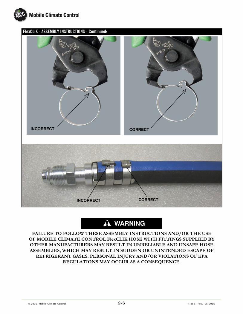
FlexCLIK - ASSEMBLY INSTRUCTIONS - Continued:
INCORRECT CORRECT
INCORRECT CORRECTINCORRECT
WARNINGFAILURE TO FOLLOW THESE ASSEMBLY INSTRUCTIONS AND/OR THE USEOF MOBILE CLIMATE CONTROL FlexCLIK HOSE WITH FITTINGS SUPPLIED BYOTHER MANUFACTURERS MAY RESULT IN UNRELIABLE AND UNSAFE HOSEASSEMBLIES, WHICH MAY RESULT IN SUDDEN OR UNINTENDED ESCAPE OFREFRIGERANT GASES. PERSONAL INJURY AND/OR VIOLATIONS OF EPA
REGULATIONS MAY OCCUR AS A CONSEQUENCE.

2--7© 2015Mobile Climate Control T-369 Rev. 05/2015
2.4 EcoLine 8 & 10 Rail Mounting Method (Sprinter application shown)
Figure 2-3 Overall Layout and Parts Identification

2--8© 2015 Mobile Climate Control T-369 Rev. 05/2015
NOTEThe following procedure is based on an installation on a Mercedes Sprinter with a Freightliner chassis.General routing of hoses and electrical interface will differ on other vehicles, however general guidelinesshould be followed.
NOTETheEcoLine railmounted roof units are designed to utilizeOEM/Installer provided roof rails to securethe unit to vehicle.
NOTEPlacement of the EcoLine rail mounted roof units should straddle the supply and return roof openingson either side of a roof bow support without altering the roof bow support.
NOTEBefore beginning the instructions listed below, it will be necessary to remove the interior headliner inthe areas surrounding hose/electrical routing and area the unit is to be installed.
2.4.1 Roof Cut Out and Transition Duct Mounting
1. Based on the intended use of vehicle, determinethe best location for placement of A/C unit.
2. It is beneficial to identify roof support bow locations.Onemethod is to used the bolts securing theOEM rails as a reference dimension for roof bow(see figure Figure 2-4 and Figure 2-5 ).
OEM RailMounting Bolt
Figure 2-4 Determining Roof Support Bow Location
OEM RailMountingBolt
Figure 2-5 Marking of Roof Support Bows3. Temporarily mark lines referencing the roof support bow to assist in template orientation. Onemethod is using a chalk line that can be easily removed (see figure Figure 2-6).

2--9© 2015Mobile Climate Control T-369 Rev. 05/2015
Chalk Lines ofRoof SupportBow location
Figure 2-6 Template Orientation
4. Using dimensions in Figure 2-10, construct atemplate using a rigid material to assist in layout ofsupply and return location cut outs.
NOTE:To assist with install a metal template isavailable for purchase if desired, part #Y24-00370.
Figure 2-7 Determining Location for Unit
5. Mark off roof cut outs for the supply and returnopenings straddling each side of roof support bow(see Figure 2-8).
Figure 2-8 Marking Roof Cut-Outs
NOTEOnce location for cut-outs are determined, itmay be beneficial to apply masking tape atopening locations to mark the cut-outs andhelp protect roof surface while cutting.
6. Drill ¼” pilot holes in the 4 corners of both openings for supply and return air distribution. Remember to drill pilot holes ½“ in from eachside because holes will be enlarged with a 1”hole saw. Refer to Figure 2-9.
7.Once pilot holes have been drilled, check for proper clearance on interior of vehicle before proceeding.
8. Using a 1” hole saw, drill out the corners of eachsupply and return opening.
9. Use a jig/scroll saw to complete the cut out of roofopenings for supply and return access. SeeFigure 2-9.
Figure 2-9 Supply and Return Cut Outs

2--10© 2015 Mobile Climate Control T-369 Rev. 05/2015
REF: Y66-14084
Figure 2-10 EcoLine 8 and 10 Mounting Template

2--11© 2015Mobile Climate Control T-369 Rev. 05/2015
10. Once cut outs have been made, de-burr the exposed metal surfaces that were cut (SeeFigure 2-11).
Figure 2-11 De-Burr cut edges
11. Thoroughly clean the roof of all metal shavingsand dirt. Paint all exposed/bare metal with primerpaint, both inside and outside of areas cut.
NOTEBe sure to tape off all areas of roof to avoidany over spray onto existing painted surfaces.
NOTEFigure 2-12 Shows a basic layout of howtransition ducts 24-12088 (outlet/supply air)and 24-12086 (inlet/return air) will interfaceinto the openings provided in the base ofunit.
NOTEThe return air transition duct is taller on oneside. The taller side should be positioned tothe rear of vehicle. See Figure 2-12.
Mounting Rail
Roof Surface
Interior Headliner
Air Distribution Assembly
Supply AirTransition Duct
Return AirTransition Duct
NOTE:The return air transition duct is talleron one side. The taller side should bepositioned to the rear of vehicle.
Air DistributionBracket
Figure 2-12 General Assembly Layout of Rail Mounted Unit
2--12© 2015 Mobile Climate Control T-369 Rev. 05/2015
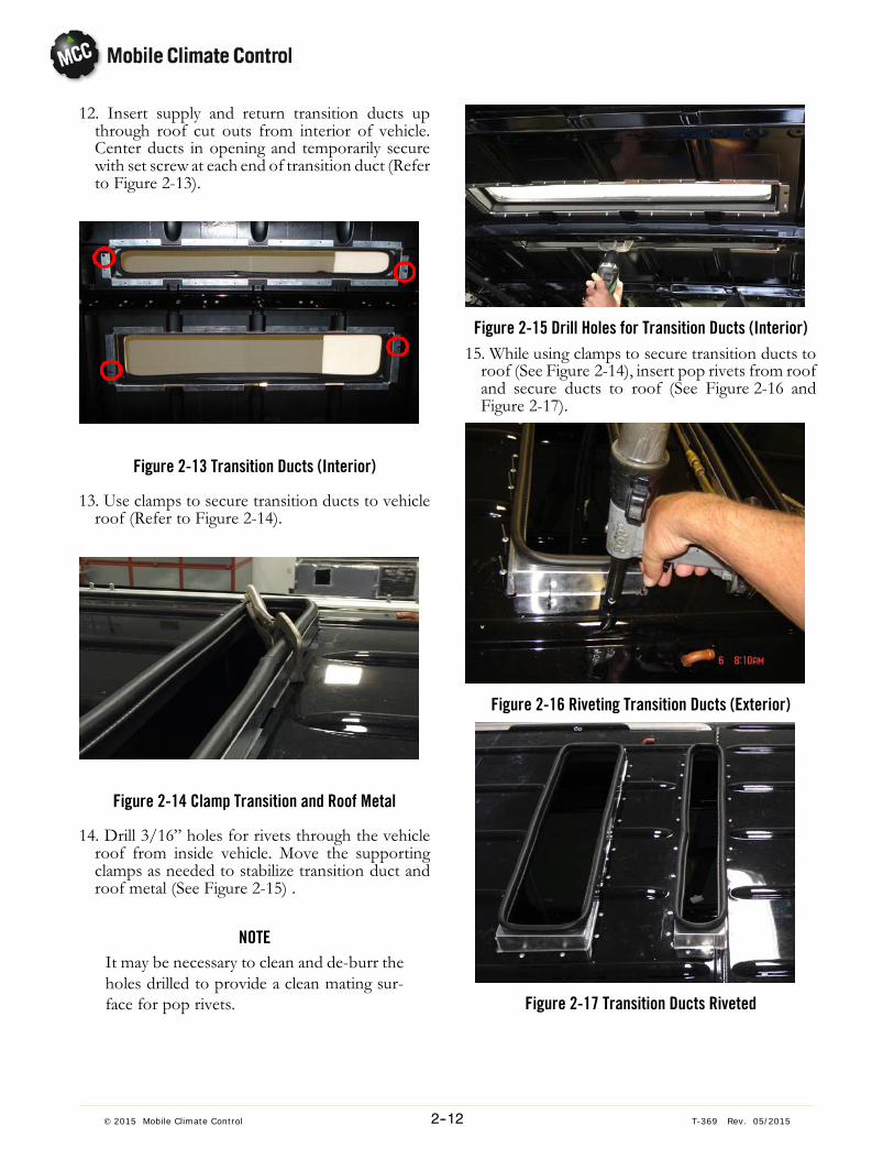
12. Insert supply and return transition ducts upthrough roof cut outs from interior of vehicle.Center ducts in opening and temporarily securewith set screw at each end of transition duct (Referto Figure 2-13).
Figure 2-13 Transition Ducts (Interior)
13. Use clamps to secure transition ducts to vehicleroof (Refer to Figure 2-14).
Figure 2-14 Clamp Transition and Roof Metal
14. Drill 3/16” holes for rivets through the vehicleroof from inside vehicle. Move the supportingclamps as needed to stabilize transition duct androof metal (See Figure 2-15) .
NOTEIt may be necessary to clean and de-burr theholes drilled to provide a clean mating surface for pop rivets.
Figure 2-15 Drill Holes for Transition Ducts (Interior)15. While using clamps to secure transition ducts toroof (See Figure 2-14), insert pop rivets from roofand secure ducts to roof (See Figure 2-16 andFigure 2-17).
Figure 2-16 Riveting Transition Ducts (Exterior)
Figure 2-17 Transition Ducts Riveted

2--13© 2015Mobile Climate Control T-369 Rev. 05/2015
16. In preparation for sealing around transitionducts, it may be beneficial to applymasking tape orsimilar product to prevent sealant from enteringthe interior of vehicle (Refer to Figure 2-18).
Figure 2-18 Preparation of Sikaflex application
17. Clean roof surface around transition ducts andadequately seal roof cut out seams and rivets attransition ducts to prevent external water leaks.(Refer to Figure 2-27).
Figure 2-19 Transition and Rivets Sealed

2--14© 2015 Mobile Climate Control T-369 Rev. 05/2015
2.4.2 Air Distribution and Interior Roof Support
1. Mount supplied Air Distribution Brackets as seen in Figure 2-20.
Front
Rear Y24-00367-03
Y24-00367-01
Y24-00367-00
Y24-00367-02
Y24-00369-00(3 PLCS)
801-403(4 PLCS)
Figure 2-20 Air Distribution Bracket
2. The vertically mounted brackets provided will utilize existing holes in roof support bows by inserting8 Tinnerman clips (part# 701-123) and 6 RivNuts(part number 34-06051-104). See Figure 2-3 forlocations.
Slotted Holes forHose/HarnessRouting
Front
Rear
Figure 2-21 Orientation of Slotted Holes
Figure 2-22 Nut Inserts

2--15© 2015Mobile Climate Control T-369 Rev. 05/2015
Figure 2-23 Vertical Bracket Installation
Figure 2-24 Horizontal Bracket Installation
NOTEThe slotted cut outs in vertical run channelswill be used for routing refrigerant lines onthe curbside, and the electrical and heaterlines on the roadside (See Figure 2-25 andFigure 2-26).
Figure 2-25 A/C Hose Routing Curbside
Figure 2-26 Electrical Harness Routing Roadside

2--16© 2015 Mobile Climate Control T-369 Rev. 05/2015
2.4.3 Roof Unit Installation
Once the Sikaflex sealant has set, the placement ofthe Eco 8 or 10 roof unit can be performed.1. Position the 8 rail mounting bolts supplied in Kit,part # Y29-00045-00 for securing unit to the roofrails. See Figure 2-27.
Figure 2-27 Mounting Rail Hardware
2. Using a lift or hoist, carefully position the roof unitover the transition ducts and rail mounting bolts.(See Figure 2-28 thru Figure 2-29).
Figure 2-28 Hoist for Unit
Figure 2-29 Setting unit
3. Lower unit slowly, taking care that drain lines orother items clear the transition ducts and bulb gaskets are not damaged. (See Figure 2-30).
Figure 2-30 Lowering onto Transition Ducts4. Once unit has been properly positioned and set,secured unit mounting rails to the OEM roof railswith washers and nuts provided (See Figure 2-31).
Figure 2-31 Unit Set and Secured

2--17© 2015Mobile Climate Control T-369 Rev. 05/2015
2.4.4 Refrigerant Hose Routing
Refrigerant hose routing on the Mercedes Sprinter application will be done on the passenger side of vehicle asshown in Figure 2-32.
Figure 2-32 A/C Hose Routing Curbside
1. If installation is being performed on a finished interior vehicle, it will first be necessary to removethe interior panels and headliners.
2. Remove cover from “B” column behind the frontpassenger seat as seen in Figure 2-33.
Block OffPanel
Figure 2-33 Passenger column “B” cover3. There is a plastic block off plate in the column thatwill need access holes be drilled in order to routehoses (See Figure 2-33).
4. To gain access into the column, remove the Styrofoam plug located under vehicle directly under thecolumn (See Figure 2-34).
Figure 2-34 Styrofoam Access Cover5. The column block off plate can be seen inFigure 2-35. Holes will need to be drilled for hoserouting. A hole saw with extension as seen inFigure 2-36 can be used.

2--18© 2015 Mobile Climate Control T-369 Rev. 05/2015
Access Holes required for hose routing
Figure 2-35 Column Block Off Plate
Figure 2-36 Hole Saw with Extension6. Once access holes have been cut, the refrigeranthoses can be routed up from underneath thevehicle, through the block off plate. Dependingonchassis, either feed hoses to the access hole at thetop of column (See Figure 2-37), or exit at the holeby seat belt (See Figure 2-38).
NOTEIf chassis requires the hoses to exit column atthe seat belt access hole, care needs to betaken to eliminate the possibility of obstructing seat belt operation or chafing of the refrigerant lines.
NOTEThe suction hose should be insulated to prevent possibility of line “sweating” duringperiods of high humidity and high interiortemperatures.
Figure 2-37 Passenger column “B” Top Access
Figure 2-38 Passenger column “B” Seat belt Access7. Route refrigerant lines up to top of column asshown in Figure 2-39. Continue pulling enoughhose to reach the unit connections before securing.
NOTEAll areas where hoses could come in contactor rub on sharp edges should be protectedusing trimlok or other protective material.
NOTEBe certain to leave enough hose beneathvehicle to route refrigerant hoses to the engine mounted compressor.

2--19© 2015Mobile Climate Control T-369 Rev. 05/2015
Figure 2-39 Upper Passenger Column Hose Routing
8. Route refrigerant lines up to top of column asshown in Figure 2-39. Continue pulling enoughhose to reach the unit connections before securing.
NOTEProtective rubber P-clamps should be usedto secure hoses to roof support bows, utilizing existing holes at corners. Screws andproper Tinnerman clips will work nicely.
9. Secure refrigerant lines in place (See Figure 2-40) .
Figure 2-40 Passenger side Hose Routing to Unit
10. Install refrigerant fittings and interface refrigerantlines to the unit (See Figure 2-41). Section 2.3provides instructions for proper fitting/hose installation procedures. Torque fittings according tovalues in Table 2-1.
Figure 2-41 Refrigerant Hose Routing at Unit
11. Route lines from base of passenger column to engine compartment.
NOTEWheel well covers at front passenger side tirewill need to be removed in order to properlysecure and protect refrigerant hose routingin this area.
12. Route lines from base of passenger column to engine compartment.
Figure 2-42 Refrigerant Hose Under Vehicle

2--20© 2015 Mobile Climate Control T-369 Rev. 05/2015
13. Service access ports could be cut in betweencolumn access plug under vehicle and where thehoses go behind wheel well covers. This provideseasy access for servicing (See Figure 2-43).
Figure 2-43 Service Port Fittings14. Route refrigerant hoses through front passengerside wheel well (See Figure 2-45 and Figure 2-44).
NOTEProtective sleeve should be added over hosesleaving compressor and into wheel well area.
Figure 2-44 Wheel Well Routing
Figure 2-45 Wheel Well Routing
15. There will be areas where trimlok or protectivematerial will be required to avoid hose chafing (SeeFigure 2-46 and Figure 2-47).
Figure 2-46 Hose Protection (Brake Line Bracket)

2--21© 2015Mobile Climate Control T-369 Rev. 05/2015
Figure 2-47 Hose Protection (Vehicle Frame)
16. Route refrigerant lines from wheel well to compressor. Be sure to leave extra hose to provide aservice loop and slack for engine movement underthrottle conditions
Figure 2-48 Hose Routing to Compressor
17. Add additional sleeve material to hose if necessary and install compressor fittings.
Figure 2-49 Hose Routing to Compressor with “Sleeve”18. Secure fittings onto compressor. Torque fittingsaccording to values in Table 2-1.
Figure 2-50 Fittings at Compressor19. Verify hoses are properly secured and protectedat all routing points.
NOTEDONOT re-install the wheel well coversuntil the wiring for compressor clutchhas been installed.

2--22© 2015 Mobile Climate Control T-369 Rev. 05/2015
2.4.5 Electrical Harness RoutingElectrical harness routing on theMercedes Sprinter application will be done on the driver side of vehicle, fromdriver seat pedestal to A/C unit as shown in Figure 2-51.
Figure 2-51 Electrical Harness Routing Roadside
1. A good starting pointmay be to begin by layingoutmain control harnesswhich goes fromA/C unit todriver pedestal and driver display.
2. Position the control harnesswhere it splits to go tothe driver display and drop down to the driver pedestal at the top of column “A” behind driver seat(See Figure 2-52).
Harness todriver display
Harness todriver pedestal
Harness to A/CUnit
HarnessSplits
Main Power (4 ga. Wire)to A/C Unit
Figure 2-52 Electrical Harness Positioning

2--23© 2015Mobile Climate Control T-369 Rev. 05/2015
3. Secure the harness at top of column.4. Route the main power wire (4 Ga.) down thecolumn along with the control harness. Leave adequate length to continue routing into driver pedestal and connect to the load side of electrical contactor.
5. Depending on chassis, route the main power wire(4Ga.) and control harness into the drivers pedestal. A possible option is an opening of pedestal onside facing driver's door (See Figure 2-53).
NOTEIt may be necessary to loosen bolts of driverpedestal to route wires. Be sure that wires donot get crushed or pinched. If the routingcannot be completed safely, consider alternative path.
Figure 2-53 Electrical Routing from Column Base toPedestal
6. Route the control harness from top of drivercolumn, above driver door and across front windshield to center of vehicle where display will bemounted in front headliner (See ).
Display Harness
Figure 2-54 Electrical Routing from Column to DriverDisplay
Figure 2-55 Driver Display Mounted7. Continue routing the control harness from top ofdriver column along the driver's side ceiling to theA/C unit. Use rubber protective P-clamps or wiretie to existing electrical harness fasteners to secure.Harness wires may need to be routed behind aStyrofoam brace for headliner (see Figure 2-56).

2--24© 2015 Mobile Climate Control T-369 Rev. 05/2015
Figure 2-56 Electrical Routing from Column to A/C Unit8. Route power harness and control harness throughslotted hole in air distribution framing and connect to appropriate power stud and connectors(See Figure 2-57 and Figure 2-58).
Main Power
Control Harness Connections
Figure 2-57 Electrical Routing Inside A/C Unit
OEM Ground Stud
Figure 2-58 Electrical Routing into A/C Unit
9. Route the main ground harness supplied in kitfrom ground stud in unit return air section to theOEM stud at rear driver's side corner of vehicle(See Figure 2-58).
10.Neatly route and secure the electrical harnesses atA/C unit.
11. Using harness supplied in the install kit (Part#Y25-00090-54), route 4Ga. wire from battery postmanifold to the inside of driver's pedestal (SeeFigure 2-59). It may be necessary to un-bolt pedestal to feed wiring into pedestal.
NOTEIt may be necessary to loosen bolts of driverpedestal to route wires. Be sure that wires donot get crushed or pinched. If the routingcannot be completed safely, consider alternative path.
Figure 2-59 Electrical Routing From Vehicle Battery

2--25© 2015Mobile Climate Control T-369 Rev. 05/2015
12. Mount electrical panel (Part# Y25-00090-00) inside of driver pedestal. Panel may be different forthe Eco 8 (with heat) which utilizes and extra relayfor boost pump option, as opposed to the Eco 10unit without heat option (See Figure 2-60 thruFigure 2-62) . The panel may require holes to bedrilled (Figure 2-62), ormounted to exist studs depending on vehicle chassis (Figure 2-60).
NOTEBe sure to properly route and protect all wiring from chafing against sharp surfaces.
Figure 2-60 Eco 10 Panel Installed
Figure 2-61 Eco 8 Panel Components
Figure 2-62 Eco 8 Panel Installed13. Following the electrical schematic for Section ofmanual, connect electrical harnesses to contactorsand relay (If applicable). Supplied harnesses arelabeled with point A to point B labels. OEM ignition interface should be done at EK1 terminal asper OEM instructions (See Figure 2-63).
NOTEBe sure to identify the correct terminal/studdesignated EK1, as orientation of stud mayvary depending on chassis.
EK1 Location
Figure 2-63 OEM Interface

2--26© 2015 Mobile Climate Control T-369 Rev. 05/2015
14. A wire included in the electrical harness insidedriver pedestal will need to be routed to the compressor clutch . There is a “boot” located throughflooring at pedestal that can be used to route thecompressor signal wire supplied in harness (seeFigure 2-64 and Figure 2-65).
Clutch Signal Wire
Figure 2-64 Electrical Boot from Driver Pedestal
Clutch Signal Wire
Figure 2-65 Electrical Boot Under Driver Pedestal
15. The clutch signal wire will need routed fromdrivers side of vehicle, to the passenger side. Anexample of routing is shown in.
Clutch Signal Wire
Figure 2-66 Clutch Signal Wire Routing Under Vehicle16. Continue routing the clutch signal wire upthrough the front passenger wheel well along thesame path as refrigerant hoses in Section 2.4.4.
Clutch Signal Wire
Figure 2-67 Clutch Signal Wire at Wheel Well
2--27© 2015Mobile Climate Control T-369 Rev. 05/2015
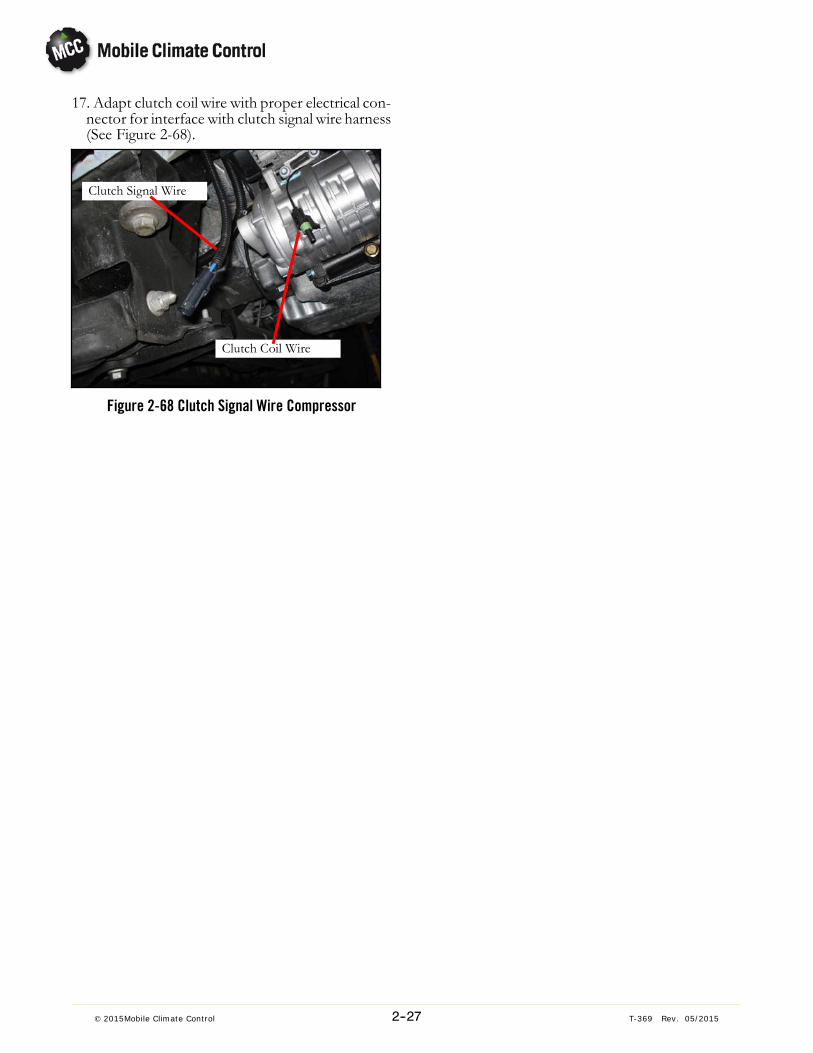
17. Adapt clutch coil wire with proper electrical connector for interface with clutch signal wire harness(See Figure 2-68).
Clutch Signal Wire
Clutch Coil Wire
Figure 2-68 Clutch Signal Wire Compressor

2--28© 2015 Mobile Climate Control T-369 Rev. 05/2015
2.4.6 Heater Hose Routing (Eco 8 Only)Heater hose routing on theMercedes Sprinter application will need to be determined. If decided to be done onthe interior of driver side of vehicle, from column “A”behind driver seat to A/C unit, refer to Figure 2-70. If itis determined to run heater hoses on the exterior of vehicle, the hoses will require insulation to be added.
Figure 2-69 General Overview of Heater Hose Routing
Figure 2-70 Optional Heater Hose Routing Roadside (Interior)

2--29© 2015Mobile Climate Control T-369 Rev. 05/2015
1. Begin by removing protective metal cover underneath the vehicle, over fuel fill tube. Cover is located directly underneath driver column “A” (SeeFigure 2-71).
Figure 2-71 Protective Metal Fuel Fill Cover2. Once cover is removed, drill 2 holes large enoughto accept the heater hoses through the Styrofoamplug that is covering the column opening (SeeFigure 2-72).
CAUTIONThere may be sensor wiring above the Styrofoam plug. Be careful not to damage this wiring.
Figure 2-72 Plug Holes at Driver Column UnderneathVehicle
3. In order to provide easier access in routing thelines from under vehicle to top of driver column,remove the Fuel fill door and cap shown inFigure 2-73.
Figure 2-73 Fuel Fill Access Door4. To prevent chafing, install protective sleeve atareas where heater lines come in contact withsharp edges. Example can be seen in Figure 2-74.

2--30© 2015 Mobile Climate Control T-369 Rev. 05/2015
Figure 2-74 Heater Hose Protection
5. Heater lines will exit driver column as seen inFigure 2-75. Trimlok or protectivematerial shouldalso be used at opening to protect heater lines.
Figure 2-75 Heater Hose Exiting Column
6. Heater lines will be run along top corner of driveside, along with electric harnesses. If there is anyStyrofoam “stand-offs”, they will require modifications to route lines behind them, to avoid interference with headliners when re-installed.
NOTEFigure 2-76 Does not show the air distribution bracket. The lines will be run throughslotted opening in air distribution bracket,along with electrical harnesses, similar to refrigerant lines seen in Figure 2-41.
Figure 2-76 Heater Hose Routing Along Roadside7. Rubberized protective P-clamps should be used tosecure heater hoses using existing holes in roofbows. Proper size Tinnerman clips and screws willaccomplish this.
8. If an auxiliary boost pump is to be used in the application, it can be installed under vehicle whereheater lines exit the driver column.
Figure 2-77 Auxiliary Boost Pump
2--31© 2015Mobile Climate Control T-369 Rev. 05/2015
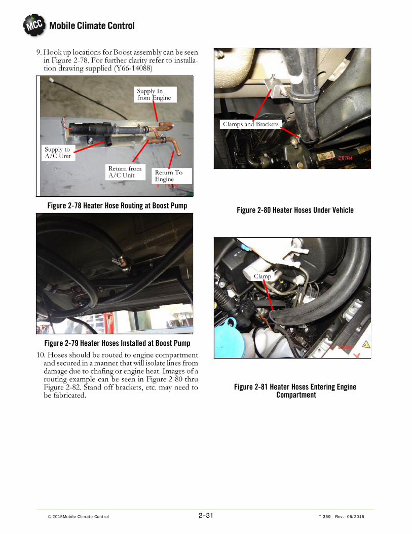
9. Hook up locations for Boost assembly can be seenin Figure 2-78. For further clarity refer to installation drawing supplied (Y66-14088)
Supply Infrom Engine
Supply toA/C Unit
Return fromA/C Unit Return To
Engine
Figure 2-78 Heater Hose Routing at Boost Pump
Figure 2-79 Heater Hoses Installed at Boost Pump10. Hoses should be routed to engine compartmentand secured in amanner that will isolate lines fromdamage due to chafing or engine heat. Images of arouting example can be seen in Figure 2-80 thruFigure 2-82. Stand off brackets, etc. may need tobe fabricated.
Clamps and Brackets
Figure 2-80 Heater Hoses Under Vehicle
Clamp
Figure 2-81 Heater Hoses Entering EngineCompartment

2--32© 2015 Mobile Climate Control T-369 Rev. 05/2015
Figure 2-82 Heater Hose Routing in Engine Compart-ment
Clamps and Brackets
Figure 2-83 Heater Hose Routing at Air CleanerBracket
11. Once hoses have been routed into engine compartment, interfacing with the OEM system at In-dash heater coil can be done with the “Y” fittings
provided.Detail of supply and return interface canbe seen in Figure 2-84.
SupplyReturn
Figure 2-84 Heater Hose Interface12. To aide with bleeding air from heater system, ableed valve has been provided on the heater coil asseen in.
BleedScrew
Figure 2-85 Heater Hose Interface

2--33© 2015Mobile Climate Control T-369 Rev. 05/2015
2.4.7 Condensate Line RoutingA general layout of condensate drain line routing can be seen in Figure 2-86.
NOTEIt ismandatory that the front and rear drain lines remain separated. Differences in air pressures acrosscoil will hinder the ability of the condensate to drain properly if the front and rear drain lines are tiedtogether. Condensate hoses should be carefully routed to provide a downhill slope through entire routing process. The side to side routing of hoses is ultimately decided according to application, so long asthe front of pan is routed to one side, and the rear is routed to the opposite side to provide properdrainage.
Figure 2-86 General Routing of Condensate Lines
1. Elbows, T-fittings, clamps and hose are providedin the installation kit to perform the following outlined procedures.
Figure 2-87 Route Condensate Lines for Proper Slope
2. It is important when routing drain lines to providea consistent downward slope between drain linefittings. Example can be seen in Figure 2-87.
The elbow fitting shouldbe positioned as close tothe drain pan nipple aspossible to allow for re-quired slope.
The “T” fitting should bepositioned with a slightlylonger section of hose toprovide the side to sideslope between drain pannipples as shown inFigure 2-87.
Figure 2-88 Drain Pan Connections

2--34© 2015 Mobile Climate Control T-369 Rev. 05/2015
3. Once condensate hose is routed from drain panconnections to exterior sidewalls, a consistentdownward slope should be continued to the pointof entry into the rear column of vehicle as shownin Figure 2-89.
Figure 2-89 Sidewall Routing of Condensate Lines
4. Holes will need to be drilled in body underneaththe vehicle for the condensate drain lines to exitthe rear columns on both the road side and curbside of vehicle. The location for these holes isshown in Figure 2-90.
NOTEAlways be sure to prime any exposed metalwhen cutting or drilling into vehicle body
Hole location
Figure 2-90 Exit Hole Location for Condensate Lines5. Once the condensate hose has been “fished”down through the exit hole, the hose should betrimmed to length and the kazoo valve should beconnected as shown in
Figure 2-91 Kazoo Valve Installation

3--1© 2015 Mobile Climate Control T-369 Rev. 05/2015
SECTION 3
OPERATION of the MVC DIGITAL CONTROLLER
3.1 STARTING, STOPPING AND OPERATING INSTRUC-TIONS
The MVC Digital Display is marked withinternational symbols (See Figure 3-1).
Before starting, electrical power must be availablefrom the bus power supply.
3.1.1 Startinga. If the engine is not running, start the engine.b.When the 12VDC power is applied, the driver display will illuminate and show return air set point. Ifdisplay does not illuminate, press the On/Off key( Item 1 in Figure 3-1).
3.1.2 StoppingToggling the On/Off button (Item 1 Figure 3-1) onthe display again will stop the system operation.
1
234
5
6
Figure 3-1 MVC Controller
1. On/Off Button2. LCD Display3. Set/Select Knob
4. Temperature Set Point5. Mode of Operation6. Blower Speed
NOTE:The following procedures are general in nature and are dependant on the software version installed inthe MVC Controller module and system related components and sensors.

3--2© 2015 Mobile Climate Control T-369 Rev. 05/2015
3.2 OPERATING INSTRUCTIONS
When the engine is running, toggle the A/C Switchto “ON” to activate the Air Conditioning Unit.
Figure 3-2 MVC Main Screen
3.2.1 Display
When the unit is initially turned ON, the displayshows the interior set point temperature, controlmode and blower speed. After a few seconds, thedisplay will show the interior air temperature. Whenselecting individual functions, the display shows thecorresponding information.The display is darkwhenthe engine and control unit are OFF.3.2.2 Interior Temperature Control
To adjust the desired interior set point, turn the “Set”knob one click in either direction and the display willshow screen as seen in Figure 3-2. Simply turn the“Set” knob counter clockwise to lower temperatureor clockwise to increase temperature set pointThe temperature can be adjusted between 62° F (17°C) and 82° F (28° C).
NOTE:
When the outside temperatures are below 45° F (7°C) (adjustable parameter), the A/C compressorremains disabled until temperature rises above 50°F(10°C).3.2.3 Blower Speeds
Figure 3-3 MVC Blower Speeds
When the unit is operating in Automatic ClimateControl mode, the blower speed is controlled basedon the interior temperature.Tomanually select the blower speed operation, pressthe “Set” knob while the main screen (Figure 3-2) isshowing, until display shows the “Fan” symbol asseen in Figure 3-3. Rotate the “Set” knob to desiredfan speed.
NOTE:
If the blowers are switched to OFF when in the“AUTO” mode, the A/C compressor willde-energize.If the blowers are switched to OFF when in the“HEAT” mode, the heater control valve willde-energize.
3.2.4 Modes of OperationTo manually select the operation mode, press the“Set” knob while the main screen (Figure 3-2) isshowing, until display shows the “MODE” symbolas seen in Figure 3-3. Rotate the “Set” knob todesired mode. Decscription of mode operations islisted below.
Figure 3-4 MVC Modes
The AUTO mode controls interior temperaturebased on selected set point. The controllerconstantly monitors the system electronic sensorsand controls A/C and heat functions (if equipped)accordingly.
The HEATmode operates electronic heater valve (ifequipped) based on selected set point. The A/Ccompressor circuit is de-energized while in heatmode. When set point temperature is reached,evaporator fans continue to circulate interior air.

3--3© 2015 Mobile Climate Control T-369 Rev. 05/2015
The COOLmode cycles the A/C compressor basedon selected set point. The A/C compressor circuit isde-energized when set point temperature is reached,evaporator fans continue to circulate interior air.
NOTE:
When the outside temperatures are below 45° F (7°C) (adjustable parameter), the A/C compressorremains disabled until temperature rises above 50°F(10°C).
3.3 CHANGING BETWEEN °F (FAHRENHEIT) AND °C(CELCIUS )
Procedures for changing the MVC Controllerbetween Fahrenheit and Celsius is as follows:To toggle between Fahrenheit and Celsius, press the“Set” knob while the main screen (Figure 3-2) isshowing, until display shows the “MODE” symbolas seen in Figure 3-3.Press and hold the On/Off button (Item 1 inFigure 3-1) while rotating the “Set” knob 3 clickscounterclockwise.Press the “Set” knob to highlight temperaturedesignation (see Figure 3-5 ) and turn the “Set” knobto change.Press “Set” knob to exit
Figure 3-5 °F to °C
3.4 MVC DIAGNOSTICS MENU
To enter the diagnosticsmenus, press the “Set” knobwhile the main screen (Figure 3-2) is showing, untildisplay shows the “MODE” symbol as seen inFigure 3-3.Press and hold the On/Off button (Item 1 inFigure 3-1) while rotating the “Set” knob 3 clicksclockwise.By turning the “Set” knob, user can toggle betweenthe Setup, View, Statistics and Error List menus.
3.4.1 Setup Menu
Figure 3-6 Setup Menu
In the “Set Up”menu, the only parameter that can bemodified is the date. The parameter for installedsoftware is dependant on current software installed.To modify date, press the “Set” knob once, and themonth can be modified by turning the “Set” knob ineither direction.When finished, press the “Set” knobagain once, and the day can be modified by turningthe “Set” knob. Press the “Set” knob again one timeand the Year can be modified by turning the “Set”knob.When complete, press the “Set” knob to complete.3.4.2 View Menus
In the “VIEW” menus, the controller's input andoutput parameters will be shown. This may includeall temperature sensors, system status settings anddisplay settings. Any errors from sensors, pressureswitches, heater valve or A/C system fail can beobserved.
Figure 3-7 View Menus
3--4© 2015 Mobile Climate Control T-369 Rev. 05/2015
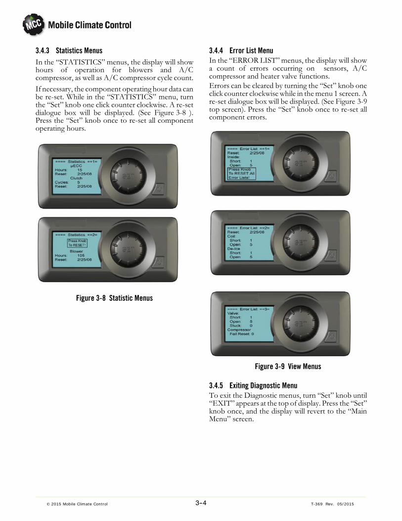
3.4.3 Statistics MenusIn the “STATISTICS” menus, the display will showhours of operation for blowers and A/Ccompressor, as well as A/C compressor cycle count.If necessary, the component operating hour data canbe re-set. While in the “STATISTICS” menu, turnthe “Set” knob one click counter clockwise. A re-setdialogue box will be displayed. (See Figure 3-8 ).Press the “Set” knob once to re-set all componentoperating hours.
Figure 3-8 Statistic Menus
3.4.4 Error List MenuIn the “ERROR LIST” menus, the display will showa count of errors occurring on sensors, A/Ccompressor and heater valve functions.Errors can be cleared by turning the “Set” knob oneclick counter clockwise while in themenu 1 screen. Are-set dialogue box will be displayed. (See Figure 3-9top screen). Press the “Set” knob once to re-set allcomponent errors.
Figure 3-9 View Menus
3.4.5 Exiting Diagnostic MenuTo exit the Diagnostic menus, turn “Set” knob until“EXIT” appears at the top of display. Press the “Set”knob once, and the display will revert to the “MainMenu” screen.

4--1© 2015 Mobile Climate Control T-369 Rev. 05/2015
SECTION 4
TROUBLESHOOTING
Table 4-1 General System Troubleshooting Procedures
INDICATION/TROUBLE POSSIBLE CAUSES
4.1 SYSTEM WILL NOT COOLCompressor will not run Drive--Belt loose or defective
Clutch coil defectiveClutch malfunctionLow refrigerant chargeCompressor malfunction
Electrical Malfunction Circuit Breaker OpenRelay Defective
4.2 SYSTEM RUNS BUT HAS INSUFFICIENT COOLINGCompressor Drive--Belt loose or defective
Compressor defective
Refrigeration system Abnormal pressuresNo or restricted evaporator air flowExpansion valve malfunctionRestricted refrigerant flowLow refrigerant charge
4.3 ABNORMAL PRESSURESHigh discharge pressure Refrigerant overcharge
Non--condensables in systemCondenser motor(s) failureDirty Condenser coil
Low discharge pressure Compressor defectiveLow refrigerant charge
High suction pressure Compressor defectiveLow suction pressure Filter---drier or Receiver---Drier partially plugged
Low refrigerant chargeExpansion valve malfunctionRestricted air flow
Suction and discharge pressuresequal or near equal
Compressor valves defective

4--2© 2015 Mobile Climate Control T-369 Rev. 05/2015
4.4 ABNORMAL NOISES, VIBRATIONS OR CONDITIONSCompressor -- Engine area Compressor or compressor mounting loose
Liquid sluggingInsufficient oilExcessive oilClutch loose, rubbing or defectiveDirt or debris on vehicle fan bladesDrive belt cracked, worn or loose
Evaporator area Evaporator blower assembly broken or looseBlower wheel loose or out of alignmentBlade interference
Condenser area Broken or missing fan bladeCondenser assembly looseFan assembly loose
4.5 NO EVAPORATOR AIR FLOW OR RESTRICTED AIR FLOWAir flow through coil blocked Coil frosted over
Dirty coilDirty filter assembly
No or partial evaporator air flow Motor running in reverseMotor(s) defectiveEvaporator fan loose or defectiveFan damagedDirty filterIcing of coilFan speed control defectiveFan rotation incorrect
4.6 EXPANSION VALVE MALFUNCTIONLow suction pressure Low refrigerant charge
Ice formation or dirt at block valve orifice
4.7 CONTROL SYSTEM MALFUNCTIONWill not operate/control Circuit breaker or relay defective
Fan speed switch defectiveThermostat defectiveMicroprocessor controller malfunction
4.8 NO OR INSUFFICIENT HEATINGInsufficient heating Dirty or plugged heater core
Coolant heat valve(s) malfunctioning or pluggedLow coolant levelHand valve(s) partially closedWater pump defective
No Heating Hand valve(s) closedCoolant heat valve(s) malfunctioning or pluggedPump(s) malfunctioning
Continuous Heating Hand valve(s) defectiveCoolant heat valve(s) malfunctioning

5--1© 2015 Mobile Climate Control T-369 Rev. 05/2015
SECTION 5
SERVICE
WARNING
Be sure to observewarnings listed in the safety summary in the front of thismanual before performing maintenance on the hvac system
WARNING
Read the entire procedure before beginningwork. Park thevehicle ona level surface,withparking brake applied. Turn main electrical disconnect switch to the off position.
NOTETo avoid damage to the earth's ozone layer, use a refrigerant recovery systemwhenever removing refrigerant. When working with refrigerants you must comply with all local government environmental laws.
5.1 MAINTENANCE SCHEDULE
SYSTEMSYSTEM
ON OFF
a. Daily Maintenance
XX
Pre-trip Inspection - after startingCheck tension and condition of drive belts (if applicable).
b. Weekly Inspection
X
XXX
Perform daily inspectionCheck condenser, evaporator coils and air filters for cleanlinessCheck refrigerant hoses, fittings and component connections for leaksFeel filter-drier for excessive temperature drop across drier
c. Monthly Inspection and Maintenance
XXXXX
Perform weekly inspection and maintenanceClean evaporator drain pans and hosesCheck wire harnesses for chafing and loose terminalsCheck fan motor bearingsCheck compressor mounting bolts for tightness
5.2 MANIFOLD GAUGE SETA manifold gauge set can be used to determinesystem operating pressures, add charge, equalize orevacuate system.When the suction pressure hand valve is front seated(turned all the way in), the suction (low) pressure canbe read. When the discharge pressure hand valve isfront seated, discharge (high) pressure can be read.When both valves are open (turned
counterclockwise), high pressure vapor will flow intothe low side. When only the low pressure valve isopen, the system can be charged or evacuated.

5--2© 2015 Mobile Climate Control T-369 Rev. 05/2015
CAUTION
The EcoFlex and EcoLine Rooftop Systems have R134a service port couplingsinstalled for system servicing.
5.2.1 Installing R-134a Manifold Gauge/Hose Set
An R-134amanifold gauge/hose set with self-sealinghoses is pictured in Figure 5-1. The manifoldgauge/hose set is available from Mobile ClimateControl. (Mobile Climate Control P/N 07-00294-00,which includes items 1 through 6, Figure 5-1). Toperform service using the manifold gauge/hose set,do the following:
a. Preparing Manifold Gauge/Hose Set for use.
1. If the manifold gauge/hose set is new or was exposed to the atmosphere it will need to be evacuated to remove contaminants and air as follows:
2. Back-seat (turn counterclockwise) both field service couplers (see Figure 5-1) and mid-seat bothhand valves.
3. Connect the yellow hose to a vacuum pump andan R-134a cylinder.
4. Evacuate to 10 inches of vacuum and then chargewith R134a to slightly positive pressure of 1.0psig.
5. Front-seat both manifold gauge set hand valvesand disconnect from cylinder. The gauge set isnow ready for use.
b. Connecting the Manifold Gauge Gauge/HoseSet.
To connect the manifold gauge/hose set for readingpressures, do the following:
1. Connect the field service couplers (seeFigure 5-1) to the high and low in-line service ports.
2. Turn the field service coupling knobs clockwise,which will open the system to the gauge set.
3. Read the system pressures.
c. Removing the Manifold Gauge Set.
1. While the compressor is stillON, backseat (counterclockwise) the high side field service coupler onthemanifold gauge set.Mid-seat both hand valves onthe manifold gauge set and allow the pressure in the
manifold gauge set to be drawn down to low sidepressure. This returns any liquid that may be in thehigh side hose to the system.
CAUTION
To prevent trapping liquid refrigerant inthe manifold gauge set be sure set isbrought to suction pressure before disconnecting.
2. Back-seat the low side field service coupler andfront-seat both manifold set hand valves. Backseat the in-line system access valves (if applicable).Remove the couplers from the in-line accessvalves.
3. Install both in-line access valve caps.
OPENED(Backseated )HAND VALVE
CLOSED(Frontseated)HAND VALVE
SUCTIONPRESSUREGAUGE
DISCHARGEPRESSUREGAUGE
To Low SideAccess Valve
To High SideAccess Valve
Red KnobBlue Knob
4.3.
YELLOW
2.
4.
5.6.
3.RED
3.BLUE
2.
1.
To Refrigerant Tankor Vacuum Pump
Figure 5-1 Manifold Gauge Set (R-134a)
1. Manifold Gauge Set2.. Hose Fitting (0.5-16 Acme)3.. Refrigeration and/or Evacuation Hose. (SAE J2196/R-134a)4.. Hose Fitting w/O-ring (M14 x 1.5)5.. High Side Field Service Coupling6.. Low Side Field Service Coupling

5--3© 2015 Mobile Climate Control T-369 Rev. 05/2015
5.3 REMOVING THE REFRIGERANT CHARGE
NOTETo avoid damage to the earth's ozone layer,use a refrigerant recovery system wheneverremoving refrigerant.
5.3.1 Removing Entire System ChargeTo remove the entire refrigerant charge, do thefollowing:a. Connect a manifold gauge set to the system asshown in Figure 5-2 .
b. Connect a reclaimer to the center manifold gaugeset connection.
c. Recover refrigerant in accordance with reclaimermanufacturers instructions.
D S
7.
2.
3.
4.
5.
6.
To Compressor
1.
Figure 5-2 In-Line Service Connections
1. Discharge ServicePort
2. Suction ServicePort
3. Manifold GaugeSet
4. Vacuum Pump5. Reclaimer6. Refrigerant Cylinder7. Thermistor Vacuum
Gauge
5.4 REFRIGERANT LEAK CHECK
A refrigerant leak check should always be performedafter the system has been opened to replace or repaira component.To check for leaks in the refrigeration system,perform the following procedure:
NOTEIt must be emphasized that only the correctrefrigerant should be used to pressurize thesystem. Use of any other refrigerant will contaminate the system, and require additionalevacuation.
d. If system is without refrigerant, charge systemwith refrigerant vapor to build up pressure between 20 to 30 psig (1.36 to 2.04 bar).
e. Add sufficient nitrogen to raise system pressure to150 to 200 psig (10.21 to 13.61 bar).
f. Check for leaks. The recommended procedure forfinding leaks in a system is with an electronic leakdetector. Testing joints with soapsuds is satisfactory only for locating large leaks.
g. Remove test gas and replace filter-drier.
h. Evacuate and dehydrate the system. (Refer toparagraph 5.5.)
i. Charge the unit. (Refer to paragraph 5.6.)
5.5 EVACUATION AND DEHYDRATION
5.5.1 General
The presence of moisture in a refrigeration systemcan have many undesirable effects. The mostcommon are copper plating, acid sludge formation,“freezing-up” of metering devices by free water, andformation of acids, resulting in metal corrosion. Anevacuation should take place after a system repair(replacement of filter drier. expansion valve,solenoid valve, etc).
5.5.2 Preparation
NOTEUsing a compound gauge (manifold gauge) fordetermination of vacuum level is not recommended because of its inherent inaccuracy.
a. Evacuate and dehydrate only after pressure leaktest. (Refer to paragraph 5.4)
b. Essential tools to properly evacuate and dehydrateany system include a good vacuum pump with aminimum of 5 cfm (8.5 m3/hr) volume displacement, and a good micron gauge.

5--4© 2015 Mobile Climate Control T-369 Rev. 05/2015
c. Keep the ambient temperature above 60°F(15.6°C) to speed evaporation of moisture. If ambient temperature is lower than 60°F (15.6°C), icemay form before moisture removal is complete.
5.5.3 Procedure for Evacuation and Dehydrating Sys-tem
a. Remove refrigerant using a refrigerant recoverysystem. Refer to paragraph 5.3.1
b. The recommended method is connecting 3/8”OD refrigerant hoses designed for vacuum serviceas shown in Figure 5-1.
c. Make sure vacuum pump valve is open.d. Start vacuum pump. Slowly open valves halfwayand then open vacuum gauge valve.
e. Evacuate unit until vacuum gauge indicates 500microns Hg vacuum. Close gauge valve, vacuumpump valve, and stop vacuum pump.
f. Wait five minutes to see if vacuum holds.
g. Charge system. Refer to paragraph 5.6.2
5.6 ADDING REFRIGERANT TO SYSTEM
5.6.1 Checking Refrigerant Charge
The following conditions must be met to accuratelycheck the refrigerant charge.
a. Bus engine operating at high idle.
b. Unit operating in cool mode for 15 minutes.
c. Compressor discharge pressure at least 150 psig(10.21 bar). (It may be necessary to block condenser air flow to raise discharge pressure.)
d. Using Table 5-1., determine if system pressuresare correct.
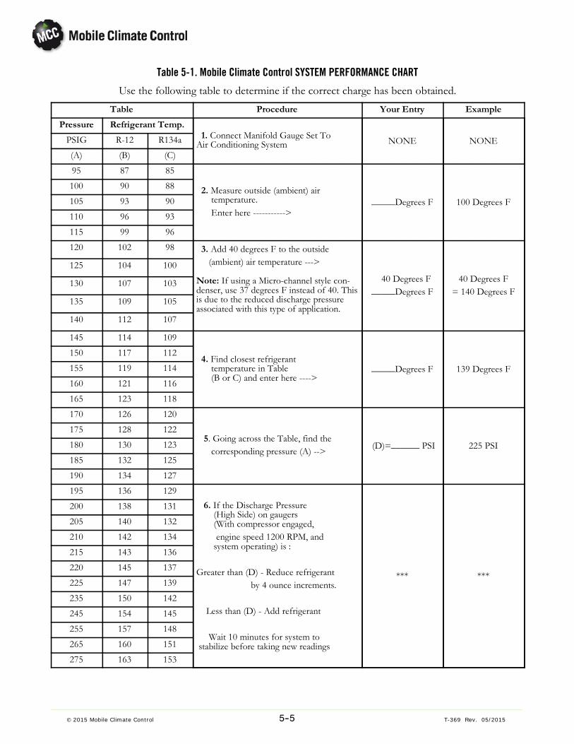
5--5© 2015 Mobile Climate Control T-369 Rev. 05/2015
Table 5-1. Mobile Climate Control SYSTEM PERFORMANCE CHART
Use the following table to determine if the correct charge has been obtained.Table Procedure Your Entry Example
Pressure Refrigerant Temp.1. Connect Manifold Gauge Set ToAir Conditioning System NONE NONEPSIG R-12 R134a
(A) (B) (C)
95 87 85
2. Measure outside (ambient) airtemperature.Enter here ----------->
_____Degrees F 100 Degrees F
100 90 88
105 93 90
110 96 93
115 99 96
120 102 98 3. Add 40 degrees F to the outside(ambient) air temperature --->
Note: If using a Micro-channel style condenser, use 37 degrees F instead of 40. Thisis due to the reduced discharge pressureassociated with this type of application.
40 Degrees F_____Degrees F
40 Degrees F= 140 Degrees F
125 104 100
130 107 103
135 109 105
140 112 107
145 114 109
4. Find closest refrigeranttemperature in Table(B or C) and enter here ---->
_____Degrees F 139 Degrees F
150 117 112
155 119 114
160 121 116
165 123 118
170 126 120
5. Going across the Table, find thecorresponding pressure (A) --> (D)=______ PSI 225 PSI
175 128 122
180 130 123
185 132 125
190 134 127
195 136 1296. If the Discharge Pressure(High Side) on gaugers(With compressor engaged,engine speed 1200 RPM, andsystem operating) is :
Greater than (D) - Reduce refrigerantby 4 ounce increments.
Less than (D) - Add refrigerant
Wait 10 minutes for system tostabilize before taking new readings
*** ***
200 138 131
205 140 132
210 142 134
215 143 136
220 145 137
225 147 139
235 150 142
245 154 145
255 157 148
265 160 151
275 163 153

5--6© 2015 Mobile Climate Control T-369 Rev. 05/2015
5.6.2 Adding Full Charge
a. Installmanifold gauge set at the in-line suction anddischarge service ports.
b. Evacuate and dehydrate system. (Refer to paragraph 5.5)
c. Place appropriate refrigerant cylinder on scales.Prepare to charge liquid refrigerant by connectingcharging hose from container to center connection on gage manifold. Purge air from hoses.
d. Note weight of refrigerant and cylinder.
e. Open cylinder valve, backseat discharge valve ongauge manifold and allow liquid refrigerant to flowinto the high side of the system
f. When correct charge has been added , close cylinder valve and front seat manifold discharge valve.
g. Prepare the cylinder as required to allow vaporcharging. Backseat the manifold suction valve andcharge vapor until the correct charge has beenadded. Close cylinder valve and front seat suctionmanifold set.
h. Check charge level in accordance with the procedures of paragraph 5.6.1.
5.7 CHECKING FOR NONCONDENSIBLES
To check for noncondensibles, proceed as follows:
a. Stabilize system to equalize pressure between thesuction and discharge side of the system.
b. Check temperature at the condenser and receiver.
c. Check pressure at the discharge (in-line) serviceport.
d. Check saturation pressure as it corresponds to thecondenser/receiver temperature. See temperature-Pressure chart Table Table 4-4 for R134a.
e. If gauge reading is 3 psig or more than the calculated P/T pressure in step d., non-condensablesare present.
f. Remove refrigerant using a refrigerant recoverysystem.
g. Evacuate and dehydrate the system. (Refer toparagraph 5.5.)
h. Charge the unit. (Refer to paragraph 5.6.2.)
5.8 FILTER-DRIER
Filter Drier/Receiver
Binary PressureSwitch
Figure 5-3 Filter-Drier
5.8.1 To Check Filter-DrierThe filter-drier (See Figure 5-3) must be changed ifthe system has been opened, (for any reason), or thefilter drier is partially restricted. Restriction can beidentified by either the outlet frosting or atemperature difference between the inlet and outlet.5.8.2 To Replace Filter-Drier AssemblyFilter Drier replacement can be accomplished byperforming the following procedure.a. Remove refrigerant charge. Refer to Section 5.3.1b. Place a new filter-drier near the unit for immediateinstallation.
WARNINGThe filter-drier may contain liquid refrigerant. Slowly loosen the connecting nutsand avoid contact with exposed skin oreyes.
c. Using two open end wrenches, slowly crack openthe connecting nuts on each side of the filter-drierassembly. Loosen clamps retaining drier. Removethe filter-drier assembly.
d. Remove seal caps from the new filter-drier. Applya light coat of mineral oil to the filter-drier connections and O-rings.
e. Assemble the new filter-drier to lines ensuring thedirection of the refrigerant flow (refrigerant flowsfrom the receiver to the evaporator). Finger tighten the connecting nuts. Reinstall retaining clamps.

5--7© 2015 Mobile Climate Control T-369 Rev. 05/2015
f. Tighten filter-drier connecting nuts using twoopen end wrenches.
g. Perform system evacuation (refer to paragraph5.5.3)
h. Recharge system with refrigerant (refer to paragraph 5.6.2)
i. Remove Gauges.
5.9 SERVICING THE HEAT VALVE
The heat valve requires no maintenance unless amalfunction to the internal parts occurs. This may becaused by foreign material such as: dirt, scale, orsludge in the coolant system, or improper voltage tothe coil.j. Open the vent fitting at the top of the outlet header of the heater coil.
k. Drain coil by opening the drain-cock on the inlettube.
l. Disassemble valve and replace defective parts.m.Assemble valve, refill and bleed coolant lines.5.9.1 Replace Entire Valvea. Disconnect system from bus battery.b.Drain coolant from lines as previously describedand disconnect hoses to valve .
c. Disconnect wire leads to valve actuator.d. Remove valve assembly from bracket.e. Install new valve and re-connect hoses. It is notnecessary to disassemble the valve when installing.
f. Refill and bleed coolant lines.g. Connect wire leads and test operation.
Figure 5-4 Heat Valve
5.10 REPLACING RETURN AIR FILTERS
The return air filters are located behind the return airgrill, inside the vehicle.The filters should be checked for cleanlinessperiodically depending on operating conditions. Adirty filter will restrict air flow over the evaporatorcoil which may cause insufficient cooling or heatingand possible frost buildup on the coil. To remove thefilters, do the following.a. Insure air conditioning system is in the off position.
b. Remove the 2 screws retaining the return air grille.c. Remove the air filter and clean or replace..d. Place filter into composite frame, with filter element down (See Figure 5-5).
Figure 5-5 Air Filter
5.11 THERMOSTATIC EXPANSION VALVE
The thermostat expansion valve (Figure 5-6) is anautomatic device which maintains constantsuperheat of the refrigerant gas leaving theevaporator regardless of suction pressure. The valvefunctions are: (a) automatic control of refrigerantflow to match the evaporator load and (b)prevention of liquid refrigerant entering thecompressor. Unless the valve is defective, it seldomrequires any maintenance.
NOTER-134a valves are non-adjustable. Valves arepreset at the factory.

5--8© 2015 Mobile Climate Control T-369 Rev. 05/2015
Figure 5-6 Thermostatic Expansion Valve (Block Valve)
5.11.1 Valve Replacementa. Recover and recycle refrigerant from the system.(refer to 5.3.1)
b. Remove prestite insulation from valve body.c. Loosen refrigerant fittings from valve body.d. Remove mounting screws from retaining bracket.e. Replace valve and install new o-rings to refrigerantfittings. Coat new o-rings with mineral oil beforeinstalling.
f. Reinstallmounting screws to retaining bracket andtighten.
g. Tighten fittings to proper torque (refer toTable 2-1).
h. Leak check connections (refer to paragraph5.4)i. Reinstall prestite insulation on valve body.j. Evacuate/dehydrate system (refer to paragraph5.5.3)
k. Recharge system with refrigerant and check performance. (refer to paragraph 5.6.2)

5--9© 2015 Mobile Climate Control T-369 Rev. 05/2015
Table 4-4 R-134a Temperature - Pressure Chart
Temperature Vacuum
°F °C “/hg cm/hg kg/cm@ bar
-40 -40 14.6 49.4 37.08 0.49
.35 .37 12.3 41.6 31.25 0.42
-30 -34 9.7 32.8 24.64 0.33
-25 -32 6.7 22.7 17.00 0.23
-20 -29 3.5 11.9 8.89 0.12
-18 -28 2.1 7.1 5.33 0.07
-16 -27 0.6 2.0 1.52 0.02
Temperature Pressure
°F °C psig kPa kg/cm@ bar
-14 -26 0.4 1.1 0.03 0.03-12 -24 1.2 8.3 0.08 0.08-10 -23 2.0 13.8 0.14 0.14-8 -22 2.9 20.0 0.20 0.20-6 -21 3.7 25.5 0.26 0.26-4 -20 4.6 31.7 0.32 0.32-2 -19 5.6 36.6 0.39 0.390 -18 6.5 44.8 0.46 0.452 -17 7.6 52.4 0.53 0.524 -16 8.6 59.3 0.60 0.596 -14 9.7 66.9 0.68 0.678 -13 10.8 74.5 0.76 0.7410 -12 12.0 82.7 0.84 0.8312 -11 13.2 91.0 0.93 0.9114 -10 14.5 100.0 1.02 1.0016 -9 15.8 108.9 1.11 1.0918 -8 17.1 117.9 1.20 1.1820 -7 18.5 127.6 1.30 1.2822 -6 19.9 137.2 1.40 1.3724 -4 21.4 147.6 1.50 1.4826 -3 22.9 157.9 1.61 1.58
Temperature Pressure
°F °C psig kPa kg/cm@ bar
28 -2 24.5 168.9 1.72 1.6930 -1 26.1 180.0 1.84 1.8032 0 27.8 191.7 1.95 1.9234 1 29.6 204.1 2.08 2.0436 2 31.3 215.8 2.20 2.1638 3 33.2 228.9 2.33 2.2940 4 35.1 242.0 2.47 2.4245 7 40.1 276.5 2.82 2.7650 10 45.5 313.7 3.20 3.1455 13 51.2 353.0 3.60 3.5360 16 57.4 395.8 4.04 3.9665 18 64.1 441.0 4.51 4.4270 21 71.1 490.2 5.00 4.9075 24 78.7 542.6 5.53 5.4380 27 86.7 597.8 6.10 5.9885 29 95.3 657.1 6.70 6.5790 32 104.3 719.1 7.33 7.1995 35 114.0 786.0 8.01 7.86100 38 124.2 856.4 8.73 8.56105 41 135.0 930.8 9.49 9.31110 43 146.4 1009 10.29 10.09115 46 158.4 1092 11.14 10.92120 49 171.2 1180 12.04 11.80125 52 184.6 1273 12.98 12.73130 54 198.7 1370 13.97 13.70135 57 213.6 1473 15.02 14.73140 60 229.2 1580 16.11 15.80145 63 245.6 1693 17.27 16.93150 66 262.9 1813 18.48 18.13155 68 281.1 1938 19.76 19.37

6--1© 2015 Mobile Climate Control T-369 Rev. 05/2015
SECTION 6
ELECTRICAL
6.1 INTRODUCTIONThis section includes electrical wiring schematics.The schematics shown in this section provides
information for the EcoLine 8 & 10 model rooftopair conditioning units which are fitted with electroniccontrollers.
UNIT CONTROLLER FIGURE NUMBERS
50-1509 Electronic Figure 6-150-1859 Electronic Figure 6-2

6--2© 2015 Mobile Climate Control T-369 Rev. 05/2015
rr
Ref:50-1507S/50-1509S
Figu
re6-
1Ec
oLin
e8
w/El
ectr
onic
Cont
rolle
r(Sp
rinte
r)
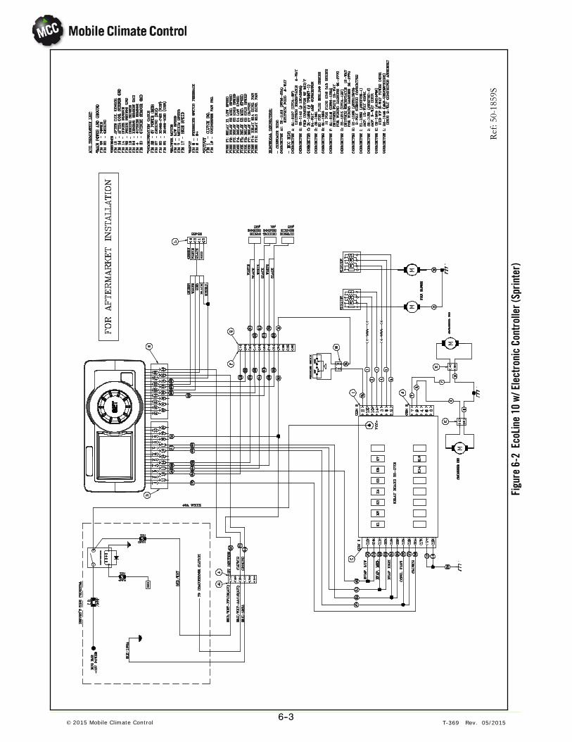
6--3© 2015 Mobile Climate Control T-369 Rev. 05/2015
Ref:50-1859S
Figu
re6-
2Ec
oLin
e10
w/El
ectr
onic
Cont
rolle
r(Sp
rinte
r)

© 2015 Mobile Climate Control T-369 Rev. 05/20157--1
SECTION 7
SERVICE PARTS
INTRODUCTION
This section provides identification of service replacement parts for the Mobile Climate Control EcoFlex andEcoLine products.
CONFIGURATION IDENTIFICATION
Unit identification information is provided on a plate (decal) located on the unit assembly. This plate providesthe unit model number and the unit serial number. The model number identifies the unit configuration anddifferences in detailed parts.
GENERAL NOTES
To find replacement parts, determine major group in which replacement parts are located and turn to theappropriate page for the illustrated breakdown of the replacement parts. The following letter designations areused to classify parts throughout this list. Parts can be obtained by ordering from the following website:
www.mcc-hvac.com
A/R As RequiredN.S. Not Shown on IllustrationNSI Non-Stock Item (Itemsmay not be available for purchase, or may require extended lead times)NSS Not Sold Separately - Order next higher assembly or kit.P-- Suffix P-- added to part number means part is available in packaged quantity only.PL Purchase LocallySS Stainless SteelSV Suffix SV added to part number designates service replacement part.

© 2015 Mobile Climate Control T-369 Rev. 05/20157--2
7.1 MCC EcoLine 8, 12 VDC, Models 50-1509
1
2
3
4
56 7
8 9
10,11
12
13 14
15
16
17
18
Item Part Number Description Qty
1 15-1505 Blower Assembly, 12 VDC 22 15-7503 Fan Assembly, 12 VDC 23 23-0148 Finger Guard 24 21-9023 Coil, Condenser 15 21-9035 Coil, Evaporator 16 22-1122 Coil, Heater 17 25-0781 Terminal Stud, ⅜” 18 35-0763 Relay Board 19 26-0190 Block Valve (TXV) 110 26-8251 Receiver/Drier 1

© 2015 Mobile Climate Control T-369 Rev. 05/20157--3
7.1 MCC EcoLine 8, 12 VDC, Models 50-1509, (Continued):Item Part Number Description Qty
11 25-0308 Pressure Switch, Binary 112 27-0183 Clamp, Gear, 3.4” - 4” (86.4 MM - 101.6 MM) 213 29-0124 Nylon Spacer, ½” 414 28-0005 Grommet, ⅝” 615 28-1905 Cover Assembly 116 26-0652 Motorized Valve Assembly 117 27-3374 Elbow, ⅝” 118 27-3394 Elbow, ⅝” 2NS 27-0601 O-Ring, #6 4NS 27-0602 O-Ring, #8 3NS 27-0603 O-Ring, #10 1
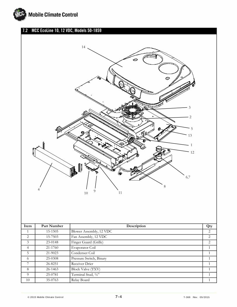
© 2015 Mobile Climate Control T-369 Rev. 05/20157--4
7.2 MCC EcoLine 10, 12 VDC, Models 50-1859
1
2
3
4
5
6,7
8910 11
12
13
14
Item Part Number Description Qty
1 15-1505 Blower Assembly, 12 VDC 22 15-7503 Fan Assembly, 12 VDC 23 23-0148 Finger Guard (Grille) 24 21-1760 Evaporator Coil 15 21-9023 Condenser Coil 16 25-0308 Pressure Switch, Binary 17 26-8251 Receiver Drier 18 26-1463 Block Valve (TXV) 19 25-0781 Terminal Stud, ⅜” 110 35-0763 Relay Board 1

© 2015 Mobile Climate Control T-369 Rev. 05/20157--5
7.2 MCC EcoLine 10, 12 VDC, Model 50-1859, (Continued):Item Part Number Description Qty
11 29-0124 Nylon Spacer, ½” 412 27-0183 Clamp, Gear, 3.4” - 4” (86.4 MM - 101.6 MM) 213 28-0005 Grommet, ⅝” (15.9 MM) 614 28-1905 Cover Assembly 1NS 27-0601 O-Ring, #6 4NS 27-0602 O-Ring, #8 3NS 27-0603 O-Ring, #10 1

© 2015 Mobile Climate Control T-369 Rev. 05/20157--6
7.3 MCC EcoLine Electrical Panel, Y25-00090-00
1
2
3
4
5
6 6
7
Item Part Number Description Qty
1 Y25-00001-05 Relay, 24 VDC 12 Y35-00021-00 Contactor 13 25-2553 Circuit Breaker 14 201-901 Connector, Relay Socket 15 201-931 Lock, Relay 16 22-02336-02 Fuse, 5A 27 22-02336-04 Fuse, 10A 1
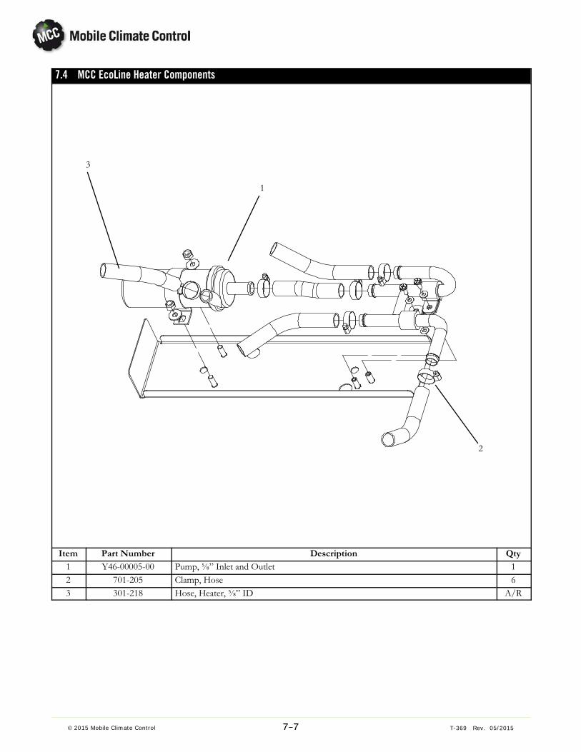
© 2015 Mobile Climate Control T-369 Rev. 05/20157--7
7.4 MCC EcoLine Heater Components
1
2
3
Item Part Number Description Qty
1 Y46-00005-00 Pump, ⅝” Inlet and Outlet 12 701-205 Clamp, Hose 63 301-218 Hose, Heater, ⅝” ID A/R

Index --1© 2015 Mobile Climate Control T-369 Rev. 05/2015
PARTS INDEX
115-1505 7-2, 7-415-7503 7-2, 7-4
2201-901 7-6201-931 7-621-1760 7-421-9023 7-2, 7-421-9035 7-222-02336-02 7-622-02336-04 7-622-1122 7-223-0148 7-2, 7-425-0308 7-3, 7-425-0781 7-2, 7-425-2553 7-626-0190 7-226-0652 7-326-1463 7-426-8251 7-2, 7-4
27-0183 7-3, 7-527-0601 7-3, 7-527-0602 7-3, 7-527-0603 7-3, 7-527-3374 7-327-3394 7-328-0005 7-3, 7-528-1905 7-3, 7-529-0124 7-3, 7-5
3301-218 7-735-0763 7-2, 7-4
7701-205 7-7
YY25-00001-05 7-6Y35-00021-00 7-6Y46-00005-00 7-7

3189 Farmtrail RoadYork PA 17406 USATel: 1--800--673--2431Fax: 1--717--764--0401
MCC provides exceptional performance in mobile climate comfort.
Every driver deserves the best possiblevehicle climate with MCC products
www.mcc-hvac.comMember of MCC Group S Certified ISO 9001 and ISO 1 4001.
Specifications subject to change without notice. MCC is a registered trademark.
© 2015 Mobile Climate Control T-369 Rev. 05/2015