OPERATION MANUAL - Stud Welding Products, Inc. Manual_Updated.pdfOPERATION MANUAL MODELS TWE-250...
33
OPERATION MANUAL MODELS StudPro 2500 StudPro 3125 StudPro 3750 Downey, CA 9459 Washburn Rd. Downey, CA 90242 Phone- 800.252.1919 Fax- 562.862.3022 Hayward, CA 2391 American Ave. Hayward, CA 94545 Phone- 510.782.7883 Fax- 510.782.7918 Renton, WA 927 Thomas Ave. SW Renton, WA 98057 Phone- 425.656.9787 Fax- 425.656.9786 Phoenix, AZ 3535 East Wier Ave., Ste. #4 Phoenix, AZ 85040 Phone- 602.305.9350 Fax- 602.305.4890 Toll free customer support: 1.800.252.1919
Transcript of OPERATION MANUAL - Stud Welding Products, Inc. Manual_Updated.pdfOPERATION MANUAL MODELS TWE-250...

OPERATION MANUAL
MODELSTWE-250TWE-321TWE-375
TRU‐WELD EQUIPMENT COMPANY
6400 N. HONEYTOWN ROAD
SMITHVILLE, OHIO 44677
(330) 669‐2773
MODELSStudPro 2500StudPro 3125StudPro 3750
Downey, CA9459 Washburn Rd.Downey, CA 90242Phone- 800.252.1919Fax- 562.862.3022
Hayward, CA2391 American Ave.Hayward, CA 94545Phone- 510.782.7883Fax- 510.782.7918
Renton, WA927 Thomas Ave. SWRenton, WA 98057Phone- 425.656.9787Fax- 425.656.9786
Phoenix, AZ3535 East Wier Ave., Ste. #4Phoenix, AZ 85040Phone- 602.305.9350Fax- 602.305.4890
Toll free customer support: 1.800.252.1919
22
CONTENTS
Section Description Pages
1 Introduction 3
2 External Features 4‐5
3 Safety 6‐8
4 Setup and Welding 9‐15
5 Testing Weld Settings 16
6 Inspecting The Weld 17
7 CD Stud Gun Views 18
8 CD Stud Gun Exploded View 19
9 CD Stud Gun Parts List 20
10 CD Controller Exploded View 21
11 CD Controller Parts List 22
1 Introduction 3 2 External Features 4-5 3 Safety 6-8 4 SetupandWelding 9-15 5 TestingWeldSettings 16-19 6 TypesofFractures 20 7 ArcBlowEffect 21 8 CDStudGunExplodedView 22 9 InternalComponents 23-25 10 CDAccessoreis 26-29 11 TorqueBendingTest 30-31 12 CDGunSetUp’s 32-33

33
The complete range of the capacitor discharge equipment is compact, portable stud
welding equipment. The units are specifically designed to enable a small diameter
range of ferrous and nonferrous weld studs to be welded to light gauge metal materi‐
als with little or no reverse‐side marking.
The equipment consists of a control unit, a welding hand gun, and all necessary inter‐
connecting cables.
THE PROCESS
Capacitor Discharge (CD) stud welding is a form of welding in which the energy re‐
quired for the welding process is derived from a bank of charged capacitors. This
stored energy is discharged at the base of the specially designed CD stud and it fuses
the stud to the base material. The time of the weld is determined in such a short du‐
ration that no burn through marking is made on the finish side of the material.
CONTACT
In contact CD welding, the stud is placed under spring pressure on the material to be
welded. When the capacitors are discharged, the special tip of the CD stud melts and
the spring pressure forces the stud to fuse with the base material.
GAP
In gap CD welding, the stud is placed onto the material to be welded. As the stud gun
is engaged, the stud lifts from the base material and then returns to the point of con‐
tact at the time of the discharge of the capacitors. As the capacitors discharge, melt‐
ing the tip of the weld stud, the pressure created by the movement of the stud to the
base material by the stud gun fuses the stud to the base material.
INTRODUCTION

44
FRONT PANEL
1. Weld Voltage Selector ‐ rotate to change to required voltage.
2. Welding Voltage Digital Display ‐ displays selected voltage.
3. LED Lights ‐ Charging (capacitors are being charging to desired voltage), Ready
(unit is ready to weld), Reset (indicates an error and unit should be turned off).
4. Welding Ground Cable Connector (+)
5. Stud Gun Control Connector
6. Welding Stud Gun Cable Connector (‐)
EXTERNAL FEATURES
1
4
2
5 6
3
1
2
3
654

55
REAR PANEL
1.On/Off Switch
2.Fuse Holder (10 amp)
3.AC Power Cord
4.Manufacturer Model Number and Serial Number Plate
WARNING!
This unit operates from a 110 VAC 60 Hertz @10 amp circuit.
Do not obstruct the ventilation fan, as this may cause unit to over heat.
Do not remove any portion of the unit housing without first disconnecting the unit
from the power supply.
EXTERNAL FEATURES
ON/OFF Switch
15Amp Fuse
Power Supply Fan
AC Cord
ON/OFF Switch
15Amp Fuse
Power Supply Fan
AC Cord

66
PROTECT YOURSELF AND OTHERS!
Read the safety notices before using welder.
ELECTRICAL
No portion of the outer cover of the welding controller should be removed by any‐
one other than qualified personnel. Always disconnect the unit from the main power
prior to removing cover.
• This equipment contains a transformer power supply system, which is energized
by AC current and transforms the AC to DC current. Due to potential dangerous
electrical input and output the equipment must be disconnected from all incom‐
ing power when servicing.
• Capacitors store electrical energy. Check for residual charge before performing
any maintenance.
• Do not use fluids to clean electrical components as these may penetrate the elec‐
trical system and cause shorts.
Connection of the unit into service must be in accordance with the setup procedures
as detailed in this manual. Operation of this equipment must be in accordance with
all local, regional, and national safety codes.
SAFETY

77
FIRE
During welding, small particles of hot metal can be expelled. Ensure that no combus‐
tible materials are near the welding area.
PERSONAL SAFETY
Arc rays can burn your eyes and skin. Wear protective clothing and eye protection
when welding.
Loud noises from welding can damage hearing. Wear earplugs or other protective
gear, if applicable.
Fumes and gases expelled during welding can be hazardous to your health. Make
sure welding is done in a well‐ventilated area.
Hot metal splatter can cause fires and burns. Wear protective clothing, free of com‐
bustible materials. Have a fire extinguisher nearby and know how to use it.
MAINTENANCE
All cables must be inspected regularly to ensure that no danger exists from worn or
damaged insulation or unsafe electrical connections. Take special note to the cables
near the stud gun ‐ this is where maximum wear occurs.
Worn cables not only produce inconsistent welds, but can overheat or spark.
SAFETY
FIRE HAZARD FROM SPARKS

88
TRAINING
Use of this equipment must be limited to authorized personnel only. They must be
adequately trained, and have read and understood everything in this manual. The
manual must be available to operators at all times.
INSTALLATION
Select a site for the equipment which is capable of supporting the weight of the
equipment, which is clear from traffic routes where people may trip over cables, or
they may be damaged by other equipment or vehicles.
Do not hang connecting cables over sharp edges or have near heat sources.
DISPOSAL
The equipment, in its entirety or as components/parts may be disposed of as general
industrial waste or scrap. None of the components used in the manufacturing of the
CD Welders are toxic, carcinogenic, or otherwise harmful to your health.
SAFETY
AUTHORIZEDPERSONNEL ONLY

99
POWERING UP THE EQUIPMENT
Setup the equipment power supply (Control Unit) and connect to the main power,
making certain of the proper voltage requirement of the particular unit.
Capacitor Discharge (CD) units generally require 110 VAC @ 60Hz incoming power.
Refer to the safety recommendations before plugging this unit in.
ON/OFF Switch
Fuse
Power Cord (110 VAC)
CONNECTING THE WELDING LEADS
Connect the welding ground cable into the (+) terminal mount socket on the front of
the welding unit.
***NOTE ‐ the cable end plug has a flat which aligns with a dot on the panel mount
socket. Secure the connector into the panel mount socket, and then turn it clockwise
until it locks into proper position. Failure to do so could result in damage to the con‐
nector.
Ground Cable Socket
SET-UP AND WELDING
Ground Cable Socket
ON/OFF Switch
Fuse
Power Cord (110 VAC)

1010
CONNECTING THE WELDING LEADS
Connect the welding stud gun power cable into the (‐) terminal panel mount socket
(designated by the gun symbol) on the front of the welding unit.
***NOTE ‐ the cable end plug has a flat which aligns with a dot on the panel mount
socket. Secure the connector into the panel mount socket, and then turn it clockwise
until it locks into proper position. Failure to do so could result in damage to the con‐
nector.
Welding Gun Power Connector
Welding Gun Control Cable Connector
Connect the weld gun control cable into the center panel 2‐pin socket.
**NOTE ‐ the plug has a large pin and a small pin that match the socket on the unit.
This is to prevent incorrect connections. Push the plug firmly into the socket and
twist clockwise to secure the plug into the correct position.
SET-UP AND WELDING
Welding Gun Control Cable Connector
Welding Gun Power Connector

1111
CONNECTING THE GROUND CLAMP
Attach the clamp of the welding ground lead to the work piece. Prior to securing the
clamp, make certain that the contact area is free of rust, paint, grease, or any other
impurities to ensure a good ground connection.
NOTE***Most applications will require only one ground clamp, but certain applica‐
tions will require an additional dual clamp.
SET-UP AND WELDING
13
CONNECTING THE GROUND CLAMP Attach the clamp of the welding ground lead to the work piece. Prior to securing the clamp, make certain that the contact area is free of rust, paint, grease, or any other impurities to ensure a good ground connection.
NOTE***Most applications will require only one ground clamp, but certain applica‐tions will require an additional dual clamp.
SET-UP AND WELDING

12
14
SELECTING THE PROPER STUD COLLET (STUD HOLDER) The collet is selected to the proper diameter that you are welding.
There are three styles of collets;
• The “B” collet which is a two‐piece assembly (collet and insert). The insert deter‐mines how much of the stud is engaged in the collet.
• The CI (Collet Insert) which is a single part and the amount of the stud that is en‐gaged is predetermined.
• Standard Adjustable Chucks have an adjustable internal screw to manually adjust for the engagement of the stud.
The choice between these systems is usually a matter of personal preference.
Inserting the selected collet into the stud gun is a simple task. Place the collet into the front holder of the stud gun and set the locking screws to hold it in place.
After inserting the collet, mount the two legs and foot piece onto the stud gun. The collet should be centered through the opening of the foot piece.
When the legs and foot piece are in place, insert the stud to be welded into the col‐let. Adjust the leg and foot piece by sliding it into position until approximately 1/8” of the stud protrudes from beyond the foot piece. Lock legs in place with the set screws.
SET-UP AND WELDING
Foot Piece
Collet
Leg Piece
12
SELECTING THE PROPER STUD COLLET (STUD HOLDER)
The collet is selected to the proper diameter that you are welding.
There are three styles of collets;
• The “B” collet which is a two‐piece assembly (collet and insert). The insert deter‐
mines how much of the stud is engaged in the collet.
• The CI (Collet Insert) which is a single part and the amount of the stud that is en‐
gaged is predetermined.
• Standard Adjustable Chucks have an adjustable internal screw to manually adjust
for the engagement of the stud.
The choice between these systems is usually a matter of personal preference.
Inserting the selected collet into the stud gun is a simple task. Place the collet into
the front holder of the stud gun and set the locking screws to hold it in place.
After inserting the collet, mount the two legs and foot piece onto the stud gun. The
collet should be centered through the opening of the foot piece.
When the legs and foot piece are in place, insert the stud to be welded into the col‐
let. Adjust the leg and foot piece by sliding it into position until approximately 1/8”
of the stud protrudes from beyond the foot piece. Lock legs in place with the set
screws.
SET-UP AND WELDING
Foot Piece
Collet
Leg Piece

1313
SELECTING THE SPRING LOAD
The proper spring pre‐load setting on the stud gun will vary depending on the se‐
lected application. Generals rules of application would be; mild steel or stainless
steel usually in the 1 to 2 range, depending on the stud diameter and the thickness of
the base material. Aluminum and other nonferrous metals would require settings
from 3 to 5 depending on the diameter of the stud and base material thickness.
This spring pre‐load adjustment is made by turning the screw insert in the back of the
stud gun with a screwdriver. On the bottom of the back cap of the stud gun is the
indicator numbered 1 thru 5, which will show you the tension setting during the ad‐
justment.
SET-UP AND WELDING
Adjustment Screw
Tension Indicator
15
SELECTING THE SPRING LOAD The proper spring pre‐load setting on the stud gun will vary depending on the se‐lected application. Generals rules of application would be; mild steel or stainless steel usually in the 1 to 2 range, depending on the stud diameter and the thickness of the base material. Aluminum and other nonferrous metals would require settings from 3 to 5 depending on the diameter of the stud and base material thickness.
This spring pre‐load adjustment is made by turning the back cap of the stud gun. On the side of the stud gun is the indicator numbered 1 thru 5, which will show you the tension setting during the adjustment.
SET-UP AND WELDING
Adjustment Cap
Tension Indicator
Location of adjustment on back of the gun.

1414
READY FOR WELDING
When you have completed all of the previous steps to prepare for welding, including
connecting the stud gun and ground cables to the unit, attaching the ground cable(s)
to the work area, setting up and adjusting the stud gun for the selected stud diame‐
ter and material, you can now power on the welder.
The controller ON/OFF switch is located on the rear of the unit in the upper right
hand corner. Below this switch is the 15amp fuse holder for the system.
SET-UP AND WELDING
ON/OFF SWITCH
FUSE
ON/OFF Switch
FUSE

1515
VOLTAGE SELECTION
Selecting the required weld voltage is achieved by turning the selector knob. The
voltage range is from 35VDC to 200VDC.
The voltage is determined by the diameter of the stud and the base material.
Approximate voltage staring points are listed below. Fine tuning the voltage to meet
your requirement for your specific application is recommended.
NOTE***when welding cupped‐head insulation pins, set the DC Voltage to 35 volts to
begin and increase as necessary. Adjust the spring pressure on the CD gun between
#1 and #3 as necessary.
SET-UP AND WELDING
Diameter Voltage (DC)
14 ga. 50‐75
12 ga. 75‐110
#8 110‐130
#10 125‐160
1/4” 160‐190
Diameter Voltage (DC)
14 ga. 35‐50
12 ga. 50‐75
#8 75‐100
#10 100‐120
1/4” 120‐140
MODEL TWE‐321 & 375
3/8” (TWE‐375) 160‐200
5/16” 140‐160
Voltage Adjustment Knob
MODEL STUDPRO 2500
VOLTAGE SELECTION
Selecting the required weld voltage is achieved by turning the selector knob. The
voltage range is from 35VDC to 200VDC.
The voltage is determined by the diameter of the stud and the base material.
Approximate voltage staring points are listed below. Fine tuning the voltage to meet
your requirement for your specific application is recommended.
NOTE***when welding cupped‐head insulation pins, set the DC Voltage to 35 volts to
begin and increase as necessary. Adjust the spring pressure on the CD gun between
#1 and #3 as necessary.
SET-UP AND WELDING
Diameter Voltage (DC)
14 ga. 50‐75
12 ga. 75‐110
#8 110‐130
#10 125‐160
1/4” 160‐190
Diameter Voltage (DC)
14 ga. 35‐50
12 ga. 50‐75
#8 75‐100
#10 100‐120
1/4” 120‐140
MODEL TWE‐321 & 375
3/8” (TWE‐375) 160‐200
5/16” 140‐160
Voltage Adjustment Knob
MODEL 3125 & 3750
(3750)
Voltage Adjustment Knob
16
18
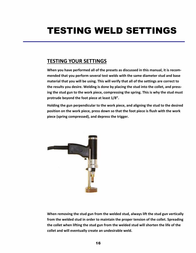
TESTING YOUR SETTINGS When you have performed all of the presets as discussed in this manual, it is recom‐mended that you perform several test welds with the same diameter stud and base material that you will be using. This will verify that all of the settings are correct to the results you desire. Welding is done by placing the stud into the collet, and press‐ing the stud gun to the work piece, compressing the spring. This is why the stud must protrude beyond the foot piece at least 1/8”.
Holding the gun perpendicular to the work piece, and aligning the stud to the desired position on the work piece, press down so that the foot piece is flush with the work piece (spring compressed), and depress the trigger.
When removing the stud gun from the welded stud, always lift the stud gun vertically from the welded stud in order to maintain the proper tension of the collet. Spreading the collet when lifting the stud gun from the welded stud will shorten the life of the collet and will eventually create an undesirable weld.
TESTING WELD SETTINGS

1717
INSPECTING THE WELD
Visually inspect the weld. A good weld will result in an all‐around weld, with a small
visible amount of weld surrounding the flange of the stud. Too much splatter and the
weld is too hot, lower the voltage. No splatter and the weld is too cold, increase the
voltage.
If you get weld flash to one side of the stud as opposed to an even amount around
the base of the flange, this is called “arc blow”, and can be solved by repositioning
the ground clamp or using a dual ground clamp.
Proper welded studs can be tested by either torquing or bending the stud. The
welded flange of the stud should stay in place using either method, even though the
threaded portion of the stud breaks. If the base material is very thin, then a full slug,
the diameter of the flange will pull from the base metal for a properly welded stud.
CD Stud Welding Steps
SET-UP AND WELDING
TESTING YOUR SETTINGS
When you have performed all of the presets as discussed in this manual, it is recom‐
mended that you perform several test welds with the same diameter stud and base
material that you will be using. This will verify that all of the settings are correct to
the results you desire. Welding is done by placing the stud into the collet, and press‐
ing the stud gun to the work piece, compressing the spring. This is why the stud must
protrude beyond the foot piece at least 1/8”.
Holding the gun perpendicular to the work piece, and aligning the stud to the desired
position on the work piece, press down so that the foot piece is flush with the work
piece (spring compressed), and depress the trigger.
When removing the stud gun from the welded stud, always lift the stud gun vertically
from the welded stud in order to maintain the proper tension of the collet. Spreading
the collet when lifting the stud gun from the welded stud will shorten the life of the
collet and will eventually create an undesirable weld.
TESTING WELD SETTINGS

1818
CD 2301 Order No. BA 92-12-0231A Issue 05.01.10 31
5.8.1 Visual Inspection
A visual inspection must be carried out with each welding element.
Condition Possible cause Corrective actionsGood welded jointLow spatters around the weld without outer flawsThe weld pool forms a collar around the flange of about 1 - 1,5 mm
- Correct parameters - None
Cold weld poolGap between flange and workpiece
- Heat input too low- Plunging speed too low- No sufficient backing of workpiece
- Increase charging voltage- Adjust plunging speed correctly- Provide sufficient backing
Hot weld poolMany spatters around the weld
- Heat input too high- Plunging speed too low
- Reduce charging voltage- Increase plunging speed
One-sided weld poolOne-sided spatter collarWeld pool came out on one side
- Arc blow effect- Unsymmetric ground connection- Welding gun put at an angle
- Take care for symmetrical ground connection- Put welding gun vertically to the workpiece
Visual Inspection
5 Stud Welding Procedure
5.8 Checking the Quality of the Weld
TESTING YOUR SETTINGS
When you have performed all of the presets as discussed in this manual, it is recom‐
mended that you perform several test welds with the same diameter stud and base
material that you will be using. This will verify that all of the settings are correct to
the results you desire. Welding is done by placing the stud into the collet, and press‐
ing the stud gun to the work piece, compressing the spring. This is why the stud must
protrude beyond the foot piece at least 1/8”.
Holding the gun perpendicular to the work piece, and aligning the stud to the desired
position on the work piece, press down so that the foot piece is flush with the work
piece (spring compressed), and depress the trigger.
When removing the stud gun from the welded stud, always lift the stud gun vertically
from the welded stud in order to maintain the proper tension of the collet. Spreading
the collet when lifting the stud gun from the welded stud will shorten the life of the
collet and will eventually create an undesirable weld.
TESTING WELD SETTINGS
1919
32 CD 2301 Order No. BA 92-12-0231A Issue 05.01.10
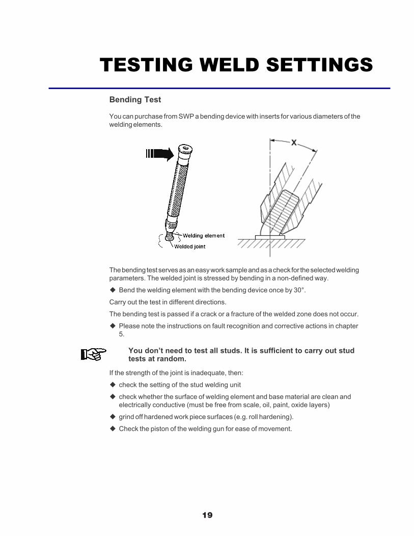
5.8.2 Bending Test
You can purchase from SWP a bending device with inserts for various diameters of thewelding elements.
The bending test serves as an easy work sample and as a check for the selected weldingparameters. The welded joint is stressed by bending in a non-defined way.
Bend the welding element with the bending device once by 30°.
Carry out the test in different directions.
The bending test is passed if a crack or a fracture of the welded zone does not occur.
Please note the instructions on fault recognition and corrective actions in chapter5.
You don’t need to test all studs. It is sufficient to carry out studtests at random.
If the strength of the joint is inadequate, then:
check the setting of the stud welding unit
check whether the surface of welding element and base material are clean andelectrically conductive (must be free from scale, oil, paint, oxide layers)
grind off hardened work piece surfaces (e.g. roll hardening).
Check the piston of the welding gun for ease of movement.
5 Stud Welding Procedure
5.8 Checking the Quality of the Weld
TESTING YOUR SETTINGS
When you have performed all of the presets as discussed in this manual, it is recom‐
mended that you perform several test welds with the same diameter stud and base
material that you will be using. This will verify that all of the settings are correct to
the results you desire. Welding is done by placing the stud into the collet, and press‐
ing the stud gun to the work piece, compressing the spring. This is why the stud must
protrude beyond the foot piece at least 1/8”.
Holding the gun perpendicular to the work piece, and aligning the stud to the desired
position on the work piece, press down so that the foot piece is flush with the work
piece (spring compressed), and depress the trigger.
When removing the stud gun from the welded stud, always lift the stud gun vertically
from the welded stud in order to maintain the proper tension of the collet. Spreading
the collet when lifting the stud gun from the welded stud will shorten the life of the
collet and will eventually create an undesirable weld.
TESTING WELD SETTINGS

2020
CD 2301 Order No. BA 92-12-0231A Issue 05.01.10 33
Type of fracture Possible cause Corrective actionsBase material buckling - Correct parameters - none
Fracture in the welding elementabove flange
- Correct parameters - none
Fracture in the weld metal - Heat input too low- Plunging speed too low- Welding element/base material combination not suitable
- Increase charging voltage- Increase plunging speed- Replace welding element or workpiece
Backside deformation - Heat input too high- Pressure too high- Contact stud welding not suitable- Workpiece too thin
- Reduce charging voltage- Reduce pressure- Use gap stud welding instead of contact stud welding- Adapt thickness of workpiece
Bending Test
5 Stud Welding Procedure
5.8 Checking the Quality of the Weld
INSPECTING THE WELD
Visually inspect the weld. A good weld will result in an all‐around weld, with a small
visible amount of weld surrounding the flange of the stud. Too much splatter and the
weld is too hot, lower the voltage. No splatter and the weld is too cold, increase the
voltage.
If you get weld flash to one side of the stud as opposed to an even amount around
the base of the flange, this is called “arc blow”, and can be solved by repositioning
the ground clamp or using a dual ground clamp.
Proper welded studs can be tested by either torquing or bending the stud. The
welded flange of the stud should stay in place using either method, even though the
threaded portion of the stud breaks. If the base material is very thin, then a full slug,
the diameter of the flange will pull from the base metal for a properly welded stud.
CD Stud Welding Steps
SET-UP AND WELDING TYPES OF FRACTURES

2121
34 CD 2301 Order No. BA 92-12-0231A Issue 05.01.10
5.8.3 Arc Blow Effect
A so called arc blow effect can occur with unproportionally distributed ground connec-tions in relation to the base material mass, varying material distribution, or welding atthe edge of a work piece. This is an undesired deflection of the arc. It causes a single-sided melting of the stud material, increased pore formation, and undercuts in thewelding area.
The arc blow effect is proportional to the current and can be influenced by symmetricinstallation of the ground clamps, by fitting of compensation masses, or by rotating thewelding gun around its vertical axis (applies for welding guns with external weldingcable).
Arc blow effects and some corrective actions(according to standards, see appendix)
Cause Corrective action
5 Stud Welding Procedure
5.8 Checking the Quality of the Weld
INSPECTING THE WELD
Visually inspect the weld. A good weld will result in an all‐around weld, with a small
visible amount of weld surrounding the flange of the stud. Too much splatter and the
weld is too hot, lower the voltage. No splatter and the weld is too cold, increase the
voltage.
If you get weld flash to one side of the stud as opposed to an even amount around
the base of the flange, this is called “arc blow”, and can be solved by repositioning
the ground clamp or using a dual ground clamp.
Proper welded studs can be tested by either torquing or bending the stud. The
welded flange of the stud should stay in place using either method, even though the
threaded portion of the stud breaks. If the base material is very thin, then a full slug,
the diameter of the flange will pull from the base metal for a properly welded stud.
CD Stud Welding Steps
SET-UP AND WELDING ARC BLOW EFFECT

22 23
CD Gun Exploded View

23
20
Internal Components
1.
2.
1. TWE01013 ‐‐‐ CD Rocker switch
6. 5. 4.
3.
2. TWE01012 ‐‐‐ CD 15 Amp Breaker
3. TWE0851CD ‐‐‐ AC Inline Filter
4. TWE01004 ‐‐‐ Capacitor (2)
5. TWE103621‐005 ‐‐‐ CD Capacitor Bracket
6. TWE103621‐006 ‐‐‐ CD Capacitor Bridge Link

24 21
Internal Components
1. 2.
1. TWE01001 ‐‐‐ PC Board
6. 5. 4. 3.
2. TWE01002/TWE01003 ‐‐‐ CD Thyristor /Clamp
3. TWE01011‐‐‐ CD Flyback Diode
4. TWE01010 ‐‐‐ CD TRIAC
5. TWE01009 ‐‐‐ CD Bridge Rectifier
6. TWE01015 ‐‐‐ CD Fan
7. 8. 10. 11.
7. TWE01019 ‐‐‐ CD Terminal Block
8. TWE01006 ‐‐‐ Main Wire Harness
9. TWE01014 ‐‐‐ Power Relay
10. TWE01005 ‐‐‐ CD Main Transformer
10. TWE01008 ‐‐‐ CD Power Resistor
9.
25 22
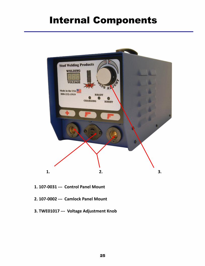
Internal Components
1. 107‐0031 ‐‐‐ Control Panel Mount
2. 107‐0002 ‐‐‐ Camlock Panel Mount
3. TWE01017 ‐‐‐ Voltage Adjustment Knob
1. 2. 3.

2628
13
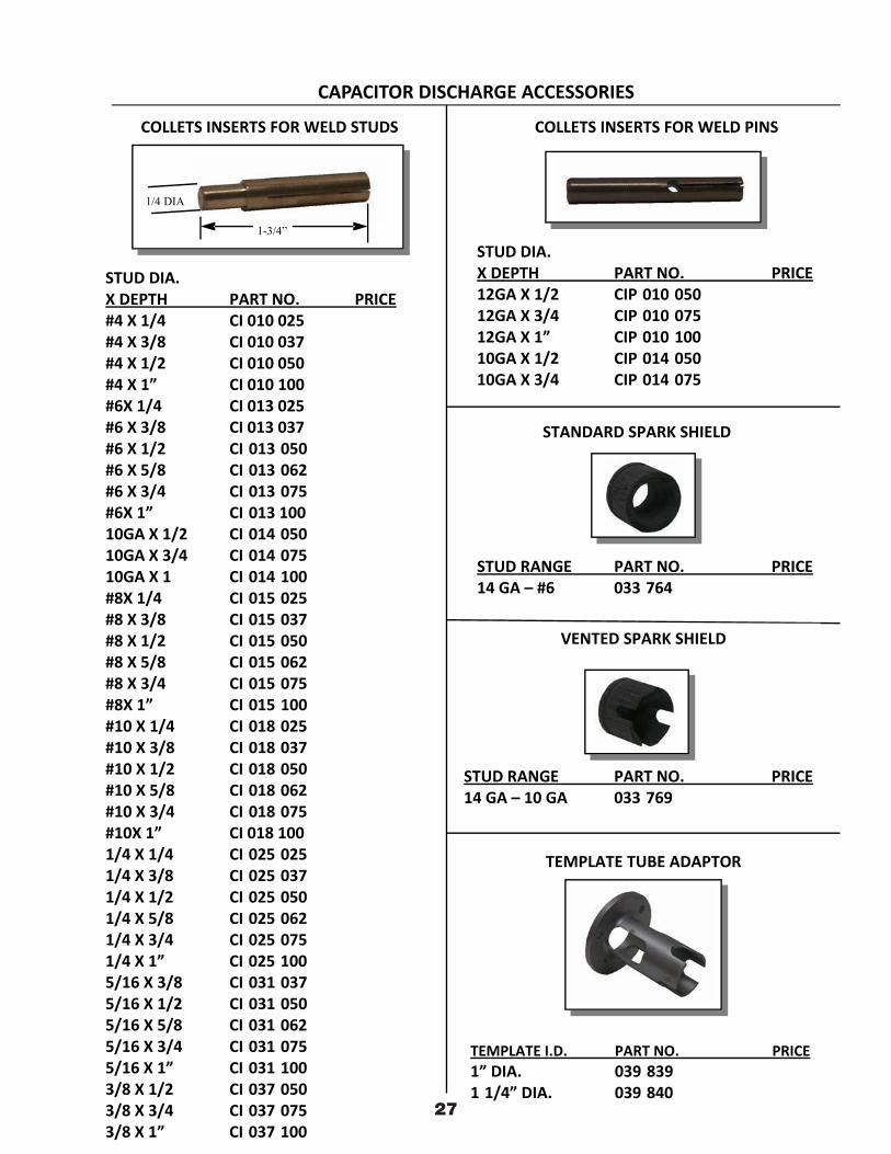
CAPACITOR DISCHARGE ACCESSORIES
ONE PIECE CONTACT/MAGNETIC CHUCK
PART NO. PRICE039 613 36.00
“B” COLLETS PROTECTOR
STUD SIZE PART NO. PRICE14 GA X 12 GA 028 837 23.0010 GA 028 838 23.00BODY ONLY 028 836 20.0012 GA INSERT 028 834 4.0010 GA INSERT 028 835
“B” STOP
STUD STOP PART NO. PRICE1/4 1 1/4 033 781 3.503/8 1 1/8 033 782 3.501/2 1” 033 783 3.505/8 7/8 033 784 3.503/4 3/4 033 785 3.507/8 5/8 033 775 3.501” 1/2 033 776 3.501 1/8 3/8 033 777 3.501 1/4 1/4 033 778 3.501 3/8 (BUTTON STOP) 1/8 033 779 3.50UNIVERSAL 033 780 3.50
SHORT BUTTON STOP
UNIVERSAL “B” STOP
MAGNETIC CHUCK
PART NO. DESCRIPTION PRICE035 301 COMPLETE ASSY 49.00017 633 MAGNET ONLY 40.00029 615 CONDUCTOR PLATE 20.00039 609 INSUL. TUBE 9.00039 610 INSUL. DISC 9.00SCREW 10 32 X 7/8 9.00
14
TEMPLATE TUBE ADAPTOR
STUD RANGE PART NO. PRICE14 GA – #6 033 764 18.00
STANDARD SPARK SHIELD
STUD DIA.X DEPTH PART NO. PRICE#4 X 1/4 CI 010 025 18.00#4 X 3/8 CI 010 037 18.00#4 X 1/2 CI 010 050 18.00#4 X 1” CI 010 100 18.00#6X 1/4 CI 013 025 18.00#6 X 3/8 CI 013 037 18.00#6 X 1/2 CI 013 050 18.00#6 X 5/8 CI 013 062 18.00#6 X 3/4 CI 013 075 18.00#6X 1” CI 013 100 18.0010GA X 1/2 CI 014 050 18.0010GA X 3/4 CI 014 075 18.0010GA X 1 CI 014 100 18.00#8X 1/4 CI 015 025 18.00#8 X 3/8 CI 015 037 18.00#8 X 1/2 CI 015 050 18.00#8 X 5/8 CI 015 062 18.00#8 X 3/4 CI 015 075 18.00#8X 1” CI 015 100 18.00#10 X 1/4 CI 018 025 18.00#10 X 3/8 CI 018 037 18.00#10 X 1/2 CI 018 050 18.00#10 X 5/8 CI 018 062 18.00#10 X 3/4 CI 018 075 18.00#10X 1” CI 018 100 18.001/4 X 1/4 CI 025 025 18.001/4 X 3/8 CI 025 037 18.001/4 X 1/2 CI 025 050 18.001/4 X 5/8 CI 025 062 18.001/4 X 3/4 CI 025 075 18.001/4 X 1” CI 025 100 18.005/16 X 3/8 CI 031 037 25.005/16 X 1/2 CI 031 050 25.005/16 X 5/8 CI 031 062 25.005/16 X 3/4 CI 031 075 25.005/16 X 1” CI 031 100 25.003/8 X 1/2 CI 037 050 25.003/8 X 3/4 CI 037 075 25.003/8 X 1” CI 037 100 25.00
COLLETS INSERTS FOR WELD STUDS
CAPACITOR DISCHARGE ACCESSORIES
COLLETS INSERTS FOR WELD PINS
STUD RANGE PART NO. PRICE14 GA – 10 GA 033 769 20.00
VENTED SPARK SHIELD
TEMPLATE I.D. PART NO. PRICE1” DIA. 039 839 333.001 1/4” DIA. 039 840 333.00
STUD DIA.X DEPTH PART NO. PRICE12GA X 1/2 CIP 010 050 18.0012GA X 3/4 CIP 010 075 18.0012GA X 1” CIP 010 100 18.0010GA X 1/2 CIP 014 050 18.0010GA X 3/4 CIP 014 075 18.00
1-3/4”
1/4 DIA
2927

2830
15
STUD SIZE PART NO. OTHER PART # PRICE#6 CDBN 013 500 001 356 17.00#8 CDBN 015 500 001 357 17.00#10 CDBN 018 500 001 366 17.001/4 CDBN 025 500 001 359 17.005/16 CDBN 031 500 001 360 22.004 MM CDBN 004M 500 001 361 22.006 MM CDBN 006M 500 001 362 22.0012 GA CDBN 010 500 001 363 22.00
STUD LENGTH PART NO. PRICE1/4 TO 5/8 500 017 017 16.003/4 TO 1 1/8 500 017 018 16.001 1/4 TO 1 5/8 500 017 019 16.001 3/4 TO 2 1/8 500 017 020 16.00
BOTTOM LOAD
STUD DIA PART NO. PRICE#4 (.112) 016 412#6 (.138) 016 415#8 (.164) 016 416#10 (.189) 004 684
RAM FEED
STUD DIA PART NO. PRICE#4 (.112) 025 016#6 (.138) 025 017#8 (.164) 025 018#10 (.189) 025 019
NON STOCK ITEM / ALLOW 2 WEEKS FOR DELIVERY
KSM / ERICO AIR COLLET
LONG ADJ. STOPS FOR ABOVE
LONG STYLE COLLETS
2-3/8 LONG & KSM
2-3/8”
3/8”DIA.
1-1/2”
7/16

2931
16
L
ARCTAPER
I.D.
PARTNO. PRICE044 082 7/8 LONG 17.00033 746 1 9/16 LONG 13.00
B CI ADAPTOR
PART NO. PRICE039 468 39.00
B N ADAPTOR
PART NO .I.D. PRICE044 083 N B 3/8 ID 28.00044 084 N C 1/4 ID 28.00
ADAPTORS
PART NO. PRICEMT 0003 22.00
THREADED TAPERED ADAPTORS
PART NO. PRICE039 464 45.00
K B ADAPTORS
PART NO. PRICE033 750 47.00
K N ADAPTORS
MISCELLANEOUS ADAPTORS
PART NO. DESCRIPTION PRICEMT 0008 TEMPLATE TUBE 96.00
1/4 1/2 ARC STUDS
MT 0012 TEMPLATE TUBE 107.005/8 3/4 ARC STUDS
033 505L L TEC CHUCK 56.00ADAPTOR
033 749 K CI ADAPTORS751 458 049 NS 30 CHUCK ADAPTORS
ADAPTORS
L
3/8 DIA
1/4 DIA
1-7/8
ARCTAPER
3/8 DIA
1-3/4
1/4-20
ARCTAPER
2-3/8
1/4-20
PART NO. DESCRIPTION PRICE
033 505 Chuck Adaptor033 506 Connector Stud

3032
Torque Bending Test
Description
Application Non-destructive test method for studs welded with tip ignition (CD) and short cycle (SC) process. Torque check of the welded studs for quality assurance.
STUD WELDING PRODUCTS, INC.
Check us out on the inDowney, CA9459 Washburn Rd.Downey, CA 90242Phone- 800.252.1919Fax- 562.862.3022
Hayward, CA2391 American Ave.Hayward, CA 94545Phone- 510.782.7883Fax- 510.782.7918
Kent, WA19038 72nd Ave.South Kent, WA 98032Phone- 425.656.9787Fax- 425.656.9786
Phoenix, AZ3535 East Wier Ave., Ste. #4Phoenix, AZ 85040Phone- 602.305.9350Fax- 602.305.4890
A bending torque is applied by a torsion meter onto the stud. This applies a defined stress in the welding zone. The test torque parameters are shown in a table included in this test kit. You can edit the torque at the torque meter by turning the set-up wheel (0-10Nm). Each parameter from the table belongs to the specified stud diameter, the specified material and the sheet thickness of the work piece. These empirical parameters refer to the limit between the elastic and the plastic deformation of the stud or the work piece. For a ratio stud diameter to work piece thickness smaller than 1:2 a plastic deformation of the work piece will occur; for ratios larger than 1:2 the stud will fail.
With this tool you can make a fast and easy, non-destructive stud test. A quantitative check of the welding qualityin line to ISO 9000ff can be made.
Kit Contains: 1 torque meter
5 stud adapter (M3 to M8)1 allen key 4 mm1 parameter table

3133
STUD WELDING PRODUCTS, INC.Torque Bending Test
Instructions
Select the test insert depending on stud diameter, push it on a torque wrench and fix it.
Depending on the test job, adjust the test torque of thetorque wrench. Adjust the test torque in such a way thatthere is no permanent distortion of the welded parts.
As shown in the figure, push the test device onto thestud. A torque is initiated with the torque wrench in adefined distance to the sheet surface. A bending strainof the weld results.
Move the test device forward/up until the device 'clicks' (attaining the nominal torque).

GUN SET UPCD Models
Check us out on the internet www.studweldprod.com or email [email protected], CA9459 Washburn Rd.Downey, CA 90242Phone- 800.252.1919Fax- 562.862.3022
Hayward, CA2391 American Ave.Hayward, CA 94545Phone- 510.782.7883Fax- 510.782.7918
Renton, WA927 Thomas Ave. SWRenton, WA 98057Phone- 425.656.9787Fax- 425.656.9786
Phoenix, AZ3535 East Wier Ave., Ste. #4Phoenix, AZ 85040Phone- 602.305.9350Fax- 602.305.4890
STUD WELDING PRODUCTS, INC.
Made in the USA
30mm Template Tube CD Foot
Shaft Extender with “B” Collet
Collet Extender Tri Pod

GUN SET UPInsulation Models
Check us out on the internet www.studweldprod.com or email [email protected], CA9459 Washburn Rd.Downey, CA 90242Phone- 800.252.1919Fax- 562.862.3022
Hayward, CA2391 American Ave.Hayward, CA 94545Phone- 510.782.7883Fax- 510.782.7918
Renton, WA927 Thomas Ave. SWRenton, WA 98057Phone- 425.656.9787Fax- 425.656.9786
Phoenix, AZ3535 East Wier Ave., Ste. #4Phoenix, AZ 85040Phone- 602.305.9350Fax- 602.305.4890
STUD WELDING PRODUCTS, INC.
Made in the USA
“B” Collet with CD Foot Piece and Spark Shield Magnetic Chuck with HBS Insulation Push Down
“B” Collet with Collet Protector
“B” Collet with CD Foot Piece Magnetic Chuck