Operation Manual R-Series V SSI 552011
38
GENERATION V THE NEW Temposonics ® R-Series V SSI Operation Manual Temposonics ® Magnetostrictive Linear Position Sensors
Transcript of Operation Manual R-Series V SSI 552011

GENERATIONVTHE NEW
Temposonics® R-Series V SSIOperation Manual
Temposonics®
Magnetostrictive Linear Position Sensors
Temposonics® R-Series V SSIOperation Manual
Table of contents
1. Introduction ..................................................................................................................................................... 31.1 Purpose and use of this manual ................................................................................................................................................................ 31.2 Used symbols and warnings ..................................................................................................................................................................... 3
2. Safety instructions ............................................................................................................................................. 32.1 Intended use .............................................................................................................................................................................................. 32.2 Foreseeable misuse ................................................................................................................................................................................... 32.3 Installation, commissioning and operation ................................................................................................................................................ 42.4 Safety instructions for use in explosion-hazardous areas .......................................................................................................................... 42.5 Warranty .................................................................................................................................................................................................... 42.6 Return ....................................................................................................................................................................................................... 4
3. Identification.................................................................................................................................................... 53.1 Order code Temposonics® RP5 ................................................................................................................................................................. 53.2 Order code Temposonics® RH5 ................................................................................................................................................................. 73.3 Nameplate ................................................................................................................................................................................................. 93.4 Approvals .................................................................................................................................................................................................. 93.5 Scope of delivery ....................................................................................................................................................................................... 9
4. Product description ...........................................................................................................................................104.1 Functionality and system design ............................................................................................................................................................. 104.2 Installation Temposonics® RP5 ............................................................................................................................................................... 114.3 Installation Temposonics® RH5 ............................................................................................................................................................... 124.4 Magnet installation .................................................................................................................................................................................. 154.5 Alignment of the magnet with the option “Internal linearization” ............................................................................................................. 174.6 Replacement of base unit ........................................................................................................................................................................ 184.7 Electrical connection ............................................................................................................................................................................... 194.8 Frequently ordered accessories for sensor model RP5 ........................................................................................................................... 204.9 Frequently ordered accessories for sensor model RH5 ........................................................................................................................... 214.10 Frequently ordered accessories for SSI output ...................................................................................................................................... 22
5. Commissioning................................................................................................................................................235.1 Introduction ............................................................................................................................................................................................. 235.2 LED status ............................................................................................................................................................................................... 245.3 Programming and configuration .............................................................................................................................................................. 25
5.3.1 Connection of TempoLink smart assistant to R-Series V sensor ...................................................................................................... 255.3.2 Connection of TempoLink smart assistant to power supply .............................................................................................................. 265.3.3 Connection of TempoLink smart assistant to smartphone, tablet or computer .................................................................................. 275.3.4 Establishing a connection via browser .............................................................................................................................................. 275.3.5 Graphical user interface..................................................................................................................................................................... 28
6. Maintenance and troubleshooting .........................................................................................................................306.1 Error conditions, troubleshooting ............................................................................................................................................................ 306.2 Maintenance ............................................................................................................................................................................................ 306.3 Repair ...................................................................................................................................................................................................... 306.4 List of spare parts ................................................................................................................................................................................... 306.5 Transport and storage ............................................................................................................................................................................. 30
7. Removal from service/dismantling ........................................................................................................................308. Technical data .................................................................................................................................................31
8.1 Technical data Temposonics® RP5 .......................................................................................................................................................... 318.2 Technical data Temposonics® RH5 .......................................................................................................................................................... 33
9. Appendix I ......................................................................................................................................................3510. Appendix II ...................................................................................................................................................3611. Glossary ......................................................................................................................................................37

Temposonics® R-Series V SSIOperation Manual
I 3 I
1. Introduction
1.1 Purpose and use of this manual
Before starting the operation of Temposonics® position sensors, read this documentation thoroughly and follow the safety information. Keep this manual for future reference!
1/ The term “qualified technical personnel” characterizes persons who:• are familiar with the safety concepts of automation technology applicable to the
particular project• are competent in the field of electromagnetic compatibility (EMC)
2. Safety instructions
2.1 Intended use
This product may be used only for the applications defined under item 1 and only in conjunction with the third-party devices and components recommended or approved by MTS Sensors. As a prerequsite of prop-er and safe operation the product requires correct transport, storage, mounting and commissioning and must be operat ed with utmost care.
1. The sensor systems of all Temposonics® series are intended exclu sively for measurement tasks encountered in industrial, commercial and laboratory applications. The sensors are considered as system accessories and must be connected to suitable evaluation electron ics, e.g. a PLC, IPC, indicator or other electronic control unit.
Foreseeable misuse Consequence
Wrong sensor connectionThe sensor will not work properly or can be damaged
Operate the sensor out of the operating temperature range
No signal output –the sensor can be damaged
Power supply is out of the defi ned range
Signal output is wrong/no signal output/ the sensor will be damaged
Position measurement is infl uenced by an external magnetic fi eld
Signal output is wrong
Cables are damagedShort circuit – the sensor can be damaged/sensor does not respond
Spacers are missing/ installed in a wrong order
Error in position measurement
Wrong connection of ground/shield
Signal output is disturbed –the electronics can be damaged
Use of a magnet that is not specifi ed by MTS Sensors
Error in position measurement
Do not alter the sensor afterwards. The sensor might be damaged.
Do not step on the sensor. The sensor might be damaged.
2.2 Foreseeable misuse
The content of this technical documentation and of its appendices is intended to provide information on mounting, installation and com-missioning by qualified automation personnel 1 or instructed service technicians who are familiar with the project planning and dealing with Temposonics® sensors.
1.2 Used symbols and warnings
Warnings are intended for your personal safety and for avoidance of damage to the described product or connected devices. In this documentation, safety information and warnings to avoid danger that might affect the life and health of operating or service personnel or cause material damage are highlighted by the pictogram defined below.
Symbol Meaning
NOTICE This symbol is used to point to situations that may lead to material damage, but not to personal injury.
• have received adequate training for commissioning and service operations• are familiar with the operation of the device and know the information required for
correct operation provided in the product documentation

Temposonics® R-Series V SSIOperation Manual
I 4 I
2.3 Installation, commissioning and operation
The position sensors must be used only in technically safe condition. To maintain this condition and to ensure safe operation, installation, connection and service, work may be performed only by qualified technical personnel.If danger of injury to persons or of damage to operating equipment is caused by sensor failure or malfunction, additional safety measures such as plausibility checks, limit switches, EMERGENCY STOP systems, protective devices etc. are required. In the event of trouble, shut down the sensor and protect it against accidental operation.
Safety instructions for commissioningTo maintain the sensor's operability, it is mandatory to follow the instructions given below.
1. Protect the sensors against mechanical damage during installation and operation.
2. Do not open or dismantle the sensors. 3. Connect the sensors very carefully and pay attention to the
polarity of connections and power supply. 4. Use only approved power supplies. 5. Ensure the sensor is operating within the defined limits for supply
voltage, environmental conditions, etc.. 6. Check the function of the sensors regularly and provide
documentation of the checks. 7. Before applying power, ensure that nobody’s safety
is jeopardized by starting machines.
2.4 Safety instructions for use in explosion-hazardous areas
The sensors are not suitable for operation in explosion-hazardous areas.
2/ See also applicable MTS Sensors terms of sales and delivery on: www.mtssensors.com
2.5 Warranty
MTS Sensors grants a warranty period 2 for the Temposonics® posi-tion sensors and supplied accessories relating to material defects and faults that occur despite correct use in accordance with the intended application. The MTS Sensors obligation is limited to repair or replace-ment of any defective part of the unit. No warranty can be provided for defects that are due to improper use or above average stress of the product, as well as for wear parts. Under no circumstances will MTS Sensors accept liability in the event of offense against the warranty rules, no matter if these have been assured or expected, even in case of fault or negligence of the company.MTS Sensors explicitly excludes any further warranties. Neither the company’s representatives, agents, dealers nor employees are autho-rized to increase or change the scope of warranty.
2.6 Return
For diagnostic purposes, the sensor can be returned to MTS Sensors or a repair facility explicitly authorized by MTS Sensors. Any shipment cost is the responsibility of the sender 2. For a corresponding form, see chapter “9. Appendix I” on page 35.
NOTICEWhen returning sensors, place protective caps on male and female connectors of the sensor. For pigtail cables, place the cable ends in a static shielding bag for electrostatic discharge (ESD) protection. Fill the outer packaging around the sensor completely to prevent damage during transport.

Temposonics® R-Series V SSIOperation Manual
I 5 I
3.1 Order code Temposonics® RP5
3. Identification
e Number of magnets
X X 01…02 position(s) (1…2 magnet(s))
f Connection type
D 7 0 M16 male connector (7 pin)
H X X XX m PUR cable (part no. 530 052)H01…H30 (1…30 m/3…99 ft.)See “Frequently ordered accessories” for cablespecifi cations
P X X XX m PUR cable (part no. 530 175)P01…P30 (1…30 m/3…99 ft.)See “Frequently ordered accessories” for cablespecifi cations
R X X XX m PVC cable (part no. 530 032)R01…R30 (1…30 m/3…99 ft.)See “Frequently ordered accessories” for cablespecifi cations
T X X XX m Tefl on® cable (part no. 530 112)T01…T30 (1…30 m/3…99 ft.)See “Frequently ordered accessories” for cablespecifi cations
Encode in meters if using metric stroke length. Encode in feet if using US customary stroke length.
g System
1 Standard
h Output
S SSI
i Function
1 Position
2 Differential measurement (2 magnets and 1 output)
3 Velocity
4 Position and temperature in the sensor electronics housing; NOTICE In this case, only option “24 bit” can be
selected under l “Data length”.
j Options
0 Standard
1 Internal linearization
a Sensor model
R P 5 Profi le
b Design
G Magnet slider backlash free (part no. 253 421),suitable for internal linearization
L Block magnet L (part no. 403 448)
M U-magnet OD33 (part no. 251 416-2),suitable for internal linearization
N Magnet slider longer ball-jointed arm (part no. 252 183),suitable for internal linearization
O No position magnet
S Magnet slider joint at top (part no. 252 182),suitable for internal linearization
V Magnet slider joint at front (part no. 252 184),suitable for internal linearization
c Mechanical options
A Standard
V Fluorelastomer seals for the sensor electronics housing
.
d Stroke length
X X X X M 0025…6350 mm
Standard stroke length (mm) Ordering steps
25… 500 mm 25 mm
500…2500 mm 50 mm
2500…5000 mm 100 mm
5000…6350 mm 250 mm
X X X X U 001.0…250.0 in.
Standard stroke length (in.) Ordering steps
1… 20 in. 1.0 in.
20…100 in. 2.0 in.
100…200 in. 4.0 in.
200…250 in. 10.0 in.
Non-standard stroke lengths are available; must be encoded in 5 mm/0.1 in. increments.
.
1 2 3 4 5 6 7 8 9 10 11 12 13 14 15 16 17 18 19 20 21 22 23 24 25 26 27
R P 5 1 S
a b c d e f g h i j k l m n ooptional

Temposonics® R-Series V SSIOperation Manual
I 6 I
n Resolution
1 5 µm
2 10 µm
3 50 µm
4 100 µm
5 20 µm
6 2 µm
7 0.1 µm
8 1 µm
9 0.5 µm
m Format
B Binary
G Gray
o Additional options (optional)
S 0 0 2 FIR fi lter (2 measurements)
S 0 0 4 FIR fi lter (4 measurements)
S 0 0 8 FIR fi lter (8 measurements)
S 0 0 A No fi lter, error counter (4 cycles)
S 0 0 C No fi lter, error counter (8 cycles)
S 0 0 D No fi lter, error counter (10 cycles)
S 0 0 G FIR fi lter (8 measurements), error counter (10 cycles)
S 0 0 J IIR fi lter (fi lter grade 4)
S 0 0 K IIR fi lter (fi lter grade 8)
S 0 0 N IIR fi lter (fi lter grade 4), error counter (10 cycles)
k Mode
1 Measuring direction forward, asynchronous mode
2 Measuring direction forward, synchronous mode 1
3 Measuring direction forward, synchronous mode 2
4 Measuring direction forward, synchronous mode 3
5 Measuring direction reverse, asynchronous mode
6 Measuring direction reverse, synchronous mode 1
7 Measuring direction reverse, synchronous mode 2
8 Measuring direction reverse, synchronous mode 3
l Data length
1 25 bit
2 24 bit
3 26 bit
A 24 bit + alarm bit + parity bit
NOTICE
• For the RP5, the magnet selected in b “Design” is included in the scope of delivery. Specify the number of magnets for your application. For differential measurements order the second magnet separately.
• The number of magnets is limited by the stroke length. The minimum allowed distance between magnets (i.e. front face of one to the front face of the next one) is 75 mm (3 in.).
• Use magnets of the same type for differential measurement, e.g. 2 × U-magnet (part no. 251 416-2).
• If the option for internal linearization in j “Options” is chosen, select a suitable magnet.

Temposonics® R-Series V SSIOperation Manual
I 7 I
3.2 Order code Temposonics® RH5
e Number of magnets
X X 01…02 position(s) (1…2 magnet(s))
f Connection type
D 7 0 M16 male connector (7 pin)
H X X XX m PUR cable (part no. 530 052)H01…H30 (1…30 m/3…99 ft.)See “Frequently ordered accessories” for cablespecifi cations
P X X XX m PUR cable (part no. 530 175)P01…P30 (1…30 m/3…99 ft.)See “Frequently ordered accessories” for cablespecifi cations
R X X XX m PVC cable (part no. 530 032)R01…R30 (1…30 m/3…99 ft.)See “Frequently ordered accessories” for cablespecifi cations
T X X XX m Tefl on® cable (part no. 530 112)T01…T30 (1…30 m/3…99 ft.)See “Frequently ordered accessories” for cablespecifi cations
Encode in meters if using metric stroke length. Encode in feet if using US customary stroke length.
g System
1 Standard
h Output
S SSI
i Function
1 Position
2 Differential measurement (2 magnets and 1 output)
3 Velocity
4 Position and temperature in the sensor electronics housing; NOTICE In this case, only option “24 bit” can be
selected under l “Data length”.
j Options
0 Standard
1 Internal linearization
1 2 3 4 5 6 7 8 9 10 11 12 13 14 15 16 17 18 19 20 21 22 23 24 25 26 27
R H 5 1 S
a b c d e f g h i j k l m n ooptional
a Sensor model
R H 5 Rod
b Design
B Base unit (only for replacement)
J Threaded fl ange M22×1.5-6g (rod Ø 12.7 mm),stroke length: 25…5900 mm (1…232 in.)
M Threaded fl ange M18×1.5-6g (standard)
S Threaded fl ange ¾"-16 UNF-3A (standard)
T Threaded fl ange ¾"-16 UNF-3A (with raised-face)
c Mechanical options
A Standard
B Bushing on rod end (only for design »M«, »S« & »T«)
M Thread M4 at rod end (only for design »M«, »S« & »T«)
V Fluorelastomer seals for the sensor electronics housing
d Stroke length
X X X X M 0025…7620 mm
Standard stroke length (mm) Ordering steps
25… 500 mm 5 mm
500… 750 mm 10 mm
750…1000 mm 25 mm
1000…2500 mm 50 mm
2500…5000 mm 100 mm
5000…7620 mm 250 mm
X X X X U 001.0…300.0 in.
Standard stroke length (in.) Ordering steps
1… 20 in. 0.2 in.
20… 30 in. 0.4 in.
30… 40 in. 1.0 in.
40…100 in. 2.0 in.
100…200 in. 4.0 in.
200…300 in. 10.0 in.
Non-standard stroke lengths are available; must be encoded in 5 mm/0.1 in. increments.
.

Temposonics® R-Series V SSIOperation Manual
I 8 I
n Resolution
1 5 µm
2 10 µm
3 50 µm
4 100 µm
5 20 µm
6 2 µm
7 0.1 µm
8 1 µm
9 0.5 µm
m Format
B Binary
G Gray
k Mode
1 Measuring direction forward, asynchronous mode
2 Measuring direction forward, synchronous mode 1
3 Measuring direction forward, synchronous mode 2
4 Measuring direction forward, synchronous mode 3
5 Measuring direction reverse, asynchronous mode
6 Measuring direction reverse, synchronous mode 1
7 Measuring direction reverse, synchronous mode 2
8 Measuring direction reverse, synchronous mode 3
l Data length
1 25 bit
2 24 bit
3 26 bit
A 24 bit + alarm bit + parity bit
o Additional options (optional)
S 0 0 2 FIR fi lter (2 measurements)
S 0 0 4 FIR fi lter (4 measurements)
S 0 0 8 FIR fi lter (8 measurements)
S 0 0 A No fi lter, error counter (4 cycles)
S 0 0 C No fi lter, error counter (8 cycles)
S 0 0 D No fi lter, error counter (10 cycles)
S 0 0 G FIR fi lter (8 measurements), error counter (10 cycles)
S 0 0 J IIR fi lter (fi lter grade 4)
S 0 0 K IIR fi lter (fi lter grade 8)
S 0 0 N IIR fi lter (fi lter grade 4), error counter (10 cycles)
NOTICE• Specify the number of magnets for your application and order the
magnets separately.• The number of magnets is limited by the stroke length.
The minimum allowed distance between magnets (i.e. front face of one to the front face of the next one) is 75 mm (3 in.).
• Use magnets of the same type for differential measurement, e.g. 2 × U-magnet (part no. 251 416-2).
• If the option for internal linearization in j “Options” is chosen, select a suitable magnet.

Temposonics® R-Series V SSIOperation Manual
I 9 I
3.3 Nameplate
3.4 Approvals
• certified• EAC certified• UL certified
3.5 Scope of delivery
RP5 (profile sensor):• Sensor • Position magnet (not valid for RP5 with design »O«)• 2 mounting clamps up to 1250 mm (50 in.) stroke length +
1 mounting clamp for each 500 mm (20 in.) additional stroke length
RH5 (rod sensor): • RH5-B: Base unit (without flange/rod assembly),
3 socket screws M4• RH5-J/M/S/T: Sensor, O-ring
RH5MA0250M01D701S1012G8
1 µm, 24 bit, GrayS/N: 19220911 01JUN2019
Order code
Resolution, data length, format Serial number &
date of production
Fig. 1: Example of nameplate of R-Series V RH5 sensor with SSI output

Temposonics® R-Series V SSIOperation Manual
I 10 I
4. Product description
4.1 Functionality and system design
Product designation• Position sensor Temposonics® R-Series V
Sensor model• Temposonics® R-Series V RP5 (profile sensor)• Temposonics® R-Series V RH5 (rod sensor)
Stroke length• Temposonics® R-Series V RP5: 25…6350 mm (1…250 in.)• Temposonics® R-Series V RH5: 25…7620 mm (1…300 in.)
Output signal • SSI
ApplicationThe Temposonics® position sensors are used for measurement and conversion of the length (position) variable in the fields of automated systems and mechanical engineering.
Principle of operation and system constructionThe absolute, linear position sensors provided by MTS Sensors rely on the company’s proprietary Temposonics® magnetostrictive technol-ogy, which can determine position with a high level of precision and robustness. Each Temposonics® position sensor consists of a ferromagnetic wave-guide, a position magnet, a strain pulse converter and supporting elec-tronics. The magnet, connected to the object in motion in the appli-cation, generates a magnetic field at its location on the waveguide. A short current pulse is applied to the waveguide. This creates a momentary radial magnetic field and torsional strain on the waveguide. The momentary interaction of the magnetic fields releases a torsional strain pulse that propagates the length of the waveguide. When the ultrasonic wave reaches the end of the wave-guide it is converted into an electrical signal. Since the speed of the ultrasonic wave in the waveguide is precisely known, the time required to receive the return signal can be converted into a linear position measurement with both high accuracy and repeatability.
Fig. 2: Time-of-flight based magnetostrictive position sensing principle
Modular mechanical and electronic construction• The sensor profile or rod protects the inner sensor element.• The sensor electronics housing, a rugged aluminum construction,
contains the complete electronic interface with active signal conditioning.
• The external position magnet is a permanent magnet. Mounted on the mobile machine part, it travels along the sensor profile or rod and triggers the measurement through the sensor profile/rod wall.
• The sensor can be connected directly to a control system. Its electronics generates a strictly position-proportional signal output between start and end position.
5
3
1
Measurement cycle
1 Current pulse generates magnetic fi eld
2 Interaction with position magnet fi eld generates torsional strain pulse
3 Torsional strain pulse propagates
4 Strain pulse detected by converter
5 Time-of-fl ight converted into position
Sensing element (waveguide)
Position magnet (magnetic fi eld)
Torsional strain pulse converter
2
4

Temposonics® R-Series V SSIOperation Manual
I 11 I
4.2 Installation Temposonics® RP5
Fig. 3: Temposonics® RP5 with U-magnet
RP5-M-A/-V, example: Connection type D70 (connector output)
Mag
net
5
* Stroke length > 5000 mm (196.9 in.)
14.6(0.57)
Adjustable mounting clamp
e.g. for M5 or #10 screws
11.7(0.46)
Sensor electronics housing
58(2.28)
Null zone28
(1.1)
Stroke length25…6350(1…250)
Dead zone66/71*
(2.6/2.8*)48 (1.89)
9.5
(0.3
7)
35.6 (1.4)50 (1.97)68 (2.68) 2
(0.0
8)45
(1.7
7)
28 (1.1
)
Ø 5.3(Ø 0.21)
RP5-M-A/-V, example: Connection type HXX/PXX/ RXX/TXX (cable output)M
agne
t
5
* Stroke length > 5000 mm (196.9 in.)
14.6(0.57)
Adjustable mounting clamp
e.g. for M5 or #10 screws
25(0.98)
Sensor electronics housing
58(2.28)
Null zone28
(1.1)
Stroke length25…6350(1…250)
Dead zone66/71*
(2.6/2.8*)48 (1.89)
9.5
(0.3
7)
35.6 (1.4)50 (1.97)68 (2.68) 2
(0.0
8)45
(1.7
7)
28 (1.1
)
Ø 5.3(Ø 0.21)
Controlling design dimensions are in millimeters and measurements in ( ) are in inches
Controlling design dimensions are in millimeters and measurements in ( ) are in inches
Installation of RP5The position sensor can be installed in any position. Normally, the sensor is firmly installed and the position magnet is fastened to the mobile machine part. Thus it can travel along the sensor pro-file. The sensor is fitted on a flat machine surface using the mounting clamps (Fig. 4). A length-dependent number of these clamps are delivered with the sensor and must be distributed over the profile at regular distances. For fastening use M5×20 screws to DIN 6912 that should be tightened with a fastening torque of 5 Nm.
Fig. 4: Mounting clamps (part no. 400 802) with cylinder screw M5×20
Fig. 5: T-slot nut M5 (part no. 401 602)
NOTICETake care to mount the sensor in an axially parallel position to avoid damage to magnet and sensor.
≤ 5(≤ 0.2)
M5
Alternative: If only limited space is available, the profile sensor can be mounted also via the T-rail in the profile bottom using a T-slot nut M5 (part no. 401 602) or a sliding block (Fig. 5).
Fastening torque: 5 Nm
50(1.97)
9.5(0.37)
Bore Ø 5.3(Ø 0.21)
14.6(0.57)

Temposonics® R-Series V SSIOperation Manual
I 12 I
4.3 Installation Temposonics® RH5
Controlling design dimensions are in millimeters and measurements in ( ) are in inches
Fig. 6: Temposonics® RH5 with ring magnet, part 1
RH5-M/S-A/-V – RH5 with threaded flange M18×1.5-6g or ¾"-16 UNF-3A, example: Connection type D70 (connector output)
a
b
Sensor electronics housing68
(2.68)
Null zone51
(2.01)
25(0.98)
Threaded flange »M«: M18×1.5-6gThreaded flange »S«: ¾"-16 UNF-3A
Mag
net
Dead zone63.5/66*(2.5/2.6*)
Stroke length 25…7620(1…300)
Ø 10
±0.
13(Ø
0.3
9 ±0
.01)
* Stroke length > 5000 mm (196.9 in.)
11.7(0.46)
Threaded flange»M«»S«
a b A/F 46 53 (2.09)A/F 44.5 (1.75) 51.3 (2.02)
RH5-T-A/-V – RH5 with threaded flange ¾"-16 UNF-3A with raised-face, example: Connection type HXX / PXX / RXX / TXX (cable output)
A/F 44.5
(A/F 1.75)
51.3(2.02)
Ø 25
.4(Ø
1)
Threaded flange »T«: ¾"-16 UNF-3A
Stroke length 25…7620(1…300)
Sensor electronics housing65.5
(2.58)
Null zone51
(2.01)M
agne
t
* Stroke length > 5000 mm (196.9 in.)
Dead zone63.5/66*(2.5/2.6*)
Ø 10
±0.
13(Ø
0.3
9 ±0
.01)
2.5(0.1)
25(0.98)
25(0.98)
Mechanical option »B«: Bushing on rod end for threaded flange M18×1.5-6g or ¾"-16 UNF-3A
Mechanical option »M«: Thread M4 at rod end for threaded flange M18×1.5-6g or ¾"-16 UNF-3A
Dead zone63.5/66*(2.5/2.6*)
22(0.87)
15(0.59)
3(0.12)
8(0.31)
Ø 12
.8 ±
0.1
(Ø 0
.5 ±
0.00
4)
Ø 10(Ø 0.39)
* Stroke length > 5000 mm (196.9 in.)
Dead zone70/72.5*
(2.76/2.85*)
3.5(0.14)
6(0.24)
Thread M4
Ø 10
±0.
13(Ø
0.3
9 ±0
.01)
* Stroke length > 5000 mm (196.9 in.)

Temposonics® R-Series V SSIOperation Manual
I 13 I
Controlling design dimensions are in millimeters and measurements in ( ) are in inches
Fig. 7: Temposonics® RH5 with ring magnet, part 2
RH5-J-A/-V – RH5 with threaded flange M22×1.5-6g and Ø 12.7 mm rod, example: Connection type D70 (connector output)
25(0.98)
A/F 46
53(2.09)
Sensor electronics housing68
(2.68)
Null zone51
(2.01)
Stroke length 25…5900(1…232)
Threaded flange »J«: M22×1.5-6g
Mag
net
Ø 12
.7 ±
0.13
(Ø 0
.5 ±
0.01
)
Dead zone73.6(2.9)
11.7(0.46)
RH5-B-A/-V – RH5 base unit (only for replacement), example: Connection type D70 (connector output)
48(1.89)
Sensor electronicshousing
58(2.28)
Null zone61
(2.4)
Stroke length 25…7620(1…300)
Dead zone52/54/57**
(2.05/2.13/2.24)**
** Stroke length 25…1575 (1…62): 52 (2.05) dead zone Stroke length 1576…5000 (62.05…196.9): 54 (2.13) dead zone Stroke length 5001…7620 (196.9…300): 57 (2.24) dead zone
11.7(0.46)

Temposonics® R-Series V SSIOperation Manual
I 14 I
Hydraulics sealingThere are two ways to seal the flange contact surface (Fig. 10):
1. A sealing by using an O-ring (e.g. 22.4 × 2.65 mm (0.88 × 0.1 in.), 25.07 × 2.62 mm (0.99 × 0.1 in.)) in a cylinder end cap groove.
2. A sealing by using an O-ring in the undercut. For threaded flange (¾"-16 UNF-3A): O-ring 16.4 × 2.2 mm (0.65 × 0.09 in.) (part no. 560 315) For threaded flange (M18×1.5-6g): O-ring 15.3 × 2.2 mm (0.60 × 0.09 in.) (part no. 401 133) For threaded flange (M22×1.5-6g): O-ring 19.3 × 2.2 mm (0.76 × 0.09 in.) (part no. 561 337)
Installation of RH5 with threaded flangeFix the sensor rod via threaded flange M18×1.5-6g, M22×1.5-6g or¾"-16 UNF-3A.
In the event of servicing, the sensor rod with flange remains in the cylinder
Position magnet
Base unit The sensor electronics housing with sensing element can be replaced
Fastening torque:RH5-M: 65 NmRH5-S: 50 NmRH5-T: 55 NmRH5-J: 125 Nm
Installation of a rod-style sensor in a fluid cylinderThe rod-style version has been developed for direct stroke measure-ment in a fluid cylinder. Mount the sensor via threaded flange or a hex nut. • Mounted on the face of the piston, the position magnet travels
over the rod without touching it and indicates the exact position through the rod wall – independent of the hydraulic fluid.
• The pressure resistant sensor rod is installed into a bore in the piston rod.
• The base unit is mounted by means of three screws. It is the only part that needs to be replaced if servicing is required, i.e. the hydraulic circuit remains closed. For more information see chapter “4.6 Replacement of base unit” on page 18.
Fig. 8: Mounting example of threaded flange
Fig. 9: Sensor in cylinder
In the case of threaded flange M18×1.5-6g or M22×1.5-6g, provide a screw hole based on ISO 6149-1 (Fig. 11). See ISO 6149-1 for fur-ther information.
• Note the fastening torque: RH5-M: 65 Nm RH5-S: 50 Nm RH5-T: 55 Nm RH5-J: 125 Nm
• Seat the flange contact surface completely on the cylinder mounting surface.
• The cylinder manufacturer determines the pressure-resistant gasket (copper gasket, O-ring, etc.).
• The position magnet should not grind on the sensor rod.• The piston rod drilling
(RH5-M/S/T-A/M/V with rod Ø 10 mm: ≥ Ø 13 mm (≥ Ø 0.51 in.); RH5-M/S/T-B with rod Ø 10 mm: ≥ Ø 16 mm (≥ Ø 0.63 in.); RH5-J-A/V with rod Ø 12.7 mm: ≥ Ø 16 mm (≥ Ø 0.63 in.)) depends on the pressure and piston speed.
• Adhere to the information relating to operating pressure.• Protect the sensor rod against wear.
Fig. 10: Possibilities of sealing for threaded flange standard 1. + 2.a. (RH5-J/-M/-S) and for threaded flange with raised-face 2.b. (RH5-T)
Fig. 11: Notice for metric threaded flange M18×1.5-6g/M22×1.5-6g based on DIN ISO 6149-1
Notice for metric threaded fl angesThread (d1×P)
d2 d3 d4 d5
+0.10
L1
+0.40
L2 L3 L4 Z°±1°
RH5-M-A/M/VM18×1.5-6g 55 ≥ 13 24.5 19.8 2.4 28.5 2 26 15°RH5-M-BM18×1.5-6g 55 ≥ 16 24.5 19.8 2.4 28.5 2 26 15°RH5-J-A/VM22×1.5-6g 55 ≥ 16 27.5 23.8 2.4 28.5 2 26 15°
Ød5
Ra 3.2
Ra 3.2
Pitch diameter
A
A
Thread (d1 × P)
Ød3(Reference)
A
Ød2
Ød4(Gauging)
This dimension applies when tap drill cannot pass throughentire boss.
≤ R0
.4
R0.3
R0.1
Z°
45° ±
5°
L 3
L 1
L 2 L 4
A0.1 A0.2
Controlling design dimensions are in millimeters
Sealing via O-ringin the flange undercut
Sealing via O-ring in cylinder end cap groove
Raised- face
Sealing via O-ringin the flange undercut
1.) 2.a.) 2.b.)

Temposonics® R-Series V SSIOperation Manual
I 15 I
4.4 Magnet installation
Typical use of magnets
Sensors with stroke lengths ≥ 1 meter (3.3 ft.)Support horizontally installed sensors with a stroke length from 1 meter (3.3 ft.) mechanically at the rod end. Without using a support, the sen-sor rod bends over and the rod and the position magnet may be dam-aged. A false measurement result is also possible. Longer rod require evenly distributed mechanical support over the entire length (e.g. part no. 561 481). Use an U-magnet (Fig. 16) for measurement.
NOTICE• Mount ring magnets and U-magnets concentrically.• Mount block magnets centrically over the sensor rod or the sensor
profile. The maximum permissible air gap must not be exceeded (Fig. 13/Fig. 14).
• Take care to mount the primary sensor axis in parallel to the magnet path in order to avoid damage to the carriage, magnet and sensor rod/profile.
Controlling design dimensions are in millimeters and measurements in ( ) are in inches
Fig. 12: Typical use of magnets
Mounting ring magnets, U-magnets & block magnetsInstall the magnet using non-magnetic material for mounting device, screws, spacers etc.. The magnet must not grind on the sensor rod/profile. Alignment errors are compensated via the air gap.• Permissible surface pressure: Max. 40 N/mm2 (only for ring
magnets and U-magnets)• Fastening torque for M4 screws: 1 Nm; use washers, if necessary• Minimum distance between position magnet and any magnetic
material has to be 15 mm (0.6 in.) (Fig. 15). • If no other option exists and magnetic material is used,
observe the specified dimensions (Fig. 15).
Magnet mounting with magnetic materialWhen using magnetic material the dimensions of Fig. 15 must be observed.A. If the position magnet aligns with the drilled piston rodB. If the position magnet is set further into the drilled piston rod,
install another non-magnetic spacer (e.g. part no. 400 633) above the magnet.
Fig. 13: Mounting of U-magnet (part no. 251 416-2)
Fig. 14: Mounting of block magnet (part no. 403 448)
Fig. 15: Installation with magnetic material
U-magnet
Sensor rod
Non-magnetic fixing clip
Fig. 16: Example of sensor support (part no. 561 481)
M4 1
2
Air gap
Concentric mountingof U-magnet
Part no. 251 416-2:1.75 ±1 (0.07 ±0.04)
1 U-magnet
2 Non-magnetic mounting plate
Magnet Typical sensors Benefi ts
Ring magnets Rod model(RH5)
• Rotationally symmetrical magnetic fi eld
U-magnets Profi le & rod models(RP5, RH5)
• Height tolerances can be compensated, because the magnet can be lifted off
Block magnets Profi le & rod models(RP5, RH5)
• Height tolerances can be compensated, because the magnet can be lifted off
Magnet sliders Profi le models (RP5)
• The magnet is guided by the profi le
• The distance between the magnet and the waveguide is strictly defi ned
• Easy coupling via the ball joint
M4
2
1
8 ±2(0.31 ±0.08)
Sensor element
Air gap: 3 ±2(0.12 ±0.08)
Centered mountingof block magnet
1 Block magnet
2 Non-magnetic mounting plate
Magnet Magnet
1
2
3
A B
Magneticmaterial
3
1 Null zone, depends on sensor model
2 Distance between position magnet and any magnetic material (≥ 15 mm (≥ 0.6 in.))
3 Non-magnetic spacer (≥ 5 mm (≥ 0.2 in.)) – Recommendation: 8 mm (0.31 in.)
Temposonics® R-Series V SSIOperation Manual
I 16 I
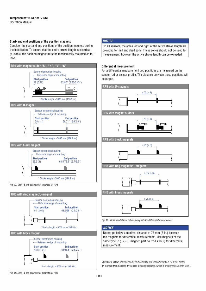
Start- and end positions of the position magnetsConsider the start and end positions of the position magnets during the installation. To ensure that the entire stroke length is electrical-ly usable, the position magnet must be mechanically mounted as fol-lows.
Fig. 17: Start- & end positions of magnets for RP5
Fig. 18: Start- & end positions of magnets for RH5
Controlling design dimensions are in millimeters and measurements in ( ) are in inches
NOTICE
On all sensors, the areas left and right of the active stroke length are provided for null and dead zone. These zones should not be used for measurement, however the active stroke length can be exceeded.
RP5 with magnet slider “S”, “N”, “V”, “G”
Sensor electronics housingReference edge of mounting
Start position12 (0.47)
End position82/87* (3.23/3.43*)
* Stroke length > 5000 mm (196.9 in.)
RP5 with U-magnet
Reference edge of mountingSensor electronics housing
Start position28 (1.1)
End position66/71* (2.6/2.8*)
* Stroke length > 5000 mm (196.9 in.)
RP5 with block magnet
Reference edge of mountingSensor electronics housing
* Stroke length > 5000 mm (196.9 in.)
End position68.5/73.5* (2.7/2.9*)
Start position25.5 (1)
RH5 with ring magnet/U-magnet
Sensor electronics housingReference edge of mounting
Start position51 (2.01)
End position63.5/66* (2.5/2.6*)
* Stroke length > 5000 mm (196.9 in.)
RH5 with block magnet
Sensor electronics housingReference edge of mounting
Start position48.5 (1.91)
End position66/68.5* (2.6/2.7*)
* Stroke length > 5000 mm (196.9 in.)
Differential measurementFor a differential measurement two positions are measured on the sensor rod or sensor profile. The distance between these positions will be output.
RP5 with U-magnets
≥ 75 (≥ 3)
RP5 with magnet sliders
≥ 75 (≥ 3)
RP5 with block magnets
≥ 75 (≥ 3)
RH5 with ring magnets/U-magnets
≥ 75 (≥ 3)
RH5 with block magnets
≥ 75 (≥ 3)
Fig. 19: Minimum distance between magnets for differential measurement
NOTICE
Do not go below a minimal distance of 75 mm (3 in.) between the magnets for differential measurement 3. Use magnets of the same type (e.g. 2 × U-magnet, part no. 251 416-2) for differential measurement.
3/ Contact MTS Sensors if you need a magnet distance, which is smaller than 75 mm (3 in.).

Temposonics® R-Series V SSIOperation Manual
I 17 I
4.5 Alignment of the magnet with the option “Internal lineariza-tion”
The internal linearization offers improved linearity of the sensor. The option must be specified in the order code of the sensor. The internal linearization is set for the sensor during production.A sensor with internal linearization is delivered with the magnet withwhich the sensor was aligned during production. In order to achievethe best possible result, MTS Sensors recommends to operate thesensor with the supplied magnet.
For the internal linearization, the following magnets can be used:• Ring magnet OD33 (part no. 253 620), only for RH5• U-magnet OD33 (part no. 254 226)• Ring magnet OD25.4 (part no. 253 621), only for RH5• Magnet slider S (part no. 252 182), only for RP5• Magnet slider N (part no. 252 183), only for RP5• Magnet slider V (part no. 252 184), only for RP5• Magnet slider G (part no. 253 421), only for RP5
The ring magnet and U-magnet will be marked for the internal linear-ization. During the installation, the magnets have to be alignedto the sensor electronic housing, see Fig. 20, Fig. 21 and Fig. 22.
For RH5 SSI sensors with ring magnet applies:• Install the magnet until the marking on the magnet points to the
sensor electronics housing.• The marking on the magnet points to the same direction as the
screw in the lid of the sensor electronics housing, which is located right of the status LED.
Fig. 20: Alignment of ring magnet for RH5 SSI with internal linearization
Marking
Elongated status LED
For RP5 SSI sensors with U-magnet applies:• Install the magnet until the marking on the magnet points to the
sensor electronics housing.• The marking on the magnet points to the same direction as the
screw in the lid of the sensor electronics housing, which is located right of the status LED.
Fig. 21: Magnet alignment of U-magnet for RP5 SSI with internal linearization
Marking
Elongated status LED
NOTICEThe generated linearization might deviate from the linearity toleranc-es regarding different environmental conditions. In addition, the use of a different position magnet or more position magnets may cause differences.
Fig. 22: Magnet alignment of magnet slider for RP5 SSI with internal linearization
For RP5 SSI sensors with magnet slider applies:• 1 Install the magnet sliders “S”, “N” and “G” until the additional
hole in the magnet points towards the sensor electronics housing.
• 2 Install the magnet slider “V” until the joint points to the end of the profile.
The internal linearization of the sensor is carried out under the following conditions:• Supply voltage +24 VDC ±0.5• Operating time > 30 min• No shock and no vibration• Eccentricity of the position magnet to central axis of the sensor
< 0.1 mm
1
2
Additional borehole
Joint

Temposonics® R-Series V SSIOperation Manual
I 18 I
Fig. 23: Replacement of the base unit (e.g. RH5 sensor), part 1
Base unit
Sensor electronics housing
Tube with inner sensor element
1. Loosen the screws.
3 × socket head screwM4 (A/F 2.5)
2. Pull out the base unit.
4.6 Replacement of base unit
The base unit of the sensor model RH5 (RH5-B) is replaceable as shown in Fig. 23 and Fig. 24 for the sensor designs »M«, »S« and »T«. The sensor can be replaced without interrupting the hydraulic cir-cuit.
3. Insert the new base unit. Install the ground lug on a screw. Tighten the screws.
Fastening torque 1.4 Nm
Fig. 24: Replacement of the base unit (e.g. RH5 sensor), part 2
NOTICE• If the R-Series V replaces a predecessor model of the R-Series,
the plastic tube in the sensor rod must be removed.• When replacing the base unit, make sure that no humidity enters
the sensor tube. This may damage the sensor.• Secure the base unit screws, e.g. using Loctite 243, before
re-installing.

Temposonics® R-Series V SSIOperation Manual
I 19 I
4.7 Electrical connection
Placement of installation and cabling have decisive influence on the sensor‘s electromagnetic compatibility (EMC). Hence correct installation of this active electronic system and the EMC of the entire system must be ensured by using suitable metal connectors, shielded cables and grounding. Overvoltages or faulty connections can damage its electronics despite protection against wrong polarity.
Instructions for connection• Use low-resistant twisted pair and shielded cables. Connect
the shield to ground externally via the control system equipment.• Keep control and signal cables separate from power cables and
sufficiently far away from motor cables, frequency inverters, valve lines, relays, etc..
• Use only connectors with metal housing and connect the shielding to the connector housing.
• Keep the connection surface at both shielding ends as large as possible. Connect the cable clamps to function as a ground.
• Keep all non-shielded leads as short as possible.• Keep the earth connection as short as possible with a large
cross section. Avoid ground loops.• With potential differences between machine and electronics earth
connections, no compensating currents are allowed to flow across the cable shielding. Recommendation: Install potential compensating leads with large cross section, or use cables with separate double shielding, and connect only one end of the shield.
• Use only stabilized power supplies in compliance with the specified electrical ratings.
Grounding of profile and rod sensorsConnect the sensor electronics housing to machine ground. Ground sensor types RP5 and RH5 via ground lug as shown in Fig. 25. In ad-dition you can ground the sensor type RH5 via thread.
Connector wiringConnect the sensor directly to the control system, indicator or other evaluating systems as follows:
Fig. 25: Grounding via ground lug (e.g. RH5)
Fig. 26: Location of connection (example connector output)
Fig. 27: Connector wiring D70
Fig. 28: Connector wiring cable output
NOTICE 1. Do not mount the sensors in the area of strong magnetic or
electric noise fields. 2. Never connect/disconnect the sensor when voltage is applied.
M16 connector
HXX / PXX / RXX / TXX
Signal + power supply
Cable Color Function
GY Data (−)
PK Data (+)
YE Clock (+)
GN Clock (−)
BN +12…30 VDC (±20 %)
WH DC Ground (0 V)
For cable type TXX, the extra red & blue wires are not used.
D70
Signal + power supply
M16 male connector Pin Function
142
63
5
7
View on sensor
1 Data (−)
2 Data (+)
3 Clock (+)
4 Clock (−)
5 +12…30 VDC (±20 %)
6 DC Ground (0 V)
7 Not connected

Temposonics® R-Series V SSIOperation Manual
I 20 I
4.8 Frequently ordered accessories for sensor model RP5 – Additional options available in our Accessories Guide 551 444
Position magnets
M5
20(0.79)
43(1.69)
14(0.55)
17.2
(0.6
7)
40 (1.57)
18°
25.3
(1)
40 (1.57)
18°
57 (2.24) 14 (0.55)
25.3
(1)
8.2
(0.3
2)49 (1.93)
M5 17.2
(0.6
7)
24(0.94)
18°
20(0.79)
43(1.69)
40 (1.57)
M5
25.3
(1) 18
°
40 (1.57)
25.3
(1)
20(0.79)
42(1.65)
15.2(0.6)
16.6
(0.6
3)
M5
Magnet slider S, joint at topPart no. 252 182
Magnet slider V, joint at frontPart no. 252 184
Magnet slider Nlonger ball-joint arm Part no. 252 183
Magnet slider G, backlash freePart no. 253 421
Material: GRP, magnet hard ferriteWeight: Approx. 35 gOperating temperature: −40…+85 °C (−40…+185 °F)
Material: GRP, magnet hard ferriteWeight: Approx. 35 gOperating temperature: −40…+85 °C (−40…+185 °F)
Material: GRP, magnet hard ferriteWeight: Approx. 35 gOperating temperature:−40…+85 °C (−40…+185 °F)
Material: GRP, magnet hard ferriteWeight: Approx. 25 gOperating temperature:−40…+85 °C (−40…+185 °F)
Position magnets Mounting accessories
Ø 32.8(Ø 1.29)
Ø 23.8(Ø 0.94)
Ø 13.5(Ø 0.53)
Ø 4.3(Ø 0.17)
60°
140°
3 (0.1
2)
7.9(0.31)
19.5 (0.77)
1.5
(0.0
6)
33 (1.3)
14(0.55)
20.5
(0.8
1)
14.9
(0.5
9)
8 ± 2 (0.31 ± 0.08)Distance to sensor element
Ø 4.3(Ø 0.17)
4 holesØ 5.3 (Ø 0.21) 28 (1.1) 9 (0.35)
50 (1.97)
2 (0
.08) 68 (2.68)
9.5
(0.3
7)Mounting clamp width:
14.6 (0.57)
4(0.16)
11.5(0.45)
4.5(1.8)
8(0.31)
M5 thread
U-magnet OD33Part no. 251 416-2
Block magnet LPart no. 403 448
Mounting clampPart no. 400 802
T-nutPart no. 401 602
Material: PA ferrite GF20Weight: Approx. 11 gSurface pressure: Max. 40 N/mm2
Fastening torque for M4 screws: 1 NmOperating temperature: −40…+105 °C (−40…+221 °F)
Material: Plastic carrier with hard ferrite magnetWeight: Approx. 20 gFastening torque for M4 screws: 1 NmOperating temperature: −40…+75 °C (−40…+167 °F)
This magnet may infl uence the sensor performance specifi cations for some applications.
Material: Stainless steel (AISI 304) Fastening torque for M5 screw: 4.5 Nm
Controlling design dimensions are in millimeters and measurements in ( ) are in inches
Marked version for sensors with inter-nal linearization: Part no. 254 226
Temposonics® R-Series V SSIOperation Manual
I 21 I
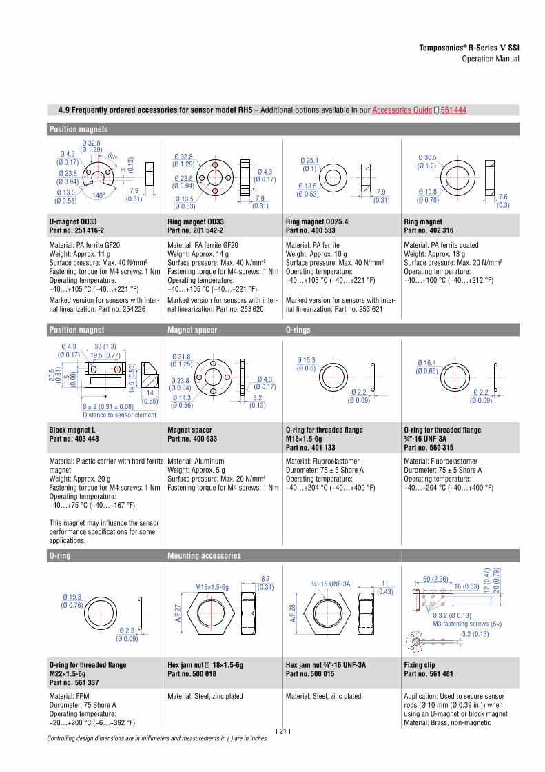
4.9 Frequently ordered accessories for sensor model RH5
Marked version for sensors with inter-nal linearization: Part no. 254 226
Marked version for sensors with inter-nal linearization: Part no. 253 620
Marked version for sensors with inter-nal linearization: Part no. 253 621
Position magnets
Ø 32.8(Ø 1.29)
Ø 23.8(Ø 0.94)
Ø 13.5(Ø 0.53)
Ø 4.3(Ø 0.17)
60°
140°
3 (0.1
2)
7.9(0.31)
Ø 32.8(Ø 1.29)
Ø 23.8(Ø 0.94)
Ø 13.5(Ø 0.53)
Ø 4.3(Ø 0.17)
7.9(0.31)
Ø 25.4(Ø 1)
Ø 13.5(Ø 0.53) 7.9
(0.31)Ø 19.8
(Ø 0.78)
Ø 30.5(Ø 1.2)
7.6(0.3)
U-magnet OD33Part no. 251 416-2
Ring magnet OD33Part no. 201 542-2
Ring magnet OD25.4Part no. 400 533
Ring magnetPart no. 402 316
Material: PA ferrite GF20Weight: Approx. 11 gSurface pressure: Max. 40 N/mm2
Fastening torque for M4 screws: 1 NmOperating temperature: −40…+105 °C (−40…+221 °F)
Material: PA ferrite GF20Weight: Approx. 14 gSurface pressure: Max. 40 N/mm2
Fastening torque for M4 screws: 1 NmOperating temperature: −40…+105 °C (−40…+221 °F)
Material: PA ferriteWeight: Approx. 10 gSurface pressure: Max. 40 N/mm2
Operating temperature: −40…+105 °C (−40…+221 °F)
Material: PA ferrite coatedWeight: Approx. 13 gSurface pressure: Max. 20 N/mm2
Operating temperature: −40…+100 °C (−40…+212 °F)
Position magnet Magnet spacer O-rings
19.5 (0.77)
1.5
(0.0
6)
33 (1.3)
14(0.55)
20.5
(0.8
1)
14.9
(0.5
9)
8 ± 2 (0.31 ± 0.08)Distance to sensor element
Ø 4.3(Ø 0.17)
Ø 14.3(Ø 0.56)
Ø 23.8(Ø 0.94)
Ø 31.8(Ø 1.25)
Ø 4.3(Ø 0.17)
3.2(0.13)
Ø 15.3(Ø 0.6)
Ø 2.2(Ø 0.09)
Ø 16.4(Ø 0.65)
Ø 2.2(Ø 0.09)
Block magnet LPart no. 403 448
Magnet spacerPart no. 400 633
O-ring for threaded fl ange M18×1.5-6gPart no. 401 133
O-ring for threaded fl ange ¾"-16 UNF-3APart no. 560 315
Material: Plastic carrier with hard ferrite magnetWeight: Approx. 20 gFastening torque for M4 screws: 1 NmOperating temperature: −40…+75 °C (−40…+167 °F)
This magnet may infl uence the sensor performance specifi cations for some applications.
Material: Aluminum Weight: Approx. 5 gSurface pressure: Max. 20 N/mm2
Fastening torque for M4 screws: 1 Nm
Material: Fluoroelastomer Durometer: 75 ± 5 Shore AOperating temperature:−40…+204 °C (−40…+400 °F)
Material: Fluoroelastomer Durometer: 75 ± 5 Shore AOperating temperature:−40…+204 °C (−40…+400 °F)
O-ring Mounting accessories
Ø 19.3(Ø 0.76)
Ø 2.2(Ø 0.09)
M18×1.5-6g
A/F
27
8.7(0.34) ¾"-16 UNF-3A
A/F
28
11(0.43) 20
(0.7
9)
60 (2.36)16 (0.63)
12 (0
.47)
3.2 (0.13)
Ø 3.2 (Ø 0.13)M3 fastening screws (6×)
O-ring for threaded fl ange M22×1.5-6gPart no. 561 337
Hex jam nut M18×1.5-6gPart no. 500 018
Hex jam nut ¾"-16 UNF-3APart no. 500 015
Fixing clipPart no. 561 481
Material: FPMDurometer: 75 Shore AOperating temperature:−20…+200 °C (−6…+392 °F)
Material: Steel, zinc plated Material: Steel, zinc plated Application: Used to secure sensor rods (Ø 10 mm (Ø 0.39 in.)) when using an U-magnet or block magnetMaterial: Brass, non-magnetic
Controlling design dimensions are in millimeters and measurements in ( ) are in inches
– Additional options available in our Accessories Guide 551 444
Controlling design dimensions are in millimeters and measurements in ( ) are in inches
Temposonics® R-Series V SSIOperation Manual
I 22 I
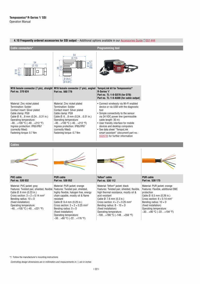
4.10 Frequently ordered accessories for SSI output – Additional options available in our Accessories Guide 551 444
Cable connectors* Programming tool
54(2.13)
Ø 18
(Ø 0
.71)
54(2.13)
38 (1.5
)
Ø 20.5(Ø 0.81)
Ø 18
(Ø 0
.71)
M16 female connector (7 pin), straightPart no. 370 624
M16 female connector (7 pin), angledPart no. 560 779
TempoLink kit for Temposonics® R-Series VPart no. TL-1-0-SD70 (for D70)Part no. TL-1-0-AS00 (for cable output)
Material: Zinc nickel platedTermination: SolderContact insert: Silver platedCable clamp: PG9Cable Ø: 6…8 mm (0.24…0.31 in.) Operating temperature: −40…+100 °C (−40…+212 °F) Ingress protection: IP65/IP67 (correctly fi tted)Fastening torque: 0.7 Nm
Material: Zinc nickel platedTermination: SolderContact insert: Silver platedCable clamp: PG9Cable Ø: 6…8 mm (0.24…0.31 in.) Operating temperature: −40…+100 °C (−40…+212 °F) Ingress protection: IP65/IP67 (correctly fi tted)Fastening torque: 0.7 Nm
• Connect wirelessly via Wi-Fi enabled device or via USB with the diagnostic tool
• Simple connectivity to the sensor via 24 VDC power line (permissible cable length: 30 m)
• User friendly interface for mobile devices and desktop computers
• See data sheet “TempoLink smart assistant” (document part no.: 552070) for further information
Cables
PVC cablePart no. 530 032
PUR cablePart no. 530 052
Tefl on® cablePart no. 530 112
PUR cablePart no. 530 175
Material: PVC jacket; grayFeatures: Twisted pair, shielded, fl exibleCable Ø: 6 mm (0.23 in.)Cross section: 3 × 2 × 0.14 mm2
Bending radius: 10 × D (fi xed installation)Operating temperature: −40…+105 °C (−40…+221 °F)
Material: PUR jacket; orangeFeatures: Twisted pair, shielded, highly fl exible, halogen free, energy chain capable, mostly oil & fl ame resistantCable Ø: 6.4 mm (0.25 in.)Cross section: 3 × 2 × 0.25 mm2
Bending radius: 5 × D (fi xed installation)Operating temperature: −30…+80 °C (−22…+176 °F)
Material: Tefl on® jacket; blackFeatures: Twisted pair, shielded, fl exible, high thermal resistance, mostly oil & acid resistantCable Ø: 7.6 mm (0.3 in.)Cross section: 4 × 2 × 0.25 mm²Bending radius: 8 – 10 × D (fi xed installation)Operating temperature: −100…+180 °C (−148…+356 °F)
Material: PUR jacket; orangeFeatures: Flexible, additional EMC protectionCable Ø: 6.5 mm (0.26 in.)Cross section: 6 × 0.14 mm2
Bending radius: 10 × D (fi xed installation)Operating temperature: −30…+90 °C (−22…+194 °F)
*/ Follow the manufacturer‘s mounting instructions
Controlling design dimensions are in millimeters and measurements in ( ) are in inches

Temposonics® R-Series V SSIOperation Manual
I 23 I
5. Commissioning
5.1 Introduction
SSIThe synchronous-serial interface (SSI) is a digital interface that en-ables serial transmission. Data is transmitted from the device to the connected control system synchronously to a clock rate specified by the control system. The interface of Temposonics® position sensors corresponds to SSI industry standard for absolute encoders. Its dis-placement value is encoded in a 24/25/26 bit binary or gray format and transmitted as a differential signal in SSI standard (RS-485/RS-422) – independent of data width of the code (resolu-tion). The absolute, parallel position data is continually updated by the sensor and converted by the shift-register into a serial bit stream. De-pendent on the baud rate chosen in the control system the following cable lengths are possible:
Logic diagram Sensor ControllerClock (+)
Clock (−)Optocoupler
Driver
Data (+)
Data (−)+24 VDC
0 V
ASIC
for p
aral
lel a
nd
abso
lute
pos
ition
dat
a
Mic
ropr
oces
sor s
yste
mpo
sitio
n va
lue
= 24
/25/
26 b
itbi
nary
or g
ray
Shift
regi
ster
para
llel s
eria
l con
verte
r
Sensor input100 Ω 7 mA
Clock (+)
100 Ω
LED
100 Ω
Clock (−)100 ΩOptocoupler
1.6 V
1 nF
1 nF
Cable length < 3 m < 50 m < 100 m < 200 m < 400 m
Baud rate 1 MBd < 400 kBd < 300 kBd < 200 kBd < 100 kBd
Clock T Standardone shot
n * T
MSB: Bit n Bit n - 1 Bit 3
Clock
Data
High
Low
High
LowLSB: Bit 1Bit 2
1 2 3 4 5 6
The data is transferred serially at SSI, whereby the control system de-termines the time of the polling. During data transmission, the proce-dure described below is carried out (Fig. 32):
1. In the idle state, when no data is transmitted, the data line and the clock line are at high level. 1
2. The current position data is frozen in the shift register with the first falling clock edge. It is no longer possible to update the position data in this cycle. 2
3. The bit is applied at the following rising edge. 3
4. With the following falling edge, the transmission of the data begins with the Most Significant Bit (MSB). 4
5. This is repeated for each next lower bit until the Last Significant Bit (LSB) is transmitted.
6. The standard one shot starts after the last falling clock edge 5 . After the transmission of the LSB, the data line remains on the low level and the clock line on the high level until the end of the standard one shot. Then the sensor is ready for the transmission of a new data 6 .
Fig. 29: Cable lengths and related baud rates
Fig. 30: Schematic connection
Fig. 31: Input wiring clock (+)/clock (−)
Fig. 32: Timing diagram

Temposonics® R-Series V SSIOperation Manual
I 24 I
5.2 LED status
The LED on the sensor visualizes the current sensor status. In normal function the LED is continuously green. In other cases the color of the LED changes in the time slot of 0.5 seconds as shown in Fig. 33.
R-Series V SSI LED statusStatus LED
Timeslot 1
Timeslot 2
Timeslot 3
Timeslot 4 Information
GN GN GN GN Normal functionRD + GN
RD + GN
RD + GN
RD + GN Magnet status error
BU + GN
BU + GN
BU + GN
BU + GN Sync status error
RD Off RD Off Power supply error
BU Off BU Off Command Mode
GN RD BU Off Extra magnet
GN Off GN Off Cycle timeout
GN BU RD Off Confi guration error
BU GN RD Off Storage error
BU RD GN Off Internal error
RD BU GN Off Signal error
RD GN BU Off Position error
1 × time slot = 0.5 seconds
Fig. 33: LED status
Fig. 34: Error conditions and troubleshooting
Error condition Description Troubleshooting
Magnet status error
Sensor registers less position magnets than set
Ensure that the number of position magnets on the sensor matches the set number.
Sync status error
Sensor cannot syn-chronize to the exter-nal clock of the control system
Adjust the parameter “Jit-ter Window”.Reduce the clock rate of the polling cycle at the control system.Ensure that the control system operates in syn-chronous mode.
Power supply error
Power supply of the sensor is out of the al-lowable range
Set the power supply for the sensor to the allowable range.
Extra magnet Sensor registers more position magnets than set
Ensure that the number of position magnets on the sensor matches the set number.
Cycle timeout In synchronous mode, the sensor does not re-ceive the clock for the polling cycle
Ensure that the clock of the control system arrives at the sensor. Ensure that the control system oper-ates in synchronous mode.
Configuration error
Invalid configuration of the sensor
Check the configuration of the sensor.Contact MTS Sensors.
Storage error Error in internal data storage
Contact MTS Sensors.
Internal error Internal error of the sensor
Contact MTS Sensors.
Signal error Internal signal error Contact MTS Sensors.
Position error Error in position mea-surement
Contact MTS Sensors.
Fig. 34 describes error conditions that are output via the LEDs and troubleshooting.
NOTICE
Observe during commissioning 1. Before initial switch-on, check carefully if the sensor has
been connected correctly. 2. Position the magnet in the measuring range of the sensor
during first commissioning and after replacement of the magnet.
3. Ensure that the sensor control system cannot react in an uncontrolled way when switching on.
4. Ensure that the sensor is ready and in operation mode after switching on. The status LED lights permanently green.
5. Check the preset span start and end values of the measuring range (see chapter 4.4) and correct them via the TempoLink smart assistant, if necessary.

Temposonics® R-Series V SSIOperation Manual
I 25 I
OUTPUT INPUT
SENSOR 24V DC
2. Connection to a sensor with cable output Connect the pig-tails of the sensor cable to the terminal clamps of the adapter cable according to the connector wiring in Fig. 37 (Fig. 38).
5.3 Programming and configuration
5.3.1 Connection of TempoLink smart assistant to R-Series V sensor
The TempoLink smart assistant can be connected to all R-Series V sensors. The adapter cable connects the TempoLink smart assistant to a R-Series V sensor. If the sensor is connected to a control system, disconnect the sensor from that control system before connecting the TempoLink smart assistant to the sensor. Connect the barrel connector of the adapter cable to the connection point labeled “OUTPUT SENSOR” on the TempoLink smart assistant (Fig. 35).
NOTICE
• When disconnecting the power supply of the sensor, possibly error messages occur at the connected control system.
• Do not exceed the maximum cable length between TempoLink smart assistant and R-Series V sensor of 30 m (99 ft.).
Fig. 35: Connection of adapter cable to TempoLink smart assistant
1. Connection to a sensor with connector output Connect the other end of the adapter cable to the R-Series V. The sensor is powered by the TempoLink smart assistant (Fig. 36).
Fig. 36: Connection of adapter cable to R-Series V sensor with connector output
Fig. 37: Connection of adapter cable to sensor cable
Fig. 38: Connection of adapter cable to R-Series V sensor with cable output
Color sensor cable Color adapter cable Function
GY GY –
PK PK –
YE YE –
GN GN –
BN BN + 24 VDC
WH WH DC Ground (0 V)

Temposonics® R-Series V SSIOperation Manual
I 26 I
5.3.2 Connection of TempoLink smart assistant to power supply
Connect the barrel connector of the power supply to the connection point labeled “INPUT 24 VDC” on the TempoLink smart assistant (Fig. 39).
OUTPUT INPUT
SENSOR 24V DC
2. Connection via the cable with barrel connector and pig-tail Connect the cable to a power supply according to the connector wiring in Fig. 41 (Fig. 42).
There are two ways to connect the TempoLink smart assistant to a power supply:
1. Connection via the plug-in power supply with plug adapters Attach the plug attachment suitable for your country to the plug. Insert the plug into the outlet (Fig. 40).
Fig. 39: Connection of power supply to the TempoLink smart assistant
Fig. 40: Connection of the plug-in power supply to the outlet
Fig. 41: Connector wiring cable
Fig. 42: Connection of cable with barrel connector and pig-tails
Connection to power supply
Cable Function
RD +24 VDC
BK DC Ground (0 V)

Temposonics® R-Series V SSIOperation Manual
I 27 I
5.3.3 Connection of TempoLink smart assistant to smartphone, tablet or computer
Connect to a smartphone, tablet or computer to display the graphical user interface of the TempoLink smart assistant.
Connecting a Wi-Fi enabled device to the integrated Wi-Fi access point 4
Activate Wi-Fi on the device and choose the network “TempoLink_xxxx” (xxxx indicates the last four digits of the serial number). The access to the Wi-Fi network is password protected. The default password is the serial number printed on the label on the bot-tom of the TempoLink smart assistant.
4/ The integrated Wi-Fi access point does not provide internet access.
NOTICEIf you are using a mobile device, ensure cellular data is off. Depend-ing on your operation system, message can appear, that there is no internet access. TempoLink smart assistant does not need internet access. Connecting to the user interface may take longer if Wi-Fi and cellular data are active.
Connecting a computer via USB connectionThe TempoLink smart assistant can also be connected via USB. If the computer is Wi-Fi enabled deactivate Wi-Fi on the computer before setting up the USB connection.
1. Connect the USB cable with the micro USB connector to the port labeled “USB” on the TempoLink smart assistant (Fig. 44).
2. Next, connect the USB type-A connector to a free USB port of the computer. The USB connection simulates a network card. In the folder “network connections” on the computer the connection is shown as “IP-over-USB” or “Remote NDIS”.
USB connector
NOTICEOnly one device can be connected to the TempoLink smart assistant at a time in order to display the graphical user interface.
NOTICEDisable all Wi-Fi and LAN connections before connecting TempoLink smart assistant via USB. Connecting to the user interface may take longer if Wi-Fi and LAN connections are active. Should the websitedo not build up, it may be useful to press CTRL + F5 to delete cached text and images from prior to launching the http://tempolink.local website.
5.3.4 Establishing a connection via browser
After the connection via Wi-Fi or USB is established, open the browser on your mobile device or computer and go to the website-URL: http://tempolink.local
Connection statusGreen Information
ON Connection to sensor is establishedRed Information
ON Connection to sensor is not establishedBlue Information
ON Sensor in command mode
Fig. 43: Choose the network “TempoLink_xxxx” in the Wi-Fi settings of the Wi-Fi-enabled device
Fig. 44: USB port on the TempoLink smart assistant
Fig. 45: Main menu of the graphical user interface
Fig. 46: Connection status

Temposonics® R-Series V SSIOperation Manual
I 28 I
Fig. 50: Configuration of SSI parameters
Measuring Direction: Setting the measuring direction for positionmeasurement.• Forward• Reverse
Measurement Function: Setting the function of the measurement.• Position• Velocity• Differential
NOTICERead the TempoLink smart assistant operation manual (document part number: 551986) for more information.
5.3.5 Graphical user interface
Click the menu symbol in the top left to get to the main menu of the graphical user interface (GUI) (Fig. 47):
TempoLink: Includes information about the TempoLink smart assistant.
Status: Includes information about the sensor status.
Sensor Info: Includes information about the connected sensor.
Parameters: Includes information about the operational settings of the connected sensor (Fig. 48).
To change parameters or to reset the sensor to factory settings, the command mode must be started. In command mode, the sensor does not output a position value. By clicking the button “ENTER COMMAND” MODE the “Enter Command Mode” window opens. After reading the information, enter the word COMMAND and confirm by clicking “OK” (Fig. 49).
Fig. 47: Main menu of the graphical user interface
Fig. 48: SSI parameters
Fig. 49: Starting the command mode to change parameters of the connected sensor
After entering the command mode the connection icon on the topright will turn from green to blue. The status LED of the sensor also flashes blue. A pencil icon will appear to the right of parameter val-ues. By clicking the pencil icon a new menu for configuring the param-eters will open. Change the parameter and confirm it by clicking the “SUBMIT” button (Fig. 50).

Temposonics® R-Series V SSIOperation Manual
I 29 I
Fig. 51: Exit the command mode
NOTICEChanges to the sensor parameters must also be set to the control system.Different parameter values on sensor and control system can lead tounpredictable behavior of the control system.
Interface: Includes information about the interface settings of theconnected sensor (Fig. 52).
Fig. 52: Configuration of SSI settings
To change interface settings, start the command mode (page 28).After entering the command mode a pencil icon will appear to theright of the setting values. By clicking the pencil icon a new menu forconfiguring the settings will open. Change the parameter and confirmit by clicking the “SUBMIT” button (Fig. 53).
Synchronization Mode: Setting the type of synchronization for theposition measurement.• Asynchronous• Synchronous mode 1• Synchronous mode 2• Synchronous mode 3
Resolution: Setting the resolution of the position measurement.
Linearization: Setting the internal linearization.• Enabled NOTICE “Enabled” can only be activated if the sensor was ordered with the option “internal linearization”.• Disabled
Filter Configuration: Setting of the filter for the output value.Filter Type: Setting the filter type.
• None: No filter (default value)• FIR (Finite Impulse Response Filter)• IIR (Infinite Impulse Response Filter)
Filter Window Size: Setting of position values for calculating the filter of the output value.
By clicking the button “FACTORY RESET” the sensor is reset tothe factory setting. After the parameters have been configured or the factory reset has been carried out, click the “EXIT COMMANDMODE” button. A new menu for exiting the command mode will open(Fig. 51). Click the “SAVE AND EXIT” button to exit the command mode and to transfer the changed parameters to the sensor. The sen-sor returns to the normal function and outputs the current position value. The connection icon on the top right will turn to green. The sta-tus LED of the sensor flashes green.
Fig. 53: Configuration of SSI settings
Data Format: Setting the SSI coding for the data transmission.
Data Length: Setting the bit width for the data transmission.
Temposonics® R-Series V SSIOperation Manual
I 30 I
6. Maintenance and troubleshooting
6.1 Error conditions, troubleshooting
See chapter “5. Commissioning” on page 23.
6.2 Maintenance
The sensor is maintenance-free.
6.3 Repair
Repairs of the sensor may be performed only by MTS Sensors or a repair facility explicitly authorized by MTS Sensors. For return see chapter “2.6 Return” on page 4.
NOTICEChanges to the sensor parameters must also be set to the control system.Different parameter values on sensor and control systems can lead to unpredictable behavior of the control system.
Jitter Window: The jitter specifies the time interval between thestart of measuring and the SSI clock, which is given by the PLC(for synchronous mode). Values between 0…255 μs can be setfor this parameter (default value: 50 μs). A larger value extends thecycle time of the sensor.
Monoflop Time: Break between two consecutive bar sequences (Fig. 32). Values between 16…25 µs can be set for this parameter (default value: 16 µs).
Error Values: Setting the values which are transmitted in case of afailure.
Power Failure: Setting the time from when a power failure is output.
Error Counter: Setting the number how often in the case of a failure(1…255 times) the old measurement value will be repeated, beforethe error value will be displayed.
After the settings have been configured, click the “EXIT COMMANDMODE” button. A new menu for exiting the command mode will open.Click the “SAVE AND EXIT” button to exit the command mode andto transfer the changed settings to the sensor. The sensor returnsto the normal function and outputs the current position value. Theconnection icon on the top right will turn to green. The status LED of the sensor flashes green.
6.4 List of spare parts
No spare parts are available for this sensor. 6.5 Transport and storage
The conditions of transport and storage of the sensor match the oper-ating conditions mentioned in this document.
7. Removal from service/dismantling
The product contains electronic components and must be disposed of in accordance with the local regulations.
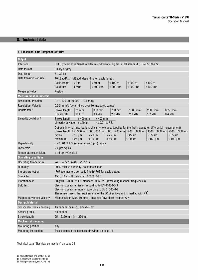
Temposonics® R-Series V SSIOperation Manual
I 31 I
Output
Interface SSI (Synchronous Serial Interface) – differential signal in SSI standard (RS-485/RS-422)
Data format Binary or gray
Data length 8…32 bitData transmission rate 70 kBaud 5…1 MBaud, depending on cable length:
Cable length < 3 m < 50 m < 100 m < 200 m < 400 mBaud rate 1 MBd < 400 kBd < 300 kBd < 200 kBd < 100 kBd
Measured value Position
Measurement parametersResolution: Position 0.1…100 µm (0.0001…0.1 mm)
Resolution: Velocity 0.001 mm/s (determined over 10 measured values)Update rate 6 Stroke length 25 mm 300 mm 750 mm 1000 mm 2000 mm 6350 mm
Update rate 10 kHz 3.4 kHz 2.7 kHz 2.1 kHz 1.2 kHz 0.4 kHzLinearity deviation 7 Stroke length ≤ 400 mm > 400 mm
Linearity deviation ≤ ±40 μm < ±0.01 % F.S.
Optional internal linearization: Linearity tolerance (applies for the first magnet for differential measurement)Stroke length 25...300 mm 300...600 mm 600...1200 mm 1200...3000 mm 3000...5000 mm 5000...6350 mmtypical ± 15 µm ± 20 µm ± 25 µm ± 45 µm ± 85 µm ± 95 µmmaximum ± 25 µm ± 30 µm ± 50 µm ± 90 µm ± 150 µm ± 190 µm
Repeatability < ±0.001 % F.S. (minimum ±2.5 μm) typical
Hysteresis < 4 µm typical
Temperature coefficient < 15 ppm/K typical
Operating conditionsOperating temperature −40…+85 °C (−40…+185 °F)
Humidity 90 % relative humidity, no condensation
Ingress protection IP67 (connectors correctly fitted)/IP68 for cable output
Shock test 150 g/11 ms, IEC standard 60068-2-27
Vibration test 30 g/10…2000 Hz, IEC standard 60068-2-6 (excluding resonant frequencies)EMC test Electromagnetic emission according to EN 61000-6-3
Electromagnetic immunity according to EN 61000-6-2The sensor meets the requirements of the EC directives and is marked with .
Magnet movement velocity Magnet slider: Max. 10 m/s; U-magnet: Any; block magnet: Any
Design/MaterialSensor electronics housing Aluminum (painted), zinc die cast
Sensor profile Aluminum
Stroke length 25…6350 mm (1…250 in.)
Mechanical mountingMounting position Any
Mounting instruction Please consult the technical drawings on page 11
8. Technical data
5/ With standard one shot of 16 μs 6/ Sensor with standard settings7/ With position magnet # 252 182
8.1 Technical data Temposonics® RP5
Technical data “Electrical connection” on page 32

Temposonics® R-Series V SSIOperation Manual
I 32 I
Electrical connectionConnection type 1 × M16 male connector (7 pin) or cable output
Operating voltage +12…30 VDC ±20 % (9.6…36 VDC)
Power consumption 1.2 W typical
Dielectric strength 500 VDC (DC ground to machine ground)
Polarity protection Up to −36 VDC
Overvoltage protection Up to 36 VDC

Temposonics® R-Series V SSIOperation Manual
I 33 I
OutputInterface SSI (Synchronous Serial Interface) – differential signal in SSI standard (RS-485/RS-422)
Data format Binary or gray
Data length 8…32 bitData transmission rate 70 kBaud 8…1 MBaud, depending on cable length:
Cable length < 3 m < 50 m < 100 m < 200 m < 400 mBaud rate 1 MBd < 400 kBd < 300 kBd < 200 kBd < 100 kBd
Measured value Position
Measurement parametersResolution: Position 0.1…100 µm (0.0001…0.1 mm)
Resolution: Velocity 0.001 mm/s (determined over 10 measured values)Update rate 9 Stroke length 25 mm 300 mm 750 mm 1000 mm 2000 mm 7620 mm
Update rate 10 kHz 3.4 kHz 2.7 kHz 2.1 kHz 1.2 kHz 0.3 kHzLinearity deviation 10 Stroke length ≤ 400 mm > 400 mm
Linearity deviation ≤ ±40 μm < ±0.01 % F.S.
Optional internal linearization: Linearity tolerance (applies for the first magnet for differential measurement)Stroke length 25...300 mm 300...600 mm 600...1200 mmtypical ± 15 µm ± 20 µm ± 25 µmmaximum ± 25 µm ± 30 µm ± 50 µm
Repeatability < ±0.001 % F.S. (minimum ±2.5 μm) typical
Hysteresis < 4 µm typical
Temperature coefficient < 15 ppm/K typical
Operating conditionsOperating temperature −40…+85 °C (−40…+185 °F)
Humidity 90 % relative humidity, no condensation
Ingress protection IP67 (connectors correctly fitted)/IP68 for cable outputShock test 150 g/11 ms, IEC standard 60068-2-27Vibration test 30 g/10…2000 Hz, IEC standard 60068-2-6 (excluding resonant frequencies)/
RH5-J: 15 g/10…2000 Hz, IEC standard 60068-2-6 (excluding resonant frequencies)EMC test Electromagnetic emission according to EN 61000-6-3
Electromagnetic immunity according to EN 61000-6-2The sensor meets the requirements of the EC directives and is marked with .
Operating pressure 350 bar (5,076 psi)/700 bar (10,153 psi) peak (at 10 × 1 min) for sensor rod/RH5-J: 800 bar (11,603 psi)
Magnet movement velocity Any
Design/MaterialSensor electronics housing Aluminum (painted), zinc die cast
Sensor flange Stainless steel 1.4305 (AISI 303)
Sensor rod Stainless steel 1.4306 (AISI 304L)/RH5-J: Stainless steel 1.4301 (AISI 304)
Stroke length 25…7620 mm (1…300 in.)/RH5-J: 25…5900 mm (1…232 in.)
Mechanical mountingMounting position Any
Mounting instruction Please consult the technical drawings on page 12 and page 13
8.2 Technical data Temposonics® RH5
8/ With standard one shot of 16 μs9/ Sensor with standard settings10/ With position magnet # 251 416-2
Technical data “Electrical connection” on page 34
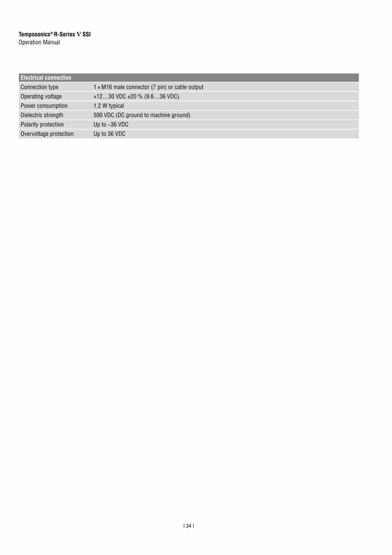
Temposonics® R-Series V SSIOperation Manual
I 34 I
MTS Sensors order number: ________________________________
Serial number(s): _________________________________________
Sensor type(s): __________________________________________
Sensor length(s): ________________________________________
The sensor has been in contact with the following materials:
In the event of suspected penetration of substances into the sensor, consult MTS Sensors to determine measures to be taken before shipment.
Do not specify chemical formulas.Please include safety data sheets of the substances, if applicable.
Short description of malfunction:
Corporate information
Company: _______________________________________________
Address: _______________________________________________
_______________________________________________________
Contact partner
Name: _______________________________________________
Phone: _______________________________________________
E-mail: _______________________________________________
We hereby certify that the measuring equipment has been cleaned and neutralized. Equipment handling is safe. Personnel exposure to health risks during transport and repair is excluded.
DateSignatureStamp
Tel. + 49 - 23 51- 95 87 0Fax. + 49 - 23 51- 5 64 [email protected]
GERMANYMTS Sensor Technologie GmbH & Co.KG Auf dem Schüffel 9 58513 Lüdenscheid, Germany
USA MTS Systems CorporationSensors Division3001 Sheldon DriveCary, N.C. 27513, USA
Tel. +1 919 677-0100Fax +1 919 [email protected]
Safety declaration
Dear Customer,If you return one or several sensors for checking or repair, we need you to sign a safety declaration. The purpose of this declaration is to ensure that the returned items do not contain residues of harmful substances and/or that people handling these items will not be in danger.
MTS Sensors order number: ________________________________
Serial number(s): _________________________________________
Sensor type(s): __________________________________________
Sensor length(s): ________________________________________
The sensor has been in contact with the following materials:
In the event of suspected penetration of substances into the sensor, consult MTS Sensors to determine measures to be taken before shipment.
Do not specify chemical formulas.Please include safety data sheets of the substances, if applicable.
Short description of malfunction:
Corporate information
Company: _______________________________________________
Address: _______________________________________________
_______________________________________________________
Contact partner
Name: _______________________________________________
Phone: _______________________________________________
E-mail: _______________________________________________
We hereby certify that the measuring equipment has been cleaned and neutralized. Equipment handling is safe. Personnel exposure to health risks during transport and repair is excluded.
DateSignatureStamp
Tel. + 49 - 23 51- 95 87 0Fax. + 49 - 23 51- 5 64 [email protected]
GERMANYMTS Sensor Technologie GmbH & Co.KG Auf dem Schüffel 9 58513 Lüdenscheid, Germany
USA MTS Systems CorporationSensors Division3001 Sheldon DriveCary, N.C. 27513, USA
Tel. +1 919 677-0100Fax +1 919 [email protected]
Electrical connectionConnection type 1 × M16 male connector (7 pin) or cable output
Operating voltage +12…30 VDC ±20 % (9.6…36 VDC)
Power consumption 1.2 W typical
Dielectric strength 500 VDC (DC ground to machine ground)
Polarity protection Up to −36 VDC
Overvoltage protection Up to 36 VDC
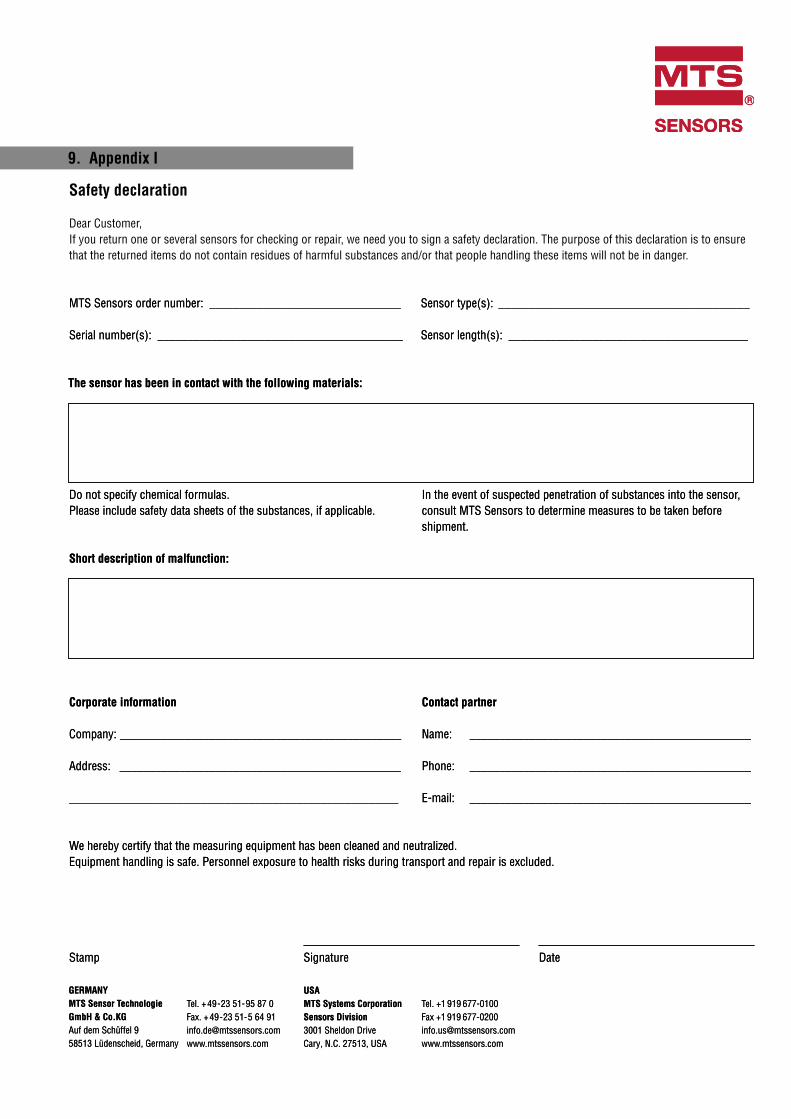
9. Appendix I
MTS Sensors order number: ________________________________
Serial number(s): _________________________________________
Sensor type(s): __________________________________________
Sensor length(s): ________________________________________
The sensor has been in contact with the following materials:
In the event of suspected penetration of substances into the sensor, consult MTS Sensors to determine measures to be taken before shipment.
Do not specify chemical formulas.Please include safety data sheets of the substances, if applicable.
Short description of malfunction:
Corporate information
Company: _______________________________________________
Address: _______________________________________________
_______________________________________________________
Contact partner
Name: _______________________________________________
Phone: _______________________________________________
E-mail: _______________________________________________
We hereby certify that the measuring equipment has been cleaned and neutralized. Equipment handling is safe. Personnel exposure to health risks during transport and repair is excluded.
DateSignatureStamp
Tel. + 49 - 23 51- 95 87 0Fax. + 49 - 23 51- 5 64 [email protected]
GERMANYMTS Sensor Technologie GmbH & Co.KG Auf dem Schüffel 9 58513 Lüdenscheid, Germany
USA MTS Systems CorporationSensors Division3001 Sheldon DriveCary, N.C. 27513, USA
Tel. +1 919 677-0100Fax +1 919 [email protected]
Safety declaration
Dear Customer,If you return one or several sensors for checking or repair, we need you to sign a safety declaration. The purpose of this declaration is to ensure that the returned items do not contain residues of harmful substances and/or that people handling these items will not be in danger.
MTS Sensors order number: ________________________________
Serial number(s): _________________________________________
Sensor type(s): __________________________________________
Sensor length(s): ________________________________________
The sensor has been in contact with the following materials:
In the event of suspected penetration of substances into the sensor, consult MTS Sensors to determine measures to be taken before shipment.
Do not specify chemical formulas.Please include safety data sheets of the substances, if applicable.
Short description of malfunction:
Corporate information
Company: _______________________________________________
Address: _______________________________________________
_______________________________________________________
Contact partner
Name: _______________________________________________
Phone: _______________________________________________
E-mail: _______________________________________________
We hereby certify that the measuring equipment has been cleaned and neutralized. Equipment handling is safe. Personnel exposure to health risks during transport and repair is excluded.
DateSignatureStamp
Tel. + 49 - 23 51- 95 87 0Fax. + 49 - 23 51- 5 64 [email protected]
GERMANYMTS Sensor Technologie GmbH & Co.KG Auf dem Schüffel 9 58513 Lüdenscheid, Germany
USA MTS Systems CorporationSensors Division3001 Sheldon DriveCary, N.C. 27513, USA
Tel. +1 919 677-0100Fax +1 919 [email protected]

Temposonics® R-Series V SSIOperation Manual
10. Appendix II
C Y L I N D E R P O R T D E T A I L S
NOTES:1. Dimensions and tolerances based on ANSI Y14.5-1982.2. MTS has extracted all pertinent information from
MS33649 to generate this document.3. PD must be square with surface B within 0.005 FIM
across 2.250 dia minimum.4. PD must be concentric with 2.250 dia within 0.030 FIM
and with 0.769 dia within 0.005 FIM.5. Surface texture ANSI B46.1-19786. Use O-ring MTS part number 560315 for correct sealing.7. The thread design shall have sufficient threads to meet
strength requirements of material used.8. Finish counter-bore shall be free from longitudinal and
spiral tool marks. Annular tool marks up to 32microinches maximum will be permissible.
2.250 in. Minimum dia.Specifies Surface B
120 0 30'
0.094 in. + 0.015- 0.000
See Detail C
3/4-16 UNF-2B ThreadSee Notes 3 And 4
32
in.
32 in.125 in.
- B -
1.105 in.Minimum
Full ThreadDepth
0.875 in. dia.+ 0.015- 0.000
0.769 in. dia.+ 0.015- 0.000
0.500 in.dia.
0.005 in. dia., FIMA
45 5
15 1
0.094 in. max.
0.008 in.0.004 in.
0.125 in.
0.125 in.
3/4-16 UNF-2B Thread
R
0.813 in. dia.0.002 in.
0.106 in.0.008 in.
A
0.008 A0.004 A
R0.015 in.max.
Pitchdia.
1.180 in.Recommended
MinimumSpotfaceDiameter
See Note 1
0.866 in. dia.Minimum
See Note 2
1.100 in.See Note 4
1.250 in.See Note 3See Note 4
0.500 in. dia. Ref.See Note 4
SAE - 8 Port Size
0.094 in. Ref.
See Note 8
0.030 in. 0.010 R
0.020 in. RMaximum
45 5
PORT DETA IL (PD) FOR RH5 -S :
PORT DETA IL (PD) FOR RH5 -T:
NOTES:1. If face of port is on a machined surface, dimensions
1.180 and 0.094 need not apply as long as R0.008/0.004is maintained to avoid damage to the O-ring duringinstallation.
2. Measure perpendicularity to A at this diameter.3. This dimension applies when tap drill cannot pass
through entire boss.4. This dimension does not conform to SAE J1926/1.
Detail C

Temposonics® R-Series V SSIOperation Manual
11. Glossary
A
AlarmThe alarm bit is set by the sensor if the sensor detects more magnets (extra magnet) or less magnets (magnet status error) than confi gured.Asynchronous modeIn asynchronous mode the position data is continuously updated inside the sensor as quickly as the sensor’s measurement cycle will allow, independent of the controller. The controller’s loop time will determine when the sensor’s most recent data is clocked out over the SSI interface. ( Synchronous mode)
D
Differential measurementFor differential measurement, the distance between the two position magnets is output as a value.
E
ExtrapolationThe native measurement cycle time of a sensor increases with thestroke length. With extrapolation, the sensor is able to report datafaster than the native cycle time, independent of the stroke length ofthe sensor. Without extrapolation, if data is requested faster than thenative cycle time, the last measured value is repeated.
F
FIR FilterThe FIR fi lter (Finite Impulse Response) is used to smooth themeasured position value before output. To determine the outputvalue, only input values corresponding to the window (fi lter windowsize) are used for fi lter calculation. The output value is calculatedfrom these input values in the form of a moving average value.( IIR Filter)
I
IIR FilterThe IIR fi lter (Infi nite Impulse Response) is used to smooth themeasured position value before output. To determine the outputvalue, the input values corresponding to the fi lter grade (fi lter win-dow size) are used for the fi lter calculation. The previous values are also taken into account when calculating the output value. ( FIR Filter)Internal LinearizationThe internal linearization offers an improved linearity for an overall higher accuracy of the position measurement. The internal lineariza-tion is set for the sensor during production.
M
Measuring directionWhen moving the position magnet, the position and velocity values increase in the measuring direction.• Forward: Values increasing from sensor electronics housing
to rod end/profi le end• Reverse: Values decreasing from sensor electronics housing
to rod end/profi le end
P
ParityThe parity bit is a check bit that is added to a bit string to detect transmission errors. There are even parity and odd parity. With even parity, the parity bit is set so that the total number of 1-bits in the bit string including the parity bit is even. In case of odd parity, the total number of 1-bits in the bit sequence including the parity bit is odd. Even parity is implemented in the R-Series V SSI.
S
Synchronous Serial Interface SSI (Synchronous Serial Interface) is a digital interface where the data is transferred serially.The interface of R-Series V SSI corre-sponds to SSI industry standard for absolute encoders. Its displace-ment value is encoded in a 24/25/26 bit binary or gray format and transmitted as a differential signal in SSI standard (RS-485/RS-422).Synchronous mode In synchronous mode the measurement and output of the sensor is matched to the data request cycle of the controller. The synchronous mode minimizes the time delay between measurement and output. The synchronous mode is required for sophisticated motion control applications. ( Asynchronous mode)• Synchronous mode 1
Using synchronous mode 1, the sensor determines the controller’s loop timing and when data is being requested. The sensor then determines when to start the next measurement cycle so that it will complete just in time to deliver the freshest data possible.
• Synchronous mode 2 If new position data is required faster than the sensor’s measurement cycle time, synchronous mode 2 provides extrapolated data values, calculated on the fl y. A measurement value will be calculated and output to the controller whenever the sensor has not yet completed the next measurement cycle.
• Synchronous mode 3Synchronous mode 3 provides an additional enhancement to the high speed update feature of synchronous mode 2. For this mode all measurements values which are output are calculated to fully compensate for the inherent lag time due to the sensor’s measurement cycle.
T
Temperature in the sensor electronics housingThe temperature in the sensor electronics housing is measured in °C. With this option, the transmitted data word has a length of 32 bits, with the highest 8 bits representing the temperature value, followed by 24 bits for the position value.

USA MTS Systems Corporation
Sensors DivisionAmerika & APAC Region
3001 Sheldon DriveCary, N.C. 27513Telefon: +1 919 677-0100E-Mail: [email protected]
DEUTSCHLANDMTS Sensor Technologie
GmbH & Co. KGEMEA Region & Indien
Auf dem Schüffel 958513 LüdenscheidTelefon: +49 2351 9587-0E-Mail: [email protected]
ITALIENZweigstelle
Telefon: +39 030 988 3819E-Mail: [email protected]
FRANKREICHZweigstelle
Telefon: +33 1 58 4390-28E-Mail: [email protected]
UKZweigstelle
Telefon: +44 79 44 15 03 00E-Mail: [email protected]
SKANDINAVIENZweigstelle
Telefon: + 46 70 29 91 281E-Mail: [email protected]
CHINAZweigstelle
Telefon: +86 21 2415 1000 / 2415 1001E-Mail: [email protected]
JAPANZweigstelle
Telefon: +81 3 6416 1063E-Mail: [email protected]
www.mtssensors.comMTS, Temposonics und Level Plus sind eingetragene Warenzeichen der MTS Systems Corporation in den USA. MTS Sensors und das MTS Sensors Logo sind Warenzeichen der MTS Systems Corporation in den USA. Diese Warenzeichen können auch in anderen Ländern geschützt sein. Alle anderen Warenzeichen sind im Besitz des jeweiligen Eigentümers. Copyright © 2020 MTS System Corporation. Keine Vergabe von Lizenzen an geistigem Eigentum. MTS behält sich vor, ohne Ankündigung die Informationen in diesem Dokument sowie das Produktdesign zu ändern sowie Produkte aus dem Verkauf zu nehmen. Typografi sche und grafi sche Fehler oder Auslassungen sind unbeabsichtigt. Alle Informationen ohne Gewähr. Auf der Website www.mtssensors.com erhalten Sie die aktuellen Produktinformationen.
Document Part Number: 552011 Revision B (EN) 12/2020