Operation Manual - PN 0011470001 D2 DPG · PDF filecode sn dpg iibarometer - model 14500 ®...
102
CODE SN DPG II BAROMETER - MODEL 14500 Operation Manual - PN 0011470001 D2 ® MENSOR CORPORATION 201 BARNES DRIVE SAN MARCOS, TEXAS 78666-5994 Phone: 512.396.4200 Fax: 512.396.1820 Web site: www.mensor.com
Transcript of Operation Manual - PN 0011470001 D2 DPG · PDF filecode sn dpg iibarometer - model 14500 ®...

CODE
SN
DPG II BAROMETER - MODEL 14500Operation Manual - PN 0011470001 D2®
MENSOR CORPORATION
201 BARNES DRIVE
SAN MARCOS, TEXAS 78666-5994
Phone: 512.396.4200
Fax: 512.396.1820
Web site: www.mensor.com

WARRANTY
All products manufactured by Mensor®
Corporation are warranted to be free ofdefects in workmanship and materials for a period of one year from the date ofshipment. No other express warranty is given, and no affirmation of Seller, bywords or actions, shall constitute a warranty. SELLER DISCLAIMS ANY IM-PLIED WARRANTIES OF MERCHANTABILITY OR FITNESS FOR ANY PAR-TICULAR PURPOSES WHATSOEVER. If any defect in workmanship or materialshould develop under conditions of normal use and service within the warrantyperiod, repairs will be made at no charge to the original purchaser, upon deliveryof the product(s) to the factory, shipping charges prepaid. If inspection by MensorCorporation or its authorized representative reveals that the product was dam-aged by accident, alteration, misuse, abuse, faulty installation or other causesbeyond the control of Mensor Corporation, this warranty does not apply. Thejudgment of Mensor Corporation will be final as to all matters concerningcondition of the product, the cause and nature of a defect, and the necessity ormanner of repair. Service, repairs or disassembly of the product in any manner,performed without specific factory permission, voids this warranty.
MENSOR CORPORATION MAKES NO WARRANTY OF ANY KIND WITH RE-GARD TO THIS MANUAL, INCLUDING, BUT NOT LIMITED TO, THE IMPLIEDWARRANTIES OF MERCHANTABILITY AND FITNESS FOR A PARTICULARPURPOSE. Mensor Corporation shall not be liable for errors contained hereinor for incidental or consequential damages in connection with the furnishing,performance, or use of this material.
ii 2/28/97 MENSOR CORP.

WARNINGS AND CAUTION NOTES
WARNING: NOT EXPLOSION PROOF! Installation of this instrument in anarea requiring devices rated as intrinsically safe is not recommended.
CAUTION: USE THE PROPER PRESSURE MEDIUM. USE ONLY CLEAN,
DRY NON-CORROSIVE GASES. THIS INSTRUMENT IS NOT DESIGNED
FOR OXYGEN USE.
CAUTION: AS WITH MOST SENSITIVE ELECTRONIC EQUIPMENT,
SWITCH THE POWER SWITCH OFF BEFORE CONNECTING OR DIS-
CONNECTING TO A POWER SOURCE TO PREVENT DATA LOSS
PLEASE NOTICE...
The product specifications and other information contained in this manual aresubject to change without notice.
Mensor Corporation has made a concerted effort to provide complete and currentinformation for the proper use of the equipment. If there are questions regardingthis manual or the proper use of the equipment, contact Mensor Corporation at:
TEL 1-512-396-4200 or 1-800-984-4200 (USA only)FAX 1-512-396-1820WEB SITE http://www.mensor.comE-MAIL [email protected]
CAUTION: ESD PROTECTION REQUIRED.The proper use of grounded work surfaces andpersonal wrist straps are required when cominginto contact with exposed circuits (printed circuitboards) to prevent static discharge damage tosensitive electronic components.
MENSOR CORP. 2/28/97 iii

PACKAGING FOR SHIPMENT
If the product must be shipped to a different location or returned to Mensor forany reason through a common carrier it must be packaged properly to minimizethe risk of damage.
The recommended method of packing is to place the instrument in a container,surrounded on all sides with at least four inches of shock attenuation materialsuch as styrofoam peanuts.
TRADEMARKS
Mensor is a registered trademark of Mensor Corporation. All other brand andproduct names are trademarks or registered trademarks of their respectivecompanies.
©1997, Mensor Corp. All rights reserved.
SOFTWARE LICENSE AGREEMENT
This product contains intellectual property, i.e., software programs, that arelicensed for use by the end user/customer (hereinafter “End User”).
This is not a sale of such intellectual property.
The End User shall not copy, disassemble or reverse compile the softwareprogram.
THE SOFTWARE PROGRAMS ARE PROVIDED TO THE END USER “AS IS”WITHOUT WARRANTY OF ANY KIND, EITHER EXPRESS OR IMPLIED, IN-CLUDING, BUT NOT LIMITED TO, WARRANTIES OF MERCHANTABILITY ANDFITNESS FOR A PARTICULAR PURPOSE. THE ENTIRE RISK OF THE QUALITYAND PERFORMANCE OF THE SOFTWARE PROGRAM IS WITH THE ENDUSER.
MENSOR AND ITS SUPPLIERS SHALL NOT BE HELD TO ANY LIABILITY FORANY DAMAGES SUFFERED OR INCURRED BY THE END USER (INCLUDING,BUT NOT LIMITED TO, GENERAL, SPECIAL, CONSEQUENTIAL OR INCIDEN-TAL DAMAGES INCLUDING DAMAGES FOR LOSS OF BUSINESS PROFITS,BUSINESS INTERRUPTION, LOSS OF BUSINESS INFORMATION AND THELIKE), ARISING FROM OR IN CONNECTION WITH THE DELIVERY, USE ORPERFORMANCE OF THE SOFTWARE PROGRAM.
iv 2/28/97 MENSOR CORP.


INTRODUCTION
DID YOU GET EVERYTHING?
In addition to this manual you should have:
· DPG II Model 14500
· 12 vdc power module
· An installed 1/8 inch NPT fitting adapter with filter
· Any accessories ordered
· Envelope containing
· Certificate of Compliance
· Calibration Chart
· Warranty Certificate
INITIAL INSPECTION
In addition to the many hours of functional testing, your DPG II was inspected atthe factory for dings, dents and scratches. Please examine it now for signs ofshipping damage. Report any apparent damage to the carrier immediately.
MEET YOUR MODEL 14500
The Model 14500 Barometer is a high accuracy pressure measurement instru-ment which functions either manually (LOCAL), or from a computer (REMOTE).The front panel includes the power switch, a 2-line by 16-character display, apressure units selection switch, and the –/+ adjustment switches. See figure 1.1.
The standard rear panel includes the 12 vdc power connector, the pressureconnection port, the IEEE-STD-488 port, a cutout for an optional interface portand eight configuration switches for setting certain conditions. See figure 1.2.
There are additional configuration switches mounted internally that were set atthe factory according to the customer’s requirements. All ‘as shipped’ internaland rear panel switch settings for the Main Board are recorded in figure 2.1 inthe System Configuration section of the manual.
The instruction set that runs the instrument is programmed into firmware (ICU5) on the Main Board. The program version number is shown on a label affixed
DPG II - BAROMETER MODEL 14500 INTRODUCTION
MENSOR CORP. 2/28/97 1-1
to the chip, and is also shown in figure 2.1 in the System Configuration sectionof the manual.
The Silicon Pressure Transducer (SPT) is an integrated assembly consisting ofa precision silicon sensor, a fitting block, the signal conditioning electronics, anda sheet metal bracket tying them together to form a module. The SPT module isscrewed down to the Main Board and to the rear panel. The output of the SPT isa modified signal derived from a micromachined wafer of silicon which respondsto pressure. The proprietary modification produces a device with exceptionalrepeatability and stability over time within a broad temperature band.
POWER UP!
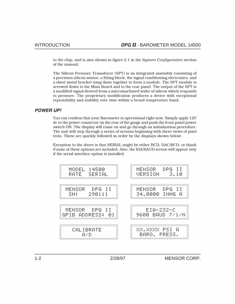
You can confirm that your Barometer is operational right now. Simply apply 12Vdc to the power connector on the rear of the gauge and push the front panel powerswitch ON. The display will come on and go through an initialization procedure.The unit will step through a series of screens beginning with three views of pixeltests. These are quickly followed in order by the displays shown below:
Exception to the above is that SERIAL might be either BCD, DAC/BCD, or blankif none of these options are included. Also, the EIA/BAUD screen will appear onlyif the serial interface option is installed.
INTRODUCTION DPG II - BAROMETER MODEL 14500
1-2 2/28/97 MENSOR CORP.

For the last screen, with no pressure connected, the Barometer will displayatmospheric pressure in the measurement units that were specified when theinstrument was ordered. This confirms that the DPG II is ready for work. If thisis your first time to use a DPG II please review the Warnings and Cautionsinformation on page iii. Then take the time to familiarize yourself with theInstallation and Operation sections of this manual as you go.
Figure 1.1 - Front View
DPG II - BAROMETER MODEL 14500 INTRODUCTION
MENSOR CORP. 2/28/97 1-3

EIA-232
OPTIONAL
CODE
SERIAL NUMBER
MODEL
V
Figure 1.2 - Rear View (Standard)(See Options section for Analog/BCD output rear panel)
INTRODUCTION DPG II - BAROMETER MODEL 14500
1-4 2/28/97 MENSOR CORP.

SYSTEM CONFIGURATION
The configuration switches in this instrument were set at the factory for thepressure units and options, as ordered. The initial setting for each Main Boardswitch is illustrated in Figure 2.1. No further changes are required for the gaugeto function. The user may choose other switch settings, as explained later, to setthe following:
· Select ZERO or SPAN mode for front panel – and + switches
· Enter sea level correction
· Display hourly barometric change
· Change output resolution
· Set GPIB address
· Select secondary measurement units
· Enable test modes
· Set up EIA-232 serial communications Port (see Options section)
FRONT PANEL –/+ SWITCHES
The two front panel switches marked – and + are used to adjust either the zeroor the span settings of the DPG II (and sea level corrections). Rear panel switchS2-1 and one internal switch determines which parameter is affected by the –/+switches. A full explanation of how these switches operate is included in the‘Calibration’ portion of the Maintenance and Calibration section.
DPG II - BAROMETER MODEL 14500 SYSTEM CONFIGURATION
MENSOR CORP. 2/28/97 2-1

ON ON
12
34
56
78
12
34
56
78
ON
1 2 3 4 5 6 7 8
Figure 2.1 - Printed Circuit Boards
SYSTEM CONFIGURATION DPG II - BAROMETER MODEL 14500
2-2 2/28/97 MENSOR CORP.

MEASUREMENT UNITS
The Barometer can output the pressure reading in any of the measurement unitslisted in table 2.2. The conversion factors used internally to convert from psi tothe other measurement units are listed in table 8.1 in the Appendix.
A front panel switch located to the right of the display provides the means tomanually select from a menu of pre-set engineering units. Pressing the switchwill display the current engineering unit. Holding the switch for approximately 2seconds will begin incrementing through the menu which consists of eight pre-setunits. The Barometer will be active in the units that are displayed when the switchis released.
The standard units loaded into the menu at the factory are seen in table 2.1,below. The first of the eight units (menu item one) is always psi. The second itemis determined by the settings of configuration switches S4-2 through S4-8 asshown in table 2.2. (The location of S4 is shown in figure 2.1).
The last six units (menu items 3 through 8) are optional, and can be set to anyof the measurement units of table 2.2 by means of a remote bus. The E(Engineering Units) Command in the Remote Operation section explains theprocedure for loading, changing or deleting menu items 3 through 8 over theGPIB or over an optional EIA-232 bus.
Table 2.1 – Standard Measurement Units
Menu Units Re-set Method
1 psi Base units – not re-settable
2 inH2O @ 4°C Set alternate units by configuring S4-2 through S4-8
3 inHg @ 0°C
Remove or change units for menu lines 3 through 8by re-loading over a remote bus.
4 hPa
5 mBar
6 Torr
7 mmHg @ 0°C
8 kPa
Note that the factory may have loaded other measurement units into menu items2 through 8 in response to a customer request at the time the instrument wasordered.
DPG II - BAROMETER MODEL 14500 SYSTEM CONFIGURATION
MENSOR CORP. 2/28/97 2-3
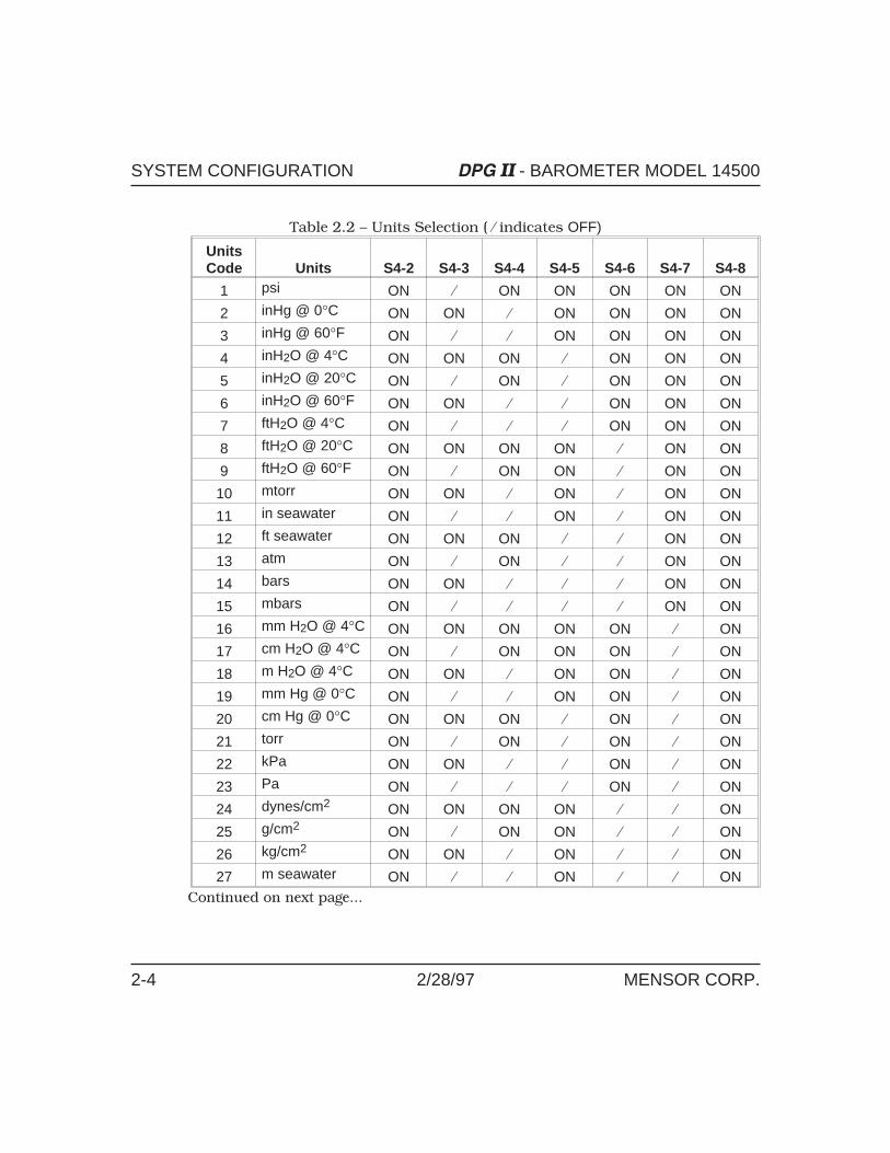
Table 2.2 – Units Selection ( � indicates OFF)
UnitsCode Units S4-2 S4-3 S4-4 S4-5 S4-6 S4-7 S4-8
1 psi ON � ON ON ON ON ON
2 inHg @ 0°C ON ON � ON ON ON ON
3 inHg @ 60°F ON � � ON ON ON ON
4 inH2O @ 4°C ON ON ON � ON ON ON
5 inH2O @ 20°C ON � ON � ON ON ON
6 inH2O @ 60°F ON ON � � ON ON ON
7 ftH2O @ 4°C ON � � � ON ON ON
8 ftH2O @ 20°C ON ON ON ON � ON ON
9 ftH2O @ 60°F ON � ON ON � ON ON
10 mtorr ON ON � ON � ON ON
11 in seawater ON � � ON � ON ON
12 ft seawater ON ON ON � � ON ON
13 atm ON � ON � � ON ON
14 bars ON ON � � � ON ON
15 mbars ON � � � � ON ON
16 mm H2O @ 4°C ON ON ON ON ON � ON
17 cm H2O @ 4°C ON � ON ON ON � ON
18 m H2O @ 4°C ON ON � ON ON � ON
19 mm Hg @ 0°C ON � � ON ON � ON
20 cm Hg @ 0°C ON ON ON � ON � ON
21 torr ON � ON � ON � ON
22 kPa ON ON � � ON � ON
23 Pa ON � � � ON � ON
24 dynes/cm2 ON ON ON ON � � ON
25 g/cm2 ON � ON ON � � ON
26 kg/cm2 ON ON � ON � � ON
27 m seawater ON � � ON � � ONContinued on next page...
SYSTEM CONFIGURATION DPG II - BAROMETER MODEL 14500
2-4 2/28/97 MENSOR CORP.

UnitsCode Units S4-2 S4-3 S4-4 S4-5 S4-6 S4-7 S4-8
28 oz/in2 ON ON ON � � � ON
29 psf ON � ON � � � ON
30 tsf ON ON � � � � ON
31 %FS ON � � � � � ON
32 mHg @ 0°C ON ON ON ON ON ON �
33 tsi ON � ON ON ON ON �
34 hPa ON ON � ON ON ON �
40 feet (altitude) ON ON ON ON � ON �
41 meters (altitude) ON � ON ON � ON �
If altitude units are enabled (codes 40 or 41) the hourly barometric change featurewill be disabled.
GPIB ADDRESS
Switches S2-4 through S2-8 on the rear panel will set the GPIB address per thefollowing table. To make a change, power OFF, set the switches, then power ON.( � indicates OFF.)
Table 2.3 – Setting the GPIB Address
GPIB Address S2-4 S2-5 S2-6 S2-7 S2-8
0 � � � � �
1 � � � � ON
2 � � � ON �
3 � � � ON ON
4 � � ON � �
5 � � ON � ON
6 � � ON ON �
7 � � ON ON ON
8 � ON � � �
Continued on next page...
**
*
DPG II - BAROMETER MODEL 14500 SYSTEM CONFIGURATION
MENSOR CORP. 2/28/97 2-5

GPIB Address S2-4 S2-5 S2-6 S2-7 S2-8
9 � ON � � ON
10 � ON � ON �
11 � ON � ON ON
12 � ON ON � �
13 � ON ON � ON
14 � ON ON ON �
15 � ON ON ON ON
16 ON � � � �
17 ON � � � ON
18 ON � � ON �
19 ON � � ON ON
20 ON � ON � �
21 ON � ON � ON
22 ON � ON ON �
23 ON � ON ON ON
24 ON ON � � �
25 ON ON � � ON
26 ON ON � ON �
27 ON ON � ON ON
28 ON ON ON � �
29 ON ON ON � ON
30 ON ON ON ON �
31 (not valid) ON ON ON ON ON
SYSTEM CONFIGURATION DPG II - BAROMETER MODEL 14500
2-6 2/28/97 MENSOR CORP.

TEST MODES
Certain diagnostics are automatically performed at initialization. In addition tothe self-tests, several other tests can be performed by setting internal switchesS3-1 through S3-4 (on the Main Board) per Table 2.4, below. Conversion Rate
displays the reading update rate currently being used by the DPG II. Dual A/D isa mode that displays the raw pressure and the temperature outputs of theanalog-to-digital converters for factory use. The last test, Switches, terminatesthe test procedures, and displays a graphic of all switch settings as currentlyconfigured, for S2 on the rear, and S3 and S4 on the main board (see figure 2.2).The rest of the tests are self explanatory. ( � indicates OFF.)
Table 2.4 – Test Modes
Test Mode S3-1 S3-2 S3-3 S3-4Normal Operation ON ON ON ON
RAM � ON ON ON
Display ON � ON ON
Ports � � ON ON
Conversion Rate ON ON � ON
Dual A/D (for factory use) � ON � ON
S/N ON � � ON
Range � � � ON
GPIB Address ON ON ON �
Switches (see figure 2.2) � � � �
To reset to another test, power down, set the switches for the desired test, thenpower up. Upon completion of all tests, reset S3-1 thru S3-4 to ON for normaloperation.
The carets (^) in figure 2.2 (next page) indicate switch 1 on S2, S3 and S4.
See figure 2.1 for the location and orientation of these three switcheswhich are mounted on the main board.
DPG II - BAROMETER MODEL 14500 SYSTEM CONFIGURATION
MENSOR CORP. 2/28/97 2-7

NOTE: Switch positions shown are for illustration purposes, only, and are
not intended to reflect your instrument.
OUTPUT RESOLUTION
Internal switch S4-1 on the Main Board can be set for standard resolution (ON),or high resolution, (OFF). Depending on the currently selected engineering units,the maximum resolution in standard mode is one part in 50,000, and in highresolution the maximum is one part in 500,000. Instruments normally areshipped with S4-1 set for high resolution output. High resolution can present avery nervous least significant digit for some ranges. In such cases switching tostandard resolution will provide a more readable display.
NOTE: The Barometer must be turned off before changing S4-1.
DISPLAY CONFIGURATION
The display is normally configured for standard pressure readings as seen infigure 1.1. The bottom line (BARO. PRESS.) can be replaced with an ‘hourlyBarometric change’ reading by placing switch S2-2 on the rear panel (see figure1.2) to ON (up).
In addition, the top and bottom lines of the display can be transposed asexplained under ‘CUSTOM DISPLAY’ in the Local Operation section, or thebottom line ‘BARO. PRESS.’ display can be replaced by a custom message enteredby the operator using the C Command as explained in the Remote Operationsection of this manual. All references to top and bottom display lines in thismanual refer to the standard configuration unless otherwise stated.
Figure 2.2 - Switch Configuration Display
SYSTEM CONFIGURATION DPG II - BAROMETER MODEL 14500
2-8 2/28/97 MENSOR CORP.

INSTALLATION
The DPG II combines the precision of a laboratory instrument with the rugged-ness of a field meter. It will perform equally well on a table top, mounted in arack, or in the field as a portable, battery powered instrument. See Options fordetails on rack adapters, carrying handles and battery packs.
MOUNTING
The special sensor used in the Barometer is relatively insensitive to tilt andvibration. However, to further assure stability and accuracy, excessive vibrationof the mounting surface should be avoided.
PRESSURE CONNECTION
The pressure port on the transducer is vented to atmosphere and comes with a1/8 NPT adapter fitting and a simple screen filter installed. If desired, a pressuresource can be connected to the 1/8 inch adapter by removing the filter andattaching the proper NPT hardware. Or, the 1/8 inch adapter can also be removedexposing the female threads of the transducer which are 7/16-20 SAE/MS straightthreads per MS16142 and SAE J514 table 14. This opening requires a tube fittingboss seal with an o-ring adapter per MS33656. When connections to a pressuresource are made, use a thread sealant such as Loctite Hydraulic Sealant or freshteflon tape on the male NPT threads. (Do not use thread sealant on fittings thatare sealed with an o-ring). The integrity of the seal is particularly important sinceeven microscopic leaks can cause errors in pressure measurements. A leak testis recommended after all connections are made.
NOTE: When making up connections to the o-ring adapter use a back-up
wrench to prevent over-stressing the threads in the aluminum block.
POWER ON
With the DPG II either vented to atmosphere or connected to a pressure source,and power connected to the rear of the gauge, push the power switch ON. Thegauge will go through a brief initialization process and system check. If a failureis detected, an error message will appear in the display. See Table 3.1 whichfollows and take the suggested action. If no errors are detected, the gauge is readyto use.
DPG II - BAROMETER MODEL 14500 INSTALLATION
MENSOR CORP. 2/28/97 3-1

ERROR CONDITIONS AND SUGGESTED ACTIONS
Table 3.1 – Error Conditions And Suggested Actions
Error Hex Dec Description Suggested Action
00 0 0 No error
01 41 65 RAM data error Contact Mensor.
02 42 66 RAM battery is low Contact Mensor.
03 43 67 Stack over/underflow Contact Mensor.
04 44 68 Command syntax error Check the command string forextra or incorrect characters.
05 45 69 Invalid parameter Check the numeric parameter tosee if it is in the valid range.
06 46 70 Input buffer overflow Too many characters were sentbefore an X was received.Resend.
07 46 71 Output buffer overflow Send command and read it backto keep buffer empty.
08 48 72 GPIB bus error A problem has been detectedwith the GPIB control lines.Check the controller and cablesfor proper connection.
09 49 73 Not used Contact Mensor.
10 4A 74 Display fault The display cannot be updated.Contact Mensor.
11 4B 75 A/D fault Contact Mensor.
12 4C 76 Calibration access error(for factory use)
An unauthorized attempt wasmade to enter the coefficients.Contact Mensor.
13 4D 77 Illegal switch code One of the setup switches(probably S4, units selection) isset incorrectly. Check S4.
14 4E 78 Range too low for altitudeengineering units
Range <14.4 psi. Change units.
Continued on next page...
INSTALLATION DPG II - BAROMETER MODEL 14500
3-2 2/28/97 MENSOR CORP.

Error Hex Dec Description Suggested Action
15 4F 79 Number > 1 million Contact Mensor.
16 50 80 Calculation overflow Power up, send GPIBcommands Z0X, S0X, N1X,N5X, then power OFF and backON. This sequence clears thezero and span offsets, andaverage readings. Otherwise,contact Mensor.
17 51 81 Division by zero Contact Mensor.
18 52 82 EIA-232 receiver overrun 73 characters received w/o X.Resend.
19 53 83 EIA-232 framing error Check all switch settings of S1and S2 on the optionalCommunications Board, thenresend.
20 54 84 EIA-232 parity error Parity incorrect if enabled. Checkand resend.
21 55 85 Attempting to monitor hourlychange when units are in feet ormeters, or when in sea level adj.
Change units, disable sea leveladj, or disable hourly changemonitor.
22 56 86 Not used Contact Mensor.
23 57 87 Not used
DPG II - BAROMETER MODEL 14500 INSTALLATION
MENSOR CORP. 2/28/97 3-3

User's Notes:
INSTALLATION DPG II - BAROMETER MODEL 14500
3-4 2/28/97 MENSOR CORP.

LOCAL OPERATION
The DPG II has two operating modes, LOCAL, which is hands-on, and REMOTE,which is from a computer over a communication bus. The LOCAL mode ofoperation for a standard instrument is covered in this section. REMOTE opera-tion is covered in the next section (Section 5). Section 6, Maintenance and
Calibration, provides information on performing specific calibration proceduresboth in the local and the remote modes, while Section 8, Options, gives detailson non-standard operating modes for the various optional features.
With the Barometer configured as explained in the System Configuration section,the following features and functions are available from the front and rear panelsexcept as noted.
STANDARD DISPLAY
In NORMAL mode the top line displays the pressure in the measurement unitsselected during system configuration. (See ‘Measurement Units’ in the System
Configuration section to change the displayed units). The bottom line will displayone of the following messages:
BARO. PRESS. normal display.BARO. PRESS. RT if GPIB talker is enabled.BARO. PRESS. RL if GPIB listener is enabled.ERROR:## for error indication.
CUSTOM DISPLAY
The top and bottom lines of the display can be transposed such that the bottomline appears on top, and the top line appears on the bottom. To transpose thetwo lines remove the rear panel screws and slide the Main board assembly outthe rear of the case. Locate header J9 (see figure 2.1) on the main board and usethe spare shunt provided there to connect pins 5 and 8. The display can berestored to normal operation by removing the shunt.
As an additional feature the bottom line of the instrument can be customized tosuit the user. This can be accomplished only over the GPIB bus (REMOTE) usingthe custom range display command. Refer to ‘C Command’ in the Remote
Operation section of the manual for details.
DPG II - BAROMETER MODEL 14500 LOCAL OPERATION
MENSOR CORP. 2/28/97 4-1

HOURLY BAROMETRIC CHANGE
NOTE: This feature is disabled if feet or meters are the active measurement
units (units codes 40 or 41).
The Hourly Barometric Change function calculates the hourly change in baro-metric pressure. This function is always active, but is seen on the display only ifrear panel switch S2-2, BARO CHANGE, is ON (up).
The Barometric Change function uses a special tracking buffer to store 60pressure readings which are one-minute running averages. If this function isenabled at power up the following sequence of events will occur:
The buffer is cleared during initialization, then immediately begins accumulatingthe average pressures over one minute intervals. During the first two one-minutepressure readings the bottom line of the display will show ??????? /HRe.
After the second minute, and for the remainder of the first hour, the instrumentbottom line will display snnnnnnn /HRe where:
s = arithmetic signnnnnnnn = calculated value up to seven digits/HR = per hour, ande indicates the value is an estimate.
(example: +0.123 /HRe)
During this first hour the estimated value is calculated by the formula:
(current reading – 1st reading) * 60 / (reading number – 1).
At the end of the first hour each additional reading received by the buffer displacesthe oldest reading stored there. The displayed value is then the difference betweenthe latest one minute average and the oldest one minute average. The display willdrop the e (estimate) and update the hourly change each minute thereafter usingthe formula:
(current reading – oldest buffer value)
LOCAL OPERATION DPG II - BAROMETER MODEL 14500
4-2 2/28/97 MENSOR CORP.
Note that the buffer and the calculations continue to operate at all times whilepower is applied, except when altitude units (unit codes 40 and 41) are active.Switching the BARO CHANGE switch ON merely sends the results to the display.
SEA LEVEL ADJUST
Sea level barometric readings can be corrected for local elevation with the SEALEVEL ADJUST feature. To enter the correction value first check that the currentunits are pressure units. SEA LEVEL ADJUST will not work if the instrument isset to units of altitude (feet or meters). Next, set rear panel switch S2-3 to SEALEVEL ADJUST (up) to enable the front panel + and – switches and change thebottom line of the display to read SEA LEVEL. In this mode when either the +or – switch is pressed the top line of the display will read SEA LEVEL ADJ:, andthe bottom line will indicate the current elevation as corrected.
Hold either of the two switches down for more than one second to cause the leastsignificant digit to begin incrementing or decrementing. Continue to hold theswitch until the display has reached the correct value for the local elevation.
The elevation units will display in feet if the selected engineering units are English,or in meters for metric engineering units. Table 5.2 shows which units are Englishand which are metric. The adjustment resolution is one unit, either foot or meter.The adjustment range is from 3000 feet below sea level (–3000 ft) to 30,000 feetabove sea level (+30000 ft). To reset the corrected elevation to zero (sea level)press both the + and the – switches and release them simultaneously.
Once the local elevation is entered, the Barometer converts the value to anequivalent pressure using the equation:
InHg = ( (FT – 145447.2 ) / – 76189.042 ) ^ 5.2561
The calculated value for local elevation is then algebraically added to a readingequivalent to sea level, yielding a sea level offset. This offset is then combinedwith the reading from the SPT and the result is output to the display and theremote bus.
Table 9.6 in the Appendix shows the calculated values at various elevations, andtable 9.7 gives the pressure offsets for the same elevations and units.
DPG II - BAROMETER MODEL 14500 LOCAL OPERATION
MENSOR CORP. 2/28/97 4-3

NOTES:
1. Switching S2-3 to SEA LEVEL ADJUST (up) overrides the ZERO and SPAN
adjusting functions of the front panel + and – switches.
2. Switching S2-3 to NORMAL (down) returns the Barometer to standard
display. However, switching S2-3 back to SEA LEVEL ADJUST will cause
the display to output a pressure corrected to the elevation last entered.
3. SEA LEVEL ADJUST will not work if units are in feet or meters.
ALTITUDE
The Barometer can measure pressure in equivalent feet or meters of altitudefrom –3000 to 100,000 feet. For accurate altitude output the current measure-ment units must be either feet or meters, the Sea Level Adjustment feature mustbe OFF, and the sea level correction value in memory must be zero.
See the ’Sea Level Adjust’ text under ‘Local Operation’ to manually re-zero aftera sea level correction has been entered. Then switch the Sea Level Adjust featureOFF (switch S2-3 set to NORMAL), and set the UNITS to either feet or meters.The equivalent altitude will appear on the display.
For REMOTE operation send L0X to re-set the sea level correction to zero and,if the Sea Level Adjustment feature is active, send LNX to turn it off. Then set theunits to feet or meters with the U command (see Table 5.2). The output will bealtitude, and can be displayed on the remote screen by sending the query Q0X.
NOTE: The uncertainty of the measured altitude output is given in table 7.1
under Specifications. The uncertainties shown in the table are in addition
to the other specified uncertainties.
LOCAL OPERATION DPG II - BAROMETER MODEL 14500
4-4 2/28/97 MENSOR CORP.

REMOTE OPERATION
The DPG II can be operated from a remote computer which communicates overthe IEEE-488-STD General Purpose Interface Bus, commonly referred to asGPIB. The computer must contain a GPIB card and must be connected to theDPG II with a standard IEEE-488 cable.
Software to install and operate the GPIB is provided by the manufacturer of theGPIB card, along with programming examples. The commands listed in thissection are the bare commands seen by the DPG II, stripped of all programmingidioms. Depending on the specific programming language used, it may benecessary to precede or enclose these commands in various symbols for trans-mission. A brief BASIC program has been included in the Appendix for yourconvenience, as an example.
For additional information on GPIB operation the complete IEEE-488-STDspecification is available from the Institute of Electrical & Electronics EngineersInc., 345 East 47th Street, New York, New York, 10017.
As options, the DPG II can be equipped with an EIA-232 serial port, a BCD outputor an analog output (see the Options section for details).
GPIB
The DPG II responds to device dependent commands and GPIB interfacecommands. The IEEE capability codes are:
SH1 . . . . . . . . . . full source handshake capabilityAH1 . . . . . . . . . full acceptor handshake capabilityT6 . . . . talker with serial poll and unaddress if MLAL4 . . . . . . . . . . . listener with unaddress if MTASR1 . . . . . . . . . . . full service request capabilityRL1 . . . . . full remote/local capability including LLOPPO . . . . . . . . . . . . no parallel poll capabilityDC1 . . . . . . . . . . . . . full device clear capabilityDT1 . . . . . . . . . . . . full device trigger capabilityE2 . . . . . . . . . . . . . . . . . . tri-state outputs
DPG II - BAROMETER MODEL 14500 REMOTE OPERATION
MENSOR CORP. 2/28/97 5-1

DEVICE ADDRESS
The primary address of the DPG II on the GPIB is set using the rear panel switchS2 as described in the System Configuration section. When the DPG II detectsa change in the address switches the new address is displayed for approximatelyone second.
SERVICE REQUEST
The service request line on the GPIB (SRQ) will be asserted when an error isencountered. See the Installation section for a table of the possible errorconditions and the suggested actions. If the controlling GPIB handler hasautomatic serial polling, and this feature is enabled, any errors will be cleared.
LOCAL LOCKOUT
When the DPG II is in the REMOTE mode, local lockout (LLO) is in effect. Theinstrument will not respond to any configuration switches changed manuallyuntil returned to the LOCAL mode.
STATUS DISPLAY
The DPG II indicates the status of the GPIB in the lower right corner of the display,where R=Remote, RL=Listener, RT=Remote Talker, and T=Talker only (LLOnot invoked).
GPIB INTERFACE MESSAGES
GPIB interface messages are standardized commands that are a function of theGPIB interface itself. These messages do not apply in any way to serial commu-nications.
The method of sending an interface message to the DPG II is dependent upon thespecific computer and interface hardware and software being used. The differ-ences occur primarily in the syntax used to invoke the desired command,particularly among different programming languages. Any GPIB controller (i.e.,a computer with a GPIB card) should have available the messages defined in thissection. They may, however, be identified differently in the actual programmingimplementation.
REMOTE OPERATION DPG II - BAROMETER MODEL 14500
5-2 2/28/97 MENSOR CORP.

DCLThe DEVICE CLEAR (DCL) command is used to reset the internal functions of alldevices on the GPIB that respond to this command. All input and output buffersare cleared and the DPG II is forced into the REMOTE mode when it receives aDCL. See also SDC.
GETThe GROUP EXECUTE TRIGGER (GET) is used to synchronize the acquisition ofdata between several instruments connected to the GPIB. When the DPG II
receives a GET the current GPIB output reading is latched until it is read overthe bus. The DPG II display will continue to update.
GTLThe GO TO LOCAL (GTL) command places the DPG II into the LOCAL mode. Thiswill allow the user to change the engineering units, resolution, etc. with theconfiguration switch on the rear panel (S2). The DPG II does not respond to anyswitch changes while in the REMOTE mode.
IFCThe INTERFACE CLEAR (IFC) command halts all current operations on the bus.
LLOThe LOCAL LOCKOUT (LLO) command prevents LOCAL operation of the instru-ment. The DPG II always has LLO enabled when the unit is in the REMOTE mode.
SDCSELECTED DEVICE CLEAR (SDC) is similar in function to DEVICE CLEAR (DCL)except that only the device addressed to listen is reset. If the DPG II address isselected it immediately goes into REMOTE mode.
Serial PollA SERIAL POLL is a high level function of the GPIB interface used to read thestatus byte of one particular device. Some GPIB interface manufacturers providethis as an automatic function, reading the most recent status byte from theinstrument after each read or write instruction. Others require the user tospecifically program the GPIB to do a SERIAL POLL of a device.
A common use of the SERIAL POLL is in a program module designed to respondto the service request (SRQ) line on the GPIB. Many GPIB interface manufacturers
DPG II - BAROMETER MODEL 14500 REMOTE OPERATION
MENSOR CORP. 2/28/97 5-3

provide a way to check the status of the SRQ line. If it is asserted, someinstrument on the bus requires service. The service may involve simply acknow-ledging a change in an instrument’s status, completion of an internal function ofthe instrument, or may indicate the existence of an error. The status byte returnedby the serial poll will determine the required service. In the case of the DPG II
the status byte will always read 0 (zero) unless an error condition exists. Referto Section 3, Installation, for a table of error codes and the suggested action ifan error message occurs.
DEVICE DEPENDENT MESSAGES
Device dependent messages are commands or queries specific to the DPG II thatare sent via a remote port (GPIB or EIA-232). These messages are devicedependent since they may not be valid for any other equipment. The DPG II
includes two types of device dependent messages: a), the terse command setwhich has been in use from the inception of the DPG II; and b), an expandedcommand set introduced with version 3.10 software. Some of the messages inthe expanded set invoke the same response as an equivalent message from theterse set. However, several new capabilities have been added with the expandedmessages. Either set of commands can be used, or they can be mixed.
All of the available messages, the transmission format and their purpose arepresented below. The newer, expanded messages are given first, in alphabeticalorder, followed by the older (terse) message set, also in alphabetical order. AQUICK REFERENCE of all of the messages is provided in table 9.9 in theAppendix. All of the messages included in both sets are usable, and can be freelyintermixed. Notice that all of the messages are insensitive to case, i.e., upper andlower case characters are interpreted the same by the DPG II.
Expanded Message SetThe complete listing of the usable messages added with version 3.10 software isgiven below. When sending a message from the expanded set to the DPG II overthe GPIB, the last character of the message must trigger an EOI to end themessage. A terminating line feed (<lf>) and/or carriage return (<cr>) is allowed,but is not required. Each message heading below is shown in output stringformat. The basic command is shown in all capital letters and the required orreturned variable is represented by lower case characters.
REMOTE OPERATION DPG II - BAROMETER MODEL 14500
5-4 2/28/97 MENSOR CORP.

DEFAULTThis command sets the default values for the DPG II.
The default values are: Filter window . . . . . . . 0.0025% full scaleFilter percent . . . . . . . . . . . . . . 90%Tare . . . . . . . . . . . . . . . . 0.0 (Off)Display . . . . . . . . . Pressure (normal)Passwords. . . . . . . . . . . . . . . . . . . . OnOutput format . . . . . . . . . . . . . . . . 0Digits . . . . . . . . . . . . . . . . . . . . . . . 6
DIGITS d (new command)The digits command sets the bus and display output resolution to five or sixdigits
where d is: 5 . . . . . . . . . for five digits, or6 . . . . . . . . . for six digits of resolution
DIGITS?The digits query returns the number of digits in the output resolution. The DPG
II returns: d<cr><lf>
where d is: 5 or 6, same as above
DISPLAY c (similar to T command)This command sets the display format
where c is: 0. . . . . . . . normal (same as D0 or T0 command)3. . . . . . . . hourly change (same as D5 or T5
command)
DISPLAY?This query will return: c<cr><lf>
Where c is: 0 to 5, same as above.
DOC? (new query)The DOC query returns the Date Of Calibration for the latest factory calibrationas: mm/dd/yy<cr><lf>
DPG II - BAROMETER MODEL 14500 REMOTE OPERATION
MENSOR CORP. 2/28/97 5-5

ERROR? (same as Q4X)This query will return either a two digit error code (see table 3.1),or: NO ERROR<cr><lf>
FILTER f (new command)The filter command sets the percentage of exponential filtering applied to thepressure readings
where f is: 0 to 99 percent filter
FILTER?This query returns two characters for the current percentage of exponential filter-ing as: f<cr><lf>
where f is two digits: 00 to 99 percent applied filter
ID? (same as Q2X)The ID query returns the four essential identity characteristics of the instrumentsuch as: MENSOR, DPG II, ssssss, v.vv<cr><lf>
where ssssss is:. . . . . . . . . . . Instrument serial numberwhere v.vv is:. . . . . . . . . . . . . Software version number
MASTER_CAL_ENABLE (new command)This is a password required to reset the span calibration factor over the bus.Sending this password also allows access to set the zero and tare offset values.The password requirement is turned off when this command is sent, and remainsoff until one of the following commands is issued: DEFAULT, DCL (device clear)or SDC (selected device clear), or until the next power-up. Any of these actionsre-instate the requirement for the password before the span calibration can bechanged.
OPT? (new query)The OPT query returns a list of the installed optionsas: MODEL mmmmm [,rrrr][,com]<cr><lf>
where mmmmm is: 14000 . . . . . Quartz Pressure Transducer (QPT)14500 . . . . . Precision Barometer15000 . . . . . Silicon Pressure Transducer (SPT)16500 . . . . . Quartz Resonant Transducer (QRT)
REMOTE OPERATION DPG II - BAROMETER MODEL 14500
5-6 2/28/97 MENSOR CORP.

rrrr is: blank
com is: SERIAL . . . . if EIA-232 option is installedBCD . . . . . . . if BCD output option is installedDAC/BCD . . . if the Analog output is included
with the BCD output optionor blank
RANGENEG? (similar to Q3X)This query will return the lower limit of the range in psi. This is normally zero,except that a bi-directional unit will return a negative value.
where –10.000 is: –10 psi
RANGEPOS? (similar to Q3X)This query will return the upper limit the of the range in psi
where 100.000 is: 100 psi
SEA_LEVEL_ENABLE (function reserved for Model 14500 Barometer)This is a password to enable access to the Sea Level offset. Once it is issued itremains in effect until a DEFAULT, DCL or SDC is received, or until the nextpower-up.
SEA_LEVEL s (function reserved for Model 14500 Barometer)This command must be proceeded by either the SEA_LEVEL_ENABLE or theMASTER_CAL_ENABLE password before the first occurrence of the SEALEVEL s command. This command is used to insert a local elevation correctionfor barometric pressure readings.
where s is: a value in feet if english units, ora value in meters if in metric units
SEA_LEVEL? (function reserved for Model 14500 Barometer)Returns the elevation correction as: s<cr><lf>
where s is: Same as above
DPG II - BAROMETER MODEL 14500 REMOTE OPERATION
MENSOR CORP. 2/28/97 5-7

SPAN s (similar to S command)
This command requires the MASTER_CAL_ENABLE command (password) beissued first for the SPAN s command to take effect. SPAN s corrects the pressurereading at full scale. Send the true pressure value (s) while maintaining at least50% of the FS pressure on the pressure port
where s is: true pressure in current engineering units
Notice the difference between this command and the older, abbreviated Scommand. The older command dealt with span as an offset, that is, the differencebetween the factory calibration full scale value and the desired full scale value.The newer SPAN s command takes as it’s parameter the desired value at thecurrent pressure. The expanded SPAN? query returns the multiplier used toarrive at the desired value.
Examples for a 15 PSIG unit:
Older S command:Send “S0X”Pressurize unit to 15.0000 PSIGUnit reads: 15.0002 PSIGSend “S-0.0002X”Unit now reads: 15.0000 PSIGSend “S?X”Unit responds: -.0002<cr><lf>
New SPAN command:Pressurize unit to 15.0000 PSIGUnit reads: 15.0002 PSIGSend “MASTER_CAL_ENABLE” (send EOI)Send “SPAN 15.0000" (send EOI with last character)Unit now reads: 15.0000 PSIGSend ”SPAN?" (send EOI with last character)Unit responds: 0.999987<cr><lf>
Either command or query will be accepted, and the DPG will return values ap-propriate to the type of command or query it receives.
SPAN?The Span query will return the span correction scale factor as: s<cr><lf>
REMOTE OPERATION DPG II - BAROMETER MODEL 14500
5-8 2/28/97 MENSOR CORP.

where s is: a value from 0.90000 to 1.10000(see example under “New SPAN command” above)
TARE_CAL_ENABLE (new command)This is a password to enable access to the Tare offset. Once it is issued it remainsin effect until a DEFAULT, DCL or SDC is received, or until the next power-up.
TARE t (new command)This command must be proceeded by either the TARE_CAL_ENABLE or theMASTER_CAL_ENABLE password before the first occurrence of the TARE tcommand. TARE t sets the tare offset
where t is: a value between +/– 17 psi
TARE?This query returns the current tare calibration variable as: t<cr><lf>
where t is: current tare offset in current engineering units
TYPE? (new query)Returns the type of pressure sensor in the instrument
as: ABSOLUTE<cr><lf> for an absolute pressure sensoror GAUGE<cr><lf> for a gauge pressure sensor
UNITS u (same as U command)This command selects the engineering units to be output on the bus and displayfor all subsequent pressure readings
where u is: 0 to 47 from the Units Codes in Table 5.2
UNITS?This query will return the units code and the ASCII string for the unitsas: 01,PSI<cr><lf>
UNITS_TABLE? (new query)This query will return the current table of up to eight engineering units stored inthe register for the front panel UNITS switch
DPG II - BAROMETER MODEL 14500 REMOTE OPERATION
MENSOR CORP. 2/28/97 5-9

as: nn,ascii<cr>nn,ascii<cr>nn,ascii<cr>nn,ascii<cr>nn,ascii<cr>nn,ascii<cr>nn,ascii<cr>nn,ascii<cr><lf>
where each nn is: the units code listed in register sequenceand ascii is: the nomenclature for each of the engineering units
WINDOW w (new command)Sets the operating window for the pressure reading exponential filter
where w is: any value within the range of the instrument inthe current engineering units
WINDOW?Returns the current exponential filter value for the pressure output in the cur-rent engineering units as: w<cr><lf>
where w is: a number value within the range of the instrumentin the current engineering units
ZERO_CAL_ENABLE (new command)This is a password to enable access to the zero offset. Once it is issued it remainsin effect until a DEFAULT, DCL or SDC is received, or until the next power-up.
ZERO zThis command must be proceeded by either the ZERO_CAL_ENABLE or theMASTER_CAL_ENABLE password before the first occurrence of the ZERO zcommand. ZERO z sets the zero offset
where z is: a value between +/– 1.0 psi
ZERO?This query returns the current zero calibration offset as: z<cr><lf>
where z is: current zero offset in current engineering units
REMOTE OPERATION DPG II - BAROMETER MODEL 14500
5-10 2/28/97 MENSOR CORP.

Terse Message SetThe following device dependent messages include the original terms enabled forthe DPG II. Most of these terms have an equivalent message in the above,expanded message list. When sending a terse message to the DPG II, transmitthe message followed by an X. The X signals the DPG II to execute the commandcontained in the message.
C Command (no equivalent expanded command)The C command is used to customize the range display on the DPG II. The newmessage must be 1 to 14 alpha (upper case only), numeric and/or some symbolcharacters. The message will be left justified, and unused characters will beblanked to the right. The command format is: CdaaaaaaaaaaaaaadX
where: C or c = custom range display commandd = delimiter: square brackets ([]).
a = capital letters, numbers and symbols(except ? or []) making up the new messageto be displayed.
Examples:
1. Replace standard display of “ 30.0000 FS” with “ 15.0000 FS”Send: C[ 15.0000 FS]X
2. Replace standard display of “ 500.000 FS” with “ A COMPANY NAME”Send: C[A COMPANY NAME]X
To return the unit to normal display send: C[]X
D or T Command (Barometric Change)Sending D5X or T5X over the bus enables the hourly barometric change feature.The functional description of this feature was provided in the Local Operation
section. To turn off the barometric change issue D0X or T0X.
E Command (no equivalent expanded command)As stated under ‘Measurement Units’ in Section 2, System Configuration, the Ecommand is used to re-load the last six of the eight engineering units that areswitch-selectable from the front panel of the DPG II. These six units (3 through8) were set at the factory to the customer’s request, or were left empty.
DPG II - BAROMETER MODEL 14500 REMOTE OPERATION
MENSOR CORP. 2/28/97 5-11

To change any or all of these six units send Enn,nn,nn,nn,nn,nnX
where: nn = a desired unit code from the U Command table (table 5.2)
or: nn = 99 to eliminate a unit from the list. Sending a series of six99s would shorten the list to two units: 1 = psi; and 2 = asconfigured by switches S4-2 through S4-8.
NOTE: nn can be either one or two characters. For example, sending either
5 or 05 over the bus would set that units slot to inches of water @ 20°C
(INH20 @ 20°C).
Q Command (similar to some expanded commands)The Q command is a request for data from the DPG II. The output data will beformatted according to the specific form of the Q command. Output formats 0and 1 will remain selected until changed by a subsequent Q command. Outputformats 2 through 7 will be in effect for one output cycle only, after which theformat will revert to 0 or 1, whichever was last being used.
REMOTE OPERATION DPG II - BAROMETER MODEL 14500
5-12 2/28/97 MENSOR CORP.

The syntax for the Q command is QnX where n is a number (0 through 7) asdescribed in table 5.1. The table also lists the resulting output format for eachvalue of n.
space = an ASCII space character (32 dec)<cr> = an ASCII carriage return (13 dec)<lf> = an ASCII linefeed (10 dec)EOI (End Of Instruction) is set with the <lf> (on the GPIB)
Table 5.1 – The ‘Q‘ Command Data/Output Format
n Description Output Format
0 Pressure reading in theselected units. This is thedefault output format.
NNNNNNN <cr><lf> where each N is a number (0through 9), +, –, decimal point, or a space. If thepressure rate or peak monitor option is being usedthe output format is NNNNNNN,NNNNNNN<cr><lf>. The data before the comma is thepressure and the data after the comma is thepressure rate or peak.
1 Raw A/D readings (forfactory use)
nnnnnnn,nnnnnnn <cr><lf> where each n is anumber (0 through 9) or a space.
2 Unit ID MENSOR, DPG II, nnnnnn, n.nn <cr><lf> where each n is
a number (0 through 9) in ASCII code representing the unit serial
number and the firmware version of the unit.
3 Pressure range andmeasurement units
NNNNNNN,NNNNNNN, @@@@@@@<cr><lf> where each Nis a number (0 through 9), decimal point, or a space and each @is an alpha-numeric character. The output string represents the
minimum pressure, maximum pressure and the pressure units.
4 Error status code Enn <cr><lf> where each n is a number (0 through 9)
representing the error status.
5 Calibration data Factory use, only.
6 Pressure rate or peak Not applicable to the precision Barometer.
7 Zero and span corrections ZZZZZZZ,SSSSSSS <cr><lf> where ZZZZZZZ is the zero
correction and SSSSSSS is the span correction.
8 Calibration coefficients Factory use, only.
Note: The Q1X command changes the output units to counts, and Q0X resets it to defaultunits.
DPG II - BAROMETER MODEL 14500 REMOTE OPERATION
MENSOR CORP. 2/28/97 5-13

S Command (same as SPAN command)
See Maintenance and Calibration, Section 6.
U Command (same as UNITS command)The U command selects the measurement units to be output on the bus and the display.
The syntax for the U command is UnX where n is a number as described in table 5.2.
Table 5.2 – The ‘U’ Command Syntax for Measurement Units
n Description Output Format Type
0 internal counts COUNTS RAW DATA
1 pounds per square inch PSI
2 inches of mercury @ 0°CINHG
3 inches of mercury @ 60°F
4 inches of water @ 4°C
INH2O5 inches of water @ 20°C ENGLISH
6 inches of water @ 60°F
7 feet of water @ 4°C
FTH2O8 feet of water @ 20°C
9 feet of water @ 60°F
10 millitorr MTORR METRIC
11 inches of sea water INSW
12 feet of sea water FTSW ENGLISH
13 atmospheres ATM
14 bars BAR
15 millibars MBAR
16 millimeters of water @ 4°C MMH2O METRIC
17 centimeters of water @ 4°C CMH2O
18 meters of water @ 4°C MH2OContinued on next page...
REMOTE OPERATION DPG II - BAROMETER MODEL 14500
5-14 2/28/97 MENSOR CORP.

(Table 5.2 Continued...)
n Description Output Format Type
19 millimeters of mercury @ 0°C MMHG
20 centimeters of mercury @ 0°C CMHG
21 torr TORR
22 kilopascals KPA METRIC
23 pascals PA
24 dynes per square centimeter DY/CM2
25 grams per square centimeter G/CM2
26 kilograms per square centimeter KG/CM2
27 meters of sea water MSW
28 ounce per square inch OSI
29 pounds per square foot PSF
30 tons per square foot TSF
31 percent of full scale %FS ENGLISH
32 micron of mercury @ 0°C MHG
33 tsi TSI
34 hPa HPA METRIC
40 feet of altitude FEET ENGLISH
41 meters of altitude METERS METRIC
43 miles per hour MPH
44 knots KNOTS ENGLISH
45 meters per second M/S
46 kilometers per hour KM/H METRIC
47 mach MACH
Differential or gauge units will not display altitude (units 40 and 41).The subsonic “calibrated” air speeds and mach numbers are calculated froma differential pressure measurement with the reference pressure at standardsea level (1013.25 mBars). Absolute measuring instruments will not displayair speed (units 43 through 47).
Z Command (same as ZERO command)See Section 6, Maintenance and Calibration.
**
*
**
**
**
**
**
*
*
DPG II - BAROMETER MODEL 14500 REMOTE OPERATION
MENSOR CORP. 2/28/97 5-15

ALTITUDE
This feature allows the DPG II to measure pressure equivalent to feet or metersof altitude, from –3000 to 100,000 feet. To enable this feature locally see the tableof ‘Measurement Units’ in Section 2, System Configuration, and set the switchesfor feet or meters as shown. When pressure is applied to the instrument, it willdisplay the altitude which is equivalent to that pressure. Altitude pressure unitsare measured in terms of absolute pressure, only.
To configure the system for altitude from a remote station, see Table 5.2 for‘Units’ in Section 5, Remote Operation. Establish communication from thecomputer to the gauge over the bus.
The syntax for feet is U40X and for meters it is U41X.
The equivalent altitude will appear on the display. To see the output on the remotesystem, address the DPG II as a talker and read the altitude value.
NOTES:
1. The uncertainty of altitude measurement is given in table 7.1 of altitude
ranges under Specifications, Section 7. These uncertainties are in addition
to the other specified uncertainties.
2. Altitude in this instrument is calculated according to a set of formulas
that match the ICAO 1964 standard atmosphere. Table 7.1 in the Specifi-
cations section relating to the uncertainty of altitude is based on the
published ICAO standard atmosphere tables.
REMOTE OPERATION DPG II - BAROMETER MODEL 14500
5-16 2/28/97 MENSOR CORP.
MAINTENANCE AND CALIBRATION
MAINTENANCE
This instrument was designed for maintenance-free operation. The Main boardhas a replaceable 0.8 amp fuse and two configuration switches, S3 and S4, whichmay require access on occasion (see figure 2.1). Otherwise, there are no userserviceable components inside the unit. Mensor Corporation provides completemaintenance and calibration services beyond the warranty period, for a nominalfee. Call 1-512-396-4200 or 1-800-984-4200 (USA only) for details.
CALIBRATION
The DPG II Barometer automatically adjusts the pressure reading for the effectsof temperature and non-linearity within the calibrated temperature range of0–50°C. The process is referred to as dynamic compensation because eachreading is adjusted before it is output to the display or to the communicationport(s). Thus, a calibrated DPG II operated within that temperature band, andwith proper zero and span adjustments, will provide accurate barometric meas-urements.
The DPG II should have the zero and span verified periodically to insure theinstrument’s stability. Initially, the recommended period between calibrations isthree months. This period may be extended as confidence is gained in the spanstability.
Calibration EnvironmentFor maximum accuracy the Barometer should be operated in an ambienttemperature which is stable and within the specified calibration range. Inaddition the instrument should be at rest on a stable platform which is free ofvibration and shock as described in the Installation section.
DPG II - BAROMETER MODEL 14500 MAINTENANCE AND CALIBRATION
MENSOR CORP. 2/28/97 6-1
Calibration StandardThe recommended pressure standard is a piston gauge type (deadweight gauge)with an uncertainty of 0.01% of reading or better. A vacuum gauge with anaccuracy of 0.5% of reading at 250 to 300 millitorr is recommended for settingzero.
Calibration MediumThe recommended calibration medium is dry nitrogen or clean, dry instrumentair.
Calibrating the DPG II BarometerThe procedures for calibrating a DPG II from the front panel (LOCAL) are givenfirst, followed by the procedures for calibrating over a bus using a computer(REMOTE). Figure 6.1, which illustrates a calibration setup, shows the additionalequipment required for remote calibration as optional.
In the illustration the ‘Pressure Standard" is normally a deadweight test instru-ment, and the ‘Volume Controller’ refers to a hand operated variable-volumepressure vernier device. A diaphragm type vacuum gauge is recommended overthe gauge tube type of vacuum sensor for calibrating sub-atmospheric pressures.
NOTE: When this instrument was calibrated at the factory the zero and span
corrections were stored in memory. If the zero or span values are changed
at the front panel, or over the remote bus, the new values immediately
displace the factory values in memory. It is recommended that a permanent
record be maintained of the ‘as received’ values, as well as the values that
result from each subsequent zero and span update.
NOTE: Psi are the recommended units for making zero or span adjustments.
Other engineering units might add a small roundoff error.
MAINTENANCE AND CALIBRATION DPG II - BAROMETER MODEL 14500
6-2 2/28/97 MENSOR CORP.

CAUTION: THE TUBING, VALVES AND OTHER APPARATUS MUST
BE ADEQUATE FOR THE PRESSURE RANGE, OTHERWISE PHYSI-
CAL INJURY TO THE OPERATOR OR BYSTANDERS IS POSSIBLE.
PRESSPRESSURESTANDARD
VACUUM
PRESSURE
SHUT-OFFVALVES
VOLUMECONTROLLER
VENT
GPIB orOPTIONAL EIA-232
LINEREGULATOR
PRESSURESUPPLY
SHUT-OFFVALVES
VENT
METERINGVALVE
DIAPHRAGM TYPEVACUUM GAUGE VAC
DPG II
COMPUTER(OPTIONAL)
NOTE: DISCONNECT WHEN VACUUMGAUGE RANGE IS EXCEEDED
12VDC
POWER
EIA-232
DIGITAL PRESSURE
GAUGE II
Figure 6.1 - Calibration Setup
DPG II - BAROMETER MODEL 14500 MAINTENANCE AND CALIBRATION
MENSOR CORP. 2/28/97 6-3

Local Zero AdjustmentConnect a vacuum pump of at least 21 liters per minute capacity to the rear panel.Evacuate to a low pressure that will still maintain a viscous flow, typically 500millitorr. At lower pressures, with viscous flow interrupted, the vacuum readingsare less reliable and the actual pressure at any particular point in the system isthen questionable.
When the target vacuum has stabilized convert the millitorr reading to anequivalent instrument reading for the active measurement units. Millitorr con-version factors are provided in table 9.2 in the Appendix.
Set the rear panel switches S2-1 through S2-3 in the down position (ZERO,NORMAL, NORMAL). In this condition the front panel switches are enabled forzero adjustment. Press either – or + to display the current zero offset in the activemeasurement units. Hold either of the two switches down for more than onesecond to cause the offset to begin incrementing or decrementing the leastsignificant digit. The longer a switch is held the faster the digits will change upto the maximum zero adjustment range of approximately ±16 psi.
Local Span AdjustmentTo enable the front panel – and + switches to affect the span adjustment setinternal switch S3-8 to OFF (see Figure 2.1), and rear panel switch S2-1 to SPAN(up), and S2-2 and S2-3 to NORMAL (down). Then press either the – or the +switch to cause the instrument display to show the current offset from full spanin the active measurement units. To change the span offset hold either the – orthe + switch to increment or decrement the offset value as desired, up to amaximum of ± 0.1% of instrument span (± 0.017 psi). To remove the offset, pressboth the – and the + switches and release them simultaneously.
Remote Zero AdjustmentRefer to figure 6.1 for the recommended setup. Connect a vacuum pump to thepressure port. Evacuate the sensor to approximately 500 millitorr.
Convert the vacuum reading to an equivalent instrument reading for the activemeasurement units. Millitorr conversion factors are provided in Table 9.2 in theAppendix.
Send Z0X to clear the stored zero correction from RAM.
MAINTENANCE AND CALIBRATION DPG II - BAROMETER MODEL 14500
6-4 2/28/97 MENSOR CORP.

Record the DPG II output. Next subtract the vacuum reading (in equivalent units)from the instrument reading. This difference will be the zero offset.
The sign of the zero correction value will be opposite to that of the zero offset.Send the zero correction using the Z(value)X command. The maximum numberof characters allowed in the correction value is seven (7), including the decimalpoint and the minus sign, if needed.
Example: For a 0-15 psia unit with a 500 millitorr vacuum applied,using psi units:
DPG II output = -0.0029 psia500 millitorr = 0.0097 psi absolute pressure-0.0029 (-) 0.0097 = -0.0126 psi offsetCorrection value = +0.0126
Send Z.0126
The DPG II should now display .0097 psia.
Remote Span AdjustmentThe syntax for span adjustment is SnX where n is a numeric value to be sent overthe bus.
Send S0X to clear the stored correction.
Apply a known pressure equal to the span of the instrument.
Get the reading from the DPG II.
Subtract the applied pressure from the DPG II reading. The result is the spanoffset. Invert the sign of the span offset to obtain the correction value.
Send the correction using the S(value)X command. The maximum number ofcharacters allowed in the correction value is seven (7), including the decimalpoint, and, if applicable, a minus sign.
NOTE: Span adjustment can be accomplished using the newer ‘Span s’
command as shown under ‘Remote Operation’, Section 5.
DPG II - BAROMETER MODEL 14500 MAINTENANCE AND CALIBRATION
MENSOR CORP. 2/28/97 6-5

Correction Value QueryThe stored corrections for zero and span can be retrieved over the communica-tion ports using the Q7X command. See ‘Device Dependent Messages’ in theRemote Operation section of this manual for specific details. This command maybe useful in determining the actual changes in zero and span. Unauthorizedalterations of the values can be detected by comparison with recorded values forthe corrections.
MAINTENANCE AND CALIBRATION DPG II - BAROMETER MODEL 14500
6-6 2/28/97 MENSOR CORP.

SPECIFICATIONS
These specifications apply to a Mensor Precision Barometer consisting of a DPG
II incorporating a specially calibrated Silicon Pressure Transducer (SPT). Thisinstrument is available with various accuracy and temperature range configura-tions as shown in table 7.1 below. These specifications are subject to changewithout notice.
RANGES
(Before Zero adjustment, Span adjustment, or Sea Level Correction)
Displayed Range: –1.66 to 21.58 psia (–3.39 to 43.94 inHgA)Calibrated Range: 0 to 17 psia (0 to 34.6 inHgA)
PRESSURE MEDIUM
Clean, dry, non-corrosive gases unless otherwise specified on the factory calibra-tion reports. The DPG II is not intended for use with oxygen as the pressuremedium.
UNCERTAINTY
TransducerOver the full calibrated range of 0 to 17 psia (0 to 34.6 inHgA), and within thecompensated temperature range, the measurement error due to the combinedeffects of hysteresis, repeatability, linearity and temperature is 0.01% of full scaleexcept as noted for Model 14500C as shown in table 7.1.
Table 7.1 – Accuracy/Temperature Configurations
MODEL ACCURACY TEMP RANGE
14500A 0.010% R 0 to 50°C
14500B 0.010% R 15 to 45°C
14500C 0.025% R 15 to 45°C
Between 10.8 and 16.7 psia (22.0 to 34.0 inHgA @ 0°C) the combined uncertaintyis 0.01% of reading for types A and B, and 0.025% of reading for type C.
DPG II - BAROMETER MODEL 14500 SPECIFICATIONS
MENSOR CORP. 2/28/97 7-1
Digital OutputThe DPG II has an additional uncertainty of one half the value of the leastsignificant digit of the output (display, bus or optional BCD).
Analog OutputThe uncertainty of the analog output option (0–10 vdc) is 0.05% of full scale. Thisuncertainty is in addition to the stated uncertainty of the transducer.
Calibration Standard0.01% of reading or 0.0001 psi, whichever is greater.
Measurement Error Due To Temperature ChangeLess than 0.001% of full scale per degree Celsius of temperature change withinthe compensated temperature range under controlled (test chamber) conditions.However, the observed effect may appear somewhat greater in environments withcommonly encountered temperature variations.
Altitude Pressure Units and Local Elevation CorrectionAltitude pressure units (feet, meters) and local elevation corrections have anadditional uncertainty of the following:
Table 7.2 – Additional Uncertainty of Altitude/Feet
Altitude, Feet: Additional Uncertainty-3000 to 5000 3 feet
5001 to 30000 4 feet
HOURLY BAROMETRIC CHANGE
The readings used to calculate hourly change are taken at one-minute intervalswith a timing uncertainty of +0.05 second per minute. The cumulative timingerror is no greater than +0.25 seconds per hour.
COMPENSATED TEMPERATURE RANGE
0 to 50°C (type A) or 15 to 45°C (type B or C) as shown in table 7.1. Specialcalibrations for other temperature ranges are available. Contact Mensor fordetails.
SPECIFICATIONS DPG II - BAROMETER MODEL 14500
7-2 2/28/97 MENSOR CORP.

OUTPUT RESOLUTION
Up to 2 parts per million depending on the range of the currently selected units.In STANDARD mode the full scale resolution will be between 5,000 and 50,000.In HIGH mode the same units will have a full scale resolution between 50,000and 500,000.
Optional Outputs0–5 vdc or 0–10 vdc analog into a 2K ohm (max.) load, provides 1 part in 4096resolution.24 lines BCD data and 8 status lines (LSTTL compatible) capable of 0–999,999.
RESPONSE TIME
Less than 0.2 seconds for 100% of full scale pressure step input (update rate isapproximately 120 per second).
WARM-UP
Approximately 15 minutes.Zero Drift: (after warm-up)
0.01% full scale 30 daysZero may be reset without affecting span or linearity.
Span Drift: (full scale reading minus zero reading, after warm-up)0.01% full scale 90 daysSpan may be reset without affecting zero or linearity.
OVER PRESSURE RATING
45 psia maximum.
ATTITUDE ERROR
Negligible in any attitude (orientation).
OPERATING ENVIRONMENT
Temperature: 0°C to 50°C. Note: This is not the compensated temperaturerange.
Humidity: 5% to 95% RH non-condensing humidity.
DPG II - BAROMETER MODEL 14500 SPECIFICATIONS
MENSOR CORP. 2/28/97 7-3

SHIPPING, STORAGE AND HANDLING ENVIRONMENT
-20 to 70°C.Minimal vibration.5 gravities acceleration maximum.Non-condensing humidity.
OUTPUTS
Front Panel DisplayIEEE 488.1-1978 Interface Bus (GPIB)
Optional: EIA-232 Serial Port0–10 vdc analogBinary Coded Decimal (BCD)
DISPLAY
Two lines of 16 each 0.2 inch high characters.Vacuum fluorescent, blue filter.
POWER
Requires 10 to 15 vdc @ 600 mA.
FUSE
0.8 amp (See figure 2.1).
MOUNTING
Table model is standard. A rack adapter and carrying handle are available.
PRESSURE CONNECTION
The pressure port on the transducer is a female 7/16–20 SAE/MS straight threadper MS16142 and SAE J514 table 14. It requires a tube fitting boss seal with ano-ring per MS33656. Mensor provides a 1/8 NPT adapter and a 1/8 NPT filterwith the SPT. Connections can be made to the adapter or directly to thetransducer port with the proper fitting.
SPECIFICATIONS DPG II - BAROMETER MODEL 14500
7-4 2/28/97 MENSOR CORP.

SIZE
7.56" wide x 3.78" high x 9.50" deep (19.20 cm x 9.60 cm x 24.38 cm).7.56" wide x 6.00" high x 9.50" deep (19.20 cm x 15.24 cm x 24.38 cm) withoptional battery pack.
3.6"(9.14 cm)
3.78"(9.60 cm)
SIDE VIEW
9.5" (24.13 cm)
7.25"(18.42 cm)
7.56"(19.20 cm)
TOP VIEW
FIGURE 7.1 - DIMENSIONAL OUTLINE
DPG II - BAROMETER MODEL 14500 SPECIFICATIONS
MENSOR CORP. 2/28/97 7-5
WEIGHT
4.7 pounds (2.13 kg).9.0 pounds (4.08 kg) with optional battery pack.
TRANSDUCER VOLUME (CUBIC CENTIMETERS)
Pressure Chamber: 0.6 cc
SPECIFICATIONS DPG II - BAROMETER MODEL 14500
7-6 2/28/97 MENSOR CORP.

OPTIONS
Part Number Page
POWERPlug-in module . . . . . . . . . . . . . . . . . . . . 0014035001100 to 125 volts, 50/60 Hz9 to 12 vdc @ 750 mA.
Plug-in module . . . . . . . . . . . . . . . . . . . . 0014035002200 to 250 volts, 50/60 Hz12 to 14 vdc @ 750 mA.
Battery Pack-Portable . . . . . . . . . . . . . . . . 0014080001 . . . . . 8-212 vdc @ 4 amp HourBattery Pack Kit . . . . . . . . . . . . . . . . . . . 0014080002 . . . . . 8-2Battery Charger . . . . . . . . . . . . . . . . . . . 0014095001 . . . . . 8-3
Power Cord, 12 vdc/Automotive . . . . . . . . . . . 0014089001 . . . . . 8-3
RACK MOUNT KITOne DPG . . . . . . . . . . . . . . . . . . . . . . . 0011455001 . . . . . 8-3Two DPG’s . . . . . . . . . . . . . . . . . . . . . . 0011455002Panel Mount Hardware . . . . . . . . . . . . . . . 0011455003
HANDLE KIT . . . . . . . . . . . . . . . . . . . . . 0014034001 . . . . . 8-4
CARRYING CASE . . . . . . . . . . . . . . . . . . several available . . . . . 8-5
EIA-232 INTERFACE . . . . . . . . . . . . . . . . 0014014001 . . . . . 8-6
ANALOG OUTPUT . . . . . . . . . . . . . . . . . . 0014014001 . . . . . 8-9
BCD OUTPUT . . . . . . . . . . . . . . . . . . . . . 0012976002 . . . . . 8-10
DPG II - BAROMETER MODEL 14500 OPTIONS
MENSOR CORP. 2/28/97 8-1


BATTERY CHARGER (0014095001)
To recharge the battery pack plug a battery charger into the socket provided inthe center on the rear of the battery pack case. Total charging time for a fullydischarged battery pack is 10 hours with the DPG II turned off.
NOTES:
1. The voltage select switch located on the bottom of the charger must be set
for the local line voltage (115 or 220 VAC) before plugging it into a power
source.
2. While it is possible to operate a DPG II from the battery charger while it
is charging, the charging time will be greatly extended.
AUTOMOTIVE POWER CORD (0014089001)
The automotive power cord patches between a 12 volt automobile cigarettelighter, and the power connector on the rear of the DPG II. The cord includescurrent limiting circuitry to protect both the instrument and the car battery. Useonly a Mensor supplied automotive power cord for this purpose.
RACK MOUNT KIT (001145500X)
The rack panel is available with either one or two cut-outs for mounting DPG IIs.The panel fits a 5-1/4 inch opening in a standard 19 inch rack. To mount aninstrument into the panel simply insert it into a panel cutout from the front untilthe DPG II front bezel stops it. Then, from the rear of the instrument slide thetwo clamp bars into the extruded slots on either side of the instrument case untilthe bars rest against the inside of the rack panel. Finally, run the #6-32 Allen setscrews against the tail end of each of the clamp bars to apply clamping pressureagainst the rack panel.
DIGITAL PRESSURE GAUGE
POWER
ERO
+
RACK PANEL
CLAMP BAR
6-32 SET-SCREW
SECOND CUT-OUTOPTIONAL
Figure 8.2 - Rack Mount Diagram
RACK PANEL
DPG II - BAROMETER MODEL 14500 OPTIONS
MENSOR CORP. 2/28/97 8-3

HANDLES
Two different handles are available for the DPG II as shown in figure 8.3. If eitherhandle is ordered at the time an instrument is ordered it will be mounted byMensor prior to shipment. However, both handles are available in kit form andcan be ordered separately. Each handle kit will include all of the necessaryhardware and mounting instructions.
Carrying Handle (0014034001)The 0014034001 Carrying Handle is a collapsible, stitched-leather handle withchrome fittings. This handle is easily attached and removed, and is suitable forcarrying any DPG II. While it is customary to mount this handle on the top, it canbe mounted to either side that is not otherwise occupied.
Tilt-Stand/Carrying Handle (0014068001)The 0014068001 Tilt-Stand/Handle is a foldable, vinyl coated, formed steel rodwith mounting brackets. When folded down it acts as a tilt stand as seen in figure8.3, or it can be folded forward to use as a carrying handle. This device is notsuitable for use with a battery powered DPG II.
NOTE: The screws that secure the two side brackets for the tilt stand are
self-tapping screws that thread themselves into the case channels. If the
brackets are removed or relocated the removed screws will leave bright
metallic screw tracks in the black channels.
Figure 8.3 - Handles
OPTIONS DPG II - BAROMETER MODEL 14500
8-4 2/28/97 MENSOR CORP.

CARRYING CASES (0014259001, 0014261001 AND 14289001)
Mensor offers a vanity case style and two briefcase styles of carrying cases forthe DPG II. Each case is constructed of a high impact plastic exterior, aninterlocking tongue and groove opening, a vinyl handle, and nickle-chromefixtures. Each case has an interior filled with high density polyurethane foamwith a die-cut cavity to cushion the instrument. There are additional cavities tostore related accessories, and the manual. Contact Mensor for the particularcarrying case to best suit your application.
Top View
10" (25.40 cm)(NOM)
12" (30.48 cm)(NOM)
Front View
3" (7.72 cm)
7" (17.78 cm)
(brief case style also available)
Figure 8.4 - CARRYING CASE (0014261001 shown)
DPG II - BAROMETER MODEL 14500 OPTIONS
MENSOR CORP. 2/28/97 8-5
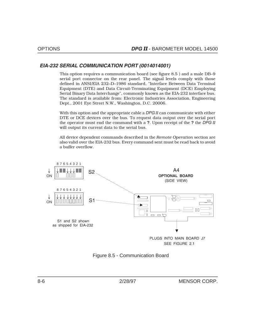
EIA-232 SERIAL COMMUNICATION PORT (0014014001)
This option requires a communication board (see figure 8.5 ) and a male DB–9serial port connector on the rear panel. The signal levels comply with thosedefined in ANSI/EIA 232–D–1986 standard, “Interface Between Data TerminalEquipment (DTE) and Data Circuit-Terminating Equipment (DCE) EmployingSerial Binary Data Interchange”, commonly known as the EIA-232 interface bus.The standard is available from: Electronic Industries Association, EngineeringDept., 2001 Eye Street N.W., Washington, D.C. 20006.
With this option and the appropriate cable a DPG II can communicate with eitherDTE or DCE devices over the bus. To request data output over the serial portthe operator must end the command with a ?. Upon receipt of the ? the DPG II
will output its current data to the serial bus.
All device dependent commands described in the Remote Operation section arealso valid over the EIA-232 bus. Every command sent must be read back to avoida buffer overflow.
V
V V
V V V
V V V V V V
V
ON
V
ON
8 7 6 5 4 3 2 1
8 7 6 5 4 3 2 1
Figure 8.5 - Communication Board
OPTIONS DPG II - BAROMETER MODEL 14500
8-6 2/28/97 MENSOR CORP.

EIA-232 Switch Settings (Communications Board)Switches S1-1 through S1-8 on the Communications Board (see figure 8.5) mustall be ON to enable EIA-232. Switches S2-1 through S2-8 (figure 8.5) will set theEIA-232 functions as follows:
Table 8.1 – EIA-232 Switch Functions and Settings
S2– Function Switch ON Switch OFF
S2-1 Parity Off On
S2-2 Parity Odd Even
S2-3 Stop Bits One Two
S2-4 Data Bits Seven Eight
S2-5Baud Rate (See Baud Rate Table 8.2, below)
S2-6
S2-7
S2-8 EIA-232 Enabled Disabled
BAUD RATE: S2-5 through S2-7 per the following Table 8.2.
Table 8.2 – Baud Rate ( � indicates OFF)
Baud Rate S2-5 S2-6 S2-7
150 ON ON ON
300 � ON ON
600 ON � ON
1200 � � ON
2400 ON ON �
4800 � ON �
9600 ON � �
19,200 � � �
DPG II - BAROMETER MODEL 14500 OPTIONS
MENSOR CORP. 2/28/97 8-7

The cable configuration to connect the DPG II to the external equipment, will dependon the type of equipment (DTE or DCE), the equipment connector (9-pin or 25-pin),and the connector gender (male or female). In many cases a pre-assembled,purchased cable can be used (with or without a gender changer), or the user maychoose to assemble the cable. The DPG II to DTE cable connections are illustratedin figure 9.2 in the Appendix. The pin functions for the EIA-232 connector on aDPG II are described below.
Data Format: Serial, binary asynchronous, 7 or 8 data bits.1 or 2 stop bits, odd, even, or no parity.
Baud Rates: 150, 300, 600, 1200, 2400, 4800 or 9600 baud.
Buffer Size: One character.
Connector: 9 pin male (DB-9).
Handshaking: Provided by the RTS and DTR lines.The timing is shown in the following diagram:
+V
PIN 7, RTS
DTRPIN 4,
0
-V
+V0
-V
1 2 3 4 5
1 = Off2 = Initializing3 = The serial port is on,
not ready for data4 = The serial port is ready for
data5 = The serial port is no longer
ready for data
EIA-232 5
6 9
1
PIN# DESCRIPTION
1 CD - Carrier Detect (input)2 RD - Receive Data (input)3 TD - Transmit Data (output)4 DTR - Data Terminal Ready (output)5 GND - Ground6 DSR - Data Set Ready (input)7 RTS - Ready to Send (output)8 CTS - Clear to Send (input)9 RI - Ring Indicator (not used)
OPTIONS DPG II - BAROMETER MODEL 14500
8-8 2/28/97 MENSOR CORP.

ANALOG AND BCD OUTPUT (001297600X)
This option requires an optional DAC/BCD printed circuit board (figure 8.7)installed in J7 of the Main Board (refer to figure 2.1). Also required is a specialrear panel which includes a standard 37 pin D-sub connector labeled ANA-LOG/BCD OUTPUT. The connector pin configuration is illustrated in figure 8.6,and the pin assignments are listed in Table 8.3. Analog output and BCD outputare independent functions as described below and on the following page. Speci-fications for each function are included in the Specifications section.
Analog Output (0012976001)The analog output can be ordered as either 0-5 or 0-10 volt full scale output. Thisis a dc signal that is proportional to the full scale pressure range. This signal isderived by processing the temperature and pressure signals from the transducerinto a digital format, compensated pressure value. It is this digital pressure valuethat is output to the front panel display, to the BCD data lines, and made availableto the GPIB bus. This compensated pressure value is also fed to a digital-to-analogconverter (DAC) that has a 5 or 10 volt full scale output. There is a zero and aspan pot accessible through the rear panel to adjust the analog signal. Using thesetwo pots the operator can bring the analog signal into agreement with the frontpanel pressure reading during a given process run. The correct value for zeropressure is 0.000 volts out, and for any positive pressure the correct voltage isderived from the formula (P/FS) x full scale voltage where P is the front panelpressure reading, FS is the full scale range of the DPG II. The numbers pluggedinto the formula and the output voltage value should be carried out to the full
ERO
ANALOGOUTPUT
SPAN
ANALOG / BCD OUTPUT
2037
19 1
CODE
SERIAL NUMBER
MODEL
V
Figure 8.6 - Rear Panel (Analog & BCD Output)
DPG II - BAROMETER MODEL 14500 OPTIONS
MENSOR CORP. 2/28/97 8-9

resolution of the DPG II for best results. The resulting output may deviate asmuch as 0.005 volts from the calculated value due to the resolution limits of theDAC. Use caution when operating near zero or full scale voltage output. There isno overrange capability nor any error indication if these limits are exceeded.
BCD Output (0012976002)The BCD output consists of 24 lines of BCD numbers (six decimal digits), threelines to define the decimal point placement or an overrange condition, three linesto identify the engineering units, two ground lines, one polarity indicator, andone BCD Ready indicator. The BCD signals reflect the same pressure reading asthe front panel display, and are updated at the same rate. However, the BCDsignals are not updated during the time that a GPIB operation is being processed.See Table 8.3 for the Analog/BCD Output connector pin assignments.
Table 8.3 – Analog/BCD Output Pin Assignments
Pin Function1 Analog -
20 Analog + (5 or 10 volt potential; DO NOT connect to BCD decoder)
2 GND
21 GND
3 BCD unit code c
22 BCD unit code b
4 BCD unit code a
23 BCD decimal code c
5 BCD decimal code b see Table 8.4
24 BCD decimal code a
6 BCD Busy (low indicates ready)
25 BCD Positive (low indicates negative number)
7 BCD 1
26 BCD 2
8 BCD 4
27 BCD 8
9 BCD 10
28 BCD 20
Continued on next page...
}
OPTIONS DPG II - BAROMETER MODEL 14500
8-10 2/28/97 MENSOR CORP.

Pin Assignments Continued...
Pin Function10 BCD 40
29 BCD 80
11 BCD 100
30 BCD 200
12 BCD 400
31 BCD 800
13 BCD 1k
32 BCD 2k
14 BCD 4k
33 BCD 8k
15 BCD 10k
34 BCD 20k
16 BCD 40k
35 BCD 80k
17 BCD 100k
36 BCD 200k
18 BCD 400k
37 BCD 800k
19 no connection
SPAN
ERO
Figure 8.7 - Analog/BCD Output Board
DPG II - BAROMETER MODEL 14500 OPTIONS
MENSOR CORP. 2/28/97 8-11

Table 8.4 – Units Codes
abc Units ‘As Shipped’ Optional Units
000 psi Base unit – always available
001 inH2O @ 4C Or as configured by S4-2 through S4-8
010 inHg @ 0C
Will be the same units, and in the same order asthose available to the front panel UNITS switch.See ‘Measurement Units’ in the SystemConfiguration section.
011 hPa
100 mBar
101 Torr
110 mmHg @ 0C
111 kPa
Table 8.5 – Decimal Codes
abc Decimal Location
000 XXXXXX (no decimal)
001 XXXXX.X010 XXXX.XX
011 XXX.XXX
100 XX.XXXX
101 X.XXXXX
110 .XXXXX
111 OVERRANGE OR ERROR
NOTES:
1. The two analog lines (pins 1 and 20) are 0 to 10v maximum, while all
BCD data and status lines are LSTTL compatible.
2. Measurement units programmed remotely by GPIB which are not avail-
able to BCD will cause an overrange or error signal on the Decimal Codes
lines (pins 5, 23 and 24 = high). The error condition will remain on those
lines until GPIB reformats to units which are recognizable by BCD, or until
the DPG II is powered down and reinitialized.
OPTIONS DPG II - BAROMETER MODEL 14500
8-12 2/28/97 MENSOR CORP.

APPENDIX
TABLE OF CONTENTS
Table 9.1 – Conversion Factors, psi . . . . . . . . . . . . . . . 9-2Table 9.2 – Conversion Factors, millitorr . . . . . . . . . . . . . 9-4Table 9.3 – Temperature Conversion . . . . . . . . . . . . . . . 9-6Table 9.4 – Materials in Contact with Pressure Medium . . . . . 9-7Head Pressure Correction . . . . . . . . . . . . . . . . . . . . . 9-8Table 9.5 – Gas Density . . . . . . . . . . . . . . . . . . . . . . 9-8Head Pressure Calculation . . . . . . . . . . . . . . . . . . . . 9-9Figure 9.1 – Head Pressure Calculation . . . . . . . . . . . . . . 9-9Table 9.6 – Standard Sea Level Pressure at Various Elevations . 9-10Table 9.7 – Pressure Offsets at Various Elevations . . . . . . . . 9-11Table 9.8 – Chassis Dip Switches . . . . . . . . . . . . . . . . . 9-12Figure 9.2 – EIA-232 Cable Connector . . . . . . . . . . . . . . 9-13Table 9.9 – Quick Reference List of Commands . . . . . . . . . 9-14Sample IEEE Program . . . . . . . . . . . . . . . . . . . . . . 9-16
DPG II - BAROMETER MODEL 14500 APPENDIX
MENSOR CORP. 2/28/97 9-1

CONVERSION FACTORS, PSI
The following table lists conversion factors which should be used as multipliersof the pressure to be converted to or from psi.
Table 9.1 – Conversion Factors, psi
Code Pressure Unit To convert from psi To convert to psi
1 psi 1.0 1.0
2 inHg @ 0°C 2.03603 0.491153
3 inHg @ 60°F 2.04177 0.489771
4 inH2O @ 4°C 27.6807 0.0361263
5 inH2O @ 20°C 27.7297 0.0360624
6 inH2O @ 60°F 27.708 0.03609
7 ftH2O @ 4°C 2.30672 0.433515
8 ftH2O @ 20°C 2.310808 0.432749
9 ftH2O @ 60°F 2.3090 0.43309
10 mtorr 51715.1 0.0000193367
11 in seawater 26.9664 0.037083
12 ft seawater 2.2472 0.44500
13 atm 0.06804596 14.69595
14 bars 0.06894757 14.50377
15 mbar 68.94757 0.01450377
16 mmH2O @ 4°C 703.089 0.00142230
17 cmH2O @ 4°C 70.3089 0.0142230
18 mH2O @ 4°C 0.703089 1.42230
19 mmHg @ 0°C 51.7151 0.0193367
20 cmHg @ 0°C 5.17151 0.193367
21 torr 51.7151 0.0193367
22 kPa 6.894757 0.1450377
Continued on next page...
APPENDIX DPG II - BAROMETER MODEL 14500
9-2 2/28/97 MENSOR CORP.
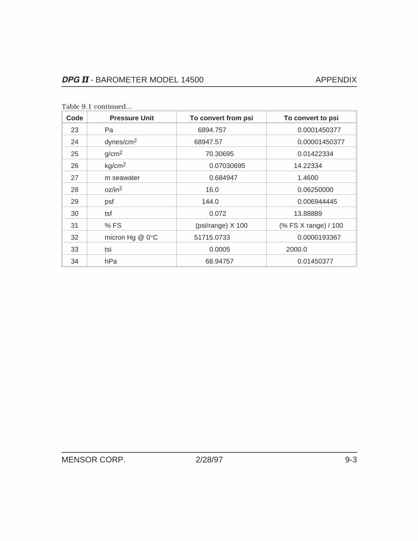
Table 9.1 continued...
Code Pressure Unit To convert from psi To convert to psi
23 Pa 6894.757 0.0001450377
24 dynes/cm2 68947.57 0.00001450377
25 g/cm2 70.30695 0.01422334
26 kg/cm2 0.07030695 14.22334
27 m seawater 0.684947 1.4600
28 oz/in2 16.0 0.06250000
29 psf 144.0 0.006944445
30 tsf 0.072 13.88889
31 % FS (psi/range) X 100 (% FS X range) / 100
32 micron Hg @ 0°C 51715.0733 0.0000193367
33 tsi 0.0005 2000.0
34 hPa 68.94757 0.01450377
DPG II - BAROMETER MODEL 14500 APPENDIX
MENSOR CORP. 2/28/97 9-3

CONVERSION FACTORS, MILLITORR
The following table lists conversion factors which should be used as multipliersof the pressure to be converted to or from millitorr.
Table 9.2 – Conversion Factors, millitorr
Code Pressure Unit To convert from millitorr To convert to millitorr
1 psi 0.0000193367 51715.1
2 inHg @ 0°C 0.0000393701 25400.0
3 inHg @ 60°F 0.0000394812 25328.5
4 inH2O @ 4°C 0.000535253 1868.27
5 inH2O @ 20°C 0.000536201 1864.97
6 inH2O @ 60°F 0.000535774 1866.5
7 ftH2O @ 4°C 0.0000446045 22419.3
8 ftH2O @ 20°C 0.0000446834 22379.6
9 ftH2O @ 60°F 0.0000446478 22398
10 mtorr 1.0 1.0
11 in seawater 0.000521442 1918
12 ft seawater 0.0000434535 23010
13 atm 0.00000131579 760002
14 bars 0.00000133322 750064
15 mbar 0.00133322 750.064
16 mmH2O @ 4°C 0.0135954 73.5541
17 cmH2O @ 4°C 0.00135954 735.541
18 mH2O @ 4°C 0.0000135954 73554.1
19 mmHg @ 0°C 0.001 1000.00
20 cmHg @ 0°C 0.0001 10000.0
21 torr 0.001 1000.00
22 kPa 0.000133322 7500.64
Continued on next page...
APPENDIX DPG II - BAROMETER MODEL 14500
9-4 2/28/97 MENSOR CORP.

Table 9.2 continued...
Code Pressure Unit To convert from millitorr To convert to millitorr
23 Pa 0.133322 7.50064
24 dynes/cm2 1.33322 0.750064
25 g/cm2 0.00135951 735.561
26 kg/cm2 0.00000135951 735561
27 m seawater 0.0000132446 75500
28 oz/in2 0.000309388 3232.19
29 psf 0.00278449 359.132
30 tsf 0.00000139224 718265
31 % FS (mtorr/range) x 100 (% FS x range) / 100
32 micron Hg @ 0°C 1.0 1.0
33 tsi 0.00000000967 103430147.
34 hPa 0.00133322 750.064
DPG II - BAROMETER MODEL 14500 APPENDIX
MENSOR CORP. 2/28/97 9-5

TEMPERATURE CONVERSION (Table 9.3)
Find the known value in a center (shaded) column. If the known value is in °C thenthe equivalent value is found in the °F column, or if the known value is in °F thenthe conversion is found in the °C column.
-17.78-17.22-16.67-16.11-15.56-15.00-14.44-13.89-13.33-12.78-12.22-11.67-11.11-10.56-10.00-9.44-8.89-8.33-7.78-7.22-6.67-6.11-5.56-5.00-4.44-3.89-3.33-2.78-2.22-1.67-1.11-0.56
-17.78-17.22-16.67-16.11-15.56-15.00-14.44-13.89-13.33-12.78-12.22-11.67-11.11-10.56-10.00-9.44-8.89-8.33-7.78-7.22-6.67-6.11-5.56-5.00-4.44-3.89-3.33-2.78-2.22-1.67-1.11-0.560.000.561.111.672.222.783.333.894.445.005.566.116.677.227.788.338.899.44
0.000.561.111.672.222.783.333.894.445.005.566.116.677.227.788.338.899.44
32.0033.8035.6037.4039.2041.0042.8044.6046.4048.2050.0051.8053.6055.4057.2059.0060.8062.6064.4066.2068.0069.8071.6073.4075.2077.0078.80
32.0033.8035.6037.4039.2041.0042.8044.6046.4048.2050.0051.8053.6055.4057.2059.0060.8062.6064.4066.2068.0069.8071.6073.4075.2077.0078.8080.6082.4084.2086.0087.8089.6091.4093.2095.0096.8098.60100.40102.20104.00105.80107.60109.40111.20113.00114.80116.60118.40120.20
80.6082.4084.2086.0087.8089.6091.4093.2095.0096.8098.60100.40102.20104.00105.80107.60109.40111.20113.00114.80116.60118.40120.20
Co oF Co oF Co oF Co oF10.0010.5611.1111.6712.2212.7813.3313.8914.4415.0015.5616.1116.6717.2217.7818.3318.8919.4420.0020.5621.1121.6722.2222.7823.3323.8924.4425.0025.5626.11
10.0010.5611.1111.6712.2212.7813.3313.8914.4415.0015.5616.1116.6717.2217.7818.3318.8919.4420.0020.5621.1121.6722.2222.7823.3323.8924.4425.0025.5626.1126.6727.2227.7828.3328.8929.4430.0030.5631.1131.6732.2232.7833.3333.8934.4435.0035.5636.1136.6737.22
26.6727.2227.7828.3328.8929.4430.0030.5631.1131.6732.2232.7833.3333.8934.4435.0035.5636.1136.6737.22
122.00123.80125.60127.40129.20131.00132.80134.60136.40138.20140.00141.80143.60145.40147.20149.00150.80152.60154.40156.20158.00159.80161.60
122.00123.80125.60127.40129.20131.00132.80134.60136.40138.20140.00141.80143.60145.40147.20149.00150.80152.60154.40156.20158.00159.80161.60163.40165.20167.00168.80170.60172.40174.20176.00177.80179.60181.40183.20185.00186.80188.60190.40192.20194.00295.80197.60199.40201.20
163.40165.20167.00168.80170.60172.40174.20176.00177.80179.60181.40183.20185.00186.80188.60190.40192.20194.00295.80197.60199.40201.20203.00204.80206.60208.40210.20
203.00204.80206.60208.40210.20
5051525354555657585960616263646566676869707172737475767778798081828384858687888990919293949596979899
37.7838.3338.8939.4440.0040.5641.1141.6742.2242.7843.3343.8944.4445.0045.5646.1146.6747.2247.7848.3348.8949.4450.0050.5651.1151.6752.22
37.7838.3338.8939.4440.0040.5641.1141.6742.2242.7843.3343.8944.4445.0045.5646.1146.6747.2247.7848.3348.8949.4450.0050.5651.1151.6752.2252.7853.3353.8954.4455.0055.5656.1156.6757.2257.7858.3358.8959.4460.0060.5661.1161.6762.2262.7863.3363.8964.4465.00
52.7853.3353.8954.4455.0055.5656.1156.6757.2257.7858.3358.8959.4460.0060.5661.1161.6762.2262.7863.3363.8964.4465.00
212.00213.80215.60217.40219.20221.00222.80224.60226.40228.20230.00231.80233.60235.40237.20239.00240.80242.60244.40246.20248.00249.80
212.00213.80215.60217.40219.20221.00222.80224.60226.40228.20230.00231.80233.60235.40237.20239.00240.80242.60244.40246.20248.00249.80251.60253.40255.20257.00258.80260.60262.40264.20266.00267.80269.60271.40273.20275.00276.80278.60280.40282.20284.00285.80
251.60253.40255.20257.00258.80260.60262.40264.20266.00267.80269.60271.40273.20275.00276.80278.60280.40282.20284.00285.80287.60289.40291.20293.00294.80296.60298.40300.20
287.60289.40291.20293.00294.80296.60298.40300.20
100101102103104105106107108109110111112113114115116117118119120121122123124125126127128129130131132133134135136137138139140141142143144145146147148149
65.5666.1166.6767.2267.7868.3368.8969.4470.0070.5671.1171.6772.2272.7873.3373.8974.4475.0075.5676.1176.6777.2277.7878.3378.9979.4480.00
65.5666.1166.6767.2267.7868.3368.8969.4470.0070.5671.1171.6772.2272.7873.3373.8974.4475.0075.5676.1176.6777.2277.7878.3378.9979.4480.0080.5681.1181.6782.2282.7883.3383.8984.4485.0085.5686.1186.6787.2287.7888.3388.8989.4490.0090.5691.1191.6792.2292.78
80.5681.1181.6782.2282.7883.3383.8984.4485.0085.5686.1186.6787.2287.7888.3388.8989.4490.0090.5691.1191.6792.2292.78
302.00303.80305.60307.40309.20311.00312.80314.60316.40318.20320.00321.80323.60325.40327.20329.00330.80332.60334.40
302.00303.80305.60307.40309.20311.00312.80314.60316.40318.20320.00321.80323.60325.40327.20329.00330.80332.60334.40336.20338.00339.80341.60343.40345.20347.00348.80350.60352.40354.20356.00357.80359.60361.40363.20365.00366.80368.60
336.20338.00339.80341.60343.40345.20347.00348.80350.60352.40354.20356.00357.80359.60361.40363.20365.00366.80368.60370.40372.20374.00375.80377.60379.40381.20383.00384.80386.60388.40390.20
370.40372.20374.00375.80377.60379.40381.20383.00384.80386.60388.40390.20
150151152153154155156157158159160161162163164165166167168169170171172173174175176177178179180181182183184185186187188189190191192193194195196197198199
012345678910111213141516171819202122232425262728293031323334353637383940414243444546474849
APPENDIX DPG II - BAROMETER MODEL 14500
9-6 2/28/97 MENSOR CORP.

MATERIALS IN CONTACT WITH PRESSURE MEDIUM
The recommended pressure medium is clean, dry, non-corrosive gases. ConsultMensor Corporation for applications requiring liquid-filled pressure sensors.
Table 9.4 – Materials In Contact With Pressure Medium
Materials in contact with Pressure Medium
Metallics Non-MetallicsAluminum Buna-N RubberBrass Silicon
Silicone GreaseEpoxyPolyester
DPG II - BAROMETER MODEL 14500 APPENDIX
MENSOR CORP. 2/28/97 9-7

HEAD PRESSURE CORRECTION
The accuracy of pressure measurement depends on several factors, one of whichis the consideration of the head pressure in the system. The pressure medium,whether a gas or liquid, can cause an error in the measurement if not considered.In some cases the offset may be insignificant, and it may be ignored. The followinginformation provides instructions for determining the density of the pressuremedium and how to calculate the head pressure effect.
Gas DensityLiquids and gases have mass and are affected by gravity. The extent of the effectis dependent upon the density of the pressure medium. Liquids normally havea constant density that does not change with pressure. Gases however, increasein density as the pressure increases. To determine the density of a gas at a specificpressure multiply the absolute pressure by the density from the following table.For gas the head pressure difference due to temperature changes within thecompensated temperature range will be insignificant.
Table 9.5 – Gas Density
Gas @ 23°C Density per psi in pounds/in3(Dpsi)
Air,Dry 2.9315 X 10⁻⁶
Argon (A) 4.0443 X 10⁻⁶
Carbon Dioxide (CO2) 4.4824 X 10⁻⁶
Helium (He) 4.0466 X 10⁻⁷
Hydrogen (H2) 2.0379 X 10⁻⁷
Nitrogen (N2) 2.8355 X 10⁻⁶
APPENDIX DPG II - BAROMETER MODEL 14500
9-8 2/28/97 MENSOR CORP.
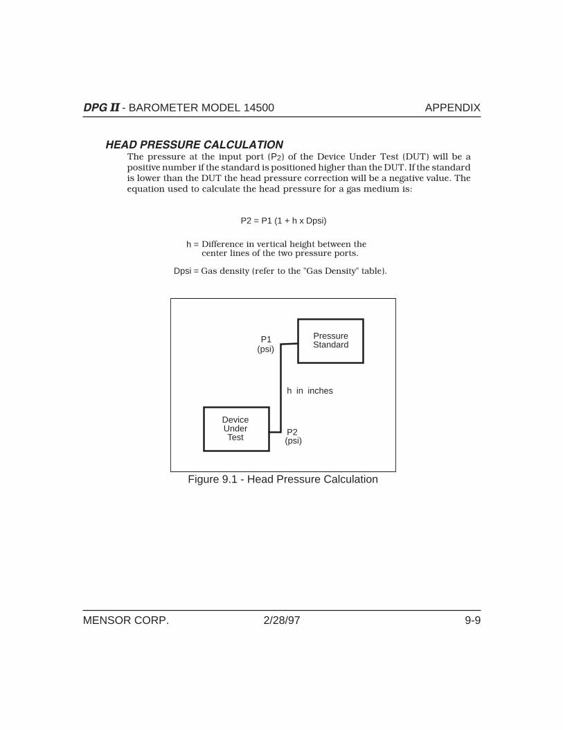
HEAD PRESSURE CALCULATIONThe pressure at the input port (P2) of the Device Under Test (DUT) will be apositive number if the standard is positioned higher than the DUT. If the standardis lower than the DUT the head pressure correction will be a negative value. Theequation used to calculate the head pressure for a gas medium is:
PressureStandard
DeviceUnderTest
P1(psi)
P2(psi)
h in inches
P2 = P1 (1 + h x Dpsi)
Difference in vertical height between thecenter lines of the two pressure ports.
h =
Dpsi = Gas density (refer to the "Gas Density" table).
Figure 9.1 - Head Pressure Calculation
DPG II - BAROMETER MODEL 14500 APPENDIX
MENSOR CORP. 2/28/97 9-9

TABLE 9.6 – STANDARD SEA LEVEL PRESSURE AT VARIOUS ELEVATIONS
APPENDIX DPG II - BAROMETER MODEL 14500
9-10 2/28/97 MENSOR CORP.
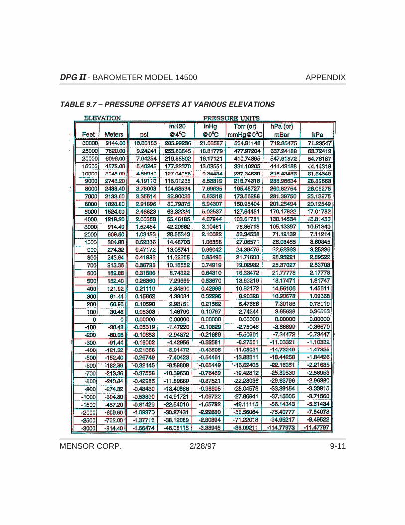
TABLE 9.7 – PRESSURE OFFSETS AT VARIOUS ELEVATIONS
DPG II - BAROMETER MODEL 14500 APPENDIX
MENSOR CORP. 2/28/97 9-11

TABLE 9.8 – CHASSIS DIP SWITCHES (Reference Figure 2.1)
S2 Rear Panel
Functions andGPIB Addresses
S3 Main oard
Tests andSpan Select
S Main oard
Resolution andUnits Select
APPENDIX DPG II - BAROMETER MODEL 14500
9-12 2/28/97 MENSOR CORP.

EIA-232 CABLE CONNECTIONS
Connections for operation with handshaking:
Connections for operation without handshaking:
Figure 9.2 - EIA-232 Cable Connections
DPG II - BAROMETER MODEL 14500 APPENDIX
MENSOR CORP. 2/28/97 9-13

QUICK REFERENCE LIST OF COMMANDS
Table 9.9. – Quick Reference List of Commands
COMMAND REF PAGES QUERY REF PAGES
C 5-11
D (same as T) 5-11
DEFAULT 5-5
DIGITS 5-5 DIGITS? 5-5
DISPLAY 5-5 DISPLAY? 5-5
DOC? 5-5
E 5-11 ERROR? 5-6
FILTER 5-6 FILTER? 5-6
ID? 5-6
MASTER_CAL_ENABLE 5-6
OPT? 5-6
Q 5-12, 5-13
RANGENEG? 5-7
RANGEPOS? 5-7
S 5-14
SEA_LEVEL_ENABLE 5-7
SEA_LEVEL 5-7 SEA_LEVEL? 5-7
SPAN 5-8 SPAN? 5-8
T 5-11
TARE_CAL_ENABLE 5-9
TARE 5-9 TARE? 5-9
TYPE? 5-9Continued on next page...
APPENDIX DPG II - BAROMETER MODEL 14500
9-14 2/28/97 MENSOR CORP.
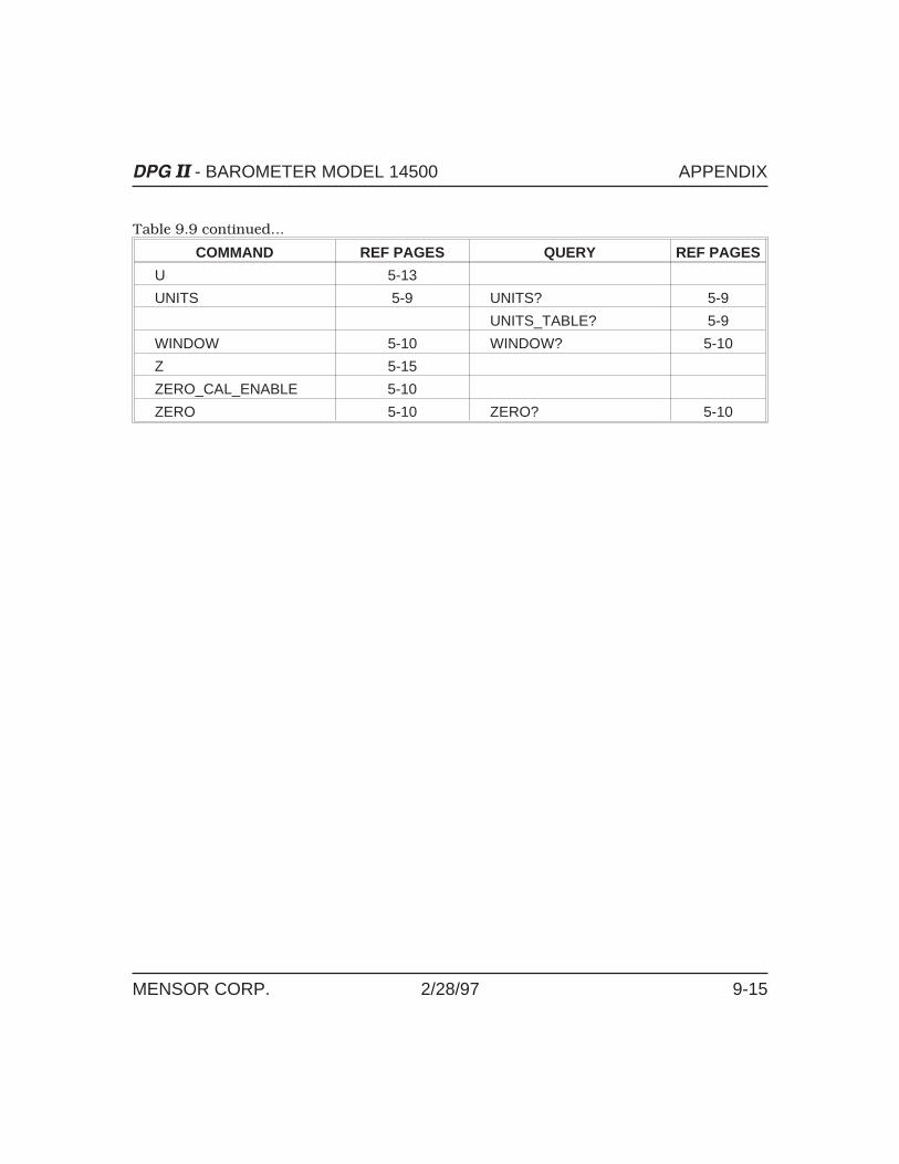
Table 9.9 continued...
COMMAND REF PAGES QUERY REF PAGES
U 5-13
UNITS 5-9 UNITS? 5-9
UNITS_TABLE? 5-9
WINDOW 5-10 WINDOW? 5-10
Z 5-15
ZERO_CAL_ENABLE 5-10
ZERO 5-10 ZERO? 5-10
DPG II - BAROMETER MODEL 14500 APPENDIX
MENSOR CORP. 2/28/97 9-15

SAMPLE IEEE PROGRAM
The following is a sample program in Microsoft QuickBASIC that will read theDPG II output over the IEEE bus:
‘ **********************************************************************‘ GENERAL PROGRAM DESCRIPTION
‘ This program demonstrates functions of the DPG-II’s IEEE commands.‘ IEEE address 3 is for the DPG-II under test. This program uses the‘ National Instruments GPIB drivers. ‘**********************************************************************
‘this file has the IEEE driver calls for Nat. Inst. software‘$INCLUDE: ‘QBDECL4.BAS’
CLS
‘ * * * * * * * * INITIALIZE EQUIPMENT * * * * * * * * * *
‘ ASSUMES CONTROLLER BOARD 0 IS USEDBDNAME$ = “GPIB0"CALL IBFIND(BDNAME$, BRD0%)IF BRD0% < 0 THEN PRINT ”GPIB0 INITIALIZATION ERROR": STOP
‘ ASSUMES DPG-II WITH GPIB ADDR. #3BDNAME$ = “DEV3": CALL IBFIND(BDNAME$, BRD3%)IF BRD3% < 0 THEN PRINT ”DPG-II INITIALIZATION ERROR": STOP
‘ * * * * * * * * SET UP DPG-II * * * * * * * *
‘Set output to be psi, standard outputCALL IBWRT(BRD3%, “Q0X”)CALL IBWRT(BRD3%, “U1X”)
‘This program section reads the range and units from the DPG‘and prints it to the screenCALL IBWRT(BRD3%, “Q3X”)RD$ = SPACE$(50)CALL IBRD(BRD3%, RD$)PRINT RD$
APPENDIX DPG II - BAROMETER MODEL 14500
9-16 2/28/97 MENSOR CORP.

‘Now make 100 readings,1 second apart and store elapsed time‘and the reading to disk
‘Starting timer - note that this rolls over at midnightSTART! = TIMER
FOR I = 1 TO 100NOW! = TIMER: DO: LOOP UNTIL TIMER > NOW! + 1‘1 sec delayRD$ = SPACE$(30): CALL IBRD(BRD3%, RD$)
‘This strips off the carraige return and line‘feed from the DPG string, one could have also
‘returned VAL(RD$) to do math on the DPG output.DPG$ = LEFT$(RD$, 7)
PRINT TIMER - START!; “ ”; DPG$OPEN “A:TESTDATA.PRN” FOR APPEND AS #1
PRINT #1, TIMER - START!; “ ”; DPG$CLOSE #1
NEXT
SYSTEM
DPG II - BAROMETER MODEL 14500 APPENDIX
MENSOR CORP. 2/28/97 9-17

User's Notes:
APPENDIX DPG II - BAROMETER MODEL 14500
9-18 2/28/97 MENSOR CORP.


![EquationsandNomogramfortheRelationshipofHumanBloodP50to · PDF filediphosphoglycerate (2,3-DPG)fortheestimationofp50.Only molarratiosof[2,3-DPG]to[Hb4]oflessthan1wereinves-tigatedinthispreliminarywork;however,itisnowknownthat](https://static.fdocuments.in/doc/165x107/5aa272f17f8b9ac67a8d16e5/equationsandnomogramfortherelationshipofhumanbloodp50to-23-dpgfortheestimationofp50only.jpg)