OPERATION MANUAL CWF-50A Cold Wire Feeder - Welding …
27
OM-CWF-50A-01-2015 2-5-V February 2015 Read this manual carefully before installing, Commissioning, or operating this product. Jetline Engineering, 15 Goodyear Street, Irvine, CA 92618 Telephone: (949) 951-1515 Fax: (949) 951-9237 Web site: www.jetline.com E-mail: [email protected] OPERATION MANUAL CWF-50A Cold Wire Feeder IMPORTANT
Transcript of OPERATION MANUAL CWF-50A Cold Wire Feeder - Welding …

OM-CWF-50A-01-2015
2-5-V
February 2015
Read this manual carefully before installing,
Commissioning, or operating this product.
Jetline Engineering, 15 Goodyear Street, Irvine, CA 92618
Telephone: (949) 951-1515 Fax: (949) 951-9237 Web site: www.jetline.com E-mail: [email protected]
OPERATION MANUAL CWF-50A
Cold Wire Feeder
IMPORTANT


Jetline Engineering, of Irvine, California, U.S.A., warrants all new equipment to be free from defects
in material and workmanship for the period of one (1) year, provided that the equipment is installed and
operated according to instructions.
Jetline Engineering's obligation under this warranty is expressly limited to replacing or repairing any
defective part or correcting any manufacturing defect without charge during the warranty period, if Jetline's
inspection confirms the existence of such defects. Jetline's option of repair or replacement will be F.O.B.
factory at Irvine, California, and therefore no compensation for transportation costs of any kind will be
allowed.
The warranty period begins on the date of sale to the original-purchase user of the equipment.
Jetline Engineering, will not be liable for any loss or consequential damage or expense accruing
directly or indirectly from the use of equipment covered by this warranty.
This warranty supersedes all previous Jetline warranties and is exclusive with no other guarantees or
warranties expressed or implied.
When contacting the factory, please have the serial number and job number of your machine
available in order to reference the original factory configuration.
LIMITED WARRANTY

The installation, operation and maintenance guidelines set out in this manual will enable you to
maintain the equipment in peak condition and achieve maximum efficiency with your welding operation.
Please read these instructions carefully to become aware of every advantage.
Only experienced personnel familiar with
the operation and safe practice of welding
equipment should install and/or use this
equipment.
NOTICE
CAUTION

Table of Contents
Section I ........................................................................................................................................... 1 Safety Precautions ......................................................................................................................... 1
A. Arc Welding ....................................................................................................................... 1
B. Electric Shock ................................................................................................................... 1
C. Arc Rays ............................................................................................................................ 1 D. Fumes and Gases ............................................................................................................ 2
E. Cylinders ............................................................................................................................ 2
F. Welding .............................................................................................................................. 2 G. Moving Parts ..................................................................................................................... 3
H. EMF Information ............................................................................................................... 3 I. Principal Safety Standards ................................................................................................. 3
J. California Proposition 65 Warning .................................................................................... 3
Section II Introduction .................................................................................................................... 4
Section III Installation ..................................................................................................................... 6
Section IV Wire Feed Accessory Kits .......................................................................................... 9
Section V Operating Instructions ................................................................................................ 10
A. Preparation for Welding ............................................................................................. 10
B. Operation ....................................................................................................................... 10
C. Wire Guide Positioner ................................................................................................ 11
Section VI Maintenance ............................................................................................................... 12
Section VII Optional Accessories ............................................................................................... 13
A. 607B Spool Cover ........................................................................................................ 13 B. WGP-2ES Motorized Wire Guide Positioner ......................................................... 13
C. WGP-3 Compact Wire Guide Positioner ................................................................ 13
D. CHWS-100 Wire Straightener .................................................................................... 13
Section VIII Parts Lists ................................................................................................................. 14

-1-
Section I
Safety Precautions
A. Arc Welding
Arc Welding can be hazardous. Protect
yourself and others from possible serious
injury or death. Keep children away.
Pacemaker wearers keep away until
consulting your doctor.
In welding, as in most jobs, exposure to certain hazards
occurs. Welding is safe when precautions are taken.
The safety information given below is only a summary
of the more complete safety information that will be
found in the Safety Standards listed at the end of this
section. Read and follow all Safety Standards.
Have all installation, operation, maintenance and repair
work performed only by qualified people.
B. Electric Shock
Touching live electrical parts can cause fatal shocks or
severe burns. The electrode and work circuit is
electrically live whenever the output is on. The input
power circuit and machine internal circuits are also live
when power is on. When using mechanized wire feed,
the wire, wire reel, drive roll housing and all metal parts
touching the welding wire are electrically live.
Incorrectly installed or improperly grounded equipment
is a hazard.
1. Do not touch live electrical parts.
2. Wear dry, hole-free insulating gloves and
appropriate body protection.
3. Disconnect input power before installing or
servicing this equipment. Lockout/tagout input
power according to OSHA 29 CFR 1910.147
(see Safety Standards).
4. Properly install and ground this equipment
according to the operation manual and
national, state and local codes.
5. Always verify the supply ground-check and be
sure that input power cord ground wire is
properly connected to ground terminal in
disconnect box or that cord plug is connected
to a properly grounded receptacle outlet.
6. When making input connections attach proper
grounding conductor first - double-check
connections
.
7. Frequently inspect input power cord for
damage or bare wiring. Replace cord
immediately if damaged - bare wiring can kill.
8. Turn off all equipment when not in use.
9. If earth grounding of the part is required,
ground it directly with a separate cable - do
not use work clamp or work cable.
10. Do not touch electrode if you are in contact
with the work, ground, or another electrode
from a different machine.
11. Use only well-maintained equipment. Repair
or replace damaged parts at once. Maintain
unit according to manual.
12. Wear a safety harness if working above floor
level.
13. Keep all panels and covers securely in place.
14. Clamp work cable with good metal-to-metal
contact to part or worktable as near the weld as
practical.
C. Arc Rays
Arc rays can burn eyes and skin; noise can damage
hearing; flying slag or sparks can injure eyes.
Arc rays from the welding process produce intense
visible and invisible (ultraviolet and infrared) rays that
can burn eyes and skin. Noise from some processes can
damage hearing. Chipping, grinding and weld cooling
throw off pieces of metal or slag.
1. Use approved ear plugs or ear muffs if noise
level is high.
2. Use a welding helmet fitted with a proper
shade of filter to protect your face and eyes
when welding or watching.
3. Wear approved safety glasses with side
shields.
4. Use protective screens or barriers to protect
others from flash and glare; warn others not to
watch the arc.
5. Wear protective clothing made from durable,
flame-resistant material (wool and leather) and

-2-
foot protection where necessary.
D. Fumes and Gases
Fumes and gases can be hazardous to your health.
Welding produces fumes and gases. Breathing these
fumes and gases can be hazardous to your health.
1. Keep your head out of the fumes. Do not
breathe the fumes.
2. If inside, ventilate the area and/or use exhaust
at the arc to remove welding fumes and gases.
3. If ventilation is poor, use an approved air-
supplied respirator.
4. Read the Material Safety Data Sheets (MSDS)
and the manufacturer's instruction for metals,
consumables, coatings, cleaners, and
degreasers.
5. Work in a confined space only if it is well
ventilated, or while wearing an air-supplied
respirator. Always have a trained watch person
nearby.
6. Do not weld in locations near degreasing,
cleaning, or spraying operations. The heat and
rays of the arc can react with vapors to form
highly toxic and irritating gases.
7. Do not weld on coated metals, such as
galvanized, lead or cadmium plated steel,
unless the coating is removed from the weld
area, the area is well ventilated, and if
necessary, while wearing an air-supplied
respirator. The coatings and any metals
containing these elements can give off toxic
fumes if welded.
E. Cylinders
Cylinders can explode if damaged.
Shielding gas cylinders contain gas under high pressure.
If damaged, a cylinder can explode. Since gas cylinders
are normally part of the welding process, be sure to
treat them carefully.
1. Protect compressed gas cylinders from
excessive heat, mechanical shocks, slag, open
flames, sparks, and arcs.
2. Install cylinders in an upright position by
securing to a stationary support or cylinder
rack to prevent falling or tipping.
3. Keep cylinders away from any welding or
other electrical circuits.
4. Never weld on a pressurized cylinder -
explosion will result.
5. Use only correct shielding gas cylinders,
regulators, hoses and fittings designed for the
specific application; maintain them and
associated parts in good condition.
6. Turn face away from valve outlet when
opening cylinder valve.
7. Keep protective cap in place over valve except
when cylinder is in use or connected for use.
8. Read and follow instructions on compressed
gas cylinders, associated equipment, and CGA
publication P-1 listed in Safety Standards.
F. Welding
Welding can cause fire or explosion.
Welding on closed containers, such as tanks, drums, or
pipes, can cause them to blow up. Sparks can fly off
from the welding arc. The flying sparks, hot part, and
hot equipment can cause fires and burns. Accidental
contact of electrode to metal objects can cause sparks,
explosion, overheating, or fire. Check and be sure the
area is safe before doing any welding.
1. Protect yourself and others from flying sparks
and hot metal.
2. Do not weld where flying sparks can strike
flammable material.
3. Remove all flammables within 35 ft (10.7 m)
of the welding arc. If this is not possible,
tightly cover them with approved covers.
4. Be alert that welding sparks and hot materials
from welding can easily go through small
cracks and openings to adjacent areas.
5. Watch for fire, and keep a fire extinguisher
nearby.
6. Do not weld on closed containers such as
tanks, drums, or pipes, unless they are properly
prepared according to AWSF4.1 (see safety
Standards).
7. Connect work cable to the work as close to the
welding area as practical to prevent welding
current traveling long, possibly unknown paths
and causing electric shock and fire hazards.
8. Wear oil-free protective garments such as
leather gloves, heavy shirt, cuffless trousers,
high shoes, and a cap.

-3-
G. Moving Parts
Moving parts, such as fans, rotors, and belts can cut
fingers and hands and catch loose clothing.
1. Keep all doors, panels, covers, and guards
closed and securely in place.
2. Have only qualified people remove guards or
covers for maintenance and troubleshooting as
necessary.
H. EMF Information
Considerations About Welding and the
Effects of Low Frequency Electric and
Magnetic Fields
The following is a quotation from the General
Conclusions Section of the U.S. Congress, Office of
Technology Assessment, Biological Effects of Power
Frequency Electric & Magnetic Fields - Background
Paper, OTA-BP-E-53 (Washington, DC: U.S.
Government Printing Office, May 1989):
".... there is now a very large volume of scientific
findings based on experiments at the cellular level and
from studies with animals and people which clearly
establish that low frequency magnetic fields can
interact with, and produce changes in, biological
systems. While most of this work is of very high
quality, the results are complex. Current scientific
understanding does not yet allow us to interpret the
evidence in a single coherent framework. Even more
frustrating, it does not yet allow us to draw definite
conclusions about questions of possible risk or to offer
clear science-based advice on strategies to minimize or
avoid potential risks."
To reduce magnetic fields in the work place, use the
following procedures:
1. Keep cables close together by twisting or
taping them.
2. Arrange cables to one side and away from the
operator.
3. Do not coil or drape cables around the body.
4. Keep welding power source and cables as far
away as practical.
5. Connect work clamp to part as close to the
weld as possible.
About Pacemakers:
The above procedures are among those also normally
recommended for pacemaker wearers. Consult your
doctor for complete information.
I. Principal Safety Standards
Reference as applicable
Safety in Welding and Cutting, ANSI Standard Z49.1,
from American Welding Society, 550 N.W. LeJeune
Rd, Miami, FL 33126
Safety and Health Standards, OSHA 29 CFR 1910,
from Superintendent of Documents, U.S. Government
Printing Office, Washington, D.C. 20402
National Electric Code, NFPA Standard 70 from
National Fire Protection Association, Batterymarch
Park, Quincy, MA 02269
Recommended Safe Practices for the Preparation for
Welding and Cutting of Containers That Have Held
Hazardous Substances, American Welding Society
Standard AWS F4.1, from American Welding Society,
550 N.W. LeJeune Rd, Miami, FL 33126
Safe Handling of Compressed Gases in Cylinders, CGA
Pamphlet P-1, from Compressed Gas Association, 1235
Jefferson Davis Highway, Suite 501, Arlington, VA
22202
Code for Safety in Welding and Cutting, CSA Standard
W117.2, from Canadian Standards Association,
Standards Sales, 178 Rexdale Boulevard, Rexdale,
Ontario, Canada M9W 1R3
Sales Practices for Occupation and Educational Eye and
Face Protection, ANSI
Standard Z87.1, from American National Standards
Institute, 1430 Broadway, New York, NY 10018
Cutting and Welding Processes, NFPA Standard 51B,
from National Fire Protection Association,
Batterymarch Park, Quincy, MA 02269
J. California Proposition 65 Warning
This product contains chemicals, including lead, known
to the state of California to cause cancer and birth
defects or other reproductive harm. Wash hands after
use. §248224

-4-
Section II Introduction
The cold wire feeder is designed to supply filler metal to the weld puddle in a mechanized
tungsten arc welding or plasma arc welding application. The system will accurately feed
0.020”, 0.030”, 0.035”, 0.045”, 0.062” and 0.093” (0.5 to 2.4 mm) hard and soft wires for
mechanized TIG or plasma welding.
The wire feeder can be mounted as an assembly or the components can be removed from
the mounting plate and installed in a number of positions with respect to each other.
The system consists of a 9700W control, D.C. motor-driven four feed roll assembly, spool
adapter, and a wire guide positioner. The positioner incorporates X-Y-Z movements of the
wire tip. The positioner includes a universal torch mounting bracket.
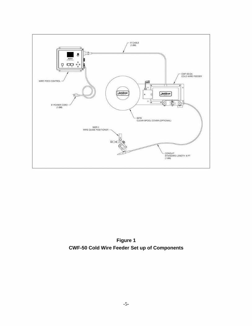
The basic components of the wire feeder are:
(See Figure 1)
1. Wire drive unit: consists of motor, drive housing, and wire spool assembly to feed
wire. (Part number CWF-50-DA.)
2. 9700W Control: includes a keypad, display, encoder control knob, and start/ stop
switches. The SCR motor controller is built into the control box and provides a wire feed
speed of 4 to 200 IPM (10 to 508 CPM) with a speed holding accuracy of +1% of base
speed.
For operating details and function of controls, see 9700W Operation Manual.
3. WGP-1 Wire Guide Positioner: guides wire into puddle.
Note: The wire guide positioner can be used either as a left hand or right hand assembly.
To change configuration as supplied by factory, reverse thumb knob, set screw, and spring.
(See WGP-1 drawing. item numbers 13, 18, and 24.)
4. Spool adapter: holds 12” (305 mm) diameter wire spools.
5. Wire Feed Accessory Kit: conduit, feed rolls, inlet guides, outlet guides, and tips for
0.020”, 0.030”, 0.035”, 0.045”, 0.062” and 0.093” (0.5 to 2.4 mm) hard and soft wire. Order
kits separately for desired wire size.
-5-
Figure 1
CWF-50 Cold Wire Feeder Set up of Components

-6-
Section III Installation
As standard, the unit is provided with 6 ft. (1830 mm) of cable between the control and the
wire drive assembly. The control is typically mounted near the feeder due to the length of
the control cable.
1. To mount the wire drive assembly, transfer mounting holes from the wire feeder’s
aluminum mounting plate to the mounting surface. (See Figure 2 for mounting hole
dimensions.)
2. The 9700W control must be mounted in a suitable manner providing adequate
ventilation. The control should not be mounted in a high temperature environment.
3. Slip the wire guide positioner onto the torch barrel and tighten the wing nuts. You
may choose from one of three sets of mounting holes depending upon the brand of the
torch to be used.
The wire guide tip angle should be set roughly by positioning the guide and tightening the
screw. The tip should be approximately on the same level as the tungsten.
4. Select the wire feed accessory kit for the size wire your application requires. The kit
will include inlet and outlet guides, conduit, wire guide tip, and feed rolls. Be sure all
components match the wire size to be used. (Refer to Figure 3)
Proper installation of the wire feed kit is very critical to the successful operation of the cold
wire feed unit. Proper installation helps avoid “bird-nesting” at the feed rolls and smooth
wire feed delivery into the weld puddle.
a. The inlet guide should be inserted until the “set screw” properly aligns with the
notched section on the guide. The closer the tapered tip is to the feed rolls the better.
b. The intermediate guide needs to be inserted prior to the mounting of the feed
rollers. The intermediate guide also has a “notched” section which should align with the
screw holding it in position.
c. The feed rolls need to be mounted securely. If not tightened, they will loosen and
will eventually fall off.
d. The conduit assembly is then fitted into the outlet guide assembly. This step may
need to be repeated in order to fit it correctly. First, the end and inside of the conduit must
be deburred. The wire must slide freely into the conduit.
Next the conduit should be chamfered. The conduit needs to be as close as possible
to the feed rolls in order to avoid “bird-nesting”, especially on soft wires. Putting a chamfer
on the conduit allows you to get the conduit very close to the feed rolls.

-7-
At this point, slide the conduit through the outlet guide. You should extend the
conduit beyond the tapered end of the outlet guide approximately 1/4” (6 mm). Tighten the
set screw securely, holding the conduit properly in position.
e. Insert the outlet guide/conduit assembly into the drive roll assembly. Position it
so the chamfered conduit is very close to the drive rolls. (Make sure the end of the outlet
guide is clear of the drive rolls.) Tighten the outlet guide securely by turning the hand knob.
f. Run the conduit to the torch as required. Remember sharp twists and turns
affect the flow of the wire. Test the path of the conduit with the torch in its fully retracted
and extended positions.
If the conduit is too long, cut the end, making sure it is completely deburred.
g. Strip 4” (100 mm) of the outer cover on the conduit. Slide the bare conduit into
the wire guide tip. Tighten the set screw holding the conduit securely into position.
Note: On a rare occasion, you may have to pull this end of the conduit from the tip
when initially feeding wire. Let the wire extend about 6” to 8” (150 to 200 mm)
beyond the conduit and then feed the wire into the tip until the conduit is back into
normal position.
The wire guide tip is held in position by a set screw. The tip can slide into the
clamping mechanism on the WGP-1 Wire Guide Positioner.
5. Electrical Connections:
As standard, the feeder is shipped with an electrical connector and 6 ft. (1380 mm)
cord suitable for 115 volts 50/60 Hz power supply. Operation for 220 volts is configurable.
If you need to start the wire feeder from a remote signal, you must supply a normally
open, maintained contact closure to Connector S2, Pins A and B.

-8-
Figure 2
Mounting Plate Dimensions

-9-
Section IV Wire Feed Accessory Kits
Wire Size *Complete
Accessory
Kit
Conduit - 6
ft (2 m)
Outlet
Guide
Inlet Guide Wire Guide
Tip
Feed Rolls
& Inlet
Guide
**Curved
Wire Guide
Tip
0.020”
(0.5 mm)
20B6020K 42-23
PT-40-
NAT
OG-020 056192 WGT-020 053693 N/A
0.030”
(0.8 mm)
20B6030K 44N3545 OG-035-45 056192 WFT-030 046780 CWGT-030
0.035”
(0.9/1 mm)
20B6035K 44N3545 OG-035-45 056192 WGT-035 046781 CWGT-035
0.045”
(1.2 mm)
20B6045K 44N3545 OG-035-45 056193 WGT-045 046782 CWGT-045
0.062”
(1.6 mm)
20B6062K 45N116 OG-062 056195 WGT-062 046784 N/A
0.093”
(2.4 mm)
20B6093K 18630F OG-17 056196 WGT-093 046789 N/A
*Includes inlet and outlet guides, feed rolls, wire guide tip, and 6 ft (2 m) conduit.
**Requires WGP-3 wire guide positioner for curved tips.
Wire Feed Roll Kits, parts and optional items are sold separately.
Figure 3 – Wire Drive Components
-10-
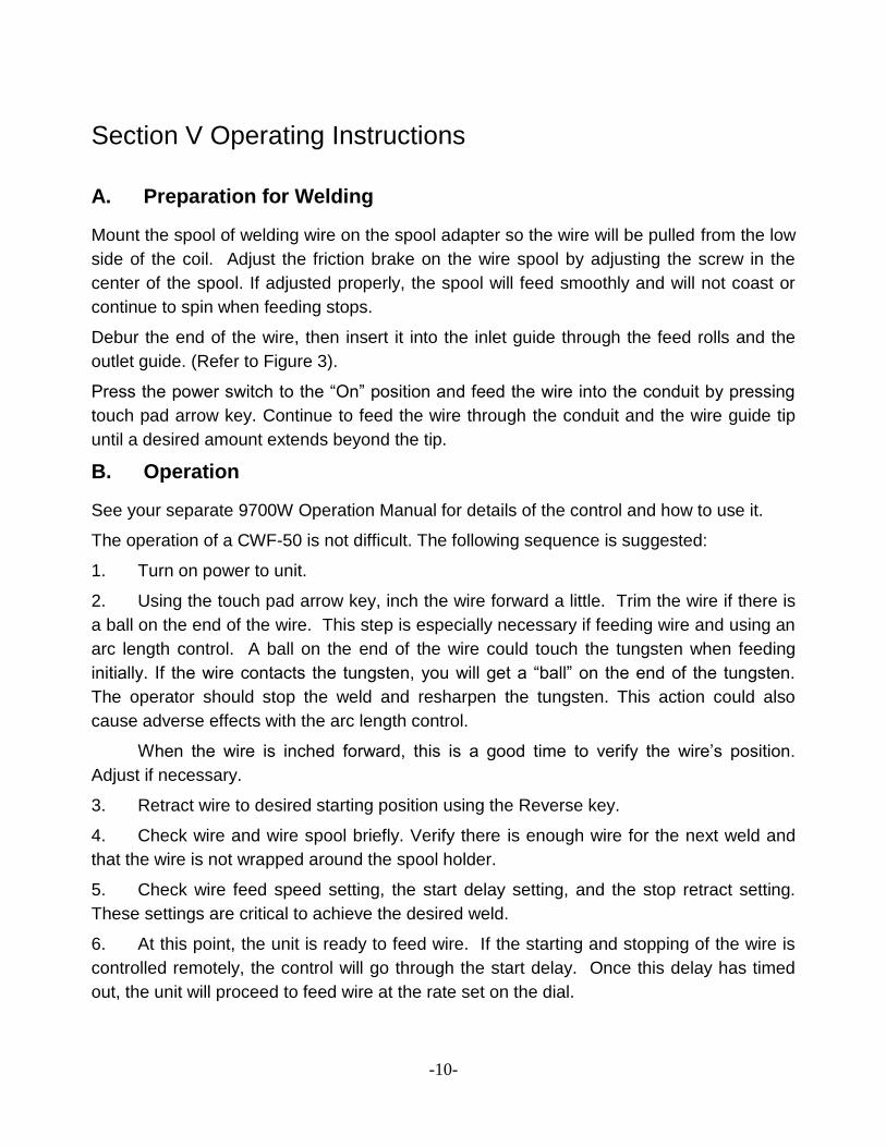
Section V Operating Instructions
A. Preparation for Welding
Mount the spool of welding wire on the spool adapter so the wire will be pulled from the low
side of the coil. Adjust the friction brake on the wire spool by adjusting the screw in the
center of the spool. If adjusted properly, the spool will feed smoothly and will not coast or
continue to spin when feeding stops.
Debur the end of the wire, then insert it into the inlet guide through the feed rolls and the
outlet guide. (Refer to Figure 3).
Press the power switch to the “On” position and feed the wire into the conduit by pressing
touch pad arrow key. Continue to feed the wire through the conduit and the wire guide tip
until a desired amount extends beyond the tip.
B. Operation
See your separate 9700W Operation Manual for details of the control and how to use it.
The operation of a CWF-50 is not difficult. The following sequence is suggested:
1. Turn on power to unit.
2. Using the touch pad arrow key, inch the wire forward a little. Trim the wire if there is
a ball on the end of the wire. This step is especially necessary if feeding wire and using an
arc length control. A ball on the end of the wire could touch the tungsten when feeding
initially. If the wire contacts the tungsten, you will get a “ball” on the end of the tungsten.
The operator should stop the weld and resharpen the tungsten. This action could also
cause adverse effects with the arc length control.
When the wire is inched forward, this is a good time to verify the wire’s position.
Adjust if necessary.
3. Retract wire to desired starting position using the Reverse key.
4. Check wire and wire spool briefly. Verify there is enough wire for the next weld and
that the wire is not wrapped around the spool holder.
5. Check wire feed speed setting, the start delay setting, and the stop retract setting.
These settings are critical to achieve the desired weld.
6. At this point, the unit is ready to feed wire. If the starting and stopping of the wire is
controlled remotely, the control will go through the start delay. Once this delay has timed
out, the unit will proceed to feed wire at the rate set on the dial.

-11-
When the remote start signal quits, the unit will go through the stop delay, then stop.
The unit then proceeds to enter the wire retract time, pulling the wire out of the weld zone.
This action prevents the wire from sticking in the weld puddle at the end of the weld.
Note: If the retract time is set too long, the wire could retract up into the wire tip. If this
happens, the wire could, on occasion, get stuck on the tip on the next weld.
7. If the unit is used manually, the operator will press the Start button when ready to
feed wire. The start delay will NOT be activated when using this method. Wire will feed
immediately once in the Run position.
When wire is no longer required the operator presses the Stop button. The unit will
stop feeding wire immediately and go into the wire retract procedure.
C. Wire Guide Positioner
Several adjustments are provided on the wire guide positioner in order to permit the exact
position of the wire as it enters the puddle.
1. Lateral adjustment of 1/4” (1/8” adjustment of tip on each side of weld seam). (6.4
mm total adjustment, 3.2 mm on each side.)
2. Vertical adjustment of 1/4” (6.4 mm) tip to work.
3. Coarse adjustment of guide tip angle, by loosening screw and setting in approximate
position.
The wire position should be checked at the beginning of the weld.
Jog the wire forward through the control and make required adjustments on the positioner.
Wire typically enters the weld puddle at the leading edge of the puddle. The wire should
contact the work piece about .04” (1 mm) in front of the weld puddle and slide under the
center of the welding arc.
Check tension of drive roll spring. Too much pressure will deform the wire and too
little pressure will cause wire slippage.

-12-
Section VI Maintenance
Periodically clean the drive rolls of dirt and chips. Occasionally check the wear of liners,
tips, and guides.
Periodically check, and replace if necessary, the carbon brushes on the motor. Failure to
replace worn brushes could cause severe damage to motor control.
Maintenance and electrical work must be performed by experienced and trained
personnel.
Whenever repairs are required, always turn all power controls off and disconnect all
electrical cables from power supply.

-13-
Section VII Optional Accessories
When you purchased your cold wire feeder, you may not have been aware of optional
enhancements for your unit. Jetline is pleased to offer these enhancements which can be
added to your system in the field.
If you are interested in these features, please do not hesitate to contact Jetline directly or
the nearest distributor for more information.
A. 607B Spool Cover
The 607B is a clear plastic cover designed and manufactured for Jetline’s wire feeders. The
cover mounts around the spool holder and encases the standard “30 lb/12 inch” wire spool
which fits onto the spool mounting adaptor. The main purpose of the cover is to protect the
wire from dust and weld particle build-up. The clear plastic allows the operator to see the
spool effectively. Installing the spool cover is a simple, perhaps 5 minute, job.
B. WGP-2ES Motorized Wire Guide Positioner
The standard wire feed unit is provided with a manually adjusted WGP-1 wire guide
positioner. In some applications, the operator cannot easily get to the positioner to make
the desired alterations to the wire’s location as it enters the weld puddle. Due to the cast
and helix in some wires, the need to adjust the wire’s position can be required.
Jetline offers the WGP-2ES motorized positioner so the operator can adjust the position of
the wire from a remote location. The positioner includes the motorized wire positioner, the
motor control, and a joystick pendant which the operator uses to move the wire guide tip to
the desired position. Speed of motion is adjustable to provide accurate positioning as
desired by the operator.
C. WGP-3 Compact Wire Guide Positioner
In some applications, the space envelope required by the standard WGP-1 is too large.
Jetline manufactures a wire guide positioner which requires less space, yet still gives the
operator the ability to adjust the wire position. The WGP-3 is designed to attach directly to
the torch, but includes a curved wire guide tip. Wire is fed vertically until the moment where
it is angled into the weld puddle.
D. CHWS-100 Wire Straightener
In some applications, minor deviations in wire position are a result of the cast in the wire.
The wire straightener can help limit the twist by using a 3 roll action. Tension on the center
roll is adjustable. The unit mounts on the inlet side of the drive roll assembly. The
straightener is designed to work on 0.035” and 0.045” (0.9/1.0 and 1.2 mm) wire.

-14-
Section VIII Parts Lists
The following pages provide a detailed parts list of all the elements of the cold wire feed
unit. Item numbers shown in the parts list refer to those numbers contained in the balloons
in the drawing. On each parts list, the quantities shown are the number of items used in
that particular assembly.
Two columns are included in the list to show the spare parts which are recommended to be
stocked by the user. The two levels can be defined as follows:
Level 1
These are the spares recommended for US domestic users whose use of the product does
not exceed 2000 hours per year.
Level 2
These are the spares recommended for international use of the product or for US domestic
users who will use the products in excess of 2000 hours per year.
The following parts lists are included in this manual.
Cold Wire Feeder Assembly
WGP-1 Wire Guide Positioner
WGP-2ES Wire Guide Positioner
WGP-3 Wire Guide Positioner

-15-

-16-
CWF-50-DA
Cold Wire Feeder Assembly
Recommended
Item Part Level Level
No. No. Description Qty I II
2 CWF-20B-100 Mounting Plate .........................................................1
3 CWF-20B-110 Mounting Bracket ....................................................1
4 CWF-20B-120 Cover Assembly .......................................................1
5 Drive Housing, includes: .........................................1
046779 Housing ....................................................................1
053842 Gear ..........................................................................4 2
10-32x7/8 Flat Head Screw .....................................................12
1/2-20x1 1/4 Hex Head Screw ......................................................4
6 0467__ Gear Driven Roll Kit ................................................1
(See chart in Section V for complete part number)
7 OG-030/045 Outlet Guide (See chart in Section V) .....................1
8 44N3545 Conduit and Liner (See chart in Section V) .............1
9 WGT-0__ Wire Guide Tip ........................................................1
(See chart in Section V for complete part number)
10 CWF-10-WG-60 Gear Reducer ...........................................................1
11 95611AO31 Insulating Washer ....................................................1
12 8527K134 Insulating Tube, 36” (914 mm) length .....................1
13 Natural Hard Fiber Insulation ..................................2
14 Natural Hard Fiber Insulation ..................................2
15 053841 Drive Gear ................................................................1 1
16 374831-A Spool Adapter ..........................................................1
17 MT3353-42CZ Motor, DC Servo, with flange..................................1
18 6010 Shielded Cable, 8 ft (2.5 m) .....................................1
19 3106A-145-6P Cable Connection .....................................................1
20 CWF-10-4R-9 Set Screw Collar ......................................................1
21 CWF-20B-140 Retainer ....................................................................1
22 8-32X5/8 Socket Head Screw ..................................................1
23 8-32X5/16 Button Head Screw ..................................................4
24 1/4-20X1/2 Socket Head Screw ..................................................4
25 1/4-20X5/8 Flat Head Screw .......................................................4
26 3/8-16X1 1/4 Hex Head Screw ......................................................2
27 3/8 Flat Washer ..............................................................2

-17-

-18-
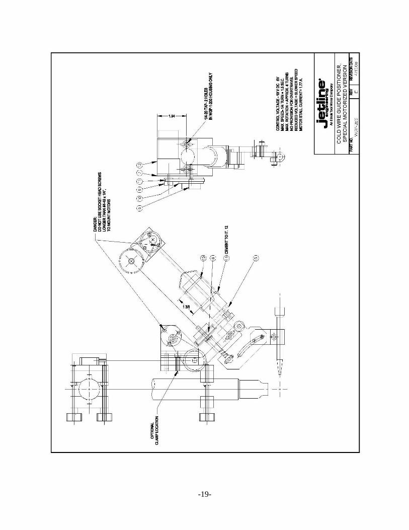
WGP-1 (Rev L)
Wire Guide Positioner
Recommended
Item Part Level Level
No. No. Description Qty I II
2 WGP-1-230 Base ..........................................................................1
3 WGP-1-100 (REV E) Cam Plate .................................................................1
4 WGP-1-200 Housing ....................................................................1
5 WGP-1-210 (REV E) Bar ............................................................................1
6 WGP-1-220 Clamp .......................................................................1
7 WGP-XXX Shown for Reference (part of Wire Feed Kit)
8 WGP-1-240 Stud ..........................................................................2
9 WGP-1-250 V-Block ....................................................................2 1
10 Guide, Dowell ..........................................................1
11 Fulcrum Pin, Dowell ................................................1
12 Hinge Pin, Dowell ....................................................1
13 CL-1-KHS Knurled Head Screw ................................................1 1 1
14 CL-1-KN Knurled Nut .............................................................1 1 1
15 CL-1-SB Swing Bolt ...............................................................1
16 WGP-1-16 Lift Pin .....................................................................1
17 6655K13 Thrust Bearing .........................................................1
18 VV-38 Compression Spring .................................................1 1
19 1/4-20x7/8 Socket Head Screw ..................................................2
20 1/4-20x5/8 Socket Head Screw ..................................................2 2 2
21 1/4 Flat Washer ..............................................................1
22 11256 Compression Spring .................................................1 1
23 3025 Knob .........................................................................2 1 1
24 3/8-16-5/16 Nylock Set Screw .....................................................1
25 WGP-1-260 V-Mount (Optional Item, Large Clamp Kit)............1
26 WGP-1-261 V-Clamp (Optional Item, Large Clamp Kit)............1
27 WGP-1-262 Stud (Optional Item, Large Clamp Kit) ...................2
28 1/4-20-5/8 Socket Head Screw ..................................................2
29 WGP-1-263 Base Extension (Optional Item, extended base) ......1
30 1/4-20x3/4 Socket Head Screw (Optional Item, extended base) ....2
31 6435K12 Collar, 1/4 diameter .................................................1
32 6391K143 Bronze Bearing, 1/4 x 1/2 x 1 ..................................1
-19-

-20-
WGP-2ES (Rev E)
Motorized Wire Guide Positioner
Recommended
Item Part Level Level
No. No. Description Qty I II
2 WGP-1 Basic Wire Guide Assembly ....................................1
5 WGP-2-5 (REV C) Motor Bracket, detail ...............................................1
6 WGP-2-6 Screw........................................................................1
7 WGP-2-7 Motor Bracket, detail ...............................................1
8 WGP-2-10 Driven Pulley, detail ................................................1
9 1375K34 Driven Pulley, detail ................................................2
10 WGP-2-10 Driven Pulley ...........................................................1
11 1679K86 Belt ...........................................................................2 1 1
12 WGP-2-9 Motors and Cable Assembly, set .............................1
13 4-40x1/4 Socket Head Screw ..................................................6
14 DWM-202 Cover ........................................................................2
15 #2-216 O-ring seal ................................................................4
16 9045 Control Assembly, for reference
17 Lift Pin, detail ..........................................................1

-21-

-22-
WGP-3
Compact Wire Guide Positioner
Recommended
Item Part Level Level
No. No. Description Qty I II
2 WGP-3-2 Base Detail ...............................................................1
3 WGP-3-3 Yoke Detail ..............................................................1
4 WGP-3-4 Slide Detail...............................................................1
5 WGP-3-5 Rotor Detail ..............................................................1
6 WGP-1-250 V-Block Detail .........................................................2 1
7 WGP-1-240 Stud ..........................................................................2
8 WGP-3-8 Pin Detail .................................................................1
9 WGP-3-9 Clamp Detail ............................................................1
10 WGP-3-10 Tube Detail...............................................................1
11 WGP-3-11 Spacer Detail ............................................................1
12 Fender Washer .........................................................1
13 XX-68 Compression Pin ......................................................1 1
14 L-35 Compression Pin ......................................................1 1
15 2813 Compression Pin ......................................................1
16 CL-1-KHS Knurled Head Screw ................................................1 1 1
17 CL-6-KHS Knurled Head Screw ................................................1 1 1
18 CL-2-SLB Button, radius loc .....................................................1
19 1/4-20x3/4 Socket Head Screw ..................................................3 2 2
20 1/4 Flat Washer ..............................................................1
21 1/420 Hex Nut ....................................................................1
22 1/4-20x2 1/4 Hex Head Screw ......................................................1
23 1/8x3/4 Roll Pin ....................................................................1
24 CWGT Curved Wire Guide Tip Detail .................................1
25 3025 Knob .........................................................................2 1 1