OPERATION MANUAL - burster
21
OPERATION MANUAL Fieldbus-Controller 9251 EtherCAT Integration into TwinCAT Manufacturer: © 2021 burster praezisionsmesstechnik gmbh & co kg burster präzisionsmesstechnik gmbh & co kg All rights reserved Talstr. 1 - 5 P.O. Box 1432 76593 Gernsbach 76587 Gernsbach Germany Germany Valid from: 01.04.2021 Tel.: +49-7224-645-0 Applies to: 9251-V1X00 Fax.: +49-7224-645-88 Email: [email protected] www.burster.com 4077-BA9251ETHERCATEN-5999-041525
Transcript of OPERATION MANUAL - burster
OPERATION MANUAL
Fieldbus-Controller 9251 EtherCAT Integration into TwinCAT
Manufacturer: © 2021 burster
praezisionsmesstechnik gmbh & co kg burster präzisionsmesstechnik gmbh & co kg
All rights reserved Talstr. 1 - 5 P.O. Box 1432 76593 Gernsbach 76587 Gernsbach Germany Germany Valid from: 01.04.2021 Tel.: +49-7224-645-0 Applies to: 9251-V1X00 Fax.: +49-7224-645-88 Email: [email protected] www.burster.com 4077-BA9251ETHERCATEN-5999-041525
2 of 21
Table of Contents 1 Introduction ................................................................................................................................................ 3
2 Creating new project ................................................................................................................................. 4
3 Installation of ESI description files .......................................................................................................... 6
4 Scan EtherCAT devices ............................................................................................................................ 7
5 Create a sample program ....................................................................................................................... 10
6 Further Examples .................................................................................................................................... 16
6.1 Read and Write of ‘real’ data types .................................................................................................. 16 6.2 Read and Write of ‘string’ data types ............................................................................................... 20

3 of 21
1 Introduction This quick start guide describes an approach how you can configure the 9251 via Beckhoff TwinCAT using a Beckhoff PCI-Ethernet Card. Please note that the samples here cannot be directly used in your production line because they have beed extremely simplified to reach a better understanding. Therefore, you may have to complete them by checking of status, error, length values etc.
Please also note that you will have to use the 9251 manual to get futher information about input and output parameters (cyclic as well acyclic data transfer)

4 of 21
2 Creating new project • Start the TwinCAT XAE Shell and click on New TwinCAT Project (or via File → New Project)
• Select TwinCAT XAE Project, assign a project a name (b) and click OK
a
b

5 of 21
• Go to TwinCAT (a), select Show Real Time Ethernet Compatible Devices… (b) and look for you’re a EtherCAT Master device under Compatible devices (c). Afterwards click the Install button (d).
b
c
a
d
6 of 21
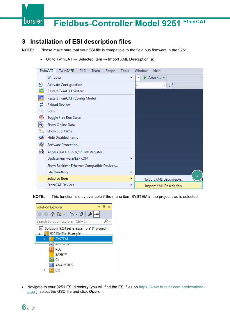
3 Installation of ESI description files NOTE: Please make sure that your ESI file is compatible to the field bus firmware in the 9251.
• Go to TwinCAT → Selected Item → Import XML Description (a)
NOTE: This function is only avaliable if the menu item SYSTEM in the project tree is selected:
• Navigate to your 9251 ESI directory (you will find the ESI files on https://www.burster.com/en/download-area ), select the GSD file and click Open.
a

7 of 21
4 Scan EtherCAT devices • Right click I/O → Devices (a) in the project tree und select Scan (b):
• Now, you can select an EtherCAT compatible device in the new window and click OK:
a
b
8 of 21
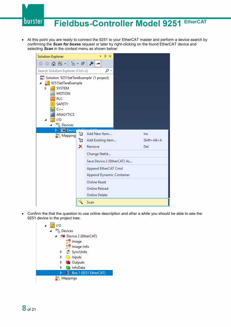
• At this point you are ready to connect the 9251 to your EtherCAT master and perform a device search by confirming the Scan for boxes request or later by right-clicking on the found EtherCAT device and selecting Scan in the context menu as shown below:
• Confirm the that the question to use online description and afrer a while you should be able to see the
9251 device in the project tree:

9 of 21
• To see the process data, please click on the 9251 in the project tree (a) and select the Process Data tab (b):
a
b

10 of 21
5 Create a sample program In this section, you will learn how to create a simple PLC program to execute the tare function via PDO (Process Data Object). You will need to refer to section 7.3 EtherCAT PDO – Process Data Objects in 9251 documentation manual to understand the meaning of input bytes.
• Right-click PLC in the project tree and select Add New Item...
• Select Standard PLC Project (a) in the Add New Item dialog, enter SetTare as project name (b) and
click Add
a
b
11 of 21
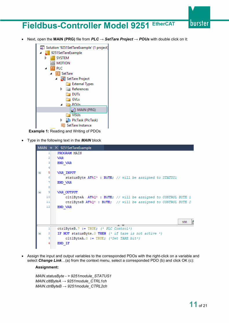
• Next, open the MAIN (PRG) file from PLC → SetTare Project → POUs with double click on it:
Example 1: Reading and Writing of PDOs
• Type in the following text in the MAIN block
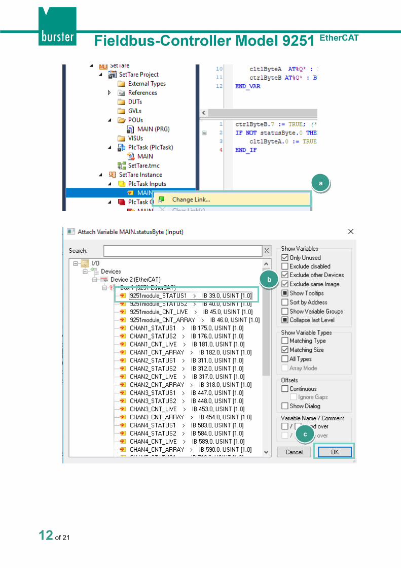
• Assign the input and output variables to the corresponded PDOs with the right-click on a variable and select Change Link…(a) from the context menu, select a corresponded PDO (b) and click OK (c):
Assignment:
MAIN.statusByte - > 9251module_STATUS1 MAIN.cltlByteA → 9251module_CTRL1ch MAIN.ctrlByteB → 9251module_CTRL2ch
12 of 21
a
b
c
13 of 21
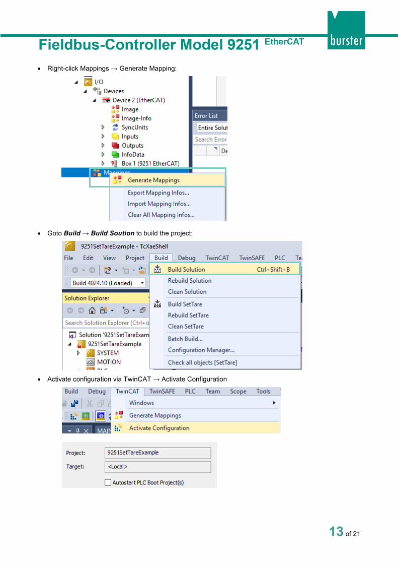
• Right-click Mappings → Generate Mapping:
• Goto Build → Build Soution to build the project:
• Activate configuration via TwinCAT → Activate Configuration
14 of 21
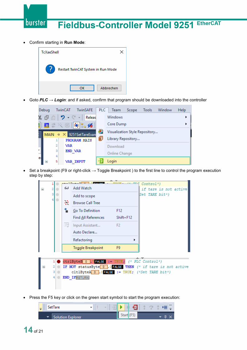
• Confirm starting in Run Mode:
• Goto PLC → Login: and if asked, confirm that program should be downloaded into the controller
• Set a breakpoint (F9 or right-click → Toggle Breakpoint ) to the first line to control the program execution
step by step:
• Press the F5 key or click on the green start symbol to start the program execution:
15 of 21
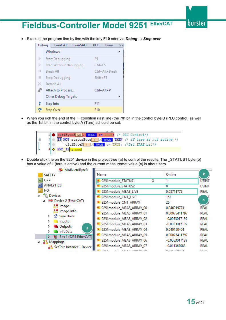
• Execute the program line by line with the key F10 oder via Debug → Step over
• When you rich the end of the IF condition (last line) the 7th bit in the control byte B (PLC control) as well
as the 1st bit in the control byte A (Tare) schould be set:
• Double click the on the 9251 device in the project tree (a) to control the results. The _STATUS1 byte (b)
has a value of 1 (tare is active) and the current measuremet value (c) is about zero
a
b
c
16 of 21
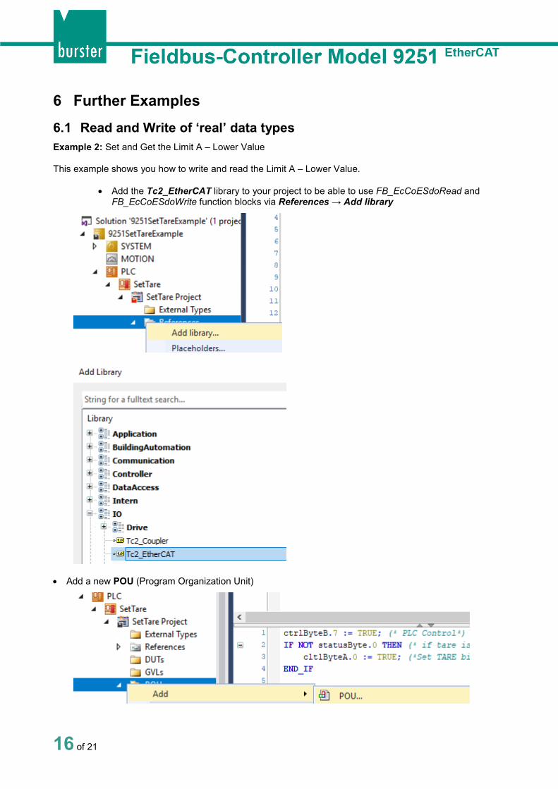
6 Further Examples 6.1 Read and Write of ‘real’ data types Example 2: Set and Get the Limit A – Lower Value
This example shows you how to write and read the Limit A – Lower Value.
• Add the Tc2_EtherCAT library to your project to be able to use FB_EcCoESdoRead and FB_EcCoESdoWrite function blocks via References → Add library
• Add a new POU (Program Organization Unit)

17 of 21
• Rename it to WriteReadLimitALow and click OK:
• Incert the call of the WriteReadLimitALow in the MAIN POU:

18 of 21
• Type in the following code into the created WriteReadLimitALow POU
Source code:
PROGRAM WriteReadLimitALow VAR fbSdoWrite : FB_EcCoESdoWrite; fbSdoRead : FB_EcCoESdoRead; sNetId : T_AmsNetId := '169.254.20.111.3.1'; // see note 1 below nSlaveAddr : UINT := 1001; // see note 2 below nIndex : WORD := 16#206A; // CoE Object - Limit A Lower Value nSubIndex : BYTE := 0; // is always 0 fLimitALow : REAL := 1.43; // data to be written to 9251 bExecute : BOOL := TRUE; bError : BOOL; nErrId : UDINT; END_VAR fbSdoWrite( sNetId := sNetId, nSlaveAddr := nSlaveAddr, nIndex := nIndex, nSubIndex := nSubIndex, pSrcBuf := ADR(fLimitALow), cbBufLen := SIZEOF(fLimitALow), bExecute := bExecute ); IF NOT fbSdoWrite.bBusy THEN bExecute := FALSE; IF NOT bError THEN (* write successful *) bError := FALSE; nErrId := 0; ELSE (* write failed *) bError := fbSdoWrite.bError; nErrId := fbSdoWrite.nErrId; END_IF fbSdoWrite(bExecute := FALSE); END_IF fLimitALow := 0.0; fbSdoRead(sNetId:= sNetId,nSlaveAddr :=nSlaveAddr, nIndex:=nIndex, nSubIndex :=nSubIndex, pDstBuf:= ADR(fLimitALow), cbBufLen:=SIZEOF(fLimitALow), bExecute:=TRUE); bError:=fbSdoRead.bError; nErrId:=fbSdoRead.nErrId;
NOTE: You will find the NetId if you click your EtherCAT master device in the project tree and select the tab EtherCAT:

19 of 21
NOTE: You will find the EtheCAT alave address if you click the 9251 device in the project tree and select the tab EtherCAT:
• Build the project via Build → Build Solution, click on the Login symbol and set a break point (F9) in the first code line:
• Start the program execution with the F5 key or via PLC → Start and go step for step (F10) through the
whole program until you rich the last line. Check if the witten und read values are identical:

20 of 21
6.2 Read and Write of ‘string’ data types Example 3: Read the serial number of 9251:
• Create a new POU as described above and name it ReadSerial:
• Write or copy the following source code into the new POU:
PROGRAM ReadSerial VAR fbSdoRead : FB_EcCoESdoRead; sNetId : T_AmsNetId := '169.254.20.111.3.1'; // see note 1 in the previous section nSlaveAddr : UINT := 1001; // see note 2 in the previous section nIndex : WORD := 16#2073; // CoE Object – Serial number nSubIndex : BYTE := 0; // is always 0 abSerial : STRING; bExecute : BOOL := TRUE; bError : BOOL; nErrId : UDINT; END_VAR fbSdoRead(sNetId:= sNetId, nSlaveAddr :=nSlaveAddr, nIndex:=nIndex, nSubIndex :=nSubIndex, pDstBuf:= ADR(abSerial), cbBufLen:=20, bExecute:=TRUE); bError:=fbSdoRead.bError; nErrId:=fbSdoRead.nErrId;
• Instert a call for the POU in the MAIN block:
• Build the Project via Build → Build Solution:

21 of 21
• Log in PLC → Login, set a break point to the last line and click PLC –> Start (F5) to run the program
• The serial number is read into the variable ‘abSerial’