Operation manual 2003 - PQ RIDEpq-ride.co.kr/dataroom/files/Sepam80.pdf · manual 2003...
84
Sepam Series 80 Installation, use, commissioning and maintenance Electrical network protection Operation manual 2003
Transcript of Operation manual 2003 - PQ RIDEpq-ride.co.kr/dataroom/files/Sepam80.pdf · manual 2003...

Sepam Series 80Installation, use, commissioning and maintenance
Electrical network protection
Operation manual
2003
SEPED303003EN_cover.fm Page 4 Vendredi, 27. juin 2003 7:21 07


1
1
2
3
4
General contents
Installation
Use
Commissioning
Maintenance
SEPED303003EN_TDM.FM Page 1 Lundi, 23. juin 2003 10:46 10

2
SEPED303003EN_TDM.FM Page 2 Lundi, 23. juin 2003 10:46 10

3
1
Installation Contents
Equipment identification 4
Precautions 6
Base unit 7Dimensions 7Mounting 8Connection 9Phase current inputs connection 10Residual current inputs connection 11Phase voltage and residual voltage inputs connection 12
MES120 14 input / 6 output module 14
1 A / 5 A current transformers 16
LPCT type current sensors 18CLP1 sensors 18Test accessories 19
CSH120 and CSH200Core balance CTs 20
CSH30Interposing ring CT 21
ACE990Core balance CT interface 22
Remote modules 24
MET148-2Temperature sensor modules 25
MSA141Analog output module 26
DSM303Remote advanced UMI module 27
Communication accessories 28
Communication protocols and gateways 29
Communication interfaces 30
ACE949-2 2-wire RS 485 network interface 31
ACE9594-wire RS 485 network interface 32
ACE937 Fiber optic interface 33
ACE909-2RS 232 / RS 485 converter 34
ACE919CA and ACE919CCRS 485 / RS 485 converters 36
SEPED303003EN_1-InstallationTDM.fm Page 3 Mardi, 24. juin 2003 2:05 14
4
1
Installation Equipment identification
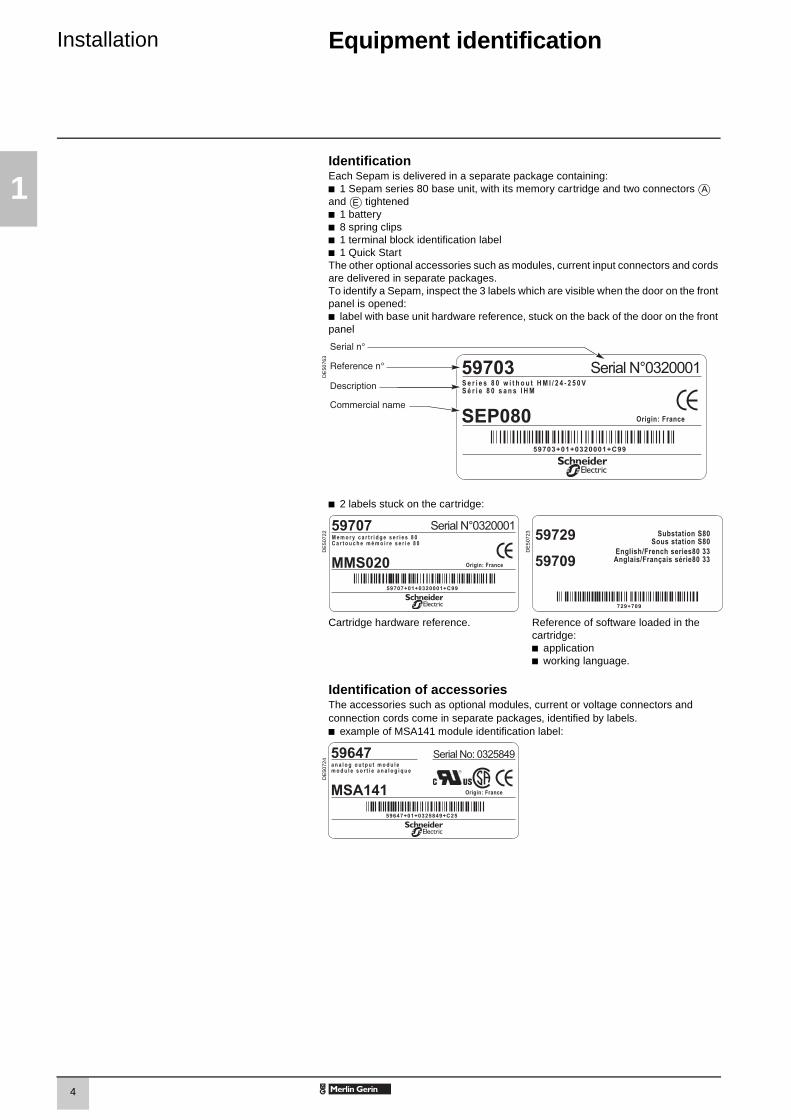
IdentificationEach Sepam is delivered in a separate package containing:b 1 Sepam series 80 base unit, with its memory cartridge and two connectors and tightenedb 1 batteryb 8 spring clipsb 1 terminal block identification labelb 1 Quick StartThe other optional accessories such as modules, current input connectors and cords are delivered in separate packages.To identify a Sepam, inspect the 3 labels which are visible when the door on the front panel is opened:b label with base unit hardware reference, stuck on the back of the door on the front panel
DE
5076
3
b 2 labels stuck on the cartridge:
DE
5072
2
DE
5072
3
Cartridge hardware reference. Reference of software loaded in the cartridge:b applicationb working language.
Identification of accessoriesThe accessories such as optional modules, current or voltage connectors and connection cords come in separate packages, identified by labels.b example of MSA141 module identification label:
DE
5072
4
A
E
SEPED303003EN_1-Installation.FM Page 4 Mardi, 24. juin 2003 2:03 14

5
1
Installation Equipment identification
List of Sepam series 80 referencesReference Designation
59608 DSM303, remote advanced UMI module
59630 CCA630 connector for 1A/5A CT current sensors
59634 CSH30 interposing ring CT for I0 input59635 CSH120 residual current sensor, diameter 120 mm59636 CSH200 residual current sensor, diameter 200 mm
59641 MET148-2 8-temperature sensor module59642 ACE949-2-wire RS 485 network interface
59643 ACE959 4-wire RS 485 network interface59644 ACE937 fiber optic interface
59647 MSA141 1 analog output module59648 ACE909-2 RS 485/RS 232 convertor59649 ACE919 AC RS 485/RS 485 interface (AC power supply)
59650 ACE919 DC RS 485/RS 485 interface (DC power supply)
59660 CCA770 remote module cord, L = 0.6 m
59661 CCA772 remote module cord, L = 2 m59662 CCA774 remote module cord, L = 4 m59663 CCA612 RS 485 network interface communication cord, L = 3 m
59664 CCA783 PC connection cord
59666 CCA613 remote LPCT test plug
59667 ACE917 LPCT injection adapter59668 CCA620 20-pin screw type connector
59669 CCA622 20-pin ring lug connector
59671 SFT2841 PC configuration software kit, with CCA783 cord
59672 ACE990 core balance CT interface for I0 input
59676 Kit 2640 with 2 sets of spare connectors for MES
59699 ATM820 shield
59702 CCA671 connector for LPCT current sensors59703 SEP080, base unit without UMI, 24-250 V DC power supply59704 SEP383, base unit with advanced UMI, 24-250 V DC power supply
59706 AMT880 mounting plate59707 MMS020 memory cartridge
59709 Working language English/French59710 Working language English/Spanish
59715 MES120 14 input + 6 output module / 24-250 V DC
59729 Substation application type S8059730 Substation application type S8159731 Substation application type S82
59733 Transformer application type T8159734 Transformer application type T82
59735 Transformer application type T8759736 Motor application type M8159737 Motor application type M87
59738 Motor application type M8859739 Generator application type G82
59741 Generator application type G8759742 Generator application type G88
SEPED303003EN_1-Installation.FM Page 5 Mardi, 24. juin 2003 2:03 14

6
1
Installation Precautions
Installation of Sepam Environment of the installed SepamWe recommend that you follow the instructions given in this document for quick, correct installation of your Sepam:b equipment identificationb assemblyb connection of current and voltage inputs, probesb connection of power supplyb checking prior to commissioning.
Handling, transport and storageSepam in its original packaging
Transport:Sepam may be shipped to any destination without talking any additional precautions by all usual means of transport.
Handling:Sepam may be handled without any particular care and can even withstand being dropped by a person handling it (person standing on floor).
Storage:Sepam may be stored in its original packaging, in an appropriate location for several years:b temperature between -25 °C and +70 °Cb humidity y 90 %.Periodic, yearly checking of the environment and the packaging condition is recommended.Once Sepam has been unpacked, it should be energized as soon as possible.
Sepam installed in a cubicle
Transport:Sepam may be transported by all usual means of transport in the customary conditions used for cubicles. Storage conditions should be taken into consideration for a long period of transport.
Handling:Should the Sepam fall out of a cubicle, check its condition by visual inspection and energizing.
Storage:Keep the cubicle protection packing for as long as possible. Sepam, like all electronic units, should not be stored in a damp environment for more than a month. Sepam should be energized as quickly as possible. If this is not possible, the cubicle reheating system should be activated.
Operation in a damp environmentThe temperature/relative humidity factors must compatible with the unit’s environmental withstand characteristics.If the use conditions are outside the normal zone, commissioning arrangements should be made, such as air conditioning of the premises.
MT
1114
9
Operation in a polluted atmosphereSepam is designed to be used in a clean industrial environment as defined by IEC 60654-4 class 1. A contaminated industrial atmosphere components (such as the presence of chlorine, hydrofluoric acid, sulfur, solvents...) may cause corrosion of the electronic components, in which case environmental control arrangements should be made (such as closed, pressurized premises with filtered air, ...) for commissioning.
SEPED303003EN_1-Installation.FM Page 6 Mardi, 24. juin 2003 2:03 14

7
1
Installation Base unitDimensions
Dimensions
DE
5006
0
DE
5057
7
Front view of Sepam.
Side view of Sepam with MES120, flush-mounted in front panel with spring clips.Support frame: 1.5 mm to 6 mm thick.
Clearance for Sepam assembly and wiring.
DE
5007
9
DE
5008
0
Cut-out. Top view of Sepam with MES120, flush-mounted in front panel with spring clips.Support frame: 1.5 mm to 6 mm thick.
Assembly with AMT880 mounting plate
DE
5008
1
DE
5008
2
Top view of Sepam with MES120, flush-mounted in front panel with spring clips.Mounting plate: 3 mm thick.
AMT880 mounting plate.
SEPED303003EN_1-Installation.FM Page 7 Mardi, 24. juin 2003 2:03 14

8
1
Installation Base unitMounting
Spring clip mounting directionThe direction in which the spring clips are mounted depends on the thickness of the mounting frame.The top clips are mounted in the opposite direction to the bottom clips.
Base unit flush-mountingSepam series 80 is mounted on the mounting frame by 8 spring clips.The mounting surface must be flat and stiff to guarantee tightness.
DE
5072
5
DE
5072
6D
E50
727
Fixing points.
Spring clips.
Setting.
Positioning.
Locking.
Unlocking.
PE
5011
0
Installing the terminal block identification labelA sticker showing the rear panel of Sepam and terminal assignments is supplied with each base unit to facilitate the installation and connection of Sepam and the MES120 input/output modules.You may stick it in the location of your choice, e.g. on the side of an MES120 module or on the right-hand side panel of Sepam.
Installing the batteryInstall the battery supplied in its housing, in accordance with the polarities indicated.
3CLIC !
4
5
5
CLAC !24x
14x
14x24x
CLIC !
6
1
2
3
4
5
6
SEPED303003EN_1-Installation.FM Page 8 Mardi, 24. juin 2003 2:03 14
9
1
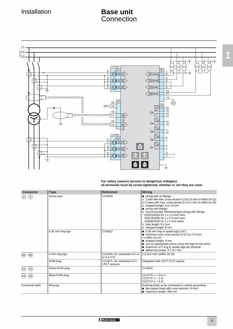
Installation Base unitConnection
DE
5054
6
For safety reasons (access to dangerous voltages),all terminals must be screw-tightened, whether or not they are used.
Connector Type Reference Wiring, Screw type CCA620 b wiring with no fittings :
v 1 wire with max. cross-section 0.2 to 2.5 mm² (u AWG 24-12)or 2 wires with max. cross-section 0.2 to 1 mm² (u AWG 24-16)v stripped length: 8 to 10 mmb wiring with fittings:v recommended Telemecanique wiring with fittings:- DZ5CE015D for 1 x 1.5 mm² wire- DZ5CE025D for 1 x 2.5 mm² wire- AZ5DE010D for 2 x 1 mm² wiresv tube length: 8.2 mmv stripped length: 8 mm
6.35 mm ring lugs CCA622 b 6.35 mm ring or spade lugs (1/4")b maximum wire cross-section of 0.2 to 2.5 mm² (u AWG 24-12)b stripped length: 6 mmb use an appropriate tool to crimp the lugs on the wiresb maximum of 2 ring or spade lugs per terminalb tightening torque: 0.7 to 1 Nm
, 4 mm ring lugs CCA630, for connection of 1 A or 5 A CTs
1.5 to 6 mm² (AWG 16-10)
RJ45 plug CCA671, for connection of 3 LPCT sensors
Integrated with LPCT CLP1 sensor
, Green RJ45 plug CCA612
, Black RJ45 plug CCA770: L = 0.6 mCCA772: L = 2 mCCA774: L = 4 m
Functional earth Ring lug Earthing braid, to be connected to cubicle grounding:b flat copper braid with cross-section u 9 mm²b maximum length: 300 mm
A E
B1 B2
C1 C2
D1 D2
SEPED303003EN_1-Installation.FM Page 9 Mardi, 24. juin 2003 2:03 14

10
1
Installation Base unitPhase current inputs connection
Variant 1: phase current measurement by 3 x 1 A or 5 A CTs (standard connection)
DE
5004
3
Connection of 3 x 1 A or 5 A sensors to the CCA630 connector.
The measurement of the 3 phase currents allows the calculation of residual current.
Variant 2: phase current measurement by 2 x 1 A or 5 A CTs
DE
5004
4
Connection of 2 x 1 A or 5 A sensors to the CCA630 connector.
Measurement of phase 1 and 3 currents is sufficient for all protection functions based on phase current.
This arrangement does not allow the calculation of residual current.
Variant 3: phase current measurement by 3 LPCT type sensors
DE
5004
5
Connection of 3 Low Power Current Transducer (LPCT) type sensors to the CCA671 connector. It is necessary to connect 3 sensors; if only one or two sensors are connected, Sepam goes into fail-safe position.
Measurement of the 3 phase currents allows the calculation of residual current.
The In parameter, primary rated current measured by an LPCT, is to be chosen from the following values, in Amps: 25, 50, 100, 125, 133, 200, 250, 320, 400, 500, 630, 666, 1000, 1600, 2000, 3150.Parameter to be set using the SFT2841 software tool, to be completed by hardware setting of the microswitches on the CCA671 connector.
Possible combinations of types of sensors per application
b Sepam units without ANSI 87T or 87M differential protection functions measure 2 or 3 phase currents by means of sensors connected to connector b Sepam M87 and G87 units with ANSI 87M machine differential protection measure2 x 3 phase currents:v 3 CTs or 3 LPCTs at the circuit breaker end connected to connector v 3 CTs or 3 LPCTs connected to connector b Sepam T87, M88 and G88 units with ANSI 87T transformer differential protection measure 2 x 3 phase currents by means of 2 sets of 3 current transformers:v 3 CTs at the circuit breaker end connected to connector v 3 CTs connected to connector .
Sensors connected to Sepam without ANSI 87M or 87T
Sepam with ANSI 87M Sepam with ANSI 87T
Connector 2 CTs or 3 CTs connected to CCA630 or 3 LPCTs to CCA671
3 CTs connected to CCA630or 3 LPCTs to CCA671
3 CT connected to CCA630
Connector 3 CTs connected to CCA630or 3 LPCTs to CCA671
3 CTs connected to CCA630
B1
B1B2
B1B2
B1
B2
SEPED303003EN_1-Installation.FM Page 10 Mardi, 24. juin 2003 2:03 14

11
1
Installation Base unitResidual current inputs connection
Variant 1: residual current calculation by sum of 3 phase currents
Residual current is calculated by the vector sum of the 3 phase currents I1, I2 and I3, measured by 3 x 1 A or 5 A CTs or by 3 LPCT type sensors.See current input connection diagrams.
Variant 2: residual current measurement by CSH120 or CSH200 core balance CT (standard connection)
DE
5057
8
Arrangement recommended for the protection of isolated or compensated neutral systems, in which very low fault currents need to be detected.
Setting range from 0.01 In0 to 15 In0 (minimum 0.1 A), with In0 = 2 A or 20 A according to parameter setting.
Variant 3: residual current measurement by 1 A or 5 A CTs and CSH30 interposing ring CT
DE
5058
4
The CSH30 interposing ring CT is used to connect 1 A or 5 A CTs to Sepam to measure residual current:b CSH30 interposing ring CT connected to 1 A CT: make 2 turns through CSH primaryb CSH30 interposing ring CT connected to 5 A CT: make 4 turns through CSH primary.
Setting range from 0.01 In to 15 In (minimum 0.1 A), with In = CT primary current.
DE
5058
5
Variant 4: residual current measurement by core balance CT with ratio of 1/n (n between 50 and 1500)
DE
5058
1
The ACE990 is used as an interface between a MV core balance CT with a ratio of 1/n (50 y n y 1500) and the Sepam residual current input.This arrangement allows the continued use of existing core balance CTs on the installation.
Setting range from 0.01 In0 to 15 In0 (minimum 0.1 A), with In0 = k.n, where n = number of core balance CT turnsand k = factor to be determined according to ACE990 wiring and setting range
used by Sepam, with a choice of 20 discrete values from 0.00578to 0.26316.
SEPED303003EN_1-Installation.FM Page 11 Mardi, 24. juin 2003 2:03 14

12
1
Installation Base unitPhase voltage and residual voltage inputs connection
Phase voltage input connection variantsVariant 1: measurement of 3 phase-to-neutral voltages (3 V, standard connection)
Variant 2: measurement of 2 phase-to-phase voltages (2 U)
DE
5004
6
DE
5004
7
Measurement of the 3 phase-to-neutral voltages allows the calculation of residual voltage, V0Σ.
This variant does not allow the calculation of residual voltage.
Variant 3: measurement of 1 phase-to-phase voltage (1 U)
Variant 4: measurement of 1 phase-to-neutral voltage (1 V)
DE
5004
8
DE
5004
9
This variant does not allow the calculation of residual voltage.
This variant does not allow the calculation of residual voltage.
Residual voltage input connection variantsVariant 5: measurement of residual voltage V0 Variant 6: measurement of residual voltage Vnt in generator neutral point
DE
5005
0
DE
5005
1
SEPED303003EN_1-Installation.FM Page 12 Mardi, 24. juin 2003 2:03 14

13
1
Installation Base unitPhase voltage and residual voltage inputs connection
The availability of certain protection and metering functions depend on the phase and residual voltages measured by Sepam.
The table below gives the voltage input connection variants for which each protection and metering function dependent on measured voltages is available.Example:The directional overcurrent protection function (ANSI 67N/67NC) uses residual voltage V0 as a polarization value.It is therefore operational in the following cases:b measurement of the 3 phase-to-neutral voltages and calculation of V0Σ (3 V + V0Σ, variant 1)b measurement of residual voltage V0 (variant 5).The protection and metering functions which do not appear in the table below are available regardless of the voltages measured.
Phase voltages measured(connection variant)
3 V + V0Σ(var. 1)
2 U(var. 2)
1 U(var. 3)
1 V(var. 4)
Residual voltage measured(connection variant)
– V0(v. 5)
Vnt(v. 6)
– V0(v. 5)
Vnt(v. 6)
– V0(v. 5)
Vnt(v. 6)
– V0(v. 5)
Vnt(v. 6)
Protection functions dependent on voltages measuredDirectional phase overcurrent 67 b b b b b bDirectional earth fault 67N/67NC b b b b b bDirectional active overpower 32P b b b b b bDirectional reactive active overpower 32Q b b b b b bDirectional active underpower 37P b b b b b bField loss (underimpedance) 40 b b b b b bPole slip 78PS b b b b b bVoltage-restrained overcurrent 50V/51V b b b b b bUnderimpedance 21B b b b b b bInadvertent energization 50/27 b b b b b bThird harmonic undervoltage /100 % stator earth fault
27TN/64G264G
b b
Overfluxing (V/Hz) 24 b b b b b b b b b b b bPositive sequence undervoltage 27D b b b b b bRemanent undervoltage 27R b b b b b b b b b b b bUndervoltage (L-L or L-N) 27 b b b b b b b b b b b bOvervoltage (L-L or L-N) 59 b b b b b b b b b b b bNeutral voltage displacement 59N b b b b b b b b bNegative sequence overvoltage 47 b b b b b bOverfrequency 81H b b b b b b b b b b b bUnderfrequency 81L b b b b b b b b b b b bMeasurements dependent on voltages measured
Phase-to-phase voltage U21, U32, U13 b b b b b b U21 U21 U21Phase-to-neutral voltage V1, V2, V3 b b b b V1 V1 V1
Residual voltage V0 b b b b b bNeutral point voltage Vnt b b b bThird harmonic neutral point voltage b b b bThird harmonic residual voltage b b b b b bPositive sequence voltage Vd / negative sequence voltage Vi
b b b b b b
Frequency b b b b b b b b b b b bActive / reactive / apparent power: P, Q, S b b b b b b b b bPeak demand power PM, QM b b b b b b b b bActive / reactive / apparent power per phase :P1/P2/P3, Q1/Q2/Q3, S1/S2/S3
b (1) b (1) b (1) b (1) P1/Q1/S1
P1/Q1/S1
P1/Q1/S1
Power factor b b b b b b b b bCalculated active and reactive energy (±Wh, ±VARh) b b b b b b b b bTotal harmonic distortion, voltage Uthd b b b b b b b b b b b b(1) Only if 3 CTs are connected.
SEPED303003EN_1-Installation.FM Page 13 Mardi, 24. juin 2003 2:03 14

14
1
Installation MES120 14 input / 6 output module
FunctionThe 5 output relays included on the Sepam series 80 base unit may be extended by adding 1, 2 or 3 MES120 modules with 14 DC logic inputs (24 V DC to 250 V DC) and 6 outputs relays, 1 control relay output and 5 indication relay outputs. P
E50
020
CharacteristicsMES120 module
Weight 0.38 kgOperating temperature -25°C to +70°CEnvironmental characteristics Same characteristics as Sepam base units
Logic inputsVoltage 24 - 250 V DC -20 / +10 % (19.2 to 275 V DC)
Typical consumption 3 mA Typical switching threshold 14 V DC
Control relay outputVoltage DC 24/48 V DC 127 V DC 220 V DC
MES120 14 input / 6 output module. AC(47.5 to 63 Hz)
100 to 240 V AC
Continuous current 8 A 8 A 8 A 8 A
Breaking capacity Resistive load 8 / 4 A 0.7 A 0.3 A 8 ALoadL/R < 20 ms
6 / 2 A 0.5 A 0.2 A
Load L/R < 40 ms
4 / 1 A 0.2 A 0.1 A
Loadp.f. > 0.3
5 A
Making capacity < 15 A for 200 ms
Indication relay outputVoltage DC 24/48 V DC 127 V DC 220 V DC
AC(47.5 to 63 Hz)
100 to 240 V AC
Continuous current 2 A 2 A 2 A 2 ABreaking capacity Load
L/R < 20 ms2 / 1 A 0.5 A 0.15 A
Loadp.f. > 0.3
1 A
Description3 removable, lockable screw-type connectors.1 20-pin connector for 9 logic inputs:
b Ix01 to Ix04: 4 independent logic inputsb Ix05 to Ix09: 5 common point logic inputs.
2 7-pin connector for 5 common point logic inputs Ix10 à Ix14.3 17-pin connector for 6 relay outputs:
b Ox01: 1 control relay outputb Ox02 to Ox06 : 5 indication relay outputs.
Addressing of MES120 module inputs / outputs:b x = 1 for the module connected to H1b x = 2 for the module connected to H2b x = 3 for the module connected to H3.
DE
5010
1
SEPED303003EN_1-Installation.FM Page 14 Mardi, 24. juin 2003 2:03 14

15
1
Installation MES120 14 input / 6 output module
AssemblyInstallation of an MES120 module on the base unitb insert the 2 pins on the MES module into the slots 1 on the base unitb flatten the module up against the base unit to plug it into the connector H2b partially tighten the two mounting screws 2 before locking them.
MES120 modules must be mounted in the following order:b if only one module is required, connect it to connector H1b if 2 modules are required, connect them to connectors H1 and H2b if 3 modules are required (maximum configuration), the 3 connectors H1, H2 and H3 are used.
PE
5002
6
Installation of the second MES120 module, connected to base unit connector H2.
ConnectionFor safety reasons (access to dangerous voltages), all terminals must be screwed tight, whether or not they are used.The inputs are potential-free and the DC power supply source is external.
Wiring of connectorsb wiring without fitting:v 1 wire with maximum cross-section 0.2 to 2.5 mm² (u AWG 24-12) or 2 wires with maximum cross-section 0.2 to 1 mm² (u AWG 24-16)v stripped length: 8 to 10 mmb wiring with fittings:v recommended wiring with Telemecanique fitting:- DZ5CE015D for one 1.5 mm² wire- DZ5CE025D for one 2.5 mm² wire- AZ5DE010D for two 1 mm² wiresv tube length: 8.2 mmv stripped length: 8 mm.
DE
5010
5
SEPED303003EN_1-Installation.FM Page 15 Mardi, 24. juin 2003 2:03 14
16
1
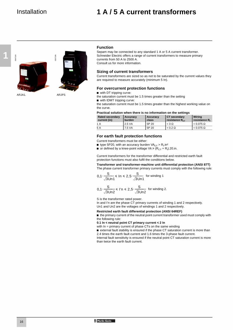
Installation 1 A / 5 A current transformers
FunctionSepam may be connected to any standard 1 A or 5 A current transformer.Schneider Electric offers a range of current transformers to measure primary currents from 50 A to 2500 A. Consult us for more information.
0587
31N
ARJA1.
0587
33N
ARJP3.
Sizing of current transformersCurrent transformers are sized so as not to be saturated by the current values they are required to measure accurately (minimum 5 In).
For overcurrent protection functionsb with DT tripping curve: the saturation current must be 1.5 times greater than the settingb with IDMT tripping curve:the saturation current must be 1.5 times greater than the highest working value on the curve.
Practical solution when there is no information on the settingsRated secondary current (in)
Accuracy burden
Accuracy class
CT secondary resistance RCT
Wiring resistance Rf
1 A 2.5 VA 5P 20 < 3 Ω < 0.075 Ω5 A 7.5 VA 5P 20 < 0.2 Ω < 0.075 Ω
For earth fault protection functionsCurrent transformers must be either:b type 5P20, with an accuracy burden VACT > Rf.in²b or defined by a knee-point voltage Vk u (RCT + Rf).20.in.
Current transformers for the transformer differential and restricted earth fault protection functions must also fulfil the conditions below.
Transformer and transformer-machine unit differential protection (ANSI 87T)The phase current transformer primary currents must comply with the following rule:
for winding 1
for winding 2.
S is the transformer rated power.In and I’n are the phase CT primary currents of winding 1 and 2 respectively.Un1 and Un2 are the voltages of windings 1 and 2 respectively.
Restricted earth fault differential protection (ANSI 64REF)b the primary current of the neutral point current transformer used must comply with the following rule:0.1 In y neutral point CT primary current y 2 In with In = primary current of phase CTs on the same windingb external fault stability is ensured if the phase CT saturation current is more than 2.4 times the earth fault current and 1.6 times the 3-phase fault current.Internal fault sensitivity is ensured if the neutral point CT saturation current is more than twice the earth fault current.
0,1. y In y 2,5.S
3Un1--------------- - S
3Un1----------------- -
0,1. y I'n y 2,5.S
3Un2----------------- S
3Un2------------------ -
SEPED303003EN_1-Installation.FM Page 16 Mardi, 24. juin 2003 2:03 14

17
1
Installation 1 A / 5 A current transformers
DE
5005
6
CCA630 connectorFunctionThe CCA630 connector is used to connect Sepam to 1 A or 5 A current transformer secondary windings. It contains 3 interposing ring CTs with through primaries, which ensure impedance matching and isolation between the 1 A or 5 A circuits and Sepam.The connector may be disconnected with the power on since disconnection does not open the CT secondary circuits.
Connectionb open the 2 side shields for access to the connection terminals.The shields may be removed, if necessary, to make wiring easier. If removed, they must be replaced after wiring.b remove the bridging strap, if necessary. The strap links terminals 1, 2 and 3.b connect the wires using 4 mm ring lugs. The connector accepts wires with cross-sections of 1.5 to 6 mm² (AWG 16 to AWG 10).b the terminal 1, 2 and 3 bridging strap is supplied with the CCA630b close the side shieldsb plug the connector into the 9-pin inlet on the rear panelb tighten the 2 CCA630 connector fastening screws on the rear panel of Sepam.
Mt1
0318
SEPED303003EN_1-Installation.FM Page 17 Mardi, 24. juin 2003 2:03 14

18
1
Installation LPCT type current sensorsCLP1 sensors
FunctionCLP1 sensors are voltage-output sensors of the Low Power Current Transducer (LPCT) type, compliant with the IEC 60044-8 standard.CLP1 sensors are designed to measure rated currents between 25 A and 1250 A, with a ratio of 100 A / 22.5 mV, and may be used on networks with a maximum voltage of 17.5 kV.
PE
5003
1
CharacteristicsAccording to IEC 60044-8 standard
Rated primary current 100 ARated secondary voltage 22.5 mVRated extended primary current 1250 A
Measurement accuracy class 0.5 0.5% between 100 and 1250 A0.75% at 20 A1.5% at 5 A
Protection accuracy class 5PRated accuracy limit primary current 40 kAAccuracy burden u 2 kΩRated thermal short-circuit current 31.5 kA x 4 s - 40 kA x 3 sRated voltage (Um) 17.5 kV
CLP1 sensor. Rated power frequency withstand voltage 38 kV - 42 kV
Rated lightning impulse withstand voltage 95 kVWeight 8 kg
CCA670/CCA671 connectorFunctionThe secondary winding of the CLP1 sensor is pre-equipped with a 5-meter shielded cable fitted with a yellow RJ 45 plug. The 3 LPCT current transformers are connected to the CCA670 or CCA671 connector on the rear panel of Sepam.The connection of just one or two LPCT sensors is not allowed and causes Sepam to go into fail-safe position.The two CCA670 and CCA671 interface connectors serve the same purpose, the difference being the position of the CLP1 sensor plugs:b CCA670: lateral plugs, for Sepam series 20 and Sepam series 40b CCA671: radial plugs, for Sepam series 80.
Description1 3 RJ 45 plugs to connect the LPCT sensors.2 3 blocks of microswitches to set the CCA670/CCA671 to the rated phase current
value.3 Microswitch setting / selected rated current equivalency table (2 In values per
setting).4 9-pin sub-D connector to connect test equipment (ACE917 for direct connector
or via CCA613).
Rating of CCA670/CCA671 connectors The CCA670/CCA671 connector must be rated according to the rated primary current In measured by the LPCT sensors. The following settings are available, in Amperes: 25, 50, 100, 125, 133, 200, 250, 320, 400, 500, 630, 666, 1000, 1600, 2000, 3150.The selected In value should be:b entered as a Sepam general setting b configured by microswitch on the CCA670/CCA671 connector.Instructions:b use a screwdriver to remove the shield located in the "LPCT settings" zone; the shield protects 3 blocks of 8 microswitches marked L1, L2, L3b on the L1 block, set the microswitch for the selected rated current to "1" (2 In values per microswitch)v the table of equivalencies between the microswitch settings and the selected rated current In is printed on the connectorv leave the 7 other microswitches set to "0"b set the other 2 blocks of microswitches L2 and L3 in the same position as the L1 block and close the shield.
DE
5005
7
SEPED303003EN_1-Installation.FM Page 18 Mardi, 24. juin 2003 2:03 14

19
1
Installation LPCT type current sensorsTest accessories
DE
5058
2
Accessory connection principle 1 CLP1 sensor, equipped with a shielded cable (L = 5 m) fitted with a yellow RJ 45
plug which is plugged directly into the CCA670/CCA671 connector.
2 Sepam protection unit.
3 CCA670/CCA671 connector, CLP1 voltage interface, with microswitch setting of rated current:b CCA670: lateral plugs for Sepam series 20 and Sepam series 40b CCA671: radial plugs for Sepam series 80.
4 CCA613 remote test plug, flush-mounted on the front of the cubicle and equipped with a 3-meter cord to be plugged into the test plug of the CCA670/CCA671 interface connector (9-pin sub-D).
5 ACE917 injection adapter, to test the LPCT protection chain with a standard injection box.
6 Standard injection box.
ACE917 injection adapterFunctionThe ACE917 adapter is used to test the protection chain with a standard injection box, when Sepam is connected to LPCT sensors.The ACE917 adapter is inserted between:b the standard injection boxb the LPCT test plug:v integrated in the Sepam CCA670/CCA671 interface connectorv or transferred by means of the CCA613 accessory.
The following are supplied with the ACE917 injection adapter:b power supply cordb 3-meter cord to connect the ACE917 to the LPCT test plug on CCA670/CCA671 or CCA613.
Characteristics
DE
5007
3
Power supply 115 / 230 V AC Protection by time-delayed fuse 5 mm x 20 mm 0.25 A rating
CCA613 remote test plugFunctionThe CCA613 test plug, flush-mounted on the front of the cubicle, is equipped with a 3-meter cord to transfer data from the test plug integrated in the CCA670/CCA671 interface connector on the rear of Sepam.
Description and dimensions1 Mounting lug2 Cord
DE
5005
9
Front view with cover lifted. Right side view. Cutout.
4
23
5
1
6
SEPED303003EN_1-Installation.FM Page 19 Mardi, 24. juin 2003 2:03 14

20
1
Installation CSH120 and CSH200Core balance CTs
FunctionThe specifically designed CSH120 and CSH200 core balance CTs are used for direct residual current measurement. The only difference between them is the diameter. Due to their low voltage insulation, they may only be used on cables.P
E50
032
Characteristics
CSH120 CSH200Inner diameter 120 mm 200 mmWeight 0.6 kg 1.4 kgAccuracy ±5% to 20°C
±6% max. from -25°C to 70°CTransformation ratio 1/470Maximum permissible current 20 kA - 1 sOperating temperature - 25°C to +70°C
CSH120 and CSH200 core balance CTs. Storage temperature - 40°C to +85°C
Dimensions
DE
1022
8
Dimensions A B D E F H J K LCSH120 120 164 44 190 76 40 166 62 35CSH200 200 256 46 274 120 60 257 104 37
AssemblyGroup the MV cable (or cables) in the middle of the core balance CT.Use non-conductive binding to hold the cables.Remember to insert the 3 medium voltage cable shielding earthing cables through the core balance CT.
E40
465
E40
466
DE
5006
4
Assembly on MV cables. Assembly on mounting plate.
ConnectionConnection to Sepam series 20 and Sepam series 40
To residual current I0 input, on connector , terminals 19 and 18 (shielding).
Connection to Sepam series 80b to residual current I0 input, on connector , terminals 15 and 14 (shielding)
b to residual current I’0 input, on connector , terminals 18 and 17 (shielding).
Recommended cableb sheathed cable, shielded by tinned copper braidb minimum cable cross-section 0.93 mm² (AWG 18)b resistance per unit length < 100 mΩ/mb minimum dielectric strength: 1000 V.It is essential for the CSH30 to be installed near Sepam (Sepam - CSH30 link less than 2 m.Flatten the connection cable against the metal frames of the cubicle.The connection cable shielding is grounded in Sepam. Do not ground the cable by any other means.The maximum resistance of the Sepam connection wiring must not be more than 4 Ω.
DE
5006
5
A
E
E
SEPED303003EN_1-Installation.FM Page 20 Mardi, 24. juin 2003 2:03 14

21
1
Installation CSH30Interposing ring CT
FunctionThe CSH30 interposing ring CT is used as an interface when the residual current is measured using 1 A or 5 A current transformers.
E40
468
E44
717
Characteristics
Weight 0.12 kgAssembly On symmetrical DIN rail
In vertical or horizontal positionVertical assembly of CSH30 interposing ring CT.
Horizontal assembly of CSH30 interposing ring CT.
Dimensions
DE
5006
6
ConnectionThe CSH30 is adapted for the type of current transformer, 1 A or 5 A, by the number of turns of the secondary wiring through the CSH30 interposing ring CT :5 A rating - 4 turns1 A rating - 2 turns.
Connection to 5 A secondary circuit Connection to 1 A secondary circuit
PE
5003
3
PE
5003
4
b plug into the connectorb insert the transformer secondary wire through the CSH30 core balance CT 4 times.
b plug into the connectorb insert the transformer secondary wire through the CSH30 core balance CT twice.
DE
5028
3
Connection to Sepam series 20 and Sepam series 40
To residual current I0 input, on connector , terminals 19 and 18 (shielding).
Connection to Sepam series 80b to residual current I0 input, on connector , terminals 15 and 14 (shielding)
b to residual current I’0 input, on connector , terminals 18 and 17 (shielding).
Recommended cableb sheathed cable, shielded by tinned copper braidb minimum cable cross-section 0.93 mm² (AWG 18) (max. 2.5 mm²)b resistance per unit length < 100 mΩ/mb minimum dielectric strength: 1000 V.It is essential for the CSH30 to be installed near Sepam (Sepam - CSH30 link less than 2 meters long).Flatten the connection cable against the metal frames of the cubicle.The connection cable shielding is grounded in Sepam. Do not ground the cable by any other means.
A
E
E
SEPED303003EN_1-Installation.FM Page 21 Mardi, 24. juin 2003 2:03 14

22
1
Installation ACE990Core balance CT interface
FunctionThe ACE990 interface is used to adapt measurements between a MV core balance CT with a ratio of 1/n (50 y n y 1500), and the Sepam residual current input.
PE
5003
7
Characteristics
Weight 0.64 kgAssembly Mounted on symmetrical DIN railAmplitude accuracy ±1%
Phase accuracy < 2°Maximum permissible current 20 kA - 1 s
(on the primary winding of a MV core balance CT with a ratio of 1/50 that does not saturate)
ACE990 core balance CT interface. Operating temperature -5°C to +55°C
Storage temperature -25°C to +70°C
Description and dimensions
DE
5006
9
ACE990 input terminal block, for connection of the core balance CT.
ACE990 output terminal block, for connection of the Sepam residual current input.
E
S
SEPED303003EN_1-Installation.FM Page 22 Mardi, 24. juin 2003 2:03 14

23
1
Installation ACE990Core balance CT interface
ConnectionConnection of core balance CTOnly one core balance CT may be connected to the ACE990 interface.The secondary circuit of the MV core balance CT is connected to 2 of the 5 ACE990 interface input terminals. To define the 2 inputs, it is necessary to know the following:b core balance CT ratio (1/n)b core balance CT powerb close approximation of rated current In0(In0 is a Sepam general setting and defines the earth fault protection setting range between 0.1 In0 and 15 In0).
The table below may be used to determineb the 2 ACE990 input terminals to be connected to the MV core balance CT secondaryb the type of residual current sensor to set b the exact value of the rated residual current In0 setting, given by the following formula: In0 = k x number of core balance CT turnswith k the factor defined in the table below.
The core balance CT must be connected to the interface in the right direction for correct operation: the MV core balance CT secondary output terminal S1 must be connected to the ACE990 input terminal with the lowest index (Ex).
DE
5007
1
K value ACE990 input terminals to be connected
Residual current sensor setting
Min. MV core balance CT power
Example: Given a core balance CT with a ratio of 1/400 2 VA, used within a measurement range of 0.5 A to 60 A.How should it be connected to Sepam via the ACE990?1 Choose a close approximation of the rated current In0,
i.e. 5 A.2 Calculate the ratio:
approx. In0/number of turns = 5/400 = 0.0125.3 Find the closest value of k in the table opposite:
k = 0.01136.4 Check the mininum power required for the core balance CT:
2 VA core balance CT > 0.1 VA V OK.5 Connect the core balance secondary to ACE990 input
terminals E2 and E4.6 Set Sepam up with:
In0 = 0.0136 x 400 = 4.5 A.
This value of In0 may be used to monitor current between 0.45 A and 67.5 A.
Wiring of MV core balance secondary circuit:b MV core balance CT S1 output to ACE990 E2 input terminal b MV core balance CT S2 output to ACE990 E4 input terminal.
0.00578 E1 - E5 ACE990 - range 1 0.1 VA0.00676 E2 - E5 ACE990 - range 1 0.1 VA
0.00885 E1 - E4 ACE990 - range 1 0.1 VA0.00909 E3 - E5 ACE990 - range 1 0.1 VA0.01136 E2 - E4 ACE990 - range 1 0.1 VA0.01587 E1 - E3 ACE990 - range 1 0.1 VA0.01667 E4 - E5 ACE990 - range 1 0.1 VA0.02000 E3 - E4 ACE990 - range 1 0.1 VA
0.02632 E2 - E3 ACE990 - range 1 0.1 VA0.04000 E1 - E2 ACE990 - range 1 0.2 VA
0.05780 E1 - E5 ACE990 - range 2 2.5 VA0.06757 E2 - E5 ACE990 - range 2 2.5 VA0.08850 E1 - E4 ACE990 - range 2 3.0 VA
0.09091 E3 - E5 ACE990 - range 2 3.0 VA0.11364 E2 - E4 ACE990 - range 2 3.0 VA0.15873 E1 - E3 ACE990 - range 2 4.5 VA
0.16667 E4 - E5 ACE990 - range 2 4.5 VA0.20000 E3 - E4 ACE990 - range 2 5.5 VA
0.26316 E2 - E3 ACE990 - range 2 7.5 VA
Connection to Sepam series 20 and Sepam series 40
To residual current I0 input, on connector , terminals 19 and 18 (shielding).
Connection to Sepam series 80b to residual current I0 input, on connector , terminals 15 and 14 (shielding)
b to residual current I’0 input, on connector , terminals 18 and 17 (shielding).
Recommended cablesb cable between core balance CT and ACE990: less than 50 m longb sheathed cable, shielded by tinned copper braid between the ACE990 and Sepam, maximum length 2 mb cable cross-section between 0.93 mm² (AWG 18) and 2.5 mm² (AWG 13)b resistance per unit length less than 100 mΩ/mb minimum dielectric strength: 100 V.Connect the ACE990 connection cable shielding in the shortest manner possible (2 cm maximum) to the shielding terminal on the Sepam connector.Flatten the connection cable against the metal frames of the cubicle.The connection cable shielding is grounded in Sepam. Do not ground the cable by any other means.
A
E
E
SEPED303003EN_1-Installation.FM Page 23 Mardi, 24. juin 2003 2:03 14

24
1
Installation Remote modules
Selection guide3 remote modules are proposed as options to enhance the Sepam base unit functions:b the number and type of remote modules compatible with the base unit depend on the Sepam applicationb the DSM303 remote advanced UMI module is only compatible with base units that do not have integrated advanced UMIs.
Sepam series 20 Sepam series 40 Sepam series 80S2x, B2x T2x, M2x S4x T4x, M4x, G4x S8x T8x, M8x, G8x
MET148-2 Temperature sensor module See page 25 0 1 0 2 0 2MSA141 Analog output module See page 26 1 1 1 1 1 1DSM303 Remote advanced UMI module See page 27 1 1 1 1 1 1
Number of sets of interlinked modules / maximum number of remote modules
1 set of 3 interlinked modules
1 set of 3 interlinked modules 4 modules split between 2 sets of interlinked modules
Connection Connection cordsDifferent combinations of modules may be connected using cords fitted with 2 black RJ45 connectors, which come in 3 lengths:b CCA770: length = 0.6 mb CCA772: length = 2 mb CCA774: length = 4 m.The modules are linked by cords which provide the power supply and act as functional links with the Sepam unit (connector to connector , to , …).
Rules on inter-module linkingb linking of 3 modules maximumb DSM303 module may only be connected at the end of the link.
Maximum advisable configurations
Sepam series 20 and Sepam series 40: just 1 set of interlinked modules
DE
5008
8
Base Cord Module 1 Cord Module 2 Cord Module 3
DE
5008
9
series 20 CCA772 MSA141 CCA770 MET148-2 CCA774 DSM303series 40 CCA772 MSA141 CCA770 MET148-2 CCA774 DSM303
series 40 CCA772 MSA141 CCA770 MET148-2 CCA772 MET148-2series 40 CCA772 MET148-2 CCA770 MET148-2 CCA774 DSM303
Sepam series 80: 2 sets of interlinked modulesSepam series 80 has 2 connection ports for remote modules, and .Modules may be connected to either port.Base Cord Module 1 Cord Module 2 Cord Module 3
DE
5009
0
Example of inter-module linking on Sepam series 20.
Set 1 CCA772 MSA141 CCA770 MET148-2 CCA770 MET148-2
Set 2 CCA774 DSM303 - - - -
D DaDd Da
D1 D2
D1
D2
SEPED303003EN_1-Installation.FM Page 24 Mardi, 24. juin 2003 2:03 14

25
1
Installation MET148-2Temperature sensor modules
FunctionThe MET148-2 module may be used to connect 8 temperature sensors (RTDs) of the same type:b Pt100, Ni100 or Ni120 type RTDs, according to parameter settingb 3-wire temperature sensorsb a single module for each Sepam series 20 base unit, to be connected by one of the CCA770, CCA772 or CCA774 cords (0.6 or 2 or 4 meters))b 2 modules for each Sepam series 40 or series 80 base unit, to be connected by CCA770, CCA772 or CCA774 cords (0.6 or 2 or 4 meters).
The temperature measurement (e.g. in a transformer or motor winding) is utilized by the following protection functions:b thermal overload (to take ambient temperature into account)b temperature monitoring.
PE
5002
1
MET148-2 temperature sensor module.
CharacteristicsMET148-2 module
Weight 0.2 kgAssembly On symmetrical DIN railOperating temperature -25°C to +70°CEnvironmental characteristics Same characteristics as Sepam base units
RTDs Pt100 Ni100 / Ni120Isolation from earth None NoneCurrent injected in RTD 4 mA 4 mA
DE
5008
5
Description and dimensionsTerminal block for RTDs 1 to 4.
Terminal block for RTDs 5 to 8.
RJ45 connector to connect the module to the base unit with a CCA77x cord.
RJ45 connector to link up the next remote module with a CCA77x cord (according to application).Grounding/earthing terminal.
1 Jumper for impedance matching with load resistor (Rc), to be set to:b , if the module is not the last interlinked module (default position)b Rc, if the module is the last interlinked module.
2 Jumper used to select module number, to be set to:b MET1: 1st MET148-2 module, to measure temperatures T1 to T8 (default position)b MET2: 2nd MET148-2 module, to measure temperatures T9 to T16(for Sepam series 40 and series 80 only).
(1) 70 mm with CCA77x cord connected.
ConnectionConnection of the earthing terminalBy tinned copper braid or cable fitted with a 4 mm ring lug.
Connection of RTDs to screw-type connectorsb 1 wire with cross-section 0.2 to 2.5 mm² (u AWG 24-12)b or 2 wires with cross-section 0.2 to 1 mm² (u AWG 24-16).Recommended cross-sections according to distance:b up to 100 m u 1 mm², AWG 16b up to 300 m u 1.5 mm², AWG 14b up to 1 km u 2.5 mm², AWG 12
Wiring precautionsb it is preferable to use shielded cablesThe use of unshielded cables may cause measurement errors, which vary in degree on the level of surrounding electromagnetic disturbanceb only connect the shielding at the MET148-2 end, in the shortest manner possible, to the corresponding terminals of connectors and b do not connect the shielding at the RTD end.
Accuracy derating according to wiringThe error ∆t is proportional to the length of the cable and inversely proportional to the cable cross-section:
b ±2.1°C/km for 0.93 mm² cross-sectionb ±1°C/km for 1.92 mm² cross-section.
MT
1015
3
A
B
Da
Dd
t
Rc
A B
∆t °C( ) 2 L km( )S mm2( )----------------------×=
SEPED303003EN_1-Installation.FM Page 25 Mardi, 24. juin 2003 2:03 14

26
1
Installation MSA141Analog output module
FunctionThe MSA141 module converts one of the Sepam measurements into an analog signal:b selection of the measurement to be converted by parameter settingb 0-10 mA, 4-20 mA, 0-20 mA analog signal according to parameter settingb scaling of the analog signal by setting minimum and maximum values of the converted measurement.Example: the setting used to have phase current 1 as a 0-10 mA analog output with a dynamic range of 0 to 300 A is:v minimum value = 0v maximum value = 3000b a single module for each Sepam base unit, to be connected by one of the CCA770, CCA772 or CCA774 cords (0.6 or 2 or 4 meters).
The analog output may also be remotely managed via the Modbus communication network.
Mt1
1009
MSA141 analog output module.
CharacteristicsMSA141 module
Weight 0.2 kgAssembly On symmetrical DIN railOperating temperature -25 °C to +70 °CEnvironmental characteristics Same characteristics as Sepam base unitsAnalog output
Current 4-20 mA, 0-20 mA, 0-10 mAScaling (no data input checking) Minimum value
Maximum valueLoad impedance < 600 Ω (wiring included)Accuracy 0.5 %Measurements available Unit Series 20 Series 40 Series 80
Phase and residual currents 0.1 A b b bPhase-to-neutral and phase-to-phase voltages
1 V b b b
Frequency 0.01 Hz b b bThermal capacity used 1% b b bTemperatures 1 °C b b bActive power 0.1 kW b bReactive power 0.1 kVAR b bApparent power 0.1 kVA b bPower factor 0.01 bRemote setting via communication link b b b
DE
5008
4 Description and dimensionsTerminal block for analog output.
RJ45 connector to connect the module to the base unit with a CCA77x cord.
RJ45 connector to link up the next remote module with a CCA77x cord (according to application).Grounding/earthing terminal.
1 Jumper for impedance matching with load resistor (Rc), to be set to:b , if the module is not the last interlinked module (default position)b Rc, if the module is the last interlinked module.
(1) 70 mm with CCA77x cord connected.
ConnectionEarthing terminal connectionBy tinned copper braid or cable fitted with a 4 mm ring lug.
Connection of analog output to screw-type connector b 1 wire with cross-section 0.2 to 2.5 mm² (u AWG 24-12)b or 2 wires with cross-section 0.2 to 1 mm² (u AWG 24-16).
Wiring precautionsb it is preferable to use shielded cablesb use tinned copper braid to connect the shielding at least at the MSA141 end.
MT
1015
2
A
Da
Dd
t
Rc
SEPED303003EN_1-Installation.FM Page 26 Mardi, 24. juin 2003 2:03 14

27
1
Installation DSM303Remote advanced UMI module
FunctionWhen associated with a Sepam that does not have its own advanced user-machine interface, the DSM303 offers all the functions available on a Sepam integrated advanced UMI.It may be installed on the front panel of the cubicle in the most suitable operating location:b reduced depth (< 30 mm)b a single module for each Sepam, to be connected by one of the CCA772 or CCA774 cords (2 or 4 meters).
The module may not be connected to Sepam units with integrated advanced UMIs.
PE
5012
7
DSM303 remote advanced UMI module.
CharacteristicsDSM303 module
Weight 0.3 kgAssembly Flush-mountedOperating temperature -25°C to +70°C
Environmental characteristics Same characteristics as Sepam base units
Description and dimensionsCut-out for flush-mounting (mounting plate thickness < 3 mm)
DE
5006
3
DE
5005
5
1 Green LED: Sepam on.2 Red LED:
- steadily on: module unavailable- flashing: Sepam link unavailable.
3 9 yellow indicator LEDs.4 Graphical LCD screen.5 Display of measurements.6 Display of switchgear, network and machine
diagnosis data.7 Display of alarm messages.8 Sepam reset (or confirm data entry).9 Alarm acknowledgement and clearing
(or move cursor up).10 LED test (or move cursor down).11 Access to protection settings.12 Access to Sepam parameters.13 Entry of 2 passwords.14 PC RS 232 connection port.
RJ45 lateral output connector to connect the module to the base unit with a CCA77x cable.
1 Mounting clip.2 Gasket to ensure NEMA 12 tightness
(gasket delivered with the DSM303 module, to be installed if necessary).
Connection
MT
1015
1
RJ45 connector to connect the module to the base unit with a CCA77x cord.
The DSM303 module is always the last interlinked remote module and it systematically ensures impedance matching by load resistor (Rc).
Da
Da
SEPED303003EN_1-Installation.FM Page 27 Mardi, 24. juin 2003 2:03 14

28
1
Installation Communication accessories
There are 2 types of Sepam communication accessories:b communication interfaces, which are essential for connecting Sepam to the communication networkb converters and other accessories, as options, which are used for complete implementation of the communication network.
Communication accessory selection guide
DE
5028
0
1 ACE909-2 RS 232 / 2-wire RS 485 converter with distributed 12 V DC or 24 V DC power supply
See page 34
2 ACE919CAor ACE919CC
2-wire RS 485 / 2-wire RS 485 converter with distributed 12 V DC or 24 V DC power supply
See page 36
3 ACE949-2 2-wire RS 485 network communication interface See page 31
4 ACE959 4-wire RS 485 network communication interface See page 32
5 ACE937 Fiber optic network communication interface See page 33
6 CCA612 Connection cord See page 30
7 2-wire RS 485 network cable See page 308 4-wire RS 485 network cable See page 309 Fiber optic
Characteristics Sepam Modbus communication port
Type of transmission Asynchronous serialProtocol Modbus
Response time < 15 msMaximum number of slaves 25Data format 10 bits: 1 start, 8 data, 1 stop
or 11 bits: 1 start, 8 data, 1 parity, 1 stop
Parameters Slave address 1 to 255Transmission rate 4800, 9600, 19200, 38400 bauds
Parity check None, even, odd
SEPED303003EN_1-Installation.FM Page 28 Mardi, 24. juin 2003 2:03 14

29
1
Installation Communication protocols and gateways
Modbus protocolModbus is an open, international Master / Slave protocol.Modbus communication networks consist of a Master station and Slave stations. Only the Master station may initiate exchanges (direct communication between Slave stations is not feasible).Two exchange mechanisms are possible:b question/answer, whereby the Master sends a request to a given Slave and the Slave is expected to reply b broadcasting, whereby the Master broadcasts a message to all the Slaves on the network. The slaves execute the orders without sending a reply.
The Modbus protocol used by Sepam is a compatible sub-group of the RTU Modbus protocol. Sepam is always a Slave station.
Ethernet and Webserver connectionSepam may be connected to an Ethernet high speed network by means of a Modbus-RS 485/Modbus - Ethernet TCP/IP communication interface.This interface allows:b integration of Sepam in a multi-master architecture on Ethernet networksb consultation of Web pages of data transmitted by Sepam via an Internet/Intranet browser.
PE
5002
7P
E50
028
DE
5028
1
EGX200 Ethernet gateway.
Mt1
1019
Example of Sepam integration in a multi-master architecture.
Other protocolsSepam may be connected to communication networks based on protocols other than Modbus by using a gateway / protocol converter. In particular, a Modbus / DNP3 converter has been qualified for the connection of Sepam to DNP3 networks. Please consult us for more information.
PowerLogic SystemSepam fits naturally into PowerLogic System power management systems.
Supervision of an electrical network equipped with Sepam by means of PowerLogic System SMS software.
SEPED303003EN_1-Installation.FM Page 29 Mardi, 24. juin 2003 2:03 14

30
1
Installation Communication interfaces
CCA612 connection cordCord used to connect a communication interface to a Sepam base unit:b length = 3 mb fitted with 2 green RJ45 plugs.
Sepam / communication interface connectionSepam series 20 and Sepam series 40 Sepam series 80
DE
5009
1
DE
5009
2
Sepam series 20 and Sepam series 40: 1 communication port. Sepam series 80: 2 communication ports.
RS 485 network cableCharacteristicsRS 485 network cable 2-wire 4-wire
RS 485 medium 1 shielded twisted pair 2 shielded twisted pairsDistributed power supply 1 shielded twisted pair 1 shielded twisted pair
Shielding Tinned copper braid, coverage > 65 %Characteristic impedance 120 ΩGauge AWG 24
Resistance per unit length < 100 Ω/kmCapacitance between conductors < 60 pF/mCapacitance between conductor and shielding
< 100 pF/m
Maximum length 1300 m
Examples of standard cables for 2-wire RS 485 networksb supplier: BELDEN, reference 9842b supplier: FILOTEX, reference FMA-2PS.High-performance cable (for 2-wire RS 485 networks):b supplier: FILECA, reference F2644-1 (cable distributed by Schneider Electric in 60 m strands, reference CCR301).For further information, refer to the "Sepam - RS 485 network connection guide", PCRED399074EN.
SEPED303003EN_1-Installation.FM Page 30 Mardi, 24. juin 2003 2:03 14

31
1
Installation ACE949-2 2-wire RS 485 network interface
FunctionThe ACE949-2 interface performs 2 functions:b electrical interface between Sepam and a 2-wire RS 485 communication network b main network cable branching box for the connection of a Sepam with a CCA612 cord.
PE
5002
9
ACE949-2 2-wire RS 485 network connection interface.
CharacteristicsACE949-2 module
Weight 0.1 kgAssembly On symmetrical DIN railOperating temperature -25°C to +70°C
Environmental characteristics Same characteristics as Sepam base units
2-wire RS 485 electrical interfaceStandard EIA 2-wire RS 485 differentialDistributed power supply External, 12 V DC or 24 V DC ±10 %Consumption 16 mA in receiving mode
40 mA maximum in sending mode
Maximum length of 2-wire RS 485 network with standard cable
DE
5007
4
Number of Sepam units Maximum length with 12 V DC power supply
Maximum length with 24 V DC power supply
5 320 m 1000 m10 180 m 750 m20 160 m 450 m
25 125 m 375 mNote: lengths multiplied by 3 with FILECA F2644-1 high-performance cable.
Description and dimensionsand Terminal blocks for network cable.
RJ45 plug to connect the interface to the base unit with a CCA612 cord.
Grounding/earthing terminal.
1 Green LED, flashes when communication is active (sending or receiving in progress).
2 Jumper for RS 485 network line-end impedance matching with load resistor (Rc),to be set to:b , if the module is not at one end of the RS 485 network (default position)b Rc, if the module is at one end of the RS 485 network.
3 Network cable clamps (inner diameter of clamp = 6 mm).
(1) 70 mm with CCA612 cord connected.
Mt1
1048
Connectionb connection of network cable to screw-type terminal blocks and b connection of earthing terminal by tinned copper braid or cable fitted with 4 mm ring lugb the interfaces are fitted with clamps to hold the network cable and recover shielding at the incoming and outgoing points of the network cable: v the network cable must be stripped v the cable shielding braid must be around and in contact with the clampb the interface is to be connected to connector on the base unit using a CCA612 cord (length = 3 m, green fittings)b the interfaces are to be supplied with 12 V DC or 24 V DCb refer to the "Sepam - RS 485 network connection guide " PCRED399074EN for all the details on how to implement a complete RS 485 network.
A B
C
t
Rc
A B
C
SEPED303003EN_1-Installation.FM Page 31 Mardi, 24. juin 2003 2:03 14

32
1
Installation ACE9594-wire RS 485 network interface
FunctionThe ACE959 interface performs 2 functions:b electrical interface between Sepam and a 4-wire RS 485 communication network b main network cable branching box for the connection of a Sepam with a CCA612 cord.
PE
5002
3
CharacteristicsACE959 module
Weight 0.2 kgAssembly On symmetrical DIN railOperating temperature -25°C to +70°C
Environmental characteristics Same characteristics as Sepam base unitsACE959 4-wire RS 485 network connection interface. 4-wire RS 485 electrical interface
Standard EIA 4-wire RS 485 differentialDistributed power supply External, 12 V DC or 24 V DC ±10 %
DE
5008
3
Consumption 16 mA in receiving mode
40 mA maximum in sending mode
Maximum length of 4-wire RS 485 network with standard cableNumber of Sepam units Maximum length with
12 V DC power supplyMaximum length with 24 V DC power supply
5 320 m 1000 m10 180 m 750 m20 160 m 450 m
25 125 m 375 mNote: lengths multiplied by 3 with FILECA F3644-1 high-performance cable.
Description and dimensionsand Terminal blocks for network cable.
RJ45 plug to connect the interface to the base unit with a CCA612 cord.
Terminal block for a separate auxiliary power supply (12 V DC or 24 V DC).
Grounding/earthing terminal.
1 Green LED, flashes when communication is active (sending or receiving in progress).
2 Jumper for RS 485 network line-end impedance matching with load resistor (Rc),to be set to:b , if the module is not at one end of the RS 485 network (default position)b Rc, if the module is at one end of the RS 485 network.
3 Network cable clamps (inner diameter of clamp = 6 mm).
(1) 70 mm with CCA612 cord connected.
DE
5028
2
Connectionb connection of network cable to screw-type terminal blocks and b connection of earthing terminal by tinned copper braid or cable fitted with 4 mm ring lugb the interfaces are fitted with clamps to hold the network cable and recover shielding at the incoming and outgoing points of the network cable: v the network cable must be stripped v the cable shielding braid must be around and in contact with the clampb the interface is to be connected to connector on the base unit using a CCA612 cord (length = 3 m, green fittings)b the interfaces are to be supplied with 12 V DC or 24 V DCb the ACE959 can be connected to a separate distributed power supply (not included in shielded cable). Terminal block is used to connect the distributed power supply moduleb refer to the "Sepam - RS 485 network connection guide" PCRED399074EN for all the details on how to implement a complete RS 485 network.
Nota : Sepam receiving: Rx+, Rx- (or IN+, IN-)Sepam sending: Tx+, Tx- (or OUT+, OUT-).
A B
C
D
t
Rc
A B
C
D
SEPED303003EN_1-Installation.FM Page 32 Mardi, 24. juin 2003 2:03 14
33
1
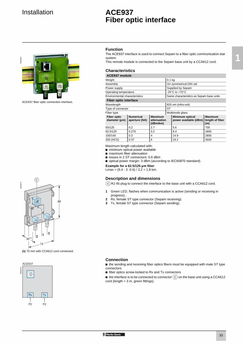
Installation ACE937 Fiber optic interface
FunctionThe ACE937 interface is used to connect Sepam to a fiber optic communication star system.This remote module is connected to the Sepam base unit by a CCA612 cord. P
E50
024
ACE937 fiber optic connection interface.
CharacteristicsACE937 module
Weight 0.1 kgAssembly On symmetrical DIN railPower supply Supplied by SepamOperating temperature -25°C to +70°CEnvironmental characteristics Same characteristics as Sepam base units
Fiber optic interfaceWavelength 820 nm (infra-red)Type of connector STFiber type Multimode glassFiber optic diameter (µm)
Numerical aperture (NA)
Maximum attenuation (dBm/km)
Minimum optical power available (dBm)
Maximum length of fiber (m)
50/125 0.2 2.7 5.6 70062.5/125 0.275 3.2 9.4 1800
100/140 0.3 4 14.9 2800200 (HCS) 0.37 6 19.2 2600
Maximum length calculated with:b minimum optical power availableb maximum fiber attenuationb losses in 2 ST connectors: 0.6 dBmb optical power margin: 3 dBm (according to IEC60870 standard).
Example for a 62.5/125 µm fiberLmax = (9.4 - 3 -0.6) / 3.2 = 1.8 km.
DE
5027
3
Description and dimensionsRJ 45 plug to connect the interface to the base unit with a CCA612 cord.
1 Green LED, flashes when communication is active (sending or receiving in progress)..
2 Rx, female ST type connector (Sepam receiving).3 Tx, female ST type connector (Sepam sending).
(1) 70 mm with CCA612 cord connected.
Connectionb the sending and receiving fiber optics fibers must be equipped with male ST type connectorsb fiber optics screw-locked to Rx and Tx connectors
b the interface is to be connected to connector on the base unit using a CCA612 cord (length = 3 m, green fittings).
DE
5027
4
C
C
SEPED303003EN_1-Installation.FM Page 33 Mardi, 24. juin 2003 2:03 14

34
1
Installation ACE909-2RS 232 / RS 485 converter
FunctionThe ACE909-2 converter is used to connect a master/central computer equipped with a V24/RS 232 type serial port as a standard feature to stations connected to a 2-wire RS 485 network.Without requiring any flow control signals, after the parameters are set, the ACE909-2 converter performs conversion, network polarization and automatic dispatching of Modbus frames between the master and the stations by two-way simplex (half-duplex, single-pair) transmission.The ACE909-2 converter also provides a 12 V DC or 24 V DC supply for the distributed power supply of the Sepam ACE949-2 or ACE959 interfaces.The communication settings should be the same as the Sepam and master communication settings.
PE
5003
5
ACE909-2 RS 232 / RS 485 converter.
CharacteristicsMechanical characteristics
Weight 0.280 kgAssembly On symmetrical or asymmetrical DIN rail
Electrical characteristicsPower supply 110 to 220 V AC ±10%, 47 to 63 HzGalvanic isolationbetween power supply and frame, and between power supply and interface supply
2000 Vrms, 50 Hz, 1 min
Galvanic isolationbetween RS 232 and RS 485 interfaces
1000 Vms, 50 Hz, 1 min
Protection by time-delayed fuse 5 mm x 20 mm 1 A rating
Communication and Sepam interface distributed supplyData format 11 bits: 1 start, 8 bits, 1 parity, 1 stopTransmission delay < 100 ns
distributed power supply for Sepam interfaces 12 V DC or 24 V DCMaximum number of Sepam interfaces with distributed supply
12
Environmental characteristics Operating temperature -5°C to +55°C
Electromagnetic compatibility IEC standard Value5 ns fast transient bursts 60255-22-4 4 kV with capacitive
coupling in common mode2 kV with direct coupling in common mode1 kV with direct coupling in differential mode
1 MHz damped oscillating wave 60255-22-1 1 kV common mode0.5 kV differential mode
1.2, 50 µs impulse wave 60255-5 3 kV common mode1 kV differential mode
SEPED303003EN_1-Installation.FM Page 34 Mardi, 24. juin 2003 2:03 14

35
1
Installation ACE909-2RS 232 / RS 485 converter
Description and dimensions
DE
5003
7
Terminal block for RS 232 link limited to 10 m.
Female 9-pin sub-D connector to connect to the 2-wire RS 485 network, with distributed power supply.1 screw-type male 9-pin sub-D connector is supplied with the converter.
Power supply terminal block.
1 Distributed power supply voltage selector switch, 12 V DC or 24 V DC.2 Protection fuse, unlocked by a 1/4 turn.3 Indication LEDs:
b ON/OFF: on if ACE909-2 is energizedb Tx: on if RS 232 sending by ACE909-2 is activeb Rx on: if RS 232 receiving by ACE909-2 is active
4 SW1, parameter setting of 2-wire RS 485 network polarization and line impedance matching resistors
Function SW1/1 SW1/2 SW1/3Polarization at 0 V via Rp -470 Ω ON
DE
5003
8
Male 9-pin sub-D connector supplied with the ACE909-2.
Polarization at 5 V via Rp +470 Ω ON2-wire RS 485 network impedance matching by 150 Ω resistor
ON
5 SW2, parameter setting of asynchronous data transmission rate and format (same parameters as for RS 232 link and 2-wire RS 485 network).
Rate (bauds) SW2/1 SW2/2 SW2/31200 1 1 12400 0 1 14800 1 0 1
9600 0 0 119200 1 1 0
38400 0 1 0
Format SW2/4 SW2/5With parity check 0
DE
5003
9
Without parity check 11 stop bit (compulsory for Sepam) 0
2 stop bits 1
Converter configuration when deliveredb 12 V DC distributed power supplyb 11 bit format, with parity checkb 2-wire RS 485 network polarization and impedance matching resistors activated.
ConnectionRS 232 linkb to 2.5 mm² screw-type terminal block b maximum length 10 mb Rx/Tx: RS 232 receiving/sending by ACE909-2b 0V: Rx/Tx common, do not earth.
2-wire RS 485 link with distributed power supplyb to female 9-pin sub-D connector b 2-wire RS 485 signals: L+, L-b distributed power supply: V+ = 12 V DC or 24 V DC, V- = 0 V.
Power supply b to 2.5 mm² screw-type terminal block b reversible phase and neutralb earthed via terminal block and metal case (ring lug on back of case).
A
B
C
A
B
C
SEPED303003EN_1-Installation.FM Page 35 Mardi, 24. juin 2003 2:03 14

36
1
Installation ACE919CA and ACE919CCRS 485 / RS 485 converters
FunctionThe ACE919 converters are used to connect a master/central computer equipped with an RS 485 type serial port as a standard feature to stations connected to a 2-wire RS 485 network.Without requiring any flow control signals, the ACE919 converters perform network polarization and impedance matching.The ACE919 converters also provide a 12 V DC or 24 V DC supply for the distributed power supply of the Sepam ACE949-2 or ACE959 interfaces.There are 2 types of ACE919:b ACE919CC, DC-poweredb ACE919CA, AC-powered.
PE
5003
6
CharacteristicsMechanical characteristics
Weight 0.280 kgAssembly On symmetrical or asymmetrical DIN rail
ACE919CC RS 485 / RS 485 converter. Electrical characteristics ACE919CA ACE919CCPower supply 110 to 220 V AC
±10%, 47 to 63 Hz24 to 48 V DC ±20%
Protection by time-delayed fuse 5 mm x 20 mm 1 A rating 1 A ratingGalvanic isolationbetween power supply and frame, and between power supply and interface supply
2000 Vrms, 50 Hz,1 min
Communication and Sepam interface distributed supplyData fomat 11 bits : 1 start, 8 bits, 1 parity, 1 stopTransmission delay < 100 ns
Distributed power supply for Sepam interfaces 12 V DC or 24 V DCMaximum number of Sepam interfaces with distributed supply
12
Environmental characteristics Operating temperature -5°C to +55°C
Electromagnetic compatibility IEC standard Value5 ns fast transient bursts 60255-22-4 4 kV with capacitive
coupling in common mode2 kV with direct coupling in common mode1 kV with direct coupling in differential mode
1 MHz damped oscillating wave 60255-22-1 1 kV common mode0.5 kV differential mode
1.2, 50 µs impulse wave 60255-5 3 kV common mode1 kV differential mode
SEPED303003EN_1-Installation.FM Page 36 Mardi, 24. juin 2003 2:03 14

37
1
Installation ACE919CA and ACE919CCRS 485 / RS 485 converters
Description and dimensions
DE
5006
7
Terminal block for 2-wire RS 485 link without distributed power supply.
Female 9-pin sub-D connector to connect to the 2-wire RS 485 network, with distributed power supply.1 screw-type male 9-pin sub-D connector is supplied with the converter.
Power supply terminal block.
1 Distributed power supply voltage selector switch, 12 V DC or 24 V DC.2 Protection fuse, unlocked by a 1/4 turn.3 ON/OFF LED: on if ACE919 is energized.4 SW1, parameter setting of 2-wire RS 485 network polarization and impedance
matching resistors.Function SW1/1 SW1/2 SW1/3
Polarization at 0 V via Rp -470 Ω ON
Polarization at 5 V via Rp +470 Ω ON
DE
5003
8
2-wire RS 485 network impedance matching by 150 Ω resistor
ON
Converter configuration when deliveredb 12 V DC distributed power supplyb 2-wire RS 485 network polarization and impedance matching resistors activated.
Male 9-pin sub-D connector supplied with the ACE919.
Connection2-wire RS 485 link without distributed power supplyb to 2.5 mm² screw-type terminal block b L+, L-: 2-wire RS 485 signals
b Shielding.
2-wire RS 485 link with distributed power supplyb to female 9-pin sub-D connector b 2-wire RS 485 signals: L+, L-b distributed power supply : V+ = 12 V DC or 24 V DC, V- = 0 V.
Power supply b to 2.5 mm² screw-type terminal block b reversible phase and neutral (ACE919CA)b earthed via terminal block and metal case (ring lug on back of case).
DE
5004
0
A
B
C
A
t
B
C
SEPED303003EN_1-Installation.FM Page 37 Mardi, 24. juin 2003 2:03 14

38
1
SEPED303003EN_1-Installation.FM Page 38 Mardi, 24. juin 2003 2:03 14

39
2
Use Contents
User Machine Interfaces 40
Expert UMI - SFT2841 41Presentation 41General screen organization 42Use of the software 44
Advanced UMI 46White keys for current operation 48Blue keys for parameter and protection setting 50Data entry principles 52
Default settings 53
SEPED303003EN_2-UseTDM.fm Page 39 Mardi, 24. juin 2003 2:12 14

40
2
Use User Machine Interfaces
Sepam series 80 includes a front panel or remote UMI with keypad and graphic LCD display which gives access to all the information necessary for local operation and adjustment of Sepam settings.
The UMI on the front panel of Sepam may be completed by an expert UMI comprising the SFT2841 PC software tool, which may be used for all Sepam parameter setting, local operation and customization functions.
The expert UMI comes as a kit, the SFT2841 kit, which includes:b a CD-ROM, withv SFT2841 setting and operation softwarev SFT2826 disturbance recording file display softwareb CCA783 cord, for connection between the PC and the serial port on the front panel of Sepam.
PE
5008
9
SEPED303003EN_2-Use.fm Page 40 Mardi, 24. juin 2003 2:12 14

41
2
Use Expert UMI - SFT2841Presentation
The expert UMI is available on the screen of a PC equipped with the SFT2841 software tool and connected to the RS 232 link on the front panel of Sepam (run in a Windows 95, 98, NT, 2000 or XP environment).All the data used for the same task are grouped in the same screen to facilitate operation. Menus and icons are used for fast, direct access to the data required.
Normal operationb display of all metering and operation datab display of alarm messages with the time of appearance (date, hour, min, s, ms)b display of diagnosis data such as tripping current, number of switchgear operations and cumulative breaking currentb display of all protection and parameter settingsb display of the logic status of inputs, outputs and LEDs.This UMI is the solution suited to occasional local operation, for demanding personnel who require fast access to all the information.
Parameter and protection settings (1)
b display and setting of all the parameters of each protection function on the same pageb control logic parameter setting, parameter setting of general installation and Sepam datab input data may be prepared ahead of time and transferred into the Sepam in a single operation (loading function).
Main functions performed by SFT2841b changing of passwordsb entry of general settings (ratings, integration period, …)b entry of protection settingsb changing of control logic assignmentsb enabling/disabling of functionsb saving of files.
Savingb protection and parameter setting data may be savedb printing of reports is possible as well.This UMI may also be used to retrieve disturbance recording files and display them using the SFT2826 software tool.
Operating assistanceAccess from all screens to a help section containing all the technical information needed to use and commission Sepam.
(1) Modes accessed via 2 passwords (protection setting level, parameter setting level).
PE
5014
9
Example of a measurement display screen.
PE
5015
0
Example of a directional earth fault protection setting screen.
SEPED303003EN_2-Use.fm Page 41 Mardi, 24. juin 2003 2:12 14

42
2
Use Expert UMI - SFT2841General screen organization
A Sepam document is displayed on the screen via a graphic interface that has the conventional Windows features. All the SFT2841 software screens are set up in the same way. They include:1 The title bar, with:
b name of the application (SFT2841)b identification of the Sepam document displayedb corner symbols for window adjustments
2 The menu bar, for access to all the SFT2841 software functions (unavailable functions are dimmed).
3 The toolbar, a group of contextual icons for quick access to the main functions (also accessed via the menu bar).
4 The work zone available to the user, presented in the form of tab boxes.
5 The status bar, with the following information relating to the active document:b alarm onb identification of the connection windowb SFT2841 operating mode, connected or not connectedb type of Sepamb identification of Sepam editedb identification levelb Sepam operating modeb PC date and time.
PE
5015
1
Example of hardware configuration screen.
PE
5015
2
Guided navigationA guided navigation mode is proposed to make it easier to enter all of the Sepam parameter and protection settings. It guides users through all data input screens in the natural order.The sequencing of the screens in guided mode is controlled by clicking on 2 icons in the toolbar3b : to go back to the previous screenb : to go to the next screen.
The screens are linked up in the following order:1. Sepam hardware configuration2. General characteristics3. CT/VT sensors4. CT/VT circuit supervision5. Particular characteristics6. Control logic7. Logic input/output assignments8. Setting screens for the protection functions available, according to the type of Sepam9. Logic equation editor10. Various tabs of the control matrix11. Parameter setting of the disturbance recording function.
Example of general characteristics screen.
On-line helpThe operator may look up on-line help at any time via the "?" command in the menu bar.Acrobat Reader is required for on-line help. It is provided on the CD.
SEPED303003EN_2-Use.fm Page 42 Mardi, 24. juin 2003 2:12 14

43
2
Use Expert UMI - SFT2841General screen organization
Details of the different screens
b identification: entry of the password gives the user access rights to the parameter and protection mode (valid for 5 minutes)
b selection of a new application from a list of application files with factory settings. The file suffix identifies the application. e.g.: "appli.G87" is for a Generator 87 application
b opening of an existing application which, in principle, should be located in the "Sepam" sub-directory of the "SFT2841" directory. A type of application may be selected by choosing the type of file (e.g.: file type *.S80, or *. G87 or *.* to obtain the complete list of files)
b saving of an application: go to the "Sepam" sub-directory of the "SFT2841" directory, and name the file. The application suffix is updated automatically
b configuration and complete or partial printing of the current configuration file
b print preview of the configuration file
b hard-copy of the current screen
b Sepam parameter setting:v "Sepam hardware" tab: hardware configuration.v "General characteristics" tab: setting of the network, remote control and monitoring, password management and Sepam label printing parameterv "CT/VT sensors" tab: configuration of current and voltage sensorsv "CT/VT supervision" tab: implementation and configuration of CT and VT sensor supervisionv "Particular characteristics" tab: parameter setting of transformer, motor/generator rotation speedv "Control logic" tab: parameter setting of the switchgear control, logic discrimination, genset shutdown, de-excitation, load shedding and restart functionsv "Logic I/Os" tab: management of logic input and output assignment
b protection functions:v "Application" tab: overview of the protection functions available in the application with graphical view of the single-line diagram. A double click on a protection function label gives quick access to the setting tabv 1 tab per protection function: setting of the parameters of each protection function, with a mini-matrix for setting of the outputs, LEDs and disturbance recording
v creation of logic equations: see description in "Control and monitoring functions" chapter
b control matrix: used to assign logic outputs, LEDs and messages to information produced by the protection units, logic inputs and logic equations.b this function may also be used to create messages: see "Creation of user messages" on next page
PE
5015
3
Example of tripping contexts screen.
b parameter setting of the disturbance recording function
b (1) Sepam diagnosisv "Diagnosis" tab: general characteristics, software version, fault indicator and Sepam time-settingv "Input, output and LED status" tab: gives status and proposes an output testv "Remote indication status" tab: remote indication status
b (1) main measurementsv "UIF" tab: voltage, current and frequency valuesv "Other" tab: power, energy and rotation speed valuesv "Temperatures" tab
b (1) diagnosisv "Network" tab: unbalance / negative sequence, V-I phase displacement, number of phase and earth trips and total harmonic distortion valuesv "Machine" tab: running hours counter, differential and through current, impedance, I-I’ phase displacement, H3 voltage and thermal overload valuesv "Tripping context" tab: gives the last 5 tripping contexts
b (1) switchgear diagnosis: cumulative breaking current, auxiliary voltage and circuit breaker data
b (1) management of alarms with history and time-tagging
b (1) disturbance recording: this function is used to record analog signals and logical states. See next page for commissioning information
b guided navigation: see previous page
b on-line help: see previous page
(1) These icons are only accessible in "connected to Sepam" mode.
SEPED303003EN_2-Use.fm Page 43 Mardi, 24. juin 2003 2:12 14

44
2
Use Expert UMI - SFT2841Use of the software
Not connected to Sepam mode Connected to Sepam modeSepam parameter and protection settingSepam parameter and protection setting using SFT2841 consists of preparing the Sepam file containing all the characteristics that are specific to the application, a file that is then downloaded into Sepam at the time of commissioning.Operating procedure:b create a Sepam file for the type of Sepam to be set up (the newly created file contains the factory settings of the Sepam parameters and protection functions)b modify the Sepam general settings and protection function settings:v all the data relating to the same function are grouped together in the same screenv it is advisable to enter all the parameters and protection settings in the natural order of the screens proposed by the guided navigation mode.
Entry of parameter and protection settingsb the parameter and protection setting input fields are suited to the type of value:v choice buttonsv numerical value input fieldsv dialogue box (Combo box)b the user must "Apply" or "Cancel" the new values entered before going on to the following screen b the consistency of the new values applied is checked:v an explicit message identifies inconsistent values and specifies the allowable valuesv values that have become inconsistent following a parameter modification are adjusted to the closest consistent value.
PrecautionWhen a laptop is used, given the risks inherent to the accumulation of static electricity, the customary precaution consists of discharging in contact with an earthed metal frame before physically connecting the CCA783 cord (supplied with the SFT2841 kit).
Plugging into Sepamb plugging of the 9-pin connector (SUB-D type) into one of the PC communication ports.Configuration of the PC communication port via the "Communication port" function in the "Options" menu. b plugging of the 6-pin connector into the connector (round MiniDin type) situated behind the blanking plate on the front panel of Sepam or the DSM303 module.
Connection to Sepam2 possibilities for setting up the connection between SFT2841 and Sepam:b "Connection" function in the "File" menub choice of "connect to the Sepam" at the start-up of SFT2841.Once the connection with Sepam has been established, "Connected" appears in the status bar, and the Sepam connection window may be accessed in the work zone.
User identificationThe window intended for the entry of the 4-digit password is activated:b via the "General characteristics" tab, "Passwords" button…b via the "Identification" function in the "Sepam" menu.The "Return to Operating mode" function in the "Passwords" tab withdraws access rights to the parameter and protection setting mode.
Downloading of parameters and protection settingsParameter and protection setting files may only be loaded in the connected Sepam in Parameter setting mode.Once the connection has been established, the procedure for loading a parameter and protection setting file is as follows:b activate the "Load Sepam" function in the "Sepam" menub select the file (*.S80, *.S81, *.S82, *.T81, *.T82, *.T87, *.M81, *.M87, *.M88, *.G82, *.G87 or *.G88 according to the type of application) which contains the data to be loaded.
Return to factory settingsThis operation is only possible in Parameter setting mode, via the "Sepam" menu. All of the Sepam general settings, protection settings and the control matrix go back to the default values.The return to factory settings does not erase the logic equations. The logic equation editor must be used to delete them.
Unloading of parameter and protection settingsThe connected Sepam parameter and protection setting file may only be unloaded in Operating mode.Once the connection has been established, the procedure for unloading a parameter and protection setting file is as follows:b activate the "Unload Sepam" function in the "Sepam" menub select the *.rpg file that is to contain the unloaded datab acknowledge the end of operation report.
Local operation of SepamConnected to Sepam, SFT2841 offers all the local operating functions available in the advanced UMI screen, plus the following functions:b setting of Sepam’s internal clock, via the "Sepam diagnosis" tabb implementation of the disturbance recording function: enabling/disabling of the function, retrieval of Sepam files, start-up of SFT2826b consultation of the history of the last 250 Sepam alarms, with time-taggingb access to Sepam diagnostic data, in the "Sepam" tab box, included in "Sepam diagnosis"b in Parameter setting mode, switchgear diagnosis values may be modified: operation counter and cumulative breaking current to reset the values after a breaking device is changed.
SEPED303003EN_2-Use.fm Page 44 Mardi, 24. juin 2003 2:12 14

45
2
Use Expert UMI - SFT2841Use of the software
Creation of user messages
This operation is carried out using the control matrix
( icon or "application / set control matrix" menu).
When the matrix is displayed, select the "Events" tab, double-click on the empty box of the message to be created, or on an existing message to modify it. A new screen may be used to:b create a new user message:v click on the "Create messages" buttonb modify the message you have created or an existing user message:v select the message number in the "No." columnv click on the "Modify" buttonv an editing or bitmap window may be used to create text or drawingsb assign the message to the line in the control matrix:v select "message" if it has not already been selectedv select the new predefined or user message in the corresponding "No." columnv click on "Assign"v confirm your choice by clicking on the "OK" button.
PE
5015
4
Example of message creation screen.
Implementation of disturbance recordingDisturbance recording is set up using the icon.Select commissioning.Set the following:b number of recordingsb duration of each recordingb number of samples stored per periodb number of Pretrig periods (number of periods stored before the disturbance recording triggering event).Then make up the list of logic I/Os that should appear in the disturbance recording.If one of the parameters is changed: number of recordings, duration of a recording, number of Pretrig periods, all the recordings already saved will be erased (a warning message is displayed).Changes made in the list of logic I/Os do not affect existing recordings.Click on the "Apply" button.
Disturbance recordings may be displayed by clicking
on the icon.
Each recording is identified in the list by the date.
Manual disturbance recording: click on the "New recording" button and a new dated item appears in the list.
Displaying recordings: select one or more disturbance recordings, and click on the "Retrieve" button.This activates the SFT2826 software for display of the disturbance recording files by selecting the "file" menu / "open" command.
PE
5015
5
Example of disturbance recording configuration screen.
PE
5015
6
Example of disturbance recording display screen.
SEPED303003EN_2-Use.fm Page 45 Mardi, 24. juin 2003 2:12 14

46
2
Use Advanced UMI
Fixed or remote advanced UMIb 2 LEDs indicating Sepam operating status:v green "on" LED: device onv red "wrench" LED: device unavailable (initialization phase or detection of internal failure)b 9 parameterizable yellow LEDs, with a standard label (the SFT2841 software may be used to print personalized labels)b 1 connection port for the RS 232 link with the PC (CCA783 cord), the connector is protected by a sliding cover.b a "graphic" LCD display for the display of measurements, parameter/protection settings and alarm and operating messages.The number of lines, size of characters and symbols are in accordance with the screens and language versions. The LCD display is back-lit when the user presses a key.b a 9-key keypad with 2 operating modes:
White keys for current operation:1 Display of measurements.2 Display of "switchgear, network diagnosis" data.3 Display of alarm messages.4 Resetting.5 Acknowledgment and clearing of alarms.
"LED test" key 6 Switching on sequence of all LEDs.
Blue keys enabled in parameter and protection setting mode:7 Access to protection settings.8 Access to Sepam characteristics.9 Used to enter the 2 passwords required to change
protection and parameter settings The " , , " (4, 5, 6) keys are used to browse through the menus and to scroll and accept the values displayed. "
DE
5052
6
↵ r
r
SEPED303003EN_2-Use.fm Page 46 Mardi, 24. juin 2003 2:12 14

47
2
Use Advanced UMI
Access to operating dataAll of the Sepam operating data may be accessed using the metering, diagnosis, status and protection keys. A first menu is displayed, giving a series of screens for the user to choose from, as shown in the diagram opposite.b the data are split up by category in 4 menus, associated with the following 4 keys:v key: measurementschoices: current, voltage, frequency, power, energyv key: switchgear, network and machine diagnosischoices: diagnosis, tripping contexts (x5)v key: general characteristicsv key: protection settingsb items are chosen from the menus using the cursor keys ( , ), and selected by pressing the key marked b to go on to the next screen, the user presses again on the key of the measurement category displayed. When a screen includes more than 4 lines, the cursor keys ( , ) are used to move from one item to another.
Example: measurement loop
DE
5079
3
Protection and parameter setting modes
MT
1080
8There are 3 levels of use:b operator level: provides read access to all the screens and does not require a passwordb protection setter level: requires the entry of the first password ( key), allows protection setting key)b parameter setter level: requires the entry of the second password ( key). Only parameter setters may modify the passwords. The passwords have 4 digits.
r
r
↵
r
r
Metering numerical values I rms
energizingof Sepam
I0Σ
Average currentclear
Overcurrent
Meteringbar graphs
I0bar graph
clear
Metering menu"current" choice
bar graph
reset
I onon 0 off
clear
passwords
apply cancel
TripextI >> 51I>51 Io >> 51NIo > 51N
SEPED303003EN_2-Use.fm Page 47 Mardi, 24. juin 2003 2:12 14

48
2
Use Advanced UMIWhite keys for current operation
key
MT
1028
3
The "metering" key is used to display the variables measured by Sepam.
key
MT
1111
7
The "diagnosis" key provides access to switchgear, network and machine diagnosis data and tripping contexts to facilitate fault analysis.
key
MT
1028
7
The "alarms" key is used to consult the 16 most recent alarms that have not yet been cleared, in list format or in detail, alarm by alarm.
resetclear
I1 = 162A RMS
I2 = 161A RMS
I3 = 163A RMS
I onextIo >> 51NIo > 51NI> > 51I>51on 0 off Trip
reset
I onon 0 off
clear
ϕ0ϕ1ϕ2ϕ3
= 0˚= -10˚= -11˚= -10˚
TripextI >> 51I>51 Io >> 51NIo > 51N
reset
I onon 0 off
clear
0 Io FAULT-1-2-3
TripextI >> 51I>51 Io >> 51NIo > 51N
SEPED303003EN_2-Use.fm Page 48 Mardi, 24. juin 2003 2:12 14
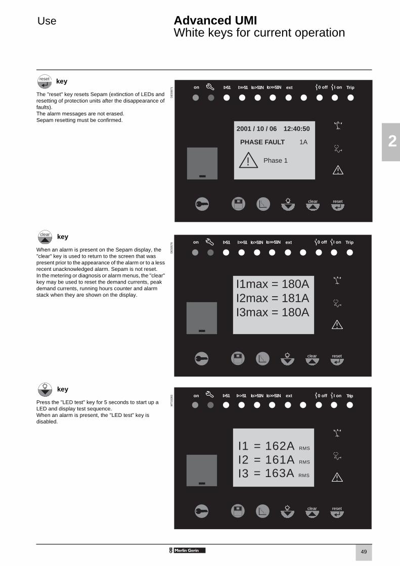
49
2
Use Advanced UMIWhite keys for current operation
key
DE
5087
1
The "reset" key resets Sepam (extinction of LEDs and resetting of protection units after the disappearance of faults). The alarm messages are not erased.Sepam resetting must be confirmed.
key
DE
5057
6
When an alarm is present on the Sepam display, the "clear" key is used to return to the screen that was present prior to the appearance of the alarm or to a less recent unacknowledged alarm. Sepam is not reset.In the metering or diagnosis or alarm menus, the "clear" key may be used to reset the demand currents, peak demand currents, running hours counter and alarm stack when they are shown on the display.
key
MT
1028
3
Press the "LED test" key for 5 seconds to start up a LED and display test sequence.When an alarm is present, the "LED test" key is disabled.
reset
reset
I onon 0 off
clear
2001 / 10 / 06
PHASE FAULT
Phase 1
12:40:50
TripextI >> 51I>51 Io >> 51NIo > 51N
1A
clear
reset
I onon 0 off
clear
I1max = 180AI2max = 181AI3max = 180A
TripextI >> 51I>51 Io >> 51NIo > 51N
resetclear
I1 = 162A RMS
I2 = 161A RMS
I3 = 163A RMS
I onextIo >> 51NIo > 51NI> > 51I>51on 0 off Trip
SEPED303003EN_2-Use.fm Page 49 Mardi, 24. juin 2003 2:12 14

50
2
Use Advanced UMIBlue keys for parameter and protection setting
key
DE
5087
2
The "status" key is used to display Sepam versions and Sepam characteristics.
key
DE
5087
3
The "protection" key is used to display the list of protection functions enabled (via the SFT2841) and the "delay" and "threshold" settings of most of the protection functions.
key
MT
1080
8
The "key" key is used to enter the passwords for access to the different modes:b protection settingb parameter setting.and return to "operating" mode (with no passwords).
Nota : for parameter setting of LEDs and output relays, it is necessary to use the SFT2841 software, "control logic" menu.
reset
I onon 0 off
clear
General settingslanguage setting
modeEnglish TMSFrench 10 I/Is
TripextI >> 51I>51 Io >> 51NIo > 51N
Active group= A
reset
I onon 0 off
clear
50/51
TripCurveThresholdDelay
===
1 A
TripextI >> 51I>51 Io >> 51NIo > 51N
inverse110 A100 ms
reset
I onon 0 off
clear
passwords
apply cancel
TripextI >> 51I>51 Io >> 51NIo > 51N
SEPED303003EN_2-Use.fm Page 50 Mardi, 24. juin 2003 2:12 14

51
2
Use Advanced UMIBlue keys for parameter and protection setting
key
DE
5087
4
The key is used to confirm the protection settings, parameter settings, choice of menu and passwords.
key
DE
5052
5
When there are no alarms on the Sepam display and the user is in the status, protection or alarm menu, the key is used to move the cursor upward.
key
MT
1081
4
When there are no alarms on the Sepam display and the user is in the status, protection or alarm menu, the key is used to move the cursor downward.
reset
reset
I onon 0 off
clear
50/51
TripCurveThresholdDelay
===
SIT550 A600 ms
1 A
TripextI >> 51I>51 Io >> 51NIo > 51N
↵
clear
r
resetclear
I onextIo >> 51NIo > 51NI> > 51I>51on 0 off Trip
Current
Metering
Frequency
Energy
Voltage
Power
r
SEPED303003EN_2-Use.fm Page 51 Mardi, 24. juin 2003 2:12 14

52
2
Use Advanced UMIData entry principles
Use of passwords Entry of parameters and protection settingsSepam has two 4-digit passwords:b the first password, symbolized by a key, is used to modify the protection settingsb the second password, symbolized by two keys, is used to modify the protection settings and all the general settings (using SFT2841).
The 2 factory-set passwords are: 0000
Principle applicable to all Sepam screens(example of phase overcurrent protection)b enter the passwordb press the key the number of times necessary to reach the required screenb move the cursor using the key to access the required field (e.g. curve)b press the key to confirm the choice, then select the type of curve using the key marked or and confirm using the keyb press the key to go to the following fields, until you reach the box marked . Press the key to confirm the setting.
Entry of passwordsPress the key to display the next screen:
Entry of numerical values(e.g. current threshold value).b move the cursor to the required field using the " , " keys and confirm the choice by pressing the key.b the first digit to be entered is selected; set the value using the , keys (choice of . 0……9)b press the key to confirm the choice and go on to the following digit. The values are entered with 3 significant digits and a decimal point. The units (e.g. A or kA) are chosen using the last digit.b press the key to confirm the entry, then press the key for access to the next fieldb all of the values entered are only effective after the user confirms by selecting the
box at the bottom of the screen and presses the key.
MT
1081
6
Press the key to position the cursor on the first digit.
Scroll the digits using the cursor keys ( , ) then confirm to go on to the following digit by pressing the
key. Do not use characters other than numbers 0 to 9 for each of the 4 digits. When the password for your qualification level is entered, press the key to position the cursor on the box marked . Press the key again to confirm. When Sepam is in protection setting mode, a key appears at the top of the display.When Sepam is in parameter setting mode, two keys appear at the top of the display.Access to the protection setting and parameter setting modes is disabled:b by pressing the keyb automatically if no keys are activated for more than 5 minutes.
Modification of passwordsOnly the parameter setting qualification level (2 keys) or the SFT2841 allow modification of the passwords. Passwords are modified in the general settings screen, .key.
Loss of passwordsIf the factory-set passwords have been modified and the latest passwords entered have been irretrievably lost by the user, please contact your local after-sales service representative.
r
reset
r
r
reset
r
applyreset
r
r
reset
r
r
reset
reset
apply reset
apply cancel
passwords
reset
0 X X Xr
r
reset
r
apply reset
SEPED303003EN_2-Use.fm Page 52 Mardi, 24. juin 2003 2:12 14

53
2
Use Default settings
The default settings (or factory settings) are present in Sepam the first time it is used. It is possible to go back to the Sepam default settings at any time by using the "Factory settings" function in the SFT2841 configuration software. These settings are also used to initialize the SFT2841 configuration software setting files.
Parameter Default valueHardware configuration
Model Integrated UMIIdentification Sepam xxxCOM1, COM2 Off
MET148-2 No. 1, 2 OffMSA141 OffMES120 No. 1, 2, 3 Off
General characteristicsFrequency 50 HzIncomer/feeder S80, S81, S82, M81, M87, M88 applications: feeder
G82, G87, G88, T81, T82, T87 applications: incomerPhase rotation direction 1_2_3
Group of settings Group ARemote protection setting enabled OffRemote control with select before operate (SBO)
Off
Integration period 5 min
Active-energy increment 0.1 kWhReactive-energy increment 0.1 kVARhTemperature °C
Sepam working language EnglishTime synchronization mode None
Auxiliary voltage monitoring OffProtection setting password 0000Parameter setting password 0000
CT-VT sensorsSingle-line type 1I - CT rating 5 A
I - Number of CTs I1, I2, I3I – Rated current (In) 630 AI - Base current (Ib) 630 A
I0 – Residual current NoneI'0 – Residual current NoneI' - CT rating 5 A
I' - Number of CTs I1, I2, I3I' – Rated current (I'n) 630 AI' - Base current (I'b) 630 A
V – number of VTs V1V2V3V - Rated primary voltage (Unp) 20 kVV - Rated secondary voltage (Uns) 100 V
V0 3V sumVnt - NoneParticular characteristics
Transformer present T87, G88, M88: yesOther applications: no
Rated voltage Un1 20 kVRated voltage Un2 20 kVRated power 30 MVA
Vector shift 0Rated speed 3000 rpmZero speed threshold 5 %
Pulses per rotation 1Control logic
Switchgear control On, circuit breaker
Logic discrimination OffGenset shutdown OffDe-excitation Off
Load shedding OffRestart OffLogic I/O assignment
O1, O3 On, NO, permanentO2, O5 On, NC, permanentO4 Off
SEPED303003EN_2-Use.fm Page 53 Mardi, 24. juin 2003 2:12 14
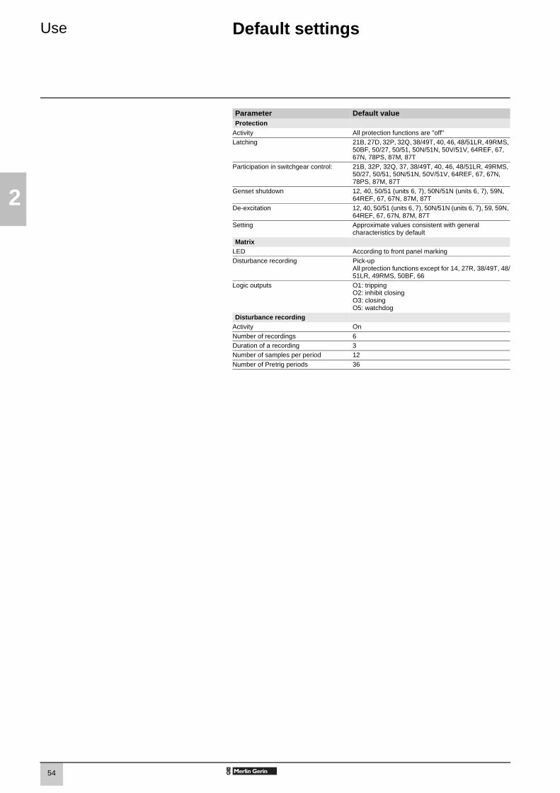
54
2
Use Default settings
Parameter Default valueProtection
Activity All protection functions are "off"Latching 21B, 27D, 32P, 32Q, 38/49T, 40, 46, 48/51LR, 49RMS,
50BF, 50/27, 50/51, 50N/51N, 50V/51V, 64REF, 67, 67N, 78PS, 87M, 87T
Participation in switchgear control: 21B, 32P, 32Q, 37, 38/49T, 40, 46, 48/51LR, 49RMS, 50/27, 50/51, 50N/51N, 50V/51V, 64REF, 67, 67N, 78PS, 87M, 87T
Genset shutdown 12, 40, 50/51 (units 6, 7), 50N/51N (units 6, 7), 59N, 64REF, 67, 67N, 87M, 87T
De-excitation 12, 40, 50/51 (units 6, 7), 50N/51N (units 6, 7), 59, 59N, 64REF, 67, 67N, 87M, 87T
Setting Approximate values consistent with general characteristics by default
MatrixLED According to front panel markingDisturbance recording Pick-up
All protection functions except for 14, 27R, 38/49T, 48/51LR, 49RMS, 50BF, 66
Logic outputs O1: trippingO2: inhibit closingO3: closingO5: watchdog
Disturbance recordingActivity On
Number of recordings 6Duration of a recording 3Number of samples per period 12
Number of Pretrig periods 36
SEPED303003EN_2-Use.fm Page 54 Mardi, 24. juin 2003 2:12 14

55
3
Commissioning Contents
Principles and methods 56
Testing and metering equipment required 57
General examination and preliminary actions 58
Checking of parameter and protection settings 59
Checking of phase current and voltage input connection 60With 3-phase generator 60With single-phase generator and voltages delivered by 3 VTs 62With single-phase generator and voltages delivered by 2 VTs 63
Checking of phase current input connection 64For differential applications 64
Checking of residual current input connection 65
Checking of residual voltage input connection 66With voltage delivered by 3 VTs in open delta arrangement 66With voltage delivered by 1 neutral point VT 67
Checking of residual currentand residual voltage input connection 68
Checking of phase current input connection 69LPCT type current sensors 69
Checking of logic input and output connection and optional module connection 70
Validation of the complete protection chain 71
Test sheet 72Sepam series 80 72
SEPED303003EN_3-CommissioningTDM.fm Page 55 Mardi, 24. juin 2003 2:15 14

56
3
Commissioning Principles and methods
Protection relay testingProtection relays are tested prior to commissioning, with the dual aim of maximizing availability and minimizing the risk of malfunctioning of the assembly being commissioned. The problem consists of defining the consistency of the appropriate tests, keeping in mind that the relay is always involved as the main link in the protection chain.Therefore, protection relays based on electromechanical and static technologies, the performances of which are not totally reproducible, must be systematically submitted to detailed testing, not only to qualify relay commissioning, but also to check that they actually are in good operating order and maintain the required level of performance.
The Sepam concept makes it possible to do away with such testing, since:b the use of digital technology guarantees the reproducibility of the performances announcedb each of the Sepam functions has undergone full factory-qualificationb an internal self-testing system provides continuous information on the state of the electronic components and the integrity of the functions (e.g. automatic tests diagnose the level of component polarization voltages, the continuity of the analog value acquisition chain, non-alteration of RAM memory, absence of settings outside the tolerance range) and thereby guarantees a high level of availability
Sepam is therefore ready to operate without requiring any additional qualification testing that concerns it directly.
Sepam commissioning testsThe preliminary Sepam commissioning tests may be limited to a commissioning check, i.e.:b checking of compliance with BOMs and hardware installation diagrams and rules during a preliminary general checkb checking of the compliance of the general settings and protection settings entered with the setting sheetsb checking of current or voltage input connection by secondary injection testsb checking of logic input and output connection by simulation of input data and forcing of output statusb validation of the complete protection chain (possible customized logical functions included)b checking of the connection of the optional MET148-2 and MSA141 modules.The various checks are described further on.
General principles b all the tests should be carried out with the MV cubicle completely isolated and the MV circuit breaker racked out (disconnected and open)b all the tests are to be performed in the operating situation: no wiring or setting changes, even temporary changes to facilitate testing, are allowed.b the SFT2841 parameter setting and operating software is the basic tool for all Sepam users. It is especially useful during Sepam commissioning tests. The tests described in this document are systematically based on the use of that tool. The commissioning tests may be performed without the SFT2841 software for Sepam units with advanced UMIs.
MethodFor each Sepam:b only carry out the checks suited to the hardware configuration and the functions activated(A comprehensive description of all the tests is given further on)b use the test sheet provided to record the results of the commissioning tests.
Checking of current and voltage input connectionsThe secondary injection tests to be carried out to check the connection of the current and voltage inputs are described according to:b the type of current and voltage sensors connected to Sepam, in particular for residual current and voltage measurementb the type of injection generator used for the tests: three-phase or single-phase generator.The different possible tests are described further on by:b a detailed test procedureb the connection diagram of the associated test generator.The table below specifies the tests to be carried out according to the type of measurement sensors and type of generator used, and indicates the page on which each test is described.
DE
5035
9
For differential applications (2 x 3 CTs), perform the test described on page 64 in addition to the tests for the basic configuration chosen in the chart opposite.
Current sensors Voltage sensors Three-phase generator
Single-phase generator
3 CTs or 3 LPCTs 3 VTs page 60 page 62
3 CTs or 3 LPCTs1 or 2 core bal. CTs
3 VTs page 60page 65
page 62page 65
3 CTs or 3 LPCTs 3 VTs 3 V0 VTs
page 60page 66
page 62page 66
3 CTs or 3 LPCTs1 or 2 core bal. CTs
3 VTs 3 V0 VTs
page 60page 68
page 62page 68
3 CTs or 3 LPCTs 2 phase VTs3 V0 VTs
page 61page 66
page 63page 66
3 CTs or 3 LPCTs1 or 2 core balance CTs
2 phase VTs3 V0 VTs
page 61page 68
page 63page 68
3 CTs or 3 LPCTs 3 VTs 1 neutral pt VT
page 60page 67
page 62page 67
3 CTs or 3 LPCTs1 or 2 core bal. CTs
3 VTs 1 neutral pt VT
page 60pages 65 and 67
page 62pages 65 and 67
3 CTs or 3 LPCTs 2 phase VTs1 neutral pt VT
page 61page 67
page 63page 67
3 CTs or 3 LPCTs1 or 2 core bal. CTs
2 phase VTs1 neutral pt VT
page 61pages 65 and 67
page 63pages 65 and 67
SEPED303003EN_3-Commissioning.FM Page 56 Mardi, 24. juin 2003 2:16 14

57
3
Commissioning Testing and metering equipment required
Generatorsb dual sinusoidal AC current and voltage generator:v 50 or 60 Hz frequency (according to the country)v current adjustable up to at least 5 A rmsv adjustable up to the rated secondary phase-to-phase voltage of the VTsv adjustable relative phase displacement (V, I)v three-phase or single-phase typeb DC voltage generator:v adjustable from 48 to 250 V DC, for adaptation to the voltage level of the logic input being tested.
Accessoriesb plug with cord to match the "current" test terminal box installedb plug with cord to match the "voltage" test terminal box installedb electric cord with clamps, wire grip or touch probes.
Metering devices (built into the generator or separate)b 1 ammeter, 0 to 5 A rmsb 1 voltmeter, 0 to 230 V rmsb 1 phasemeter (if phase displacement (V, I) is not identified on the voltage and current generator).
Computer equipmentb PC with minimal configuration: v MicroSoft Windows 95 / 98 / NT4.0 / 2000 / XPv 133 MHz Pentium processor,v 64 MB of RAM (32 MB with Windows 95 / 98)v 64 MB free on hard diskv CD-ROM driveb SFT2841 softwareb CCA783 serial connection cord between the PC and Sepam.
Documentsb complete connection diagram of Sepam and additional modules, with: v phase current input connection to the corresponding CTs via the test terminal boxv residual current input connectionv phase voltage input connection to the corresponding VTs via the test terminal boxv residual voltage input connection to the corresponding VTs via the test terminal boxv logic input and output connectionv temperature sensor connectionv analog output connectionb hardware BOMs and installation rulesb group of Sepam parameter and protection settings, available in paper format.
SEPED303003EN_3-Commissioning.FM Page 57 Mardi, 24. juin 2003 2:16 14

58
3
Commissioning General examination and preliminary actions
Checking to be done prior to energizingApart from the mechanical state of the equipment, use the diagrams and BOMs provided by the contractor to check:b identification of Sepam and accessories determined by the contractorb correct earthing of Sepam (via terminal 13 of the 20-pin connector and the functional earthing terminal located on the back of the Sepam unit)b correct connection of auxiliary voltage (terminal 1: positive polarity; terminal 2: negative polarity)b presence of the DPC (detection of plugged connectors) bridge on terminals 19-20 of the 20-pin connector .b presence of a residual current measurement core balance CT and/or additional modules connected to Sepam, when applicableb presence of test terminal boxes upstream from the current inputs and voltage inputsb conformity of connections between Sepam terminals and the test terminal boxes.
ConnectionsCheck that the connections are tightened (with equipment non-energized).The Sepam connectors must be correctly plugged in and locked.
Energizing Switch on the auxiliary power supply. Check that Sepam performs the following initialization sequence, which lasts approximately 6 seconds:b green ON and red indicators onb red indicator offb pick-up of "watchdog" contact.The first screen displayed is the phase current measurement screen.
Implementation of the SFT2841 software for PCb start up the PCb connect the PC RS 232 serial port to the communication port on the front panel of Sepam using the CCA783 cordb start up the SFT2841 software, by clicking on the related iconb choose to connect to the Sepam to be checked.
Identification of Sepam b note the Sepam serial number given on the label stuck to the right side plate of the base unitb note the references defining the type of application indicated on the adhesive label on the Sepam cartridgeb note the Sepam type and software version using the SFT2841 software,"Sepam Diagnosis" screenb enter them in the test sheet.
E
E
SEPED303003EN_3-Commissioning.FM Page 58 Mercredi, 25. juin 2003 4:14 16

59
3
Commissioning Checking of parameter and protection settings
Determination of parameter and protection settingsAll of the Sepam parameter and protection settings are determined ahead of time by the design department in charge of the application, and should be approved by the customer.It is presumed that the study has been carried out with all the attention necessary, or even consolidated by a network coordination study. All of the Sepam parameter and protection settings should be available at the time of commissioning:b in paper file format (with the SFT2841 software, the parameter and protection setting file for a Sepam may be printed directly) b and, when applicable, in the format of a file to be downloaded into Sepam using the SFT2841 software.
Checking of parameters and protection settingsCheck to be made when the Sepam parameter and protection settings have not been entered or downloaded during commissioning testing, to confirm the conformity of the parameter and protection settings entered with the values determined during the study. The aim of this check is not to confirm the relevance of the parameter and protection settings.b go through all the parameter and protection setting screens in the SFT2841 software, in the order proposed in guided modeb for each screen, compare the values entered in the Sepam with the values recorded in the parameter and protection setting fileb correct any parameter and protection settings that have not been entered correctly, proceeding as indicated in the SFT2841 section of the Use chapter of this manual.
ConclusionOnce the checking has been done and proven to be conclusive, as of that phase, the parameter and protection settings should not be changed any further and are considered to be final.In order to be conclusive, the tests which follow must be performed with these parameter and protection settings; no temporary modification of any of the values entered, with the aim of facilitating a test, is permissible.
SEPED303003EN_3-Commissioning.FM Page 59 Mardi, 24. juin 2003 2:16 14

60
3
Commissioning Checking of phase current and voltage input connectionWith 3-phase generator
Procedure Connect the 3-phase voltage and current generator to the corresponding test terminal boxes, using the plugs provided, according to the appropriate diagram in terms of the number of VTs connected to Sepam.
Block diagram with 3 VTs connected to Sepam
DE
5070
6
SEPED303003EN_3-Commissioning.FM Page 60 Mardi, 24. juin 2003 2:16 14

61
3
Commissioning Checking of phase currentand voltage input connectionWith 3-phase generator
Block diagram with 2 VTs connected to Sepam
DE
5070
7
b turn the generator onb apply the 3 generator voltages V1-N, V2-N and V3-N, balanced and set to the rated secondary phase-to-neutral voltage of the VTs (i.e. Vns = Uns/3)b inject the 3 generator currents I1, I2 and I3, balanced and set to the rated secondary current of the CTs (i.e. 1 A or 5 A) and in phase with the voltages applied (i.e. generator phase displacement:α1(V1-N, I1) = α2(V2-N, I2) = α3(V3-N, I3) = 0°) b use the SFT2841 software to check the following:v the value indicated for each of the phase currents I1, I2 and I3 is approximately equal to the rated primary current of the CTsv the value indicated for each of the phase-to-neutral voltages V1, V2 and V3 is approximately equal to the rated primary phase-to-neutral voltage of the VT(Vnp = Unp/3)v the value indicated for each phase displacement ϕ1(V1, I1), ϕ2(V2, I2) andϕ3(V3, I3) between currents I1, I2 or I3 and voltages V1, V2 or V3 respectively is approximately equal to 0°b turn the generator off.
SEPED303003EN_3-Commissioning.FM Page 61 Mardi, 24. juin 2003 2:16 14
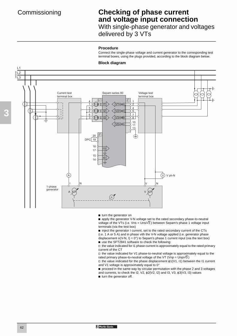
62
3
Commissioning Checking of phase currentand voltage input connection With single-phase generator and voltages delivered by 3 VTs
ProcedureConnect the single-phase voltage and current generator to the corresponding test terminal boxes, using the plugs provided, according to the block diagram below.
Block diagram
DE
5070
8
b turn the generator onb apply the generator V-N voltage set to the rated secondary phase-to-neutral voltage of the VTs (i.e. Vns = Uns/3) between Sepam’s phase 1 voltage input terminals (via the test box) b inject the generator I current, set to the rated secondary current of the CTs(i.e. 1 A or 5 A) and in phase vith the V-N voltage applied (i.e. generator phase displacement α(V-N, I) = 0°) to Sepam’s phase 1 current input (via the text box)b use the SFT2841 software to check the following:v the value indicated for I1 phase current is approximately equal to the rated primary current of the CTv the value indicated for V1 phase-to-neutral voltage is approximately equal to the rated primary phase-to-neutral voltage of the VT (Vnp = Unp/3)v the value indicated for the phase displacement ϕ1(V1, I1) between the I1 current and V1 voltage is approximately equal to 0°b proceed in the same way by circular permutation with the phase 2 and 3 voltages and currents, to check the I2, V2, ϕ2(V2, I2) and I3, V3, ϕ3(V3, I3) valuesb turn the generator off.
SEPED303003EN_3-Commissioning.FM Page 62 Mardi, 24. juin 2003 2:16 14

63
3
Commissioning Checking of phase currentand voltage input connection With single-phase generator and voltages delivered by 2 VTs
DescriptionCheck to be carried out when the voltages are supplied by a 2 VT assembly, with the VT primary circuits connected between phases of the distributed voltage, which means that the residual voltage is obtained outside Sepam (by 3 VTs connected via their secondary circuits in an open delta arrangement) or, when applicable, is not used for the protection function.
Procedure Connect the single-phase voltage and current generator to the corresponding test terminal boxes, using the plugs provided, according to the block diagram below.
Block diagram
DE
5070
9
b turn the generator onb apply (via the test box) the voltage delivered at the V-N terminals of the generator, set to 3/2 times the rated secondary phase-to-phase voltage of the VTs(i.e. 3 Uns/2) between terminals 1-2 of Sepam’s voltage inputs b inject the generator I current, set to the rated secondary current of the CTs(i.e. 1 A or 5 A) and in phase with the V-N voltage applied (i.e. generator phase displacement α(V-N, I) = 0°) to Sepam’s phase 1 current input (via the test box) b use the SFT2841 software to check the following:v the value indicated for I1 phase current is approximately equal to the rated primary current of the CT (Inp)v the value indicated for V1 phase-to-neutral voltage is approximately equal to the rated primary phase-to-neutral voltage of the VT (Vnp = Unp/3)v the value indicated for the phase displacement ϕ1(V1, I1) between the I1 current and V1 voltage is approximately equal to 0°
b proceed in the same way to check the I2, V2, ϕ2(V2, I2) values:v apply the generator V-N voltage set to 3Uns/2 in parallel between terminals 1-2 and 4-2 of Sepam’s voltage inputs (via the test box) v inject an I current set to 1 A or 5 A and in phase opposition with the V-N voltage(i.e. α(V-N, I) = 180°) to Sepam’s phase 2 current input (via the test box) v obtain I2 ≅ Inp, V2 ≅ Vnp = Unp/3 and ϕ2 ≅ 0°. In the absence of residual voltage, V3 = 0, U32 = 3Unp/2b check the I3, V3, ϕ3(V3, I3) values as well: v apply the generator V-N voltage set to 3Uns/2 between terminals 4-2 of Sepam’s voltage inputs (via the test box) v inject a current equal to 1 A or 5 A and in phase with the V-N voltage (i.e. α(V-N, I) = 0°) to Sepam’s phase 3 current input (via the test box)v obtain I3 ≅ Inp, V3 ≅ Vnp = Unp/3 and ϕ3 ≅ 0°. In the absence of residual voltage, V3 = 0, U32 = 3Unp/2b turn the generator off.
SEPED303003EN_3-Commissioning.FM Page 63 Mercredi, 25. juin 2003 4:14 16

64
3
Commissioning Checking of phase current input connectionFor differential applications
DescriptionCheck to be carried out for differential applications (machine, transformer or transformer-machine unit). This test is carried out along with checking of the phase current and phase voltage input wiring. The purpose is to check the wiring of the second Sepam current input.
ProcedureConnect the generator current terminals to the corresponding current test terminal boxes using the plugs provided, according to the block diagram below
Block diagram
DE
5071
0
DE
5035
9
b turn the generator onb inject, in series, into the phase 1 current input terminals of each Sepam connector , connected in opposition (via the test boxes, according to the diagram above), current I from the generator, set to match the CT rated secondary current (1 A or 5 A)b use the SFT2841 software to check the following:v the value indicated for phase current I1 is approximately equal to the rated primary current of the CT (In) wired to the Sepam connectorv the value indicated for phase current I’1 is approximately equal to the rated primary current of the CT (I’n) wired to the Sepam connectorv the value indicated for the phase displacement θ(I, I’) between currents I1 and I’1 is equal to 0° b check the I2 and I’2, I3 and I’3 and θ(I, I’) values as well the values between I2-I’2 and I3-I’3 after transferring the injection plugs to the phase 2 current and then phase 3 current input terminals of each of the Sepam connectorsb turn the generator off.
Should the secondary circuits of the CTs connected to each of the Sepam current inputs not have the same ratings (1 and 5 A or 5 and 1 A), set the injection to the lowest secondary rating. The value indicated for the phase currents (I1, I2, I3) or (I’1, I’2, I’3), as the case may be, is then equal to the CT rated primary current divided by 5 (In/5).
B1 B2
B1
B2
SEPED303003EN_3-Commissioning.FM Page 64 Mardi, 24. juin 2003 2:16 14

65
3
Commissioning Checking of residual current input connection
DescriptionCheck to be carried out when the residual current is measured by a specific sensor such as:b CSH120 or CSH200 core balance CTb CSH30 interposing ring CT (whether it is installed on the secondary circuit of a single 1 A or 5 A CT which encompasses the 3 phases, or on the neutral connection of the three 1 A or 5 A phase CTs)b other core balance CT connected to an ACE990 interface,b and when the residual voltage is calculated in Sepam or cannot be calculated (e.g.: assembly with 2 VTs connected via their primary circuits) and is therefore not available for the protection function.
Procedureb connect according to the diagram below:v a wire between the generator current terminals to inject current into the primary circuit of the core balance CT or CT, with the wire passing through the core balance CT or CT in the P1-P2 direction, with P1 the busbar end and P2 the cable endv when applicable, the generator voltage terminals to the voltage test terminal box, so as to only supply Sepam’s phase 1 voltage input and therefore obtain a residual voltage V0 = V1.
Block diagramNote: the number of CTs connected to the Sepam current connector phase inputs is given as an example and is not used for the test.
DE
5071
1D
E50
359
b turn the generator onb when applicable, apply a V-N voltage set to the rated secondary phase-to-neutral voltage of the VT (i.e. Vns = Uns/3)b inject an I current set to 5 A, and when applicable in phase with the V-N voltage applied (i.e. generator phase displacement α(V-N, I) = 0°)b use the SFT2841 software to check the following:v the value indicated for the measured I0 residual current is approximately equal to 5 Av when applicable, the value indicated for calculated V0 residual voltage is approximately equal to the rated primary phase-to-neutral voltage of the VTs(i.e. Vnp = Unp/3)v when applicable, the value indicated for the phase displacement ϕ0(V0, I0) between the I0 current and V0 voltage is approximately equal to 0°b use the same procedure if the I’0 input is connected. When this is the case, the phase displacement angle to be checked is ϕ’0(V0, I’0), between the I’0 current and V0 voltageb turn the generator off.
Sepam series 80 is equipped with 2 independent residual current inputs which may be connected to a core balance CT installed on the cables, tank earthing cable or neutral point of a transformer, or on the earthing cable of a motor or generator. In some cases, reading of the ϕ0 or ϕ’0 angle is impossible due to the position of the core balance CT (e.g. transformer neutral point or tank earthing cable) or because only one of the two I0 or V0 measurements is necessary or possible. When this is the case, simply check the measured residual current value I0 or I’0.
SEPED303003EN_3-Commissioning.FM Page 65 Mardi, 24. juin 2003 2:16 14
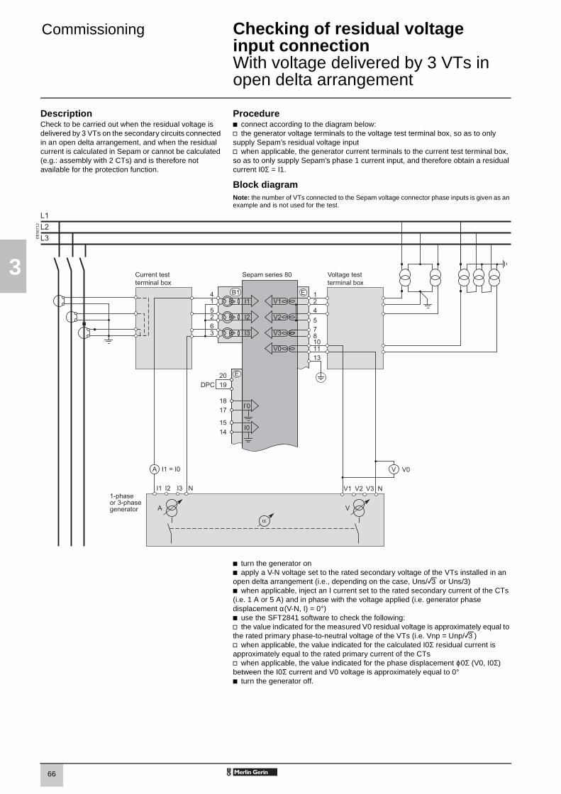
66
3
Commissioning Checking of residual voltage input connectionWith voltage delivered by 3 VTs in open delta arrangement
DescriptionCheck to be carried out when the residual voltage is delivered by 3 VTs on the secondary circuits connected in an open delta arrangement, and when the residual current is calculated in Sepam or cannot be calculated (e.g.: assembly with 2 CTs) and is therefore not available for the protection function.
Procedureb connect according to the diagram below:v the generator voltage terminals to the voltage test terminal box, so as to only supply Sepam’s residual voltage inputv when applicable, the generator current terminals to the current test terminal box, so as to only supply Sepam’s phase 1 current input, and therefore obtain a residual current I0Σ = I1.
Block diagramNote: the number of VTs connected to the Sepam voltage connector phase inputs is given as an example and is not used for the test.
DE
5071
2
b turn the generator onb apply a V-N voltage set to the rated secondary voltage of the VTs installed in an open delta arrangement (i.e., depending on the case, Uns/3 or Uns/3)b when applicable, inject an I current set to the rated secondary current of the CTs (i.e. 1 A or 5 A) and in phase with the voltage applied (i.e. generator phase displacement α(V-N, I) = 0°)b use the SFT2841 software to check the following:v the value indicated for the measured V0 residual voltage is approximately equal to the rated primary phase-to-neutral voltage of the VTs (i.e. Vnp = Unp/3)v when applicable, the value indicated for the calculated I0Σ residual current is approximately equal to the rated primary current of the CTsv when applicable, the value indicated for the phase displacement ϕ0Σ (V0, I0Σ) between the I0Σ current and V0 voltage is approximately equal to 0°b turn the generator off.
SEPED303003EN_3-Commissioning.FM Page 66 Mardi, 24. juin 2003 2:16 14
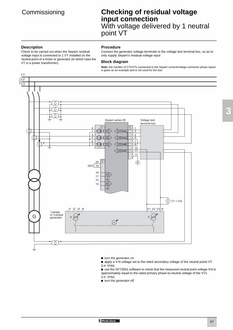
67
3
Commissioning Checking of residual voltageinput connectionWith voltage delivered by 1 neutral point VT
DescriptionCheck to be carried out when the Sepam residual voltage input is connected to 1 VT installed on the neutral point of a motor or generator (in which case the VT is a power transformer).
ProcedureConnect the generator voltage terminals to the voltage test terminal box, so as to only supply Sepam’s residual voltage input
Block diagramNote: the number of CTs/VTs connected to the Sepam current/voltage connector phase inputs is given as an example and is not used for the test.
DE
5071
3
b turn the generator onb apply a V-N voltage set to the rated secondary voltage of the neutral pointt VT (i.e. Vnts)b use the SFT2841 software to check that the measured neutral point voltage Vnt is approximately equal to the rated primary phase-to-neutral voltage of the VTs (i.e. Vnts)b turn the generator off.
SEPED303003EN_3-Commissioning.FM Page 67 Mardi, 24. juin 2003 2:16 14

68
3
Commissioning Checking of residual currentand residual voltage input connection
DescriptionCheck to be carried out when the residual voltage is delivered by 3 VTs on the secondary circuits connected in an open delta arrangement and when the residual current is obtained by a specific sensor such as:b CSH120 or CSH200 core balance CTb CSH30 interposing ring CT (whether it is installed on the secondary circuit of a single 1 A or 5 A CT which encompasses the 3 phases, or on the neutral connection of the three 1 A or 5 A phase CTs)b other core balance CT connected to an ACE990 interface.
Procedureb connect according to the diagram below:v the generator voltage terminals to the voltage test terminal box using the plug provided,v a wire between the generator current terminals to inject current into the primary circuit of the core balance CT or CT, with the wire passing through the core balance CT or CT in the P1-P2 direction, with P1 the busbar end and P2 the cable end.
Block diagramNote: the number of CTs/VTs connected to the Sepam current/voltage connector phase inputs is given as an example and is not used for the test.
DE
5071
4D
E50
359
b turn the generator onb apply a V-N voltage set to the rated secondary voltage of the VTs connected in an open delta arrangement (i.e. Uns/3 or Uns/3)b inject an I current set to 5 A, and in phase with the voltage applied (i.e. generator phase displacement α(V-N, I) = 0°)b use the SFT2841 software to check the following:v the value indicated for the measured I0 residual current is approximately equal to 5 Av the value indicated for the measured V0 residual voltage is approximately equal to the rated primary phase-to-neutral voltage of the VTs (i.e. Vnp = Unp/3)v the value indicated for the phase displacement ϕ0(V0, I0) between the I0 current and V0 voltage is approximatelyequal to 0°b use the same procedure if the I’0 input is connected. When this is the case, the phase displacement angle to be checked is ϕ’0(V0, I’0), between the I’0 current and V0 voltageb turn the generator off.
Sepam series 80 is equipped with 2 independent residual current inputs which may be connected to a core balance CT installed on the cables, tank earthing cable or neutral point of a transformer, or on the earthing cable of a motor or generator. In some cases, reading of the ϕ0 or ϕ’0 angle is impossible due to the position of the core balance CT (e.g.: transformer tank earthing cable or neutral point) or because only one of the two I0 or V0 measurements is necessary or possible. When this is the case, simply check the measured residual current valueI0 or I’0.
SEPED303003EN_3-Commissioning.FM Page 68 Mardi, 24. juin 2003 2:16 14

69
3
Commissioning Checking of phase current input connectionLPCT type current sensors
Reminderb The 3 LPCT current sensors are connected via an RJ45 plug to the CCA671 connector which is to be mounted on the rear panel of Sepam, identified as. and/orb The rated primary current In measured by the LPCT sensors is to be entered as a Sepam general setting and configured by microswitches on the CCA671 connector.
Note: the connection of only one or two LPCT sensors is not allowed and causes Sepam to go into the fail-safe position.
Possible combinations of types of sensorsThe combinations possible depend directly on the type of Sepam application.b Sepam units without ANSI 87T or 87M differential protection functions measure 2 or 3 phase currents by means of sensors wired to connectorb Sepam M87 and G87 units with ANSI 87M machine differential protection measure 2 x 3 phase currents:v 3 CTs or 3 LPCTs at the circuit breaker end wired to connectorv 3 CTs or 3 LPCTs wired to connector b Sepam T87, M88 and G88 units with ANSI 87T transformer differential protection measure 2 x 3 phase currents by means of 2 sets of 3 current transformers:v 3 CTs at the circuit breaker end wired to connectorv 3 CTs wired to connector .
Sensors connected
Sepam without ANSI 87M or 87T
Sepamwith ANSI 87M
Sepamwith ANSI 87T
To connector 2 CTs or 3 CTsto CCA630or 3 LPCTs to CCA671
3 CTs to CCA630or 3 LPCTs to CCA671
3 CTs to CCA630
To connector 3 CTs to CCA630or 3 LPCTs to CCA671
3 CTs to CCA630
ProcedureThe tests to be carried out to check phase current input connections are the same whether the phase currents are measured by CTs or LPCT sensors. Only the Sepam current input connection procedure and current injection values change.To test current inputs connected to LPCT sensors with a standard injection box, the ACE917 injection adapter is required.The ACE917 adapter is inserted between:b the standard injection boxb the LPCT test plug:v integrated in the Sepam CCA671 connectorv or transferred by means of the CCA613 accessory.The ACE917 injection adapter should be set according to the currents selected on the CCA671 connector using the 8-position thumbwheel switch which gives the 8 possible microswitch settings.The injection value depends on the rated primary current selected on the CCA671 connector and entered in the Sepam general settings, i.e.:b 1 A for the following values (in Amps): 25, 50, 100, 133, 200, 320, 400, 630b 5 A for the following values (in Amps): 125, 250, 500, 666, 1000, 1600, 2000, 3150
B1B2
B1
B1B2
B1B2
B1
B2
SEPED303003EN_3-Commissioning.FM Page 69 Mardi, 24. juin 2003 2:16 14

70
3
Commissioning Checking of logic input and output connection and optional module connection
Checking of logic input connection
PE
5014
6
ProcedureProceed as follows for each input:b if the input supply voltage is present, use an electric cord to short-circuit the contact that delivers logic data to the inputb if the input supply voltage is not present, apply a voltage supplied by the DC voltage generator to the terminal of the contact linked to the chosen input, being sure to comply with the suitable polarity and levelb observe the change of status of the input using the SFT2841 software, in the "Input, output, indicator status" screenb at the end of the test, if necessary, press the SFT2841 Reset key to clear all messages and deactivate all outputs.
SFT2841: input, output, indicator status.
Checking of logic output connection
PE
5014
7
ProcedureCheck carried out using the "Output relay test" function, activated via the SFT2841 software, in the "Sepam Diagnosis" screen. Only output O5, when used for the watchdog, can be tested.This function requires prior entry of the "Parameter setting" password.b activate each output relay using the buttons in the SFT2841 softwareb the activated output relay changes status over a period of 5 secondsb observe the change of status of the output relay through the operation of the related switchgear (if it is ready to operate and is powered), or connect a voltmeter to the terminals of the output contact (the voltage cancels itself out when the contact closes)b at the end of the test, press the SFT2841 Reset key to clear all messages and deactivate all outputs.
SFT2841: output relay test.
Checking of optional module connectionChecking of RTD inputs to the MET148-2 moduleThe temperature monitoring function provided by Sepam T81, T82, T87, M81, M87, M88, G82, G87, G88 units checks the connection of each RTD that is configured.An "RTD FAULT" alarm is generated whenever one of the RTDs is detected as being short-circuted or disconnected (absent).To identify the faulty RTD or RTDs:b display the temperature values measured by Sepam using the SFT2841 softwareb check the consistency of the temperatures measured:v the temperature displayed is "****" if the RTD is short-circuited (T < -35 °C)v the temperature displayed is "-****" if the RTD is disconnected (T > 205 °C).
Checking of analog output connection to the MSA141 moduleb identify the measurement associated by parameter setting to the analog output using the SFT2841 softwareb simulate, if necessary, the measurement linked to the analog output by injectionb check the consistency between the value measured by Sepam and the indication given by the device connected to the analog output.
SEPED303003EN_3-Commissioning.FM Page 70 Mardi, 24. juin 2003 2:16 14

71
3
Commissioning Validation of the complete protection chain
PrincipleThe complete protection chain is validated during the simulation of a fault that causes tripping of the breaking device by Sepam.
Procedureb select one of the protection functions that triggers tripping of the breaking device and separately, according to their incidence in the chain, the function or functions related to the programmed or reprogrammed parts of the program logicb according to the selected function or functions, inject a current and/or apply a voltage that corresponds to a faultb observe the tripping of the breaking device and the operation of the adapted parts of the program logic.
At the end of all the voltage and current application type checks, put the covers back on the test terminal boxes.
SEPED303003EN_3-Commissioning.FM Page 71 Mardi, 24. juin 2003 2:16 14

72
3
Commissioning Test sheetSepam series 80
Project: Type of Sepam
Switchboard: Serial number
Cubicle: Software version V
Overall checksCheck off the box v when the check has been made and been conclusiveType of check
Preliminary general examination, prior to energizing vEnergizing vParameter and protection settings vLogic input connection vLogic output connection vValidation of the complete protection chain vValidation of the customized logical functions vAnalog output connection to the MSA141 module vTemperature sensor input connection to the MET148-2 module(for types T81, T82, T87, M81, M87, M88, G82, G87, G88)
v
Checking of phase current and voltage inputsCheck off the box v when the check has been made and been conclusiveType of check Test performed Result Display
Phase current and phase voltage input connection
Secondary injection of CT rated current into ,i.e. 1 A or 5 A
Rated primary current of CTs connected to
I1 = .................... vI2 = .................... vI3 = .................... v
Secondary injection of phase voltage (the value to be injected depends on the test being performed)
VT rated primary phase-to-neutral voltage Unp/3
V1 =................... vV2 =................... vV3 =................... v
Phase displacement ϕ(V, I) ≅ 0° ϕ1 = ................... vϕ2 = ................... vϕ3 = ................... v
Connection of current inputs for differential applications
Secondary injection of CT rated current into / ,i.e. 1 A or 5 A(1 A if secondary ratings are different)
Primary In (or In/5) of CTs connected to (depending on secondary ratings)
I1 = .................... vI2 = .................... vI3 = .................... v
Primary I’n (or I’n/5) of CTs connected to (depending on secondary ratings)
I’1 = ................... vI’2 = ................... vI’3 = ................... v
Phase displacement θ(I, I’) ≅ 0° θ(I1, I’1) = .......... vθ(I2, I’2) = .......... vθ(I3, I’3) = .......... v
Tests performed on: .....................................................................
By:...................................................................................................
Signatures
Comments: ......................................................................................................................................................................................................
.........................................................................................................................................................................................................................................................................................................
......................................................................................................................................................................................................
B1 B1
B1 B2 B1
B2
SEPED303003EN_3-Commissioning.FM Page 72 Mardi, 24. juin 2003 2:16 14

73
3
Commissioning Test sheetSepam series 80
Project: Type of Sepam
Switchboard: Serial number
Cubicle: Software version V
Overall checksCheck off the box v when the check has been made and been conclusiveType of check Test performed Result Display
Residual current input connection
Injection of 5 A into the core balance CT primary circuit
Injected current value I0and/or I’0
I0 =.................... vI’0 = ................... v
When applicable,secondary injectionof the rated phase-to-neutral voltage of a phase VTUns/3
VT rated primary phase-to-neutral voltage Unp/3
V0 = .................. v
Phase displacement ϕ0(V0, I0)and/or ϕ’0(V0, I’0) ≅ 0°
ϕ0 =................... vϕ’0 =.................. v
Residual voltage inputconnectionTo 3 VTs in open delta arrangement
Secondary injectionof the rated voltage of the VTs in an open delta arrangement (Unp/3or Unp/3)
VT rated primary phase-to-neutral voltage Unp/3
V0 = .................. v
When applicable, secondary injection of CT rated current, i.e. 1 A or 5 A
CT rated primary current I0Σ =.................. v
Phase displacement ϕ0Σ(I0, I0Σ) ϕ0Σ = ................ v
To 1 neutral point VT Secondary injectionof the rated voltageof the neutral point VT (Vnts)
VT rated primary phase-to-neutral voltage Vntp
Vnt = ................. v
Residual current and residual voltage input connection
Injection of 5 A into the core balance CT primary circuit
Injected current value I0and/or I’0
I0 =.................... vI’0 = ................... v
Secondary injection of the rated voltage of the VTs in an open delta arrangement (Unp/3 or Unp/3)
VT rated primary phase-to-neutral voltage Unp/3
V0 = .................. v
Phase displacement ϕ0(V0, I0)and/or ϕ’0(V0, I’0) ≅ 0°
ϕ0 =................... vϕ’0 =.................. v
Tests performed on: .....................................................................
By: ...................................................................................................
Signatures
Comments: ......................................................................................................................................................................................................
......................................................................................................................................................................................................
......................................................................................................................................................................................................
SEPED303003EN_3-Commissioning.FM Page 73 Mardi, 24. juin 2003 2:16 14

74
3
SEPED303003EN_3-Commissioning.FM Page 74 Mardi, 24. juin 2003 2:16 14

75
4
Maintenance Contents
Troubleshooting assistance 76
SEPED303003EN_4-MaintenanceTDM.fm Page 75 Mardi, 24. juin 2003 2:19 14

76
4
Maintenance Troubleshooting assistance
Nothing happens when Sepam is switched onAll LEDs off.Nothing displayed on advanced UMI screen.
There is probably an auxiliary power fault.Possible cause Action / remedy
Connector A not plugged in. Plug in connector A.Connectors A and E reversed. Put connectors in correct positions.Auxiliary power absent. Check the auxiliary power level
(range = 24 V DC to 250 V DC).Polarities reversed on terminals 1 and 2of connector A.
Check that the + polarity is on terminal 1and the – polarity on terminal 2.Correct if necessary.
Internal problem. Change base unit.
Fault message on advanced UMI: MAJOR fault: Sepam is in fail-safe positionb ON LED on advanced UMI on
b LED on integrated advanced UMI steadily on
b LED on remote advanced UMI flashing
b green LED on rear panel onb red LED on rear panel steadily on.
PE
5013
9
Connection cannot be made with SFT2841Possible cause Action / remedy
Memory cartridge absent. Switch off Sepam.Install the memory cartridge and secure itby tightening the 2 integrated screws.Switch Sepam on again.
Major faults are only cleared after the cause of the fault is corrected and Sepam is switched on again.
Major internal fault. Change base unit.
Connection can be made with SFT2841Possible cause Action / remedy
The hardware configuration is incorrect or incomplete
Use the SFT2841 software, in connected mode, to determine the cause.The SFT2841 Diagnosis screen displays the missing items in red:
Diagnosis screen Possible cause Action / remedyCCA630 or CCA671 connector in B1 or B2 position displayed in red.
Connector absent. Install a connector.If the connector is present, check that it is plugged in correctly and held in placeby the 2 screws.
LPCT sensors not connected. Connect the LPCT sensors.Connector in position E displayed in red.
Connector E unplugged or no jumper between terminals 19 and 20.
Plug in the connector correctly.Fit the jumper.
MES120 module in H1, H2 or H3 position displayed in red.
MES120 module absent. Install MES120 module.If the MES120 module is present, check that it is plugged in correctly and held in place by the 2 screws. If the fault is still present, replace the module.
SFT2841 indicates major fault, but no missing module.
Base unit internal fault. Change base unit.
1
SEPED303003EN_4-Maintenance.fm Page 76 Mardi, 24. juin 2003 2:19 14

77
4
Maintenance Troubleshooting assistance
MINOR fault: Sepam is operating in downgraded modeb ON LED on advanced UMI on
b LED on remote advanced UMI flashing
b green LED on rear panel onb red LED on rear panel flashing.
Fault message on advanced UMI: Inter-module link fault
PE
5013
9
Possible cause Action / remedyFaulty wiring. Check remote module connections: RJ45
plugs of CCA77x cords clipped correctly into sockets.
Fault message on advanced UMI: MET148 module not available
PE
5013
9
LEDs Possible cause Action / remedyMET148 green and red LEDs off.
Faulty wiring. Check module connections: RJ45 plugs of CCA77x cords clipped correctly into sockets
MET148 green LED on.MET148 red LED off.
No response from MET148 module.
Check the positionof the module numberselection jumper:b MET1 for first MET148-2module(temperatures T1 to T8)b MET2 for second MET148-2module(temperatures T9 to T16).b If the jumper position needs to be changed, reboot the MET148 module(by disconnecting and reconnecting the interconnection cord).
MET148 red LED flashing. Faulty wiring, MET148 powered but loss of dialogue with base unit.
Check module connections: RJ45 plugs of CCA77x cords clipped correctly into sockets.If the MET148 module is the last in the chain, check that the line terminating jumper is in the Rc position. In all other cases, the jumper should be in the position marked .
MET148 red LED steadily on. More than 3 remote modules connected to connector D1 or D2 on base unit.
Distribute remote modules between D1 and D2.
MET148 module internal fault. Change MET148 module.
Fault message on advanced UMI: MSA141 module not available
PE
5013
9
LEDs Possible cause Action / remedyMSA141 green and red LEDs off.
Faulty wiring, MSA141 not powered.
Check module connections: RJ45 plugs of CCA77x cords clipped correctly into sockets.
MSA141 green LED on.MSA141 red LED flashing.
Faulty wiring, MET141 powered but loss of dialogue with base unit.
Check module connections: RJ45 plugs of CCA77x cords clipped correctly into sockets.If the MSA141 module is the last in the chain, check that the line terminating jumper is in the Rc position. In all other cases, the jumper should be in the position marked .
MSA141 red LED steadily on. More than 3 remote modules connected to connector D1 or D2 on base unit.
Distribute remote modules between D1 and D2.
MSA141 module internal fault. Change MSA141 module.
2
3
Rc
4
Rc
SEPED303003EN_4-Maintenance.fm Page 77 Mardi, 24. juin 2003 2:19 14

78
4
Maintenance Troubleshooting assistance
Faulty advanced UMI moduleb ON LED on advanced UMI on
b LED on advanced UMI steadily on
b advanced UMI display offb green LED on rear panel onb red LED on rear panel flashing.
Faulty advanced UMI modulePossible cause Action / remedy
Module internal fault Remote advanced UMI module: replace DSM303 module.
Integrated advanced UMI module: replace base unit.
Alarms"METx FAULT" message.RTD faultPossible cause Action / remedy
An RTD on the MET148 module (x = 1 or 2) is disconnected or short-circuited.
Since the alarm is common to the 8 channels of the module, go the temperature measurement display screen to determine which channel is affected by the fault.Measurement displayed:Tx.x = -**** = RTD disconnected (T > 205 °C)Tx.x = -**** = RTD short-circuited (T < -35 °C)
"BATTERY LOW" message.
.
Battery faultPossible cause Action / remedy
Battery low (or absent) Replace the battery by a 1/2AA format 3.6 V, 0.8 Ah lithium battery, being careful to match the polarities.The recommended batteries are:b SAFT model LS14250b SONNENSCHEIN model SL-350/S.Dead batteries are to be disposed of via an authorized and approved circuit .
SEPED303003EN_4-Maintenance.fm Page 78 Mardi, 24. juin 2003 2:19 14

79
4
Notes
SEPED303003EN_4-Maintenance.fm Page 79 Mardi, 24. juin 2003 2:19 14

80
4
Notes
SEPED303003EN_4-Maintenance.fm Page 80 Mardi, 24. juin 2003 2:19 14


Schneider Electric Industries SASPostal address:Communication Distribution Electrique38050 Grenoble cedex 9 - FranceTel : +33 (0)4 76 57 60 60
http://www.schneider-electric.comhttp://www.sepamrelay.comhttp://www.schneider-electric.co
As standards, specifications and designs change from time to time, please ask for confirmation of the information given in this publication.
This document has been printed on ecological paper.
Design: AmegPublication: Schneider ElectricPrinted:
06-2003ART.52388
SE
PE
D30
3003
EN
© 2
003
Sch
neid
er E
lect
ric -
All
right
res
erve
d
SEPED303003EN_cover.fm Page 3 Vendredi, 27. juin 2003 7:21 07