Operation Manual 030-5670A - Harvest Tec
32
1 030-5670A-OPR 11/13 Operation Manual 030-5670A Touch Screen Display (TSD) for 600 Series
Transcript of Operation Manual 030-5670A - Harvest Tec

1
030-5670A-OPR
11/13
Operation Manual
030-5670A Touch Screen Display (TSD) for 600 Series
Forage Harvester

2
(intentionally blank)

3
Harvest Tec Touch Screen Display Table of Contents 5670A
PAGE Introduction 4 Safety 4 Descriptions of Screens and Menus 5-10 Automatic mode 6 Manual mode 7 Diagnostics 8 Setup mode 9-10 Job records 11 First Time and Annual Startup Instructions Checking and Priming the Pumps (if equipped with applicator)
12 12
Setting up Application and Bale Parameters 13-14 Application Rate 13 Selecting High or Low Tips 13 Baling Parameters 14 Operating Instructions 15-19 Automatic mode 15 Manual mode 16 Job records 17-18 Diagnostics 19 Winter Storage Status Alerts
20 20
Harness and Wiring Installation and Diagram Pin Outs for Harnesses and wiring Diagram Common Questions Troubleshooting
21 22-23
24 25-26
Parts Breakdown 27 Touch Screen Display Kit 27 Notes Warranty statement
4
Introduction
Thank you for purchasing a Harvest Tec Model 5670A Touch Screen Display (TSD). The TSD connects to the 696 Hay Preservative Applicator System in the event the baler processor does not meet ISO 11783 specifications or should you choose to view all preservative functions separate from the ISOBUS Monitor on a dedicated monitor. The 696 Hay Preservative Applicator System is designed to apply buffered propionic acid to the forage crop as it is baled. The 696 applicator will adjust the rate of application based on moisture and tonnage of the crop being harvested. This manual will take you through the steps of operation for the applicator and also point out safety precautions to follow while using the applicator. Please read this manual carefully to learn how to operate the equipment correctly. Failure to do this can result in personal injury or equipment malfunction. If you are unsure about operating the system after consulting this manual, contact your local authorized dealership for additional assistance. If you are in need of parts for the system please see your Installation Manual and contact your local authorized dealer to order the parts. This applicator is designed to apply Harvest Tec buffered propionic acid. Right and Left sides of the baler are determined by facing in the direction of forward travel.
Safety Carefully read all the safety signs in this manual and on the applicator before use. Keep signs clean and visible. Replace missing or damaged safety signs. Replacement signs are available from your local authorized dealer. See your installation manual under the replacement parts section for the correct part numbers. Keep your applicator in proper working condition. Unauthorized modifications to the applicator may impair the function and/or safety of the machine. Carefully read and understand all of the baler safety signs before installing or servicing the baler. Always use the supplied safety equipment on the baler to service the applicator.
5
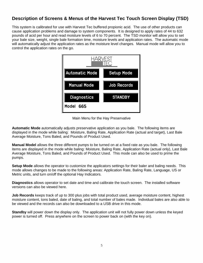
Description of Screens & Menus of the Harvest Tec Touch Screen Display (TSD)
This system is calibrated for use with Harvest Tec buffered propionic acid. The use of other products can cause application problems and damage to system components. It is designed to apply rates of 44 to 632 pounds of acid per hour and read moisture levels of 6 to 70 percent. The TSD monitor will allow you to set your bale size, weight, single bale formation time, moisture levels and application rates. The automatic mode will automatically adjust the application rates as the moisture level changes. Manual mode will allow you to control the application rates on the go.
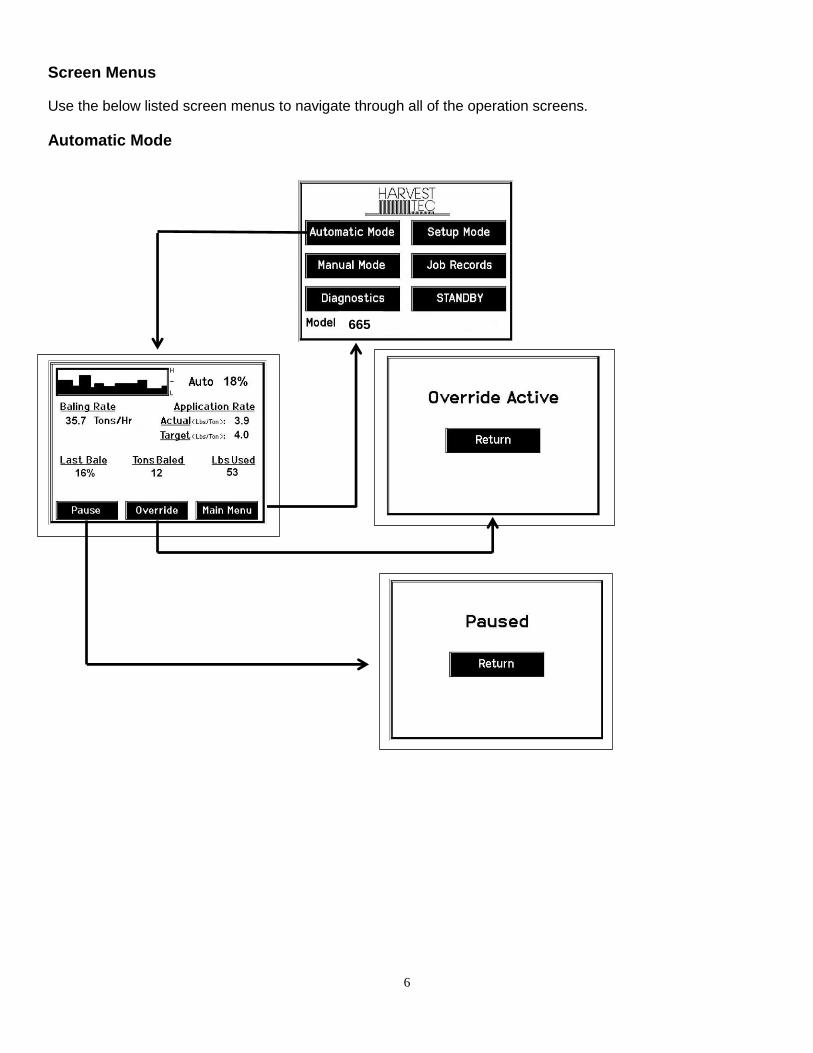
Automatic Mode automatically adjusts preservative application as you bale. The following items are displayed in the mode while baling: Moisture, Baling Rate, Application Rate (actual and target), Last Bale Average Moisture, Tons Baled, and Pounds of Product Used. Manual Model allows the three different pumps to be turned on at a fixed rate as you bale. The following items are displayed in the mode while baling: Moisture, Baling Rate, Application Rate (actual only), Last Bale Average Moisture, Tons Baled, and Pounds of Product Used. This mode can also be used to prime the pumps. Setup Mode allows the operator to customize the applicators settings for their baler and baling needs. This mode allows changes to be made to the following areas: Application Rate, Baling Rate, Language, US or Metric units, and turn on/off the optional Hay Indicators. Diagnostics allows operator to set date and time and calibrate the touch screen. The installed software versions can also be viewed here. Job Records keeps track of up to 300 plus jobs with total product used, average moisture content, highest moisture content, tons baled, date of baling, and total number of bales made. Individual bales are also able to be viewed and the records can also be downloaded to a USB drive in this mode. Standby will power down the display only. The application unit will not fully power down unless the keyed power is turned off. Press anywhere on the screen to power back on (with the key on).
Main Menu for the Hay Preservative
665
6
Screen Menus
Use the below listed screen menus to navigate through all of the operation screens.
Automatic Mode
665

7
Manual Mode
665
8
Diagnostics
\
665
Version

9
Setup Mode
665
Module

10
Setup Mode continued:
665
(0) Disabled (1) Trimble AgGPS 162 (2) Garmin 16xHVS
Baler Select
Crop Eyes
11
Job Records:
665

12
First Time and Annual Start Up Instructions
Checking and Priming the Pumps (if your system is equipped with preservative applicator)
1. Put 10 gal of water in tank and turn main ball valve on. 2. Inspect for any leaks or drips at this time. If any are found tighten or replace area or fitting. 3. Turn the Main Control ON (turn on key to the tractor). 4. Press the Setup Mode key. Select Sensors are OFF to disable bale rate sensors. Make sure the AVG Bale
Weight is 1500 lbs and the AVG Baler Length is 96 in. and EST Baling Time is 60 sec. Press the Main Menu key to return to the opening screen.
5. Press the Manual Mode key. 6. The screen shown below should appear. 7. The rates listed below are for Harvest Tec buffered propionic acid. Other products will need to be collected and
weighed to assure proper performance is achieved.
8. NOTE: the system comes with the High Output tips already installed on the spray shield. Test the system with the tips you will use most often.
With Low Output tips in: Turn pump 1 on (P1). To do this press the underlined area on the screen which says OFF. The application rate should then read between 1.1 – 1.5 Lbs/Ton. Ideally, at 13.5 volts, the rate would read 1.3 Lbs/Ton.
Repeat the process for pumps 2 and 3 (P2 and P3). The application rate should read between 1.9 – 2.6 Lbs/Ton and 2.9 – 3.9 Lbs/Ton respectively. Ideally, at 13.5 volts, the rate for pump 2 would be 2.2 Lbs/Ton; pump 3 would be 3.4 Lbs/Ton.
With High Output tips in: Turn pump 1 on (P1). To do this press the underlined area on the screen which says OFF. The application rate should then read between 1.9 – 2.6 Lbs/Ton. Ideally, at 13.5 volts, the rate would read 2.2 Lbs/Ton.
Repeat the process for pumps 2 and 3 (P2 and P3). The application rate should read between 2.9 – 3.9 Lbs/Ton and 5.7– 7.7 Lbs/Ton respectively. Ideally, at 13.5 volts, the rate for pump 2 would be 3.4 Lbs/Ton; pump 3 would be 6.7 Lbs/Ton.
9. This process will also be used to prime the pumps whenever needed. 10. While running pumps check for a good spray pattern out of the respective tips and verify that no parts of the
system are leaking. 11. While doing these tests the Volume Used on the bottom of the screen should be counting up. This verifies that
the flow meter is functioning. 12. Last Bale shows the average moisture content of the last bale made. This information will then be saved in your
Job Records. 13. Select the Main Menu key to return to the intial start up screen.
NOTE: It is recommended that the system be run with the Bale Rate Sensors ON. Press the Setup Mode key and turn the Bale Rate Sensors back ON for normal operation. (Also see Baling Rate to adjust bale weight, length, and time.)
8
11
13 12
13
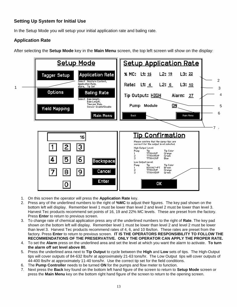
Setting Up System for Initial Use
In the Setup Mode you will setup your initial application rate and baling rate.
Application Rate After selecting the Setup Mode key in the Main Menu screen, the top left screen will show on the display:
1. On this screen the operator will press the Application Rate key. 2. Press any of the underlined numbers to the right of %MC to adjust their figures. The key pad shown on the
bottom left will display. Remember level 1 must be lower than level 2 and level 2 must be lower than level 3. Harvest Tec products recommend set points of 16, 19 and 22% MC levels. These are preset from the factory. Press Enter to return to previous screen.
3. To change rate of chemical application press any of the underlined numbers to the right of Rate. The key pad shown on the bottom left will display. Remember level 1 must be lower than level 2 and level 2 must be lower than level 3. Harvest Tec products recommend rates of 4, 6, and 10 lbs/ton. These rates are preset from the factory. Press Enter to return to previous screen. IT IS THE OPERATORS RESPONSIBILITY TO FOLLOW THE RECOMMENDATIONS OF THE PRESERVATIVE. ONLY THE OPERATOR CAN APPLY THE PROPER RATE.
4. To set the Alarm press on the underlined area and set the level at which you want the alarm to activate. To turn the alarm off set level above 80.
5. Press the underlined area next to Tip Output to cycle between the High and Low sets of tips. The High-Output tips will cover outputs of 84-632 lbs/hr at approximately 21-63 tons/hr. The Low Output tips will cover outputs of 44-400 lbs/hr at approximately 11-40 tons/hr. Use the correct tip set for the field conditions.
6. The Pump Controller needs to be turned ON for the pumps and flow meter to function. 7. Next press the Back key found on the bottom left hand figure of the screen to return to Setup Mode screen or
press the Main Menu key on the bottom right hand figure of the screen to return to the opening screen.
2
4
5
7
3
5
6
7
1
Module
14
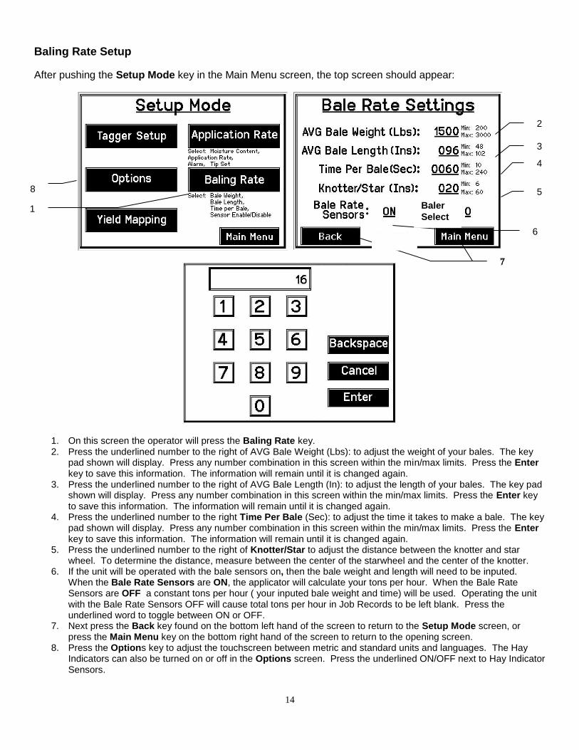
Baling Rate Setup
After pushing the Setup Mode key in the Main Menu screen, the top screen should appear:
1. On this screen the operator will press the Baling Rate key. 2. Press the underlined number to the right of AVG Bale Weight (Lbs): to adjust the weight of your bales. The key
pad shown will display. Press any number combination in this screen within the min/max limits. Press the Enter key to save this information. The information will remain until it is changed again.
3. Press the underlined number to the right of AVG Bale Length (In): to adjust the length of your bales. The key pad shown will display. Press any number combination in this screen within the min/max limits. Press the Enter key to save this information. The information will remain until it is changed again.
4. Press the underlined number to the right Time Per Bale (Sec): to adjust the time it takes to make a bale. The key pad shown will display. Press any number combination in this screen within the min/max limits. Press the Enter key to save this information. The information will remain until it is changed again.
5. Press the underlined number to the right of Knotter/Star to adjust the distance between the knotter and star wheel. To determine the distance, measure between the center of the starwheel and the center of the knotter.
6. If the unit will be operated with the bale sensors on, then the bale weight and length will need to be inputed. When the Bale Rate Sensors are ON, the applicator will calculate your tons per hour. When the Bale Rate Sensors are OFF a constant tons per hour ( your inputed bale weight and time) will be used. Operating the unit with the Bale Rate Sensors OFF will cause total tons per hour in Job Records to be left blank. Press the underlined word to toggle between ON or OFF.
7. Next press the Back key found on the bottom left hand of the screen to return to the Setup Mode screen, or press the Main Menu key on the bottom right hand of the screen to return to the opening screen.
8. Press the Options key to adjust the touchscreen between metric and standard units and languages. The Hay Indicators can also be turned on or off in the Options screen. Press the underlined ON/OFF next to Hay Indicator Sensors.
1
2
3
4
5
6
7 7
8
Baler
Select
15
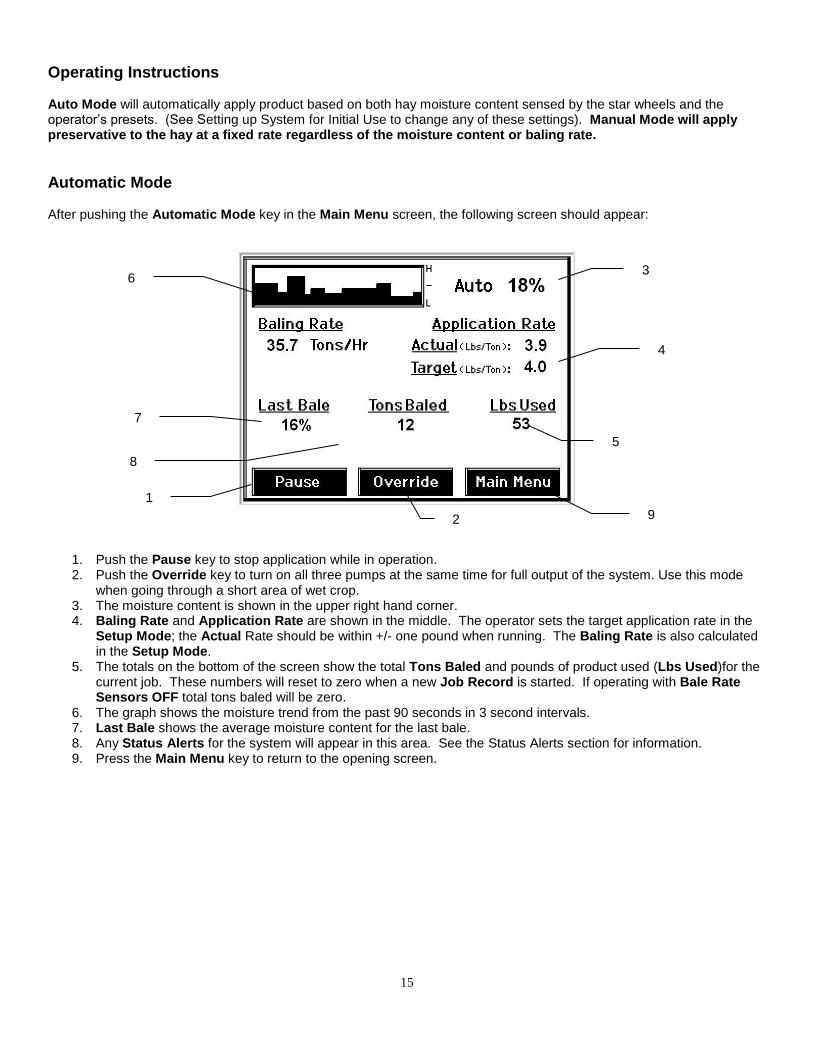
Operating Instructions Auto Mode will automatically apply product based on both hay moisture content sensed by the star wheels and the operator’s presets. (See Setting up System for Initial Use to change any of these settings). Manual Mode will apply preservative to the hay at a fixed rate regardless of the moisture content or baling rate.
Automatic Mode After pushing the Automatic Mode key in the Main Menu screen, the following screen should appear:
1. Push the Pause key to stop application while in operation. 2. Push the Override key to turn on all three pumps at the same time for full output of the system. Use this mode
when going through a short area of wet crop. 3. The moisture content is shown in the upper right hand corner. 4. Baling Rate and Application Rate are shown in the middle. The operator sets the target application rate in the
Setup Mode; the Actual Rate should be within +/- one pound when running. The Baling Rate is also calculated in the Setup Mode.
5. The totals on the bottom of the screen show the total Tons Baled and pounds of product used (Lbs Used)for the current job. These numbers will reset to zero when a new Job Record is started. If operating with Bale Rate Sensors OFF total tons baled will be zero.
6. The graph shows the moisture trend from the past 90 seconds in 3 second intervals. 7. Last Bale shows the average moisture content for the last bale. 8. Any Status Alerts for the system will appear in this area. See the Status Alerts section for information. 9. Press the Main Menu key to return to the opening screen.
1
2
3
4
5
6
9
7
8

16
Manual Mode
After pushing the Manual Mode key in the Main Menu screen, the following screen should appear:
1. Push the Pause key to stop application while in operation. 2. Push the Override key to turn on all three pumps at the same time for full output of the system. Use this mode
when going through a short area of wet crop. 3. In Manual Mode you can turn the pumps on or off by pressing the underlined area next to the pump numbers. In
Manual Mode (regardless of moisture, tons per hour or bale weight) the outputs of the pumps are fixed rates as follows:
Low output tips: High output tips: Pump 1 = 60 LBS/HR Pump 1 = 100 LBS/HR Pump 2 = 100 LBS/HR Pump 2 = 150 LBS/HR Pump 3 = 150 LBS/HR Pump 3 = 300 LBS/HR
4. The moisture content is shown in the upper right hand corner. 5. Baling Rate and Application Rate are shown in the middle. The output of a pump can be checked by dividing
the preset output (shown in step 3) by the baling rate. For example, if you have the high output tips in and are running pump three by itself, your output is 300 lbs/hr. Given the baling rate shown on the above screen (45.0 tons/hr), the application rate should be about 6.7 lbs/ton (300lbs/hr divided by 45.0 tons/hr).
6. The Totals on the bottom of the screen show the total tons (Tons Baled) and pounds (Lbs Used) of product used for the current job. These numbers will reset to zero when a new Job Record is started. If operating with Bale Rate Sensors OFF total tons baled will be zero.
7. The Baling Rate is set in the Setup Mode menu. 8. This graph shows the moisture trend from the last 90 seconds of baling (one reading every 3 seconds). 9. Last Bale shows the average moisture content for the last bale. 10. Press the Main Menu key to return to the opening screen.
1
2
3
4
5
6
7
8
10
9

17
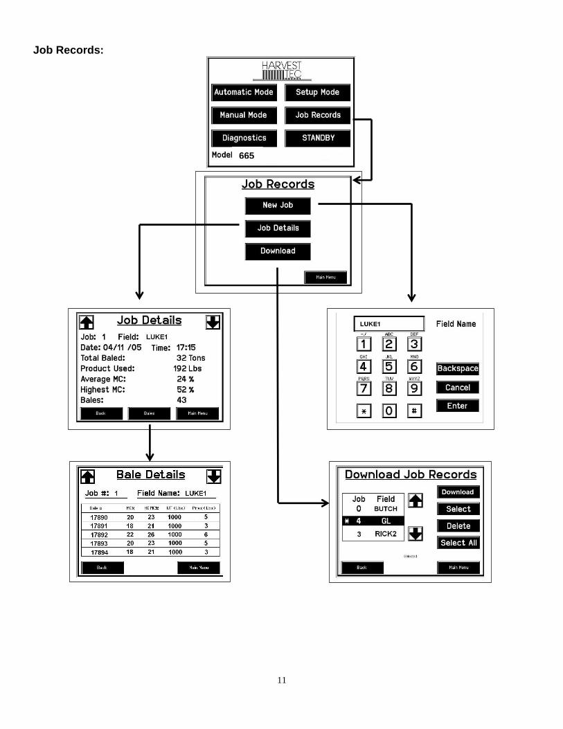
Job Records
After pushing the Job Records key in the Main Menu screen, the following screen should appear.
1. Pressing New Job will save all the previous bale records and open the Field Name screen. 2. Use the key pad in the Field Name screen to enter up to an eight character field name. Use the asterisk key to
move on to the next letter or number if they are identical. Use the pound sign as a space between the characters. When you have completed the field name press enter.
3. Pressing Job Details will open the Job Details screen. Use the up and down arrows to scroll through the different jobs. Job: 0 will always be your current and open job record. Press Back to go to the Job Records screen or Main Menu for the main screen.
4. Pressing Bales on the bottom of the screen will open a Bale Details screen. This screen lets you look at the individual bale records for the first five bales made. Use the up and down arrows to scroll through five bales at a time. Press Back to go to the Job Details screen or Main Menu for the main screen.
Continued on the next page
1
3
5
18
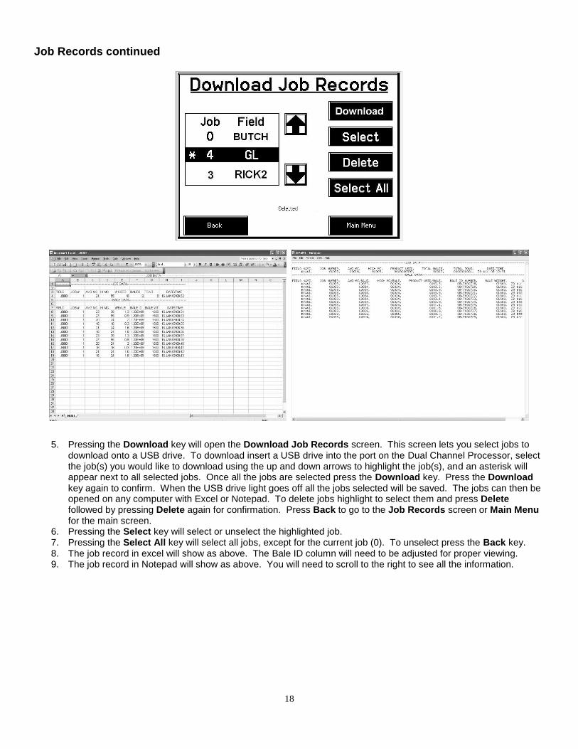
Job Records continued
5. Pressing the Download key will open the Download Job Records screen. This screen lets you select jobs to download onto a USB drive. To download insert a USB drive into the port on the Dual Channel Processor, select the job(s) you would like to download using the up and down arrows to highlight the job(s), and an asterisk will appear next to all selected jobs. Once all the jobs are selected press the Download key. Press the Download key again to confirm. When the USB drive light goes off all the jobs selected will be saved. The jobs can then be opened on any computer with Excel or Notepad. To delete jobs highlight to select them and press Delete followed by pressing Delete again for confirmation. Press Back to go to the Job Records screen or Main Menu for the main screen.
6. Pressing the Select key will select or unselect the highlighted job. 7. Pressing the Select All key will select all jobs, except for the current job (0). To unselect press the Back key. 8. The job record in excel will show as above. The Bale ID column will need to be adjusted for proper viewing. 9. The job record in Notepad will show as above. You will need to scroll to the right to see all the information.

19
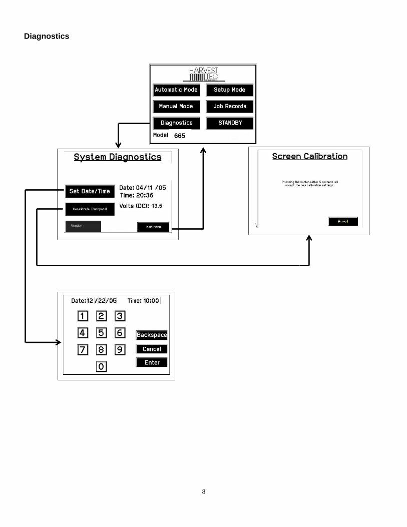
Diagnostics After pushing the Diagnostics key in the Main Menu screen, the following screen should appear:
1. To set date and time, press the Set Date/Time key. In the next screen enter the date (month, day, year format) followed by the time. When done press the Enter key. NOTE: The clock uses military (or 24 hour) time.
2. The voltage should be between 12.0 to 14.5 volts for the system to work properly. If voltage is not in this range check all power cord connections and the tractors charging system.
3. Press the Recalibrate Touchpad key to realign the screen keys to your preference. When the screen appears, follow the directions and press Accept when done.
4. Press the Versions key to check all software versions of modules attached to the DCP. 5. When done in this mode, press the Main Menu key.
1
3
5
2
4
20
Winter Storage
1. Thoroughly flush the system with water. 2. Remove the filter bowl and run dry until the water has cleared out of the intake side. 3. Remove the red plug from the bottom of the pump, drain, and run the pump for 30 seconds or until it is
dry. 4. Drain all lines on the outlet side. 5. Never use oils or alcohol based anti-freeze in the system. 6. For spring start-up, if the pump is frozen, turn off the power immediately to avoid burning the motor out
or blowing a fuse. The pump head can be disassembled and freed or rebuilt in most cases. Check the fuses after the pump has been freed.
7. Disconnect power from the Dual Channel Processor. 8. Remove Touch Screen Display from tractor and store in a warm, dry place.
Status Alerts
Two Status Alerts will appear on the Auto and Manual mode screens when the Job Records are approaching, or full of records. Status Alert “Bale Records: Less than 1K remaining”. The system is now approaching the maximum amount of records that can be saved. When this code appears, download and delete jobs in the Job Records menu. Follow the instructions in Job Records to accomplish this. Status Alert “Bale Records failed – Memory Full”. The system will no longer accept any new data until jobs in the Job Records menu are downloaded and deleted. Follow the instructions in Job Records to accomplish this.

21
Harness/Wiring Installation Tractor Harness Installation for systems using Harvest Tec Touch Screen Display (TSD) Kit (030-5670A)
1. Locate the tractor power/communication harness (006-6650TM). 2. From the back of the tractor run the power leads to the battery and run the communication lead into the
cab of the tractor. 3. Connect the red power wire with the 50 amp fuse to the positive side (12 volt) of the battery.
a. The power harness must be connected to the battery! The unit will draw more amps than convenience outlets can handle. Any modifications of the power harness will void systems warranty. IF MODIFICATIONS ARE REQUIRED CONTACT HARVEST TEC FIRST!
b. This unit will not function on positive ground tractors. c. If the unit loses power while operating it will not keep track of accumulated pounds of
product used and bale records. 4. Connect the black ground wire to frame of tractor or negative side of (12 volt) battery. 5. Attach the orange wire (006-5650K) to the orange wire coming out the back side of the communication
plug on the Communication Harness (006-6650TM). 6. Attach the open end of the orange wire (006-5650K) to the keyed switch outlet in the cab of the tractor. 7. Attach the Harvest Tec display (the TSD)
Keyed Power
Extension
006-5650K
Dual Channel
Processor
(DCP)
006-6671LS
Moisture/Bale Rate
Harness
006-7303H
Proximity Sensor (2X)
006-7303S
Star Wheel
Assembly
(2X)
006-4641
End of Bale Sensor
006-7400
Flow Meter
006-4725A
Optional Port
Pump
Harness
006-4660Z
Pump Controller
006-5672
Terminating Connector
006-5650Z
Pump Controller
Harness
006-5650FM
TSD
006-5670A
Orange
Wire to
Keyed
Power Power/Comm Harness on Baler
006-6650LS2
Power/Comm Harness on Tractor
006-6650TM
Data
Transfer

22
Pin Outs for Harnesses and Wiring Diagrams
Power/Comm Harness 006-6650TM at Hitch Pin 1 Red +12V Power to TSD Pin 2 Red +12V Power to DCP Pin 3 Orange Keyed Power Pin 4 Gray Shield Pin 5 Green HT Can Low Pin 6 Yellow HT Can Hi Pin 7 Orange Can1 Hi Pin 8 Black Ground from TSD Pin 9 Black Ground from DCP Pin 10 Blue Can1 Low Power/Comm Harness 006-6650LSM2 at Hitch Pin 1 Red +12V Power to TSD Pin 2 Red +12V Power to DCP Pin 3 Orange Keyed Power Pin 4 Gray Shield Pin 5 Green HT Can Low Pin 6 Yellow HT Can Hi Pin 7 Orange Can1 Hi Pin 8 Black Ground from TSD Pin 9 Black Ground from DCP Pin 10 Blue Can1 Low Display Plug on Harness 006-6650TM at TSD Pin 1 Red +12V Power from DCP Pin 2 Black Ground from TSD Pin 3 Yellow HT Can Low Pin 4 Gray Shield Pin 5 Green HT Can Hi Pin 6 Orange Can1 Hi Pin 7 Blue Can1 Low Main Power Connector on DCP Pin 1 Red +12V Power from tractor Pin 2 Black Ground from tractor Pin 3 Orange Keyed power Star Wheel and Bale Rate Sensor connector on DCP Pin 1 Blue +12V Power Pin 2 Orange Ground Pin 3 Black Signal for sensor 1 Pin 4 White Signal for sensor 2 Pin 5 N/A Pin 6 N/A Pin 7 N/A Pin 8 Violet Star wheel input 1 Pin 9 Brown Star wheel input 2
1 2
3
4
5
6
7
8
9
10
1 2
3
4
5
6
7
8
9
10
2
1
3
4
5
6
7
23
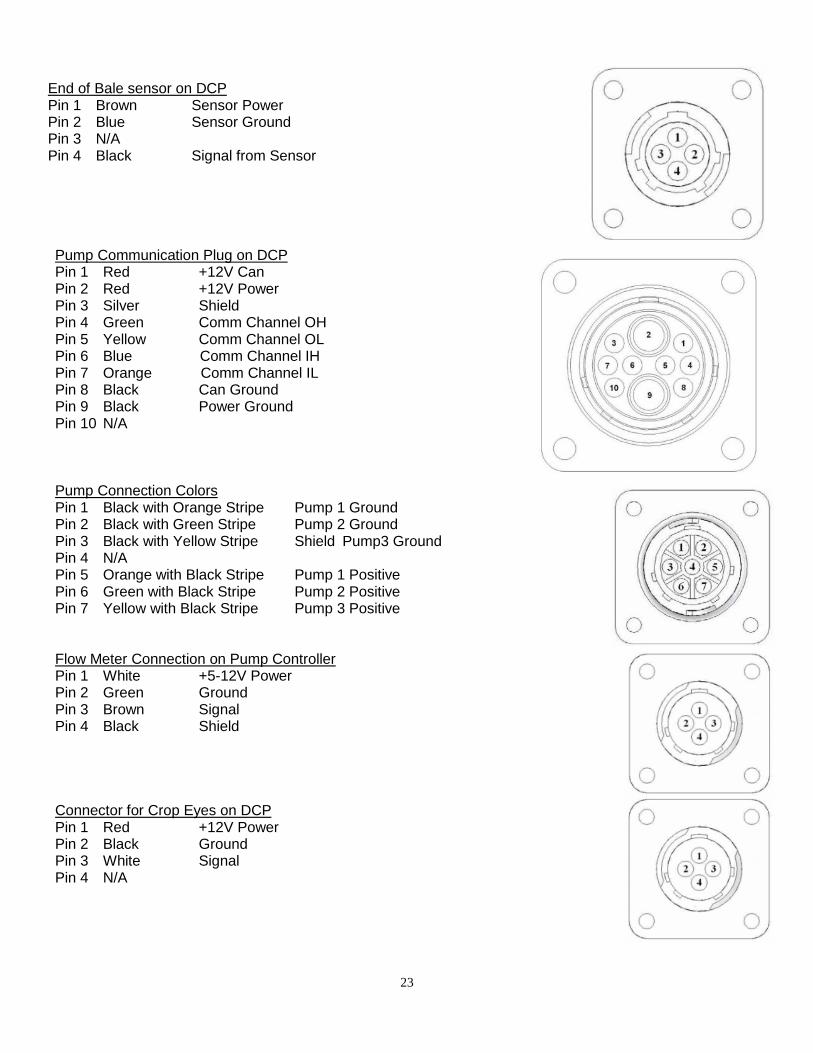
End of Bale sensor on DCP Pin 1 Brown Sensor Power Pin 2 Blue Sensor Ground Pin 3 N/A Pin 4 Black Signal from Sensor
Pump Communication Plug on DCP Pin 1 Red +12V Can Pin 2 Red +12V Power Pin 3 Silver Shield Pin 4 Green Comm Channel OH Pin 5 Yellow Comm Channel OL Pin 6 Blue Comm Channel IH Pin 7 Orange Comm Channel IL Pin 8 Black Can Ground Pin 9 Black Power Ground Pin 10 N/A Pump Connection Colors Pin 1 Black with Orange Stripe Pump 1 Ground Pin 2 Black with Green Stripe Pump 2 Ground Pin 3 Black with Yellow Stripe Shield Pump3 Ground Pin 4 N/A Pin 5 Orange with Black Stripe Pump 1 Positive Pin 6 Green with Black Stripe Pump 2 Positive Pin 7 Yellow with Black Stripe Pump 3 Positive Flow Meter Connection on Pump Controller Pin 1 White +5-12V Power Pin 2 Green Ground Pin 3 Brown Signal Pin 4 Black Shield Connector for Crop Eyes on DCP Pin 1 Red +12V Power Pin 2 Black Ground Pin 3 White Signal Pin 4 N/A
24
Common Questions
1. How do I turn the system on/off? Turn the key in the tractor to the on position. If the unit is in Standby Mode, press anywhere on the screen. To turn off, press the Standby key, wait for the screen to power down and turn off the key.
2. How to get in the LBS/TON, MC%, and TONS/HR menus?
In the Main Menu press the Setup Mode key. From this screen you can change your application rates and how much product is applied. See the section Setting Up the Baler for Initial Use for a detailed explanation of this process.
3. The unit is stuck in the MC% screen.
In the MC% screen, level 1 must be less than level 2, and level 2 must be less than level 3. For example, if level 1 is set at 16, level 2 must be set at 17 or higher, and level 3 must be set higher than level 2.
4. How does Override work?
Override turns on all three pumps at full output. The pumps will remain at full output until the operator turns these pumps off by pressing the Override key again.
5. The flow meter reading is more or less than the programmed level set in the box.
Some variation in flow meter readings compared to the programmed set point is normal due to factory tolerances on the pump motors as well as varying tractor voltages inputted to the control box. The flow meter reading is an accurate measure of how much product is actually being applied. The set points then will need to be adjusted if you want to attain a different flow meter reading.
6. Why don’t all the pumps turn on even at higher application rates?
The selections of what pumps turn on when are automatically controlled by the control box’s flow rate look up chart. Thus, not all the pumps turn on at once and the combination of what pumps turn on when is automatically controlled by the software. If you want to make sure all three pumps are working, go to the Diagnostics screen and run pump outputs.
7. The moisture content displays “LO” or “HI” all the time.
When the moisture content display does not change frequently while baling, there is likely a faulty star wheel connection. One of the first places to check is inside the white star wheel block. Check to see if the electronic swivel is in the star wheel shaft and check to see that the star wheel shaft is not working out of the block. Also, check all star wheel wires and connectors to see if there is a continuity or grounding problem.
8. Should the battery connections be removed before jump starting or charging a battery? Yes. Anytime the tractor will have voltage going up rapidly the connections should be removed.
9. How do I recalibrate the touch screen display? In the system Diagnostics screen press the Recalibrate Touch Screen key and follow the directions on the screen. Press Accept when done.
10. How can I turn the optional Hay Indicators on/off from the cab? In the Setup Mode screen press Options. Press the On/Off underlined area next to Hay Indicator Sensor.
25
Troubleshooting
Problem Possible cause Solution
Pump will not run. 1. No voltage to DCP or Pump controller.
1. Check for short, low voltage, and replace fuse(s) if necessary.
2. Pump locked up. 2. Clean or rebuild pump if motor is OK.
3. Damaged wire. 3. Repair damaged wire.
4. Fuse blown on Pump controller. 4. Replace fuse and check pump for short in wire or locked motor.
Pump runs but will not prime. 1. Air leak in intake. 1. Tighten fittings on intake side.
2. Clogged intake. 2. Clean.
3. Restricted outlet. 3. Check and clean tips.
4. Check valve on the outlet is stuck closed.
4. Clean or repair check valve.
5. Dirt inside pump. 5. Replace pump check valve.
Pump does not develop enough output. 1. Air leaks or clogs on inlet side. 1. Tighten or clean filter bowl assembly.
2. Pump worn or dirty. 2. Rebuild pump.
Moisture reading errors (high or low) 1. Wire disconnected or bad connection between star wheels and DCP
1. Reconnect wire.
2. Low power supply to DCP 2. Check voltage at box. (Min of 12 volts required.) See Diagnostics section of manual.
3. Dry hay lower than 8% or wet hay over 75% moisture
System reads 8-70% moisture
4. Ground contact with one or both star wheels and baler mounted processor.
4. Reconnect.
5. Short in wire between star wheels and DCP.
5. Replace wire.
6. Check hay with hand tester to verify.
6. Contact Harvest Tec if conditions persist.
Moisture readings erratic. 1. Test bales with hand tester to verify that cab monitor has more variation than hand tester.
2. Check all wiring connections for corrosion or poor contact.
2. Apply dielectric grease to all connections.
3. Check power supply at tractor. Voltage should be constant between 12 and 14 volts.
3. Install voltage surge protection on tractors alternator.
Flow meter readings do not match up with product usage.
Product is less than actual product used.
1. Voltage supplied to meter is less than 6 volts.
1. Check for a min of 6 volts supplied at Pump controller.
2. Wiring short in signal to baler mounted processor.
2. Inspect wire and replace if necessary.
3. Clog in meter. 3. Back flush with water. DO NOT USE AIR.
4. Using product other than Harvest Tec
4. Catch and weigh product to check outputs.
Product shown is more than actual product used.
1. High voltage supplied to the meter.
1. Check voltage at Pump controller. Max of 18 volts.
2. Light interference with meter. 2. Reflection into meter can cause a high reading. Move meter or protect from sunlight.
3. Air leak in intake. 3. Look for air bubbles in line. Replace line or other defective area that is

26
allowing air into the system.
4. Using product other than Harvest Tec
4. Catch and weigh product to check outputs.
System leaks product out of tips after shut down.
1. Dirty or defective check valves. 1. Clean or Replace.
Terminal reads under or over power. 1. Verify with mult-meter actual voltage. Voltage range should be between 12-14 volts.
1. Clean connections and make sure applicator is hooked to battery. See Diagnostics section of manual.
System does not pause at the end of a row.
1. Short in cable. 2. Damaged sensor. 3. Bad alignment of sensors
1. Replace cable. 2. Replace sensor 3. Check 474 manual for alignment instructions
Bale rate displays zero. 1. Bale rate sensors are reversed. 2. Short in cable. 3. Damaged sensor. 4. Sensor too far from star wheel
1. Switch the sensors next to the star wheel. 2. Replace cable. 3. Replace sensor. 4. Adjust gap between prox sensor and star wheel so it is 1/8-1/4” away
Display will not power up. 1. Connection broke between the display and the DCP. 2. Short in display cable.
1. Check, clean, and tighten connections. 2. Replace cable.
Display is too dark or light 1. Change in temperature or light conditions.
1. Use the monitors contrast control.
Display is locked up/froze.
1. CAN communication not responding. 2. Broke connection between the display and DCP or Pump control and DCP.
1. Check connections at DCP and Pump controller including the terminating resistors. 2. Check, clean, and tighten connections. 3. Power unit down and restart after steps 1 & 2 are complete.
Display powers up when key is turned and will not go to the Main Menu screen.
1. CAN communication not responding. 2. Broke connection between the display and DCP or Pump control and DCP.
1. Check connections at DCP and Pump controller including the terminating resistors. 2. Check, clean, and tighten connections. 3. Power unit down and restart after steps 1 & 2 are complete.
Display is locked up/froze and pumps continue to run.
1. CAN communication not responding. 2. Broke connection between the display and DCP or Pump control and DCP.
1. Check connections at DCP and Pump controller including the terminating resistors. 2. Check, clean, and tighten connections. 3. Power unit down and restart after steps 1 & 2 are complete.
Display says PAC error 1. The DCP and Pump controller are not communicating. 2. Broke connection between the display and DCP or Pump control and DCP.
1. Check all connections at DCP and Pump controller including terminating resistors. 2. Check, clean, and tighten connections.

27
Parts Breakdown Touch Screen Display (TSD)
1 Touch Screen Display 006-6670 2 Suction Cup Mount 001-2012SCM 3 RAM Mount 001-2012H Complete Kit 030-5670A
1
2
3

28
NOTES

29

30

31
WARRANTY AND LIABILITY AGREEMENT
Harvest Tec, Inc. will repair or replace components that are found to be defective within 12 months from the date of manufacture. Under no circumstances does this warranty cover any components which in the opinion of Harvest Tec, Inc. have been subjected to negligent use, misuse, alteration, accident, or if repairs have been made with parts other than those manufactured and obtainable from Harvest Tec, Inc. Our obligation under this warranty is limited to repairing or replacing free of charge to the original purchaser any part that in our judgment shows evidence of defective or improper workmanship, provided the part is returned to Harvest Tec, Inc. within 30 days of the failure. Parts must be returned through the selling dealer and distributor, transportation charges prepaid. This warranty shall not be interpreted to render Harvest Tec, Inc. liable for injury or damages of any kind, direct, consequential, or contingent, to persons or property. Furthermore, this warranty does not extend to loss of crop, losses caused by delays or any expense prospective profits or for any other reason. Harvest Tec, Inc. shall not be liable for any recovery greater in amount than the cost or repair of defects in workmanship. There are no warranties, either expressed or implied, of merchantability or fitness for particular purpose intended or fitness for any other reason. This warranty cannot guarantee that existing conditions beyond the control of Harvest Tec, Inc. will not affect our ability to obtain materials or manufacture necessary replacement parts. Harvest Tec, Inc. reserves the right to make design changes, improve design, or change specifications, at any time without any contingent obligation to purchasers of machines and parts previously sold. Revised 01/03/06

32
HARVEST TEC, INC. P.O. BOX 63
2821 HARVEY STREET HUDSON, WI 54016
PHONE: 715-386-9100 1-800-635-7468
FAX: 715-381-1792 Email: [email protected]