Operation & Maintenance Manual The Orion Series of ... · Operation & Maintenance Manual The Orion...
99
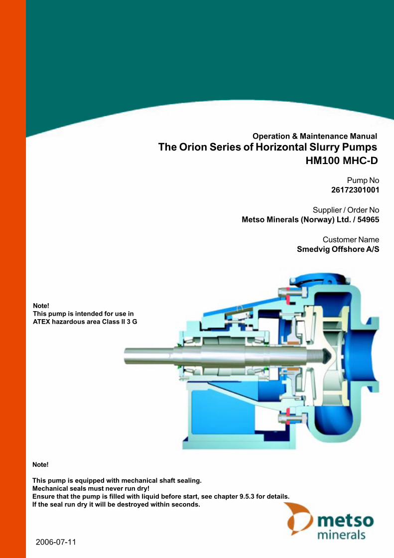
Operation & Maintenance Manual The Orion Series of Horizontal Slurry Pumps HM100 MHC-D Pump No 26172301001 Supplier / Order No Metso Minerals (Norway) Ltd. / 54965 Customer Name Smedvig Offshore A/S 2006-07-11 Note! This pump is equipped with mechanical shaft sealing. Mechanical seals must never run dry! Ensure that the pump is filled with liquid before start, see chapter 9.5.3 for details. If the seal run dry it will be destroyed within seconds. Note! This pump is intended for use in ATEX hazardous area Class II 3 G
Transcript of Operation & Maintenance Manual The Orion Series of ... · Operation & Maintenance Manual The Orion...
Operation & Maintenance ManualThe Orion Series of Horizontal Slurry Pumps
HM100 MHC-D
Pump No 26172301001
Supplier / Order NoMetso Minerals (Norway) Ltd. / 54965
Customer NameSmedvig Offshore A/S
2006-07-11
Note!
This pump is equipped with mechanical shaft sealing.Mechanical seals must never run dry!Ensure that the pump is filled with liquid before start, see chapter 9.5.3 for details.If the seal run dry it will be destroyed within seconds.
Note!This pump is intended for use inATEX hazardous area Class II 3 G

Slurry Pump
ATEXII3Gen_01a.doc JAN 04-W16 ATEX-Supplement 1/2
0 EXPLOSIVE ATMOSPHERE (ATEX) – SUPPLEMENT
0.1 About this supplement The instructions provided in this supplement apply to pumps intended for use in ATEX hazardous areas. They complement the standard instructions presented in the accompanying Operation & Maintenance Manual, but in case of any contradiction, they shall override the latter.
0.2 General information about ATEX ATEX ATEX is not a standard but an acronym for 'ATmosphères
EXplosifs'. It stands for the European Directive 94/9/EC covering the certification procedures for equipment destined for use in hazardous areas.
Explosive atmosphere A mixture of flammable substances in the form of gas, vapour, mist, dust or fibres, and air under atmospheric conditions, in which, after ignition, combustion spreads throughout the unconsumed mixture.
Maximum surface temperature
The highest temperature attained in service, under the most adverse operating conditions expected within the pump equipment rating, by any part or surface of the equipment, that could ignite the surrounding explosive atmosphere.
0.3 Supplementary instructions
0.3.1 Supplement to section 2.1.1 ‘Product signs’ (Chapter 2)
- CE marking - European Commission mark for EX-products - Equipment group: Surface - Equipment category - Gas
Figure 2.1.1-x Machine plate
Slurry Pump
ATEXII3Gen_01a.doc JAN 04-W16 ATEX-Supplement 2/2
0.3.2 Supplement to section 3.1.2 ‘Training’ (Chapter 3) For your own personal safety, read and take note of the following: HAZARDOUS AREAS - This pump is intended for use in areas in which
explosive atmospheres created by gases, vapours, mists or air/dust mixtures are likely to occur.
0.3.3 Supplement to section 5 ‘Control sytem’ (Chapter 5) (NOT APPLICABLE) 0.3.4 Supplement to section 7 ‘Commissioning’ (Chapter 7) 1. Check that the electrical engine is approved for ATEX hazardous area. 2. Ensure that the pump installation is equipped with a level sensor or similar to prevent
it from running dry. 3. BEFORE starting the pump, make sure it is primed. 4. Ensure that the pump pipework is equipped with devices that would prevent high
temperatures, or high pressures, caused by ”closed valve conditions”. 5. Make sure that all other installed equipment is approved for ATEX hazardous area. 6. Check that the pump is properly grounded.
0.3.5 Supplement to section 8.3 ‘Running checks’ (Chapter 8) During pump operation, the following conditions need to be continuously monitored by a control system. NOTE: THE CONTROL SYSTEM IS NOT INCLUDED IN THIS SUPPLY.
• A level system that ensures that the pump never run dry.
0.3.6 Supplement to section 9.2.1 ‘Routine maintenance’ (Chapter 9)
ITEM ACTION RUNNING HOURS Bearing cylinder Check bearing for over-heating 100h
Shaft seal Check for over-heating 100h
Pump/Drive unit installation Check for right pump shaft speed 100h

Slurry Pump
ATEXII3Gen_01a.doc JAN 04-W16 Content 1/2
EXPLOSIVE ATMOSPHERE (ATEX) - SUPPLEMENT
0.1 About this supplement 0.2 General information about ATEX 0.3 Supplementary instructions
1. GENERAL
1.1 About this manual 1.2 Transport and storage 1.3 Pump specification 1.4 Customer service
2. DESCRIPTION
2.1 Product and warning signs 2.2 Applications 2.3 Design 2.4 Materials and maximum working pressures 2.5 Surface treatment 2.6 General arrangement 2.7 Performance curves 2.8 Certificates & test results
3. HEALTH & SAFETY 4. DESCRIPTION OF OPERATION 5. CONTROL SYSTEM 6. INSTALLATION
6.1 General 6.2 Foundation requirements 6.3 Installation tools and equipment 6.4 Installation procedure 6.5 Pipe connections & pump sump 6.6 Shaft gland 6.7 Motor and operation

Slurry Pump
ATEXII3Gen_01a.doc JAN 04-W16 Content 2/2
7. COMMISSIONING 8. OPERATING INSTRUCTIONS
8.1 Starting 8.2 Stopping 8.3 Running checks
9. CARE AND MAINTENANCE
9.1 Safety measures 9.2 Preventive maintenance & service schedule 9.3 Tools and special equipment for service and maintenance 9.4 Lubrication instructions 9.5 Dismantling and assembly
9.5.1 Setting pump clearances 9.5.2 Hydraulic parts and frame - removal and fitting 9.5.3 Shaft seal – removal and refitting 9.5.4 Shaft and bearing assembly - removal and fitting 9.5.5 Shaft and bearings - disassembly and re-assembly 9.5.6 Pump drive - dismantling and reassembling 9.6 Fault tracing schedule
10. SPARE PARTS
10.1 Recommended stock of spares 10.2 Storage of spare parts 10.3 Spare parts ordering procedure 10.4 Spare parts drawing 10.5 Parts list 10.6 Special tools
11. APPENDICES
11.1 Torque table 11.2 Reference publications list 11.3 Weights table

Slurry Pump
WH03AA1AAA0en_03b.doc JAN 04-W08 General 1/6
1 GENERAL
1.1 About this manual This manual is a part of the equipment to which it relates. It is written for the use of installers, commissioning engineers, operators and maintainers. It should be kept for the life of the equipment and, in case of re-sale, passed on to any subsequent purchaser. Information contained in this manual is specific to the equipment and is correct at the date of publication. As improvements are continually being made, Metso Minerals reserve the right to make alterations to the equipment design and specification without giving prior notice. Any amendments issued by Metso Minerals should be promptly inserted into this manual. © 2004 — Metso Minerals (Sala) AB. The contents of this manual must not be reproduced without the prior written permission of Metso Minerals (Sala) AB.
1.2 Transport and storage
1.2.1 Delivery A pump is either dispatched as an individual unit (bare shaft pump) or mounted complete with drive unit on a bedplate (pump-set). In either case, any exposed machined parts are coated with a suitable rust inhibitor. Each pump is supplied complete with inlet and outlet flanges and gaskets, drive key, and with the bearing cylinder charged with grease. The packing or boxing will always be more than adequate for the method of shipment and subsequent storage. On receipt of the pump, check that the items listed on the consignment list have been supplied and have not been damaged in transit. Ensure that the inlet and outlet apertures are clear and that the impeller runs freely when the shaft is turned by hand. If the pump has been disassembled for shipment, a consignment list will contain complete information on the identification of parts. Where parts are boxed, each box is numbered and the corresponding number is noted on the consignment list. If damage has occurred or any items are missing, immediately file a report with the carrier making the delivery. Also, submit a written report to Metso Minerals detailing the damage and/or missing items, as soon as possible.

Slurry Pump
WH03AA1AAA0en_03b.doc JAN 04-W08 General 2/6
1.2.2 Handling and lifting Whether at the depot or on site, ALWAYS follow normal handling and lifting procedures and instructions contained or referred to in this manual. Handling of centrifugal pumps requires great care, especially larger or more cumbersome items of machinery. All slinging, lifting or conveying MUST be carried out by appropriately skilled personnel. Always lift slowly and smoothly, maintaining the pump in a level attitude. For your covenience and safety, approximate weight of the pump, or pump complete with drive unit and baseplate, is in the Appendices, Section 11.
WARNINGS MAKE SURE THAT ALL SLINGS, SHACKLES, ETC. USED ARE OF ADEQUATE LOAD CARRYING CAPACITY FOR THE UNIT TO BE LIFTED. CHECK THAT ALL LIFTING EQUIPMENT CERTIFICATES ARE CURRENT.

Slurry Pump
WH03AA1AAA0en_03b.doc JAN 04-W08 General 3/6
1.2.3 General storage instructions • Re-apply rust inhibitor to all moving parts, at least, every two months.
Protect pump against dust and weather by storage indoors or under weatherproof cover
Protect pump against impact Turn shaft at least every month

Slurry Pump
WH03AA1AAA0en_03b.doc JAN 04-W08 General 4/6
1.2.4 Long-term field storage Minimum requirement for storage and maintenance of centrifugal type pumps on site before their installation and start-up. 1. Medium term storage Indoor storage of equipment is recommended in order to prevent the harmful effects of exposed conditions, particularly in dust laden atmospheres. The standard anti-rust protection provided prior to dispatch remains adequate for periods not exceeding two months. Whenever indoor storage is not possible, it is necessary to follow the guidelines given below:
a) Locate the pump set with its bedplate on a concrete floor and supported on wooden joists of approximately 100 mm x 100 mm in section.
b) Cover the pump set, whether located indoors or outdoors, with a strong, waterproof cover extending down to the baseplate. The cover must be securely fixed to withstand ambient weather conditions.
c) Prior to fitment of the cover, ensure that:- i. all openings, including inlet and outlet apertures, are properly sealed, and; ii. the bearing cylinder and drive are properly protected against dust.
2. Prolonged storage -up to 2 years The following steps are essential in all cases where prolonged storage is foreseen:
a) The pumps are to be adequately warehoused in a closed dry and, if possible, a temperature controlled building.
b) Every six months, the stuffing box/shaft seal sleeve area should be inspected, cleaned and re-coated with a suitable anti-rust compound, if required.
c) If disassembly of the pump is not practical then proceed as follows:- i. Desiccate the pump case with hot air at 35°C to 65°C. ii. Seal all pump openings and attach sachets of hygroscopic salts (silica gel). iii. During the desiccation with hot air, ensure that no other parts become
overheated as this may be detrimental.
d) The pump rotor should be turned over several times by hand at intervals not exceeding one month.
e) The bearing grease should be checked at least once every twelve months. f) The bearing cylinder must be disassembled, cleaned and regreased prior to
reassembly at least once every 24 months.

Slurry Pump
WH03AA1AAA0en_03b.doc JAN 04-W08 General 5/6
During prolonged storage, it may prove difficult to rotate the pump rotor manually for normal maintenance. In such cases proceed as follows:-
a) Loosen the bearing end covers which limit the axial displacement of the bearings.
b) Move the pump rotor along its axis, thus freeing the assembly and allowing manual rotation.
3. Storage in excess of two years For prolonged storage in excess of two years in adverse ambient conditions, special protection may be necessary. Any moisture absorbing devices used must be absolutely effective and regularly maintained. Whenever possible for storage periods in excess of two years, it is recommended that all pump components are disassembled, washed, dried, protected and reassembled afterwards. This work may be done by Metso Minerals and charged to the purchaser under normal rates in force at the time the service is carried out.
1.2.5 Storage of spares In general, unless otherwise instructed, keep all spares parts in a cool, dry environment and protect rubberised/synthetic components from sunlight and high voltage electrical equipment. Rubber is affected by ageing and its rate of deterioration is dependent on the type of rubber and the storage conditions. Rubber perishes most rapidly when exposed to heat, ultra violet light and oxidants. The more commonly overlooked sources of which are sunlight and electrical machinery. Rubber can become permanently deformed if compressed out of shape during storage. Mineral oils, solvents, dust, contact with metals and moisture can also damage rubbers depending on type. Certain types of rubber such as chloroprene rubber (CR) harden at temperatures below +5°C. In conditions of extreme cold these types of rubber harden to such an extent that they could develop cracks and be damaged by handling. Chloroprene rubber does not regain its normal hardness when the ambient temperature rises but has to be reconditioned.

Slurry Pump
WH03AA1AAA0en_03b.doc JAN 04-W08 General 6/6
To ensure rubber products maintain their original properties, storage conditions must be controlled. Where practicable, ensure rubber products are: 1. kept sealed in their original packing which should be opaque; 2. kept away from direct sunlight; 3. kept away from electrical machinery -e.g. motors and generators; 4. kept in a cool, dry environment between 15° C to 25° C; 5. stored away from exhaust fumes; 6. stored separately from chemicals and fuels; 7. stored loosely packed; 8. rotated on a first in - first out basis. Storage life for different types of rubber stored under recommended conditions are as indicated in Table 1.2.5-1. NOTE: AT 15°C THE STORAGE LIFE WILL BE ABOUT DOUBLE AND AT 35 °C ABOUT HALF OF THAT
STATED IN THE TABLE. Type of rubber Product ref. Storage life @ 25°C (years) * Natural NR 5
Nitrile NBR 7
Chloroprene CR 7
Butyl IIR 7
Ethylene-propylene EPDM 10
Chlorosulphonated polyethylene (Hypalon)
CSM 10
Table 1.2.5-1 Types of rubber and their expected storage life.

Pump HM100 MHC-D C5Pump specification
Headline Description Qty
ATEX GII C3GOrder part no: 26172301000Complete pump: PDWPump type: HM100 MHC-D C5 1Product code: 2031Pump no: 26172301001Frame size: FR300
Wear parts, quality: HCSpecial design: Reverse overhead mounted motor base for 25kW motor.
Guard in brass. Double mechanical seal BA063-P.None pressurized thermosystem from Huhnseal with stand .Gyrolock kulventiler och rörkopplingar från Hoke Inc i SS316.
Painting: Norsok M501 / RAL9010
Capacity m³/h: 60Total head m: 34,7Pump speed rpm: 1507Specific gravity kg/l: 1,3Input power kW: 15,5
Motor: FOT IEC180-4 440VY 25KW 1770 rpm 60HZ IP56 IM1001/B3Special req.: ABB M3KP180MLB4 EExde IIB T4 Atex
Motor supplied by: Customer, assembled by Metso Minerals(Sala) ABDrive supplied by: Metso Minerals(Sala) AB
Motor sheave: 4SPB160Motor bushing: 2517D48Pump sheave: 4SPB190Pump bushing: 2517D60V-belts: SPB1700
Instruction: 1 + 1 Norsk/Engelsk with pump + 1 copy on mail to Gunnar K.
26172301000 Edition 1 JAN 06-W28 General 1/1

Slurry Pump
WH05AAAAANOEN_03B.DOC JAN 04-W08 General 1/1
1.4 Customer service For any inquiry regarding the servicing and repair of Metso Minerals Slurry pumps please contact the local Metso Minerals Branch. For information on the Metso Minerals Branch closest to you, contact one of the Metso Minerals Global Sites listed below: Metso Minerals (Sala) AB Norrängsgatan 2 Box 302 S-73325 SALA Tel: (+46) 224 374 00 Sweden Fax: (+46) 224 169 69 Metso Minerals Industries, Inc. P O Box 340 COLORADO SPRINGS CO 80901 621, South Sierra Madre (80903) Tel: (+1) 719 471 3443 USA Fax: (+1) 719 471 4469 Metso Minerals (Oslo) A/S P.O. Box 14, Leirdal Prof. Birkelandsv. 36 d N-1008 OSLO Tel: (+47) 2290 3500 Norway Fax: (+47) 2290 3590 / 2290 3591 Please provide the following information: 1. model and size of equipment; 2. serial number; 3. approximate date of purchase; 4. details of enquiry, apparent fault etc..

Slurry Pump
WH06AAAAAA0EN_02B.DOC JAN 04-W07 Description 1/4
2 DESCRIPTION
2.1 Product and warning signs
2.1.1 Product signs All product signs attached to the pump are shown below.
Figure 2.1.1-1 Weight plate The weight sign is mounted next to the machine sign. When the pump is supplied without motor and drive, only the weight of the pump is stamped on the sign. In which case the total weight is stamped on the sign by the mechanic who fits the motor and drive on the pump. Pump delivered without motor Pump delivered with motor
Space for CE-mark
Pump type Pump number
Year of manufacture
Figure 2.1.1-2 Machine plate
A machine sign containing information as above is affixed to the pump. A pump delivered with motor has a machine sign with CE-mark. When the pump is delivered without motor the CE-mark has to be affixed when the motor is assembled. The CE-mark is included in the pump delivery.
Motor weight
Drive weight
Pump weight
Total weight
Slurry Pump
WH06AAAAAA0EN_02B.DOC JAN 04-W07 Description 2/4
2.1.2 Warning and caution signs
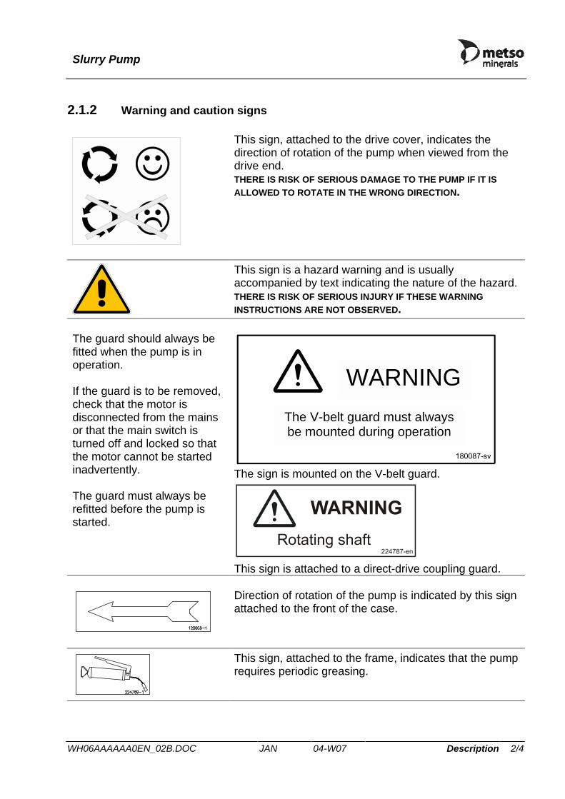
This sign, attached to the drive cover, indicates the direction of rotation of the pump when viewed from the drive end. THERE IS RISK OF SERIOUS DAMAGE TO THE PUMP IF IT IS ALLOWED TO ROTATE IN THE WRONG DIRECTION.
This sign is a hazard warning and is usually accompanied by text indicating the nature of the hazard. THERE IS RISK OF SERIOUS INJURY IF THESE WARNING INSTRUCTIONS ARE NOT OBSERVED.
The V-belt guard must alwaysbe mounted during operation
WARNING
The sign is mounted on the V-belt guard.
The guard should always be fitted when the pump is in operation. If the guard is to be removed, check that the motor is disconnected from the mains or that the main switch is turned off and locked so that the motor cannot be started inadvertently. The guard must always be refitted before the pump is started.
This sign is attached to a direct-drive coupling guard.
Direction of rotation of the pump is indicated by this sign attached to the front of the case.
This sign, attached to the frame, indicates that the pump requires periodic greasing.
Slurry Pump
WH06AAAAAA0EN_02B.DOC JAN 04-W07 Description 3/4
2.2 Applications The Metso Minerals Slurry Pump has been designed for a wide variety of abrasive pumping duties. While the pumps may be used in many different industries, they are all designed for constant use in the most arduous conditions. These high-efficiency pumps are of a simple design, providing ease of maintenance and facilitating replacement of wearing parts.
2.3 Design
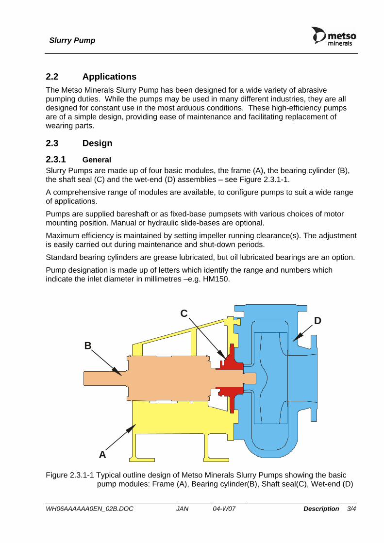
2.3.1 General Slurry Pumps are made up of four basic modules, the frame (A), the bearing cylinder (B), the shaft seal (C) and the wet-end (D) assemblies – see Figure 2.3.1-1. A comprehensive range of modules are available, to configure pumps to suit a wide range of applications. Pumps are supplied bareshaft or as fixed-base pumpsets with various choices of motor mounting position. Manual or hydraulic slide-bases are optional. Maximum efficiency is maintained by setting impeller running clearance(s). The adjustment is easily carried out during maintenance and shut-down periods. Standard bearing cylinders are grease lubricated, but oil lubricated bearings are an option. Pump designation is made up of letters which identify the range and numbers which indicate the inlet diameter in millimetres –e.g. HM150.
A
B
CD
Figure 2.3.1-1 Typical outline design of Metso Minerals Slurry Pumps showing the basic
pump modules: Frame (A), Bearing cylinder(B), Shaft seal(C), Wet-end (D)

Slurry Pump
WH06AAAAAA0EN_02B.DOC JAN 04-W07 Description 4/4
2.3.2 Noise level In certain installations and outside the optimum operating conditions, the noise level of 70 dB(A) may be exceeded. The motor generates most of the noise and, in general, the noise level for properly designed installations will be about 2dB(A) above that of the motor.
2.3.3 Vibration The pumps are in ClassIV as described in ISO10816-1. When the pump is new, the vibration level at any bearing should not exceed 7.1 mm/s. Vibration levels above 11 mm/s should always receive attention.
CAUTION SHOULD VIBRATION LEVELS EXCEED 18 mm/s, STOP THE PUMP IMMEDIATELY.
Common reasons for high vibrations are:
⇒ inadequately tightened fasteners; ⇒ slack V-belt; ⇒ misalignment of the drive; ⇒ the pump impeller is blocked by debris.

Slurry Pump
WH07HM1AAA0en_05c.doc JAN 04-W08 Description 1/1
2.4 Materials and maximum working pressures Metso Minerals Slurry Pumps are constructed from materials selected to give excellent wear characteristics over the full range of pumping duties. This section lists the materials of construction and working pressures for STANDARD duty applications. Other materials are also used for specialist applications or as specified by the customer – see section 1.3 .
MATERIALS OF CONSTRUCTIONItem Material Type Material Code Material Standard Case White Cast Iron JN3049 EN 12513 Impeller White Cast Iron JN3049 EN 12513
Back Liner White Cast Iron JN3049 EN 12513
Bearing Frame Cast Iron JS1030 EN 1563
Expeller White Cast Iron JN3049 EN 12513
Expeller Ring White Cast Iron JN3049 EN 12513
Expeller Ring (option) Cast Iron JS1030 PU Lined EN 1563
Stuffing Box Cast Iron JS1030 EN 1563
Shaft Sleeve White Cast Iron JN3049 EN 12513
Shaft Sleeve (option) Stainless Steel 1.4401 EN 10088
Shaft Sleeve (option) Stainless Steel 1.4021 EN 10088
Shaft Sleeve (option) Stainless Steel 1.4462 EN 10088
Shaft Steel 1.1191 EN 10083
Seals Nitrile Rubber NBR -
PUMP WORKING PRESSURES
SIZE Bar kPa HM50 18.6 1860
HM75 18.6 1860
HM100 15.9 1590
HM150 15.6 1560
HM200 15.6 1560
HM250 15.6 1560
HM300 15.6 1560

Slurry Pump
WH08AAAAAA0EN_06B.DOC JAN 04-W24 Description 1/1
2.5 Surface treatment
2.5.1 Standard finish The external surfaces of the pump are protected by the anti-corrosive system specified in Table 2.5.1-1, except exposed machined surfaces which are coated with an air drying rust inhibitor. Drive motors are supplied in the original manufacturer’s standard finish. Stainless steel, plastic or elastomeric parts are not painted. Table 2.5.1-1 Paint specification
COATING TYPE COLOUR Finish 70 DFT (µm)Finish (all except guards)
Two-pack gloss oxiranester thick coat paint
Blue (RAL 5009)
Gloss 120
Finish (guards only)
Epoxy powder Yellow (RAL 1032)
Gloss 100
2.5.2 Paint repairs To repair damage to a painted surface;
1. remove any trace of oil and dirt using solvent wash; 2. remove all loose paint by chipping or scraping back until only sound paintwork
remains and clean the exposed surface by wire brushing or other mechanical means to grade St2 of Swedish Standard SS 055900 (ISO 8501-1:1988);
3. sand down and feather a 25mm band of the sound bordering paintwork; 4. vacuum the surface to remove all dust and debris; 5. apply the paint system specified in Table 2.5.1-1.


Pump HM100 C5 Performance curve
13AAAAHCHCC5 Edition 4 HWT 06-W22 Description 1/1
Full impeller dia
300 mm
Vane diameter
300 mm
Vane config
Full
Impeller type
Closed
No. of vanes
5
Max sphere
30 mm
Impeller material
Metal
Liner material
Metal
H (m)
50 100 150 200 250
20
40
60
80
100
800
1000
1200
1400
1600
1800
2000
2200
2400
2600 r/min
BEL
40% 50% 55%60%
65%
67%
65%
60%1,00 m
2,00 m
3,00 m
4,00 m
5,00 m
6,00 m
P (kW)
Q (m³/h)
50 100 150 200 250
20
40
60
80
Based on clear water testscorrect for other conditions
800 1000
1200 1400
1600
1800
2000
2200
2400
2600

Slurry Pump
100-conformity-en Edition 0 JAN 04-W16 Declaration of conformity 1/1
2.8 Certificates and test results
DECLARATION OF CONFORMITY
We, Metso Minerals (Sala) AB, Norrängsgatan 2, 733 25 SALA, SWEDEN declare that the slurry pump
Manufacturer Metso Minerals (Sala) AB Pump type HM100 MHC-D Pump number 26172301001 Year of manufacturing 2006
to which this declaration relates is in conformity with the following standards - EN 292-1 Safety of machinery – Basic terminology, methodology - EN 292-2 Safety of machinery – Technical principles and specifications - EN 809 Pumps and pump units for liquids - common safety
requirements - EN13463-1 Non-electrical equipment for potentially explosive atmospheres – Basic method and requirements - EN13463-5 Non-electrical equipment for potentially explosive atmospheres – Protection by constructional safety
following the provisions of Directive: 98/37/EG : 94/9/EC
2004-04-14 in Sala, Sweden
Name: Jan Andersson
Position: General manager Slurry pump division
CE marking
European Commission mark for EX-products
Equipment group: Surface
Equipment category Gas
Pump type
Pump number
Year of manufacture


CERTIFICATEDate 2006-01-11 Page 1/2No. A/06-535612 Rev 00
INSPECTION CERTIFICATE acc to Huhnseal AB EN 10 204 3.1 Box 288 261 23 LANDSKRONA Customer References Sandvik References Customer Order No. Subs No. ABSMT Dispatch note 640224 order 123034 58554 39152/53 2005-12-19 ABSMT No. C.Code 284-55835 87 003-00991 HUHNSEAL Material description Steel/material Designations HOT WORKED STAINLESS BAR STEEL Sandvik FORGED SANMAC 316/SANMAC 316L ANNEALED & STRAIGHTENED AISI UNS PEEL TURNED AND POLISHED 316/316L S31600/S31603 W.nr EN no 1.4401/1.4404 1.4401/1.4404 Steel making process Electric furnace Technical requirements EN 10088-3:-2005 NACE MR0175/ISO 15156-3:2003 ASTM A-276-04, A-479-04, ASME SA-479-ED-04 SEC II PART A EXTENT OF DELIVERY It Product designation Heat Lot Pieces Kg 02 MBR-SANMAC-316L-240 507843 11241 15 120.0 FL-15-22- Total 15 120.0 TEST RESULTS Chemical composition (weight%) Heat C Si Mn P S Cr Ni Mo 507843 0.013 0.24 1.67 0.026 0.026 16.73 10.18 2.05 V N 507843 0.033 0.045 Tensile test at room temperature Yield strength Tensile strength Elongation Red.of Area N/mm2 N/mm2 N/mm2 % % % Lot Rp0.2 Rp1.0 Rm A 2" Z 11241 244 287 521 60 60 68 Hardness test Min Max Lot HB HB 11241 152.0 153.0 Quality assurance - Ulf Svensson/QA-manager Primary Products MTC Service / Certificates AB SANDVIK MATERIALS TECHNOLOGY Reg No. 556234-6832 VAT No. SE663000-060901 SE-81181 SANDVIKEN SWEDEN www.smt.sandvik.com [email protected]
CERTIFICATEDate 2006-01-11 Page 2/2No. A/06-535612 Rev 00
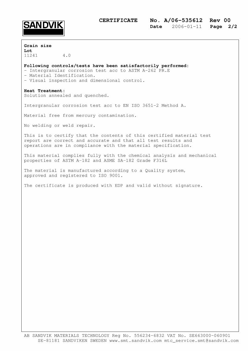
Grain size Lot 11241 4.0 Following controls/tests have been satisfactorily performed: - Intergranular corrosion test acc to ASTM A-262 PR.E - Material Identification. - Visual inspection and dimensional control. Heat Treatment: Solution annealed and quenched. Intergranular corrosion test acc to EN ISO 3651-2 Method A. Material free from mercury contamination. No welding or weld repair. This is to certify that the contents of this certified material test report are correct and accurate and that all test results and operations are in compliance with the material specification. This material complies fully with the chemical analysis and mechanical properties of ASTM A-182 and ASME SA-182 Grade F316L The material is manufactured according to a Quality system, approved and registered to ISO 9001. The certificate is produced with EDP and valid without signature. AB SANDVIK MATERIALS TECHNOLOGY Reg No. 556234-6832 VAT No. SE663000-060901 SE-81181 SANDVIKEN SWEDEN www.smt.sandvik.com [email protected]

Certificate of compliance Certificate number 0508 Customer name Metso Minerals The certificate is issued to certify that the material we supply to Metso for components in the “Denver Orion range”, PD731047, PDCH2012, PD771010, PD741041, complies with the following specification : MIS NO MITAK
Closest Metso NO.
C
Si (max)
Mn
P (max)
S (max)
Cr
Ni (max)
Mo (max)
Cu (max)
Bhn (min)
1001
EN-JN3049
2.4 to 2.8
1% max
0.5 to 1.0
0.06 max
0.06max
23.0 to 27.0
1 % max
0.5 max
1 % max
600
For and on behalf of MIS Engineering (PTY) Ltd Goosen Dhladla Quality manager 13 Mars 2006


Slurry Pump
WH14AAAAAA0EN_04D.DOC JAN 04-W08 Health & safety 1/2
3 HEALTH AND SAFETY
3.1 General
HEALTH AND SAFETY STATEMENT DO TAKE TIME TO ENSURE THAT YOUR SAFETY AND THAT OF OTHERS IS NOT PUT AT RISK. FAILURE TO OBSERVE CERTAIN ELEMENTARY SAFETY PRECAUTIONS MAY RESULT IN PERSONAL INJURY OR DAMAGE TO THIS PUMP EQUIPMENT. THE SAFETY INFORMATION IN THIS AND OTHER SECTIONS IS INTENDED TO ENCOURAGE A SAFETY CONSCIOUS APPROACH TO OPERATING AND CARRYING OUT MAINTENANCE.
3.1.1 Warnings and cautions For the purpose of definition in this manual, a WARNING gives information which if ignored could lead to serious injury of personnel. A CAUTION gives infomation which if ignored could lead to serious damage to the pump or associated equipment.
WARNING PARAGRAPHS WHICH PURELY PROVIDE A WARNING NOTICE ARE BOXED AND HIGHLIGHTED IN THIS STYLE.
CAUTION PARAGRAPHS WHICH PURELY PROVIDE A CAUTIONARY NOTICE ARE BOXED AND HIGHLIGHTED IN THIS STYLE.
3.1.2 Training It is strongly recommended that all customers' production and maintenance personnel and site visitors are made fully aware of potential dangers of this equipment. If any doubt exists, please contact Metso Minerals for advice. FOR YOUR OWN PERSONAL SAFETY , READ AND TAKE NOTE OF THE FOLLOWING:
HAZARDOUS AREAS - These are in the areas of the impeller, shaft seal,
impeller release mechanism, drive motor shaft, direct drive coupling or drive belts. Under normal operating conditions these areas MUST be enclosed by safety covers or guards. Pump intake and discharge ports, when open, are also hazardous areas. NEVER insert your hand into either of these ports without first ensuring that the pump drive has been isolated.
Slurry Pump
WH14AAAAAA0EN_04D.DOC JAN 04-W08 Health & safety 2/2
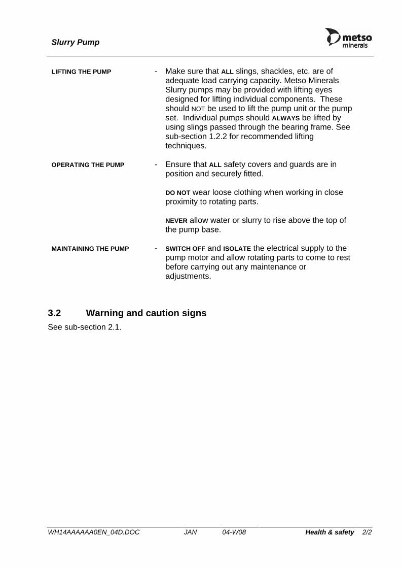
LIFTING THE PUMP - Make sure that ALL slings, shackles, etc. are of adequate load carrying capacity. Metso Minerals Slurry pumps may be provided with lifting eyes designed for lifting individual components. These should NOT be used to lift the pump unit or the pump set. Individual pumps should ALWAYS be lifted by using slings passed through the bearing frame. See sub-section 1.2.2 for recommended lifting techniques.
OPERATING THE PUMP - Ensure that ALL safety covers and guards are in position and securely fitted. DO NOT wear loose clothing when working in close proximity to rotating parts. NEVER allow water or slurry to rise above the top of the pump base.
MAINTAINING THE PUMP - SWITCH OFF and ISOLATE the electrical supply to the pump motor and allow rotating parts to come to rest before carrying out any maintenance or adjustments.
3.2 Warning and caution signs See sub-section 2.1.
Slurry Pump
WH14AAAAAA0EN_04D.DOC JAN 04-W08 Desccription of operation 1/4
4 DESCRIPTION OF OPERATION
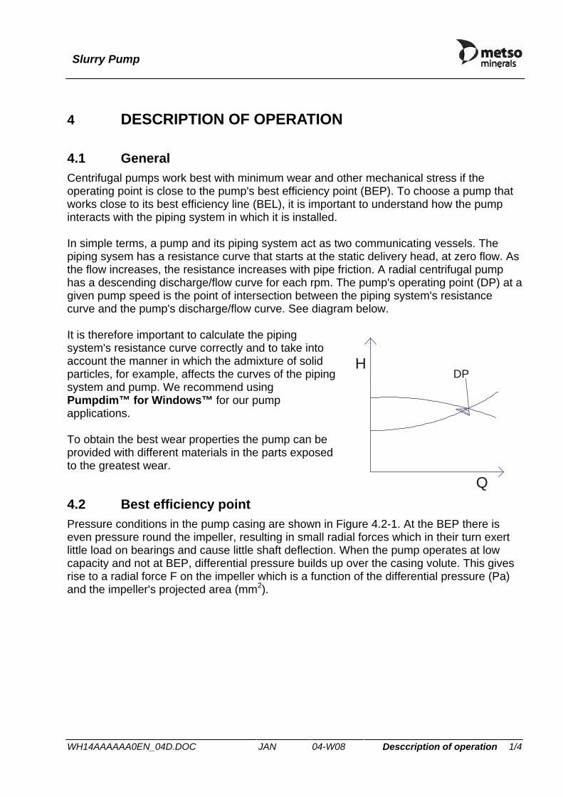
4.1 General Centrifugal pumps work best with minimum wear and other mechanical stress if the operating point is close to the pump's best efficiency point (BEP). To choose a pump that works close to its best efficiency line (BEL), it is important to understand how the pump interacts with the piping system in which it is installed. In simple terms, a pump and its piping system act as two communicating vessels. The piping sysem has a resistance curve that starts at the static delivery head, at zero flow. As the flow increases, the resistance increases with pipe friction. A radial centrifugal pump has a descending discharge/flow curve for each rpm. The pump's operating point (DP) at a given pump speed is the point of intersection between the piping system's resistance curve and the pump's discharge/flow curve. See diagram below. It is therefore important to calculate the piping system's resistance curve correctly and to take into account the manner in which the admixture of solid particles, for example, affects the curves of the piping system and pump. We recommend using Pumpdim™ for Windows™ for our pump applications. To obtain the best wear properties the pump can be provided with different materials in the parts exposed to the greatest wear.
4.2 Best efficiency point Pressure conditions in the pump casing are shown in Figure 4.2-1. At the BEP there is even pressure round the impeller, resulting in small radial forces which in their turn exert little load on bearings and cause little shaft deflection. When the pump operates at low capacity and not at BEP, differential pressure builds up over the casing volute. This gives rise to a radial force F on the impeller which is a function of the differential pressure (Pa) and the impeller's projected area (mm2).
Q
HDP
Slurry Pump
WH14AAAAAA0EN_04D.DOC JAN 04-W08 Desccription of operation 2/4
Q
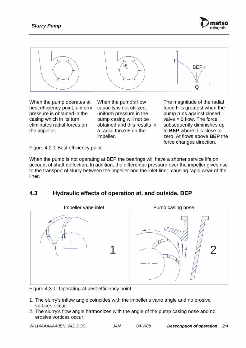
FF
BEP
When the pump operates at best efficiency point, uniform pressure is obtained in the casing which in its turn eliminates radial forces on the impeller.
When the pump's flow capacity is not utilized, uniform pressure in the pump casing will not be obtained and this results in a radial force F on the impeller.
The magnitude of the radial force F is greatest when the pump runs against closed valve = 0 flow. The force subsequently diminishes up to BEP where it is close to zero. At flows above BEP the force changes direction.
Figure 4.2-1 Best efficiency point When the pump is not operating at BEP the bearings will have a shorter service life on account of shaft deflection. In addition, the differential pressure over the impeller gives rise to the transport of slurry between the impeller and the inlet liner, causing rapid wear of the liner.
4.3 Hydraulic effects of operation at, and outside, BEP
Impeller vane inlet Pump casing nose
1 2
Figure 4.3-1 Operating at best efficiency point 1. The slurry's inflow angle coincides with the impeller's vane angle and no erosive
vortices occur. 2. The slurry's flow angle harmonizes with the angle of the pump casing nose and no
erosive vortices occur.

Slurry Pump
WH14AAAAAA0EN_04D.DOC JAN 04-W08 Desccription of operation 3/4
The way in which the hydraulic work is affected when the pump does not operate at BEP is shown in Figure 4.3-2 and Figure 4.3-3 This is of decisive importance in slurry pumping.
Impeller vane inlet Pump casing nose
43 5
6
Figure 4.3-2 Operating outside BEP - At low load 3. Abrasion on the impeller vane's discharge side. 4. Vortices occur on the vane's vacuum side. 5. Vortices. 6. Abrasion caused by particles striking and bouncing against the surface.
Impeller vane inlet Pump casing nose
78
9
10
Figure 4.3-3 Operating outside BEP - On overloading 7. Vortices are formed on the discharge side of the impeller vane. 8. Abrasion occurs on the vacuum side of the vane tip. 9. Vortices. 10. Abrasion on the pump casing nose.

Slurry Pump
WH14AAAAAA0EN_04D.DOC JAN 04-W08 Desccription of operation 4/4
Hydraulic efficiency is a function of hydraulic turbulence - the more turbulence, the less efficiency. In slurry pumping, a high level of efficiency is therefore important. Little hydraulic turbulence is formed at BEP and the abrasion is chiefly of a sliding nature, since the differential pressure is low when the slurry passes through the impeller and pump casing. The rate of abrasion is low and the wear is spread evenly over the surfaces. The rasping wear or high-pressure wear that occurs between the impeller and suction side liner is lower, since the evenly distributed hydraulic pressure reduces recirculation. When the full capacity of the pump is not used and its efficiency is less than at BEP, hydraulic turbulence occurs and the solid particles in the slurry strike and rasp the impeller and pump casing. This causes local wear damage and the service life of these components is severely shortened. At the inlet to the impeller the slurry's flow angle is not the same as the pump vane angle, which gives rise to turbulence and results in recirculation of slurry in the channel. At the pump casing nose the flow from the impeller does not harmonize with the shape of the casing, causing turbulence to occur immediately after the pump casing nose. In the worst case, oversized pumps which do not operate at BEP result in bearing breakdown, shaft fracture and unevenly worn inlet and pump casing liners with deep wear marks at the casing nose.
4.4 Choice of pump size For preference, choose the pump size which operates as close as possible to the pump's best efficiency point (BEP).
Slurry Pump
WH14AAAAAA0EN_04D.DOC JAN 04-W08 Control system 1/1
5 CONTROL SYSTEM
(NOT APPLICABLE)

Slurry Pump
WH15AM1AAA0EN_07A.DOC JAN 05-W02 Installation 1/8
6 INSTALLATION
6.1 General Refer to sub-section 1.2 for handling instructions.
6.2 Foundation requirements Ideally, the pump and its drive should be mounted on a common bedplate which is fixed to a level foundation of adequate strength. All bedplates supplied by Metso Minerals incorporate holding-down bolt holes. It is recommended that the pump is installed in such a way that maintenance and adjustments can be carried out easily. It is essential that the pump is not subjected to flooding. A foundation must provide a rigid and durable support, while absorbing shock loads and vibrations to and from the machine. Many criteria influence its design, its construction materials and its preparation: vibration and loading characteristics, operating environment and effect of nearby machinery are some. Each installation is, therefore, a special case needing careful examination of its particular requirements. The following are general guidelines for preparing a foundation for Metso Slurry Pumps –refer to Figure 6.2-1 for details.
A1
ØD
A min
B min
Mv
Ed
C min
C min > 1.25 × B min
< 1240
Ed > (12×ØD)A2
A3 A4
Figure 6.2-1 Foundation and fixings, general arrangement

Slurry Pump
WH15AM1AAA0EN_07A.DOC JAN 05-W02 Installation 2/8
1. The foundation must be poured on a well prepared solid ground. 2. A mixture of good quality cement and coarse aggregate is suitable in most cases,
but, where applicable, the chemistry of the soil and the operating environment may impose additional requirements. Reinforcement bars may also be necessary depending on application.
3. The total foundation mass and its related support structures should be at least five times the total weight of the rotating assembly. The weight of the rotating assembly – excluding the rotating parts of the motor – is roughly ¼ of the weight of the bare shaft pump. See section 11.3 for the bareshaft assembly weight.
4. Foundation depth (Cmin) should be at least 125% of the anchor hole depth (Bmin). 5. For maximum strength, anchor fixings should be positioned more that 12 times the
anchor hole diameter (ØD) from the edge of the concrete slab (Ed). 6. The concrete slab should be level to within 12.5 mm in 3000 mm. 7. If the installation is in close vicinity of other moving machinery, then necessary
precautions should be taken to prevent cross-talk.
6.3 Installation tools and equipment Apart from suitable lifting equipment, a standard fitter's tool kit together with suitably-sized hexagon key wrenches and torque wrenches are normally sufficient to install the pump. See Toolkit, sub-section 10.6. Metso Minerals can supply all recommended fixtures and tools at additional cost.
Slurry Pump
WH15AM1AAA0EN_07A.DOC JAN 05-W02 Installation 3/8
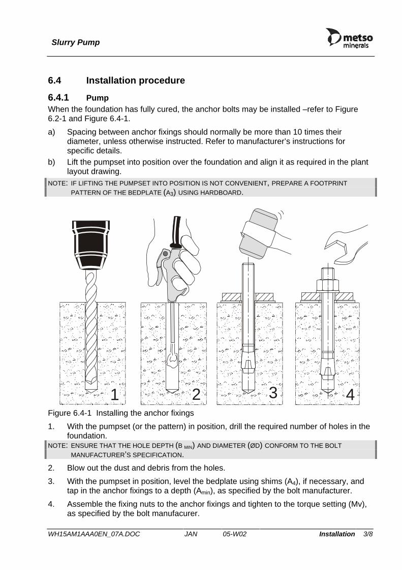
6.4 Installation procedure
6.4.1 Pump When the foundation has fully cured, the anchor bolts may be installed –refer to Figure 6.2-1 and Figure 6.4-1. a) Spacing between anchor fixings should normally be more than 10 times their
diameter, unless otherwise instructed. Refer to manufacturer’s instructions for specific details.
b) Lift the pumpset into position over the foundation and align it as required in the plant layout drawing.
NOTE: IF LIFTING THE PUMPSET INTO POSITION IS NOT CONVENIENT, PREPARE A FOOTPRINT PATTERN OF THE BEDPLATE (A3) USING HARDBOARD.
1 2 3 4
Figure 6.4-1 Installing the anchor fixings 1. With the pumpset (or the pattern) in position, drill the required number of holes in the
foundation. NOTE: ENSURE THAT THE HOLE DEPTH (B MIN) AND DIAMETER (ØD) CONFORM TO THE BOLT
MANUFACTURER’S SPECIFICATION. 2. Blow out the dust and debris from the holes. 3. With the pumpset in position, level the bedplate using shims (A4), if necessary, and
tap in the anchor fixings to a depth (Amin), as specified by the bolt manufacturer. 4. Assemble the fixing nuts to the anchor fixings and tighten to the torque setting (Mv),
as specified by the bolt manufacurer.

Slurry Pump
WH15AM1AAA0EN_07A.DOC JAN 05-W02 Installation 4/8
6.4.2 Belt driven pumps
1. Make allowances for possible pump shaft forward adjustment when positioning the drive pulley on the shaft.
2. Align the pump and motor pulleys correctly. Misalignment between pulleys could cause excessive belt wear, heat generation and noise.
6.4.3 Direct driven pumps Where practicable, fit a spacer coupling so that the pump "back pull-out" method can be used, thus avoiding the need to remove the drive or other equipment. The minimum distance between shaft ends needed to facilitate the "back pull-out" method is given in, ‘General Arrangement’, sub-section 2.6. NOTE: ALWAYS CHECK DRIVE ALIGNMENT AFTER INSTALLATION.
6.4.4 General installation procedure 1. Check that the inlet and outlet openings and the case are clear of any debris and that
the respective joint seals are in position before connecting the pipework. WARNING
WHERE THE SYSTEM IN WHICH THE PUMP IS INSTALLED IS DESIGNED IN SUCH A WAY THAT THE PUMP INLET AND OUTLET LINES CAN BE SHUT OFF OR COULD BECOME BLOCKED SIMULTANEOUSLY, SET THE SAFETY VALVE TO THE PRESSURE SPECIFIED IN ‘MATERIALS AND MAXIMUM WORKING PRESSURES’, SECTION 2.4. THIS IS DESIGNED TO ELIMINATE THE RISK OF THE PUMP BURSTING, WHICH COULD HAPPEN IF THE PUMP IS RUNNING WITH BOTH THE INLET AND OUTLET LINES SHUT OFF.
2. DO NOT force the pipes into alignment with the inlet and outlet joint flanges. Avoid unnecessary loads on the pump by ensuring that all pipework is adequately supported and is not resting on the pump. See table 6.5.1
NOTE: THE JOINT FLANGES ARE SPLIT FOR EASE OF ASSEMBLY. IF FOUND TO BE LOOSE, TIGHTEN THE RESPECTIVE SCREWS TO THE TORQUE LOADING NOTED IN THE TORQUE TABLE, SUB-SECTION 11.1.
3. Disconnect the drive belts or coupling before connecting the electrical supply to the drive motor.
4. Run the motor and check that it turns in the direction indicated by the arrow sign –see section 2.1.2.
CAUTION THE PUMP MUST NOT BE RUN IN THE OPPOSITE DIRECTION AS THIS COULD RESULT IN THE IMPELLER UNWINDING FROM THE SHAFT, CAUSING EXTENSIVE DAMAGE TO THE PUMP.
5. Reconnect the drive belts or couplings as necessary. 6. Re-check drive component alignments, and re-set if necessary –see section 9.5.6 . NOTE: ALWAYS CHECK DRIVE ALIGNMENT AFTER INSTALLATION.

Slurry Pump
WH15AM1AAA0EN_07A.DOC JAN 05-W02 Installation 5/8
7. Connect the gland water supply pipe, in case of pumps with a water flush gland seal. Water must be clean, and at the correct pressure and flow rate. See Table 6.4.4-1 and section 9.5.3.
Recommended water quality for flushed gland pH : 6.5 to 8 Dissolved solids : < 1000 PPM Suspended solids : < 100 PPM Max particle size : - 60µ Max individual dissolved ions : Hardness (Ca+, Mg+) : < 10º dH Calcium Carbonate (CaCO3) : < 20 PPM Sulphate (SO4-) : < 50 PPM
Table 6.4.4-1 Recommended water quality for flush water
8. Ensure that all safety covers are fixed securely in position. NOTE: IF THE PUMP HAS BEEN BROUGHT OUT OF STORAGE, LUBRICANT RENEWAL MAY BE
ADVISABLE. SEE LONG TERM STORAGE RECOMMENDATIONS IN SECTION 1.2.4 .
6.4.5 Cold climates Where there is the likelihood of pump being exposed to below freezing conditions the following precautions are strongly recommended.
1. If practical, on site all pumps should be installed with their outlets in position-3 as shown in ‘General Arrangement’, sub-section 2.6.
2. Immediately pump is stopped drain discharge pipework. 3. Where practicable, fix adequate drain plugs on discharge pipework local to pump. 4. Disconnect flange fixings to pump oulet and inlet. Siphon out as much of the slurry
as possible.
A small amount of slurry can remain in bottom of pump case provided it does not come in contact with the impeller.
These precautions will make it possible to drain the pump and its pipework of all slurry during shut-downs.
6.4.6 Pump outlet positions To reposition the pump case outlet to suit existing pipework, follow relevant instructions in Dismantling and Assembly, section 9.5. ‘General Arrangement’, sub-section 2.6 shows the possible outlet positions.
Slurry Pump
WH15AM1AAA0EN_07A.DOC JAN 05-W02 Installation 6/8
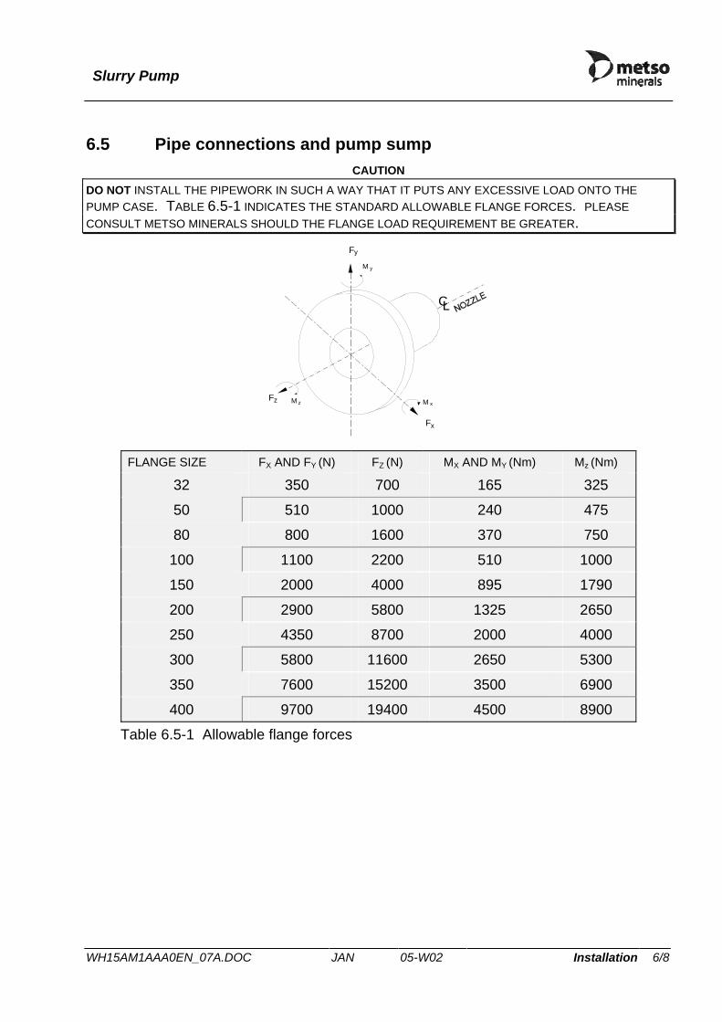
6.5 Pipe connections and pump sump CAUTION
DO NOT INSTALL THE PIPEWORK IN SUCH A WAY THAT IT PUTS ANY EXCESSIVE LOAD ONTO THE PUMP CASE. TABLE 6.5-1 INDICATES THE STANDARD ALLOWABLE FLANGE FORCES. PLEASE CONSULT METSO MINERALS SHOULD THE FLANGE LOAD REQUIREMENT BE GREATER.
CL
Fy
yM
Fx
M xz zMF
FLANGE SIZE FX AND FY (N) FZ (N) MX AND MY (Nm) Mz (Nm)
32 350 700 165 325
50 510 1000 240 475
80 800 1600 370 750
100 1100 2200 510 1000
150 2000 4000 895 1790
200 2900 5800 1325 2650
250 4350 8700 2000 4000
300 5800 11600 2650 5300
350 7600 15200 3500 6900
400 9700 19400 4500 8900
Table 6.5-1 Allowable flange forces
Slurry Pump
WH15AM1AAA0EN_07A.DOC JAN 05-W02 Installation 7/8
45º-60º
D
L
V(m )3
15s V/Q 2min< <Q(m /s)3
(4 × D) L (10 × D)< <
d
F
S
h
H
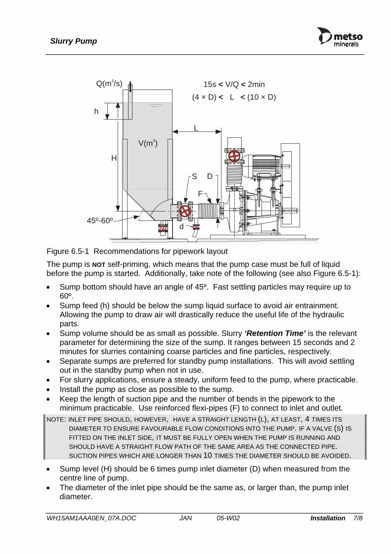
Figure 6.5-1 Recommendations for pipework layout The pump is NOT self-priming, which means that the pump case must be full of liquid before the pump is started. Additionally, take note of the following (see also Figure 6.5-1):
• Sump bottom should have an angle of 45º. Fast settling particles may require up to 60º.
• Sump feed (h) should be below the sump liquid surface to avoid air entrainment. Allowing the pump to draw air will drastically reduce the useful life of the hydraulic parts.
• Sump volume should be as small as possible. Slurry ‘Retention Time’ is the relevant parameter for determining the size of the sump. It ranges between 15 seconds and 2 minutes for slurries containing coarse particles and fine particles, respectively.
• Separate sumps are preferred for standby pump installations. This will avoid settling out in the standby pump when not in use.
• For slurry applications, ensure a steady, uniform feed to the pump, where practicable. • Install the pump as close as possible to the sump. • Keep the length of suction pipe and the number of bends in the pipework to the
minimum practicable. Use reinforced flexi-pipes (F) to connect to inlet and outlet. NOTE: INLET PIPE SHOULD, HOWEVER, HAVE A STRAIGHT LENGTH (L), AT LEAST, 4 TIMES ITS
DIAMETER TO ENSURE FAVOURABLE FLOW CONDITIONS INTO THE PUMP. IF A VALVE (S) IS FITTED ON THE INLET SIDE, IT MUST BE FULLY OPEN WHEN THE PUMP IS RUNNING AND SHOULD HAVE A STRAIGHT FLOW PATH OF THE SAME AREA AS THE CONNECTED PIPE. SUCTION PIPES WHICH ARE LONGER THAN 10 TIMES THE DIAMETER SHOULD BE AVOIDED.
• Sump level (H) should be 6 times pump inlet diameter (D) when measured from the centre line of pump.
• The diameter of the inlet pipe should be the same as, or larger than, the pump inlet diameter.

Slurry Pump
WH15AM1AAA0EN_07A.DOC JAN 05-W02 Installation 8/8
• A drain valve should be incorporated in the inlet pipe. A floor channel should also be provided directly beneath it for recovering the waste slurry.
• Secure the pump inlet and outlet pipes separately to avoid unnecessary transmission of vibrations, forces or moments to the pump.
• Use expansion joints for high-pressure applications.
6.6 Shaft gland See Care and Maintenance, Section 9, for specific installation instructions.
6.7 Motor and drive See Care and Maintenance, Section 9, for specific installation instructions.

Slurry Pump
WH15AM1AAA0EN_07A.DOC JAN 04-W51 Commissioning 1/1
7 COMMISSIONING
WARNING BEFORE CARRYING OUT THE FOLLOWING CHECKS, ISOLATE THE ELECTRICAL SUPPLY TO THE MOTOR.
1. If the pipework has not been connected to the pump on installation, ensure that the pump case and associated pipework are clear of any construction debris, slurry etc. before connection.
2. Ensure that the foundation and the securing bolts are tight. 3. Check that the rotating assembly is free to turn manually. 4. Check that the direction of rotation is correct -see General installation procedure,
section 6.4.4. CAUTION
THE PUMP MUST NOT BE RUN IN THE OPPOSITE DIRECTION AS THIS COULD RESULT IN THE IMPELLER UNWINDING FROM THE SHAFT, CAUSING EXTENSIVE DAMAGE TO THE PUMP.
5. Check lubrication. NOTE: THE BEARINGS AND SEAL ASSEMBLIES ARE GREASE PACKED ON ASSEMBLY. SEE
LUBRICATION, SUB-SECTION 9.4.
6. Ensure that the openings on each side of the bearing frame and the area around the gland are clear of debris, dried slurry, etc.
7. Check that all safety guards are secured in position.

Slurry Pump
WH15AM1AAA0EN_07A.DOC JAN 05-W02 Operation 1/2
8 OPERATING INSTRUCTIONS
8.1 Start-up
1. If the pump has just been maintained or has not been put into operation for some time, then carry out the pre-start checks as described in Commissioning, section 7.
2. Open the pump inlet and outlet valves. 3. Check for leakage from the inlet and outlet connections. NOTE: AN INLET-SIDE LEAK MAY CAUSE THE PUMP TO DRAW AIR DURING OPERATION, THUS
DRASTICALLY REDUCING ITS PUMPING CAPACITY.
4. If a water flushed gland is fitted, ensure that the water supply is turned on, and water is available at the correct pressure and flow rate.
5. If a mechanical seal is fitted, see section 9.5.3 before start up. 6. If auxiliary priming equipment is fitted, start the priming pump. 7. Start the pump drive motor.
8.2 Shutting down The appropriate shutdown procedure for any installation depends on the slurry being pumped, and more generally on the process requirements upstream and downstream of the pump. What follows, therefore, may only be regarded as general guidelines for ensuring some degree of protection for the pump without reference to the particular application.
• Where practicable, switch the pump to clean water and allow the pipeline to be flushed through before shutting down.
• In case of systems with substantial discharge pipework and/or head of slurry, means of isolating the pump or draining the system should be provided –see section 6.5.
CAUTION STOPPING THE PUMP WHEN THERE IS A HEAD OF SLURRY IN THE DISCHARGE PIPE SHOULD BE AVOIDED AS THIS COULD RESULT IN DAMAGE TO THE GLAND AND/OR PUMP.
• Having shut down the pump on clean water, close its isolating valves and then drain the pump and its pipework, if required.
CAUTION ALWAYS CLOSE THE OUTLET VALVE FIRST. NEVER CLOSE THE INLET VALVE WHILE THE PUMP IS RUNNING.
NOTE: REVERSE FLOW, IN ADDITION TO POSING A RISK OF DAMAGE TO THE SHAFT SEAL, CAN ALSO CAUSE THE IMPELLER TO SPIN IN THE REVERSE DIRECTION. STARTING THE PUMP UNDER THESE CONDITIONS MIGHT CAUSE DAMAGE TO A MECHANICAL SEAL, IF FITTED, AND/OR CAN IN EXTREME CASES CAUSE THE SHAFT TO SHEAR. AN OVERRIDE CIRCUIT IS RECOMMENDED TO PREVENT THE PUMP BEING STARTED INADVERTENTLY WHILE THE IMPELLER IS ROTATING.

Slurry Pump
WH15AM1AAA0EN_07A.DOC JAN 05-W02 Operation 2/2
• For short stoppage periods ONLY and where there is NO risk of the slurry settling out, or solidifying in the system:
Pumps with expeller seal - immediately after shutting down, close the
isolation valves and then drain the pump and the sump, if necessary.
Pumps with water flushed gland or mechanical seal
leave the flush water ‘ON’ when shutting down the pump, then close the isolation valves and finally drain the pump and the sump, if necessary.
Where there is a risk of slurry settling out, or solidifying, refer to the plant operation manual for the appropriate shutdown procedure.
CAUTIONS FORMATION OF ICE CAN BLOCK OR BURST THE PIPEWORK AND THE PUMP CASE. IN BELOW FREEZING CONDITIONS, ENSURE THAT THE PUMP CASE, AND PUMP INLET AND OUTLET PIPEWORK IS DRAINED OF ALL SLURRY FOR ANY LENGTHY SHUT-DOWN.
8.3 Running checks During pump operation, the following checks should be made:
1. Check for leakage from the inlet and outlet connections, and from the gland seal. NOTE: AN UNTIGHT INLET FLANGE MAY NOT BE EASILY NOTICEABLE DURING OPERATION, AS THE
PUMP COULD BE DRAWING AIR. CHECK FOR INLET-SIDE LEAKS BEFORE START-UP.
2. Check for excessive noise and vibration -see Description, section 2. 3. Check bearing temperature and lubrication –see Lubrication, sub-section 9.4. 4. Periodically verify that the shaft seal is correctly adjusted. If a water flush gland seal
is fitted, ensure that the water supply is at the correct pressure and flow rate. (Refer to section 9.5.3 for shaft seal setting details.)
5. Check that the pump performance is satisfactory. (See Capacity Curves, section 2.7) NOTE: IF THE RUNNING CHECKS ARE UNSATISFACTORY, PUMP ADJUSTMENT OR MAINTENANCE MAY
BE REQUIRED.
IMPORTANT NOTE: AFTER THE FIRST 100 HOURS OF OPERATION, CHECK AND ADJUST THE IMPELLER AXIAL CLEARANCE. SEE SECTION 9.5.1.

Slurry Pump
WH16AM1TAA0EN_02A.DOC JAN 04-W51 Care and maintenance 1/6
9 CARE AND MAINTENANCE
9.1 Safety measures WARNINGS
ISOLATE THE PUMP FROM ALL SOURCES OF ELECTRICITY AND POWER, BEFORE COMMENCING ANY MAINTENANCE WORK.
ALWAYS ASCERTAIN THE NATURE OF THE PROCESS LIQUID BEFORE COMMENCING WORK ON A PUMP AND FOLLOW THE HEALTH AND SAFETY PROCEDURES RELEVANT TO THE PROCESS LIQUID. IT MAY BE HARMFUL TO HEALTH.
Should the process liquid be of a harmful or hazardous nature take the following precautions as a minimum; 1. always use protective goggles and rubber gloves; 2. flush the pump thoroughly with clean water, before opening the pump; 3. after removing the components, flush them thoroughly with clean water. 4. follow the health and safety instructions provided in section 3.
9.2 Preventive maintenance & service schedule
9.2.1 Routine maintenance Use the maintenance schedule below as a basis from which to produce a schedule suitable to each pumping application after experience in operation has been gained.
WARNING BEFORE CARRYING OUT ANY MAINTENANCE ENSURE THAT ALL ELECTRICAL SUPPLIES TO THE MOTOR AND ASSOCIATED EQUIPMENT ARE SWITCHED OFF AND ISOLATED. LOCK IN THE OFF POSITION OR ATTACH SUITABLE WARNING PLATES TO THE RELEVANT SWITCHES.
ITEM ACTION RUNNING HOURS
10 100 250 1000
Pump Case, Bearing Cylinder Housing and Gland Area Pipework
Keep all areas clean and free from debris, slurry etc.
×
Hydraulic cylinders (where applicable)
Check for oil leaks. Rectify, as required.
×
Inlet/Outlet Connections Check for security and leaks. Rectify as required.
×
Gland Seal - General Check for leaks. Tighten gland follower screws or renew seal as necessary.
×

Slurry Pump
WH16AM1TAA0EN_02A.DOC JAN 04-W51 Care and maintenance 2/6
ITEM ACTION RUNNING HOURS 10 100 250 1000
Water flushing gland seal. Check stuffing box connection for leaks. Rectify as necessary.
×
Centrifugal Gland Seal Tighten gland follower screws or renew seal as necessary.
×
Bearing Cylinder
Lubricate bearings. See section 9.4.
×
Check Bearings for overheating. × All fixings
Ensure attachments are secure. Tighten to correct torque as necessary.
×
Adjusting Screw Locknut (P38) See Torque Table, Section 11.1. × Inspect Drive Belts, if fitted, for
deterioration and damage. Replace as necessary. Check drive belt tension and adjust as necessary.
×
Check drive couplings, if fitted, for security of connection.
×
Pump/Drive unit installation Check safety covers for security of attachment - important ×
Check drive motor holding down bolts for security of attachment.
×
Keep drive motor clean and free from debris, slurry etc.
×
Service Drive Motor as necessary.
In accordance with manufacturer’s instructions.
Pump impeller Check axial clearance after run-in period. Adjust clearance by shimming. Refer to Setting Pump Clearances, sub-section 9.5.1.
After first 100 running hours and repeat at intervals equal to 25% of the anticipated life of the pump.
Slurry Pump
WH16AM1TAA0EN_02A.DOC JAN 04-W51 Care and maintenance 3/6
9.2.2 Maintenance recommendations Metso Minerals recommends that the following actions are carried out prior to any maintenance: • clean down the pump, removing any accumulation of debris and/or slurry; • ensure that inlet and outlet pipeline valves, if fitted, are closed;
WARNING BEFORE OPENING UP THE PUMP, MAKE SURE THAT ANY LIQUID PRESSURE HAS BEEN RELEASED.
• on breaking a joint face, keep the gasket and ensure it is replaced on assembly; • if using lifting gear to remove components, ensure that it is of adequate capacity and
that test certificates are valid; • on larger size pumps it is recommended that special tools are used to help assembly or
maintenance. For information regarding special tools please refer to Special Tools, section 9.3.

Slurry Pump
WH16AM1TAA0EN_02A.DOC JAN 04-W51 Care and maintenance 4/6
9.3 Tools and special equipment for service and maintenance NOTE: THE FOLLOWING SPECIAL TOOLS ARE AVAILABLE FOR PUMPS WITH EITHER SINGLE, OR
DOUBLE, ADJUSTMENT FRAMES. 1. A special crank-handle to fit over the drive-shaft end diameter and locate the drive
key is advantageous when fitting the impeller to the shaft. See Dismantling and Fitting the Hydraulic Parts, section 9.5.2.
Figure 9.3-1 Special crank handle

Slurry Pump
WH16AM1TAA0EN_02A.DOC JAN 04-W51 Care and maintenance 5/6
2. Two proprietary packing extractors to facilitate the removal of the packing will also be advantageous.
Figure 9.3-2 Packing extractor 3. Back-liners for large pumps are very heavy. Specially designed back-liner lifting tools
allow safe handling of the components.
Figure 9.3-3 Back-liner lifting tool for metal pumps

Slurry Pump
WH16AM1TAA0EN_02A.DOC JAN 04-W51 Care and maintenance 6/6
4. Shaft seals for large pumps are also quite heavy. A special shaft extension (E) facilitates removal and refitting of the seal assembly. The tool is also useful for removing the bearing assembly.
E
Figure 9.3-4 Shaft extension tool 5. A soft sling (strop) of appropriate lifting capacity (See Approximate Weights Table,
section 11.3) to lift the case assembly is required. CAUTION
TO PREVENT DAMAGE, ONLY USE A SOFT SLING (STROP) TO LIFT THE CASE.
All of the above special tools can be obtained from Metso Minerals. See section 10.6.

Slurry Pump
WH16AA1LA00EN_01E.DOC JAN 04-W08 Care and maintenance 1/3
9.4 Lubrication
9.4.1 First-fill and re-packing after major servicing Metso Minerals Slurry pumps are lubricated with SKF LGMT3 before dispatch. When renewing or re-fitting the bearings, they must again be re-packed with grease of the same specification as detailed in Table 9.4.1-1. The required quantity for each bearing is specified in Table 9.4.1-2.
Characteristic Specification Thickening agent : Lithium soap
Base oil viscosity at 40 °C : 120 cST
Base oil type : Mineral oil
Consistency NLGI : 3
Table 9.4.1-1 Grease specification
Frame size Grease quantity (g) FR250 75 FR300 100 FR400 125 FR500 325 FR600 500 FR750 625
Table 9.4.1-2 Bearing lubrication - First fill & re-packing

Slurry Pump
WH16AA1LA00EN_01E.DOC JAN 04-W08 Care and maintenance 2/3
9.4.2 Lubrication interval The bearings may be re-greased with any lithium-based grease that conforms to the specification detailed in Table 9.4.1-1. The lubrication interval depends upon the shaft speed and the bearing operating temperature, as shown in Table 9.4.2-1. Frame Grease Pump speed (rpm) Size (g) 500 800 1000 1500 2000 2500 3000
FR250 20 2275 1500 1000 650 500 350 250 FR300 25 1600 1300 900 600 400 300 200 FR400 35 1250 1000 750 500 350 - - FR500 50 1250 900 550 350 - - - FR600 70 1250 800 350 200 - - - FR750 90 900 550 200 - - - -
Table 9.4.2-1 Recommended lubrication interval for bearings @ 70°C (hours) The pump should initially be re-greased after 250 running hours or the recommended interval (whichever is less), unless stored for longer than 12 months before start-up, in which case the long-term storage instructions should be followed (See section 1.2).
Multiply above lubrication intervals by the factors given below if the normal bearing operating temperature (measured on the rim of the bearing end cover) differs from 70 °C.
Temperature (°C) 50 60 70 80 90 100 110 120 Multiplier 2.5 1.6 1.0 0.65 0.40 0.25 0.15 0.10
While the bearings and specified grease have a maximum operating temperature of 120°C, it is recommended that temperatures above 100 °C be avoided. However, transient temperatures between 100 °C and 120 °C are acceptable immediately following re-greasing.

Slurry Pump
WH16AA1LA00EN_01E.DOC JAN 04-W08 Care and maintenance 3/3
9.4.3 Lubrication points The pumps have two bearing lubrication points. See Figure 9.4.3-1. Part Position Qty.(cc) Frequency Lubricant Bearing cylinder
A See Table 9.4.2-1.
See Table 9.4.2-1.
SKF LGMT3 or equivalent - see Table 9.4.1-1.
Motor and/or gearbox (where applicable)
– – – See manufacturer’s instruction manual.
A
Figure 9.4.3-1 Lubrication point diagram- Bearing greasing points (A)

Slurry Pump
WH17AM1AAA0EN_04B.DOC JAN 04-W08 Care and maintenance 1/2
9.5 Dismantling and assembly
9.5.1 Setting pump clearances
• Impeller clearance adjustment (Standard Slurry Impeller) These adjustments enable the back (frame side) and front (inlet side) running clearances to be kept to a minimum so that maximum operating efficiency is maintained throughout the wear life of the pump. The back impeller clearance is adjusted using the adjusting screw and the front clearance by adding or removing case shims. When no further adjustment is possible, the pump must be disassembled and inspected and worn parts renewed. 1. Isolate the drive motor and attach suitable warning plates to the relevant switches. It
is advisable to remove the fuses and/or lock the isolator open to avoid accidental starting.
2. Remove the drive safety guard and disconnect the belt drive or direct coupling as applicable.
3. Where fitted, a mechanical seal requires setting for disassembly. Section 9.5.3 would provide the relevant instructions, where applicable.
4. Back (Frame Side) Clearance This clearance, which should be adjusted first, is achieved by moving the complete rotating assembly towards the drive end:
a) Pull off cover (P24) from the bearing frame and slacken housing clamp screws (P16) - 2 off, tension screws (P23) - 2 off, and adjusting screw locknut (P38).
b) While rotating shaft (B11) by hand, take up the back clearance by turning adjustment screw (P19) against retaining plate (P22) until impeller (W3) is just touching back liner (W4).
c) Back off the adjusting screw through the saddle until the end of the screw touches bearing frame (P14).
d) Rotate the adjusting screw one turn. Check that impeller (W3) clears back liner (W4).
e) Tighten tension screws (P23), housing clamp screws (P16) and adjusting screw locknut (P38).
NOTE:TENSION AND CLAMP SCREWS MUST BE TORQUE TIGHTENED TO THE TORQUE VALUES LISTED IN TORQUE SETTING TABLES, SECTION 11.1.
Having completed the back clearance, the front clearance should be adjusted as follows: 5. Front (Inlet Side) Clearance
NOTE:THE COMPLETE BEARING FRAME AND ROTATING ASSEMBLIES ARE MOVED TOWARDS THE CASE WHEN SETTING THIS CLEARANCE.
a) Slacken bearing frame screws (P11) and nuts (P1) on case bolts (P4). b) Insert a jack screw (P10) in each side of the frame flange and turn the screws
evenly to withdraw the bearing frame by approximately 4mm.

Slurry Pump
WH17AM1AAA0EN_04B.DOC JAN 04-W08 Care and maintenance 2/2
c) Unscrew the jack screws completely. d) Remove the case shim sets (P3). e) Reduce the gap between the bearing frame flanges and base/case support
(P13) by evenly tightening two diametrically opposite case nuts (P1) and bolts (P4) until impeller (W3) touches case (W1).
f) Measure the gap between the bearing frame and the base/case support . Assemble case shims to a thickness just greater than the gap measured.
g) Slacken off the two case bolts. Retract the bearing frame slightly and fit the shims.
h) Tighten case nuts (P1) and bolts (P4) evenly to the required torque loading. Check that the impeller rotates freely. Add shims as necessary if the impeller fouls the case after tightening.
NOTE: IMPELLER SHOULD BE AS CLOSE TO THE CASE AS POSSIBLE WITHOUT FOULING IT.
i) Tighten bearing frame screws (P11) to the required torque. 6. If fitted, reset the mechanical seal. 7. Re-connect the drive belt or half coupling as applicable making sure that the drive is
aligned correctly. Adjust as necessary to obtain the correct alignment. 8. Fit all safety guards.
Slurry Pump
WH18AA11D00EN_01G.DOC JAN 04-W08 Care and maintenance 1/4
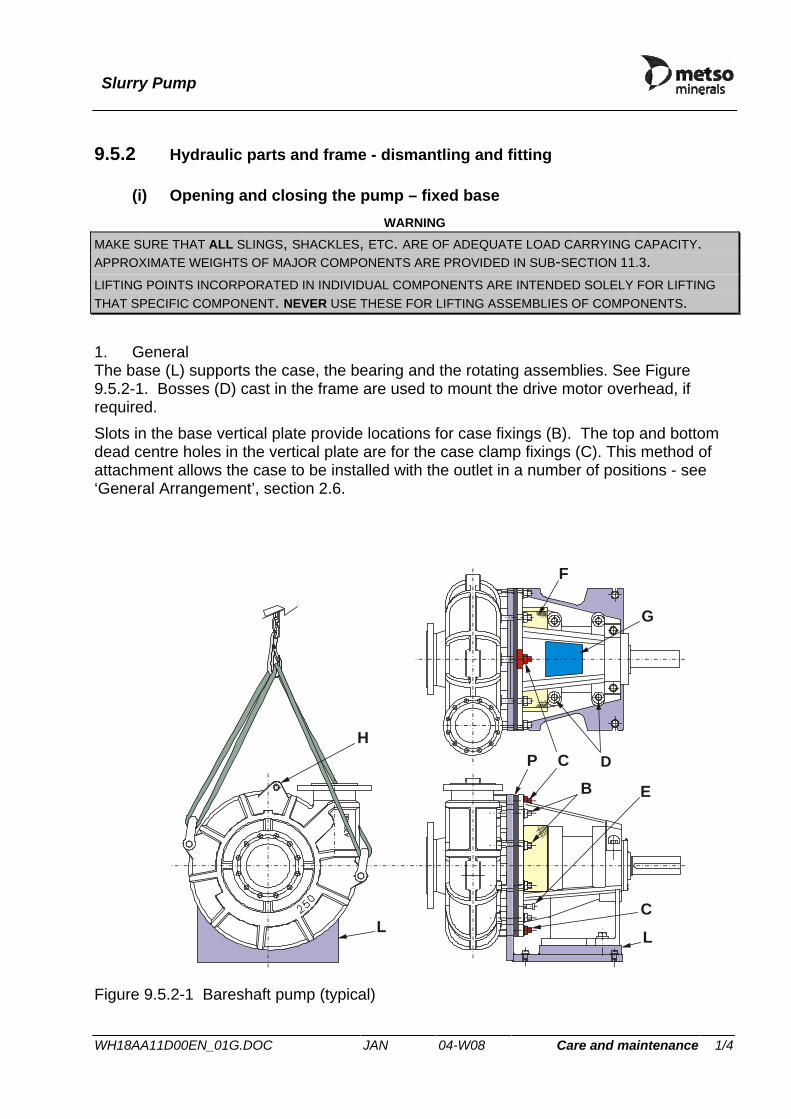
9.5.2 Hydraulic parts and frame - dismantling and fitting
(i) Opening and closing the pump – fixed base WARNING
MAKE SURE THAT ALL SLINGS, SHACKLES, ETC. ARE OF ADEQUATE LOAD CARRYING CAPACITY. APPROXIMATE WEIGHTS OF MAJOR COMPONENTS ARE PROVIDED IN SUB-SECTION 11.3. LIFTING POINTS INCORPORATED IN INDIVIDUAL COMPONENTS ARE INTENDED SOLELY FOR LIFTING THAT SPECIFIC COMPONENT. NEVER USE THESE FOR LIFTING ASSEMBLIES OF COMPONENTS.
1. General The base (L) supports the case, the bearing and the rotating assemblies. See Figure 9.5.2-1. Bosses (D) cast in the frame are used to mount the drive motor overhead, if required. Slots in the base vertical plate provide locations for case fixings (B). The top and bottom dead centre holes in the vertical plate are for the case clamp fixings (C). This method of attachment allows the case to be installed with the outlet in a number of positions - see ‘General Arrangement’, section 2.6.
L
C
BD
E
F
G
LC
HP
Figure 9.5.2-1 Bareshaft pump (typical)

Slurry Pump
WH18AA11D00EN_01G.DOC JAN 04-W08 Care and maintenance 2/4
Shims (P) between the case and bearing frame are used to adjust the front running clearance between the impeller and the case. For ease of assembly, case fixings (B) locate in slots around the frame's front flange. The inner flange of the frame provides a spigot for an expeller ring or a stuffing box. Threaded holes are provided in the flange for withdrawal screws (E). Openings (F) in each side of the body give access to the gland and water flushing connection if fitted. Lubrication points are provided for the bearings. Other openings in the top (G) or side of the frame body give access to the bearing cylinder tension screws, saddle screws and impeller adjustment screw. 2. Inspection of wearing parts Inspection of wearing parts can be carried out by either removing the case or by removing the bearing frame assembly, ie. front or back pull-out method. The method will depend on the installation and ease of access to the pump. The "back pull-out" method simplifies inspection and site maintenance. Alternatively, the pumping parts can be removed from the front after removing the pipework.
Figure 9.5.2-2 Using back pull-out method avoids having to disturb the pipe-work
3. Preparing for disassembly Figure 9.5.2-1 and parts list drawings in section 10.4 identify parts referenced in this section.
a) Run the pump on clean water or flush clean the inside of the case. b) Isolate the pipework and drain the pump case.

Slurry Pump
WH18AA11D00EN_01G.DOC JAN 04-W08 Care and maintenance 3/4
c) Isolate the drive motor and attach suitable warning plates to the relevant switches. It is advisable to remove the fuses and/or lock the isolator open to prevent accidental starting.
d) Where fitted, a mechanical seal requires setting for disassembly and section 9.5.3 would provide the relevant instructions.
e) Disconnect the flush water tapping, if fitted.
4. Opening the pump – Back Pull-Out Method
a) Remove the drive guard and disconnect the belt drive or direct coupling as applicable.
b) Remove the bearing frame screws (P11) and washers (P12). c) Remove case fixings (B). Keep them safe for reassembly. (Leave case
clamping fixings (C) in position to support the case.) d) Use jacking screws (P10) to ease apart the case and the rotating assembly by
about 6 mm. e) Remove case shims (P3) and jacking screws (P10). f) Attach a suitable sling through the bearing frame. Take the weight of the frame
assembly and withdraw it from the case, complete with back liner and impeller.
5. Opening the pump – Front Pull-Out Method
a) Disconnect the inlet and outlet pipework from the pump. NOTE: METAL PUMPS ARE EQUIPPED WITH INLET AND OUTLET FLANGE GASKETS (F2, F4).
ENSURE THAT THESE ARE SAVED FOR REASSEMBLY. RUBBER PUMPS HAVE INTEGRAL GASKETS.
b) Note the position of the outlet to ensure correct reassembly. c) Support the case in slings –cases for large pumps incorporate lugs (H) for
attaching lifting shackles. d) Remove case fixings (B & C). Keep them safe for reassembly. e) Use jacking screws (P10) to ease apart the case and the rotating assembly. f) Withdraw the case over back-liner (W4) and impeller (W3) and lower it onto a
suitable support. g) Remove jacking screws (P10).

Slurry Pump
WH18AA11D00EN_01G.DOC JAN 04-W08 Care and maintenance 4/4
6. Closing the pump
a) If the Front Pull-Out Method was used:
i/ Lift and push the case over impeller (W3), onto back-liner (W4) and against the vertical plate. Ensure that case fixings (B) enter their respective holes around the flange joint.
ii/ Locate and secure the case to the vertical plate by fitting the upper and lower casing clamp fixings (C) in the case slots provided.
b) If the Back Pull-Out Method was used:
i/ Lift and offer the complete bearing frame and rotating assembly onto the base/case-support and push the impeller and back liner into the case with approximately a 30mm gap between the bearing frame flange and the vertical plate.
ii/ Insert bearing frame screws (P11) and washers (P12). Do not tighten at this stage.
c) Set the impeller front clearance –see section 9.5.1. d) Check the impeller for freedom of rotation.
NOTE: AFTER FINAL ADJUSTMENT, THE BACK-LINER WILL NORMALLY PROTRUDE SLIGHTLY INTO THE CASE –EXCEPT FOR HM50 AND HM75 WHEN FITTED WITH INDUCED FLOW IMPELLERS WHICH USE A FLAT BACK-LINER.
e) Tighten all fixings (B & C) to the torque values given in sub-section 11.1. f) If the Front Pull-Out Method was used:
Check inlet and outlet gaskets and re-connect the respective pipework. CAUTION
REFER TO SECTION 6.5 BEFORE RENEWING PIPE FLANGES.
g) If the Back Pull-Out Method was used: i/ Tighten the bearing frame screws. ii/ If fitted, reset the mechanical seal for operation. iii/ If fitted, reconnect the flush water tapping. iv/ Fit the drive belts or connect the drive coupling, ensuring that they are in
correct alignment. v/ Fit and secure the drive safety guard and the gland guard in position. vi/ Check that all fixings are secure. vii/ Remove warning plates and safety locks from power switches and restore
power supply to the motor.
Slurry Pump
WH18AM12AA0EN_01F.DOC JAN 04-W08 Care and maintenance 1/2
9.5.2 Hydraulic parts and frame - dismantling and fitting
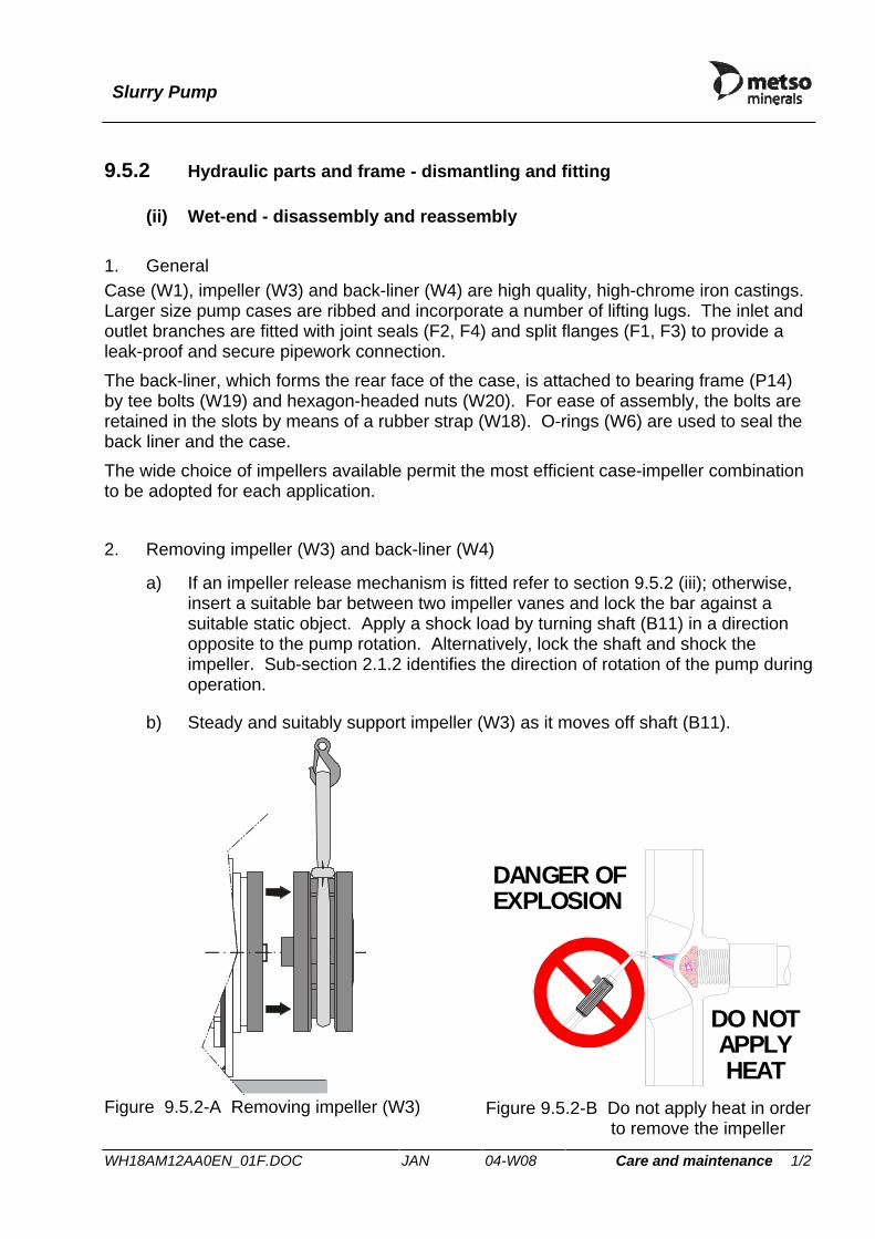
(ii) Wet-end - disassembly and reassembly 1. General Case (W1), impeller (W3) and back-liner (W4) are high quality, high-chrome iron castings. Larger size pump cases are ribbed and incorporate a number of lifting lugs. The inlet and outlet branches are fitted with joint seals (F2, F4) and split flanges (F1, F3) to provide a leak-proof and secure pipework connection. The back-liner, which forms the rear face of the case, is attached to bearing frame (P14) by tee bolts (W19) and hexagon-headed nuts (W20). For ease of assembly, the bolts are retained in the slots by means of a rubber strap (W18). O-rings (W6) are used to seal the back liner and the case. The wide choice of impellers available permit the most efficient case-impeller combination to be adopted for each application. 2. Removing impeller (W3) and back-liner (W4)
a) If an impeller release mechanism is fitted refer to section 9.5.2 (iii); otherwise, insert a suitable bar between two impeller vanes and lock the bar against a suitable static object. Apply a shock load by turning shaft (B11) in a direction opposite to the pump rotation. Alternatively, lock the shaft and shock the impeller. Sub-section 2.1.2 identifies the direction of rotation of the pump during operation.
b) Steady and suitably support impeller (W3) as it moves off shaft (B11).
Figure 9.5.2-A Removing impeller (W3)
DANGER OFEXPLOSION
DO NOTAPPLYHEAT
Figure 9.5.2-B Do not apply heat in order to remove the impeller

Slurry Pump
WH18AM12AA0EN_01F.DOC JAN 04-W08 Care and maintenance 2/2
c) Remove nuts (W20) from the four back liner bolts (W19) and withdraw back liner (W4). The bolts are retained in position by a rubber strap.
WARNING BACK-LINERS ON LARGE PUMPS ARE EXTREMELY HEAVY. USE THE BACK-LINER LIFTING TOOL RECOMMENDED IN SECTION 9.3.
3. Inspection
a) Clean and inspect case (W1), impeller (W3) and back-liner (W4) for severe scoring, extensive wear, pitting, corrosion and damage. Renew if necessary.
b) Inspect back-liner seal (W6). Renew it , if it shows any signs of damage. c) Refer to sections 9.5.3 and 9.5.4 for Shaft Seal and Bearing Maintenance.
4. Assembly
a) Ensure that the impeller release mechanism, where applicable, and the shaft seal components are in position. See parts list drawings in section 10 for details.
b) Fit back-liner seal (W6) into the groove around back-liner (W4). Grease the seal to aid assembly.
c) Locate back-liner bolts (W19) into the lugs around back-liner (W4) and retain in position with back-liner bolt retaining strap (W18).
d) Offer back-liner (W4) to the frame, engaging back liner bolts (W19) in the frame holes.
WARNING WHERE APPLICABLE, USE THE BACK-LINER LIFTING TOOL RECOMMENDED IN SECTION 9.3.
e) Fit and tighten nuts (W20) to the correct torque (refer to sub-section 11.1). NOTE:WHEN FITTING NEW PARTS TO PUMPS FITTED WITH EXPELLER TYPE SHAFT SEALS,
IT MAY BE NECESSARY TO ADJUST THE BEARING ASSEMBLY AXIALLY USING THE ADJUSTING SCREW TO PREVENT THE EXPELLER FOULING THE BACK LINER.
f) Clean the thread on the shaft and grease with appropriate lubricant or anti-seize compound.
g) Fit impeller gasket (W17). h) Lift impeller as shown in Figure 9.5.2-A and mount it onto the shaft end. i) Block impeller (W3) using a bar inserted in between two of its vanes, then turn
the shaft with the special crank-handle until the impeller is locked tight –refer to sub-section 9.3.
j) Set the impeller back clearance, where applicable – see section 9.5.1. k) Apply grease liberally around back-liner seal (W6) to assist entry into case
(W1).

Slurry Pump
WH18IRMAAA0EN_01C.DOC JAN 04-W08 Care and maintenance 1/1
9.5.2 Hydraulic parts and frame - dismantling and fitting
(iii) Impeller Release Mechanism (IRM) Not applicable.
Slurry Pump
WH18HYDAAA0EN_01D.DOC JAN 04-W08 Care and maintenance 1/1
9.5.2 Hydraulic parts and frame - dismantling and fitting
(iv) Hydraulic system
Not applicable
Slurry Pump
WH19AM1G130en_06b.doc JAN 05-W45 Care and maintenance 1/4
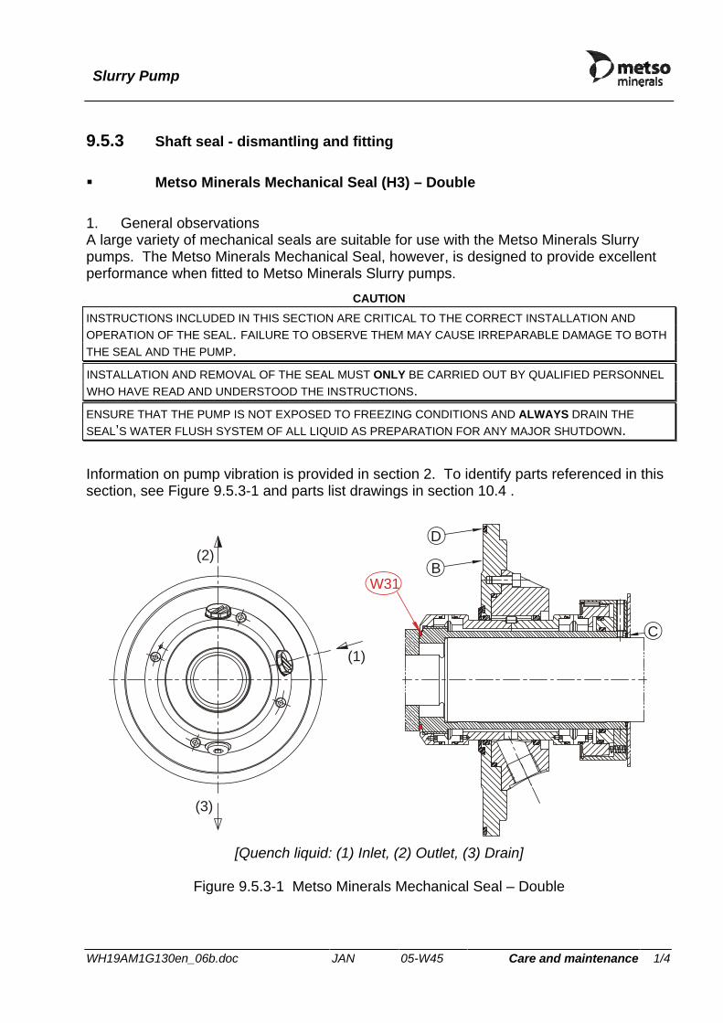
9.5.3 Shaft seal - dismantling and fitting Metso Minerals Mechanical Seal (H3) – Double
1. General observations A large variety of mechanical seals are suitable for use with the Metso Minerals Slurry pumps. The Metso Minerals Mechanical Seal, however, is designed to provide excellent performance when fitted to Metso Minerals Slurry pumps.
CAUTION INSTRUCTIONS INCLUDED IN THIS SECTION ARE CRITICAL TO THE CORRECT INSTALLATION AND OPERATION OF THE SEAL. FAILURE TO OBSERVE THEM MAY CAUSE IRREPARABLE DAMAGE TO BOTH THE SEAL AND THE PUMP. INSTALLATION AND REMOVAL OF THE SEAL MUST ONLY BE CARRIED OUT BY QUALIFIED PERSONNEL WHO HAVE READ AND UNDERSTOOD THE INSTRUCTIONS. ENSURE THAT THE PUMP IS NOT EXPOSED TO FREEZING CONDITIONS AND ALWAYS DRAIN THE SEAL’S WATER FLUSH SYSTEM OF ALL LIQUID AS PREPARATION FOR ANY MAJOR SHUTDOWN.
Information on pump vibration is provided in section 2. To identify parts referenced in this section, see Figure 9.5.3-1 and parts list drawings in section 10.4 .
(2)
(1)
(3)
W31B
D
C
[Quench liquid: (1) Inlet, (2) Outlet, (3) Drain]
Figure 9.5.3-1 Metso Minerals Mechanical Seal – Double

Slurry Pump
WH19AM1G130en_06b.doc JAN 05-W45 Care and maintenance 2/4
2. Operating considerations The double acting Metso Minerals Mechanical Seal has silicon carbide seal faces on both the product and the atmospheric sides. The seal requires flushing liquid at all times during operation, otherwise the seal faces are destroyed within seconds. NOTE: DEPENDING ON THE APPLICATION, THE FLUSHING LIQUID PRESSURE MAY BE EITHER HIGHER
OR LOWER THAN THE PUMP PRESSURE. Flushing rate varies with shaft diameter, D, as shown in Figure 9.5.3-2. Total flushing rate, Tf, is, however, dependent on both the shaft running speed, R, and shaft diameter, D (See Table 9.5.3-1), and is calculated using the formula:
Total flushing rate, Tf = F × Rf Where, Rf , is the shaft speed factor as tabulated in Table 9.5.3-2.
Frame Size Shaft Diameter (mm) FR250 47.5 FR300 63.0 FR400 75.0 FR500 95.0 FR600 111.7 FR750 120.0
Table 9.5.3-1 Frame size to shaft diameter correspondence table (Frame size for your pump is stated in ‘Pump Specification’, section 1.3).
0
1
2
3
4
5
6
0 25 50 75 100 125 150
Shaft diameter, D (mm)
Flus
hing
rate
, F (l
/min
)
Figure 9.5.3-2 Variation of flushing rate with shaft diameter

Slurry Pump
WH19AM1G130en_06b.doc JAN 05-W45 Care and maintenance 3/4
The required water quality is specified as follows:
Table 9.5.3-2 Shaft speed factor table
a) Ensure that quench liquid is present at all times.
NOTE:SEALING LIQUID (WATER) MUST BE CIRCULATED AT 1 TO 2 BAR ABOVE SEAL PRESSURE. CAUTIONS
THE MECHANICAL SEAL MUST NOT RUN WITHOUT QUENCH LIQUID, OTHERWISE THE SEAL WILL BE DESTROYED WITHIN SECONDS.
MINIMUM FLUSHING RATE IS 0.5 LITRES PER MINUTE.
MAXIMUM PUMPING TEMPERATURE IS 75 °C.
b) Check the leakage level of the seal periodically during operation. This is a measure of the condition of the seal. If there is noticable leakage from the seal, it should be renewed. It is recommended that a spare seal is held in stock to allow immediate renewal. No maintenance is possible while the seal is installed.
3. Start-up Before start-up, ALWAYS ensure that liquid is present in the quench system and that it is fully vented.
4. Disassembly
a) Follow the appropriate procedure to stop the pump and isolate it from the power supply.
b) Flush the pump with clean water. c) Close the inlet and discharge valves and drain the pump.
R (rpm) Rf R (rpm) Rf 700 0.2 3950 1.1 1150 0.3 4200 1.2 1400 0.4 4900 1.4 1750 0.5 5250 1.5 2100 0.6 5600 1.6 2450 0.7 5950 1.7 2800 0.8 6300 1.8 3150 0.9 6650 1.9 3500 1.0 7000 2.0
Solid particles : max. 10 mg/l Particle size : 10-50 µm Critical particle size : 2 -5 µm (to be avoided) Permanganate value : max. 30 (free from humus)Ferro content : max. 1 mg/l Hardness value : max. 10° dH
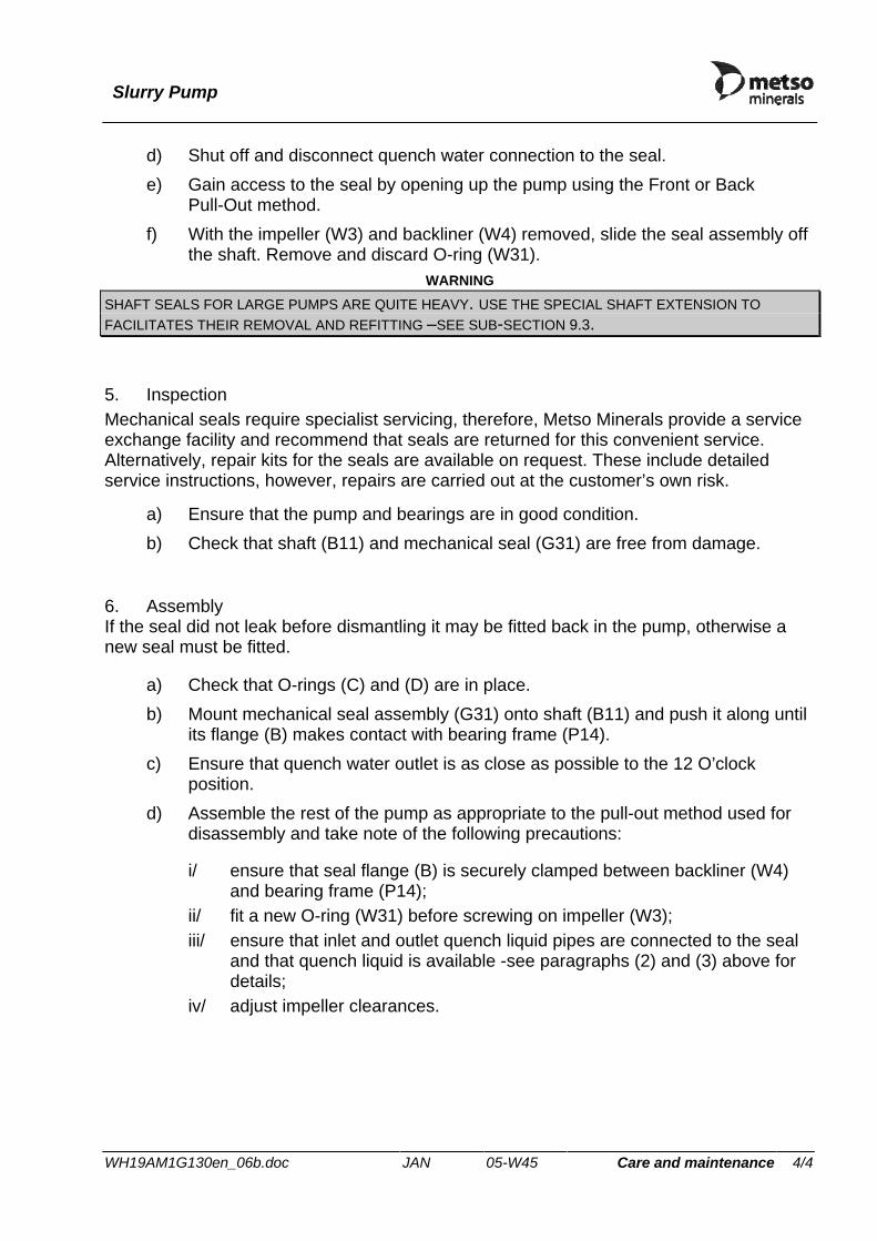
Slurry Pump
WH19AM1G130en_06b.doc JAN 05-W45 Care and maintenance 4/4
d) Shut off and disconnect quench water connection to the seal. e) Gain access to the seal by opening up the pump using the Front or Back
Pull-Out method. f) With the impeller (W3) and backliner (W4) removed, slide the seal assembly off
the shaft. Remove and discard O-ring (W31). WARNING
SHAFT SEALS FOR LARGE PUMPS ARE QUITE HEAVY. USE THE SPECIAL SHAFT EXTENSION TO FACILITATES THEIR REMOVAL AND REFITTING –SEE SUB-SECTION 9.3.
5. Inspection Mechanical seals require specialist servicing, therefore, Metso Minerals provide a service exchange facility and recommend that seals are returned for this convenient service. Alternatively, repair kits for the seals are available on request. These include detailed service instructions, however, repairs are carried out at the customer’s own risk.
a) Ensure that the pump and bearings are in good condition. b) Check that shaft (B11) and mechanical seal (G31) are free from damage.
6. Assembly If the seal did not leak before dismantling it may be fitted back in the pump, otherwise a new seal must be fitted.
a) Check that O-rings (C) and (D) are in place. b) Mount mechanical seal assembly (G31) onto shaft (B11) and push it along until
its flange (B) makes contact with bearing frame (P14). c) Ensure that quench water outlet is as close as possible to the 12 O’clock
position. d) Assemble the rest of the pump as appropriate to the pull-out method used for
disassembly and take note of the following precautions:
i/ ensure that seal flange (B) is securely clamped between backliner (W4) and bearing frame (P14);
ii/ fit a new O-ring (W31) before screwing on impeller (W3); iii/ ensure that inlet and outlet quench liquid pipes are connected to the seal
and that quench liquid is available -see paragraphs (2) and (3) above for details;
iv/ adjust impeller clearances.

Slurry Pump
WH201A1B010EN_01E.DOC JAN 04-W08 Care and maintenance 1/2
9.5.4 Shaft and bearing assembly - removal and fitting The following instructions assume that the pump is installed complete with the drive unit and is connected to the suction and discharge pipework. 1. Removal
a) Remove the drive safety guard and disconnect the drive belts or drive coupling as applicable.
b) If necessary, remove the drive motor to provide sufficient space to withdraw the bearing frame assembly from the case.
c) Remove the wet end assembly (refer to sections 9.5.2 & 9.5.3) d) Where applicable, remove impeller release mechanism from the shaft – see
section 9.5.2 (iii). e) Remove the housing clamp (P29) and cover (P24). f) Slacken the tension screws (P23), adjusting screw (P19) and locknut (P38).
Remove the adjusting screw and retaining plate (P22). g) Remove the saddle screws (P20) and lift out the saddle (P18). h) Remove the grease nipple (B13) from the end cover at the wet-end of the shaft. i) Ease the shaft assembly rearwards out of the bearing frame. When possible,
especially on the larger pumps, fit a strop sling around the bearing housing to take the weight as it is withdrawn completely from the frame. Remove the tension block (P21) as the assembly is withdrawn.
j) Place the shaft and bearing assembly on suitable supports, ideally wooden vee blocks.
2. Re-fitting
a) Clean and degrease the bore of the bearing frame. Coat the machined surfaces with anti-seize compound.
b) Using a suitable strop sling to lift the assembly, insert the shaft and bearing assembly, threaded end first, into the bore of the frame.
c) Rotate the bearing cylinder housing in the frame so that the tapped holes for the saddle screws are uppermost. Fit the following parts into position:
• Tension Block (P21) • Adjusting Screw (P19) into the saddle • Saddle (P18) (Do not fit screws at this stage) • Retaining Plate (P22) • Housing clamps (P29) and Housing clamp screws (P16) - tighten temporarily.
d) Finally, position the bearing cylinder housing so that the saddle screws (P20) can be inserted and fully tightened to the correct torque. See section 11.1.
Slurry Pump
WH201A1B010EN_01E.DOC JAN 04-W08 Care and maintenance 2/2
e) Fit the grease nipple (B13) to the end-cover at the wet-end of the shaft. f) Where applicable, assemble impeller release mechanism to the shaft – see
section 9.5.2 (iii). g) Reassemble the gland. h) Reassemble the remainder of the pump.

Slurry Pump
WH202A1B011EN_01D.DOC JAN 04-W08 Care and maintenance 1/5
9.5.5 Shaft and bearings - disassembly and re-assembly 1. General The bearing assembly consists of a steel shaft onto the end of which the impeller is screwed. The other end of the shaft is keyed to accept a coupling or belt drive arrangement.
Heavy-duty, tapered roller bearings are used in various configurations as illustrated schematically below:
G SGS
Standard bearing assembly
G SGS
Double dry-end bearing assembly for high belt loads
G SGS
Double wet-end bearing assembly for high impeller loads
A lipseal backed by a V-ring (S), seals the bearings against dirt and other foreign matter. Grease nipples (G) are fitted to allow periodic bearing lubrication. Grease is purged through the bearing to remove any contamination.
The bearing assembly is secured in the bearing frame by a housing clamp, saddle block, and adjusting screw. On larger size pumps, two housing clamps and two saddle blocks with adjusting screws are used to adjust the shaft assembly axially.
The central portion of the bearing housing is colour coded to allow the assembly type to be ascertained from the exterior. The band is visible, when the cover plate (P24) is taken off the bearing frame (P14). Table 9.5.5-1 explains the coding.

Slurry Pump
WH202A1B011EN_01D.DOC JAN 04-W08 Care and maintenance 2/5
Table 9.5.5-1 Bearing assembly type colour coding UNIT TYPE STATUS COLOUR CODE
Standard New build Mid Blue-18.E.53
Double dry-end New build Green
Double wet-end New build Yellow
Standard Reconditioned Red
Double dry-end Reconditioned Red with green band
Double wet-end Reconditioned Red with yellow band 2. Disassembly
a) Remove the flinger (B1) from the wet-end of the bearing cylinder. b) Support the shaft and bearing assembly vertically on blocks on the end cover
with the impeller thread downwards. c) Remove the following parts from the dry-end of the bearing cylinder housing
(B14):
• End Cover Screws (B5) • End Cover (B2.2) • Primary (B22.2 ) and secondary (B19.2) seals. NOTE: MAKE A NOTE OF THE NUMBER OF SHIMS FITTED, TO AID ASSEMBLY.
d) Lift out the shaft and bearings. e) Tap or press off the bearings.
NOTE:THREE-BEARING ASSEMBLIES HAVE AN INNER AND OUTER SPACER FITTED BETWEEN THE BEARINGS AT THE TWO-BEARING END.
f) Lay the bearing cylinder housing horizontally on vee blocks. g) Remove the end cover and shims from the wet-end. h) Wash all parts in a suitable cleaning solvent and dry carefully.
3. Inspection
a) Inspect the bearing housing internally for excessive wear in the area of the roller bearing outer races. Check that all threaded holes are clear and that the threads are undamaged.
b) Check for damaged seals. Inspect end covers for damage and ensure that grease passages are clear.

Slurry Pump
WH202A1B011EN_01D.DOC JAN 04-W08 Care and maintenance 3/5
c) Carefully inspect the roller bearings, cages and races for wear, damage and corrosion. After inspection, dip the bearings in gear oil and wrap them in a clean cloth or paper to protect them until installation.
d) Check the condition of the shims. e) Examine the shaft for damage and corrosion. Remove any nicks and burrs with
a carborundum stone. f) Inspect the shaft sleeve and gaskets for deterioration, damage and wear.
Renew any gaskets which are suspect. g) Renew any defective components.
4. Assembly
a) Slide the bearing inner races and bearing cages onto shaft (B11). Ensure that the large outer diameter of the inner races are facing inwards on the shaft. NOTE: ON ASSEMBLIES WITH TWO BEARINGS AT ONE END, THE ARRANGEMENT IS AS
FOLLOWS: INNER RACE, INNER SPACER, OUTER RACE, OUTER SPACER, INNER RACE.
b) Press the bearing inner races onto the shaft so that they are tight against the inner shoulders of the shaft. NOTE: THE BEARINGS MAY BE HEATED IN OIL OR IN A BEARING HEATER TO A MAXIMUM
OF 121 °C FOR EASE OF ASSEMBLY.
c) Coat the shaft between the bearings with a suitable corrosion preventive solution.
CAUTION DO NOT GREASE THE BEARING LANDS OF THE BEARING HOUSING. THESE LANDS SHOULD BE CLEANED WITH A PROPRIETARY DEGREASANT AND THOROUGHLY DRIED. ENSURE THAT THE LANDS ARE FREE FROM ALL DIRT, GRIT AND CONTAMINANTS BEFORE ASSEMBLING.
d) Push or tap a bearing outer race into the bearing cylinder housing (B14) at the end nearest the tapped saddle screw (P20) location holes (wet-end) and position it just below the end face of the housing. The smaller inner diameter must be outermost. See the assembly diagram for correct orientation if in doubt. Stand the housing on one end to assist assembly.
e) Fit grease nipples (B13) to end covers, if not already fitted. Purge greaseways with fresh grease using a grease gun and wipe excess grease away. Ensure that the end covers are kept clean.
f) Fit the secondary seal (B19.1) into the end-cover. g) Place one thick end-cover shim over the spigot of end-cover (B2.1) and fit it to
bearing cylinder housing (B14) using screws (B5) so as to push the outer bearing race into the housing. Position the end-cover so that the bearing

Slurry Pump
WH202A1B011EN_01D.DOC JAN 04-W08 Care and maintenance 4/5
grease hole will be accessible when the bearing cylinder assembly is fitted to bearing frame (P14). Tighten the screws (B5) evenly and to the correct torque. See Torque Table, section 11.1.
h) Fit shaft (B11) into bearing cylinder housing (B14) with its threaded end protruding from the wet-end cover (B2.1). It is recommended that the housing is supported vertically in a secure stand to give sufficient clearance underneath the shaft –see Figure 9.5.5-1.
AB
D
CEE
Figure 9.5.5-1 Bearing cylinder housing support & bearing clearance: Shaft(A),
Dial test indicator (B), Bearing cylinder housing (C), Support stand (D), Securing screws (E).
i) Fit the bearing outer race into the bearing cylinder housing at the dry-end and press it into position using dry-end cover (B2.2) until the shaft becomes stiff to turn.
j) Assemble the pack of shims removed during disassembly. k) Remove cover (B2.2), fit the shims over the cover’s spigot, then re-fit the cover
to the housing.
l) Tighten screws (B5) evenly and to the correct torque. IMPORTANT NOTE
STRIKE THE INDIVIDUAL ENDS OF THE SHAFT TO ENSURE THAT THE BEARING RACES ARE HARD UP AGAINST THE END COVER BEFORE CHECKING THE BEARING CLEARANCE.

Slurry Pump
WH202A1B011EN_01D.DOC JAN 04-W08 Care and maintenance 5/5
Table 9.5.5-2 Bearing clearances
FRAME SIZE CLEARANCE (END-FLOAT), MM FR250 0.075 to 0.125 FR300 0.075 to 0.125 FR400 0.100 to 0.150 FR500 0.100 to 0.150 FR600 0.150 to 0.200 FR750 0.180 to 0.250
m) Check the bearing clearance for the size of pump (See Table 9.5.5-2) using a dial test indicator on the shaft end.
NOTE:IDEALLY, THE INDICATOR SHOULD BE FITTED TO A MAGNETIC BASE LOCATED ON THE END-COVER. BY MOVING THE SHAFT BACKWARDS AND FORWARDS THE END CLEARANCE MAY BE READ ON THE INDICATOR (SEE FIGURE 9.5.5-1).
n) Remove or add shims as necessary to obtain the correct clearance. NOTE:ROTATE THE SHAFT WHILE CHECKING THE CLEARANCE TO ENSURE CORRECT
SEATING OF THE BEARING ROLLERS. o) Having set the clearance, remove dry-end cover (B2.2) and its shim set. p) Remove the dry-end bearing outer race and withdraw the shaft assembly. q) Pack the required quantity of grease into both bearing cages -see Lubrication
sub-section 9.4. NOTE:WHEN HAND PACKING, FORCE GREASE THROUGH THE BEARING UNDER THE CAGE
FROM THE LARGE TO THE SMALL END TO ENSURE THOROUGH DISTRIBUTION. ALWAYS USE THE CORRECT QUANITY OF GREASE. OVER OR UNDER GREASING CAN BE DETRIMENTAL TO THE LIFE OF THE BEARING.
r) Re-fit shaft (B11) into bearing cylinder housing (B14). s) Re-fit the dry-end bearing outer race into the housing. t) Fit secondary seal (B19.2) into end cover (B2.2). u) Fit the shims and refit end-cover (B2.2) to the housing, positioning the grease
hole such that it will be accessible when the bearing cylinder assembly is fitted to bearing frame (P14).
v) Tighten screws (B5) evenly and to the correct torque. w) With the bearing cylinder housing now supported horizontally, lubricate the
parts with grease and slide the shaft spacer (B6) with the shaft spacer seal (B16) into position taking care not to damage the seal. Apply a light coating of grease to the backs of the secondary seals (B19.1) & (B19.2) and push the primary seals (B22.1) & (B22.2) into position making firm contact with the secondary seals.
x) Fit the flinger (B1).

Slurry Pump
WH21AAAD010EN_03B.DOC JAN 04-W08 Care and maintenance 1/6
9.5.6 Pump drive - removal and re-fitting
• V-drive
1. Dismantling the drive WARNING
ENSURE THAT THE PUMP MOTOR IS ISOLATED AND THE ISOLATOR IS LOCKED IN THE ISOLATED POSITION BEFORE REMOVING THE DRIVE GUARD. TO PREVENT 'REVERSE MOTORING' OF THE PUMP, ENSURE THAT THE DISCHARGE LINE IS ISOLATED BEFORE REMOVING THE DRIVE GUARD.
a) Slacken off the screws securing the upper drive guard to the lower and remove the upper drive guard;
b) slacken off the motor support nuts, thus allowing the drive motor to move toward the bearing frame and slackening the drive belts, until the belts can easily be removed by hand;
c) remove the drive belts; d) remove the pump and motor pulleys as described in Pulley – removal; e) remove the drive guard set screws and washers and lift the lower drive guard
from the assembly; f) if required, the motor, or motor and support plate assembly, may be removed
from the pump unit. 2. Reassembling the drive The procedure is as follows;
a) fit the motor and/or motor support plate if these have been removed; b) fit the lower drive guard to the pump unit and, ensuring the guard butts against
the top of the upper bearing housing cover, secure it in position using the drive guard set screws and washers;
c) check that the motor butts against the underside of the lower drive guard. If this is not so then slacken off the motor mounting nuts and bolts, move the motor so that it butts against the lower drive guard, and tighten the motor mounting nuts and bolts on completion;
d) fit the pump pulley as described in Pulley - fitting, ensuring a clearance of approximately 10mm between the underside of the pulley and the lower drive guard;
e) fit the motor pulley as described in Pulley - fitting, ensuring that it is correctly aligned with the pump pulley as described in Drive alignment;
f) fit the drive belts and tension as described in Drive belt tension; g) fit the upper drive guard to the lower and secure in place using the screws
provided.

Slurry Pump
WH21AAAD010EN_03B.DOC JAN 04-W08 Care and maintenance 2/6
3. Pulley – removal
a) Slacken, by several turns, all screws in the Taper Lock® bush. Remove one or two, according to the number of jacking holes (shown as ‘!’ in Figure 9.5.6-1).
b) Oil the thread of each screw, the point of grub screws and under the head of cap screws. Insert the screws into the jacking holes.
c) Tighten the screws alternately until the bush is loosened in the pulley and the assembly is free on the shaft.
d) Withdraw the pulley, complete with Taper Lock® bush.
Figure 9.5.6-1 Taper Lock ® screw positions 4. Pulley - fitting
a) If a new pulley is to be fitted then remove the protective coating from the bore and outside of the Taper Lock® bush, and bore of the pulley;
b) ensure that the mating tapered surfaces are completely clean and free from oil or dirt, insert the bush into the pulley so that the holes are aligned;
c) sparingly oil the thread and point of grub screws, or thread and under the head of cap screws; place the screws loosely in holes in the pulley, shown as ' ' in Figure 9.5.6-1;
d) clean the shaft, fit the key (if used), and fit the pulley to the shaft as one unit, locating in the desired position (note that the bush will nip the shaft first and the pulley will be drawn onto the bush as the screws are further tightened);
e) using a suitable hexagon wrench, tighten the screws gradually and alternately until the torque loading given in Table 9.5.6-1 is achieved;
f) using a suitable block to protect the bush, hammer against the large-end of the bush (this ensures that the bush is seated squarely in the bore of the pulley);
g) re-tighten the screws to the torque specified in Table 9.5.6-1;
Bush size 1008 1108 1210 1610 1615 2012 2517 3020 3030 3525 4030 4535 5040
Torque(Nm) 5.6 5.6 20 20 20 30 50 90 90 115 170 190 270Screws qty 2 2 2 2 2 2 2 2 2 3 3 3 3
size (BSW)
¼" ¼" 3/8" 3/8" 3/8" 7/16" ½" 5/8" 5/8" ½" 5/8" ¾" 7/8"
Table 9.5.6-1 Taper Lock® screw torque loading
h) repeat the hammering and tightening a further once or twice to achieve maximum grip on the shaft;
i) after the drive has run under load for a short time, stop the pump and check the screws for tightness;

Slurry Pump
WH21AAAD010EN_03B.DOC JAN 04-W08 Care and maintenance 3/6
j) fill the empty holes with grease to exclude dirt and other arisings. 5. Drive belt re-fitting
CAUTION DO NOT USE WEDGES, LEVERS ETC. TO FORCE DRIVE BELTS INTO POSITION. THIS PRACTICE WILL RESULT IN INTERNAL DAMAGE TO THE BELTS AND PREMATURE BELT FAILURE.
a) Ensure that the motor support nuts are slackened sufficiently to allow the drive belts to be fitted to the pulleys by hand and fit the drive belts;
b) tension the drive belts as described in Drive belt tension; c) ensure that the pulleys are correctly aligned as described in Drive alignment; d) lock the drive motor in position by tightening the motor support nuts on the
bearing frame side, and recheck the alignment and tension; e) fit the upper drive guard to the lower and secure in position with the screws
provided. 6. Drive belt tension The high performance of modern belts, particularly wedge belts, cannot be achieved without correct tensioning. To check for correct tension, refer Figure 9.5.6-2 and Table 9.5.6-2 and proceed as follows:
a) Install the belts to be a snug fit around the pulleys; b) Spin the pulleys 3-4 revolutions to bed belts into the pulley grooves. c) Multiply the distance between the motor and pump pulley centres (in metres) by
16. This gives the deflection distance in millimetres. d) For belts already in service, the belt tension is correct when on applying the
appropriate ‘basic’ setting force at right angles to one belt at the centre of the span, the belt deflects by the previously calculated distance.
NOTE:FOR SINGLE BELT DRIVES PLACE A STRAIGHT EDGE ACROSS THE TWO PULLEYS TO ACT AS A DATUM FOR MEASURING THE AMOUNT OF DEFLECTION. TO CHECK TENSION IN BANDED BELTS, USE A BAR ACROSS THE BAND WIDTH TO ENSURE EVEN DISTRIBUTION OF THE FORCE. THEN DIVIDE THE FORCE MEASURED BY THE NUMBER OF BELTS IN THE BAND FOR COMPARISON WITH THE VALUES IN THE TABLE. FOR SHORT CENTRE DISTANCE DRIVES WHERE THE DEFLECTION OF THE BELT IS TOO SMALL TO MEASURE ACCURATELY, DOUBLE BOTH THE DEFLECTION AND THE SETTING FORCE VALUES.
e) If a new belt is being installed, tension it to the ‘1.25×’ setting. f) Refit the guards and run the drive under load for 15 to 20 minutes. g) Stop the drive, check the tension as previously described and re-set to the
‘basic’ value, if necessary. NOTE:COGGED RAW EDGED BELTS SHOULD BE RESET TO ‘1.25× ‘SETTING
h) There should be no need for further attention during the life of the belts.
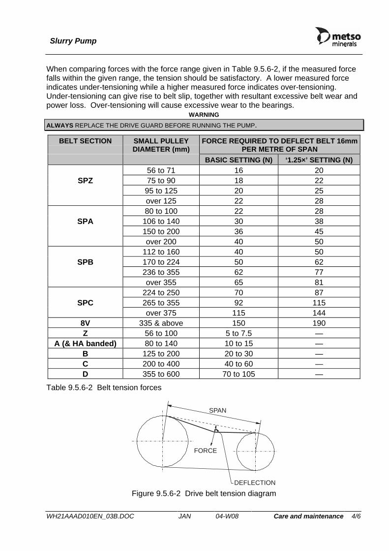
Slurry Pump
WH21AAAD010EN_03B.DOC JAN 04-W08 Care and maintenance 4/6
When comparing forces with the force range given in Table 9.5.6-2, if the measured force falls within the given range, the tension should be satisfactory. A lower measured force indicates under-tensioning while a higher measured force indicates over-tensioning. Under-tensioning can give rise to belt slip, together with resultant excessive belt wear and power loss. Over-tensioning will cause excessive wear to the bearings.
WARNING ALWAYS REPLACE THE DRIVE GUARD BEFORE RUNNING THE PUMP.
BELT SECTION SMALL PULLEY DIAMETER (mm)
FORCE REQUIRED TO DEFLECT BELT 16mm PER METRE OF SPAN
BASIC SETTING (N) ‘1.25×’ SETTING (N) 56 to 71 16 20
SPZ 75 to 90 18 22 95 to 125 20 25
over 125 22 28 80 to 100 22 28
SPA 106 to 140 30 38 150 to 200 36 45
over 200 40 50 112 to 160 40 50
SPB 170 to 224 50 62 236 to 355 62 77
over 355 65 81 224 to 250 70 87
SPC 265 to 355 92 115 over 375 115 144
8V 335 & above 150 190 Z 56 to 100 5 to 7.5 —
A (& HA banded) 80 to 140 10 to 15 — B 125 to 200 20 to 30 — C 200 to 400 40 to 60 — D 355 to 600 70 to 105 —
Table 9.5.6-2 Belt tension forces
SPAN
FORCE
DEFLECTION Figure 9.5.6-2 Drive belt tension diagram

Slurry Pump
WH21AAAD010EN_03B.DOC JAN 04-W08 Care and maintenance 5/6
7. Trouble shooting
a) Small cracks on V-belt side and base This is generally caused by shortage of belt tension but excessive heat and/or chemical fumes can also give same failure.
b) V-belt swelling or softening This is caused by excessive contamination by oil, certain cutting fluids or rubber solvent.
c) Whipping during running This is usually caused by incorrect tensioning, principally on long centre drives. If a slightly higher (or lower) tension does not cure the problem there may be a critical vibration frequency in the system which requires re-design or use of banded belts.
8. Drive alignment It is important that drive belts are correctly aligned. Belt misalignment results in increased noise, increased power absorption and reduced belt life. Figure 9.5.6-3 shows examples of parallel and angular misalignment.
<4mm/m
<1mm/m
PARALLEL MISALIGNMENT
ANGULAR MISALIGNMENT
Figure 9.5.6-3 Drive belt misalignment The motor and pump pulleys are fitted to their shafts with Taper Lock® bushes. This method allows the pulleys to be fitted at any position on the shaft, subject to certain constraints (length of shaft keyway etc.). However, to reduce bearing loading, it is important that each pulley is fitted close to the motor body/bearing frame. The maximum permitted misalignment for the pump is ±4mm/m run parallel misalignment and ±1° angular misalignment. Details of alignment procedures are given in section (drive assembly - fitting).

Slurry Pump
WH21AAAD010EN_03B.DOC JAN 04-W08 Care and maintenance 6/6
CAUTIONS V-BELTS FROM DIFFERENT MANUFACTURERS MUST NOT BE MIXED ON THE SAME DRIVE. THE SLIGHT DIFFERENCES IN CROSS SECTION AND INTERNAL DESIGN WILL SERIOUSLY AFFECT RUNNING LIFE. FOR THE SAME REASON, NEW AND USED V-BELTS SHOULD NOT BE USED ON THE SAME DRIVE. WHEN REPLACING BELTS, ALWAYS REPLACE THE ENTIRE SET TOGETHER. TO PREVENT ABRASION AND DETERIORATION, THE BELT SYSTEM MUST BE KEPT CLEAN AND FREE FROM EXCESSIVE HEAT, OIL, GREASE AND CHEMICAL FUMES. IF THIS IS NOT POSSIBLE THEN SPECIAL BELTS SHOULD BE SPECIFIED.

Slurry Pump
WH22AAAAAA0EN_03B.DOC JAN 04-W08 Care and maintenance 1/3
9.6 Fault finding
9.6.1 General Use the checklist provided to quickly establish the cause of any running problems. The checklist assumes that the equipment normally operates satisfactorily.
WARNING WHERE POSSIBLE CHECKS MUST BE CARRIED OUT WITH THE POWER SUPPLY SECURELY ISOLATED. WHERE POWER IS REQUIRED FOR CARRYING OUT THE CHECKS, TAKE EVERY PRECAUTION PRESCRIBED IN ORDER TO AVOID INJURY TO PERSONNEL. ELECTRICAL WORK MUST ONLY BE CARRIED OUT BY A FULLY QUALIFIED ELECTRICIAN.
A multimeter, a test lamp and appropriate circuit diagrams will be required to carry out checks on electrical equipment. NOTE: IF ALL FAILS, CONTACT METSO MINERALS FOR FURTHER ADVICE.
9.6.2 Pump fails to start Is power supply live ? No⇒ Check that: Yes ⇓ ⇓ ⇓ ⇓ ⇓
• mains switch is closed; • starter and its fuses are intact; • control voltage is available for starting; • overload protection has been reset; • all phases are live; • power cable to motor is not damaged.
Can pump be started manually ? No⇒ Is there a fault with:
Yes ⇓ ⇓ ⇓
• level control equipment ? • other monitoring or control equipment ? Consult monitoring equipment documentation and change any faulty equipment.
Is the shaft jammed ? Yes⇒ Securely isolate the power supply. No ⇓ ⇓ ⇓
• Remove the belt guard and try to rotate the pump shaft by hand.
• Dismantle the pump and clean behind the impeller. See section 9.5.2. Flush out the pump and the pump sump.
⇓ ⇓ ⇓
• Dismantle the drive and check that both the motor and pump shaft can be rotated. Fit new bearings if necessary. See section 9.5 and the motor manufacturer’s instructions.
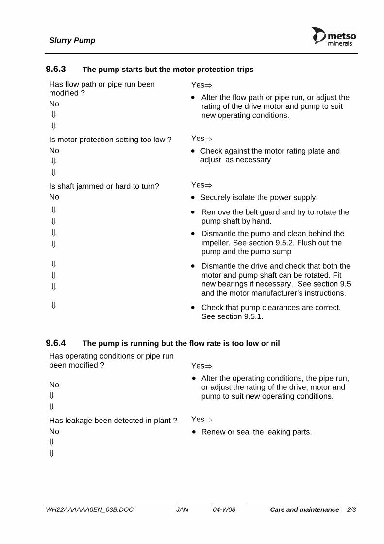
Slurry Pump
WH22AAAAAA0EN_03B.DOC JAN 04-W08 Care and maintenance 2/3
9.6.3 The pump starts but the motor protection trips
Has flow path or pipe run been modified ? No ⇓ ⇓
Yes⇒ • Alter the flow path or pipe run, or adjust the
rating of the drive motor and pump to suit new operating conditions.
Is motor protection setting too low ? No ⇓ ⇓
Yes⇒ • Check against the motor rating plate and
adjust as necessary
Is shaft jammed or hard to turn? No
Yes⇒ • Securely isolate the power supply.
⇓ ⇓ ⇓ ⇓
• Remove the belt guard and try to rotate the pump shaft by hand.
• Dismantle the pump and clean behind the impeller. See section 9.5.2. Flush out the pump and the pump sump
⇓ ⇓ ⇓
• Dismantle the drive and check that both the motor and pump shaft can be rotated. Fit new bearings if necessary. See section 9.5 and the motor manufacturer’s instructions.
⇓ • Check that pump clearances are correct. See section 9.5.1.
9.6.4 The pump is running but the flow rate is too low or nil Has operating conditions or pipe run been modified ? No ⇓ ⇓
Yes⇒ • Alter the operating conditions, the pipe run,
or adjust the rating of the drive, motor and pump to suit new operating conditions.
Has leakage been detected in plant ? No ⇓ ⇓
Yes⇒ • Renew or seal the leaking parts.
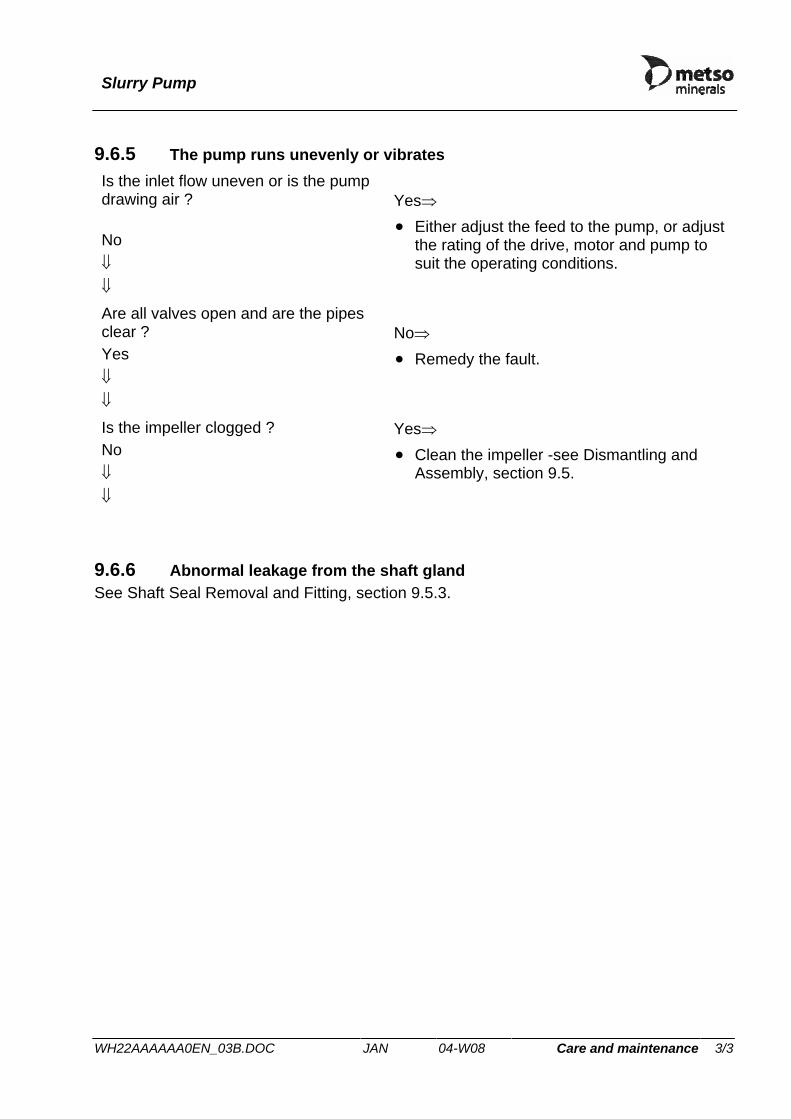
Slurry Pump
WH22AAAAAA0EN_03B.DOC JAN 04-W08 Care and maintenance 3/3
9.6.5 The pump runs unevenly or vibrates Is the inlet flow uneven or is the pump drawing air ? No ⇓ ⇓
Yes⇒ • Either adjust the feed to the pump, or adjust
the rating of the drive, motor and pump to suit the operating conditions.
Are all valves open and are the pipes clear ? Yes ⇓ ⇓
No⇒ • Remedy the fault.
Is the impeller clogged ? No ⇓ ⇓
Yes⇒ • Clean the impeller -see Dismantling and
Assembly, section 9.5.
9.6.6 Abnormal leakage from the shaft gland See Shaft Seal Removal and Fitting, section 9.5.3.

Slurry Pump
WH23AM1S040EN_03C.DOC JAN 04-W08 Spare parts 1/1
10 SPARE PARTS
10.1 Recommended stock of spares To reduce the length of time a pump is out of service, it is advisable to always keep in stock a set of the recommended spare parts listed in this section. Please refer to the table below for part item number references.
Item Part Reference Case (complete volute) W1
Impeller W3
Back-liner W4
Metso Minerals mechanical seal G31
Bearing cylinder assembly B99
Set of seals B98
10.2 Storage of spares See section 1.2.5.
10.3 Spares ordering procedure To assist our Spares Department process your order quickly, customers are requested to provide the following information when ordering spares:
• Model and Size of pump • Serial Number • Build Number • Approximate date of purchase • Part Number and Description of Required Spare Parts
This information should then be forwarded to the local Metso Minerals branch for action - - see sub-section 1.4.

Slurry Pump
WH24AAAAAA0EN_03B.DOC JAN 04-W08 Spare parts 1/1
10.4 Spare part drawing

Slurry Pump
WH24AM1W010XX_02E.DOC JAN 04-W08 Spare parts 1/1
W3
W2
W4
W1
W6
F3 F4
F1
F2
W17
W19
W20
W21
W18
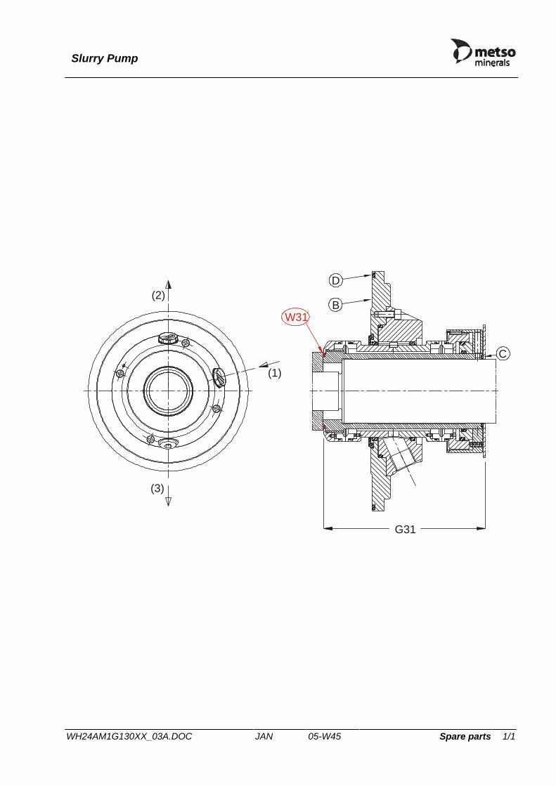
Slurry Pump
WH24AM1G130XX_03A.DOC JAN 05-W45 Spare parts 1/1
(2)
(1)
(3)
W31B
D
C
G31

Slurry Pump
WH24AA1B013XX_04B.DOC JAN 04-W08 Spare parts 1/1
½"B
SP
A A
A-A
B13
B22
.2
B11
B10
B19
.2
B2.2 B5
B3B1
4B1
9.1
B2.1
B1
B6
B16
B22
.1B
8
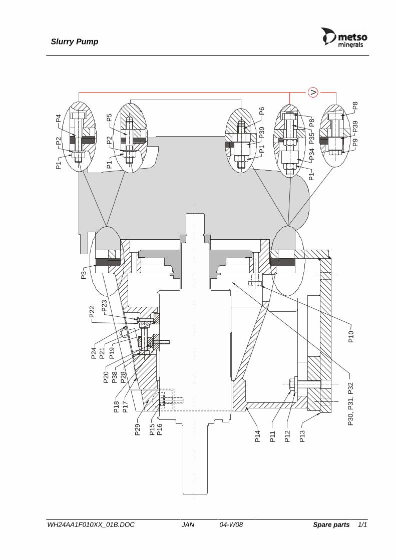
Slurry Pump
WH24AA1F010XX_01B.DOC JAN 04-W08 Spare parts 1/1
P3
P23
P22
P24
P21
P19
P38
P20
P28
P17
P18
P29 P15
P16
P14
P11
P12
P13
P30
, P31
, P32
P10
P5
P2
P1
P4
P2
P1
V
P1
P39
P6
P9
P39
P8
P34
P35
P1
P8

Parts list
26172301000 Edition 1 JAN 06-W29 Spare parts 1/1
Item Part No. Description Qty Unit weightKg
Pump HM100 MEC HC
Wear partsW01 PD771010 Case 1 77.00W03 PD731047 Impeller 1 23.00W04 PD741041 Back liner 1 13.80W06 SA982898 O-ring (incl. in w04) 1 0.00
Shaft sealG31 SABA063-P-NPT Mechanical seal 1 0.00
Bearing assembly partsB01 SA500218-2 Flinger 1 0.35B02.1 PDCH1843-SS End cover 1 1.30B02.2 PDCH3074-SS End cover 1 1.80B03 PD720025 Shim set 1 0.00B06 PDCB810 Shaft spacer 1 0.20B08 Z0370576 Bearing 2 2.00B10 SA899018-130 Key 1 0.00B11 PDCH1844 Shaft 1 17.80B14 PD720004 Bearing cylinder housing 1 16.50B99 PDWB041-S464 Bearing/shaft assembly 1 44.00
Spare parts
B16 SA953171 O-ring 1 0.00B19.1 Z3014475 Lipseal 1 0.00B19.2 Z30142617 Lipseal 1 0.00B22.1 SA955005 V-ring 1 0.00B22.2 SA953325 V-ring 1 0.01P03 PD720097-SS Shim set 22 0.00P04 PD760040-FZV Case bolt 6 0.33P08 PD720015-FZV Casing nut 2 0.25P39 PDCA43-2FZV Spacer 2 0.13W18 SA981223 O-ring 1 0.00W19 PD720040-FZV Back liner bolt 4 0.00
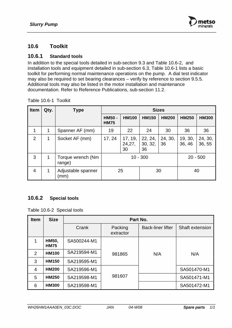
Slurry Pump
WH26HM1AAA0EN_03C.DOC JAN 04-W08 Spare parts 1/1
10.6 Toolkit
10.6.1 Standard tools In addition to the special tools detailed in sub-section 9.3 and Table 10.6-2, and installation tools and equipment detailed in sub-section 6.3, Table 10.6-1 lists a basic toolkit for performing normal maintenance operations on the pump. A dial test indicator may also be required to set bearing clearances – verify by reference to section 9.5.5. Additional tools may also be listed in the motor installation and maintenance documentation. Refer to Reference Publications, sub-section 11.2. Table 10.6-1 Toolkit
Item Qty. Type Sizes HM50 -
HM75 HM100 HM150 HM200 HM250 HM300
1 1 Spanner AF (mm) 19 22 24 30 36 36
2 1 Socket AF (mm) 17, 24 17, 19, 24,27, 30
22, 24, 30, 32, 36
24, 30, 36
19, 30, 36, 46
24, 30, 36, 55
3 1 Torque wrench (Nm range)
10 - 300 20 - 500
4 1 Adjustable spanner (mm)
25 30 40
10.6.2 Special tools Table 10.6-2 Special tools
Item Size Part No. Crank Packing
extractor Back-liner lifter Shaft extension
1 HM50, HM75
SA500244-M1
2 HM100 SA219594-M1
3 HM150 SA219595-M1
981865
N/A
4 HM200 SA219596-M1
N/A
SA501470-M1
5 HM250 SA219598-M1 SA501471-M1
6 HM300 SA219598-M1
981607
SA501472-M1

Slurry Pump
WH26HM1AAA0EN_03C.DOC JAN 04-W08 Appendices 2/2
11 APPENDICES
11.1 Torque table The following table gives the recommended torque values for tightening bolts and screws. NOTE: ALL TORQUE VALUE TOLERANCES ARE ±5%.
TORQUE VALUES (Nm) ITEM HM50 HM75 HM100 HM150 HM200 HM250 HM300
Case bolt (P4) 147 147 163 189 189 270 370
Casing clamp screw (P9) 147 147 163 189 189 270 370
Bearing frame screw (P11) 163 163 163 177 189 338 370
Back-liner bolts (W19) 34 34 34 54 98 142 142
Housing clamp screws (P16) 34 34 40 54 67 80 80
Tension screws (P23) 16 to 18 16 to 18 16 to 18 16 to 18 26 to 34 26 to 34 26 to 34
Saddle screws (P20) 34 34 40 54 54 108 142
End-cover bolt (B5) 34 34 40 40 54 81 126
Outlet flange half-clamp bolts NP16 (F3)
20(M8)
40(M10)
70(M12)
170(M16)
170(M16)
170(M16)
170(M16)
Inlet flange half-clamp bolts NP16 (F1)
20(M8)
70(M12)
170(M16)
170(M16)
170(M16)
170(M16)
170(M16)

Slurry Pump
WH26HM1AAA0EN_03C.DOC JAN 04-W08 Appendices 3/2
11.2 Reference publications Thermosiphon System non-pressurised

Slurry Seal
3.2 JAN 02-W17 Edition 5 6/14
B= closed system (non-pressurised) Option 5 Thermosiphon System non-pressurised Double Seals & Single seals Unit Drawing number Theromsiphon system 142.12601.SE 10l Suitable When mains water is not present and double seal or single seal with low quench is needed. Or when a separate system is needed because of the process conditions. This system shall operate non-pressurised. Any leakage of the inner seal will be in to the thermosiphon system; therefore it’s important to monitor the level in the tank. If increasing there is a leakage on the inner seal and product will enter the system. If the level is decreasing there is leakage on the secondary seal to the atmosphere. There is only thermosiphon that makes circulation on the barrier, and therefore it is important that the system is fitted minimum 1-2m vertically above the seal chamber. Avoid connecting pipe work with sharp bends. If level in the tank is below connection from seal to the tank, thermosiphon circulation will stop. For water quality, pressures see assembly instructions for the seal. Benefits Simple open system in stainless steel to be used for low quenching including, sight glass, (see drawing 142.12601.SE) that provides a reliable condition for the seal to Work in. The system keeps the primary seal (primary seal is operating on product) clean and protects the secondary seal from dry running. There is also a cooling effect that keeps the temperature down. Exclude reaction from the product with oxygen in the air. The system can not be pressurised.
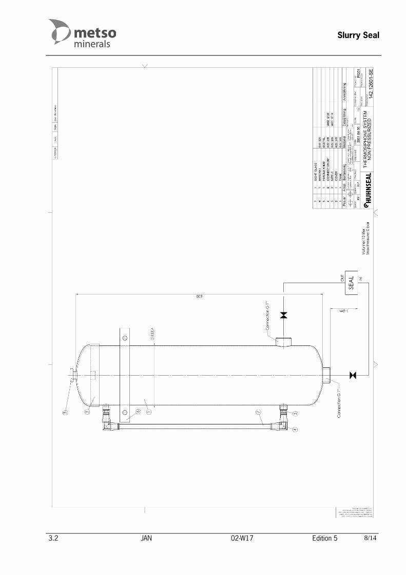
Slurry Seal
3.2 JAN 02-W17 Edition 5 8/14

Slurry Pump
WH27HM11000EN_03B.DOC JAN 04-W08 Appendices 1/1
11.3 Weights table
Item Description Weight (kg) - Bare shaft pump 315
W1 Case 80
P14 Frame 86
B99 Bearing cylinder assembly 45
- Back pull-out assembly 198