Installation Operation Maintenance - Trane · PDF fileInstallation Operation Maintenance Series R

Operation & Maintenance Manual
VHC & VLC Series Unit Ventilator
Form SC-OM-MANUAL rev 1 ©2005 Temspec Incorporated
IMPORTANT: Read and save this manual for future reference. This manual is to be left with the equipment owner
Table Of Contents
INTRODUCTION About the Unit Ventilator ….……………………………………………………………………1 Nomenclature for Unit Ventilators with Self-Contained Cooling ….……………………1
TYPICAL UNIT LAYOUT Model VLC 24, VLC 30, VLC 36 .………………………………………………………………2 Model VLC 48, VLC 60 - (ducted) ….……………………………………………………………3 Model VLC 48, VLC 60 - (freeblow) .………………………………………………………4 Model VHC 30, VHC 36, VHC 48, VHC 60 .………………………………………………5
OPERATION Sequence of Operation ..………………………………………………………………………6 Hot Water Circuit .……………………………………………………………………………….7 Refrigeration Circuit ………....……………………………………………………………………..8 Electrical Circuit ……….….……………………………………………………………………9 Dampers ……….………….……………………………………………………………………9 Optional Powered Exhaust ….………….…………………………………………………………9 Filtration ……….………….………………………………………………………………..…..9
MAINTENANCE Servicing the Unit ………….………….………………………………………………………..10 Maintenance Schedule ….………….……………………………………………………..…10 Changing the Filters ………….………….……………………………………………………..…11 Cleaning the Condenser Coil …….………………………………………………….…..…11 Cleaning the Evaporator Coil …….………………………………………………………...12 Motors ………………………….…………………………………………………………...12
TROUBLESHOOTING Basic Troubleshooting Guidelines …..…………………………………………………………..13
REPLACEMENT PARTS Limited Warranty ..……………………...………………………………………………………14 Part Sales …………..………………………..…….…………………………………………....14

INTRODUCTION
The Temspec unit ventilator was designed as a means for providing heating, cooling and ventilation to the classroom. Our goal is to help create an enhanced learning environment by focusing on the following points when designing our equipment:
• TEMPERATURE & HUMIDITY CONTROL
• AIR DISTRIBUTION
• SOUND ATTENUATION By introducing the vertical unit ventilator into the classroom, superior control can be obtained for each room. Because of the unit’s ducting capabilities, an even distribution of air can be achieved throughout the room. The unit ventilator is constructed with heavy guage metal and sound absorbing insulation for optimal sound attenuation. By applying sound engineering principles and through continuous testing, the highest quality of performance is obtained in the unit ventilators.
-1-
ABOUT THE UNIT VENTILATOR
NOMENCLATURE FOR UNIT VENTILATORS WITH SELF-CONTAINED COOLING
V LC
Vertical Unit
LC = Low Condensing Section HC = High Condensing Section
36
24 = 2.0 tons of Cooling 30 = 2.5 tons of Cooling 36 = 3.0 tons of Cooling 48 = 4.0 tons of Cooling 60 = 5.0 tons of cooling

TYPICAL LAYOUT
C.A. Condenser Air
O.A. Outdoor Air
1. Barometric relief damper assembly (optional).
2. Hot water coil. Optional electric or steam
coil available.
3. Dual supply air fans.
4. Outdoor air damper.
5. Condenser coil.
6. DX cooling coil.
7. Drain pan.
8. Electrical box / controls enclosure.
9. Mixed air damper actuator.
10. Filter.
O.A.
C.E.
S.A. Supply Air
R.A. Return Air
5
C.A.
SIDE SECTION
23"
13
12
4
3
2
1
E.A.
7
10
11
9
8
S.A.
6
E.A.S.A.
18
E.A. Room Exhaust Air
C.E. Condenser Exhaust Air
11. Return air damper.
12. Single condenser fan.
13. Compressor.
14. Ceiling tile.
15. Top extension /duct shroud to suit
ceiling height (optional).
16. Coil access panel (removable) with optional
double deflection discharge grille.
17. Filter access panel, hinged.
18. Removable access panel.
19. Heavy duty return air grille.
FRONT ELEVATION
19
33"
17
16
15
14
S.A.
Duct By
Others
93"
S.A.
H
R.A.
NOTE: The component arrangement shown above may vary slightly from that in the unit ventilator supplied.
-2-
Models VLC 24, VLC 30, VLC36

TYPICAL LAYOUT
Duct By
Others
O.A. Outdoor Air
C.A. Condenser Air
1. Barometric relief damper assembly (optional).
2. DX cooling coil.
3. Drain pan.
4. Spring return mixed air damper actuator.
5. Outdoor air damper.
6. Condenser coil.
7. Dual supply air fans.
8. Hot water coil. Optional electric or steam
coil available.
9. Electrical box / controls enclosure.
10. Filters.
O.A.
R.A. Return Air
S.A. Supply Air
6
C.E.
C.A.
SIDE SECTION
30"
R.A.
12
13
5
4
2
1
E.A.
E.A.
11
10
7
S.A.
C.E. Condenser Exhaust Air
E.A. Room Exhaust Air
FRONT ELEVATION
19
18
44"
17
16
15
14
93"
H
11. Return air damper.
12. Dual condenser fans.
13. Compressor.
14. Ceiling tile.
15. Top extension / duct shroud to suit
ceiling height (optional).
16. Coil access panel, removable.
17. Filter access panel, hinged.
18. Removable access panel.
19. Heavy duty return air grille.
9
8
3
NOTE: The component arrangement shown above may vary slightly from that in the unit ventilator supplied.
-3-
Models VLC 48, VLC 60 (ducted configuration)

TYPICAL LAYOUT
C.A. Condenser Air
O.A. Outdoor Air
1. Hot water coil. Optional electric or steam
coil available.
2. DX cooling coil.
3. Drain pan.
4. Dual supply air fans.
5. Outdoor air damper.
6. Condenser coil.
7. Supply air grilles (double deflection).
8. Electrical box / controls enclosure.
9. Mixed air damper actuator.
10. Filters.
6
S.A. Supply Air
R.A. Return Air
C.E.
C.A.
SIDE SECTION
30"
12
13
R.A.
5
4
O.A.
2
3
1
11
10
8
7
18
C.E. Condenser Exhaust Air
11. Return air damper.
12. Compressor.
13. Dual condenser fans.
14. Ceiling tile.
15. Top extension to suit ceiling height
(optional).
16. Coil access panel (removable) with front
double deflection grille.
17. Filter access panel, hinged.
18. Removable access panel.
19. Heavy duty return air grille.
FRONT ELEVATION
19
44"
14
17
16
15
93"
H
S.A. S.A. S.A.
9
NOTE: The component arrangement shown above may vary slightly from that in the unit ventilator supplied.
-4-
Models VLC 48, VLC 60 (freeblow configuration)

TYPICAL LAYOUT
O.A. Outdoor Air
C.A. Condenser Air
R.A. / E.A.
1. DX cooling coil.
2. Drain pan.
3. Outdoor air damper.
4. Mixed air damper actuator.
5. Dual condenser exhaust / powered exhaust
fans.
6. Condenser coil.
7. Supply air fan(s).
8. Hot Water Coil. Optional electric or steam
coil available.
9. Electrical box / controls enclosure.
R.A. Return Air
S.A. Supply Air
1.
2
6
SIDE SECTION
30"
13
C.E. / E.A.
C.A.
5
4
3O.A.
1
2
E.A.
12
11
10
7
8
9
S.A.
C.E. Condenser Exhaust Air
E.A. Room Exhaust Air
FRONT ELEVATION
18
17
44"
16
15
14
S.A.
93"
H
10. Filters.
11. Return air damper.
12. Modulating powered exhaust damper
and actuator module (optional).
13. Compressor.
14. Ceiling tile.
15. Top extension / duct shroud to suit
ceiling height (optional).
16. Filter/coil hinged access panel.
17. Removable access panel.
18. Heavy duty return air grille.
NOTE: The component arrangement shown above may vary slightly from that in the unit ventilator supplied.
-5-
Models VHC 30, VHC 36, VHC 48, VHC 60 (ducted configuration)

OPERATION
The following are typical modes of operation for a classroom unit ventilator. Please refer to the manual provided by the controls contractor for a more specific controls sequence.
1. Unoccupied Mode During the “unoccupied heat” mode (night set-back) space temperature is maintained by a signal from the thermostat/controller to either the modulating control valve or electric coil. The powered exhaust damper (if applicable) and the outdoor air damper are fully closed and the return air damper is fully open. The supply air fan operates on call for heating or cooling from the thermostat/controller.
2. Occupied Mode
The unit ventilator is switched to “occupied mode” by the thermostat/controller. In this mode a signal is sent from the thermostat/controller to either the modulating control valve or electric coil to maintain room temperature at set point. The outdoor air damper is held at a minimum position in the heating and mechanical cooling modes. The supply air fan runs continuously.
3. Economizer (up to 100% outdoor air)
The first stage of cooling is the economizer mode during which all stages of heating are off. The outdoor air and the return air dampers modulate to maintain the room temperature at the economizer set point. If the mixed air falls to a programmed temperature (usually 52°F) the outdoor air damper will modulate towards closed until the mixed air temperature rises again (typically to 55°F). In this free cooling mode the ability of the unit ventilator to provide sufficient cooling is limited only by the outdoor air temperature and the total C.F.M. rating of the unit.
4. Mechanical Cooling
The unit ventilator utilizes the self-contained refrigeration section incorporated within the unit (DX coil, condenser coil, compressor and refrigerant expansion device). The system maintains the cooling set point by cycling on call from the thermostat/controller. In this mode the outdoor air damper will return to minimum position.
5. Freeze Protection
For units with a steam or hot water coil, freeze protection is usually incorporated. This can be by either a low limit temperature control (autoreset or manual reset) or by using a supply air sensor and programming from the controller. When a mixed air temperature is determined to be too low, then the outdoor air damper will close and the control valve will fully open. The fan can also be shut down until the temperature returns to normal levels. The low limit temperature control (freezestat) should be located at the leaving air side of the heating coil.
6. Humidistat & Hot Gas Reheat (Optional for VHC series units only)
A room humidistat sensor is included in the return air stream. The humidistat has a set point of 55% R.H. (adjustable). When the room temperature falls to the cooling set point and the humidistat set point has not been satisfied, the hot gas reheat coil provides reheat to maintain the cooling set point in the room (to avoid over cooling in the space). The compressor operates under this condition. When the humidity set point is satisfied, the reheat coil is de-energized.
-6-
Typical Modes Of Operation

The following are typical hot water piping schematics for a unit ventilator. Please refer to the unit ventilator shop drawings for a more specific layout.
Hot Water With 2-way Control Valve
Manual Air Vent
2-way Control Valve
MIXED
AIR HOT
WATER
COIL
Strainer
MV
Isolation Valve
HWS
Isolation Valve
Balancing Valve
HWR
Hot Water With 3-way Control Valve
MIXED
AIR
C
Strainer
HOT
WATER
COIL
NO
NC
3-way Control Valve
Manual Air Vent
MV
Isolation Valve
HWS
HWR
Balancing Valve
Isolation Valve
-7-
Hot Water Circuit

The following is a typical self-contained refrigeration circuit.
EVAPORATOR
COIL
CONDENSER
COIL
OUTDOOR
AIR
MIXED
AIR
Sight Glass, Moisture Indicator
Pressure Test Port
Metering Device
Anti-Ice Control
Distributor
Crankcase Heater
Compressor
Filter Dryer
High Limit Pressure
Cut-Out
Low Limit Pressure
Cut-Out
-8-
Refrigeration Circuit

The electrical circuit in the unit ventilator is dependent on the controller and sequence that is being utilized. The unit can be supplied with a 208V, 277V or 460V power supply. The unit is equipped with an unfused service disconnect. A copy of the electrical schematic can be found folded in a pouch inside of each unit ventilator, located on the electrical enclosure or supply air fan housing.
The outdoor air dampers and return air dampers are mechanically linked. As the outdoor air damper opens, the return air damper closes. A spring return damper actuator is connected to a linkage set that extends to both sets of dampers. The damper actuator manufacturer can vary. Please refer to the wiring schematic for the damper actuator model type.
Internal powered exhaust is an optional feature that is provided with the VHC series. This feature comes with a spring return damper actuator that is separate from the one used to control the outside air and return air dampers. However, the powered exhaust damper actuator is electrically linked to the outside air damper. As the outside air damper opens, so does the powered exhaust damper.
Typically 1” disposable filters are provided in the unit. Please refer to the “shop drawings” for specific details on filter construction and thickness. Below are sizes and quantity per unit for the different model types.
Model Number Filter Size Quantity Per Unit VLC 24, VLC 30, VLC 36 20” x 24” nominal 1 VLC 48, VLC 60 16” x 24” nominal 2 VHC 36, VHC 48, VHC 60 20” x 25” nominal 2
-9-
Electrical Circuit
Dampers
Powered Exhaust (optional)
Filtration

MAINTENANCE
Maintenance to the unit is accomplished by removing the front access panels. Typically the panels are secured by heavy duty phillips (star or cross shape) head screws. When removing the access panel, loosen but do not remove the screws. Carefully store the panel in a place where it will not get damaged. Use caution as some access panels are heavy. CAUTION: Disconnect power at the remote circuit breaker before servicing the
unit. The unit comes fitted with a “fan kill switch” that de-energizes the supply air fan(s) when the filter access panel is removed / opened. This will only disconnect the power to the supply air fans. Be sure to disconnect ALL power by turning the remote circuit breaker to the off position. To access the condenser section, you must remove a secondary panel located directly behind the return air access panel.
Interior and exterior environmental conditions will influence the required frequency of coil cleaning and filter change operations . The following is a typical maintenance schedule for a classroom unit ventilator. Initial Start-Up – Change out construction filters.
– Verify that air paths are free of construction debris and that fans turn freely – Verify compressor rotation – Verify outdoor air minimum position
Every 3 months – Change filters Every 12 months – Clean condenser coil (at the beginning of the cooling season) – Vacuum out evaporator drain pan
– Vacuum any loose debris from unit’s interior condenser section – Clean strainer in the hydronic circuit (if applicable)
Every 24 months – Clean evaporator coil
– Vacuum any loose debris from unit’s interior return air section – Inspect dampers to ensure that there is a proper seal when closed
-10-
Servicing The Unit
Maintenance Schedule

The outdoor and indoor conditions of your area will determine the frequency of filter changes. Temspec recommends that the filters be changed every 3 months as a rule-of-thumb. Note that dirty filters adversely affect the overall performance of the unit. To change the filters, open / remove the filter access panel by loosening the phillips head screws. On the VLC series units, simply slide out the old filters and replace them with the new ones. On the VHC series units, unclip the filters. Be sure to note the airflow direction that is marked on the filter(s).
The following are the recommended steps to cleaning the condenser coil. CAUTION: Disconnect power at the remote circuit breaker before servicing the
unit.
1. Clean debris and leaves from between the blades of the exterior louver. 2. VLC series: Unfasten the removable section of the louver from the exterior side
of the building.
VHC series: Remove the unit ventilator return air access panel and condenser access panel from inside the room.
3. Vacuum the entering air face of the condenser coil using a soft bristle attachment. Be careful not to bend any of the aluminum fins on the coil.
4. Use a foaming coil cleaning chemical (such as “Foam-Brite” from NU-CALGON,
product# 4178-08, www.nucalgon.com). Follow the manufacturers instructions for safe handling and personal protective equipment.
WARNING: Do NOT use condenser coil cleaning compounds on the evaporator or
hot water coils. WARNING: Do NOT use chlorine based cleaners or anti-fungal treatments on the
aluminum fins of any coil.
Depending on the wind conditions and building pressurization, a portable fan may be required in the room to ensure that the fumes are properly exhausted out of the building (VHC series only).
-11-
Changing the Filters
Cleaning the Condenser Coil

CONTINUED 5. Using a wet / dry shop vac, remove any rinse water from the condenser coil drain
pan.
6. Replace access panels and return to normal operation.
CAUTION: Disconnect power before servicing the unit. WARNING: Do NOT use condenser coil cleaning compounds on the evaporator or
hot water coils.
To clean the evaporator coil, purchase a suitable evaporator coil cleaning solution such as those offered by NU-CALGON. Follow the manufacturer’s instructions for use. Note: Chlorine based or anti-fungal “pucks” or “socks” are acceptable when placed in the
evaporator drain pan. Be sure to vacuum the drain pan after the cleaning process is complete and prior to adding the anti-fungal component.
WARNING: Do NOT use chlorine based cleaners or anti-fungal treatments on the
aluminum fins of any coil.
Temspec provides motors that are permanently lubricated. No maintenance is required.
-12-
Cleaning the Evaporator and Hot Water Coils
Motors
TROUBLESHOOTING
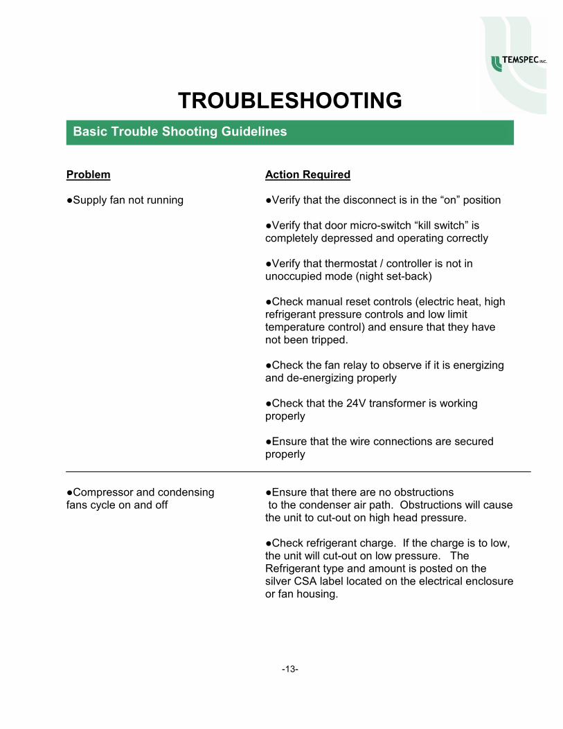
Problem Action Required ●Supply fan not running ●Verify that the disconnect is in the “on” position ●Verify that door micro-switch “kill switch” is
completely depressed and operating correctly
●Verify that thermostat / controller is not in unoccupied mode (night set-back) ●Check manual reset controls (electric heat, high refrigerant pressure controls and low limit temperature control) and ensure that they have not been tripped.
●Check the fan relay to observe if it is energizing and de-energizing properly
●Check that the 24V transformer is working
properly ●Ensure that the wire connections are secured
properly ●Compressor and condensing ●Ensure that there are no obstructions fans cycle on and off to the condenser air path. Obstructions will cause
the unit to cut-out on high head pressure. ●Check refrigerant charge. If the charge is to low, the unit will cut-out on low pressure. The Refrigerant type and amount is posted on the silver CSA label located on the electrical enclosure or fan housing.
-13-
Basic Trouble Shooting Guidelines

REPLACEMENT PARTS
TEMSPEC INCORPORATED warrants the equipment for a period of one year. This warranty covers the provision of labor to replace defective parts; defective parts to be supplied at no charge. The work is to be performed only by Temspec Inc, or it’s assigned agents. For this warranty to remain valid, the unit(s) must be maintained in accordance to the manufacturer’s recommendations. It does not cover parts damaged by vandalism, improper installation or abuse. The warranty period commences on the day that the unit is commissioned by the mechanical contractor for operation.
Contact the factory at: 1-888-TEMSPEC or (905) 670-3595 [email protected] Ask for “PART SALES”. Be sure to have the unit serial number available. It is located on the silver CSA label, on the electrical enclosure or fan housing, inside of the unit.
-14-
Limited Warranty
Part Sales