Operation & Maintenance Manual · 2900s Control Manual 3200NXT Service Manual 3214NXT Service...
37
Operation & Maintenance Manual 2900 Multi-Tank Systems - 3200NXT Part# 2900NXT OPERATION MANUAL
Transcript of Operation & Maintenance Manual · 2900s Control Manual 3200NXT Service Manual 3214NXT Service...

Operation & Maintenance Manual2900 Multi-Tank Systems - 3200NXT
Part# 2900NXT OPERATION MANUAL


Operation & Maintenance Manual2900 Multi-Tank Systems - 3200NXT
© Nelsen Corporation Part# 2900NXT OPERATION MANUAL


Table of Contents1 INTRODUCTION
2 PRINCIPLES of ION EXCHANGE 2.1 Ion Exchange Softening Process 2.2 Quality of Effluent 2.3 Capacity of Ion Exchange 2.4 Regeneration Steps
3 INSTALLATION, LOADING & START-UP PROCEDURES 3.1 Installation of Equipment 3.2 Loading of Gravel & Resin 3.3 Start-Up Procedures
4 OPERATING & REGENERATION PROCEDURES 4.1 Normal System Operations 4.2 Multi-Port Valve Operation
5 OPERATING RESPONSIBILITIES 5.1 Operator procedures 5.2 Salt Specifications
6 TROUBLE SHOOTING 6.1 General 6.2 Reduced Capacity or Poor Effluent Quality 6.3 Increase Pressure Loss or Decrease in Flow Rate
7 SOFTENER SYSTEM DRAWINGS AND SPECIFICATIONS 7.1 Typical System 5 Duplex Interlock Unit Installation 7.2 Typical System 6 Duplex Parallel Unit Installation 7.3 Typical System 7 Duplex Alternating Unit Installation 7.4 Typical System 9 Triplex Alternating Unit Installation 7.5 Typical System 14 Twin Progressive Unit Installation 7.6 Specifications 7.7 Brine Float Setting 7.8 Commercial/Industrial Brine Tanks
8 FLECK SERVICE MANUALS 2900s Control Manual 3200NXT Service Manual 3214NXT Service Manual
9 SOFTENER ADDENDUM 9.1 Sample – Water Softening Log

ForewordThe operating instructions contained herein are intended to serve as a guide for the operation of the water softener equipment.
Since it is impossible to cover all operating contingencies and emergencies in a normal operating manual, the operator should read the manual and become familiar with it contents. They should also review the flow diagrams and vendor literature. This also should include all physical details, and full knowledge of the location and function of the equipment.
The use of an operating logbook is recommended in order to provide a proper record of performance. In the event of operational problems, such a record will prove invaluable when “trouble shooting” the system. This log should include all pertinent flow rates, temperatures and water characteristics. Equipment requiring maintenance or repair should be noted so that it can be scheduled for service or repair.
Frequently, water softener equipment like other processes, develop their own distinct characteristics. Design criteria outlined in this manual is based on many years of experience. However, they do not preclude modifications due to “personality” of the system. Operators should guide themselves accordingly and make any minor adjustments necessary for proper operation of the system.
Section 1: IntroductionLong term, successful operation of any softening system depends upon the care and attention it receives. Ordinarily, water treatment systems will provide uniform performance after the initial start-up period. Total gallons between regenerations and treated water purity usually do not vary appreciably over the life of the resin as long as the incoming water does not change.
This manual in intended to be a practical reference guide for operators. In view of the fact that system performance can change very dramatically throughout the year, a discussion of “ion exchange” theory is included in addition to basic information relative to equipment operation and regeneration procedures. Thorough understanding of the simple chemical reactions will help to determine if some equipment malfunction has occurred, or if the system is simply responding to changing water conditions. For this reason, the operator and supervising personnel should review Section 2, which defines terminology and simple chemistry associated with this system.
Ion exchange (softening process) is a reversible reaction. Ion exchange softening resins have only a limited capacity for removing hardness (calcium & magnesium). If the volume of water through the resin bed exceeds its capacity, hardness leakage will be detected in the effluent water. Therefore, service runs must be terminated before hardness leakage occurs. When the service run is completed, the resin is treated with sodium chloride (NaCl) to displace the hardness and restore its capacity. This process is termed “regeneration”.
How completely softening can be accomplished depends upon several factors. The primary influences are the incoming water, type of resin, and amount of salt. Equally important, secondary influences are the concentrations and flow rates at which NaCl is introduced.

Section 2: Principles Of Ion Exchange2.1 Ion Exchange Softening ProcessIn order to understand the softening process of ion exchange, it is first necessary to understand the meaning of the terms which are used in the explanation. Hard Water, Cation Exchanger, and Brine are defined below and used to show how the ion exchange process works.
Hard Water – All natural water contains dissolved impurities, but in widely varying amounts. There is always a balance of cations (+) and anions(-), but in the softening process anions have no effect. Water will be hard if it contains large amounts of calcium (Ca++) and/or magnesium (Mg++) ions.
Brine – Salt which has dissolved in water. Completed brine (100%) saturation contains as much salt as possible in water solution (26% to 27%). Salt – Sodium chloride (NaCl), when dissolved in water splits up (ionizes) into sodium (Na+) ions and chloride (Cl-) ions.
Saturated Brine – Contains a large amount of Na+ and Cl- ions (concentration is over 200,000 ppm). When used to regenerate a cation exchanger, only the sodium (Na+) ions are used. The chloride (Cl-) ions are washed to drain.
Cation Exchanger – A high-capacity bead form polystyrene sulfonate cation resin. These beads have negative (-) electric charge, which attracts and holds the cations, which are positively (+) charged (works like a magnet).
Softening Process – When the bead reaches the exchange capacity of Ca++ or Mg++ hardness break through the resin bed will increase. The increase in effluent hardness will indicate that the effective capacity of the cation resin has been reached. The cation exchanger must be regenerated to restore it to its original capacity.
Regeneration – Brine is used to regenerate the cation exchanger to its original capacity. Sodium (Na) ions attach to the resin beads forcing the calcium and magnesium ions to release from the resin beads. Once the exchange has taken place the sodium ions are rinsed to drain. The softener in now ready to remove hardness from the water.

2.2 Quality Of Effluent If the hard water contains less than 500 ppm (about 30 grains) of calcium, magnesium and sodium salts, all expressed as CaCO3, it will be found that the effluent from a softener will contain an average of not more that 2 ppm actual total hardness (zero hardness by the soap test). However, as the total cation concentration in the hard water increases above 500 ppm, the average hardness in the effluent will also increase proportionately
The reason for this is that when the sodium salt - those present in the raw water plus those formed by the exchange reactions - are present in high enough concentrations, they cause a “back-regeneration” effect at the same time as the softening process is taking place. This effect prevents as complete a removal of calcium and magnesium as would otherwise be possible.
It is often possible to reduce the average hardness in the effluent below normally expected concentrations, by using a greater amount of salt than usual for regeneration. Normal Softening Cycle - At the start of a normal softening cycle, the hardness in the effluent drops rapidly as the residue of hardness ions left in the bed at the end of the rinse are forced out. The effluent hardness reaches a certain minimum value and remains at approximately this concentration for the major part of the softening run.
2.3 Capacity Of Ion ExchangerThe capacity for the removal of calcium and magnesium depends mainly upon the type of ion exchanger which is used. It is further influenced by the amounts of hardness and sodium ions in the raw water, and by the amount of salt used for regeneration.
Raw Water - The effect of the amounts of hardness and sodium ions in the raw water, is expressed in terms of compensated hardness. The hardness of the raw water is considered to be greater than it actually is for capacity determinations, whenever: (a) the total hardness is greater than 400 ppm (as CaCO3), or (b) the sodium salts are over 100 ppm as (CaCO3). This “greater-than-actual” hardness is referred to as compensated hardness.
Salt Dosage - The capacity, which will be obtained from a cation exchanger, is also determined by the amount of salt used during regeneration. The grains of hardness, which can be removed by each cubic foot of ion exchange, resin increases as more salt is used for regeneration.
At the same time, the efficiency of salt usage decreases with the higher regenerant dosages. That is, a greater number of grains of hardness are removed for each pound of salt used at the lower salt dosages, (and consequently, at the lower capacities). Thus, greater economy may be obtained at the expense of the number of gallons of water softened between regenerations.

Calculation Of Capacity - To determine the capacity of any cation exchanger, follow the procedure outlined below:
From the analysis of the raw water, determine the actual total hardness as the sum of the calcium and magnesium concentrations expressed as CaCO3. If necessary, calculate the compensated hardness in accordance with the formula given above.
Express parts per million (ppm) of total hardness as grains per gallon by means of the following conversion formula:
PPM / 17.1= grains per gallon (gpg)
2.4 Regeneration Steps
Regeneration is a process by which ions are stripped from the exhausted resin bed and its ion removal ability is restored. All exchangers, ranging from a simple water softener to a complex mixed bed deionizer go through four basic regeneration steps. There may be variations in flow rates; types of regenerating chemicals and regenerant concentrations but these general steps are as follows:
Backwash - Water flow is reversed so that it passes upward through the resin bed. Flow rates are sufficiently high to expand (fluidize) and to agitate the bed without washing large resin particles out of the tank. This action relieves any compaction that may have occurred during the service run. In addition, very fine resin fragments that can form during normal service are washed to drain. Proper backwash is essential to good exchanger performance. A compacted bed can develop high-pressure losses during service, which, in turn, can lead to flow channeling problems.
Brine In - A brine solution is passed slowly through the resin, displacing the exchanged ions and discharging them to drain. Proper control of flow rate and brine concentration is important to insure high regeneration efficiency. The amount of salt that is used depends upon the allowable hardness leakage for any given water supply and the desired resin operating capacity.
Displacement Rinse (Slow Rinse) - After all of the brine has been introduced into the resin bed, water continues to flow at approximately the same low flow rate. This slowly displaces the salt from the free space above the bed and from the void volume between resin particles, insuring that it is utilized to maximum efficiency.
Final Rinse - The final step in regenerating is important in that it will displace any salt left in the exchanger vessel prior to returning to service.

Section 3: Installation, Loading & Start Up Procedures
3.1 Installation of Equipment 1. Before beginning installation, review the following instructions to familiarize yourself
with the general placement of the equipment.
2. The operating pressure is between 30 to 100 psi. If pressure is higher than 100 psi, then a pressure regulator must be installed.
3. The operating temperature is between 35 to 100 degrees F.
4. Locate the equipment in the specified location. When setting the equipment, install on level concrete pad if possible. Level equipment as required.
5. Equipment should be located near a floor drain. The floor drain should be adequate in size to handle the softener backwash flow rate.
6. Interconnecting piping and shut off valves of equipment should be installed per local plumbing codes by a certified plumber.
7. Unions to be installed in the drain line for cleaning of the backwash flow control. Do NOT reduce the drain line pipe size, or install a manual shut off valve. Provide an air gap in the drain line in accordance with local plumbing codes.
8. Before installing any flow meters, read the instruction manual on proper installation of the sensor. Many flow meters must be installed in a certain way to operate properly.
9. Once installed close all manual shut off valves.
10. Brine tank should be located near the softeners, installed on a smooth flat surface. If not the brine tank should be placed on a smooth piece of exterior plywood and level.
11. Once the brine tank has been set in place, remove the lid and check that the brine well is in a vertical position. If the brine tank is equipped with a brine valve/float assembly, remove and check to make sure the brine float setting is correct (See Section 7 – Brine Float Setting). The float will have a certain setting depending on the amount of salt used per regeneration. If incorrect adjust float to proper setting.
12. Place brine valve into brine well and set all the way to the bottom of the brine tank.
13. Fill brine tank with approximately 13-19 inches of water. The water level should be approximately half to the height of float setting.

3.2 Loading Gravel & Resin 1. Before loading the gravel, check the lower
distributor for possible damage from shipping. Making sure all laterals are in proper location. Do NOT proceed with loading if any damage is evident.
2. Once the distributor is checked out ok, plug the end of the distributor tube with a PVC cap/plug, clean rag or tape to keep the gravel and resin out of the center of the riser.
3. Fill the tank with approximately 1/4 -1/3 full of water. The water will act as a buffer when loading the gravel and prevent any damage to the lower distributor.
4. Determine the amount of gravel and resin required for each tank. When coarse, medium and fine gravels are specified, add in that order. Slowly pour the gravel into the tank. Try to keep it as level as possible.
(Not all systems have multiple sizes of gravel)
5. Once the gravel has been loaded. Slowly pour the determined amount of resin into the tank. Try to keep it as level as possible.
6. Flush the tank opening with water to clean resin beads from the top of the tank. Then, remove the cap, plug, rag or tape from the distributor pipe. Apply a light coat of approved lubricating silicone to the top edge of the pipe. (DO NOT USE PETROLIUM LUBRICANTS, ie. Vaseline)
7. Finish filling the tank with water, up to the top. This will eliminate air space and prevent excessive air – head pressure when the water conditioner is pressurized.
8. Once completed, lubircate the o-ring and carefully install the control valve being careful not to cross thread the valve into the tank, do not overtighten.
9. Keep power off until final checkout procedure is completed.
1
4
5
3
2
6

3.3 Start-Up Procedures 1. Once the piping and installation completed, and with the mineral in the tank, proceed
with the following.
2. Open the manual by-pass valve. The manual inlet and outlet valves are to remain closed.
3. Plug electrical power of the main controller to a wall outlet (120v)
4. The main controller is either a Fleck 3200 NXT or Fleck 3214 NXT. The controller is now ready to be programmed. See Section 8. Familiarize yourself with the proper manual, on proper wiring and programming procedure for your specific controller.
5. Once the programming is completed, manually set the valve unit into backwash. Slowly open the manual inlet valve. DO NOT OPEN INLET VALVE COMPLETELY. (Full flow of water could cause loss of resin) Water will enter in the bottom of the mineral tank, causing any air to expel from top to the drain. Continue to slowly fill until all the air has expelled from the tank and only water flows to drain.
6. When only water flows to drain, open manual inlet valve completely and continue backwashing until water is clear from any color.
7. Manually set the unit through regeneration one step at a time. When doing this make sure the piston completely comes to a stop before proceeding to the next step.
8. Fill brine tank with proper amount and type of salt recommended.
9. Close the manual by-pass valve and open manual outlet valves. The system is ready for service.

Section 4: Operating & Regeneration Procedures
4.1 Normal System OperationThe system is designed for fully automatic operation. Service runs will automatically terminate when an exhaustion end-point is reached.
Although it should not be absolutely necessary to observe every regeneration, Operators should periodically witness a complete cycle to make sure that critical flow rates and steps have not gotten out of adjustment.
Daily Date and Time
Meter Reading Outlet Hardness Inlet Hardness Inlet and outlet pressure gauge readings; calculated pressure drop Record Salt Usage
Miscellaneous
All of this information can be invaluable in detecting if something is going wrong, or when trouble shooting. High-pressure drop during the run can be symptomatic of buildup of suspended solids on the bed or excess breakage of resin beads. Short runs or higher than normal effluent hardness could be caused by resin fouling. This could be caused by malfunction during regeneration or even a contaminated batch of salt.

4.2 Multi-Port Valve Operation (See Section 8 – Fleck 2900s Control Manual)
Multi-port valve consist of Fleck 2900s multi-port double piston operated valve. The valve operates with upper and lower piston that moves on a seals and spacer assembly. The upper piston is for regeneration and the lower piston is for service. The piston moves to a certain location, which determines the operation position of the unit.
SERVICE
During service flow, raw water passes through the valve and downflow through the softener up through the distributor tube to service. Service flow continues until the water meter/counter has signaled an end of run and will automatically switch service flow to the other unit and go into regeneration.
REGENERATION
Based on 10 grains/gallon of hardness as CaCO3, approximately 3000 gallons of water per cubic foot of resin in the softener can flow before exhaustion of resin.
BACKWASH
Raw water flow is diverted to pass down through the distributor tube and up-flow through the softener. The water expands the bed scrubbing the resin beads and washing any entrapped dirt out to drain. Backwash sequence lasts approximately 15 minutes.
BRINE AND SLOW RINSE
Raw water is directed through the ejector located at the multi-port valve creating a venturi action in the ejector to draw the required amount of brine into the softener. The brine float air check valve shuts off the brine flow when the preset draw down is reached. Raw water continues to the drain slow rinsing the resin for the remainder of the cycle. Brine and slow rinse sequence generally lasts 60 minutes.
FAST RINSE
Raw water passes through the multi-port valve down flow through the softener and out to drain. This sequence removes all remaining brine from the resin and lasts 10 minutes. When the regeneration cycle is completed and the softener goes back into service, raw water will backflow through the ejector refilling the brine tank to its normal level. The brine valve float will control water makeup level.
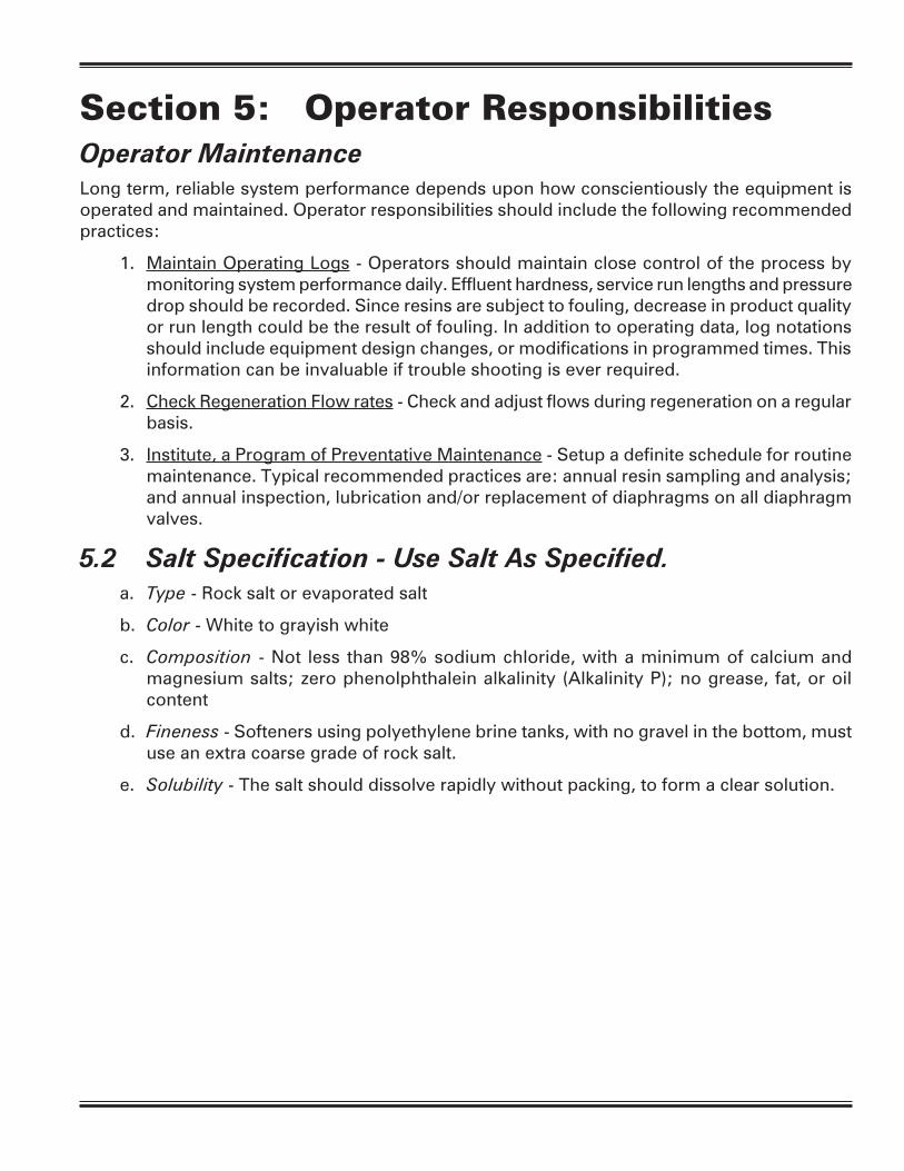
Section 5: Operator ResponsibilitiesOperator MaintenanceLong term, reliable system performance depends upon how conscientiously the equipment is operated and maintained. Operator responsibilities should include the following recommended practices:
1. Maintain Operating Logs - Operators should maintain close control of the process by monitoring system performance daily. Effluent hardness, service run lengths and pressure drop should be recorded. Since resins are subject to fouling, decrease in product quality or run length could be the result of fouling. In addition to operating data, log notations should include equipment design changes, or modifications in programmed times. This information can be invaluable if trouble shooting is ever required.
2. Check Regeneration Flow rates - Check and adjust flows during regeneration on a regular basis.
3. Institute, a Program of Preventative Maintenance - Setup a definite schedule for routine maintenance. Typical recommended practices are: annual resin sampling and analysis; and annual inspection, lubrication and/or replacement of diaphragms on all diaphragm valves.
5.2 Salt Specification - Use Salt As Specified. a. Type - Rock salt or evaporated salt
b. Color - White to grayish white
c. Composition - Not less than 98% sodium chloride, with a minimum of calcium and magnesium salts; zero phenolphthalein alkalinity (Alkalinity P); no grease, fat, or oil content
d. Fineness - Softeners using polyethylene brine tanks, with no gravel in the bottom, must use an extra coarse grade of rock salt.
e. Solubility - The salt should dissolve rapidly without packing, to form a clear solution.

Section 6: Trouble Shooting6.1 GeneralThe most common system failures are either “poor water quality” or “short service” run. If the change in performance occurs suddenly — i.e., within a couple of operating cycles, 9 times out of 10 these problems result from:
a Insufficient regenerating chemical quantity,
b Poor control of chemical concentrations and/or flow rates,
c Over-running (over exhausted) resin beds during a service run
d Flow channeling because of a plugged or failed internal flow distributor.
If however, the change occurs gradually over a period of weeks or months, the problem is more likely due either to a change in feed water mineral content or from fouling of the resins. Under any circumstance, the importance of maintaining Operating Logs cannot be stressed too strongly. Study of the Log will often reveal any trend that might be developing. In the case of fouling, periodic resin analyses are the only way to identify such problems.
General guidelines that wilt assist in determining common operating difficulties are given below. Often poor performance results because of one or more contributing factors. The recommended approach is to go systematically through the list to see what symptoms apply and then to take corrective action.
6.2 Reduced Capacity Or Poor Effluent Quality SOURCE OF TROUBLE POSSIBLE CAUSE CORRECTIVE ACTION
Change In Chemical Higher hardness Check hardness by Composition Of in raw water chemical test. If it has Raw Water changed, compute new capacity and use new meter setting
Softener Being Raw water has Check raw water hardness Overrun Consistently more hardness and meter setting. Give unit a “double regeneration
Meter setting is incorrect Reset meter per manual
Incorrect Chemical Test procedure in error Follow instructions carefully Test Results
Chemicals for test Replace weak or causing error contaminated test solutions
Meter Slippage Worn or damaged meter Replace or repair as necessary
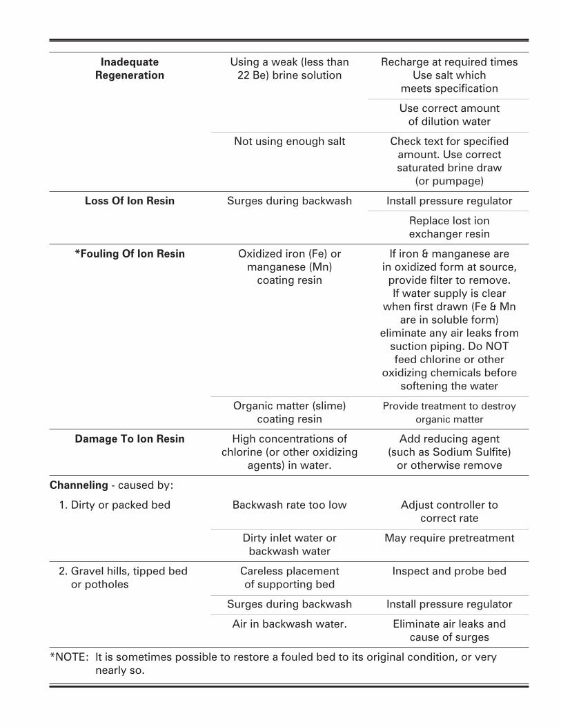
Inadequate Using a weak (less than Recharge at required times Regeneration 22 Be) brine solution Use salt which meets specification
Use correct amount of dilution water
Not using enough salt Check text for specified amount. Use correct saturated brine draw (or pumpage)
Loss Of Ion Resin Surges during backwash Install pressure regulator
Replace lost ion exchanger resin
*Fouling Of Ion Resin Oxidized iron (Fe) or If iron & manganese are manganese (Mn) in oxidized form at source, coating resin provide filter to remove. If water supply is clear when first drawn (Fe & Mn are in soluble form) eliminate any air leaks from suction piping. Do NOT feed chlorine or other oxidizing chemicals before softening the water
Organic matter (slime) Provide treatment to destroy coating resin organic matter
Damage To Ion Resin High concentrations of Add reducing agent chlorine (or other oxidizing (such as Sodium Sulfite) agents) in water. or otherwise remove
Channeling - caused by:
1. Dirty or packed bed Backwash rate too low Adjust controller to correct rate
Dirty inlet water or May require pretreatment backwash water
2. Gravel hills, tipped bed Careless placement Inspect and probe bed or potholes of supporting bed
Surges during backwash Install pressure regulator
Air in backwash water. Eliminate air leaks and cause of surges
*NOTE: It is sometimes possible to restore a fouled bed to its original condition, or very nearly so.

6.3 Increase Pressure Lose Or Decrease In Flow RateDirty Or Packed Bed - See above for possible causes and corrective actions.
Restricted Flow – Obstruction in meter, piping or valves. Inspect and clean as required.

Sect
ion 7
: S
oft
ener
Syst
em
Dra
win
gs
& S
peci
fica
tions
7.1
Typ
ical
Sys
tem
5 D
up
lex
Inte
rloc
k U
nit
Inst
alla
tion
VACU
UM
BRE
AKE
R(R
ECO
MM
END
ED)
VACU
UM
BRE
AKE
R(R
ECO
MM
END
ED)
INLE
TO
UTL
ET
MET
ER
MET
ER SO
FTEN
ERBR
INE
TAN
KBR
INE
TAN
KU
NIT
AU
NIT
B
DRA
IN


7.2
Typ
ical
Sys
tem
6 D
up
lex
Par
alle
l Un
it In
stal
lati
on

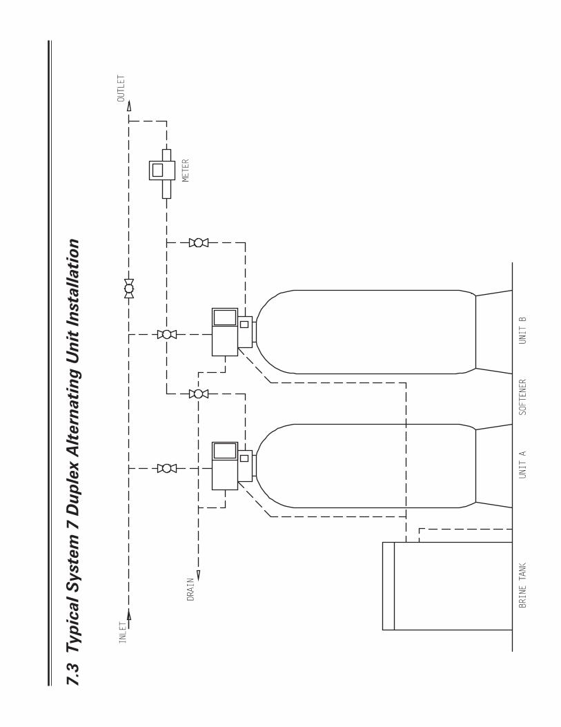
7.3
Typ
ical
Sys
tem
7 D
up
lex
Alt
ern
atin
g U
nit
Inst
alla
tion

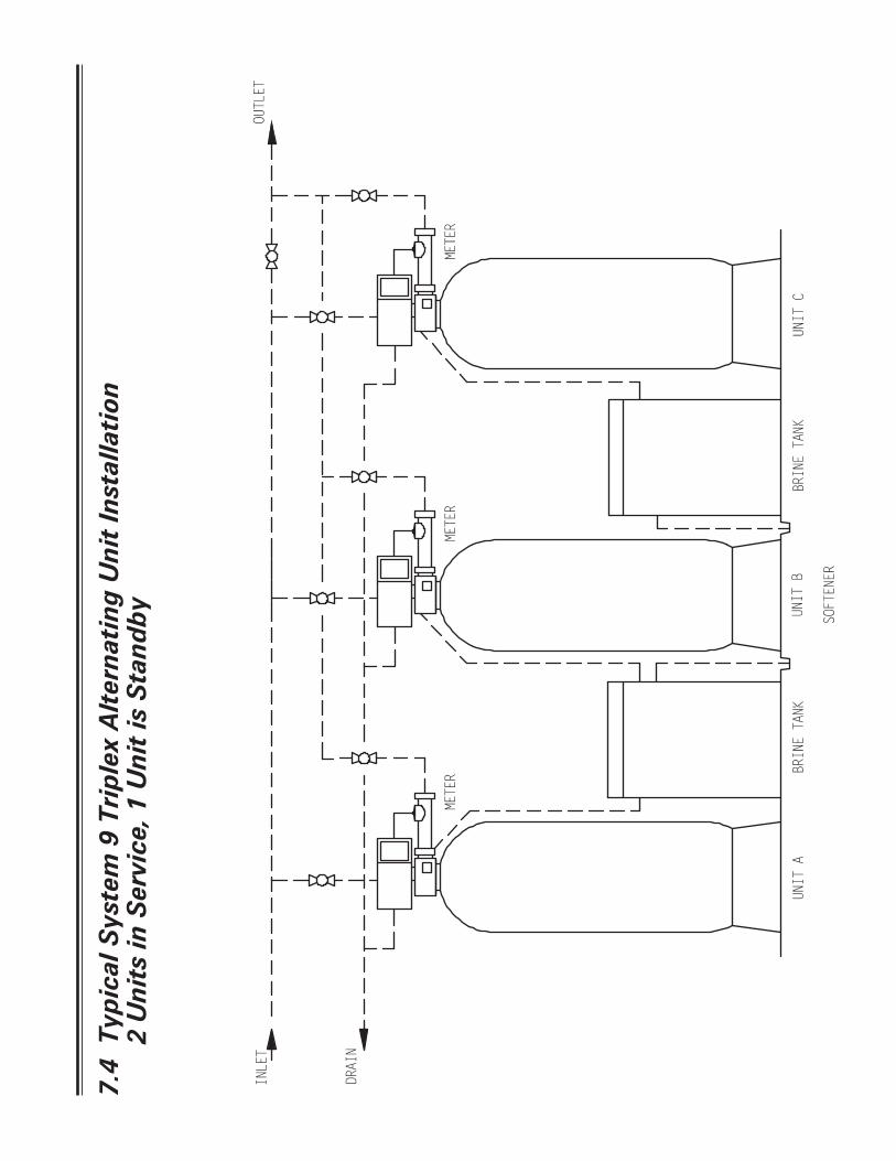
7.4
Typ
ical
Sys
tem
9 T
rip
lex
Alt
ern
atin
g U
nit
Inst
alla
tion
2
Un
its
in S
ervi
ce, 1
Un
it is
Sta
nd
by

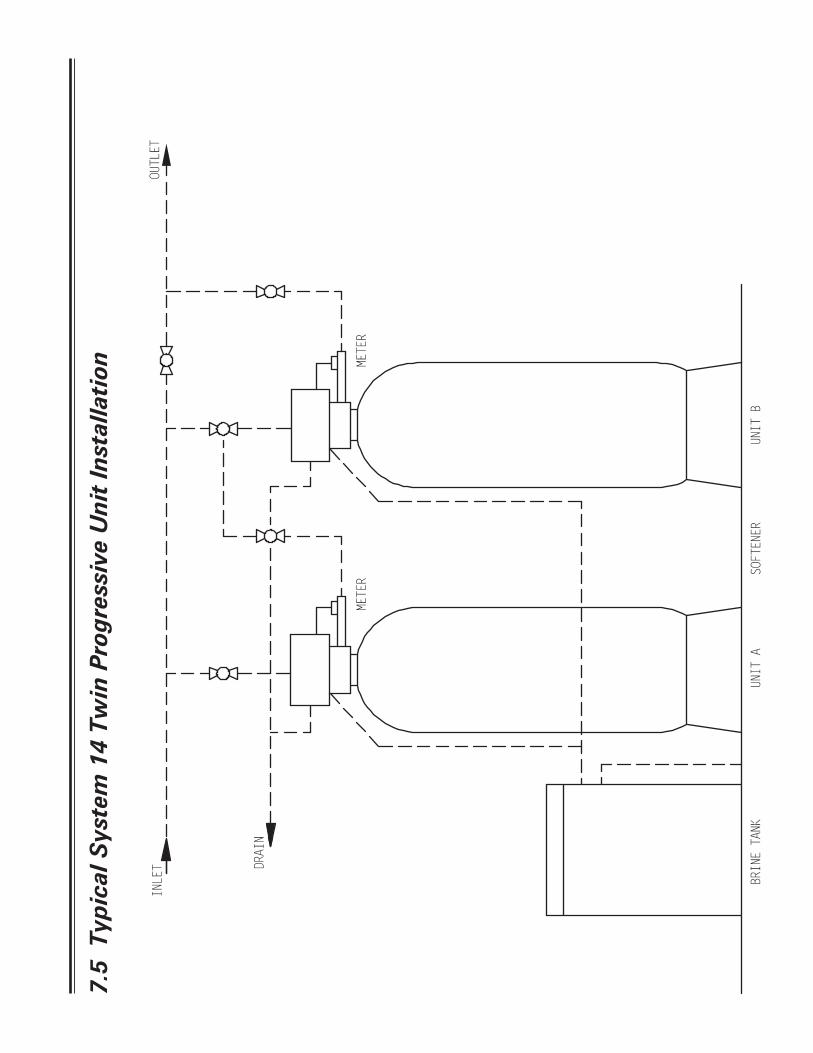
7.5
Typ
ical
Sys
tem
14
Twin
Pro
gres
sive
Un
it In
stal
lati
on

7.6 Specifications
SpecificationsModel 120,000 150,000 210,000 300,000 450,000 600,000Capacity (1) 120,000 150,000 210,000 300,000 450,000 600,000Capacity (2) 96,000 120,000 168,000 240,000 360,000 480,000Media Tank Size 16" x 65" 18" x 65" 21" x 62" 24" x 72" 30" x 72" 36" x 72"Resin, Cubic Feet 4 5 7 10 15 20Resin, Pounds 200 # 250 # 350 # 500 # 750 # 1000 #Gravel Underbed, 1/4" x 1/8" 75 # 100 # 50 # 100 # 100 # 150 #Gravel Underbed, 1/2" x 1/4" n/a n/a 100 # 150 # 250 # 350 #Max Service Flow Rate, GPM (3) 57 62 77 95 140 140Min Service Flow Rate, GPM 40 50 55 60 75 100Backwash Flow Rate, GPM 7 9 12 15 25 35Backwash, Minutes 10 10 10 10 10 10Backwash, Pins 5 5 5 5 5 5Brine Draw and Rinse, Minutes 60 60 60 60 60 60Brine Draw and Rinse, Holes 30 30 30 30 30 30Rapid Rinse, Minutes 10 10 10 10 10 10Rapid Rinse, Pins 5 5 5 5 5 5Salt Required (1) 60 # 75 # 105 # 150 # 225 # 300 #Salt Required (2) 40 # 50 # 70 # 90 # 135 # 180 #Refill Time, Minutes (1) 16 18 18 26 16 18Refill Time, Holes (1) 8 9 9 13 8 9Refill Time, Minutes (2) 12 12 12 16 10 14Refill Time, Holes (2) 6 6 6 8 5 7Return To Service, Minutes 4 4 4 4 4 4Return To Service, Pins 2 2 2 2 2 2Brine Line Flow Control, GPM 1.2 1.5 2 2 5 5Injector Size # 3 # 3 # 4 # 4 # 5 # 6Injector Color Yellow Yellow Green Green n/a n/a Notes: (1) - At 15 Pounds Per Cubic Foot yields 30,000 Grains Capacity Per Cubic Foot. (2) - At 9 Pounds Per Cubic Foot yields 24,000 Grains Capacity Per Cubic Foot. (3) - At 15 PSI Pressure Drop. 2" Meter Range Standard Range, 2" - 21,250 Gallons Extended Range, 2" - 106,250 Gallons

7.7 Brine Float Settings
Notes:1 - Brine Valve Clack 454 Hi-Flow – 3/4" connection2 - Salt deck height as noted.3 - Float setting from bottom of brine tank.
Tank Size Cu. Ft. Brine Tank Brine Valve1 Salt Deck2 Brine valve set at3
Yes NO 9lb/cf. 15lb/cf.
16 x 65 4 24 x 41 454-HF 6" 10" 18"
X 16" 24"
18 x 65 5 24 x 41 454-HF 6" 14" 24"
X 20" 30"
21 x 62 7 24 x 41 9" 19" 33"
24 x 50 454-HF
X 28" —
24 x 72 10 30 x 48 454-HF 9" 17" 29"
X 25" 38"
30 x 48 454-HF 9" 26" 44"
30 x 72
15
X 38" —
39 x 48 454-HF 9" 14" 25"
X 23" 34"
39 x 48 454-HF 12" 18" 39"
36 x 72 20 X 30" —
42 x 60 454-HF
9" 17" 30" X 26" 39"
50 x 60 454-HF 12" 29" —
48 x 72 40
X 37" —
60 x 60 454-HF 12" — 26"
X 26" 38"

454 3⁄4" HIGH FLOW BRINE VALVE — Today's larger commercial brine valves demand higher brine draw and refill rates. Building upon the original 454's design, the 454 3⁄4" High Flow has improved flow characteristics allowing brine draw up to 10 gallons per minute and refill rates up to four gallons per minute. A flow diffuser and heavier float reduces the potential of premature checking. 36" and 54" Float Rods are available. Please specify length as listed below:H7070-36HF - 454 3⁄4" High Flow Brine Valve (36" Rod)H7070-54HF - 454 3⁄4" High Flow Brine Valve (54" Rod)
454 3⁄4" High FlowBrine Valve
H7070-02
H7070-01
H7070-03BH7070-18
H7070-04HF
H7070-05
H7070-08-36C orH7070-08-54C
H7070-16
H7070-06
3⁄4" Brine Tube(Not Supplied)
H7070-17
H7070-04*(Optional)
H7070-19
H7070-14
H7070-13HF
H7070-12HF(3 Required)
H7070-11(6 Required)
H7070-10(6 Required)
H7070-03T
H7070-07
ORDER NUMBERS:H7070-10 SS Lock WasherH7070-11 SS NutH7070-12HF High Flow Float GrommetH7070-13HF High Flow FloatH7070-14 Float Rod Guide AsyH7070-16 Upper Seat RetainerH7070-17 Refill ChamberH7070-18 Lower Seat RetainerH7070-19 O-ring Refill Chamber SealH7070-26HF Basket DiffuserH7070-27HF Retainer RingH7070-28HF SS HF Screw
H7070-01 BodyH7070-02 Plastic Plug-3⁄4"H7070-03T Seat Washer Top (Orange)H7070-03B Seat Washer Bottom (Clear)H7070-04HF High Flow Air Check BallH7070-04* Refill Check BallH7070-05 Ball CageH7070-06 O-ring Cover SealH7070-07 Body CoverH7070-08-36C Float Rod and Seat Cone Asy - 36"H7070-08-54C Float Rod and Seat Cone Asy - 54"
0
1
2
3
4
0 0.5 1 1.5 2Pressure Drop (psig)
Re
fill
Flo
w R
ate
(g
pm
)
H7070-28HF(6 required)
H7070-27HF
H7070-26HF
Quantity 2 - one above and one below float
* Optional for control valves without timed refill. See note on back of page for further information.
NOTE: The 454 3⁄4" High Flow Brine Valve isdesigned for salt brine only. It will also fit inside a brine well that is 5" or larger.
0
2
4
6
8
10
0 2 4 6 8 10
Brine Draw Rate (gpm)
Va
cc
uu
m (
In.
of
Hg
) Brine Draw Rate
Brine Draw Rate (gpm)
Vacc
uum
(In.
of H
g)
Refill Flow Rate
Pressure Drop (psig)
Refil
l Flo
w R
ate
(gpm
)
454 3⁄4" HIGH FLOW BRINE VALVE — Today's larger commercial brine valves demand higher brine draw and refill rates. Building upon the original 454's design, the 454 3⁄4" High Flow has improved flow characteristics allowing brine draw up to 10 gallons per minute and refill rates up to four gallons per minute. A flow diffuser and heavier float reduces the potential of premature checking. 36" and 54" Float Rods are available. Please specify length as listed below:H7070-36HF - 454 3⁄4" High Flow Brine Valve (36" Rod)H7070-54HF - 454 3⁄4" High Flow Brine Valve (54" Rod)
454 3⁄4" High FlowBrine Valve
H7070-02
H7070-01
H7070-03BH7070-18
H7070-04HF
H7070-05
H7070-08-36C orH7070-08-54C
H7070-16
H7070-06
3⁄4" Brine Tube(Not Supplied)
H7070-17
H7070-04*(Optional)
H7070-19
H7070-14
H7070-13HF
H7070-12HF(3 Required)
H7070-11(6 Required)
H7070-10(6 Required)
H7070-03T
H7070-07
ORDER NUMBERS:H7070-10 SS Lock WasherH7070-11 SS NutH7070-12HF High Flow Float GrommetH7070-13HF High Flow FloatH7070-14 Float Rod Guide AsyH7070-16 Upper Seat RetainerH7070-17 Refill ChamberH7070-18 Lower Seat RetainerH7070-19 O-ring Refill Chamber SealH7070-26HF Basket DiffuserH7070-27HF Retainer RingH7070-28HF SS HF Screw
H7070-01 BodyH7070-02 Plastic Plug-3⁄4"H7070-03T Seat Washer Top (Orange)H7070-03B Seat Washer Bottom (Clear)H7070-04HF High Flow Air Check BallH7070-04* Refill Check BallH7070-05 Ball CageH7070-06 O-ring Cover SealH7070-07 Body CoverH7070-08-36C Float Rod and Seat Cone Asy - 36"H7070-08-54C Float Rod and Seat Cone Asy - 54"
0
1
2
3
4
0 0.5 1 1.5 2Pressure Drop (psig)
Re
fill
Flo
w R
ate
(g
pm
)
H7070-28HF(6 required)
H7070-27HF
H7070-26HF
Quantity 2 - one above and one below float
* Optional for control valves without timed refill. See note on back of page for further information.
NOTE: The 454 3⁄4" High Flow Brine Valve isdesigned for salt brine only. It will also fit inside a brine well that is 5" or larger.
0
2
4
6
8
10
0 2 4 6 8 10
Brine Draw Rate (gpm)
Va
cc
uu
m (
In.
of
Hg
) Brine Draw Rate
Brine Draw Rate (gpm)
Vacc
uum
(In.
of H
g)
Refill Flow Rate
Pressure Drop (psig)
Refil
l Flo
w R
ate
(gpm
)454 3/4" High Flow Brine Valve
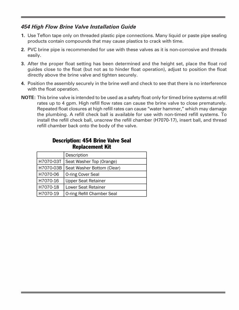
454 High Flow Brine Valve Installation Guide
1. Use Teflon tape only on threaded plastic pipe connections. Many liquid or paste pipe sealing products contain compounds that may cause plastics to crack with time.
2. PVC brine pipe is recommended for use with these valves as it is non-corrosive and threads easily.
3. After the proper float setting has been determined and the height set, place the float rod guides close to the float (but not as to hinder float operation), adjust to position the float directly above the brine valve and tighten securely.
4. Position the assembly securely in the brine well and check to see that there is no interference with the float operation.
NOTE: This brine valve is intended to be used as a safety float only for timed brine systems at refill rates up to 4 gpm. High refill flow rates can cause the brine valve to close prematurely. Repeated float closures at high refill rates can cause “water hammer,” which may damage the plumbing. A refill check ball is available for use with non-timed refill systems. To install the refill check ball, unscrew the refill chamber (H7070-17), insert ball, and thread refill chamber back onto the body of the valve.
1. Use Teflon tape only on threaded plastic pipe connections. Many liquid or paste pipe sealing products contain compounds that may cause plastics to crack with time.
2. PVC brine pipe is recommended for use with these valves as it is non-corrosive and threads easily.
3. After the proper float setting has been determined and the height set, place the float rod guides close to the float (but not as to hinder float operation), adjust to position the float directly above the brine valve and tighten securely.
4. Position the assembly securely in the brine well and check to see that there is no interference with the float operation.
NOTE: This brine valve is intended to be used as a safety float only for timed brine systems at refill rates up to 4 gpm. High refill flow rates can cause the brine valve to close prematurely. Repeated float closures at high refill rates can cause "water hammer," which may damage the plumbing. A refill check ball is available for use with non-timed refill systems. To install the refill check ball, unscrew the refill chamber (H7070-17), insert ball, and thread refill chamber back onto the body of the valve.
454 3⁄4" High Flow Brine Valve Installation Guide
Part No.: H7070-24Updated 11/03
4462 DURAFORM LANE • WINDSOR, WISCONSIN 53598-9716 USAPHONE (608) 846-3010 FAX (608) 846-2586 SALES/CUSTOMER SERVICE FAX (800) 755-3010
www.clackcorp.com
DescriptionH7070-03T Seat Washer Top (Orange)H7070-03B Seat Washer Bottom (Clear)H7070-06 O-ring Cover SealH7070-16 Upper Seat RetainerH7070-18 Lower Seat RetainerH7070-19 O-ring Refill Chamber Seal
Order No: H7070-34Description: 454 Brine Valve Seal
Replacement Kit
Commercial/IndustrialRotationally Molded Brine Tanks
EZISKNAT REBMUNREDRO RETEMAID THGIEH YTICAPACTLAS EMULOV THGIEW84x42 00P1BC84422G "42 "84 .sbl008 .lag59 .sbl0306x42 00P1BC06422G "42 "06 .sbl0001 .lag511 .sbl2384x03 00P1BC84032G "03 "84 .sbl0021 .lag541 .sbl8406x03 00P1BC06032G "03 "06 .sbl0061 .lag081 .sbl6584x93 00P1BC84932G "93 "84 .sbl0022 .lag052 .sbl7606x93 00P1BC06932G "93 "06 .sbl0072 .lag003 .sbl0806x24 00P1BC06242G "24 "06 .sbl0013 .lag053 .sbl4806x05 00P1BC06052G "05 "06 .sbl0054 .lag005 .sbl701
Commercial and industrial water softeners require a large volume of brine during each regeneration. From a capacity of 95 gallons to 500 gallons, our Rotationally Molded Brine Tanks are built to last. Molded out of durable, chemically resistant high density polyethylene, their 1/4" seamless walls won't bulge. All tanks and covers are black. Rotationally Molded Brine Tanks are strong enough to handle your toughest brine requirements.
Also available:
24" Plastic Grids
30" Plastic GridsPlease consult factory for order numbers.
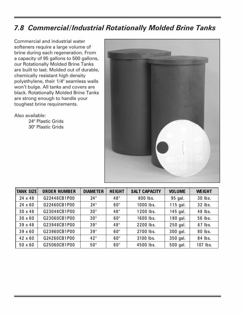
7.8 Commercial/Industrial Rotationally Molded Brine Tanks
Commercial and industrial water softeners require a large volume of brine during each regeneration. From a capacity of 95 gallons to 500 gallons, our Rotationally Molded Brine Tanks are built to last. Molded out of durable, chemically resistant high density polyethylene, their 1/4" seamless walls won’t bulge. All tanks and covers are black. Rotationally Molded Brine Tanks are strong enough to handle your toughest brine requirements.
Also available: 24" Plastic Grids 30" Plastic Grids

Section 8: 2900 Control Manual 3200 NXT Manual

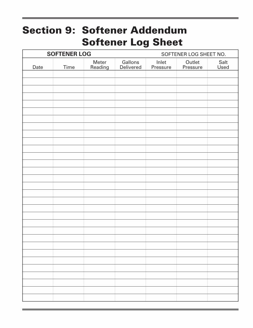
SOFTENER LOG SOFTENER LOG SHEET NO.
Meter Gallons Inlet Outlet Salt Date Time Reading Delivered Pressure Pressure Used
Section 9: Softener Addendum Softener Log Sheet