Operation CVHE-M-7 Maintenance - Surplus...
131
T M Operation Maintenance Library P rod uct Section Product Model Literature Type Sequence Date File No . Supersedes Water - Cooled , Hermetic CenTraVac O Models CVHE and CVHF 50 and 60 Hz Cooling -Only and Heat - Recovery , Direct-Drive CenTraVacs with UCP2 Control Panels CVHE 230 thru CVHE - 890 , 1120 , 1250 "1W" Design Sequences CVHF 650 , 770 , 910 1060 , 1280 "E0" Design Sequence CVHE - M - 7 Service Literature Refrigeration Centrifugal Liq. Chiller, Water-Cooled 50/60 HZ CVHE, CVHF(Cooling-Only & Heat Recovery) Operation/Maintenance 7 February 1, 1994 S V-R F-C N-CV H E-M-7-2194 • ^ X39470739 -01 Since the Trane Company has a policy of continuous product improvement, it rese rves the ri g ht to cha ng e specifica - tion s a nd des ig n without n otic e . The in sta ll ationan d serv icin gof the equi p men t refe rred to in this bookl d shoul d be d on e by qu al ifi ed, ex pe rie nc ed te c hn i cia n s .
-
Upload
trannguyet -
Category
Documents
-
view
229 -
download
0
Transcript of Operation CVHE-M-7 Maintenance - Surplus...
TM
OperationMaintenance
Library
Product Section
Product
Model
Literature Type
Sequence
Date
File No .
Supersedes
Water-Cooled ,HermeticCenTraVacO
Models CVHE and CVHF50 and 60 Hz
Cooling-Only and Heat-Recovery ,Direct-Drive CenTraVacs with UCP2Control Panels
CVHE 230 thru CVHE -890 , 1120 , 1250
"1W" Design Sequences
CVHF 650, 770 , 9101060 , 1280
"E0" Design Sequence
CVHE-M -7
Service Literature
Refrigeration
Centrifugal Liq. Chiller, Water-Cooled
50/60 HZ CVHE, CVHF(Cooling-Only & Heat Recovery)
Operation/Maintenance
7
February 1, 1994
SV-RF-CN-CVHE-M-7-2194
• ^
X39470739-01
Since the Trane Company has a policy of continuous product improvement, it reserves the ri g ht to change specifica -tion s a nd des ig n without notic e . The in sta ll ation an d serv icing of the equi pmen t refe rred to in this book ld should bedone by qu a l if i ed , ex pe rie nced te chn i cia n s .

I N DEX OF REPORT GROUPS
CUSTOM REPORT GROUP . . . . . . . . . . . . . . . . . . . . . . .Report Heading . . . . . . . . . . . . . . . . . . . . . . . . . . .Empty List Display . . . . . . . . . . . . . . . . . . . . . . . . . .
CHILLER REPORT . . . . . . . . . . . . . . . . . . . . . . . . . . . .Report Heading . . . . . . . . . . . . . . . . . . . . . . . .Chiller Operating Mode . . . . . . . . . . . . . . . . .Active Ch i lled Water Setpt /Evap Leaving Water Temp . .. ....Active Ch i lled Water Setpt /Ch i lled Water Setpoint Source Setpoint . .Act ive Ice Terminat i on Setpoint / Ice Termination Setpoint Source SetpointEvaporator Entering and Leav i ng Water Temperatures . . . . . . . . .Condenser Entering and Leav i ng Water Temperatures . . . . . . . . .Active Cu rrent Li mit Setpo i nt . . . . . . . . . . . . . . . .Act i ve Current Li mit Setpt /Current Limit Setpt Source . . . . . . . . .Evaporator Water Flow /Condenser Water Flow . . . . . . . . . . . . .Ch i ller Tons . . . . . . . . . . . . . . . . . . . . . . . . . . . . .Outdoor Temperature . . . . . . . . . . . . . . . . . . . . .Auxil i ary Bundle or Heat Recovery Temperatures . . . . . . . . . . . .Ch i lled Water Setpoint Source . . . . . . . . . . . . . . . . . . . .Current Limit Setpoint Source . . . . . . . . . . . . . . . . . . . .Hot Water Setpoint Source . . . . . . . . . . . . . . . . . . . . . .Ice Termination Setpoint Source . . . . . . . . . . . . . . . . . . .
REFRIGERANT REPORT . . . . . . . . . . . . . . . . . . ... . . . . .Report Head i ng . . . . . . . . . . . . . . . . . . . .Evaporator and Condenser Refrigerant Pressure . . . . . . . . . .Saturated Evaporato r Temperature/Evapo rator Refrigerant Pressure ...Saturated Cond Temperature/Condenser Refrigerant Pressure ......Saturated Evap Temp and D i scharge Temp . . . . . . . . . . . . . . .Purge Operat i ng Mode/ Pu rge Status . . . . . . . . . . . . . . . . . .Purge Alarm Message . . . . . . . . . . . . . . . . . . .Purge Suction Temperature/Purge Liqu id Temp . . . . . . . . . . . . .Purge Pumpout Rate/Purge Max Pumpout Rate . . . . . . . . . . . . .Purge Total Pumpout Ti me/ Pu rge Total Run Time . . ......Purge Adaptive Cycle T i me w /Chlr On/Time to Purge Remaining .....Purge Adaptive Cycle T i me w /Chlr Off/Time to Purge Remaining .. ..Pu rge Service Log . . . . . . . . . . . . . . . . . . . . . . . .Pumpout Avg , Last 30 Days . . . . . . . . . . . . . . . . . . . . .Refr igerant Mon itor . . . . . . . . . . . . . . . . . . . . . . . . .
COMPRESSOR REPORT . . . . . . . . . . . . . . . . . . . . . . . . .Report Heading . . . . . . . . . . . . . . . . . . . . . . . . . . .D ifferentia l Oil Pressur e, Oil Temperature . . . . . . . . . . . . . . .Compressor Speed Command . . . . . . . . . . . . . . . . . . . .D ischarge Oi l Pressure , Oi l Tank Pressure . . . . . . . . . . . . . . .In l et Guide Vane Posit i on . . . . . . . . . . . . . . . . . . . .Compressor Phase Currents % RLA . . . . . . . . . . . . . . . . . .Compressor Phase Currents Amps . . . . . . . . . . . . . . . . . .Compressor Phase Vo ltages . . . . . . . . . . . . . . . . . . . .Compressor Power Factor and Watts . . . . . . . . . . . . . . . . .Compressor Wi nding Temperatures . . . . . . . . . . . . . . . . . .Compressor Starts and Runn ing Time . . . . . . . . . . . . . . . . .Bearing Temperatures #1 and #2 . . . . . . . . . . . . . . . . . . .Solid State Starter Heat Si nk Temp . . . . . . . . . . . . . . . . . .HGBP Time . . . . . . . . . . . . . . . . . . . . . . . . .
SETTINGS GROUP KEYS . . . . . . . . . . . . . . . . . . . . . . . .Operator Settings Group . . . . . . . . . . . . . . . . . . . . . . .Report Head i ng . . . . . . . . . . . . . . . . . . . . . . . . . . .Purge Operating Mode . . . . . . . . . . . . . . . . . . . . . . . .Time of Day Sett i ng . . . . . . . . . . . . . . . . . . . . . . .Front Panel Ch i lled Water Setpoint . . . . . . . . . . . . . . . . . .Front Panel Current Li m it Setpoint . . . . . . . . . . . . . . . . . .Front Panel Hot Water Setpo i nt . . . . . . . . . . . . . . . . . . . .Free Cool i ng Enable . . . . . . . . . . . . . . . . . . . . . . . . .Chilled Water Reset Type . . . . . . . . . . . . . . . . . . . . . .Reset Ratio . . . . . . . . . . . . . . . . . . . . . . . . . . . . .
343434343434393939393939394040404040404040414141414141414141424242424242424343434343434343434343444444444545454546464747474748
A-1

Start Reset Setpo i n t . . . . . . . . . . . . . . . . . . . . . . . . .Max Reset Setpo i nt . . . . . . . . . . . . . . . . . . . . . . . . .Ice Building Enab l e . . . . . . . . . . . . . . . . . . . . .Front Panel Ice Terminat i on Setpoint . . . . . . . . . . . . . . .Ice Making to Normal Coo l ing Transition T i mer . . . . . . . . . . . . .Chilled Water Setpoint Source . . . . . . . . . . . . . . . . . . . .Current Limit Setpoint Source . . . . . . . . . . . . . . . . . . . .Hot Water Setpoint Source . . . . . . . . . . . . . . . . . . . . . .Ice Termination Setpoint Source . . . . . . . . . . . . . . . . . . .Outdoor Air Temperatu re Source . . . . . . . . . . . . . . . . . . .
SERVICE SETTI NGS . . . . . . . . . . . . . . . . . . . . . . . . .Service Sett i ng - Basic Setups (Non-Password protected) . . . . . . . .Menu Settings Password . . . . . . . . . . . . . . . . . . . . . .Keypad/Display Lockout . . . . . . . . . . . . . . . . . . . . . . .Language Display . . . . . . . . . . . . . . . . . . . . . . . . . .Display Un its . . . . . . . . . . . . . . . . . . . .Decimal Places Displayed Setpoint . . . . . . . . . . . . . . . . . .Display Menu Headings Enab l e . . . . . . . . . . . . . . . . . . . .Differential to Start Setpoint . . . . . . . . . . . . . . . . . . . . .Differential to Stop Setpoint . . . . . . . . . . . . . . . . . . . . .Evap Pump Off Delay Time . . . . . . . . . . . . . . . . . . . . . .Clear Restart Inhib i t Time r . . . . . . . . . . . . . . . . . . . .Field Startup Group Password Request . . . . . . . . . . . . . .Mach i ne Configuration Group Password Request . . . . . . . . .
SERVICE SETTINGS - Fi eld Startup Group (Password Protected) . . . . . .Field Start-up Service Setup Group Head i ng . . . . . . . . . . . . . .Keypad/D i splay Lock Feature Enable . . . . . . . . . . . . . . . . .Menu Settings Password Enable . . . . . . . . . . . . . . . . . . .ICS Address . . . . . . . . . . . . . . . . . . . . . . . . . .Power Up Start Time Delay . . . . . . . . . . . . . . . . . . . . .Design Delta Temperature Setpo i nt . . . . . . . . . . . . . . . .Leaving Water Temperature Cutout Setpoint . . . . . . . . . . . . . .Low Refrigerant Temperature Cutout Setpoint . . . . . . . . . . . . .Low Evaporator Water Flow Warning Setpoint . . . . . . . . . . . . .Condenser Li m it Setpoint . . . . . . . . . . . . . . . . . . . . . . .Maximum RI T i mer Setting . . . . . . . . . . . . . . . . . . . . . .Purge Serv i ce Log Reset . . . . . . . . . . . . . . . . . . . . . . .Purge Maximum Pumpout Rate . . . . . . . . . . . . . . . . . . . .Purge Disable Pumpout Alarm . . . . . . . . . . . . . .Purge Low Chiller Sat . Cond . Liqu i d Temp Protection Enable ......Purge Low Ch i ller Sat . Cond . Temp Setpo i nt . . . . . . . . . . . . . .Surge Protect i on Enab l e . . . . . . . . . . . . . . . . . .Under/Over Voltage Protection Enable . . . . . . . . . . . . . . . . .Phase Reversal Protect i on Enable . . . . . . . . . . . . . . . . . . .Phase Unbalance Protection Enable . . . . . . . . . . . . . . . .Momentary Power Loss Protection Enable . . . . . . . . . . . . . . .Oil Temp Setpoint . . . . . . . . . . . . . . . . . . . . . . . . . .Low Oil Temp Cutout . . . . . . . . . . . . . . . . . . . . . . .H igh D ischarge Temp Cutout . . . . . . . . . . . . . . . . . . . . .Control Type . . . . . . . . . . . . . . . . . . . . . . . . . . . .Heat Pump Control Enable . . . . . . . . . . . . . . . . . . . . . .Control Sensitivity . . . . . . . . . . . . . . . . . . . . . .External Vane Control Enable . . . . . . . . . . . . . . . . . . . . .Soft Load Control Enable . . . . . . . . . . . . . . . . . . . . .Soft Load Starting Current Lim it . . . . . . . . . . . . . . . . . .Soft Load Current Lim it Rate of Change . . . . . . . . . . . . . . . .Soft Load Lvng V1ftr Temp Rate of Change . . . . . . . . . . . . . . .Hot Gas Bypass Enable . . . . . . . . . . . . . . . . . . .Hot Gas Bypass Cut in Vane Pos ition . . . . . . . . . . . . . . . . .HGBP Proportional Gain (Kp) Setpt . . . . . . . . . . . . . . . . . .HGBP Integral Gain (Ki) Setpt . . . . . . . . . . . . . . . . . . . . .HGBP Derivative Gain (Kd) Setpt . . . . . . . . . . . . . . . . . .LWT Control Proportional Ga i n (Kp) Setpt . . . . . . . . . . . . . . .LWT Control Integral Gain (Ki ) Setpt . . . . . . . . . . . . . . . . .LWT Control Deri vative Ga i n (Kd ) Setpt . . . . . . . . . . . . . . . .
4848484949494949505051525252525353535353535354545555555555565656565656565757575757575758585858585858585959595959595959606060606060
A - 2
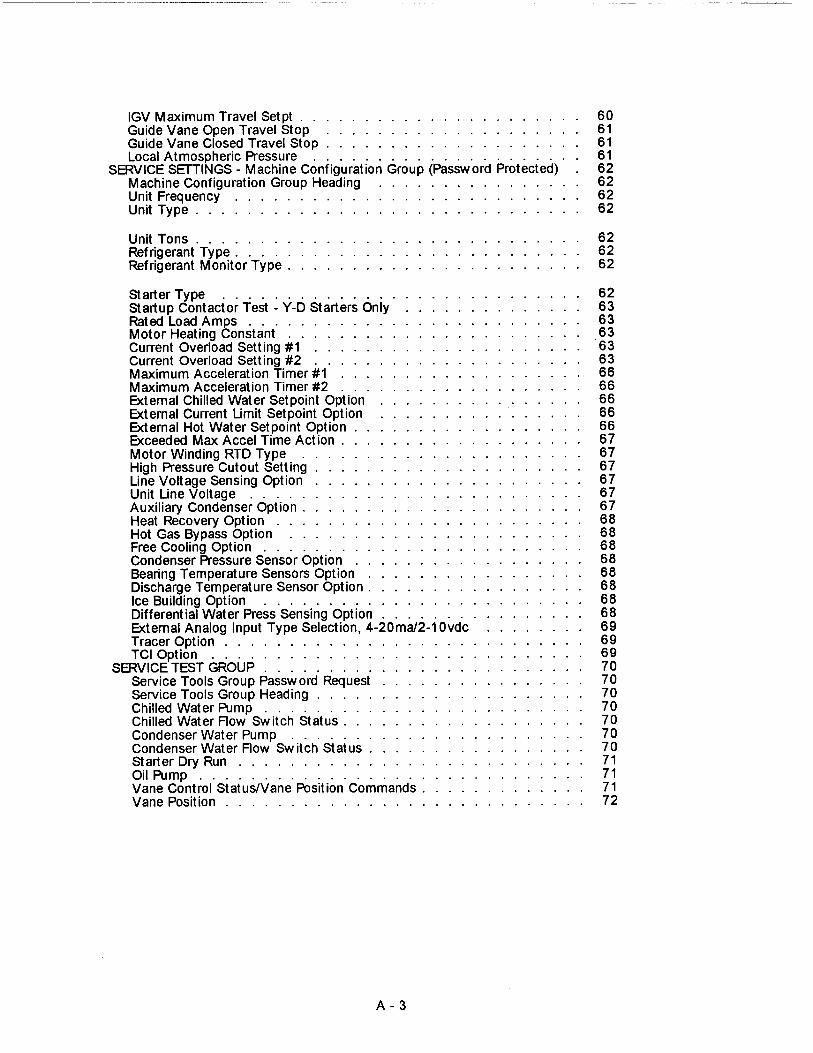
IGV Maximum Travel Setpt . . . . . . . . . . . . . . . . . . . . . .Gu ide Vane Open Travel Stop . . . . . . . . . . . . . . . . . . . .Guide Vane Closed Travel Stop . . . . . . . . . . . . . . . . . . . .Local Atmospher i c Pressure . . . . . . . . . .
SERVICE SETTINGS - Mach i ne Configurat ion Group (Password Protected) .Machine Configuration Group Head i ng . . . . . . . . . . . . . . . .Unit Frequency . . . . . . . . . . . . . . . . . . . . . . . . . . .Unit Type . . . . . . . . . . . . . . . . . . . . . . . . . . . . . .
6061616162626262
Unit Tons . . . . . . . . . . . . . . . . . . . . . . . . . . . . . . 62Refrigerant Type . . . . . . . . . . . . . . . . . . . . . . . . . . 62Refrigerant Mon itor Type . . . . . . . . . . . . . . . . . . . . . . . 62
Starter Type . . . . . . . . . . . . . . . . . . . .Startup Contactor Test - Y-D Starters Only . . . . . . . . . . . . . .Rated Load Amps . . . . . . . . . . . . . . . . . . . . . . . .Motor Heating Constant . . . . . . . . . . . . . . . . . . . . . . .Current Overload Setting #1 . . . . . . . . . . . . . . . . . . . . .Current Overload Sett i ng #2 . . . . . . . . . . . . . . . . . . . .Maximum Accelerat i on Timer #1 . . . . . . . . . . . . . . . . . . .Maximum Acceleration Timer #2 . . . . . . . . . . . . . . . . . .External Chilled Water Setpoint Option . . . . . . . . . . . . . . .External Current Limit Setpoint Option . . . . . . . . . . . . . . . .External Hot Water Setpo i nt Option . . . . . . . . . . . . . . . . . .Exceeded Max Accel Time Action . . . . . . . . . . . . . . . . . . .Motor Wi nd i ng RTD Type . . . . . . . . . . . . . . . . . . . . . .High Pressure Cutout Setting . . . . . . . . . . . . . . . . . . . . .Line Voltage Sensing Option . . . . . . . . . . . . . . . . . . . . .Unit Line Vo ltage . . . . . . . . . . . . . . . . . . . . . . . . .Auxil i ary Condenser Option . . . . . . . . . . . . . . . . . . . . . .Heat Recovery Option . . . . . . . . . . . . . . . . . . . . . . . .Hot Gas Bypass Opt i on . . . . . . . . . . . . . . . . . . . . . . .Free Cooling Option . . . . . . . . . . . . . . . . . . . . . . .Condenser Pressure Sensor Opt i on . . . . . . . . . . . . . . . . . .Bearing Temperature Sensors Opt ion . . . . . . . . . . . . . . . . .Discharge Temperature Sensor Option . . . . . . . . . . . . . . . . .Ice Building Option . . . . . . . . . . . . . . . . . .Different i al Water Press Sensing Option . . . . . . . . . .External Analog Input Type Selection , 4 -20ma/2-10vdc . . . . . . . .Tracer Option . . . . . . . . . . . . . . . . . . . . . . . . . . . .TCI Opt ion . . . . . . . . . . . . . . . . . . . . . . . . . .
SERVICE TEST GROUP . . . . . . . . . . . . . . . . . . . . . . .Service Tools Group Passwo rd Request . . . . . . . . . . . . . . . .Service Tools Group Heading . . . . . . . . . . . . . . . . . . . . .Chilled Water Pump . . . . . . . . . . . . . . . . . . . . . . . .Chilled Water Flow Sw i t c h Status . . . . . . . . . . . . . . . . . . .Condenser Water Pump . . . . . . . . . . . . . . . . . . . . . . .Condenser Water Flow Switch Status . . . . . . . . . . . . . . . . .Starter Dry Run . . . . . . . . . . . . . . . . . . . . . . . . . . .Oil Pump . . . . . . . . . . . . . . . . . . . . . .Vane Control Status/Vane Pos i tion Commands . . . . . . . . . . . .Vane Position . . . . . . . . . . . . . . . . . . . . . . . . . . .
626363636363666666666667676767676768686868686868686969697070707070707071717172
A-3

Product Coding Defin it i onIntroductionTypical Prod. Description BlockCVHE Product CodingExplanation
8 General Information8 Literature Change History8 About this manual8 Commonly Used Acronyms8 Warnings and Cautions9 Unit Nameplate
10 Mechanica l Operation -CVHE
10 Overview10 Cooling Only Cycle13 Compressor Lubrication
System - CVHE13 Motor Cooling System
16 Mechanica l Operation -CVHF
16 Overview16 Cooling-Only Cycle19 Compressor Lubrication
System - CVHF19 Motor Cooling System22 Free Cooling Cycle
(Optional) - CVHE/CVHF23 Heat Recovery Cycle (Optional)23 Auxiliary Condensers
242425272829303233
Chiller Control SystemUnit Control PanelChiller Module (1U1)Circuit Modul (1 U2)Stepper Module (1 U3)Options Module (1 US)Starter Module (2U1)Purge Module (3U1)Clear Language DisplayModule (1 U4)
34 Operator Interface34 Custom Report34 Chiller Report34 Chiller Operating Mode35 Friendly Modes
39 Chiller Report
41 Refrigeration Report
43 Compressor Report
45 Setting Group Keys
46 Operator Setting Group
Table ofContents
88 -Oil Change Procedure54 Field Startup Group Heading 88 -Replacing Oil Filter
88 -Replacement Procedure62 Service Settings Group - 89 Other Maintenance
Machine Configuration Requirements89 Lubrication
69 Service Test Group 89 Refrigerant Charge90 Recovery/Recycle Connections
73 Electrical Sequence of 90 Leak TestingOperation 91 Cleaning the Condenser
73 Chilled and Condenser 92 Cleaning the EvaporatorWater Flow Interlock Circuits 92 Control Settings and
73 UCP2 and "Wye-Delta" AdjustmentsStarter Control Circuits 92 Purge System
7474
78808181
81
82
828383838484
8486
87878787878888888888
Vane Actuator ControlCircuit Breaker 1CB3 OilPumpRestart InhibitControlsDifferential To Start/StopLeaving Water TemperatureCutoutLow Refrigerant TemperatureCutoutEnhanced CondenserLimit ControlFree CoolingHot Gas BypassUnit Start-Up Procedures--Daily Unit Start-UpSeasonal Unit StartupUnit Shutdown Procedures--Daily Unit ShutdownSeasonal Unit ShutdownTrouble Analysis
Periodic Ma intenanceOverviewPeriodic MaintenanceDaily Maintenance and ChecksWeekly MaintenanceEvery 3 MonthsEvery 6 MonthsOff-Season MaintenanceAnnual MaintenanceCompressor Oil Change onCVHE/CVHF units
93 Diagnostics
Forms:
ANNUAL INSPECTIONCHECKLIST
UCP2 "SETTINGS GROUP"MENU RECORD (Pages 1-4)
CENTRAVAC WITH UCP2COMMISSIONING CHECKLIST& START-UP TEST LOG(Pages 1-6)
START-UP TEST LOGWATER COOLED CENTRAVACSWITH UCP2 CONTROL PANELS(Pages 1-2)
The Tra ne Company urges that a ll HVAC servicers working on Trans equipmeM, orany manufacturer' s products, make every effort to eliminate, if possible , orvigorously reduce the emission of CFC, HCFC, and HFC refrigerants to theatmosphere resulting from installation, operation, routine maintenance, or majorservice on this equipment. Always act In a responsible manner to conserverefrigerants for continued use even when acceptable a lternatives are availa ble.
51 Service Sett ings Conservation and emission-reduction can be accomplished by followingrecorrwnended Trane service and safety procedures published In Trane gene ral
53 Service Settings Group service manuals "CTV-SB-8 1', "CTVSB42" and CFC-Guide 2. Copies of theseHeading manual s may be obta i ned by contacting your local Trane commercial product
representative .
CVHE-M-7 2 mAmerican Standard 1994

Product CodingDefinition
IntroductionThe CVHE 230-1250 and theCVHF 650-1280 is defined usingthe product definition andselection (PDS) system. Thissystem describes the productofferings in terms of a productcoding block which is made up offeature categories and featurecodes.
Typical ProductDescription Block
MODLCVHE DSEQIWHRTZ 50/60 TYPE SNGLEVTM IECU EVTH 28EVWC STD EVWP 2EVCO FLNG EVWA RERECDSZ 050L CDBS 500CDWT NMAR CDPR 150CDTY STD ORSZ 500AGLT NONE CNIF MICR
CVHE/CVHF ProductCoding Explanation
MODLUnit ModelCVHE = CenTraVac Di rect Drive
He rmet i cDevelopment Sequence " E"
CVHF = CenTraVac Di rect Dr iveHermeticDevelopment Sequence " F "
DSEQDesign SequenceFa ctory Assigned1W = UCP2
NTONUnit Nominal Capacity (Tons)CVHE Sequence E230 = 230 Tons250 = 250 Tons280 = 280 Tons300 = 300 Tons320 = 320 Tons360 = 360 Tons400 = 400 Tons450 = 450 Tons500 = 500 Tons560 = 560 Tons630 = 630 Tons710 = 710 Tons800 = 800 Tons890 = 890 Tons1120 = 11201250 = 1250
The operating components and when ordering replacement partsoptions for any Model CVHE/ or requesting service. An exampleCVHF CenTraVac unit can be of a typical product code is givenidentified by referring to the alpha- on this page.numeric product identificationcoding block located on the name- Note: Unit-mounted starters areplate for the unit. The coding block identified by a separate numberprecisely identifies all charao- found on the starter.teristics of a unit. Be sure to referto the service model number
NTON 500CPKW 403EVSZ 050LEVWT NMARCDTM IECUCDWC STDCDCO FLNGPURG HERMSRTY RPIR
CVHF Sequence F650 = 650 Tons770 = 770 Tans800 = 800 Tons890 = 890 Tons910 = 910 Tons1060 =1060 Tons1 120 = 1 120 Tons1250 = 1 250 Tons1280 =1 250 Tons
VOLTUnit Voltage200 = 200/60/3208 = 208/60/3230 = 230/60/3380 = 380/60/50/3440 = 440/60/3460 = 460/60/3480 = 480/60/3575 = 575/60/3600 = 600/60/32300 = 2300/60/32400 = 2400/60/33300 = 3300/60/50/34000 = 4000/6 0/34160 = 4160/60/34800 = 4800/6 0/36600 = 6600/60/3
HRTZUnit Hertz50 = 50 Hertz60 = 60 Hertz
VOLT 460CPIM 253EVBS 500EVPR 150CDTH 28CDWP 2CDWA REREHGBP W/O
TYPEUnit TypeSNGL = S i ngle Condenser
(Coo l ing On ly)HTRC = Heat RecoveryAUX = Aux i l i ary Condeser
TYPOUnit TypeSTD = Standard ShellsEXTD = Extended Surface Shells
CPKWCompressor Motor Kilowatts142 = 142 KUV154 = 154 KW171 = 171 KW187 = 187 KW204 = 204 KW231 = 231 KW257 = 257 KW287 = 287 KV1!323 = 323 KW361 = 361 KW403 = 403 KW453 = 453 KW512 = 512 K1N588 = 588 K1N653 = 653 KW361 = 361 KW745 = 745 KW856 = sss KW957 = 957 KW1062 = 1062 KW1228 = 1228 KW
3CVHE-M-7

CPIMCompressor Impeller-Diameter
3-STAGE 2-STAGE
220
222
223
225
227
228
230
232
233
235
237
238
240
242
243
245
247
248
250
252
253
255
257
258
260
262
263
265
267
268
270
271
272
273
274
275
276
277
278
279
280
281
282
283
284
285
286
287
288
289
290
291
292
293
294
295
296
22 . 0
22 . 5
22 . 5
22 . 5
23 . 0
23 . 0
23 . 0
23 . 5
23 . 5
23 . 5
24 .0
24 . 0
24 . 0
24 . 5
24 .5
24 . 5
25 . 0
25 . 0
25 . 0
25 . 5
25 . 5
25 . 5
26 . 0
26 . 0
26 . 0
26 . 5
26 . 5
26 . 5
27 . 0
27.027 . 0
22 . 022 . 022 . 522 . 522 . 523 . 023 . 023 . 023 . 523 . 5
23 . 524 . 024 . 024 . 024 . 524. 524 . 525 . 025 . 025 . 025 . 525 . 525 . 526 .026 . 026 . 026 . 526 . 5
26 . 527.027 . 0
27 . 5 27 . 027 . 5 27 . 5
27 . 5 27 . 5
28 . 0 27 . 5
28 . 0 28 . 0
28 . 0 28 . 0
28 . 5 28 . 028 . 5 28 . 5
28 . 5 28 . 5
29 . 0 29 . 029 . 0 29 . 0
29 . 0 29 . 0
29 . 5 29 . 529 . 5 29 . 5
29 . 5 29 .5
22 . 022 . 022 . 022 .522 . 522 . 523 . 023 .023 . 023 . 523 . 523 . 524 . 024 . 024 .024 . 524 . 524 . 525 . 025 . 025 . 025 . 525 . 525 . 526 .026 . 026 . 026 . 5
26 . 526 . 527 . 0
27 . 027. 0
27 . 5
27 . 527 . 5
28 . 0
28 . 028 . 0
28 . 5
28 . 528 . 5
29 . 0
29 . 029 . 0
29 . 5
27 . 00 27 . 00
27 .25 27 .00
27 . 25 27 . 2527. 50 27.2527 . 50 27 . 5027 . 75 27 .50
27 . 75 27 . 7528 . 00 27 . 7528 . 00 28 . 0028 . 25 28 . 00
28 . 25 28 .25
28 . 50 28 . 2528 . 50 28 . 5028 . 75 28 . 50
28 . 75 28 . 75
29 . 00 28 . 7529 . 0 29 . 029 . 25 29 . 029 . 029 . 25 29 . 25
29 . 50 29 . 2529 . 50 29 . 5029 .7 5 2 9. 5
297 30.0 29.5 29.5 EVBS298 30.0 30 . 0 29.5 29.75 29.75 Evaporator Tube Bundle Size299 30 . 00 29 . 75 200 = 200 Nom i nal Tons300 30 . 0 30 . 0 30 . 0 30 . 00 30 . 00 220 = 220 Nom inal Tons
301 30 .25 30 . 00 230 = 230 Nominal Tons
302 30 . 5 30 . 0 30 . 0 250 = 250 Nominal Tons
303 30 . 5 30 . 5 30 . 00 30 .25 30 . 25 280 = 280 Nomina l Tons
304 30 .50 30 .25 320 = 320 Nominal Tons
305 30 . 5 30 . 5 30 . 5 30 . 50 30 . 50 350 = 350 Nominal Tons
306 30 .75 30 . 50360 = 360 Nominal Tons
307 31 . 0 30 . 5 30 . 5400 = 400 Nominal Tons
308 31 .0 31 . 0 30 . 5 30 . 75 30 .75450 = 450 Nominal Tons500 = 500 Nominal Tons
309 31 . 00 30 .75 550 = 550 Nominal Tons310 31 . 0 31 . 0 31 .0 31 . 00 31 .00 560 = 560 Nom inal Tons311 31 . 25 31 . 00 630 = 630 Nominal Tons312 31 . 5 31 .0 31 . 0 710 = 710 Nominal Tons313 31 . 5 31 . 5 31 . 3 31 . 25 31 . 25 800 = 800 Nominal Tons314 31 . 50 31 . 25 890 = 890 Nomina l Tons315 31 . 5 31 . 5 31 . 5 31 . 50 31 . 50 900 = 900 Nominal Tons
316 3 1. 75 31 . 50 980 = 980 Nominal Tons
317 32 . 0 31 . 5 31 . 5 1000 = 1000 Nom i nal Tons
318 32 . 0 32 . 0 31 . 5 31 . 75 31 .75 1080 = 1080 Nom i nal Tons
319 32 . 00 31 . 75 11 20 = 1120 Nominal Tons
320 32 . 0 32 .0 32 .0 32 .00 32 . 00 1 220 = 1220 Nominal Tons
321 32 .25 32 . 00 1250 = 1250 Nomina l Tons
322 32 . 5 32 . 0 32 . 01400 = 1400 Nominal Tons
323 32 . 5 32 . 5 32 . 0 32 . 25 32 . 251420 = 1420 Nominal Tons
324 32 . 50 32 . 251450 = 1450 Nominal Tons1610 = 1610 Nominal Tons
325 32 . 5 32 . 5 32 . 5 32 . 50 32 . 50 1760 = 1760 Nominal Tons326 32 . 75 32 . 50 1900 = 1900 Nominal Tons327 33 . 0 32 . 5 32 . 5 2100 = 2100 Nom i nal Tons328 33 .0 33 . 0 32 . 5 32 . 75 32 . 75329 33 . 00 32 . 75
EVwC330 33 . 0 33 . 0 33 . 0 33 . 00 33 .00
E t W t b
EVTMEvaporator Tube MaterialIECU = Internally Enhanced CU -1"SBCU = Smooth Bore CU 3/4"SB91 = Smooth Bore CU/NI 90/10 3/4"TECU = Internally Enhanced CU - 3/4"
EVTHEvaporator Tube Wall Thickness28 = . 028 Wall Th i ckness35 = . 035 Wall Th ickness
EVSZEvaporator Shell Size032S = 300 Ton Short Shel l032L = 300 Ton Long Shel l050S = 500 Ton Short Shell050L = 500 Ton Long She l l080S = 800 Ton Short She ll080L = 800 Ton Long Shell125L = 1250 Ton Long Shell140E = 1 400 Extended Length She l l142M = 1400 Ton Med i um Shell142 L = 1400 Ton Long Shel l210M = 21 OOTonMediumShell210L = 2 1 00 Ton Long She l l
vapora or a er oxConstructionSTD = Standard WeldedASME = ASME We lded Water-Side
EVWPEvaporator Water Passes1 = One Pass2 = Two Pass3 = Three Pass
EVWTEvaporator Waterbox TypeMAR = MarineNMAR = Non-Marine
EVPREvaporator Wate rsi de P ressure1 50 = 1 50 P SIG300 = 300 PSIG
CVHE-M-7 4

EVCOEvaporator WaterboxConnectionVICT = Victaul i cFLNG = Flanged
EVWAEvaporator WaterboxArrangementFRNT = In Front/Out FrontREAR = I n Rea dOut RearLFRR = In LH Front/Out RH RearRRLF = In RH Rea r/Out LH FrontLRRF = In Rea r/Out RH FrontRF LR = In Front/Out LH RearLFLR = I n LH Front/Out LH RearLRLF = I n LH Rear/Out LH FrontRFRR = In RH Front/Out RH RearRRRF = In RH Rear/Out RH FrontEND = I n One End/Out the OtherRERE = In RH End/Out RH EndLELE = In LH End/Out LH End
CDTMCondenser Tube MatertalIECU = Internal ly Enhanced CU1 "SBCU = Smooth Bore CU 3/4"SB91 = Smooth BoreCUNI 90/10 3/4"SB73 = Smooth Bore CUNI 70/30 3/4"SBT1 = Smooth Bore Titanium 3/4 'TECU = Internally Enhanced CU3/4"
CDTHCondenser Tube Thickness28 =.028 V11a l l Thickness35 = . 035 Wa l l Thickness42 = . 042 Wa l l Thickness49 = . 049 Wall Thickness
CDSZCondenser Shell Size032S = 320 Ton Short Shell032L = 320 Ton Long Shell050S = 500 Ton Short Shell050L = 500 Ton Long Shell080S = 800 Ton Short Shell080L = 800 Ton Long Shell125L = 1250 Ton Long Shell140L = 1400 Ton Long Shell142S = 1400 Ton Short Shell142L = 1400 Ton Long Shell210S = 2100 Ton Short Shell210L = 2100 Ton Long Shell
CDBSCondenser Tube Bundle Size200 = 200 Nominal Tons220 = 220 Nominal Tons230 = 230 Nominal Tons250 = 250 Nom inal Tons280 = 280 Nominal Tons320 = 320 Nominal Tons350 = 350 Nominal Tons360 = 360 Nominal Tons400 = 400 Nominal Tons
450 = 450 Nominal Tons STD = Standard Welded500 = 500 Nominal Tons ASME = ASME We lded550 = 550 Nominal Tons560 = 560 Nominal Tons TSN630 = 630 Nominal Tons Tube Sheet Construction710 = 710 Nominal Tons STD = Standard Welded800 = 800 Nominal Tons ASME = ASME Welded890 = 890 Nom i nal Tons900 = 900 Nom i nal Tons
CHTM980 = 980 Nom inal Tons1000 = 1000 Nominal Tons Heat Rec . Condenser
1080 = 1080 Nomina l Tons Tube Material
1120 = 1120 Nominal TonsIECU = Intemal Enhance CU- 1 "
1220 = 1220 Nominal TonsSBCU = Smooth Bore CU 3/4"
1250 = 1250 Nominal TonsS691 = Smooth Bore CU/NI 90/103/4"
1400 = 1400 Nominal TonsSB73 = Smooth Bore CU/NI 70/30 3/4"
1420 = 1420 Nominal TonsSBTI = Smooth Bore Titanium 3/4"
1610 = 1610 Nominal TonsTECU = Internally Enhanced CU 3/4"
1760 = 1760 Nom i nal Tons1900 = 1900 Nom i nal Tons CHTH2100 = 2100 Nom i nal Tons Heat Rec . Condenser Tube Wall
CDWCCondenser Water BoxConstructionSTD = Standard WeldedASME = ASME We lded - Water-Side
CDWPCondenser Water Passes2 = 2 Pass
CDWTCondenser Waterbox TypeMAR = MarineNMAR= Non-Marine
CDPRCondenser Water Side Pressure150 = 150 PSIG300 = 300 PSIG
CDCOCondenser WaterboxConnectionVICT = Victaul icFLNG = Flanged
CDWACondenser WaterboxArrangementLFLF = In LH Front/Out LF FrontLRLR = In LH Rear/Out LH RearRFRF = In RH Front/Out RH FrontRRRR = In RH Rear/Out RH RearLFLR = In LH Front/Out LH RearLRLF = In LH Rear/Out LH FrontRFRR = In RH Front/Out RH RearRRRF = In RH Rear/Out RH FrontRERE = In RH End/Out RH EndLELE = In LH End/Out LH End
CDTYCondenser ConstructionRefrigerant Side
Thickness28 = .028 Wall Thickness35 = . 035 Wall Thickness42 = . 042 Wall Thickness49 = .049 Wal l Thickness
CHSZHeat Rec. Condenser Shell Size032S = 320 Ton Short Shell032L = 320 Ton Long Shell050S = 500 Ton Short Shell050L = 500 Ton Long Shell080S = 800 Ton Short Shell080L = 800 Ton Long Shell125L = 1250 Ton Long Shell140L = 1400 Ton Long Shell142S = 1400 Ton Short Shell142L = 1400 Ton Long Shell210S = 2100 Ton Short Shell210L = 2100 Ton Long Shell
CHBSHeat Rec . Condenser TubeBundle Size200 = 200 Nom i nal Tons230 = 230 Nominal Tons250 = 250 Nominal Tons280 = 280 Nomina l Tons320 = 320 Nomina l Tons360 = 360 Nominal Tons400 = 400 Nominal Tons450 = 450 Nominal Tons500 = 500 Nominal Tons560 = 560 Nominal Tons630 = 630 Nominal Tons710 = 7 1 0 Nom i na l To ns800 = 800 Nominal Tons900 = 900 Nom i nal Tons1000 = 1000 Nomina l Tons1120 = 1120 Nominal Tons1220 = 1220 Nominal Tons1250 = 1 250 Nominal Tons1 400 = 1400 Nominal Tons1420 = 1420 Nominal Tons1610 = 1610 Nominal Tons1760 = 1760 Nominal Tons
CVHE-M-7

1900 = 1900 Nominal Tons2100 = 2100 Nominal Tons
CHWCHeat Rec . Condenser WaterboxConstructionSTD = Standa rd WeldedASME = ASME We lded - Water Side
CHWPHeat Rec . Condenser WaterPasses2 = 2 Pass
CHWTHeat Rec . Condenser WaterboxTypeMAR = Ma ri neNMAR = Non-Ma ri ne
CHPRHeat Rec . Condenser WaterboxSide Pressure150 = 150 PSIG300 = 300 PS I G
CHCOHeat Rec. Condenser WaterboxConnectionsVICT = VictaulicFLNG = Flanged
CHWAHeat Rec . Condenser WaterboxArrangementLFLF = In LH Front/Out LF FrontLRLR = In LH Rea r/Out LH Rea rRFRF = I n RH Front/Out RH FrontRRRR = In RH Rear/Out RH RearLFLR = In L H Front/Out LH RearL RLF = In LH Rear/Out LH FrontRFRR = In RH Front/Out RH RearRRRF = In RH Rear/Out RH FrontRERE = I n RH End/Out RH End
LELE = In LH End/Out LH End
CABSAuxiliary Condenser NominalTonnage80 = 80 Nom inal Tons130 = 130 No m ina l Tons
CVHE-M-7
CAWC ORSZAuxiliary Condenser Waterbox Orifice SizeConstruction 130 = Orifice Size
STD = Standard Welded 140 = Orifice SizeASME = ASME Welded - Water Side 160 Orifice Size
180 = Orifice Size
CATM 200 = Orifice Size
Auxiliary Condenser Tube 230 = Orifice Size
Material 250 = Orifice Size
IECU = Internal Enhance CU-1" 280 = Orifice Size
SBCU = Smooth Bore CU 3/4" 320 = Orifice Size
S691= Smooth Bore CU/N I 90/10 3/4" 360 = Orifice Size
SB73 = Smooth Bore CU/NI 70/30 3/4" 375 = Orifice Size
SBT1 = Smooth Bore Titanium 3/4" 400 = Orifice Size
TECU = Internally Enhanced CU -3/4" 415 = Orifice Size450 = Orifice Size
CATH460 = Orifice Size500 = Orifice Size
Auxiliary Condenser Tube Wall 510 = Orifice SizeTh ic kness 560 = Orifice Size28 = .028 Wa!I Thickness 585 = Orifice Size35 = .035 Vlfall Thickness 630 = Orifice Size42 =.042 Wall Thickness 650 = Orifice Size
710 = Orifice SizeCACO 790 = Orifice SizeAuxiliary Condenser Waterbox 800 = Orifice SizeConnection 900 = Orifice SizeVICT= Victaulic 990 = Orifice SizeFLNG =Flanged 1000 = Orifice Size
1100 = Orifice Size
CAPR 1120 = Orifice SizeAuxiliary Condenser Water Side 1250 = Orifice SizeP ressure 1265 = Orifice Size
150 = 150PSIG 1400 = Orifice Size
300 = 300 PSIG 1540 = Orifice Size1660 = Orifice Size
CAWT1800 = Orifice Size
Auxiliary Condenser Waterbox1810 = Orifice Size
Type1970 = Orifice Size2150 = Orifice Size
MAR = ManneNMAR = Non-Marine
PURGE
CAWAPurge Unit
Auxiliary Condenser WaterboxPURE = Purifier Uni t
ArrangementSPKGLFLF = In LH Front/Out LF Front
LRLR = In LH Rear/Out LH Rear Shipping Package
RFRF = I n RH Front/Out RH FrontDOM = Domestic
RRRR = In RH Rear/Out RH RearEXP = Export
LFLR = In LH FrontOut LH RearFULL = Export
LRLF = In LH Rear/Out LH FrontRFRR = In RH Front/Out RH RearRRRF = In RH Rear/Out RH FrontRERE = In RH End /Out RH End
LE LE = In LH End/Out LH End
ECTYEconomiser Orifice TypeWEOR = WeldedREOR= Bolted Removable
6
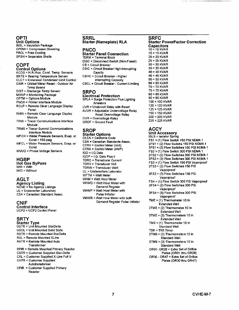
OPTIUnit OptionsINSL = Insu l ation Package
CPDW = Compressor Doweling
FRCL = Free Cooling
SPSH = Separable Shells
COPTControl OptionsACOS = H . R ./Aux . Cond . Temp . SensorsBRTS = Bearing Temperatu re SensorCLCT = Enhanced Condenser Lim it ControlCWR = Chilled Water Reset - Outdoor Air
Temp BasedD I ST = Discharge Temp SensorMONP = Mon itoring PackageOPTM = Options ModulePNCH = Printer Interface ModuleRCLP = Remote Clear Language Display
PanelRHIN = Remote Clear Language D i sp l ay
ModuleTRMI = Tracer Communications I nte rface
ModuleTRMS = Tracer Summit Communications
Interface ModuleWFCH = Water Pressure Sensors , Evap . or
Cond > 150 psigWFCL = Water Pressure Sensors , Evap . or
Cond .WVUO = Ph ase Vo ltage Sensors
HGBPHot Gas ByPassWith = WithW/O = Without
AGLTAgency ListingNONE = No Agency ListingsUL = Underwriter LaboratoryCSA = Canadian Standard Assoc .
CNI FControl I nte rfaceUCP2 = UCP2 Control Pane l
SRTYStarter TypeUSTR = Un i t Mounted StarDe ltaUSOL = Un it Mounted Solid StateRSTR = Remote Mounted StarDeltaRXL = Remote Mounted XL ineRATR = Remote Mounted Auto
Transfo rmerRPIR = Remote Mounted Primary ReactorCSTR = Customer Supplied Star- DeltaCXL = Customer Supplied X-Line Full VCATR = Customer Supplied
AutotransformerCPIR = Customer Suppl i ed P rimary
Reactor
SRRL SRFCStarter (Nameplate) RLA Starter PowerFactor Correction
Capacitors
PNCO 10 = 10 KVAR
Starter Panel Connection 15 = 15 KVAR
TERM = Terminal Block 20 = 20 KVAR
DISC = Disconnect Switch (Non-Fused) 25 = 25 KVAR
CB = Circuit Breaker 30 = 30 KVAR
CB I C = Circuit Breaker High Interupting 35 = 35 KVAR
Capc ity 40 = 40 KVAR
CBHC = Circuit Breaker - H igher 45 = 45 KVAR
Interrupt i ng Capacity 50 = 50 KVAR
CBCL = Circuit Breaker - Current L i miting 60 = 60 KVAR70 = 70 KVAR
SRPO75 = 75 KVAR
Electrical Protection 80 = 80 KVAR
SPLA = Surge Protection P l us Lighting 90 = 90 KVAR
Arrestors 100 = 100 KVAR
UVR = Undervo l t Relay with Reset 120 = 120 KVAR
AUVR = Adj ustable Undervol tage Relay 1 25 = 125 KVAR
Reset Overvoltage Relay 150 = 150 KVAR
OVR = Overvoltage Relay 200 = 200 KVAR
GRDF = Ground Fau l t 225 = 225 KVAR
SROPStarter OptionsCLCA = California CodeCSA = Canadian Standards Assoc .CTRV = Control Meter (Volt)CTRA = Control Meter (AMP)IQD = I . Q DataIQDP = I . Q . Data Plus IITDRC = Transducer CurrentTDRV = Transducer VoltTDRW = Transducer WattUL = Underwriters Labo ratorWTTM = Watt MeterWHM = Watt Hour MeterWHMD = Watt Hour Meter w ith
Demand RegisterWHMP = Watt Hour Meter with
Pulse In i tiatorWHMB = Watt Hour Meter with both
Demand Register Pulse Initiator
ACCYUnit AccessoryISLS = Isolator SpringFS1 = (1) Flow Switch 150 PSI NEMA I2FS1 = (2) Flow Switchs 150 PSI NEMA 13FS1 = (3) Flow Switches 150 PSI NEMA 1FS2 = (1) Flow Switch 300 PSI NEMA 12FS2 = (2) Flow Switches 300 PSI NEMA 13FS2 = (3) Flow Switches 300 PSI NEMA 1FS3 = (1) Flow Switch 150 PSI Vaporproof2FS3 = (2) Flow Switches 150 PSI
Vaporproof3FS3 = (3) Flow Switches 150 PSI
VaporproofFS4 =(1) Flow Switch 300 PSI Vaporproof2FS4 = (2) Flow Switches 300 PSI
Vaporproof3FS4 = (3) Flow Switches 300 PSI
VaporproofTME = (1) Thermometer 101n
Extended Well2TME = (2) Thermometer 10 In
Extended Well3TME = (3) Thermometers 10 In
Extended WellTMS = (1) Thermometer 10 In
Standard WellT5R = TR5 Timer2TMS = (2) Thermometers 10 In
Standard Well3TMS = (3) Thermometers 10 In
Standard WellOR01- OR28 = Extra Set of Orifice
Plates (OR01 thru OR28)OR30 - OR47 = Extra Set of Orifice
Plates (OR30 thru OR47)
CVHE-M-7

Literatu re Change History
CVHE-M-7 (February 1994)
Original issue of manual;describes proper operation andmaintenance of 50 Hz. or 60 Hz.CVHE units of "1 W" designsequences with UCP2 micro-computer-based control systemsand CVHF 650-1280 "EO " designsequences with UCP2micro-computer-based controlsystems.
About this manual
Th is book let describes theoperat i on and maintenance of 50Hz . or 60 Hz . Model CVHE andCVHF CenTraVac chil lersequ i pped with m icro-computer-based control systems , whetherstandard (cooling) or heating-recovery . By carefully reviewingth is information and following theinst ructions given , the owner/operator can successfully operateand mainta i n a CVHE or CVHFun it .
Diagnostic information is providedat the end of this manual to allowthe operator to identify a numberof system malfunctions, shouldany develop. (If mechanicalproblems do occur, however,contact a qualified serviceorganization to ensure properdiagnosis and repair of the unit.)
Commonly UsedAcronyms
For convenience, a number ofacronyms are used throughoutthis manual. These acronyms arelisted alphabetically below, alongwith the "translation" of each:
GeneralInformation
AFD = Adjustable Frequency Warn i ngs and CautionsDrive
Notice that warnings and cautionsASME = American Society of
appear at appropriate interva lsMechanical Engineers
throughout this manual. WarningsASHRAE = American Society of
are provided to alert installingHeating, Refrigerating and Air
contractors to potential hazardsConditioning Engineers
that could result in personal injury
BAS = Building Automationor death while cautions are
SystemCABS = Auxiliary Condenser
Tube-Bundle SizeCDBS = Condenser Bundle Size
CDSZ = Condenser Shell SizeCLD = Clear Language DisplayCWR =Chilled Water Reset
designed to alert personnel toconditions that could result inequipment damage .
DTFL = Design Delta-T at FullLoad (i . e ., the difference betweenentering and leaving chilled watertemperatures)ENT = Entering Chil led WaterTemperatureFC = Free Cooling
GPM = Gallons-per-minuteHGBP = Hot Gas BypassHVAC = Heating , Ventilating , andAir Conditioning
IE = Intemally-Enhanced TubesIPC = InterprocessorCommunicationLBU = La Crosse Business Unit
LCD = Liquid Crystal DisplayLED = Light Emitting DiodePFCC = Power Factor CorrectionCapacitor
PSID = Pounds-per-Square-Inch(differential pressure)PSIG = Pounds-per-Square-Inch(gauge pressure)RCLD = Remote Clear LanguageDisplay
UCP2 = Chiller Control Panel forCenTraVacs
Your personal safety and theproper installation of this machinedepend upon the strict observanceof these precautions .
Unit Nameplate
The CVHE or CVHF unitnameplate is located on the leftside of the un it control panel(UCP) . A typical unit nameplate isillustrated in Figure 1 . Thefollowing information is providedon the unit nameplate .
- Service model and sizedescriptor .
- Unit serial number- Identifies unit electricalrequirements
- List correct operating chargesand type of refrigerant
- Lists unit test pressures andmaximum operating pressures .
- Identifies unit Installation andOperation and Maintenancemanual
- Product descript ion block(identifies all unit componentsand unit "design sequence "(used to order literature andmake other inquiries about theun it).
- L i sts drawing numbers for unitw i r i ng d iagrams .
CVHE -M -7

Figure 1Typical Unit Nameplate
Unit Modeland Size Descriptor
Unit and MotorElectrical Data -
Unit RefrigerantCharge Information
Unit Service Literature
' l j
44D 1 .---L : C : VI-If.:: 71 0t1uI7E : l_ . NO , f;Vl -IL(•)7SNfitWW3lJV272EiV- 'rE:SSiBCOOOOC1OUYA0Ot700
Sl:: I ; IAI . _ iJU : t_9 3 .J09 :341
r;:i._e.crritcAL ChIAFiAC 'fl : R :[SiTCS
liil 'fF: A VDl_i ' r1GL: 41,.5(7 VOLTS 60F1Z 3 PH
V OLT A G E U T ILIZA T ION I; AN i;E:: 3 7 44 - 4576 VAC
Nl: fdl idUM CTIiGlJI7 AFff' F§CT7 'f : 107 AMPS
MA XI MUM F USE: 475 AMPS
MAXIMUM C IRCUIT BRFAI(E f2 : 17 5 AMPS
MA X IMUM OVERLOAD Y(:fE• : 90 AMPSMAX MAX
V O LTS-AC 1-17_ PH RL. A L R A Y L fiAD
ciiHF•fiG: SS01i t4i: iT'OR 060 60 3 0 5 .0 436 0
(i7: 1 . _ PUMP MO T OR 115 60 1 4.9 F LA
D :CL. T ANK PIE : ATE:k 1 1 5 60 1 1000 WATT S
CONTROL C I RCU I T 1S5 60 1 60 VA MAX
PUR G E COMP M1R f SS 60 1 7.0 FLFa
WhIE:h! MOTOR C(7Ni ";01 ._L .. CR PROVIDED BY OTHERS
TRANE i_ N rr.NEEF<zNr.. SPEC. s60e-0067 APPLIES
i;ENr:_r,ai_ r,HArtacrr_r, 1 911rsI:l i_ FRTC: f : RANT SYSTEM7f. i BE P': LI _ I ._ D ChiAl'iUli AC:TI!AL _ I _. Y CFIttIiGLU
WITH 1450 LBS. OF R -- f:3 W) . TH LCt ,S. OF h 1 :? 3
t4F1 ;C I : Ml . li4 f2L: F " R :[GE: fiAtdT WCiI<KTNG f'REC' ;;lJf{C :
h IT S TDI::: Q I'STi; L O sznr_ f .`.i 1='.S: fG
1=n C i Of;Y 'i CS "f " PP; f: S:; U FcF_
H I STIiI;_ 4 5 .fi P ' S' IG LO ti IDF 45 I '-' S :[G
F TG: I.. T i I ... L : A I< '1" F:: .3 1 F ' P i E : SSUI:I= 8 f-' S7f.; MAX .
TESTED AT F'SIG
I ... E : FlIi I ' f' S'i ' AND CIiAI; G :[NG SF'LCIFJ: C:A ' i ' 7 '. C ? t! ARE SUF'I '-'I . _IIi:::U
IN i:ONtFii]L f'ANl: : l ... (SERVICE LITERATURE Mr1tJUAl .. 3
MA N UI' Fl i;' C 'L ! R E li UNDER ONE OR MORE 01- i ' FII: FOLLOWING
U.S. PATENTS : 3 39Fl545 -- 346S68 :3 - 3E3MS4 742 :32 ..53 3 .... 461 3 6 03 4 46E199f, 'i 4 0 51 90
4751653 4803 732 - 50 :31410
SC_ FiVT[ ; E : L .:Ci[: I'i' A "i LIRE_
1 NS1FJ... I ... A1 ' 10 P! Mr; fd l!AI_
i?I ' F. Rf^1 ' ]: C1tJ/hSA] : N 'i[^N^1t^Cl:. HANUoI ...
Product Description Block-- {i=•Rt?x>U,-T rar:Sr.::r,IF>rrOra:
M f.illL . i:VHEVOL_ "f 4160; y F, D :; "i G
E :: V "ft1 'i ECUi_:viss 710r:::vw-r NMi;r;I_ `,'WA I_ f:_t_ECDSZ 080L_Cli1JF' 2L' D i:0 V :CLT
7.iT 'f STDPURt; I'UfiLACf: ; Y :?FSS
CN :[P UCI' ?
SRTY It:(Lf.-: F I_D WATL
R E'F G 1 2 3
I)3l:(^ 1WI - IPi1 :i. 60CF'KW 598l'-_ V 'i FI 20F' VWC S 'fDEVPR ti 150i:T i 'iH TECUt ] I)[i+S £300i: DWT NMAR
CDWA LE: LF_f.:: CTY WEOR,S'f'I<1 : DOM
I1GD 1" ' W1 " 1 ' Ii
CCiF'7 i ' I ':M T
S PJi L . 94
CF L . T) Wf-1 'i[ :
9
CVI I C-I N -t3
CVI^ I;i- H --7
N ir.iN -r t <,YYI'-' L : SiJGL
C F I M ?'i 2
EVSZ 0801_rvwP .>
E v i::[i v 7 . t;r
CDTH 2EsCDWC SI' I ?
CDPR 1 .15 0CDTY STDORSZ 1300CF' 'T7 : I NSLA LI_ 'T NONE
CUf '' T ' Esl: ' T ' S
P'NCU ISSW
1I: Si CW 'T.yi
CVHE-M-7
Overview
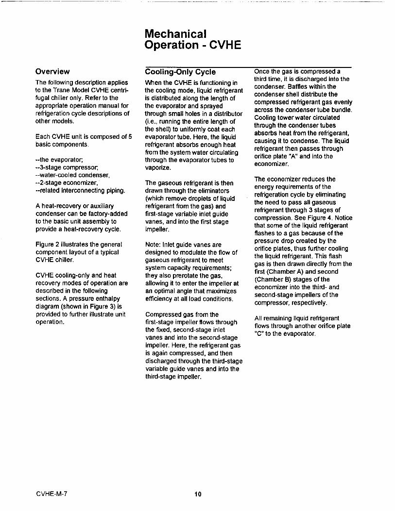
The following description appliesto the Trane Model CVHE centri-fugal chiller only. Refer to theappropriate operation manual forrefrigeration cycle descriptions ofother models.
Each CVHE unit is composed of 5basic components .
--the evaporator,--3-stage compressor,--water-cooled condenser,--2-stage economizer,--related interconnecting piping
A heat-recovery or auxiliarycondenser can be factory-addedto the bas ic unit assembly toprovide a heat-recovery cycle .
Fi gure 2 i l lustrates the generalcomponent layout of a typicalCVHE chiller .
CVHE cool i ng-only and heatrecovery modes of operation aredescribed in the followingsect ions . A pressure enthalpydiagram (shown in Figure 3) isprovided to further illustrate un itope rat i on .
MechanicalOperation - CVHE
Cooling-Only Cycle On ce the gas is compressed a
When the CVHE is functioning inthird time , it is discharged into the
the cool ing mode , liquid refrigerantcondenser. Baffles within the
is distributed along the length ofcondenser shell distribute the
the evaporator and sprayedcompressed refrigerant gas evenly
through small holes in a distributoracross the condenser tube bundle .
(i . e ., running the entire length ofCooling tower water circulated
the shell) to uniformly coat eachthrough the condenser tubes
evaporator tube . Here , the liquidabsorbs heat from the refrigerant ,
refrigerant absorbs enough heatcausing it to condense . The liquid
from the system water circulatingrefrigerant then passes throughorifice plate "A" and into the
through the evaporator tubes toeconomizer.
vaporize .
The gaseous refrigerant is thendrawn through the eliminators(which remove droplets of liquidrefrigerant from the gas) andfirst-stage variable inlet guidevanes , and into the first stageimpeller.
Note: Inlet guide vanes aredesigned to modulate the flow ofgaseous refrigerant to meetsystem capacity requirements;they also prerotate the gas,allowing it to enter the impeller atan optimal angle that maximizesefficiency at all load conditions.
The economizer reduces theenergy requirements of therefrigeration cycle by eliminatingthe need to pass all gaseousrefr igerant through 3 stages ofcompression . See Figure 4 . Noticethat some of the liquid refrigerantflashes to a gas because of thepressure drop created by theor ifice plates , thus further coolingthe liquid refrigerant . This flashgas is then drawn directly from thefirst (Chamber A) and second(Chamber B) stages of theeconomizer into the thi rd- andsecond-stage impellers of thecompressor , respect ively .
Compressed gas from thefirst-stage impeller flows throughthe fixed, second-stage inletvanes and into the second-stageimpeller. Here, the refrigerant gasis again compressed, and thendischarged through the third-stagevariable guide vanes and into thethird-stage impeller.
All remaining liquid refrigerantflows through another orifice plate"C" to the evaporator .
CVHE-M -7 10
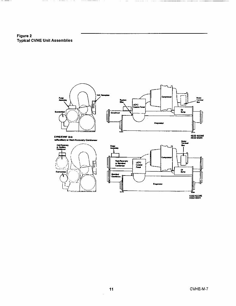
Figure 2Typical CVHE Unit Assemblies
CVFE/C1A# Unft.rAu.Y.n «w.«n. eov.ry cene«n.r
Econ.wr.;
••i ^ ^ .-- •
..._(
.._..'
^I,^'^•---^' ,
ft."
^M
LICP2..^ ^,,wc^..
E..vo..w cc43S'23s3tE4sas-8sa
11
MebrTa+irl!an
aA
4S3Z-8236Easas-esoa
CVHE-M-7

Figure 3CVHE Pressure/Enthalpy Curve
Figure 4CVHE 2-Stage Economizer
P^ Condenser
a HiyhSide Economizer
„ P Low-Side Economizer
ffi ^^ Evaporetor
14
Ori fice
Pla te A
Entha lpy (BTU/LBM)
7mp
Compressor(3rd Stape)
mpresaord Stage)
reasor(1 at Stage)
Refriaennt Gas Refrigerant GasOut to 3rd-Stage Out to 2nd-StageCompressor Compressor
^
^Cha
((C`hamber B
High-SideEconomizer
Low-Side
Economizer
o .e b• \\ ^ ^' p
Liquid IRefrig erantFrom Condenser
Orific ePlate B
Refri gerant VaporLiquld from MotorCooling System
11
OrificePlate C
Uquid IRefrigerantOut To Evaporator
CVHE-M-7 1 2

Compressor Lubrication WARNING: Liquid refrigerant is used to cool
System - CVHE Use caution while working on the oil supply to the inboard motorcertain areas of the unit. Surface bearing on larger units
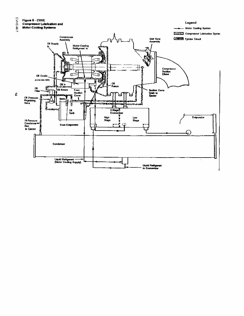
A schematic diagram of the temperatures may exceed 150°F (360-1250). Oil entering the oilcompressor lubrication system is on the compressor discharge, oil cooler assembly from the oil tankillustrated in Figure 5; this system
tank (heater), oil filter, and oil (via the regulating valve and filter)supplies oil to the compressor
lubrication lines. flows into a coil inside the coolermotor bearings.
shell. See Figure 6. As the oil
Oil is pumped from the oil tank(i . e . by a pump and motor locatedwithin the tank) through an oilpressure-regulating va lvedesigned to maintain a net o i lpressure of 12 to 18 psid . I t is thenfiltered and sent to thecompressor motor bearings . Theoil filter assembly is equipped w ithrefrigerat ion valves to isolate thefilter during filter replacement .
From the bearings, the oil drainsback to the oil tank through returnlines.
To ensure proper lubrication andprevent refrigerant from con-densing in the oil tank, a 750-wattheater is immersed in the oil tankexterior. Operating in response toa signal from the UCP, this heaterenergizes as needed to maintain140° to 145 OF (60-63 C) when thechiller is not running. When thechilleris-operating, thetemperature of the oil tank istypically 115° to 160° F (46-72 C).
passes through this coil, it iscooled by a mixture of gaseousand liquid refrigerant that surroundthe coil exterior.
Once the cooled oil leaves thecooler shell, it flows directly to theinboard motor bearing, andeventually returns to the oil tank.
Refer to Figure 5; notice that theoil tank is vented between thecompressor inlet vanes and thefirst-stage impeller suction cover.During normal system operation,motor barrel pressure is greaterthan that of the oil tank. Therefore,any gaseous refrigerant thatenters the motor bearing cavitiesis drawn toward the oil tank where
it is removed by the vent line.
A dual eductor system is used toreclaim oil from the suction coverand from the evaporator , anddeposits it back into the oil tank .These eductors use high pressurecondenser gas to draw the oil fromthe suction cover and evaporatorback to the eductors , from theeductors the oil is discharged tothe top of the oil tank .
Note: CVHEs utilize a circuitmodule control relay and solenoidvalve that temporarily close the oilsump vent line during the chillerstart sequence. This prevents theloss of oil pressure that can occurduring start-up by isolating the oilsump from the low-pressure cavityat the opposite end of the sumpvent line.
The oil cooler is piped into thereturn circuit of the motor coolingsystem. Part of the refrigerant thatis used to cool the compressormotor passes through the oilcooler shell on its way to theeconomizer.
Motor Cooling System
CVHE compressor motors arecooled with liquid refrigerant; seeFigure 5 for a schematicillustration of this pressurizedsystem.
Liquid refrigerant flows from thecondenser sump to the bottom ofthe compressor motor, Figure 7 ,where it enters the motor chamberthrough a control orifice . As thel i quid refrigerant touches thewarme r motor components , aportion of it flashes to a gas andcools the motor. Th is "flash " gas ,along with any excess liquidrefrigerant , then drains to thesecond -stage of the economizer .
Because of the positive pressuredifferential between the condenserand economizer, properrefrigerant flow through the motoris maintained at all loadconditions.
13 CVHE-M-7
< Fiyurs 6 - C1MEm Compressor t.ubrkattaf and
Motor-cooNrp SysOems^
CompressorAssembiy
of s+PDN , Motw•CuaMq\ Retrlgcrant In
ON Coder_
(CVNE 364 1 230 )
Oa
Fpar
CO Pfes Sl t!!- - ^--^Regulat^9 , F^i ^
of InOf";-.'.ie..Oi Return From
Sudlo^OWNFAtTv Cover
•^ . .. Oi lTank
Hi-RreswreCondertsr ,Gas From Eveponda
to E^edw
Condenser
Llquld Rdrlyerant(Mota Cooing Supply)
HighSta9e
ONReturn
4MM
YJet Vanebsimbly
Legend
-^- Motor Cooing System
Comprnsor LubrlcaGon Syslen
^ Ejector CkwH
CompressorSuWonEbow
Sudbn CoverOraIn toEjttlor
LOW Evaporator
^9a
Y
Liqdd A@M1pwantto Economlza

Figure 6CVHE/CVHF Oil Cooler Assembly
I "..:a
UquidRelriperantOut
OA In(hom Filter)
Od Out(to InboardBesrin9)
4532-2900-4 1
Figure 7CVHE Motor Cooling System
compressor orlRCeM otor
RelrigennlSupply to Oi Coolerfrom Molor
OA Coder
LiquRik{p t
a T.^ I--/
EconaNxx
Evnponlor
^Conda^ss9-P I
RekipaantRNumfrom Motor andoa Cooler
15 CVHE-M-7
Overview
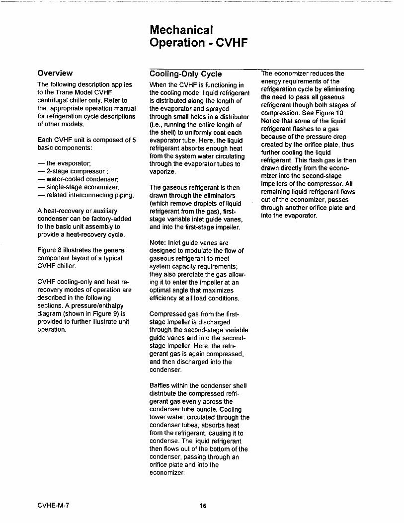
The following description appliesto the Trane Model CVHFcentrifugal chiller only. Refer tothe appropriate operation manualfor refrigeration cycle descriptionsof other models.
Each CVHF unit is composed of 5basic components :
- the evaporator;- 2-stage compressor ;- water-cooled condenser;- single-stage economizer,- related interconnecting piping
A heat-recovery or auxiliarycondenser can be factory-addedto the bas ic unit assembly toprovide a heat-recovery cycle .
Figure 8 illustrates the generalcomponent layout of a typica lCVHF chiller .
CVHF cooling-only and heat re-recovery modes of operation aredescribed in the followingsections. A pressure/enthalpydiagram (shown in Figure 9) isprovided to further illustrate unitoperation.
MechanicalOperation - CVHF
Cooling-Only Cycle
When the CVHF is functioning inthe cooling mode, liquid refrigerantis distributed along the length ofthe evaporator and sprayedthrough small holes in a distributor(i.e., running the entire length ofthe shell) to uniformly coat eachevaporator tube. Here, the liquidrefrigerant absorbs enough heatfrom the system water circulatingthrough the evaporator tubes tovaporize.
The gaseous refrigerant is thendrawn through the eliminators(which remove droplets of liquidrefrigerant from the gas), first-stage variable inlet guide vanes,and into the first-stage impeller.
The economizer reduces theenergy requirements of therefrigeration cycle by eliminatingthe need to pass all gaseousrefrigerant though both stages ofcompression. See Figure 10.Notice that some of the liquidrefrigerant flashes to a gasbecause of the pressure dropcreated by the orifice plate, thusfurther cooling the liquidrefrigerant. This flash gas is thendrawn directly from the econo-mizer into the second-stageimpellers of the compressor. Allremaining liquid refrigerant flowsout of the economizer, passesthrough another orifice plate andinto the evaporator.
Note: Inlet guide vanes aredesigned to modulate the flow ofgaseous refrigerant to meetsystem capacity requirements;they also prerotate the gas allow-ing it to enter the impeller at anoptimal angle that maximizesefficiency at all load conditions.
Compressed gas from the first-stage impeller is dischargedthrough the second-stage variableguide vanes and into the second-stage impeller. Here, the refri-gerant gas is again compressed,and then discharged into thecondenser.
Baffles within the condenser shelldistribute the compressed refri-gerant gas evenly across thecondenser tube bundle. Coolingtower water, circulated through thecondenser tubes, absorbs heatfrom the refrigerant, causing it tocondense. The liquid refrigerantthen flows out of the bottom of thecondenser, passing through anorifice plate and into theeconomizer.
CVHE-M -7 16

Figure 8General Component Identification - Trane CVHF
Compressor
Hot Gas BypassValve (Optlonal) .
PurifierPurge
Condenser_r4-
Econom izerVapor Out
Condenser
L iquid Out
TerminalBox
Elbow
Rupture Disc'Connection
(3" NPTE)
-Unft ControlPanel (UCP)
Front VNw mow
SuctioncO1^p1mtar TamY^al
Bbow 1 B^x
Cond. I\ I I 1 fl I a
RuphnoConnettbn
(^ N^
Dbc
Urwt CarrdPand (UCP)
Evsporata
17 CVHE-M-7

Figure 9CVHF Pressure/Enthalpy Curve
Figure 10CVHF Economizer Operation
Liq u id Refrigera n tIn Economizer
Economizer
Inlet Pipe
P3 5 Condenser
aPz 6
Economizer
dC- P^
1X Evaporator 2
Enthalpy (BTU/LBM)
4 Compressor^ (2nd-Stage)
3 `T
Compressor(1 st Stage)
CVHE-M- 7 18
O r if i ce From Condense r O ri f ic e To Evaporato rP late P late

Compressor LubricationSystem - CVHF
The CVHF compressor lubri-cation system, which supplies oilto the compressor motor bearings,is illustrated in Figure 11.
Oil is pumped from the oil tank(i . e ., by a pump and moto r locatedwithin the tank) through an oilpressure-regulating valvedesigned to maintain a net oilpressure of 12 to 18 psid . It is thenfiltered and sent to thecompressor motor bearings . Theo i l filter assembly is equipped withrefr igeration valves to isolate thefilter during filter replacement .
From the bearings , the oil drainsback to the oil tank through returnli nes .
To ensure proper lubrication andprevent refrigerant from condens-ing in the oil tank, a 750-wattheater is immersed in the oil tank.Operating in response to a signalfrom the UCP, this heaterenergizes as needed to maintainan oil tank temperature of 140 to145 F (60-63 C) when the chiller isnot running. When the chiller isoperating, the temperature of theoil tank is typical 115 to 160 F(46-72 C).
WARNING: tually returns to the oil tank.
Use caution while working onThe refrigerant-side of the oil
certain areas of the unit. Surfacecooler is piped into the return
temperatures may exceed 150° Fcircuit of the motor cooling
on the compressor discharge, oilsystem. Part of the refrigerant that
tank (heater), oil filter, and oilis used to cool the compressor
lubrication lines.motor passes through the oilcooler shell on its way to the
The oil tank is vented between thecompressor inlet vanes and thefirst-stage impeller suction cover.During normal system operation,motor barrel pressure is greaterthan that of the oil tank. Thereforeany gaseous refrigerant thatenters the motor bearing cavitiesis drawn toward the oil tank whereit is removed by the vent line.
economizer.
Motor Cooling System
CVHF compressor motors arecooled with liquid refrigerant. Thispressurized cooling system isillustrated in Figure 12.
A dual eductor system is used toreclaim oil from the suction coverand from the evaporator, anddeposits it back into the oil tank.These eductors use high pressurecondenser gas to draw the oil fromthe suction cover and evaporatorback to the eductors, from theeductors the oil is discharged tothe top of the oil tank.
Note: CVHFs utilize a circuitmodule control relay and solenoidvalve that temporarily close the oilsump vent line during the chillerstart sequence . This prevents theloss of oil pressure that can occurduring start-up by isolating the oilsump from the low-pressure cavityat the opposite end of the sumpvent line .
Liquid refrigerant is used to coolthe oil supply to the inboard motorbearing. Oil entering the oil coolerassembly from the oil tank (via theregulating valve and filter) flowsinto a coil inside the cooler shell.As the oil passes through this coil,it is cooled by a mixture of gase-ous and liquid refrigerant thatsurround the coil exterior. Oncethe cooled oil leaves the coolershell, it flows directly to the in-board motor bearing, and even-
19
Liquid refrigerant flows from thecondenser sump to the bottom ofthe compressor motor where itenters the motor chamber thr.ougha control orifice. When the liquidrefrigerant contacts the warmermotor components, a portion of itflashes to a gas and cools themotor. This "flash" gas, along withany excess liquid refrigerant, thendrains to the evaporator sump.
Because of the positive pressuredifferential between the condenserand evaporato r, p roper refrige rantflow th rough the motor is ma i n -tained at all load conditions .
CVHE-M-7

Figure 11CVHF Motor Lubrication
Left End View
rw to.Mous i n0
NI-I
S l eeve 6eor inyO i l Supply
Vent L i w•So l eno i d Vo lv o
O i l Tank
lorPressureE duc to r L in e
Evapo r a t o r
Conqr ossorMouN i ny
O 11 F111 s r
O i l Relu r nTo Tenk
/ HI-Pr^ssureGas Supp i yTo E j e ct o r
Condense rO i l Cooler
Back ViewRss tric to rF i tl i nq
Thrua t 8earin yHo u s i ng
O il SuOP I Y -1 ^
^
Oil Returnto T ank
^
O il Fllt s r
Ca n d snse r
O il Tank
Fvooo r alo r
CVHE-M-7
Rost ri ete rF i tt i ng
Thrust Beor l npOil Supply
Sl ee v e BearingO il Supp ly
Oil Tank Canp r essorVe nt line Hou s i ng
r '
20
Vent L i neSoleno i d Volve
Oil ReturnTo Tank
Suct i on CoveI Dra i n To^ E j e c t or
Oil Cool e r ;

Figure 12CVHF Motor Cooling System
Left End ViewCompressorHous1n9-.
MotorHousiny
Refrigerant from-motor to oU cooler
OA Tank-
Of Cool
Back View
Refrigerant frommotor to of cooler
Refrigerant frommotorto evaporator sump
oa coaer
Evaporator
R efrigerant re t urn toevaporator from motorand of cooler
MotorHousing
IL-
21
0
Uquid refrigerantto motor
CondenserSump
Refrigerant return toevaporator from motorand of cooler
CompressorHousing
Liquid refrigerantto motor
Condenser
CVHE-M-7

Free Cooling Cycle the evaporator and floods the tube(Optional)- CVHE/CVHF bundle . See Figure 4 .
Based on the principle thatrefrigerant migrates to the coldestarea in the system , the freecooling option adapts the basicchiller to function as a simple heatexchanger . However , it does notprovide control of the leavingchilled water tem ratu r .
If condenser water is available ata temperature lower than therequired leaving chilled watertemperature, the operatormanually stops the compressorand starts the free cooling cycleby enabling the Free cooling modein the "Operator Settings" Groupof the Human Interface.
Several components must befactory-supplied or field-installedto equ i p the unit for free coolingoperation :
- options module 1 U5- a refrigerant gas line , includingan electrically-actuated shutoffvalve , between the evaporator andcondenser,
- a valved liquid return line,including an electrically-actuatedshutoff valve, between thecondenser sump and theevaporator;
- a liquid refr igerant storagevessel ; and ,
- additional refrigerant .
Since the temperature andpressure of the refrigerant in theevaporator are higher than in thecondenser (i.e., because of thedifference in water temperature),the refrigerant in the evaporatorvaporizes and travels to thecondenser. Cooling tower watercauses the refrigerant to con-dense, and it flows (again, bygravity) back to the evaporator.
Th is compulsory refrigerationcycle is sustained as long as atemperature d ifferential existsbetween condenser andevaporator water . The actualcooling capacity provided by thefree cool ing cycle is determined bythe difference between thesetemperatures which , in turn ,determines the rate of refrigerantflow between the evaporator andcondenser shells .
If the system load exceeds theavailable free cooling capacity, Ug
operator must manually initiatechangeover to the mechanicalcooling mode by disabeling thef= cooling mode in the"Oep ratorSettings" Group of the Human
Interface. The gas and liquid linevalVes then close and compressoroperation begins. Refrigerant gasis drawn out of the evaporator bythe compressor, where it is thencompressed and discharged to thecondenser.
When the chiller operator initiateschangeover to the free coolingmode, the campressorwill shutdown if running, the shutoff valvesin the liquid and gas lines open;UCP (i.e., unit control panel)control logic prevents the com-pressor from energizing duringfree cooling. Liquid refrigerantthen drains (by gravity) from thestorage tank into
Most of the condensed refrigerantin it i ally follows the path of leastresistance by flowing into thestorage tank . This tank is ventedto the economizer sump through asmall bleed line ; when the storagetank is full , liquid refrigerant mustflow through the bleed line restric-tion . Because the pressure
CVH E-M -7 22

drop through the bleed line isgreater than that of the orifice flowcontrol device, the liquid refri-gerant flows normally from thecondenser through the orificesystem and into the economizer.
Note : During changeover fromfree cooling to mechanical cooling ,the refr igerant transfer process iscompleted within 3 minutes . Themicro-computer- based controlsystem prevents carry-over by notallowing the unit to load for aperi od of two mi nutes .
Heat Recovery Cycle(Optional)
"Heat recovery" is designed tosalvage the heat that is normallyrejected to the atmospherethrough the cooling tower, and putit to beneficial use.
For example , a high-rise officebuilding may require simultaneousheating and cooling during thewinter months . With the addition ofa heat recovery cycle , heatremoved from the building coolingload can be transferred to areas ofthe building that require heat .(Keep in mind that the heatrecovery cycle is only possible if acooling load exists to act as a heatsource . )
To provide a heat recovery cycle,a heat-recovery condenser isadded to the unit; see Figure 2.Though physically identical to thestandard cooling condenser, theheat-recovery condenser is pipedinto a heating circuit rather than tothe cooling tower.
During the heat recovery cycle,the unit operates just as it does inthe "cooling only" mode exceptthat the cooling load heat isrejected to the heating watercircuit rather than to the coolingtower water circuit.
When hot water is required , theheating water circu it pumpsenergize . Water circulated throughthe heat-recovery (or auxiliary)condenser tube bundle by thepumps absorbs cooling - load fromthe compressed refrigerant gasdischarged by the compressor.The heated water is then used tosat i sfy heat ing requirements .
Auxiliary Condensers(Optional)
Unlike the heat-recoverycondenser (which is designed tosatisfy comfort heatingrequirements), the auxiliarycondenser serves a preheatfunction only, and is used in thoseapplications where hot water isneeded for use in kitchens,lavatories, etc. While the operationof the auxiliary condenser isphysically identical to that of theheat-recovery condenser, it iscomparatively smaller in size, andits heating capacity is notcontrolled.
Trane does not recommend
ope rat i ng the auxili ary condensera l one because of its small s ize .
2 3 CVHE-M-7

Unit Control PanelSafety and operating controls arehoused in the UCP 2 unit controlpanel, the starter panel and thepurge control panel (Control Panellayout is illustrated in Figure 13.)
The UCP2 control consists of amodular design partitioned bymajor function or group offunctions. All modulescommunicate with each other thruthe IPC circuit.
Figure 13UCP2 Control Panel
Chiller ControlSystem
Major components w ithin each of The "microcomputer-based "these control groups are modules are described below .described below . All wiring to the modules are to
pluggable terminal blocks .Unit-mounted temperaturesensors, pressure transducersand functional switches provideanalog and binary inputs to the
various modules.
X13650485C
CVHE-M-7 24

Chiller Module (1 U1)
The Chiller Module, located in theUCP2 control panel, is the Master-of-the-Chiller communicatingcommands to other modules andcollecting data/status/diagnostic
information from other modulesover the IPC (Inter Processor
Communications Link). The Chiller
Module performs the LeavingChilled Water Temperature andLimit Control Algorithms arbitratingcapacity against any operating
limit the chiller may find itselfworking against. the Chillermodule contains non-volatilememory both checking for validset points and retaining them onany power loss. Inputs andOutputs are chilled water systemlevel I/O including evaporator andcondenser water temperatures,outdoor air temperature,evaporator and condenser water
pump control, status and alarmrelays, external Auto-Stop,emergency stop, externalcondenser heating (heat pump),
evaporator and condenser waterpressure drops and evaporator
and condenser water flowswitches. Connection points ofstandard and optional inputs andoutputs for the chiller module
(1U1) are shown in Figure 14.
25 CVHE-M-7

Figure 14Chiller Module - CVHE/CVHF
zo7-< I969
_ 2- COMM LINK FRWm tU2 JI - I . T
92 0a
(L ^uES i< J. 1sa) 1998-
-!4COMM L I N K GROM PI C
^ ^O -- 10 31t J, - I . Z ^(LINE S 10, ]1)
-21-
Co
.. UNK FROM P16102VIJt - 1 . 3
2 Z _ (LINES 15 . 16)
r2 1 3 - ^
zu -
R T'
215-
z i s -
4.1
z+s - ^
2 20-
wiCHILLER M ODUL E
• s
I 1
+ A IOMFN PLI IG 24 yA4t 2_ 8= UPPER PLUG
C 0J1 IN iER-PROCFSSOR J2
S 1 +COwwl/NICATpN
Zs vAG
4 4 - C^ L OWER PLUG IO WRLE)
D- UPPER PLUG iO STARIER)
i b
J4
EVnF EN TER I NG WATER TEMP
EYRP LEpNNG WATER TEMP
J3
ca+o E N TERING WATER swJ'.
COMD LEANNC WA TER TEMP
221 -
E%TERNAL AVTO -STaP
222- L - - - - - - ^ 2 (1ERM I k 2 MUS I BE
P5
JS JUYPEREDIF
NOT USED)
N ^so-sz 6Q^ 223 - ^ - ) }
1 EUERG[ NCY S TOP
2 2a - L------ ? y (hRY3hA W5T8E
JJU a[REO I F NOT USED)
zzs-PSC > s
APOMOED BT iRN1E ouroaors Nn reucN S*4LED
INtu[ fKLO
6AMBIE NT CMR
2 26- ))
z-- P7 > s J7
r n[nr vuuv coNma
228 - L - -- -P9A
z29 _ PED
2 30 - ^
2J 1 -
23 z
Nl^dr
z33-
`"o ^o P96
23 ^ -
2 35 - ^
. s mc236 - ..j
]]J]-
23B-
J 18
J20
Lo]
^
^-
CON I AC T FAPNGS
288 Ixoucnvc(_noNAL) i/3 NP .
}
Evav EX T i L`m wiR PRE SS
J9 ElO 1NPUI J26
(OPTIONAL) ovro iHa^r J28
CON D ENT h l^ WiR PRESS
(v+E ^sa J
21 A _
=2H
EVAP wiR naE 55 SOIEHqD(REQ / wA iER ^YSS.oiF,)
'6
2 Z A COND WM PRE 55 SOLENpp
(RE O W/ WATER GRFSSUI f
iis vacisnasiouea ^owoco--'^
P12 I
sK^CH I I LED WATER PU M P REI A Y
(OV nIX1/. L)
Sk1_ _ _ _ _ _ _ _
V- -_ _ _ _ _ -4 CONO WA TER PVMF REIFY
(REW IREO)
Pi6
COMG R11 NrvI nC RELAY(OV l10NAl )
P^8 --- ---1_---- -------- _ _ - _
-'^^\S^ I ALARM REL AY
__________ ___ JI f`__-_ i^OV110N .LL )
P20 J I
sKS_____ _________________ --'"J LIM IT WARMNGRELAT
(01 l 1ONAL)
' ,
^ [HiLLEO Wn IER FLOW StX ^CN
- -O^ o- ^•^ ^•^ ( REWIaED)IS
_^o- - ^ ^.L-^j
COUD WA TER FLOW SMO iCM8 I (RE WIR ED )
TO i T61-3
( SEE I I N E 1 5')
Y I xy1
FROM 1G83 (SEE ONE 266)(SE E LI NE 1 4 2)
CVHESW-4013G
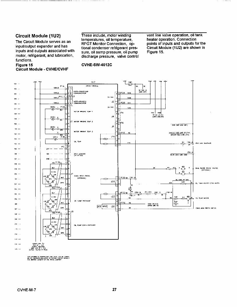
Circuit Module (1 U2)The Circuit Module serves as aninput/output expander and hasinputs and outputs associated withmotor, refrigerant, and lubrication,functions.Figure 15Circuit Module - CVHE/CVHF
144 -
145 -
IK
147
Ib
I a9
150
1 51 -
SI -
1 53
154 -
t55 -
t 56
15 ) -
ISB
159
I60 -
16 1 -
161 -
163 -
-1 64
65 -
Ififi
16 7
1 68 -
169
1 )0 -
1) 1 -
I2 -
1 1a - COMM UNN TOIUt Jt - 1.2
NI DN IV52^r^1(LI N ES 1B2.1B3 I I REO)
MR pi AWNG IS VROVRE IMY /Jq SM ALL NOT BF CORED
OR I15 CONIEM IS p 5CLO5ED TO OuRYIE V/JtMS wMWT
THE 'MiIT1EN Cp15ENT OF ME IWAME CWVAM Y
These include , motor winding vent line va lve operation , oil tanktemperatures , oil temperature , heater operation . Connect ionRFGT Monitor Connection , op- points of inputs and outputs for thetional condenser refrigerant pres- Circu it Module (1 U2) are shown insure , oil sump pressure , oil pump Figure 15 .discharge pressure , valve control
CVHE-SW-4012C
vEn T LINE SOLEnqO
DUAL F IL TER IPANS YAlVE S
(OP PONR I)
pL T ANK HEATER (150 WA TT)
Ol PUMP MOiqi
COND H I GH PRE SS S MITC H
CVHE-M-7 27

Stepper Module (1 U3)
The Stepper Module drives thestepper motor Inlet Guide VaneActuator on CenTraVac Ch i llers .The Stepper Module rece ives fromthe Chiller Module the d i rectionand distance to drive the inlet
Figure 16Stepper Control Module and Clear Language Display Module
,,, -,,,
-1 23
1 3^ -
1 2! -
1 ^ -
m -
^x -
uz -
1]] -
IN ^
I J^ -
^ M -
-1 37
iM -
^W -
wA2MDQIS Wlt^qIpSCMRGT 41 [LEGMC POK^, ^uowc W.ort ascw.ccrzBEI011[ SpeuONG
aREFix CODE ;-I 2. Dt=1µ`.=71= MA I N CON TROL PANEL
uVIEPIE°R °E""
2 = STARTER PANEL a AVERTI55EMENTVa.ua . .v.au.
3 P U RGE aco.xicc +cz rou+cs as saras4 U NI T M OU N TED DEVICE LC01M° '^s '"a u.+. +'c s
asaonc•cu^s anHS . a s*...c[o csr^ c nx. i c. r.i "w
5 PROVIDED BY OTHERS ^.u^cElEC
a xca.KC+n u. wuKc1wi0U[ ^vu^1 0ERLCNC^DASHED LINES INDICATE WIRING By OTHERS ^CMAErI[N IEUT CM1RUwEM DES
RlSSNRi CO^ORLLl1 Y^O^CSOU lA Yd1T
c a Ma Po^rt a^^MYO^Ea
sIEVVEn uoraavAN[ 1C NATpi
cvHE-Sw401 2c
guide vanes and then generates gerant temperature , bearingthe appropriate signals to oper- temperatures , compressorate the stepper motor. The d ischarge temperature , in l et guideSteppe r Module has inputs and vane binary posit ion indicatoroutputs used to support functions (B . P . I . ) , and saturated condenseron the stepper module . These in- refrigerant temperature .clude saturated evaporator refri- Connection points of inputs and
outputs of the Stepper Module(1 U3) are shown in Figure 16 .
It 1 .
CVHE-M-7 28

Options Module (1 U5)
The Options Module providescontrol or interface requirementsfor a number of options. Featuressupported by the options Moduleinclude Ice-Making, Heat
Recovery , External Chilled Water Tracer Temperature Sensor, HeadSetpoint , External Current Limit Relief Request , MaximumSetpoint , Free Cooling , Capacity Relay , and TracerEvaporator Differential Water Controlled Relay . Connect ionPressure Drop , Condenser points of inputs and outputs of theDifferential Water Pressure Drops Option Module (1 U5) are shown inPercent RLA of Compressor, F igure 17 .
Figure 17Options Control Module CVHE/CVHF
256 -
35^-
260-
'.5< -
266 -
2457
2>z1» -
2le -
zis-
^^wI V 2 JI - S . 4
(U^'CS14 ].
1 aA)
,IJ5
OPnp+S uODU L E
J t i N rt a-enoccssoaca1uuNIc A no rv
2 1 vnc
AV% NEAi PE C ENi J ;
P38
AV% HEAi NEC LEAK
> .
P 3C3
^- - ^-^ - ; sEXT F C S M iCM
L----- e
P3oICE uPKirvG
L _ _ _ _ - - IT
na ua 1- .erz PSP..>
F C ACNaTqt CLOSED
2
.nrcss. P56 »JS
-W [aEvnP pii - i£A vaESS
z- io v a+ - - -
P76z-io v oa
7CE_--^---L-------
P7 DQ - f0 V OR
P9Ao - 1 o
+R
HE ^i RECO^ERTACN ^ TOR
fAIA C OMPFESSOR
J7
(onocr+ w% m^c[a^R
Exi CURRENT l i uil 5[iPqv!
Ex r CHI LL ED wm scroa x r
J9
cwo oi F WATE R PRESS
3. vAC
J8
J f 2
J14
J 1 6
J 1 8
S10AIER PPCM]ED
P2 u:° ns v. c is + ^
i:-- I
I( l ^ N[Sll2^]
P2)
IC ^ ^ I
^----- ---^ ------- ------- ic[uar:wce[ur
P12 I I
SK7- - --------------[[^----- -.J H E MRELIEFFEWESiRE I Ar
P 1 4 _ _ _ _ .-1 I
- _ - ^_ - _ _ _ _ _ _ _ __ Il __ _ _ _ _ _ - YAZ i u tl u CAFAC iT Y FEL/. T^
---
I T 4P22AOAAIER
OaEH2
Fie
-^1 - _ _ _ - TRA C ER COM IR0.LCD AE L Ar-------------^LI°
p20
- - - - - - - - - - - - - - - - EE L00. i NC AUK A[ L Av- ^
P ? < s ^ s • nou
11
3 Ih ^EE COOUMG aCNniOqZ ^B t ] z ^u [nv /Z
IG>5 LiuE vAL y[7
n e ov[v
ca+.^'ccrsOaE SEV a( ^o
1 AVERTISSEMENT..cc "
o c c a. ^. ccrc z^ rw^cs i cs swxccsELL
.roRcic 'rt sµv`iusT• -< c_
wrt a ocoEr1icnin^'
i' ""EWi aLFS ES COUVOUEL LSAXEaE55
1N 1 W if^FN CM .F M 1 C^ n( ^Ip^N [ CWr ^H r M'^^W ^
PrzEFixCODE
1
-
MAIN CON T ROL PANE L?
-S TAR T[R PANE L
3-
PURG F4 = U PJI i M OU N TED D EVI C E
= PftOVIpFD BY OTI I ERSUA`d iEG U N ES INDICATE WIRI N G BY OTHE R S
CVHE-M-729
CVHE-SW4014B

Starter Module (2U1)The Starter Module located in theCompressor Motor Starter Panelprovides control of the starterwhen starting, running andstopping the motor. The StarterModule provides interface to and
control of Y-Delta , X-Line ,P- Reactor , A-Transformer , andSolid State Starters ; interface toand control of Adjustable SpeedDrives is also supported . TheStarter Module also provides pro-tect i on to both the motor and thecompressor in the form of start-ing and running overload , phase
Figure 18Starter Module - CVHE/CVHF with Remote Across the Line Starter
^e -
;o =
^9-
SFE xoh ♦
reversal , phase loss , phaseunbalance , momentary powerloss , and compressor surge .Typical wiring connections to thestarter module are shown inFigure 18 and 19 . See "as built "wiring diagrams that ship with theunit for specific details and troubleshooting for the type of starter onthe unit .
^--
^^^ T3 ^B ^ C us^+E SSrn
aw
^(uNCS z io . zi+l fi
ZU7
S i nc i [F -7
T P1
euc ^ ^ cwu^.^c.n«.ssa+
P3A
PN (^ n^µYJLR
P 38II rI , s J 3
vH s c e -c vars(oanauU
P3C-
c- . vo^rse f or n a+.U
2ro • P$A PHASE A CU-r
J5^ n o • P SB -.sc e cuaac N r
BRN BU(
z iR PS C RH• sc c cua rsE x r
• 3! !
-TE A0+055 ME L IM E Si ARI[a
va[nt Op[.. cama v .r^aI
s*.ni c v A Raa - wn¢
u .ur uw^rzo o[wc[5 - w+aNDFD Br OMCASo+sHco u.c s wyurt r.m r^ c e r oMcm
^ • -tl^ v. r
xx
xz . vnc J2 P2
1A «=-^a^: m-z
CER,lBl-^ ' 10^
.L^
IT IGRESS 'SiCNS5^
I-o-
uc LIRc
„RI-, scc RoTc ^ 6re,- a
^
Cm hovx Sey u m c e o l O pe^a^^m ^ ^ n R-4u E Slo^ in
8WARN IN GWoPIS '.0. *-!
6 AVERTISSEM ENT
aciwa^.`.caECHa`^u^s^ssKis'
L,yI MPO R TANT
xortsovnauu srARrtA wrtniax scc si.whn
.wUf1C1UN E2 M PI HG pAGV Au 10R SVCCiIIC
MPL< A T pl
UN L E 55 OM FANY N rt
SMOM A T 25 C (JI f ). P
EPE ESSUUE . A T 50x R[ LiiAE NUU iDrv. Vn i N
• LL UMI TTC S NxNEO OR AuD /.FiFn /.
wORUK SMI IpOVM HAS OLCU R EO
s. r+uuecns Xa+c mc mwr voc oF TMc -U.ncocvcr..re THE ta.nw or THE ca+T.crs e.lWE NMBEN M1 UIWE PUNE D NU UKq INpGh S• HqtuMLY 0.p5CD COx f .fTHR
EE VHAY VORER SUGV L Y V 0. f 1GE -SEE Uw f rv AuCPLnIC
5 FEM OIE ACCRO55 ME lWE sfM rtP MtMNt e E TMECN
SfM2X AND SIAP IER YOpAE AR E SNOW Y ESTM TE n u .wUfAC T I RES vluwG pR U+w F OR
YEGY i G SIAFIEF wRWG.
LA CpLS HE xOi SNOww . C
C
OR frtq.LED
Bv M[ IOGIC 0 E ME uICpO-COU i1 i IXA[F YE
YWENCC Of OPCP AI IO U
P0.-
tt uAPxWL pl ME GUN E M! mnN SGORU E F uU1 1 9E
f- iOVNroS TH E i NCOU i NG CUHFENI .
Sz. s . arewz . c*a+
^ iB ^- ^^
•
CVHE-SW-4000C
CVHE-M-7 30

Figure 19Starter Module - CVHE/CVHF with Factory Mounted Wye-Delta Starter
,6 -
e - u
^o -
^ b
17
I B -
i9 -
]0 -
1 1 -
25 -
27
3 9 -
)5 -
]6 -
^ IoR ,
_ ............ _ .. ^ . _....._ _ ..._...._. _. _ __ -
CL^G^ i^ pN
} UNl[ 5 5 01HEA^ S C MO 1ED . ^LI S ^ M IGMCS P F E
* 1 25 c l» rl. r. . nosvH^mcPa[SSUP[ .
A
1 S O R "nKHUUi p 1Y . W
A LL Un L 1'I E S IURHE^ O^t P^+D R-F A
Nou u ^i vwroorn+ H ^s acuaco.^. uuuorns n^a+c Mc nirN* voc ar r.e sc^cu.^ic
ocvcr+ . rt n^c i« . non or n4E ca+ uc*s BYiwc wuue, .. ur+ocaiwco uu uoca woic + rzsA Nprueur uouo cWAc*.wce . ;e vo»te suvviv va* . cc-sec u^^* eweouicZ.
ecTMCC^.sTnarca
ANDca+1 aa.^ uaaK[ ARE sNOM++. sc[
StALRF u faC illaES 'MP i uG OiAGPAM f Oq
-C1 1 1 f. -aT[a vnHiwG
R f.L P T C-, AHC NO I 5110^ . - IPC 3 AFC C-OL LC D
B '/ *l O I C V 1 w1 C aO - C ONTA0.LEF SEE
Sf^U f r iC C 0 ^ - PP nON
T 1 E NA R[N i INANY OHU[R uU 5 1 BE
O wna L: lI1E 1NCOU ixG CUAA CNi
" .....__..___
W5 V0. 1 u'. C•
IX^ NE C ! ^lL E L t a^ ^ vqciuoiNC nc.a+c oscoNi+c*sB EVM E 5
NSCp+rKCi vOrTR
9C%C XAMGt^G G ^^ EAUSEE Ka50N A L -P V OR pE
CP AVERTISSE M EN T.nocun
o«o..cc_ .wrts ics saunusC 1vKK 1E5 I wCIUAM i L E S
rzToc occ-nn u swua
aEOCswacz^ca+vuuc ui^xVcncs
W^ lm
y1MPORTAN TUSE
R[^PE N CvuCr1i
0 R5 WL1
^ CiIXi
iCA
1w iRCiW
CW II.Cipt
CVHESW-4008C
31 CVHE-M-7

Purge Module (3U1) outputs to control the purge, Processor Communications Link)
The Purge Module provides optimizing both purge and chiller uploading set points and down
control of the Purge used onefficiency. The Purge Module loading data and diagnostics.
CVHE and CVHF units. The Purge resides in the purge control panel Connection points of the input and
Module provides all the inputs and and communicates with the Chiller outputs to the Purge Module areModule over the IPC (Inter shown in Figure 20.
Figure 20Purge Module - CVHE/CVHF
a, -6! -
6! -
66 -
6l -
6! -
6V -
72 -
l 5 -
l6 -
oe -
ex -
s. -
es -
m
ee -
3U1
Pi
GU wGE 4 0DULE
):1 1 +
e^ J1 w rtn-vnacsson^ _ _ cauwra c/.np^
J3A
aHnue SA T ca+o hur(BEmo-nr anh
2 J38
we¢ arcr couo> , wcnoN a.o
J3C J3>s
uano uyc1 sf.sw
6
30yJ3D
3N5[RNC( GUYPCUT
s. ra
P REFIX CODE1 = MAIN CO N TR OL PANE L
2 = STARTER PANEL
3 = P U RGE4 = UNIT MOUNTED DEVI CE5 = PROVIDED BY OTHERSDASHED LINES I NDICATE WIR I NG BY OTHER S
MW 1f9
1-3L;:R' «.^ -)1[ . D 2OA . ♦
ITS VAC FROM G OMTM0. PAl1 E L
J ^ B f-i .)0 0 A JOt ♦ -
ll L 2
SODB . C 1j ]O^ B
2 P2 39I2.
vec J2
J 4
J6
J1 0
J 1 2
eix
^ooc
9lK
0 ^ y.1-z
Jo..
Soo[
xs KEXHAUST v.iYc sacNao
uNK VAI VE 50.EHq D
J 1
pUar, [ aFGi CO Na+C55dA
B^ ll,^^^ pUnG[ PUUP-WT GOUOp[SSOR
P 14
,"v.c
".
I N51puEN va0HDE0 1
Pt 6
--__----------------.-e 'na o- ^ ^ ueu nru r_u_ sos ^- I_ _ - ^ (ronwk l
'---------- - ----------- -r--P 26
rxw s*.A*cr+ au.+ c-c *o» .u .
__________________________J COUvrtE55qtRJMNiHG(NElNO-fIT DNLT)
BWARNINGN.z^noous var^u!
CLUdwG R[uOfEqSGMMECSNBEiORE SENNCIHG
ec^wc s^Hcr^iciirCi'ius^cR5[KaE PERSONAL ^„ r OR OE^ *N .
^AVERTISSE M ENT-Ac[ w • s.uixun.
EC^d1E5wGLUUiiElCSw ^SJCMC
DCiFCCR IEnS I 'CNmF^CwE
^^urt o[ occwutcrtrt LA saunccELC Gf
H`UE AV
r0ifECR1ER
t 'FNmC T [N cEViCNmAwEn DESSSUnES CqRvOR[ll[5 SEKn[5
W L . W.
CVHE-SW401 a..
CVHE-M-7 32

Clear Language Display The front face of the ClearModule(1 U4) Language Display Module
consists of a LCD Display, anThe Clear Language Display LED, and a keypad. The LCDModule, located on the UCP2 Display presents the operatingcontrol panel door, provides status of the unit, operating setdisplay of chiller data and access points,operating conditions, unitto operator/ serviceman controls, configurations, purge operatingset points and chiller setup conditions, service test, unitinformation. All information is configuration, and diagnostics in astored in non-volatile memory in clear language display. The LEDthe Chiller Module; the Clear is red and will only be "ON" whenLanguage Display and the Chiller a manual reset is required toModule work together to display restore the unit to full operation.and store information requiring The keypad has 16 keys arrangednon-volatility. The connections to in a 4 x 4 matrix.the Clear Language DisplayModule (1U4) are shown in Figure21.
Figure 21Clear Language Display Module -
0Auer
SUeu RepM ('youP
SNeCf Sealllys OidiP
^O^
Mto
0 TRANE "
CVHE-M - 7 33

Operator Interface
All operator interface is throughthe keypad/display on the front ofthe unit control panel as shown inFigure 21. The keypad consists offour selectable Report Groupkeys, four Settings Group keys,six keys to change setpoints, unitconfiguration and variables, theuto key, and the top key.
Report Group Keys
The four Report Group keys forCVHE/CVHF units are:
- Custom Report Group- Chiller Report Group- Refrigerant Report Group- Compressor Report Group
Selecting and pressing a ReportGroup key will display, the headerdisplay for that Report Groupshowing the title of the ReportGroup and a summary of thereports in a Report Group.
The NEXT and PREVIOUS keyscause the display to step throughthe displays in a Report Group.The Report Group display willwrap around top to bottom as thedisplay is scrolled through thesequence using the NEXT orPREVIOUS keys.
Custom ReportThe Custom Report Group can beprogrammed by the operator andcan contain a maximum of 20reports . To add a report to theCustom report Group , pressthe + key when the desiredreport is being displayed from itsnormal report location . To removea report from the Custom ReportGroup , press the Q key whenthe desired report is being dis-played in the Custom Report
Report heading :
L Us e r De f i ne Custom Repo r t
V Press(Next)(Previous)to Continue
Followed by selected reports . If noreports are selected to be in theCustom Report Group , the secondentry is :
See Operators Manual to se l e ct ent ri e s.
Chiller ReportThe Chiller Report Group Sequence is a follows :
Report heading :
Chiller Status, Wtr Temps & Setpts
Press (Next) Previous) to Continue
Chiller Operating Mode
Friendly mode line 1
Friendly mode line 2
Friendly mode line 1 is indicativeof a unit mode . Friendly mode line2 is usually a verbal continuat io nof line 1 and can be viewed as aconti nuous message along withli ne 1 . In some cases Fr iendlymode line 2 is the display of anassociated timer or systemparameter .
[ Friendly mode] will be one of thefollowing :
CVHE-M-7 34

FRIENDLY MODES
FRIENDLY MODE (First Line/Second Line)
Display is Blank
Resetting
Local Stop: Cannot be overridden by
any External or Remote Device
Remote Display Stop: Chiller may be
set to Auto by any Ext or Rmt Device
Remote Run Inhibit From Remote Computer
Remote Run Inhibit From External Source
Remote Run Inhibit From Tracer
Heat Sink Temperature Start Inhibit
Diagnostic Shutdown Stop
Diagnostic Shutdown Auto
Auto
Waiting For Evaporator Water Flow
Auto
Waiting For a Need To Cool
Auto
Waiting For a Need To Heat
Waiting For Tracer Communications
To Establish Operating Status
Starting Is Inhibited By Stagered Star:
Time Remaining: MIN: SEC
Transitions To Free Cooling
Waiting For Cond Water Flow
Opening Free Cooling Valves
Cond Water Is Flowing
Closing Free Cooling Valves
Unit Running: Low Evap/Cond Diff Limit
Time Remaining To End Of Limit: MIN:SEC
Transitioning To Free Cooling
Waiting For IGV Positioning To Complete
Unit Is Free Cooling
35 CVHE-M-7

Starting Is Inhibited By Restart
Inhibit Timer: Time Remaining [Min: SEC]
Establishing Cond Water Flow
Establishing Oil Pressure
Establishing Cond Water Flow
PreLubrication - [XX] Sec Remaining
Establishing Cond Water Flow
PreLubrication - [XX] Sec Remaining
Cond Water Is Flowing
Establishing Oil Pressure
Starting
Unit Is Running
Unit Is Running
Capacity Limited By High Current
Unit Is Running
Capacity Limited By Phase Unbalance
Unit Is Running
Capacity Limited By High Cond Press
Unit Is Running
Capacity Limited By Low Evap Temp
Unit Is Running
Capacity Limited By Vane Open Travel Stop
Unit Is Running
Limited by Capacity Limited By Vane Closed Travel Stop
Unit Is Running
Unit Is Running In Surge Condition
Unit Is Running
Capacity Limited By Pulldown Rate Based Soft Loading
Unit Is Running
Capacity Limited By Current Based Soft Loading
CVHE-M-7 36

Unit Is Running; Hot Water Control
Unit Is Running; Hot Water Control
Capacity Limited By High Current
Unit Is Running; Hot Water Control
Capacity Limited By Phase Unbalance
Unit Is Running; Hot Water Control
Capacity Limited By High Cond Press
Unit Is Running; Hot Water Control
Capacity Limited By Low Evap Temp
Unit Is Running; Hot Water Control
At Vane Open Travel Stop
Unit Is Running; Hot Water Control
At Vane Closed Travel Stop
Unit Is Running; Hot Water Control
In Surge Condition
Unit Is Running; Hot Water Control
Pulldown Rate Based Soft Loading
Unit Is Running; Hot Water Control
Current Based Soft Loading
Unit Is Running; Base Loaded
Unit Is Running; Base Loaded
Capacity Limited By High Current
Unit Is Running; Base Loaded
Capacity Limited By Phase Unbalance
Unit Is Running; Base Loaded
Capacity Limited By High Cond Press
Unit Is Running; Base Loaded
Capacity Limited By Low Evap Temp
Unit Is Running; Base Loaded
At Vane Open Travel Stop
Unit Is Running; Base Loaded
At Vane Closed Travel Stop
Unit Is Running; Base Loaded
In Surge Condition
Unit Is Running; Base Loaded
Pulldown Rate Based Soft Loading
Unit Is Running; Base Loaded
Current Based Soft Loading
Unit I s Runni ng in H o t Gas ByPass
Unit Is Preparing to Shut Down
37 CVHE-M-7

Unit Is Building Ice;
Capacity Is Limited By Vane Open Travel Stop
Unit Is Building Ice
Unit Is Building Ice;
Capacity Limited By High Current
Unit Is Building Ice;
Capacity Limited By High Cond Press
Unit Is Building Ice;Capacity Is Ltd By Low Evap Temp
Unit Building Is Complete;
Unit Is Building: Transitioning Ice
Building To Normal XX:XX
Panic Shutdown
Post Lubrication
Time Remaining:
[XX]
** Combine with Reset Inhibit **
S tart e r Dry Run
I nlet Guide Vane Actuato r Test /Op ening I nlet Guide
Inlet Gu ide Vane Actua t or Test / Clo s ing I nle t Guide
Settings Source
Set points are from [settings source]
[reset condition]
Settings source w i ll be one of the following :1 . Tracer2 . Remote Computer3 . External Source4 . Manual Control
Reset condition will be one of the following :1 . Blank2 . Reset by Outdoor Temperature3 . Reset by Return Water Temperature
CVHE-M- 7 38

Chiller ReportThe Chiller Report Group sequence is as follows.
Active Ch i lled Water Setpo i nt/Evap Leav i ng Water Temp
IActive Chilled Water Setpoint: XXX.X F/CI7^7-mr^ T . onrr i nn Tein +-or Tomr. • VVV V L' /r`
I f the ch ill e r i s i n the I ce Making or Ice Making Comp lete state , the fo l lowing display is subst it uted fo r t h eabove d isplay :
Active Ice Termination Setpoint:XXX.X F/CEvaD Return Water Temn: XXX_X F/C
If th e chill er is in the h ot wate r co ntrol state , th e fol lowing disp lay is substituted for the above d isplay :
Active Hot Water Setpoint: XXX.X F/CCond Enterinci Water Temp: XXX.X F/C
Active Chi l led Water Setpoint/Chilled Water Setpoiht Source Setpoint
Ftive Chilled Water Setpoint: XXX.X F/Cnnt Dnncl r"tAic. VVY vv /r
Sett ings source wi l l be one of the fo llowing : Front Panel , Tracer , External source ,
Active Ice Termination Setpoint/Ice Term i nation Setpoint Source SetpointThe following wil l be d isplayed on ly if the Ice Build ing Option is insta lled .
Active Ice Termination Setpoint: XXX%(eettinrrc c^iirnol TTC. VVV4
Settings source will be one of the following : Front Panel , Tracer
Evaporator Entering and Leaving Water Temperatures
Evap Entering Water Temp: XXX.X F/CEvan Leavina Water Temn ! xxx _ x F'/r
Condenser Entering and Leaving Water TemperaturesDashes will be displayed for condenser entering or leaving water temperature if the correspond i ng input isopen or shorted .
Cond Entering Water Temp: XXX.X F/C('nnr1 : T . c^trinrf TAT^+- o r vvv v = / r
Active Current Limit Setpoint
lActive Current Limit Setpoint: XXX %
Active Current Limit Setpoint/Current Limit Setpoint Source Setpoint
tive Current Limit Setpoint: XXX %
Settings source will be one of the following : Front Panel , Tracer , External Source , Ice Building .
39 CVHE-M-7
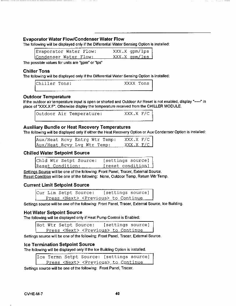
Evaporator Water Flow/Condenser Water FlowThe fo ll owing wil l be displayed only if the Diffe rential Water Sensing Option is installed :
Evaporator Water Flow: XXX.X gpm/lps
Condenser Water Flow: XXX.X m 1 s
The possible values for un its a re "gpm" or "Ips"
Chiller TonsThe following will be d i splayed only if the Differential Water Sensing Option is installed :
Chiller Tons: XXXX Tons
Outdoor TemperatureIf the outdoor air temperature input is open or shorted and Outdoor Air Reset is not enabled, display "---" inplace of "XXX.X F". Otherwise display the temperature received from the CHILLER MODULE.
Outdoor Air Temperature: XXX.X F/C
Auxiliary Bundle or Heat Recovery TemperaturesThe fo l low i ng will be d isplayed only if either the Heat Recovery Option or Aux Condenser Option is installed :
x/Heat Rcvy Entrg Wtr Temp: XXX.X F/C
x/Heat Rcvv Lvcr Wtr Temn: XXX.X F/C
Chilled Water Setpoint Source
Chld Wtr Setpt Source: [settings source]
Reset Condition: [reset condition]
Sett i ngs Source wi ll be one of the follow i ng : Front Panel , Tracer , External Source .
Reset Condition wi ll be one of the following : None , Outdoor Temp , Return Wtr Temp .
Current Limit Setpoint Source
Cur Lim Setpt Source: [settings source]
Press <Next> <Previous> to Continue
Sett i ngs source will be one of the follow i ng : Front Panel , Tracer , External Source , Ice Building .
Hot Water Setpoint SourceThe following will be displayed only if Heat Pump Control is Enabled:
Hot Wtr Setpt Source: [settings source]
Press <Next> <Previous> to Continue
Settings source will be one of the following: Front Panel, Tracer, External Source.
Ice Termination Setpoint SourceThe following will be displayed only i f the Ice Building Option is installed .
Ice Termn Setpt Source: [settings source]
Press <Next> <Previous> to Continue
Settings source will be one of the following : Front Panel , Tracer.
CVHE-M-7 40

Refrigerant ReportThe Refrigerant Report Group sequence is as follows :
Report Heading
Refrigerant Temp & Pressure Report
Press <Next> <Previous> to ContinuE
Evaporator and Condenser Refrigerant Pressure
Evap Rfgt Pressure:r ..-„a D -p,..+- n -,. --, , ,.... .
Saturated Evaporator Temperature/Evaporator Refrigerant PressureTh is screen was added for CTV UCP2 Phase C Release .
Saturated Evap Temp: XXX.X f/c
Evap Rfqt Pressure: XXX.X f/c
Saturated Condenser Temperature/Condenser Refrigerant Pressure
3aturated Cond Temp: XXX.X F/C
:^ond Rfqt Pressure: XXX.X psict
Saturated Evap Temp. and Discharge Temp.
Sat Evap Rfgt Temp:
Press <Next> <Previous>
Pu rge Operating Mode/Purge Status
Purge Operating Mode:
Possible values of [mode] a re : Auto , Stop , On and Adapt i ve .Possible values of [status] are :
Idle
RunningPumpoutService Pumpout
Running - Pumpout Inhibited by low Temp .Pumpout Maximum Rate Disabled
Purge Alarm Message :
Possible values for [status] are :No Diagnostics Exi'st The [Help Message] is : Press <Next> <Previous> to ContinueDiagnostic Alarm The [Help Message] is : Go to Diag , Menu for Description/Reset
Purge Suction Temperature/Purge Liquid Temp .
Purge Alarm Msg: [status]
[Help Messaae]
XXX.X psig
XXX.X bsia
XXX.X F/C
[mode]
(Condensing Un it is Oft)
(Condensing Unit is On)(Temperature initiated pumpout)(Pumpout initiated by the service switch)
(Pumpout inhibited by low liquid temp)
(Max . Pumpout Rate alarm disabled)
Purge Suction Temp: XXX.X F/C
Purge Liquid Temp: XXX.X F/C
41 CVHE-M-7
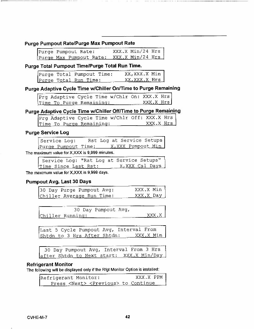
Purge Pumpout Rate/Purge Max Pumpout Rate
Purge Pumpout Rate: XXX.X Min/24 Hrs
Pur e Max Pumpout Rate: XXX.X Min / 24 Hrs
Purge Total Pumpout Time/Purge Total Run Time .
Purge Total Pumpout Time: XX , XXX.X Min
Pur e Total Run Time: XX , XXX.X Hrs
Purge Adaptive Cycle Time w/Chiller On/Time to Purge Remaining
Prg Adaptive Cycle Time w/Chlr On: XXX.X Hrs
Time To Pur e Remainin : XXX.X Hrs
Purge Adaptive Cycle Time w/Chiller Off/Time to Purge Remaining
Prg Adaptive Cycle Time w/Chlr Off: XXX.X Hrs
Time To Pur e Remainin : XXX.X Hrs
Purge Service Log
IService Log: Rst Log at Service Setups
Pur e Pumpout Time: X XXX Pum out Min
The maximum valu e for X,XXX is 9 ,9 99 minutes.
Service Log: "Rst Log at Service Setups"
Time Since Last Rst: X , XXX Cal Da y sThe maximum va lue for X ,XXX is 9 , 999 days.
Pumpout Avg. Last 30 Days
30 Day Purge Pumpout Avg: XXX.X Min
Chiller Averaqe Run T ime: XXX.X Day
30 Day Pumpout Avg,
Chiller Running: XXX.X
Last 5 Cycle Pumpout Avg, Interval From
Shtdn to 3 Hrs After Shtdn: XXX.X Min
30 Day Pumpout Avg, Interval From 3 Hrs
-ter Shtdn to Next start: XXX.X Min/Da,
Refrigerant MonitorThe follow i ng will be displayed only if the Rfgt Monitor Optio n is installed :
Refrigerant Monitor: XXX . X PPM
Press <Next> <Previous> to Continue
CVHE-M-7 42

Compressor ReportThe Compressor Report Group sequence is as follows:
Report Heading
Compressor Hours, Starts & Amps
Differential Oil Pressure , Oil Temperature
Differential Oil Pressure: XXX . X [units]n; i m -„-,t. m .,,.,,-, '.,--,+- ,, ,.-... vvv vL- / r
The possib le value for [units] is " ps id " or "kPa " dependent upon whether English or SI units are selected .
Compressor Speed CommandThe follow i ng w i ll be d isplayed only if the Starter Type is Adjustable Frequency
Compressor Speed Command: XX . X Hzr,,,., ,-. , ., ,. - - „ ,., c-.. ., A vvv v s.
Discharge Oil Pressure , Oil Tank Pressure
Discharge Oil Pressure: XXX.X psign m -, -v n ,.-„ --, , ,., !, . VVV V --, ..
Inlet Guide Vane PositionThis screen was addes for CTV UCP2 Phase B Release .
Inlet Guide Vane Position:r ,-, Il. + r, , ; A,. 7 T -, ,,, ,. T:),, r ; +- ; „ ,-. .
XXX.X Open
.X Dearees
Compressor Phase Currents % RLA
Compressor Phase Currents - % RLA
Compressor Phase Currents Amps
Compressor Phase Currents - Amps
Compressor Phase VoltagesThe following will be displayed only if the Line Voltage Sensing Option is installed .
Compressor Phase Voltages
AB XXXX v BC XXXX v CA XXXX v
Compressor Power Factor and WattsThe following will be displayed only if the Line Voltage Sensing Option is installed .
:ompressor Power Factor: XX %
:ompressar KiloWatts: XXXXX KW
Compressor Winding Temperatures
Compressor Winding Temperatures
W1 XXX F/C W2 XXX F/C W3 XXX F/C
43 CVHE-M-7

Compressor Starts and Runn i ng TimeThe sta rts and hours cou nte rs a re d is played as fo ll ows:
Compressor Starts: XXXXXr ....,... ,. , .. - - .. ,- T ; ,,, .. . VD C . M T TT . C L' f`
Bearing Temperatures #1 and #2The following w il l be dis pl ayed only if the Beari ng Temp Sensors option is installed .
FBearing Temperature 1: XXX.X F/C
Bearin Tem erature 2: XXX.X F C
Solid State Starter Heat Sink TempThe fo ll owinq wil l be disp l ayed only i f the So lid State Starter is instal led
3olid State Starter Heat Sink: XXX.X F/C
Press <Next> <Previous> to Continue
HGBP TimeThe follow i n4 will be d isplayed only If HGBP is installed in the unit .
iGBP Time: HRS:MIN:SEC
Press <Next> <Previous> to Continue
CVHE-M-7 44

Settings Group KeysThe 4 Sett i ngs G roup keys for CVHE/CVHF are :
° Operator Settings° Service Settings° Service Tests° Diagnostics
Operator Settings GroupThe Operator Setting Group sequence is as follows :
Report Heading
Chilled Water & Current Limit Setpts
Press <Next> <Previous> to Continue
Follow i ng proper password entry or suppression the rema i ning sequence will follow :
If the Menu Settings Password is Enabled in the Service Setup Group, following each setting group headingthe follwoing will be displayed:
Settings In This Menu Are [status]
[password messaael
Likewise, if the Menu Settings Password is Disabled in the Service Setup Group, the above screen will besuppressed.
The possible values for status are "Locked" or "Unlocked". If the password status is locked, the passwordmessage will be "Enter Password to Unlock". The user will then depress/_^^^ followed by the<Enter> key. The password keystrokes will be echoed to the screen as a v^ u I`^id he last six keystrokesrepresent the current password and up to twenty keystrokes can be entered. An incorrect password or thetwenty-first keystroke will result in the password message "Invalid Password".
If the password status is unlocked , the password message will be "Press <Enter> to Lock". Press i ng <Enter>locks the sett i ngs in ALL menus . If the password is entered to unlock the sett i ngs , this unlocks the settings inALL menus .
Whenever a password is in use the "Press<+><-> to change setting" message will suppressed on setpointscreens . Any attempt to change the setting will result in the message "Sett i ng is Locked" . The passwordonce ente red wil l remain valid until canceled .
Purge Operating Mode
Purge Operating Mode: [mode]Press <+> <-> to Change Setting
Possible values of (mode) are : Off, On , Adaptive , Factory Default is Auto .
45 CVHE-M-7

Time Of Day Setting
Current Time/Date HH:MM Xm Mon, XX XXXX
<Enter> to Change <Next> to Continue
The top leve l "Current Time/Date" will be d isplayed when this screen is first selected . Press ing the <Next> or<P re vio us> key will go to the next o r prev ious screen as usua l.
If the <Enter> key is selected, five separate screens can be displayed with which the time may be set. The
"Current Time/Date" will be displayed on line one of each of these screens. Each of these screens will
change one element of the current time/date. The second line of each screen will indicate which element of
the current time/data is being changed as well as it's current value. The instructional messages which are
normally displayed on line two will not be present although the instructions which would normally be displayed
are still valid ...i.e. if the setpoint has been changed, <Enter> or <Cancel> must be pressed to continue. If the
first time changing screen is being displayed and the <Previous> key is pressed, the top level "Current
Time/Date" screen will be displayed and the <Enter> key will have to be selected to re-enter the time
changing screens. If the fifth time changing screens is being displayed and the <Next> key is pressed, the
next screen will be displayed. If <Previous> is selected at this point, the top level "Current time/Date" screen
will be displayed and the <Enter> key will have to be selected to re-enter the time changing screens.
In order to change an element of the current time/date, select <Enter> from the top level "Current Time/Date'
screen to enter the time changing screens. Hit <Next> or <Previous> to get to the proper screen. Press the<+> <-> keys to change the element to it's proper value and press the <Enter> key to store the new time/date.
A message "Updating Chiller Clock. Please Wait" is displayed for two seconds after the <Enter> key is
pressed.
The five time changing screens are as follows :
Current Time/Date HH:MM xm Mon
Chanae Hour: <+> <-> and <Enter>
Current Time/Date HH:MM xm Mon
Chanae Minute: <+> <-> and <En
Current Time/Date HH:MM xm Mon
Chanae Month: <+> <-> and <Ent
Current Time/Date HH:MM xm Mon
C'hancre Dav: <+> <-> and <Enter
XX,XXXX
HH
XX,XXXX
r> MM
XX,XXXX
> MON
XX,XXXX
Current Time/Date HH:MM xm Mon XX,XXXX
Change Year: < +> <-> and <Enter> XX
Front Panel Chilled Water Setpoint
Front Panel Chilled Wtr Setpt: XXX.X F/C
Press <+> <-> to Change Sett i ng
Range of Values is 0 to 65 F (- 17 . 8 to 18 . 3C) in increments of 1 or 0 . 1 F or C depending on the Service Setup
Screen XXX or XXX .X . Factory default is 44 . 0 F (6 . 7 C) .
As shown above, the second line of a setting display normally says:
"Press <+> <-> to Change Setting"
CVHE -M - 7 46

The following is displayed as the second line of the display if an attempt is made to increment the setpointabove the end of the setpoint range:
"Top of Range , Press <-> to Change"
The following is displayed as the second line of the display if an attempt is made to decrement the displaybelow the end of the setpoint range :"Bottom of Range, Press <+> to Change"
The following is displayed as the second line of the display if a key other then <+>, <->, <Enter>, or <Cancel>is pressed after <+> or <-> is pressed:"Press <+> <-> <Enter> <Cancel> to Advance"
The exception to the above message i s when the <Stop> key is depressed . Stop is always active . Othermessages are disp layed on the second l i ne of the d isplay for special cases as noted below in association withthe affected setpo i nt d i splay .
When the Front Panel Ch ill ed Water Setpo i nt is w ithin 1 . 7 F of the Leaving Water Temperature CutoutSetpoint or within 6 F of the Low Refrigerant Temperature Cutout Setpoint , the second line of this display wi llread :
"Limited by Cutout Setpt, <+> to Change"
Front Panel Current Limit Setpoint
Front Panel Current Limit Stpt: XXX %
Press <+> <-> to Change Sett ina
Range of Values is 40 to 100% i n increments of 1 % Factory Default is 100%
Front Panel Hot Water SetpointThe Front Panel Hot Water Setpoint is only displayed when the Hot water option is enabled.
Front Panel Hot Wtr Setpt: XXX.X F/C
Press <+> <-> to Change Setting
Range of va l ues is 80 to 125 F (26 . 7 to 51 .7C) in increments of 1 or 0 . 1 F or C depending on the ServiceSetup Screen XXX or XXX .X . Facto ry Default is 90 F (32 .2C) .
Free Cooling EnableThe free cooling enable screen is displayed only if the free cooling option is installed .
Free Cooling [status]
Press <+> <-> to Change Setting
Possible values of [status] are : On , Factory Default is Off.
Chilled Water Reset Type
Chilled Water Reset Type [type]
Press <+> <-> to Change Setting
Possible values for [type] are: Return, Constant Return, Outdoor Air, Factory Default is Disable
If either Disable or Constant Return are selected , the remaining chilled water reset displays are skipped bythe human interface . If either Return or Outdoor Air are selected , the first word of the remaining chilled waterreset displays will be the type of reset .
47 CVHE-M -7
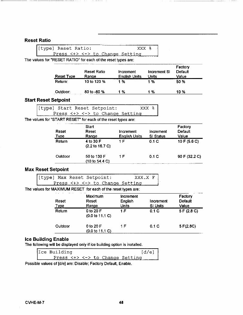
Reset Ratio
[type] Reset Ratio: XXX %
Press <+> <-> to Change Setting
The values for "RESET RATIO" for each of the reset types are :
FactoryReset Ratio Increment Increment SI Default
Reset Type Range Enqlish Units Units ValueReturn : 10 to 120 % 1% 1% 50%
80 to -80 % 1% 1% 10%
Start Reset Setpoint
[type] Start Reset Setpoint: XXX %Press <+> <-> to Change Setting
The values for "START RESET"for each of the reset types are :
Start FactoryReset Reset Increment Increment DefaultType Range English Units SI Status ValueReturn 4 to 30 F 1 F 0 . 1 C 10 F(5 .6 C)
(2 .2 to 16 . 7 C)
Outdoor 50 to 130 F 1 F 0 . 1 C 90 F (32 . 2 C)(10 to 54 .4 C)
Max Reset Setpoint
[type] Max Reset Setpoint: XXX.X F
Press <+> <-> to Change Setting
The values for MAXIMUM RESET for each of the reset types are :
Maximum Increment FactoryReset Reset English Increment DefaultType Range Units SI Units ValueReturn 0 to 20 F 1 F 0 . 1 C 5 F(2 . 8 C)
(0 . 0 to 11 . 1 C)
Outdoor 0 to 20 F 1 F(0 . 0 to 11 . 1 C)
Ice Building EnableThe following will be displayed only if ice building option is installed .
0.1 C 5 F (2 .8C)
Ice Building [d/e]
Press <+> <-> to Change Settina
Poss i ble values of [d/eJ are : Disable ; Factory Default , Enable .
CVHE-M-7 48

Front Panel Ice Termination SetpointThe following will be displayed only if ice building option is installed.
Panel Ice Termination Setpoint : XXX. X F/CPress <+> <-> to Chanae Settina
Range of values is 20 to 32 . 0 F(6 . 7 to 0 . 0 C) in increments of 1 or 0 . 1 F or C depending on the ServiceSetup Screen XXX or XXX .X . Factory Default is 27 . 0 F (-2 . 8 C) .
Ice Making to Normal Cooling Transition TimerThis screen was added for CTV UCP2 Phase B Release .The following will be displayed only if ice building option is installed .
Ice To Normal Transition: XX MIN
Press <+> <-> to Change Setting
Range of va l ues is o to 10 minutes . Defa u lt is 5 m in utes .
Chilled Water Setpoint SourceIf the Tracer option is installed the word "DefaulY" will appear in front of the setpoint source.
[Default] Chilled Water Setpoint Source:
[source]
Possible values of [source] are Front Panel is Factory Default.Future 1Future 2External SourceFuture 3
Current Limit Setpoint SourceIf the Tracer option is installed the word "Default" will appear in front of the setpoint source.
[Default] Current Limit Setpoint Sourcefsourcel
Possible values of [source] are Front Panel ; Factory Default .FuturelFuture 2External Source
Hot Water Setpoint SourceIf the Tracer option is insta l led the word "Defau lt" will appear i n front of the setpo i nt source . The following willbe d isplayed only if Heat Pump Controls enabled .
Hot Water Setpoint Source
fsourcel
Possible values of [source] are Front Panel; Factory DefaultFuture 1Future 2External SourceFuture 3
49 CVHE-M-7

Ice Termination Setpoint SourceIf the Tracer option is installed the word "Defau lt" will appear in front of the setpoint source . The following will
be displayed only if the Ice Building Opti on is installed .
[Default] Ice Termination Setpoint Source
fsourcel
Possible values of [source] are : Front Panel ; Factory DefaultFuture IFuture 2
Setpoint Source OverrideThis screen was added for CTV UCP2 Phase B Release .
Setpoint Source Override:[source]
Possible values of [source] are: None - ROM DefaultUse Front Panel SetpointsOverride Tracer. Use Default Setpoints. (Available only if Tracer
Option is installed).
CVHE-M-7 50

Service Settings GroupThe Service settings menu has three distinct grouping of items within it. The first group is the basicset setupsnon-password protected group that consists of all of the settings, feature enables, setpoints etc, that arebenign; while they are unlikely to be changed often by a user or operator. Changes in them do not seriouslyeffect the standard protection or reliability of the chiller.
The other two groupings are protected , each with a separate password . These two groups are for changingparameters and setti ngs regarding field commissioning and fundamental protection and control of the chillersubsystems (Field Startup) or for programming of the UCM as to how the specific chiller was built in thefactory (Machine Config uration) . Once properly set , the items in these protected menus should never bechanged again without specific knowledge of the effects of the changes .
CAUTION : Sett ings i n the Service Settings Group are only be set or changed by quaffied Traneservice technic ians . Improper sett i ngs in th is group may adversely affect the operation of the unit .
Menu Structure Under The Service Settings Key
Service Settings Key
Service Settinps Group
I QA17VQQ Pasavw rd Screen
I IQ17QVQ17
Pasanwrd Screen
Field Sta rt up Group
Machine Configuration Group
51 CVHE-M-7

Service Settings - Basic Setups
Service Settings: Basic Setups
Rss <Next> <Previous> to Contir
Menu Settings PasswordIf the Menu Settings Password is Enabled in the Service Setup Group , following each setting group heading
the following will be displayed :
Settings In This Menu Are [status]
If the Menu Settings Password is disabled in the Service Setup Group , the above screen will be suppressed .
The possible values for [status] are "Locked" or "Unlocked". If the password status is locked, the password
message will be "Enter Password to Unlock". The user will then depress ^^^^^ followed by the
<Enter> key. The password keystrokes will be echoed to the screen as a e last six keystrokes
represent the current password and up to twenty keystrokes can be entered. An incorrect password or the
twenty-first keystroke will result in the password message "Invalid Password".
If the password status is unlocked , the password message will be "Press Enter to Lock". Press i ng <Enter>
will lock all of the setpoint menus . Likew ise , if the password status is locked and the correct password isentered , all of the setpoint menus will be un lo cked .
Whenever a password is in use the " Press <+> <-> to change setting " message will be suppressed on all
setpoint screens . Any attempt to change a setpoint will result i n the message "Setting is Locked" being
displayed for 1 second . The password once entered will rema in valid until canceled .
Keypad/Display LockoutThis display only appears if the keypad lockout feature is enabled.
Press <Enter> to Lock Display & Keypad
Password Will be Reauired to Unlock
If the <Enter> key is pressed to lock the keypad , the fo l lowing message is displayed , and all further input from
the keypad is ignored , including the <Stop> key , unt i l the password is enter. The password cons ists of
pressing the <Previous> and <Enter> keys at the same time
******DISPLAY AND KEYPAD ARE LOCKED**********^^** *******
If the keypad is locked and the password is entered, the display will go to the Chiller Operating Report.
Language SettingTh is screen will not be installed until the l anguages a re instal led 2/28/94 .
Language: XXXXXXXX
Press <+> <-> to Chanae Settina
Possible language se lections are : English ; Factory Default , Francais , Deutch , Espanol , Nippon (also known
as Katakan , Use Japanese characters) , Italiano and Nederlands .
CVHE-M-7 52

Display Units
Display Units: [type]
"Press <+> <-> to Change Setting "
Poss i ble values of [type] are : SI , Factory Defau l t is Eng lish .
Decimal Places Displayed Setpoint :
Decimal Places Displayed: [status]"Press <+> <-> to Change Setting "
Poss i b le choices for [status] are : XXX , Facto ry Default is XXX .X .
Display Menu Headings Enable
Display Menu Headings: [d/e]
Press <+> <-> to Change Setting
The fa ctory default value is Enab led . If th e setting is changed to d isabled the Menu Headings in each Menuor G roup will be suppressed .
Differential to Start Setpoint
Differential to Start Setpoint: XXX.X F/C
Press <+> <-> to Change Setting
Range of values is 1 to 10 F (0 . 5 to 5 . 5 C) i n in crements of 1 or 0 . 1 F or C depending on the Service SetupScreen XXX or XXX .X . Factory defau lt is 5 F (2 . 8 C).
Differential to Stop Setpoint
E
Differential to Stop Setpoint: XXX.X F/C
Press <+> <-> to Change Setting
Range of va l ues is 1 to 10 F (0 . 5 to 5 . 5 C) in in crements of 1 or 0 .1 F or C depending on the Se rvice SetupScreen XXX or XXX .X Factory default is 5 F (2 . 8 C).
Evap Pump Off Delay Time
Evap Pump Off Delay: XXX MinPress <+> < - > to Change Settin g
Range of values is 1 to 30 minutes in increments of 1 minute . Factory default is 1 m inute .
Clear Restart Inhibit Timer
Press <Enter> to
Clear the Restart Inhibit Timer
When <Ente r> is pushed a 2 second message appea rs as shown below and then retu rns to above screen .
Restart Inhibit Timer Has Been Cleared
53 CVHE-M-7

Field Startup Group Password Request
Pswd Reqd to Access Field Startup Group
The Field Start-up Group Password is QQ00^^ <Enter>. Successfully entering the password
sends you to the Field Start-up Group Heading Screen as defined below.
Machine Configurating Group Password Request
IPswd Reqd to Access Machine Config Group
Please Enter Password
The Mach i ne Config u ration G roup Password is &17,A000 <Enter> . Successfully entering the passwo rd
sends you to th e Mach ine Configu rat i on Group Head ing Screen .
CVHE-M-7 54
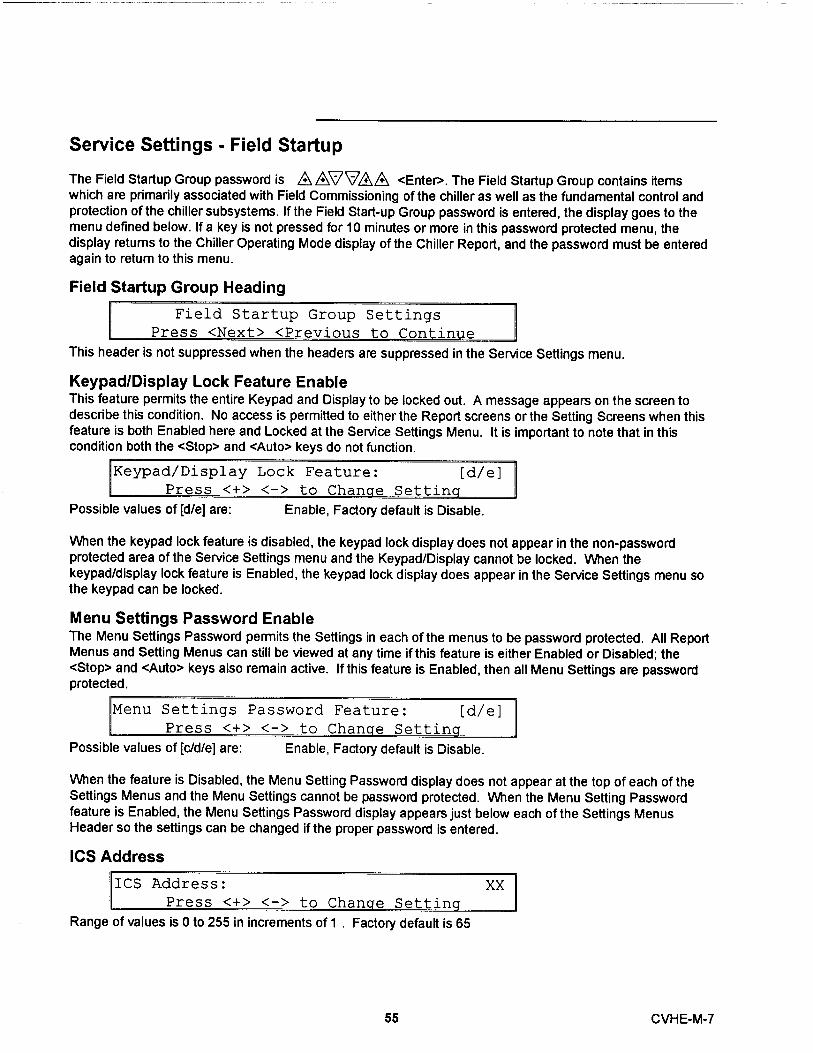
Service Settings - Field Startup
The Field Startup Group password is 0A0V00 <Enter>. The Field Startup Group contains itemswhich are primarily associated with Field Commissioning of the chiller as well as the fundamental control andprotection of the chiller subsystems. If the Field Start-up Group password is entered, the display goes to themenu defined below. If a key is not pressed for 10 minutes or more in this password protected menu, thedisplay returns to the Chiller Operating Mode display of the Chiller Report, and the password must be enteredagain to return to this menu.
Field Startup Group Heading
Field Startup Group Settings
^ss <Next> <Previnus to ('nnt -
This header is not suppressed when the headers are suppressed in the Service Settings menu .
Keypad/Display Lock Feature EnableThis feature permits the entire Keypad and Display to be locked out. A message appears on the screen todescribe this condition. No access is permitted to either the Report screens or the Setting Screens when thisfeature is both Enabled here and Locked at the Service Settings Menu. It is important to note that in thiscondition both the <Stop> and <Auto> keys do not function.
Keypad/Display Lock Feature: [d/e]Press <+> <-> to Change Setting
Possible va l ues of [d /e] are : E n a ble , Factory defau lt is Disable .
When the keypad lock feature is disabled, the keypad lock display does not appear in the non-passwordprotected area of the Service Settings menu and the Keypad/Display cannot be locked. When thekeypad/display lock feature is Enabled, the keypad lock display does appear in the Service Settings menu sothe keypad can be locked.
Menu Settings Password EnableThe Menu Settings Password permits the Settings in each of the menus to be password protected. All ReportMenus and Setting Menus can still be viewed at any time if this feature is either Enabled or Disabled; the<Stop> and <Auto> keys also remain active. If this feature is Enabled, then all Menu Settings are passwordprotected.
Menu Settings Password Feature: [d/e]Press <+> <-> to Change Setting
Possi ble va l ues of [c/d/e] a re : Enab le, Fa cto ry defa u lt is D isab le.
When the feature is Disabled, the Menu Setting Password display does not appear at the top of each of theSettings Menus and the Menu Settings cannot be password protected. When the Menu Setting Passwordfeature is Enabled, the Menu Settings Password display appears just below each of the Settings MenusHeader so the settings can be changed if the proper password is entered.
ICS Address
ICS Address:
<+> < - > t
Range of values is 0 to 255 in increments of 1 . Factory defau lt is 65
XX
55 CVHE-M-7
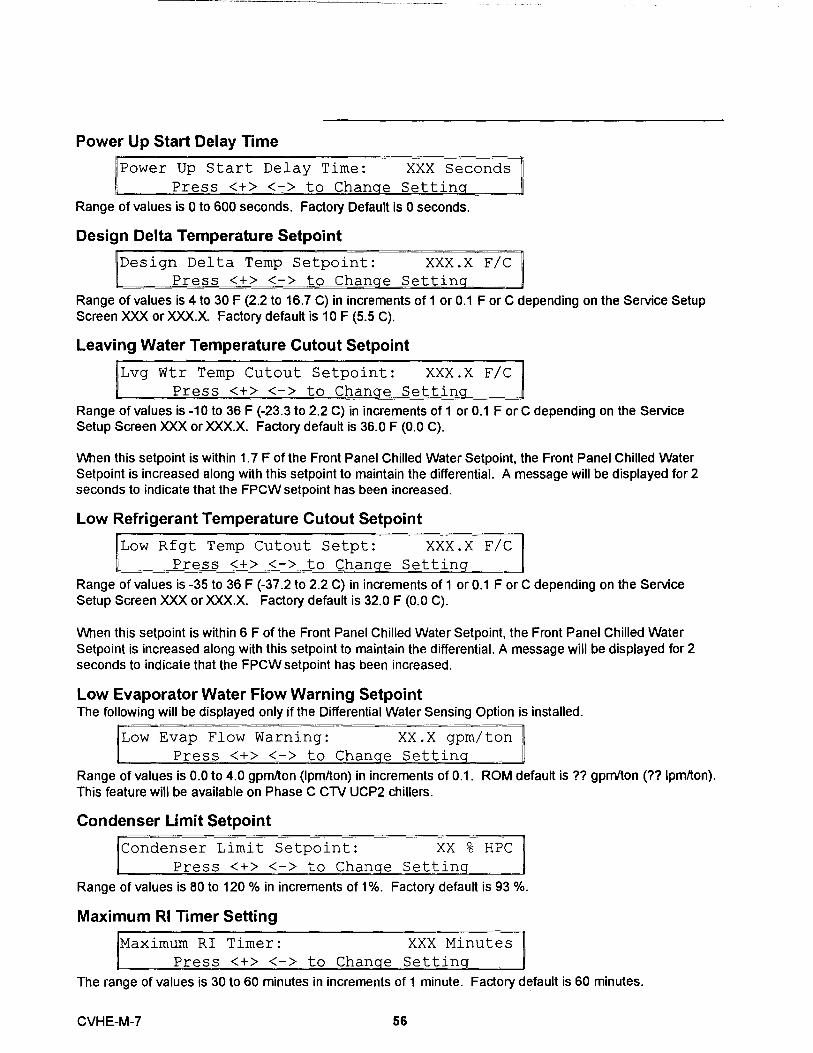
Power Up Start Delay Time
Power Up Start Delay Time: XXX Seconds
Press <+> <-> to Change Setting
Range of values is 0 to 600 seconds . Factory Default is 0 seconds .
Design Delta Temperature Setpoint
IDesign Delta Temp Setpoint: XXX.X F/C II
Press <+> <-> to Chanae Setting
Range of values is 4 to 30 F (2.2 to 16.7 C) in increments of 1 or 0.1 F or C depending on the Service SetupScreen XXX or XXX.X. Factory default is 10 F (5.5 C).
Leaving Water Temperature Cutout Setpoint
Lvg Wtr Temp Cutout Setpoint: XXX.X F/C
Press <+> <-> to Change Setting
Range of values is - 10 to 36 F (-23 . 3 to 2.2 C) in increments of 1 or 0 . 1 F or C depending on the ServiceSetup Screen XXX or XXX.X . Factory default is 36 . 0 F (0 . 0 C) .
When this setpo i nt is within 1 . 7 F of the Front Panel Chilled Wate r Setpoint , the Front Panel Chilled Water
Setpo i nt is increased along with this setpoint to mainta i n the d ifferential . A message will be d isplayed for 2seconds to i ndicate that the FPCW setpo i nt has been increased .
Low Refrigerant Temperature Cutout Setpoint
Low Rfgt Temp Cutout Setpt: XXX.X F/C
Press <+> <-> to Change Sett ing
Range of values is -35 to 36 F (-37 . 2 to 2 . 2 C) in i ncrements of 1 or 0 . 1 F or C depending on the ServiceSetup Screen XXX or XXX .X . Factory default is 32 . 0 F (0 . 0 C) .
When th is setpo i nt is within 6 F of the Front Panel Chilled Water Setpo i nt , the Front Panel Chilled WaterSetpoint is increased along with this setpoint to mainta i n the d i fferent i al . A message will be d isplayed for 2seconds to i ndicate that the FPCW setpo i nt has been i ncreased .
Low Evaporator Water Flow Warning SetpointThe following will be displayed only if the Differential Water Sensing Option is installed.
Low Evap Flow Warning: XX.X gpm/ton
Press <+> <-> to Change Settina
Range of values is 0 . 0 to 4 . 0 gpm/ton ( Ipm/ton) in increments of 0 . 1 . ROM default is ?? gpm/ton (?? Ipm/ton) .This feature will be available on Phase C CTV UCP2 ch i llers .
Condenser Limit Setpoint
Condenser Limit Setpoint: XX % HPC
Press <+> <-> to Change Settinq
Range of values is 80 to 120 % in increments of 1% . Factory default is 93 % .
Maximum RI Timer Setting
Maximum RI Timer: XXX Minutes
Press <+> <-> to Change Settinq
The range of values is 30 to 60 minutes in increments of 1 minute . Factory default is 60 minutes .
CVHE-M-7 56

Purge Service Log Reset
Service Log: "Press <Enter> to Reset"
Purge Pumpout Time: X,XXX Pumpout Min
The maximum va l ue for X,XXX is 9 , 999 minutes
Service Log: "Press <Enter> to Reset"
Time Since Last Rst: X,XXX Cal Days
The maximum value for X ,XXX is 9 , 999 days .
Note: Resetting in either screen above will reset both pieces of data to Zero.
Purge Maximum Pumpout Rate
?urge Max Pumpout Rate: XX Min/24 Hrs
Press <+> <-> to Change Setting
Range of values is 1 to 100 minutes/24 hours in i ncrements of 1 minute/24 hou rs . Factory default is 20minutes/24 hours .
Purge Disable Pumpout Alarm
?rg Disable Pumpout Alarm for: XX Hrs
Press <+> <-> to Change Setting
Range of values is 1 to 72 hours in increments of 1 hour . Factory default is 0 hours .
Purge Low Chiller Sat. Cond . Liquid Temp Protection Enable
Prg Low Liquid Temp Inhibit Enable: [d/e]
Press <+> <-> to Change Setting
Possible values of [d/e] are: Disable; Factory Default is Enable
Purge Low Chiller Sat. Cond. Temp Setpoint
Prg Low Liq Temp Inhibit Setpt XX.X F/C
Press <+> <-> to Change Setting
Range of values is 32 to 50 F (0.0 to 10.0 C) in increments of 1 or 0.1 F or C depending on the Service SetupScreen XXX or XXX.X. Factory default is 40 F (4.4 C). Does not display this menu item unless this feature isenabled in the menu above.
Surge Protection Enable
3urge Protection: [d/e]
Press <+> <-> to Change Setting
Possible values of [d /e] are : Disab l e , Factory default is Enable .
Under/Over Voltage Protection EnableThis screen is displayed only when line voltage sensing is installed .
Under/Over Voltage Protection: [d/e]
Press <+> <-> to Chanae Settina
Possible values of [d /e] a re : D i sable , Factory Default i s Enable
57 CVHE-M-7
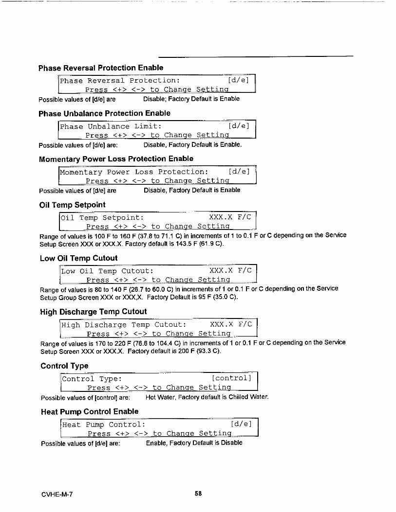
Phase Reversal Protection Enable
Phase Reversal Protection: [d/e]
Press <+> <-> to Chanae Settina
Poss i ble values of [d /e] are D isable ; Factory Default is Enable
Phase Unbalance Protection Enable
Phase Unbalance Limit: [d/e]
Press <+> <-> to Change Setting
Possible values of [d/e] are : D isable , Factory Default is Enable .
Momentary Power Loss Protection Enable
Momentary Power Loss Protection: [d/e]
Press <+> <-> to Change Setting
Possibl e values of [d/e] are Disab le, Facto ry Defa ult is Enab le
Oil Temp Setpoint
Oil Temp Setpoint: XXX.X F/C
Press <+> <-> to Change Setting
Range of va l ues is 100 F to 160 F (37 . 8 to 71 . 1 C) in increments of 1 to 0 . 1 F or C depending on the Service
Setup Screen XXX or XXX .X . Factory default i s 143 . 5 F (61 . 9 C) .
Low Oil Temp Cutout
ILow Oil Temp Cutout: XXX . X F/C
Press <+> <-> to Change Settinq
Range of values is 80 to 140 F (26 . 7 to 60 .0 C) i n increments of 1 or 0 . 1 F o r C depending on the Service
Setup G roup Screen XXX or XXX ,X . Fa ctory Default i s 95 F (35 .0 C) .
High Discharge Temp Cutout
High Discharge Temp Cutout: XXX.X F/C
IPress <+> <-> to Change Settincl
Range of values is 170 to 220 F (76 .6 to 104 . 4 C) in in crements of 1 or 0 . 1 F or C depending on the Service
Setup Screen XXX or XXX .X . Fa ctory default is 200 F (93 . 3 C) .
Control Type
Control Type: [control]
Press <+> <-> to Chancte Settina
Poss i ble values of [contro l ] are : Hot Wate r, Factory default is Chill ed Water.
Heat Pump Control Enable
Heat Pump Control: [d/e]
Press <+> <-> to Change Settina
Possible values of [d/e] a re : Enable , Factory Defau lt is Disable
CVHE-M-7 58

Control Sensitivity
Control Sensitivity : [type]Press <+> <-> to Change Setting
Possible va l ues of [type] are : Process , Factory Default is Comfort
External Vane Control Enable
External Vane Control Enable: [d/e]Press <+> <-> to Change Setting
Poss i ble values of [d /e] are : Enable , Factory Default is D isable
Soft Load Control Enable
Soft Load Control: [d/e]Press <+> <-> to Change Setting
Possible values of [d /e] are : Enable , Factory Default is Disable .
Soft Load Starting Current Limit
Soft Load Starting Current Limit: XX %Press <+> <-> to Chang e Settin
Range of va l ues is 40 to 100 % in in crements of 1 %. Fa ctory Defau lt i s 100%.
Soft Load Current Limit Rate of Change
Soft Load Current Limit Rate: XX %/minPress <+> <-> to Change Setting
Range of values is 0 . 5 to 5 %/m i n in i ncrement s of 1 or 0 . 1 %/m i n depend i ng on the Service Setup ScreenXXX or XXX.,X . Fa cto ry default is 5 %/mi n .
Soft Load Lvng Wtr Temp Rate of Change
Soft Load Lvg Water Rate: XX F/C/minPress <+> <-> to Change Setting
Range of values i s 0 . 5 to 5 F/m i n (0 . 3 to 2 . 8 C/min) in increments of 1 or 0 . 1 F/min depending on the ServiceSetup Screen XXX or XXX .X . Factory default is 5 F/min (2 . 8 C/min) .
Hot Gas Bypass EnableTh is screen will be suppressed when the hot gas bypass option is not installed .
Hot Gas Bypass Control: [d/e]Press <+> < - > to Chang e Setting
Possible values of [d/e] are : Enable , Factory Default is Disable
Hot Gas Bypass Cut in Vane Pos i tionTh is screen will be supp ressed when the hot gas bypass o ptio n is not i nstalled
Hot Gas Bypass Cut in IGV Position: XX %Pressss <+> <-> to Chang e Setting
Range of va l ues is 0 to 30 % in i n crements of 1%. Factory default is 10 %.
59 CVHE-M-7

HGBP Proportional Gain (Kp) SetptThis screen wil l be suppressed when the hot gas bypass option is not insta l led .
HGBP Proportional Gain Setpt: XXX . X ,IFFactory Default is 10 . 0%/F & 18 . 0 %/C I
The range of va l ues is 0 to 100 %/F (0 to 180 %/C) in increments of 0 . 1 . The factory default is 10 . 0 %/F (18 . 0%/C).
HGBP Integral Gain (Ki) SetptThis screen will be suppressed when the hot gas bypass option is not installed.
HGBP Integral Gain Setpt: X.XXX %/F_Factor Default is 0.110 o F& 0.198 % / C
The range of values is 0 to 1 %/F (0 to 1.8 %/C in increments of 0.001. The factory default is 0.110 %/F(0.198 %/C).
HGBP Derivative Gain (Kd) SetptThis screen will be suppressed when the hot gas bypass option is not installed .
HGBP Derivative Gain Setpt: XX . X %/FFactory Default is 00 . 0 %/F & 00 . 0 %/C
The range of va l ues is 0 to 10 . 0 %/F (0 to 18 . 0 %/C) in increments of 0 . 1 . The factory default is 00 . 0 %/F(00 . 0 %/C) .
LWT Control Proportional Gain (Kp) Setpt
LWT Proportional Gain Setpt: XXX.X o/FFactory Default is 10.0 o/F & 18 . 0 o/C
The range of values is 0 100 %/F (0 to 180 %/C) in increments of 0 . 1 . The factory default is 10 . 0 %/F (18%/C) .
LWT Control Integral Gain (Ki) Setpt
LWT Integral Gain Setpt: X.XXX %/Ftor y default is 0.110 o F& 0.198 o C
The range of values is 0 to 1 %/F (0 to 1 . 8 %/C) in i ncrements of 0 . 001 . The factory default is 0 . 110 %/F(0 . 198 %/C) .
LWT Control Derivative Gain (Kd) Setpt
LWT Derivative Gain Setpt: XX.X %/F
Factory Default is 00.0 o/F & 00 . 0 o/C
The range of va l ues is 0 to 10 . 0 %/F (0 to 18 . 0 %/C) i n increments of 0 . 1 . The factory default is 00 . 0 %/F(00 . 0 %/C) .
IGV MAXIMUM Travel Setpt
IGV MAXIMUM Travel Setpt: XX , XXX StepsPress <+> <-> to Change Setting
Range of values is 0 to 60 , 000 Steps in i ncrements of 100 Steps . Factory default is 50 , 000 Steps .Note : This is also known as the 90 degree vane setting .
CVHE-M-7 60

Guide Vane Open Travel Stop
Guide Vane Open Travel Stop: XX %Press <+> <-> to Change Setting
Range of va l ues is 50 to 100 % in increments of 1 % . Factory default is 100%.
Guide Vanes Closed Travel Stop
Guide Vane Closed Travel Stop: XX %Press <+> <-> to Change Setting
Range of va l ues is 0 to 30 % in in crements of 1% . Factory defau lt is 0 % .
Local Atmospheric Pressure
Local Atmospheric Pressure: XX.X F/C
Press <+> <-> to Change Setting
The range of settings shall be 10 to 16 PS I G in increments of I or 0 . 1 PSIG or kPa depending on the Servi ceSetu p Screen XXX or XXX .X . The factory default is 14 .7 PS I G .
61 CVHE-M-7

Service Settings - Machine Configuration
The Machine Configuration password is QQAQQQ <Enter>. If the machine configuration password isentered, the display goes to the menu defined below. If a key is not pressed for 10 minutes or more in this
password protected menu, the display returns to the Chiller Operating Mode display of the Chiller Report, andthe password must be entered again to return to this menu.
Machine Configuration Group Heading
Machine Configuration Group Settings
Press <Next> <Previous> to Continue
Th is header is not suppressed when the heade rs are suppressed in the Service Sett ings menu .
Unit Fre uencyUnit Frequency:
Press <+> <-> toPoss i ble values of freq are : 50 Hz , Fa ctory
Unit
ROM
Unit Type:
<+> <-> to Change Settiictorv set for CVHE o r CVHF as appri
Unit Tons
Nominal Unit Tons: [tons]
Press <+> <-> to Chang e Settin gPoss i ble values of [tons] are "100" through "1600" i n 10 ton i ncrements . Factory Default is 500 tons .
Refrigerant Type
Refrigerant Type: [type]
Press <+> <-> to Change Setting
Possible values type a re : R11 , R12 , R134a , Water, R22 , Factory Default is R123
Refrigerant Monitor Type
Refrigerant Monitor Type:Press <+> <-> to Change Set
Possible values for type are : 01 - Analog i nterfa ce02 - I PC Interfa ceFactory d efault i s No ne
Starter Type
3tarter Type: [type]
Press <+> <-> to Change Settina
[freq]
[type]
[type]
Possible values for type are: UndefinedVariable SpeedY-Delta: Factory Default.X-LineSolid StateAuto XformerPrimary Reactor
CVHE-M-7 62

Startup Contactor Test - Y-D Starters OnlyThis screen wil l be displayed only when the starte r type is Y-Delta .
2nd Level Contactor Integrity Test:[d/e]
Possible values of [d/e] are: Enable, Factory Default is Disable
Rated Load Amps
Rated Load Amps: XXXX AmpsPress <+> <-> to Change Setting
The range of values is 0 - 2500 in 1 amp increments . ROM default is 500 Amps . Factory set per nameplate .
Motor Heating Constant
Motor Heating Constant Setpt: XXX MinPress <+> <-> to Change Settin g
The ra nge of val ues fo r XXX is 0 to 100 m i n utes in 1 m in u te i n crements . Factory default is 25 m inutes .Set the Moto r Heat i n g Consta nt per th e fol lwoin g table.
NTON Motor Heating60 Hz 50 Hz Constant
230-320 190-270 30 Min .360-500 300-420 35 Min .560-800 470-660 40 Min .890-1280 740-1040 45 Min .
Current Overload Setting #1
Current Overload Setting #1: XXXXXXXX
Press <+> <-> to Change Setting
The range of values is decimal 00 through 31. ROM Dfault is 00. Factory set per nameplate.
Current Overload Setting #2
Current Overload Setting #2: XXXXXXXX
Press <+> <-> to Change Settina
The range of values is decimal 224 through 255. For security purposes the second setting is the 8-bit one'scomplement of the first setting above.
Verify Current Overload Settings #1 and #2 per the following procedure .
63 CVHE-M-7

Procedure for Selecting Current OverloadSettings for UCP2
1 . Determine the Rated Load Amps (RLA) from the UnitNameplate
2. Refer to Table 1 or Table 2 be low as follows:
Select Table 1 i f either of the following conditions are met :a . The unit has a unit mounted starter with an RLA less than
936 Amps .b . The unit has a 24" wide control panel , no unit mounted
starter and RLA less the 936 Amps .
Select Table 2 if either of the following conditions are met :a . The unit has an RLA over 935 Amps .b . The unit has a 38" wide "Starter By Others " control panel .
3. Using Table 1 or Table 2 (determined from Step 2),determine the CT Meter Scale Rating based on the RLA fromStep 1.
4 . Calculate the CT factor using one of the following twoequations :If Table 1 was used : CT Factor = (Motor RLA/CT Meter Scale
Rating) x 100If Table 2 was used : CT Factor = (Motor RLA/CT Meter Scale
Rating) x 139
5. Refer to Table 3 . Determine Current Overload Settings # 1and #2 based on the CT Factor calculated in Step 5.
Verify Current Overload Setting #1 .Verify Current Overload Setting #2 .
6 . If the unit has a Trane supplied starter , verify that the CTPart Number listed in Table 1 or Table 2 matches the numberof the CT used in the starter panel .
7. If the unit has a 38" wide "Starter By Others" control panel,verify that the CT Part Number listed in Table 2 matches thenumber of the CT used in the motor junction box.
CVHE-M-7 64

Table 1CT Factor = (Motor RLA/CT Meter Scale Rating) x 100
Motor CT Part xtensio CT MeterRLA Number Number Scale Rating
34-50 A X13580253 -09 50A51-67 A X13580253 -10 75 A68-100 A X13580253 -01 100A101-134 A X13580253 -02 150 A135-184 A X13580253 -03 200 A185-267 A X13580253 -04 275 A268-334 A X13580253 -05 400 A335-467 A X13580253 -06 500 A468-667 A X13580253 -07 700 A668-935 A X13580253 -08 1000 A
Table 2CT Factor = (Motor RLA/CT Meter Scale Rating) x 139
Motor CT Part Extensio CT MeterRLA Number n Scale Rating
Number24-29 A X13580048 -01 50 A30-36 A X13580048 -01 60 A37-43 A X13580048 -01 75 A44-48 A X13580048 -01 90 A49-60 A X13580048 -01 100 A67-72 A X13580048 -01 125 A73-86 A X13580048 -01 150 A87-96 A X13580048 -01 180 A97-120 A X13580048 -01 200 A121-144 A X13580048 -02 250 A145-168 A X13580048 -02 300 A169-192 A X13580048 -02 350 A193-240 A X13580048 -03 400 A241-288 A X13580048 -03 500 A289-336 A X13580048 -03 600 A337-384 A X13580048 -04 700 A385-480 A X13580048 -04 800 A481-576 A X13580048 -04 1000 A577-720 A X13580048 -05 1200 A721-864 A X13580048 -05 1500 A865-1008 A X13580047 -01 1800 A1009-1200 A X13580047 -01 2100 A1201-1800 A X13580047 -01 2500 A
Table 3
Current CurrentCT Overload Overload
Factor Setting #1 Settin #266 00 25567 01 25468 02 25369 03 25270 04 251
71 06 24972 07 24873 08 24774 09 24675 10 24576 11 24477 12 24378 13 24279 15 24080 15 24081 16 23982 17 23883 18 23784 19 23685 20 23586 21 234
87 22 23388 22 23389 23 23290 24 23191 25 23092 25 23093 26 22994 27 228
95 28 22796 28 22797 29 22698 22599 30 225100 31 224
65 CVHE-M-7

Maximum Acceleration Timer #1
Maximum Accel Timer Setpt #1:
Press <+> <-> to Chanae
The range of values is 2 to 64 seconds .
UndefinedVariable Speed
Y-DeltaX-Line
Solid StateAuto-Transformer
Maximum Acceleration Timer #2
XX Sec
Recommended Maximum
Contact Factory20
27 (Factory Default)62016
Kaximum Accel Timer Setpt #2: XX Sec
Press <+> <-> to Change Setting
The range of values is 191 to 249 seconds. Factory default is 228 seconds. For security purposes thesecond setting is the 8-bit one's complement of the first setting above, or equals 255 minus Timer #1 Setting.Example: Setting #2 is 255 - 27 = 228
External Chilled Water Setpoint Option
4,xternal Chilled Wtr Setpoint: [status]
Press <+> <-> to Change Setting
Possible values for status are :
External Current Limit Set oint Option
External Current Limit Setpt:EPress <+> < - > to Chan e
Poss i ble values for status are : Installed , Factory
Installed, Factory default is Not Installed.
[status]
External Hot Water Setpoint OptionThis display will only be used when hot water control is enabled .
External Hot Wtr Setpoint: [status]
Press <+> <-> to Change Setting
Possible values for status are : I nstalled , Factory default is Not Installed
CVHE-M-7 66
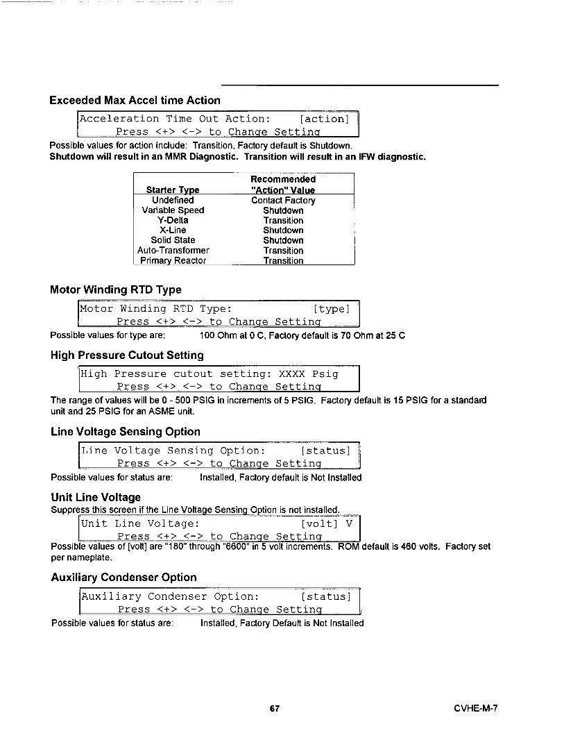
Exceeded Max Accel time Action
^cceleration Time Out Action: [action]
Press <+> <-> to Change Setting
Possible values for action include: Transition, Factory default is Sh utd own.Shutdown will result in an MMR Diagnostic . Transition will result in an IFW diagnostic .
UndefinedVariable Speed
Y-DeftaX-Line
Solid StateAuto-Transformer
Motor Windinq RTD Tvpe
Recommended"Action" ValueContact Factory
ShutdownTransitionShutdownShutdownTransition
[otor Winding RTD Type: [type]
Press <+> <-> to Change Setting
Possible values for type are: 100 Ohm at 0 C, Factory default is 70 Ohm at 25 C
High Pressure Cutout Setting
iigh Pressure cutout setting: XXXX Psig
Press <+> <-> to Change Settina
The range of values will be 0 - 500 PSIG in increments of 5 PSIG. Factory default is 15 PSIG for a standardunit and 25 PSIG for an ASME unit.
Line VOI tBq@ Sensina OptlOtl
,ine Voltage Sensing Option: [status]
Press <+> <-> to Change Setting
Possible values for status are : Installed , Factory default is Not Installed
Unit Line VoltageSuppress th i s screen if the L i ne Volta e Si
Unit Line Voltage:
Press <+> <-> toPossible values of [volt] are " 180 " throughper nameplate .
Auxiliarv Condenser ODtion
Option is not installed.
[volt] V
nqe Settinqin 5 volt increments. RO
iuxiliary Condenser Option: [status]
Press <+> <-> to Change Setting
default is 460 volts . Factory set
Possible values for status are : Installed , Factory Default is Not Installed
67 CVHE-M-7

Heat Recoverv Option
3eat Recovery Option: [status]
Press <+> <-> to Change Setting
Possible values for status are : Installed , Factory default is Not Installed .
Hot Gas Bvpass Option
iot Gas Bypass Option: [status]
Press <+> <-> to Change Settina
Possible values for status are : I nstalled , Factory default is Not Installed .
Free Coolina Option
?ree Cooling Option: [status]
Press <+> <-> to Change Settinq
Possible values for status are : Installed , Factory default is Not Installed .
Condenser Pressure Sensor Option
:ondenser Press. Sensor Option: [status]
Press <+> <-> to Change Setting
Possible values for status are : Installed , Factory default is Not Installed .
Bearinq Temperature Sensors Option
3earing Temp Sensors Option: [status]
Press <+> <-> to Change Setting
Poss i ble values for status are : Installed , Factory default is Not Installed .
Discharge Temperature Sensor Option
Discharge Temp Sensor Option: [status]
Press <+> <-> to Change Setting
Possible values for status are : Installed , Factory default is Not Installed .
Ice Buildin4 Option
[ce Building Option: [status]
Press <+> <-> to Change Setting
Possible values for status are : Installed , Not Installed ; Factory default
Differential Water Press Sensinq Option
)iff Wtr Press Sensor Opt: [status]
Press <+> <-> to change Settina
Possible values for status are: Installed, </= 150 PSIGInstalled, > 150 PSIGNot Installed; Factory default
This option screen applies to both the Evap and Cond differential water pressure sensors for both systemsless than or equal to 150 PSIG (Sensors at the Chiller Module) and systems greater than 150 PSIG (Sensorsat the Options Module).
CVHE-M-7 68
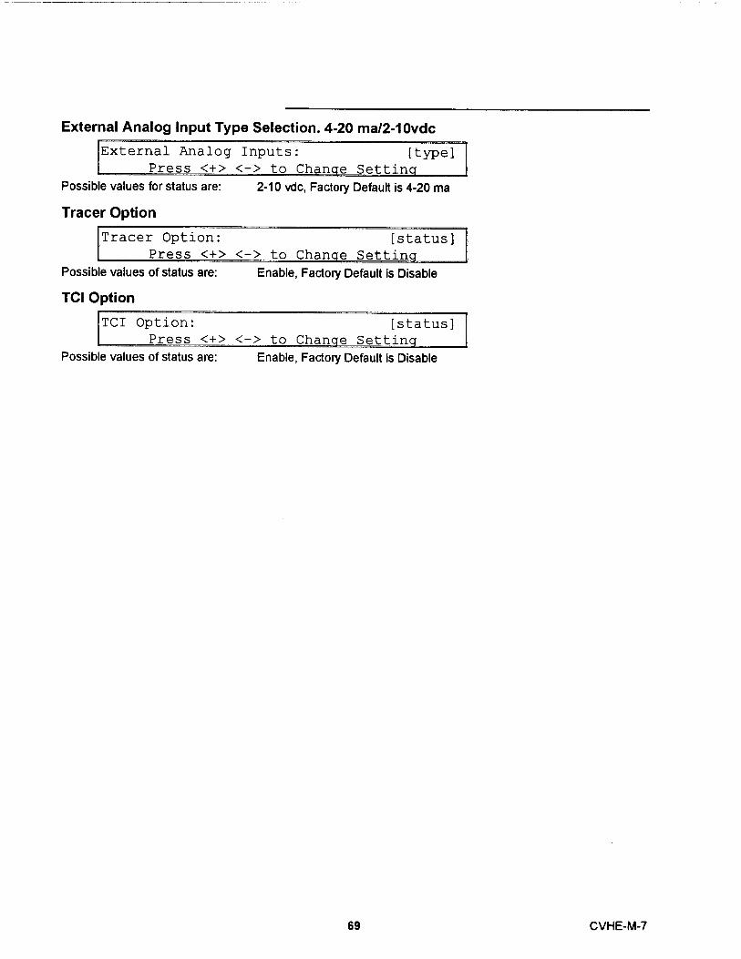
External Analog Input Type Selection . 4-20 ma/2-10vdc
External Analog Inputs: [type]Press <+> <-> to Change Setting
Possible values fo r status a re : 2- 10 vdc , Factory Default is 4-20 ma
Tracer Option
Tracer Option:
Press <+:
Possible values of status are :
TCI Option
TCI Option:
[status]
-> to Change Setting
Enab le , Factory Default is D isable
[status]11 Press <+> <-> to Change Settina
Possible values of status a re : E nab le , Fa ctory Default is D isable
69 CVHE-M -7
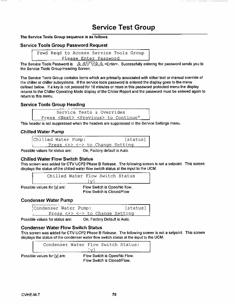
Service Test GroupThe Service Tests Group sequence is as follows :
Service Tools Group Password Request
Pswd Reqd to Access Service Tools Group
The Service Tools Password is AAVVAA <Enter> . Successfully entering the password sends you tothe Service Tools Group Heading Screen .
The Service Tools Group contains items which are primarily associated with either test or manual override ofthe chiller or chiller subsystems. If the service tools password is entered the display goes to the menudefined below. If a key is not pressed for 10 minutes or more in this password protected menu the displayreturns to the Chiller Operating Mode display of the Chiller Report and the password must be entered again toreturn to this menu.
Service Too ls Group Heading
Service Tests & Overrides
Press <Next> <Previous> to Continue"
This header is not suppressed when the headers are suppressed in the Service Settings menu .
Chilled Water Pump
Chilled Water Pump: [status]
Press <+> <-> to Change Setting
Possible values for status are : On , Factory default is Auto .
Chilled Water Flow Switch StatusTh i s screen was added for CTV UCP2 Phase B Release . The follow i ng screen is not a setpoint . This screen
d isplays the status of the chilled water flow switch status at the input to the UCM .
Chilled Water Flow Switch Status
[v]Possible values for [y] are :
Condenser Water Pump
Flow Switch is Open/No flow.Flow Switch is Closed/Flow
Condenser Water Pump: [status]
Press <+ > <-> to Change Setting
Possible values for status are : On , Factory Default is Auto .
Condenser Water Flow Switch StatusThis screen was added for CN UCP2 Phase B Release . The following screen is not a setpoint . This screendisplays the status of the condenser water flow switch status at the input to the UCM .
Condenser Water Flow Switch Status:
[v]Possible values for [y] are : Flow Switch is Open/No Flow.
Flow Switch is Closed/Flow.
CVHE-M-7 70

Starter Dry RunUse the following screen when [XX] _"Disabled".
St arte r Dry Run:
Press <+> <-> to Chanae Se-Use the following screen when [XX] Not equal to " Disabled"
Starter Dry Run:<+> <-> <Ente:
Poss i b le values for [XX] are :
>: Trans Compl Inp: (
D isabled ; Factory Defau ltShort i ng Re lay OnRun Relay OnStart Relay OnTransition Relay OnSta rt and Trans itio n Relays On .
[XX]
[XX]
Possible values for [Y] are : Closed This denotes that the Trans ition Complete input is seeing acontact closure .
Q= This denotes that the Trans ition Complete input is seeing acontact open .
If the un it is not in the local stop mode the following is disp layed .
Starter Dry Run, DisabledUnit Must Be In Stop To Activate Test
Oi l Pump
110il Pump: [status]
Possible values for status are On , Factory Default is Auto .
Vane Control StatusNane Position CommandsThe status of the Vane Control is as fol lows :
Vane Control Is: [status]Press <+> < > to Chanae Setting
The possible values of [status] a r^- Manua l, Factory default is Auto .If the vane control status is "AutL re fo l low i ng is disp l ayed :
Inlet Guide Vane Yosition: XXX.X % Open
[ limit mode
If the vane control status is "Manual" the fo llowing is displayed . When the Vane Control Status is transitionedfrom "Auto" to "Manual" , the manua l ta rget is i nitia li zed to the cu rrent vane posit ion .
Vane Pos XXX.X %
[limit model <+> ^
The poss i ble values of [li mit mode] are :
Target XXX.X % Open
-> to Chancre Taraet
Current LimitCondenser LimitEvap LimitBlank
71 CVHE-M-7

Vane Position
This screen was added for CTV UCP2 Phase B Release.
Inlet Guide Vane Position: XXXXX stepsT... l .. J- !" . . 4 A .. T T-. .-. .. T] - `. i+- i i. v. . VV V r^ ^ rr r ^ ^ e
CVHE-M-7 72
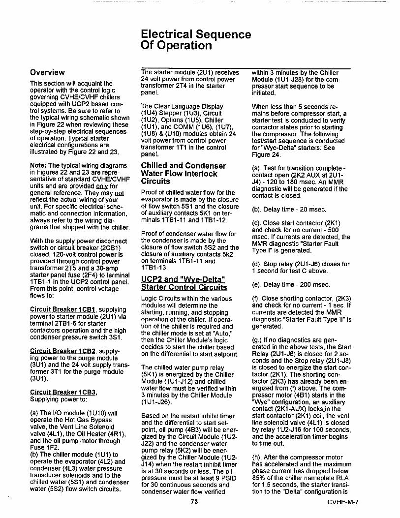
Overview
This section will acquaint theoperator with the control logicgoverning CVHE/CVHF chillersequipped with UCP2 based con-trol systems. Be sure to refer tothe typical wiring schematic shownin Figure 22 when reviewing thesestep-by-step electrical sequencesof operation. Typical starterelectrical configurations areillustrated by Figure 22 and 23.
Note: The typical wiring diagramsin Figures 22 and 23 are repre-sentat ive of standard CVHE/CVHFunits and are provided " forgeneral reference . They may notreflect the actua l wiring of yourunit . For spec ific electrical sche-matic and connection information ,always refer to the wiring d ia -grams that shipped with the chil ler.
With the supply power disconnectswitch or circuit breaker (2CB1)closed, 120-volt control power isprovided through control powertransformer 2T5 and a 30-ampstarter panel fuse (2F4) to terminal1T61-1 in the UCP2 control panel.From this point, control voltageflows to:
Circuit Breaker 1CB1 , su pplyingpower to starter module (2U1) viaterminal 2T61-6 for startercontactors operation and the h ighcondenser pressure switch 3S1 .
Circuit Breaker 1 CB2 , supply-ing power to the purge module(3U1) and the 24 volt supply trans-former 3T1 for the purge module(3U1) .
Circ uit Breaker 1 C63 ,Supplying power to:
(a) The I/O module (1 U10) willoperate the Hot Gas Bypassvalve, the Vent Line Solenoidvalve (4L1), the Oil Heater (4R1),and the oil pump motor throughFuse 1 F2.(b) The chiller module (1U1) tooperate the evaporator (4L2) andcondenser (4L3) water pressuretransducer solenoids and to thechilled water (5S1) and condenserwater (5S2) flow switch circuits.
Electrical SequenceOf Operation
The starter module (2U1) receives within 3 minutes by the Chiller24 volt power from control power Module (1 U1-J28) for the com-transforrner 2T4 in the starter pressor start sequence to bepanel. initiated.
The C lear Language Display(1 U4) Stepper (1 U3) , Circuit(1 U2) , Options (1 U5) , Chiller(1 U1) , and COMM (1 U6) , (1 U7) ,(1 U8) 8(U10) modules obtain 24volt power from control powertransformer 1T1 in the controlpanel .
When less than 5 seconds re-mains before compressor start , astarter test is conducted to verifycontactor states prior to startingthe compressor . The followingtest/start sequence is conductedfor "Wye-Delta" starters : SeeFigure 24 .
Chilled and CondenserWater Flow InterlockCircuits
Proof of ch i lled water flow for theevaporator i s made by the closureof flow sw itch 5S1 and the closureof auxiliary contacts 5K1 on ter-minals 1T61 - 11 and 1T61-12 .
Proof of condenser water flow forthe condenser is made by theclosure of flow switch 5S2 and theclosure of auxiliary contacts 5k2on terminals 1T61-11 and1 T61-13.
UCP2 and "Wye-Delta"Starter Control Circuits
Logic Circuits w ithin the variousmodules will determine thesta rt i ng , ru n n ing, a n d stopp i n gopera tion of the ch i ller . If opera-tion of the chiller i s requ i red andthe chiller mode is set at "Auto ,"then the Chiller Module 's logicdecides to start the chiller basedon the differential to start setpoint .
The ch i l l ed water pump re l ay(5K1) is energized by the ChillerModule (1U1 -J12) and ch i lledwater flow must be verified within3 mi nutes by the Chiller Module(1 U 1-J26) .
Based on the restart inhibit timerand the differential to start set-point, oil pump (4B3) will be ener-gized by the Circuit Module (1 U2-J22) and the condenser waterpump relay (5K2) will be ener-gized by the Chiller Module (1 U2-J14) when the restart inhibit timeris at 30 seconds or less. The oilpressure must be at least 9 PSIDfor 30 continuous seconds andcondenser water flow verified
73
(a) . Test for trans it ion complete -contact open (2K2 AUX at 2U1-J4) - 120 to 180 msec . An MMRd i agnostic will be generated if thecontact is closed .
(b) . Delay time - 20 msec.
(c) . Close start contactor (2K1)and check for no current - 500msec . If currents are detected , theMMR diagnostic "Starter FaultType I" is generated .
(d) . Stop relay (2U1-J6) closes for1 second for test C above .
(e) . Delay t ime - 200 msec .
(fl. Close shorting contacto r, (2K3)and check for no current - 1 sec . Ifcurrents are detected the MMRd iagnostic "Starter Fault Type II " isgenerated .
(g.) If no diagnostics are gen-erated in the above tests, the StartRelay (2U1-J6) is closed for 2 se-conds and the Stop relay (2U1-J8)is dosed to energize the start con-tactor (2K1). The shorting con-tactor (2K3) has already been en-ergized from (0 above. The com-pressor motor (4B1) starts in the"Wye" configuration, an auxiliarycontact (2K1-AUX) locks in thestart contactor (2K1) coil, the ventline solenoid valve (4L1) is closedby relay 1 U2-J16 for 100 seconds,and the acceleration timer beginsto time out.
(h). After the compressor motorhas accelerated and the maximumphase current has dropped below85% of the chiller nameplate RLAfor 1.5 seconds, the starter transi-tion to the "Delta" configuration is
CVHE-M-7

initiated.
(j) . The transition contactor (2K4)is closed through relay 2U1-J14,placing the transition resistors(2R1, 2R2 and 2R3) in parallelwith the compressor motor wind-ings ..
(k). The shorting contactor (2K3)is opened through the opening ofrelay 2U1-J12 100 msec after theclosure of the transition relay 2U1-J14.
(I . ) The run contactor (2K2) isclosed through relay 2U1-J10shorting out the transition resistors260 msec after the opening of theshorting relay 2U1 -J12 . Thisplaces the compressor motor inthe "Delta" configuration and themicro waits to look for this transi-tion for 2 . 35 seconds through theclosure of the transition completecontacts (2K2-AUX) at 2U1-J4 .
(m). The micro must now confirmclosure of the transition completecontact (2K2-AUX) within 2.5seconds after the run relay (2U1-J10) is closed. Finally, the transi-tion relay (2U1-J14) is opened de-energizing the transition contactor(2K4) and the compressor motorstarting sequence is complete. AnMMR diagnostic will be generatedif the transition complete contacts(2K2-AUX) do not close. A dia-gram of this test/start sequence isshown in Figure 24.
Now that the compressor motor(4B1) is running in the "Delta" con-figuration, the inlet guide vaneswill modulate, opening and closingto the chiller load variation byoperation of the stepper vanemotor acuator (4B2) to satisfychilled water setpoint. The chillercontinues to run in its appropriatemode of operation: Normal, Soft-load, Limit Mode, etc.
If the chilled water temperaturedrops below the chilled water set-point by an amount set as the"differential to stop" setpoint, anormal chiller stop sequence isinitiated as follows:
(a ). The inlet guide vanes a re
driven closed for 50 seconds. to recalibrate the zero position(Steps) of the Stepper motor vane
(b). After the 50 seconds has acuator. An inlet guide vaneelapsed, the stop relay (2U1-J6) stroke test is conducted for BPIand the condenser water pump (Binary Position Indicator) Positionrelays (1 U1-J14) open to tum off on all resets (hardware andthe compressor motor (4B1) and software) if there has not been athe condenser water pump. The Momentary Power Loss. This isoil pump motor (463) will continue also done if there is a call forto run for 2 minutes post lube cooling or heating condi- tion andwhile the compressor coasts to a it has been 24 hours or morestop. The chilled water pump will since the last BPI test and therecontinue to run while the chiller has not been a Momentary Powermodule (11.11) monitors leaving Loss for 5 minutes. See Figure 25chilled water temperature pre- for BPI operation.paring for the next compressormotor start based on the "differen- Note: The closed range of the BPItial to start" setpoint. If the STOP must straddle the factory pro-key is pressed on the human grammed 90 degree Vane Posi-interface, the chiller will follow the tion.same stop sequence as aboveexcept the chilled water pump Circuit Breaker 1 CB3 Oilrelay (1 U1-J12) will also open and Pumpstop the chilled water pump afterthe chilled water pump delay timerhas timed out after compressorshut down .
If the STOP key is pressed twicein rapid succession, twice within 5seconds, a "panic stop" is initiatedwhich follows the same stop se-quence as pressing the STOP keyonce except the inlet guide vanesare not sequenced closed and thecompressor motor is immediatelyturned off.
Vane Actuator Control
The 1 U3 Stepper Module pulses aDC voltage to the wind i ngs of the4B2 Stepper Module Vane Actu-ator to control inlet guide vanepos ition .
While operation of this steppermotor is automatic, manual controlis possible by going to the VaneControl StatusNane PositionCommands screen in the ServiceTests Menu and changing the"Target" value.
Note: If the chiller is operating in alimit mode (i.e. current limit, con-denser limit, evaporator limit, etc.)The limit operation has priorityover all manual modes of opera-tion.
On each UCP power-up, the inletguide vanes are driven full closed
Circuit Breaker 1 CB3 115-Voltcontrol power from control powertransformer 2T5 flows throughbranch circuit breaker 1CB3 andTerminal 1TB1-6 to a 6.2 ampfuse (1 F2). Fuse 1 F2 protects theoil pump motor (4B3) from overamperage conditions.
Current passing through Fuse 1 F2reaches 2 normally-open, parallelsets of contacts, those of oil pumprelay 1 U2-J22 and start contactor2K1-AUX
Note: While the 1 U2-J22 Relay 13automatically closed by 1 U2 as apart of the start sequence, it canalso be closed manually bychanging the Oil Pump status to"ON" in the Service Tests menu.
Closure of the 1 U2-J22 contactsalso allows current to passthrough the coil of oil pump starterrelay 4K8 to the "run" windings ofoil pump motor 4B3.
When motor 463 first starts, cur-rent draw is high; this causes cur-rent-sensing relay 4K8 to close itsnormally-open contacts and "pullin" of pump capacitor4C1. Withthis circuit complete, current nowflows to the "start" windings of theoil pump motor.
As the pump motor accelerates ,its amps draw eventually falls
CVHE-M-7 74

0m
V
N
:- ^
e ^sxt Bl dt xlB^
29}
^ ^(iiNSZ^oni)e
41-
11
^TT { ^^ zos. .zza z „^ ^.o 4a1 --
i rt
zc ^Kr
^^ I 2ns ^rca ^
L^ ^2
2U1^ ' • 115 Y. ^
F srue hn M o o iu =
Jl
c .xi canax P2
2 e vnc J 7
_.^)II v^ f ^nonn ^j
P 3B^I ) s 3
exe - cx( oanoxai ) ^ rs
P3C ^*T^* J4
P .^m oxa y
- sAll
*or annv J6
* PS A ^S .nn J 8o il oF .
P5BI)
Jvx e wnr^r+ r
J1 0
xnx
^ xn , c c o.i nccN r J1 2
J14
'RE
::'
5 aua^h
s 5 °
P tl
0
l. , 9 X^a oe^CNP re a v O e-en mrye ee
u.Noy tu< g Ccmv^ess u r ^ u n . t v rzun g U n^ lsnul^m^
t o SM1 UIam
rima ^
_.vq -
I-^
E .e^t s S t .rl ` uo aui o te i cv t o soN ary S etpa^t
^ ^ ^ t '^ ^^ se t t o ^ 0
5o S ec w^as
rme2 -.1- -1-.. ^
^- aa^tmi e^ IJ a unuhs ^.
ee.
o"Oi a'REL-
pwEi«ena+agN
ARE
COlS RE n0 i S NUxH - 1RO LLEO
Figure 22 S"U nit Mounte d Wye-De lta Sta rte r CVHE, CVHF ,„W,,,„^ Rr aE
cw rncroa
dWARNING
,tAVE RTISSEM ENT
u IMPORTANT
CVHE-SW-4008C

0
m
44
W
^-
3= -
» -
"-..1, ..1.
-_ ="i^---- -
wEra- -.E S.aA.R
- uxca+ma rnnaawiz
x vnrc ^
aaovmcner ws. iio-- -- ---- oAswco uHES mmurc vnwwE er owEas
zu1
^ ^ ca.iuw cnn a n
z a w c , I ?
F '3 A
II a H ' n - B v(wna+ul L^ 5
P3B„ II s J 3
s r e c^ ( ro ncMnij•s
P3C
p II vH C a3
^sEoana+u)
Ljva r J6
s .nrs. xn ^r J8
• P 5 A rvas [ n wRrs FN r sEE rsi rz e
J S• P56 nsE e -r
2 11 • P SC ng I cuRxcx r
^-
N=
aEs
41-
r s 1-4,...r^:
2-1 TI
IT.
]^IPZ
J
01 002 1-1
^ re
ONELo 3J_ N- vrsE 5 svnrw
s cc uE ^ z ^
..^_.^ _ re af{^O
r,,- s.a,.- or av^aua. NO, .-uxe st-
oISEia.Rwa.e
..,e
O^.^,.
Q^e w
o^^ 3 m^ t o . ... ..L.r ,na. oe - nv^
.^ e
^ cw ,eo. c^rv.ea
om"a,
LY'E- L o^a^e ^Ov A =a ,,,r =«- -fi0^._..E EL.A E-,S--
G^:'^^. 50
rm, 2 -.-
,o =^E.e.,, ^-o Oo, o.^^^^ L oo a^ o,_E.^ne aO^, _,^e
Figure 23Remote Across the Line Sta rte r
TI^RE= WRI,G o1111.1 ^ =PEaFIE^l.ft =^,7 -.""S
`N-A7217!,,,",'.^x ^r^^ H n^,^;H
x oLLauIn^^sEu roowExns^ocaco^RA11
1-1E rllnE uUUBER . A UIUEHLMEO wJYBER NC0.1E5
UNITTHE L1 NESiaai[rR^'MAING BEIMEFN
-^
STARLERIIiACNES_
OI0.GHAM ^ONYE
NN IONTACTS ARCCN1uGLLERSEE
iRaLLEO
Nmwao ^c"W,:"^^,uEa MOST at
^ Szaan . iez ^w
i,e,-zb
a
^WARWNG
aAVERTISSEM ENT
IMPORTANT
NIT
CVHESW4OOOC
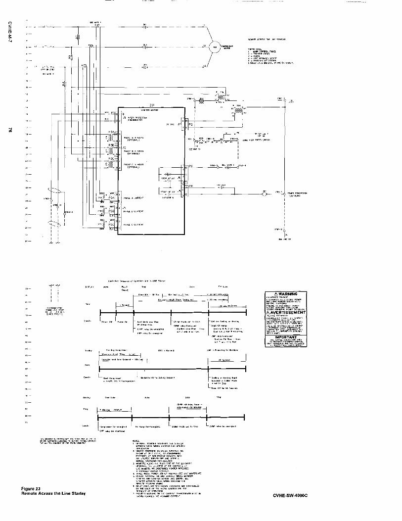

Figure 24UCP2 Test/Start Timing Sequence
^ ' ctosedi. ^--- G
Start Opc n
C tase d
Stop^D
Open
Closed
Run , Open
Closed
Short E I'<-- Open
^E--F-^' Closed
Transition Open
Closedosed
Comple te Open
-^ B E-- > J F^Input
I{A'
H L F
M.F-
Maximum Phase Curre nt<or=to85 %RLA
Interval Minimum Maximum Units Actual Design
A (Test for transition 120 to 180 mseccomplete in put open)
B (Just delay time) 20 msec
C (Close 2Kt Contactor 500 msecand test for no current.)
D(Close Stop Relay and 1 sectest for no current.)
200 msec
E(Just delay time) 1.0 sec (Min.)
F (Close shorting con- 100 (1) msecta ctor and te st for nocurrent, then wa it forStart command.
G 2.0 sec 2 sec
H(Wait 1.5 sec after drop 1 2 sec 1.5 secto 85% to transition)
J 85 100 msec 100 msec
K 250 300 msec 260 msec
L(Waft to look for transi- (2) msec 2.32 to 2.38tion complete)
M(Fittering time on tran- (2) msec 120 to 180 msecsition complete input.)
Notes:
(1) This time period must be long enoughto verify the absence of phase currentscaused by the closing of the "Short"contacts.
(2) The sum of intervals L and M aredesigned to be 2.5 seconds.
77 CVHE-M-7
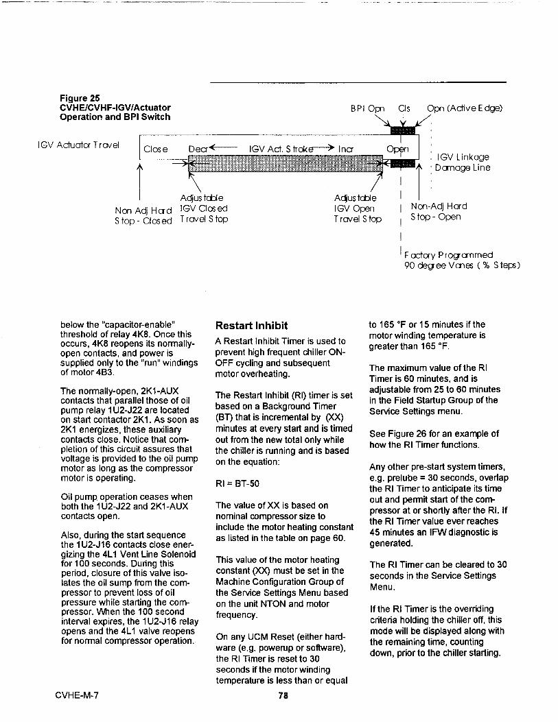
Figure 25CVHEICVHF-IGV/ActuatorOperatior, and BPI Switch
B P I Opn CI s
IGV Ach.iator Trav el I Close DeaF- IGV Act. Stroke-> Ina
A `7M
Adjus tcble
N on Adj H a d I GV CI os ed
S top - Closed T ravel S top
Restart Inhibit
Opn (Active Edge)
OpgnIGV Linkage
A Damage Line
Non-Adj HardS top - Open
F acFory P rogrammed90 degee Vmes (% S teps)
below the "capacitor-enable"threshold of relay 4K8. Once thisoccurs, 4K8 reopens its normally-open contacts, and power issupplied only to the "run" windingsof motor 4B3.
The normally-open, 2K1-AUXcontacts that parallel those of oilpump relay 1 U2-J22 are locatedon start contactor 2K1. As soon as2K1 energizes, these auxiliarycontacts close. Notice that com-pletion of this circuit assures thatvoltage is provided to the oil pumpmotor as long as the compressormotor is operating.
Oil pump operation ceases whenboth the 1 U2-J22 and 2K1-AUXcontacts open.
Also, during the start sequencethe 1U2-J16 contacts close ener-gizing the 4L1 Vent Line Solenoidfor 100 seconds. During thisperiod, closure of this valve iso-lates the oil sump from the com-pressor to prevent loss of oilpressure while starting the com-pressor. When the 100 secondinterval expires, the 1 U2-J16 relayopens and the 4L1 valve reopensfor normal compressor operation.
Adjus tcbeI GV OpenTravel Stop
A Restart Inhibit Timer is used toprevent h igh frequent chiller ON-OFF cycling and subsequentmoto r overheating .
The Restart Inhibit (RI) timer is setbased on a Background Timer(BT) that is incremental by (XX)minutes at every start and is timedout from the new total on ly whilethe chiller is running and is basedon the equation :
RI = BT-50
The value of XX is based onnominal compressor size toinclude the motor heating constantas listed in the table on page 60 .
This value of the motor heatingconstant (XX) must be set in theMachine Configuration Group ofthe Service Settings Menu basedon the unit NTON and motorfrequency.
On any UCM Reset (either ha rd-ware (e . g . powerup or software) ,the RI Timer is reset to 30seconds if the motor windingtemperature is less than or equal
to 165 OF or 15 minutes if themotor wind i ng temperature isgreater than 165 O F .
The maximum value of the RITimer is 60 minutes , and isadjustable from 25 to 60 minutesin the Field Startup Group of theService Settings menu .
See Figure 26 for an example ofhow the RI Timer funct ions .
Any other pre-start system timers ,e . g . prelube = 30 seconds , overlapthe RI Timer to anticipate its timeout and permit start of the corr^pressor at or shortly after the RI . Ifthe RI Timer value ever reaches45 mi nutes an IFW diagnostic isgenerated .
The RI Timer can be cleared to 30seconds in the Service Sett i ngsMenu .
If the RI Timer is the overridingcriteria holding the chiller off, thismode will be displayed along withthe remaining time , countingdown , prior to the chiller starting .
CVHE-M-7 78

Figure 26CVHE/CVHF - UCP2 Restart Inhibit Timer
Parameter CVHE/CVHF
Background Timer Increment on Start (Motor Heating Constant) Adjustable, 25 Min. Fac. Dflt.
General RI Timer Setting RI = BT -50 M inutes
Minimum RI Timer Setting 30 Seconds
Maximum RI Timer Setting 60 Minutes
Adjustment Range of Maximum RI Timer Setting 30 to 60 Minutes
Winding Temperature Decisio n PoinUR l Timer Above this Temp. a fter Reset 165 F(73.8C)/15 Minutes
IFW Diagnostic Threshold RI Timer = 45 Minutes
i 2a-
^
m
- sa
1 . Unit started and ran 10 min ., BTincremented 30 Min ., and decreased by 10min . RI = (30-10) - 50 = -30 .2 . Unit restarted RI = -30 , BT incrementedanother 30 min ., unit ran 10 m i n . and BTdecreased by 10 min . RI = (50-10) - 50 = - 103. Unit restarted RI = -10 , BT incrementedanother 30 min ., unit ran 10 min . and BTdecreased by 10 min ., RI = (70-10) - 50 = 10 .4 . Unit Restart Inhibit is 10 min . from (3) .5. Unit restarted after 10 min . RI in (4) , BTincremented another 30 min ., unit ran 10 min .and BT decreased by 10 min . RI = (90- 10) -50= 30 .6. Unit restart i s 30 min . from (5).7 . Un it restarted after 30 minute RI min ,(6) , BT incremented another 30 min ., and unitran for 110 min ., and BT goes to zero .
Notes :1 . 30 second/15 minute restart inhibit
due to motor winding temperature noti ncluded .
2 . Examp l e for Motor Heating Constant= 30
3 . If calculated RI is negative then RI = 0 .
79 CVHE-M-7

Controls
Chilled Water Reset (CWR)
Chilled water reset is designed forthose applications where thedes ign chilled water temperatureis = required at partload . Inthese cases , the leaving chilledwater temperature setpoint can bereset upward using the CWRfeature .
When the CWR function is basedon return water temperature , theCWR feature is standard . Whenthe CWR function is based onoutdoor air temperature , the CWRfeature is an option requiring anoutdoor temperature sensor andthe Options Module i nsta l led in theUCP2 panel .
The type of CWR is selectable inthe Operator Settings Menu alongwith the Reset Ratio, Start ResetSetpoint, and the Max ResetSetpoint.
The following equations and RESET RATIO is a user adjus-parameters apply for CWR. table gain
Return
CWS' = CWS + RATIO (STARTRESET - TWE - TWL)and CWS' >or = CWSand CWS' - CWS<or = MaximumReset
Outdoor
START RESET is a useradjustable reference
TOD is the outdoor temperature
TWE is entering evap . watertemperature
TWL is leaving evap . watertemperature
CWS' = CWS + RATIO * (STARTRESET - TOD)and CWS' >or = CWSand CWS' - CWS<or = MaximumReset
Where
CWS' is the new chilled watersetpoint
CVNS is the active chilled watersetpoint before any reset hasoccurred
Table 4 - Values for Star Reset Types
The values for "RESET RAT I O " for each otthe reset types are :
MAXIMUM RESET is a useradjustable limit providing themaximum amount of reset . For alltypes of reset , CWS ' - CWS < or =Maximum Reset .
The values for "Sta r Reset " foreach of the reset types are shownin Table 4 .
Reset Reset Increment Increment FactoryType Ratio English SI Units DefauR
Range Unds Value
Return 10 to 120% 1% 1% 50%Outdoor 80 to -80% 1% 1% 10%
Reset Start Increment Increment FactoryType Reset En l ish SI Uni ts DefauR
Range Un^s Value
Return 4 to 30 F 1 F 0 . 1 C 10 F (5 . 6C)2.2
o130.F C) 1 F 0 . 1 C 90 F (32 . 2C)
(10 to 54 . 4 C)
The va lues fo r MAX IMUM RESET fo r ea ch of the reset types a re :
Reset Maximum Increment Increment FactoryType Reset English SI Units Defauft
Range Unds Value
Return 0 to 20 F 1 F 0 . 1 C 5 F (2 . 8 C)
(0 . 0 to 11 . 1 C)
Oto20F 1 F 0 . 1 C 5 F(2 .8C)
Outdoor (0 . 0 to 11 . 1 C )
CVHE-M-7 80
Both Return and Outdoor Resetdo not apply to heat Pump Modewhere the UCP2 is controlling theLeaving Condenser WaterTemperature .
Constant Return Reset will resetthe leaving water temperaturesetpoint so as to provide a con-stant entering water temperature.The Constant Retum Resetequation is the same as theReturn Reset equation except onselection of Constant ReturnReset, the UCP2 shallautomatically set RATIO, STARTRESET, and MAXIMUM RESETto the following.
Differential To Start/Stop
The Differential to Start setpoint isadjustable from 1 to 10 0 F (0 . 5 to5 . 55 C) and the Differential toStop setpoint adjustable from 1 to10° F (-0 . 5 to -- 5 . 55C) . Bothsetpoints are with respect to theAct ive Chilled Water Setpo i nt anda re set i n the Service Settingsmenu .
When the chiller is running andthe LWT reaches the Differentialto Stop setpoint the chiller will gothrough its shutdown sequence toAUTO .
Leaving WaterTemperature Cutout
violate the above minimumdifferences and the "LeavingWater Temperature CutoutSetpoint" remains at its currentsetting. When the "Leaving WaterTemperature Cutout Setpoint" isadjusted upward, the aboveminimum difference is not violatedand as the "Leaving WaterTemperature Cutout Setpoint" isadjusted upward the chilled watersetpoint, both active and frontpanel, is raised to maintain theminimum difference.
After violation of the "LeavingWater Temp . Cutout Setpoint" for30 ° F seconds the chi l ler w i llshutdown and indicate adiagnostic .The RATIO = 100%
The START RESET = DesignDelta Temp .The MAX IMUM RESET = Des ignDelta Temp .
The equation for Constant Retumis then as follows:
Constant Return
CWS' = CWS + 100%(Design Delta Temp. -WE - TVVL))
and CWS'> or = CWSand CWS' - CWS<or =Maximum Reset
Notice that Constant Return isnothing more than a specific caseof Return Reset offered foroperator convenience .
When any type of CWR isenabled, the UCP2 will step theCWS toward the desired CV11S'(based on the above equationsand setup parameters) at a rate of1 degree F every 5 minutes untilthe Active CWS equals thedesired CWS'. This applies whenthe chiller is both running and notrunning. The chiller will start at theDifferential to Start value above afully reset CWS or CV11S' for bothReturn and Outdoor Reset.
Leaving water temperature cutoutis a safety control that protects thechiller from damage caused bywater freezing in the evaporator .The cutout setpoint is adjustablein the Service Settings Menu .
For freeze protection from lowleaving water temperatures theUCP2 provides a low leavingwater temperature cutout basedon leaving water temperature . The"Leaving Water TemperatureCutout Setpoint" is independentlyadjustable from the chilled watersetpoint and factory set . Shutdownof the compressor due to violationof the Leaving Water TemperatureCutout results in an automaticallyresettable diagnostic (MAR) .
The UCP2 indicates when the"Leaving Water TemperatureCutout Setpoint" conflicts w ith thechilled wate r temperature setpo i ntby a message on the display . The" Leaving Water TemperatureCutout Setpoint " and ch il led watersetpoint , both acti ve and frontpanel , are separated by am inimum of 1 . 7 ° F . (See CutoutStrategy F igure 27) . When e itherdifference is violated the UCP2does not pe rmit the aboved ifferences to be violated and thed isplay d isplays a message to thateffect and rema i ns at the last validsetpo i nt .
Low RefrigerantTemperature Cutout
Th i s i s a safety funct ion thatprevents water in the evaporatorfrom freez i ng due to lowevaporator refrige ranttemperatures . When the trip pointis violated , the ch i ller will shutdown and display a latchingdiagnostic (MMR) indicating theviolation . The cutout setpoint isadjustable i n the Service SettingsMenu .
The UCP2 indicates when the"Low Refrigerant Temp. CutoutSetpoint" conflicts with the chilledwater temperature setpoint by amessage on the display. The "LowRefrigerant Temp Cutout Setpoint"and chilled water setpoint, bothactive and front panel, areseparated by a minimum of 6° F(See Figure 27). When eitherdifference is violated, the UCP2does not permit the abovedifferences to be violated and thedisplay displays a message to thateffect and remains at the last validsetpoint.
When the chilled water setpoint,both active and front panel, isadjusted downward, it does not
81 CVHE-M-7

Figure 27Cutout Strategy
^niller: Water
Evap Leaving
Evap . Rfgt
Differentla l to Stop
Adjustment Range
X degrees Min imum D i fferential
2 deg rees F (1.1 C)
Cutout I 0. 5 degrei
In tegrate to Trip
F
Y d egrees Minim um Differen tial
C)2. 5 deg rees F (1.39 C)
Limit Loading Evap.
=-_Hold _ _:T_ _ L i mit
Unload
Evap Umit Stpt ^ -^- ~ -------,F-^`-
C utout I ntegrate to Tnp
F i gure " Cutout Strategy"
When the chilled water setpoint,both active and front panel, isadjusted downward, it does notviolate the above minimumdifferences, and the "LowRefrigerant Temp. CutoutSetpoint" remains at it's currentsetting. When the "LowRefrigerant Temp. CutoutSetpoint" is adjusted upward, theabove minimum difference is notviolated, and as the "LowRefrigerant Temp Cutout Setpoint"is adjusted upward, the chilledwater setpoint, both active andfront panel, are raised to maintainthe minimum difference.
After violation of the "LowRefrigerant Temp. CutoutSetpoint" for 30 ° F - seconds, thechiller will shutdown and indicate adiagnostic.
Enhanced CondenserLimit Control
When the chiller is running inCondenser Limit Mode or in SurgeMode, the head relief requestrelay on the Options Module(1 U5-J12) will be energized andcan be used to control or signal fora reduction in the enteringcondenser water temperature.
Designed to prevent highrefrigerant pressure trip-outsduring critical periods of chilleroperation, this UCP2 optionconsists of:
1. Condenser Refrigerant Pres-sure Transducer (3R3).
2. The Options Module (1 US) withthe head relief request relay(1 U5 - J12).
3. Interconnecting Wiring
If the unit is not equipped with theEnhanced Condenser Limit Opt ion(3R31 US) the unit w i ll use thecondenser refrigerant temperaturesensor (input converted tosaturated refrigerant pressure) toperform the Standard CondenserLim it function , without the headrel i ef request relay , by limiting inletguide vane stroke and chillercapacity .
Keep i n mind that the UCP2Condenser Limit Controlsupplements the protectionprovided by the condenserpressure high pressure cutoutsw i tch 3S1 .
Free Cooling
As described in mechanicalOperation, this control optionadapts the basic chiller to functionas a simple heat exchangerwithout controlling leaving watertemperature.
To enable Free Cooling Mode :
CVHE-M-7 82

1. "Install" Free Cooling in the Ma-chine Configuration Menu.
2. Enable the Free Cooling modein the Operator Settings Menu to"ON" while the chiller is in"AUTO", or
3 . C lose the external binary inputswitch to the Options Module1 U5-J3-5 and -6 if so equippedwhile the ch ill er is in "AUTO".
Free Cooling can not be entered ifthe ch i l l er is in "STOP".
If the chiller is in "AUTO" and notrunning, the condenser waterpump will start. After condenserwater flow is proven, relays at1U5-J16, 1U5-J20, and 1U5-J24will energize operating the FreeCooling Valves 4B12 and 4B13.The Free Cooling Valves EndSwitches must open within 3minutes, or an MMR diagnosticwill be generated. Once the FreeCooling Valves End Switchesopen, the unit is in the FreeCooling Mode.
If the chi ller is in AUTO andrunning powered cool ing , thech i ller w i ll do a friendly shut downfirst , (RUN : Unload , POST LUBE ,and drive vanes closed) . After thevanes have been ove rdriven ,closed and condenser waterproven , the Free Cooling relayswill be energized .
To disable Free Cooling andreturn to Powered Cooling, eitherdisable the Free Cooling Mode inin the Operators Settings menu ifused to enable Free Cooling or"OPEN" the external binary inputswitch to the Options Module if itwas used to enable Free Cooling
Once Free Cooling is disabled, theFree Cooling relays 1 U5-J16, and1 U5-J20 and 1 U5-J24 will de-energize allowing the Free Cool-ing valves to close. The FreeCooling valves end switches mustclose within 3 minutes or an MMRdiagnostic is generated.
Once the end switches close thechiller will return to "AUTO" andpowered cooling will resume if
there is a call for cooling based on determines the chiller to be shutthe differential to start. down, the inlet guide vanes will be
driven fully closed, and the HGBPOnce powered cooling has valve will be driven closed.resumed and the compressor has After the inlet guide vanes are fullystarted, the inlet guide vanes will closed the chiller will shut down inbe held closed for 3 minutes to the Friendly mode.allow for temperature/pressurestabilization .
Note: The manual control of theinlet guide vanes is disabled whilein the Free Cooling Mode and thecompressor is prevented fromstarting by the control logic .
Note: The relay at 1U5-J20 is aFC auxili ary relay and can beused as requ i red .
Hot Gas Bypass
The hot gas bypass (HGBP)control option is designed tominimize machine cycling byallowing the chiller to operatestably under minimum loadconditions. In these situations, theinlet guide vanes are "locked" at apreset minimum position, and unitcapacity is governed by the HGBPvalve actuator.
Control circuitry is designed toallow both the i nlet guide vanesand the HGBP valve to close forunit shutdown .
HGBP is enabled in the FieldStartup Group of the ServiceSettings Menus by enabling theoption and setting the HGBPCut-in Vane Position in the samemenu .
Afte r a ch i ller sta rts and is runningthe in l et gu ide vanes will passthrough the HGBP Cut-In Vanepositio n as the chille r starts toload . As the chiller catches theload and sta rts to unload , the inletgu ide vanes wi ll close to theHGBP Cut- In Vane posit i on . Atthis point the movement of theinlet guide vanes is frozen andfu rther unloading of the ch ill er iscontrolled by the opening of theHGBP Valve 4B5 by the 1 U10module . The 1U10 modulemodulates the HGBP valve at lowloads .
When the control algorithm83
Chillers with HGBP have adischarge temperature sensor(4RT6) monitoring the dischargegas temperature from theCompressor. If this temperatureexceeds 2000 F, the chiller willshut off on a MAR diagnostic. Thechiller will reset automaticallywhen this temperature drops 50° Fbelow the trip-point.
Unit Start-Up Procedures
Daily Unit Start-Up
1. Verify the chilled water pumpand condenser water pumpstarters are in "ON" or "AUTO".
2 . Verify the cool ing tower is in"ON" or "AUTO".
Note : Refer to Figure 28 for UCPStart-Run-Shutdown sequenceand UCP timing functions .
3. Check the oil tank oil level; thelevel must be visible in or abovethe lower sight glass. Also, besure to check the oil tank tem-perature; normal oil tanktemperature before start-up is 140° F to 145 ° F(60 to 63 C).
Note : The oil heater is energizedwhenever power is supp lied to theun it and the oil temperature is lessthan 140 0 F (60 C) .
4 . If the chiller is equipped with thefree cool i ng option , ensure thatthe free cooling option is disabledin the Operator Setti ngs menu .
5 . Check the chilled water setpointand readjust it , if necessary , in theOperator Settings menu .
CVHE-M-7

6 . If necessary , readjust the 2 . 5 -seconds of transition initiation , water boxes .current limit setpoint in the or un i t start- up is aborted . (If thisOperators Setting menu . occurs , the unit goes into the 4 . Open al l of the valves in the
post- lube mode , and a MMR evaporator chilled water circuit .7 . Press "AUTO". diagnost ic is generated .
The UCP also checks compressormotor winding temperature, and aminimum 30 second delay isinitiated if the winding temperatureis less than 165 ° F. If it is greaterthan 165 ° F, however, a15-minute delay period begins.The chilled water pump relay isenergized and evaporator waterflow is proven.
Next , the UCP checks the leavingevaporator water temperature andcompares it to the chilled watersetpoint . If the difference betweenthese values is less than the startd i fferential setpoint , cooling is notneeded .
If the UCP determines that thedifference between the evaporatorleaving water temperature andchilled water setpoint exceeds thestart differential setpoint , the unitenters the Initiate Start Mode andthe oil pump and the condenserwater pump are started .
If condenser water flow is notproven (i . e ., flow switch 5S3 doesnot close) within 3 minutes , theun it is locked out on a MMRDiagnostic .
Oil pressure must be verifiedw ithin 3 m i nutes or a MMRdiagnost ic is generated .
When less than 5 seconds remainon the restart inhibit, the pre-startstarter test is conducted onY-Delta starters. If faults aredetected, the unit's compressorwill not start, and a MMRDiagnostic will be generated.
After the pre-start Starter test , theUCP sends a start signal to thecompressor motor . Within 2-seconds , 3 phases of current inthe correct phase sequence mustbe detected . If there is no current ,1 or 2 phases missing , or reverseelectrical sequence , diagnosticsw i ll occur . Acceleration and proofof transition must occur within
If the compressor motor starts andaccelerates successfully, "Unit isRunning" appears on the display.At this time the purge unit will startoperating on "Automatic" and willcontinue to operate as long aschiller compressor is running.
Note: Whenever the UCP detectsa MMR diagnostic condition duringstart-up, unit operation is lockedout, and manual reset is requiredbefore the start-up sequence canbegin again. If the fault conditionhas not cleared, the UCP will ^tpermit restart.
When the cooling requirement issatisfied, the UCP originates a"Shutdown" signal. The inlet guidevanes are driven closed for 50seconds, and the unit enters a2-minute post-lube period. Thecompressor motor and condenserwater pump starter are de-energized immediately, but the oilpump continues to run during this2-minute interval; the evaporatorpump will continue to run.
Once the post- lube cycle iscomplete , the unit returns to theauto mode .
Seasonal Unit Start-Up
Note: Refer to Figure 28 for UCPStart-Run-Shutdown sequenceand UCP timing functions.
1 . Close all drain valves , andre-i nstall the drain plugs in theevaporator and condenserheaders .
2 . Service the auxiliary equipmentaccording to the start-up/main-tenance instructions provided bythe respective equipmentmanufacturers .
3. Vent and fill the cooling tower, ifused, as well as the condenserand piping. At this point, all airmust be removed from the system(including each pass). Then closethe vent valves in the condenser
5. If the evaporator was previouslydrained, vent and fill theevaporator and chilled watercircuit. When all air is removedfrom the system (including eachpass), close the vent valves in theevaporator water boxes.
6 . Lubricate the external vanecontrol linkage .
7 . Check the adjustment andoperation of each safety andoperating control .
8 . Close all disconnect switches .
WARNING: To prevent injury ordeath due to electrical shock orcontact with moving parts, usecare when measurements,adjustments, or other service-related operations areperformed with power on.
9 . Perform instructions l isted in"Daily Unit Start-Up" section .
Unit ShutdownProcedures
Daily Unit Shutdown
Note : Refer to Figure 28 for UCPStart-Run-Shutdown sequenceand UCP ti ming functions .
1 . Press STOP .
2 . After compressor shutdown turnPump Contactors to off or openpump disconnects .
Seasonal Unit Shutdown
Note : Refer to Figure 28 for UCPStart-Run-Shutdown sequenceand UCP timing functions .
1 . Press STOP .
2 . After compressor shutdown turnoff the chilled water pump at thepump's push - button station . (Or ,stop chilled water flow by themeans devised for this particularapplication . )
CVHE-M-7 84

Figure 28CVHE/CVHF - UCP Sequence/Timing
38 -
3 9 -
•0 -
s i -
` Z -
a }
a3 -
4 5 -
• 7
48 -
43 -
`A -
51 -
52 -
53 -
5. -
55 -
C e n T.oVOC SeQum c e of Op erolion With wrE-DEl7a 5la.t e .
D ISPl A 1' B Ia n4 Reset S to D A u l a P r e Wbe
(H Ord) Cloae I G V - 50 Sc: I GV T esl - 7 5 Se t < 30 s
<
5
TARTER
RE4AIN i NG
Re -slart Inh,bit Timer Timin g out < 30 s
Tim eI Second j SO Se c W nimum
E v ents ` p o „e r OflLPowr
OnLasl M o0e o s St op
o, vo . e. ioss
CH `hP rela y D e - e-giz e d
CWP rdoy D e -energ-d
O'svlar Star t i n g compresso r
Mo. i- Accel . Timer - 2 7 Sec .
E n e r i re Ve r t L ine Sol en oid - 1 00 Sec
Ti me
I
Cniuer mode set to Auto Can lor Coonng or Heoting
C}1 KP r e lay E-g i zed Sla rl Oi l P um p
Confi rm CHW flo . - I— Lo n firm 9 Ps i d Oi l Gr e ss -
ou t 3 mi n i t no fio . tim e o u t 3 mm i f n o v,e ss
CwP rd oy Energized
Con (irm C W ilor - t imeout
3 min It no no . .
g Uni t is P r epa ri ng t o Sh utdo wn
1 5 0 Stt a nd S
U nit is R u nn in
I
E-ts LS t o.l C omvrez sor
i n WYE Conf i g u ro4on
D + s ploy P o st L ub e
2 M- les - CW E /Fre
L Mo duia l e IGV to Sol i sfy S elp oi nt
A uto Stop
CHWP ol( d e l py timer -
adNS t a bl e 1- 30 Mi-l es
EvmtsLComp. essor D e -ereryii e d
LOiI Vump D e -En ergiz e d.
TM'S DFAVAHG 15 MCqRKTARY AND SM>LL NOT BE C O^ED CA9 re l ay Oe-e n ery i zeE
OR I T S CON TENTS D1 50.p$[D TO IX 1 fy0E PAPPE$ M MOl1TTH E MFI 7 TEN C ON SE NT OG IHE TR AHE COU P,v+Y
Cooling or Heat..g Ramt
Satisfie0 or Chill c r Al ode
is set to Stop
Close ICV for 50 Seconds
Stop
f
C hi ll er mode se t t o St o pL
CHN? .ela y D e - en er gi [ ed
CVHE-SW-4003C
85 CVHE-M-7

3. Open all disconnect switches Trouble Analysisexcept the control powerdisconnect switch .
WARNING: To prevent injury ordeath due to electrical shock orcontact with moving parts , usecare when servicing systemwith power on .
CAUTION : Control Powerdisconnect must remain closedduring entire shutdown periodto allow oil sump heateroperation . This preventsrefrigerant from condensing inoil sump.
4 . Drain the condenser piping andcooling tower , if used .
5 . Remove the drain and ventplugs from the condenser headersto drain the condenser .
6 . Once the un it is secured forwinter , the maintenanceprocedures descri bed under"Annual Maintenance " in thePeriod ic Maintenance sect ion ofthis manual should be performedby qualifi ed Trane servicetechnicians .
Note : Duri ng extended shutdown ,be sure to operate the pu rge unitfor a 2-hour period every 2 weeks .this w i ll prevent the accumulationof air and non-condensables in themachine . To start the purgechange purge mode to "ON" in theOperator Settings Menu .Remember to turn the purge modeto AUTO afte r the 2-hour run time .
CAUTION : Do not allow thech i ll er to increase i ntemperature pressure while theunit is off, to a temperatureabove 110 ° F (43C) since thiswi ll cause the rupture disk torelieve and discharge therefrigerant from the machine .Continuous running of pumpswhile the machine is off mayca use th is cond it ion to occ ur.The rupture disk is designed torelieve if the p ressure in theevaporator exceeds 15 ps ig .
If the red light on the control panelis flashing , an MMR diagnostichas occurred . See DiagnosticSection for trouble shootinginformation . The diagnostic mustbe analyzed , corrections made byqualified personnel and the MMRdiagnostic reset before the chillercan be returned to operation .
CVHE-M-7 86

Overview
This sect ion describes the basicchiller preventive maintenanceprocedures , and recommends thei ntervals at which theseprocedu res should be performed .Use of a periodic maintenanceprogram is important to ensure thebest possible performance andefficiency from a CenTraVacch i ller.
Recommended purgemaintenance procedures for thePurifier Purge unit are covered byPRG-OM-5
Periodic Maintenance
An important aspect of the chillermaintenance program is theregular completion of records.Provided at the end of this manualare copies of the "AnnualInspection Check List and Report","CenTraVac with UCP2Commissioning Checklist &
PeriodicMaintenance
Start-Up Test Log", a "Sta rt-Up and discharge oil pressure.Test Log for Water Cooled Compare the readings with theCenTraVacs with UCP2 Control values provided in Table 5 below.Panels" and "UCP2 "SettingsGroup" Menu Record". When filled CAUTION : If frequent purg i ng isout accurately by the machine required (i .e ., mon itor purgeoperator, the completed logs can pumpout rate) identify andbe reviewed to identify any correct source of air or waterdeveloping trends in the chiller's leak as soon as possible .operating conditions. Moisture contamina tion caused
by leakage can shorten chillerFor example , if the machineoperator notices a gradualincrease in condensing pressureduring a month's time , he cansystematically check , then correctthe possible cause(s) of thiscondition (e . g ., fouled condensertubes , non-condensibles in thesystem , etc . )
Daily Maintenance andChecks
life expectancy .
[] Check the oil level in the chilleroil sump using the 2 sight glassesprovided in the oil sump head.When the unit is operating, the oillevel should be visible in the lowersight glass.
Weekly Maintenance
[ ] Complete all daily maintenanceprocedures and checks.
( ] Check the chiller's evaporatorand condenser pressures , oil tankpressure , different i al oil pressure
Table 5Normal Chiller Operating Characteristics
Ope rating NormalCharacte ristic Reading
Evaporator Pressure 12" to 18" Hg (Vacuum)
Condenser Pressure 2 to 12 psig(See Notes 1 and 2 ) (standard condensers)
Oil Sump Temperature:Unit Not Running 140 to 1 45 F
(60 to 63 C)Unit Running 115 to 150 F
(47 to 66 C)
Differential Oil Pressure 12 to 1 8 psid
Notes:
1 . Condenser pressure is dependent on condenser water temperature , and should equa l
the saturation pressure of HCFC-123 at a temperature 5- 10 F (- 15 to - 12 C ) above
that of leaving condenser water at ful l load .
2 . Norma l pressure read i ngs for ASME condensers exceed 12 ps i g .
3 . Oil Tank Pressure 12" to 18" Hg
D i scharge Oil Pressure 7 to 15 ps i g
87 CVHE-M-7

Every 3 Months
WARNING : To prevent injury ordeath due to electrical shock orcontact with moving parts , lockunit disconnect switch in openposition .
[ ] Complete all recommendedweekly maintenance procedures .(Refer to the previous sect ions fordetails .
[] Clean all water strainers in theCenTraVac water piping system .
Every 6 Months
WARNING: To prevent injury ordeath due to electrical shock orcontact with moving parts, lockunit disconnect switch in openposition.
[ ] Complete all recommendedquarterly maintenance pro-cedures .
[ ] Lubricate the vane controllinkage bearings , ball joints , andpivot points ; a few drops of lightmachine oil (e .g ., SAE-20) issufficient .
[] Drain the contents of therupture d isc/purge discharge vent-line drip-leg , into an evacuatedwaste container minimumly andmore often if the purge is operatedexcessively .
Also , apply 1 or 2 drops of oil onthe vane operator shaft andspread it into a very light film ; thiswill protect the shaft from moistureand rust .
Off-Season Maintenance
During those periods of time whenthe chiller is not operated , be surethe control panel is energized .
Annual Maintenance
Shut down the chiller once eachyear to check the items listed be-low; a more detailed inspectionchecklist is provided on the "ModelCVHE/ CVHF CenTraVac Annual
Inspection Checklist and Report" [] Pump the oil from the chillerillustrated in this manual. through the oil charging valve into
an air-tight resealable container,[] Perform the annual main- using a magnetically-driventenance referred to in the Main- auxiliary pump.tenance Section of the purgemanual .
[ ] Use an ice water bath to verifythat the accuracy of the evap-orator refrigerant temperaturesensor (4RT5) is still w ithintolerance (i . e ., + 2 . 0 ° F at 32 ° F) .
If the evaporator refrigeranttemperature displayed on theUCP 's read-out is outside this4-degree tolerance range , replacethe sensor.
Note : If the sensor is exposed totemperature extremes outside itsnormal operat i ng range (0 ° F to 90° F) (_18 ° C to 32° C) , check itsaccuracy at 6-month intervals .
Compressor Oil Changeon CVHE/CVHF units .
[ ] Recommendations are to sub-scribe to an oil analysis programto determine the necessity tochange oil, rather than change itautomatically every year. This willreduce the chiller's overall lifetimeoil consumption and minimize re-frigerant emissions. A drain fittingis installed in the oil filter top, afterthe oil filter, for obtaining oilsamples.
Oil Change Procedure
When oil analysis indicates theneed to change compressor oil,use the following procedure forremoving oil.
CAUTION: To prevent possibleburnout of the oil sump heater,be sure to open control paneldisconnect switch beforedraining the sump.
[] Draw the oil from the chillerthrough the oil charging valve onthe chiller oil sump into an ap-proved , evacuated tank ; or ,
88
Forcing the oil from the oil sumpby pressurizing the chiller (i.e. byraising chiller temperature or add-ing nitrogen) is NOT recom-mended.
Refrigerant dissolved in the oil canbe removed and returned to thechiller by using an appropriatedeep-vacuum recovery unit andheating/agitating the oil container.Follow all Federal, state and localregulations with regard to disposalof waste oil.
Replacing Oil Filter
Replace oil filter: (1 ) annually , (2)at each oil change , (3) or if erraticoil pressure is experienced duringchiller operation .
Replacement Procedure
[] Run oil pump for two to threeminutes to insure that the oil filteris warmed up to oil sumptemperatu re .
[] Close the shut-off valve afterthe oil fifter. Turn the 3-way valveto a 45° angle from the normaloperating position. This will allowthe filter to drain into the sump.Allow to drain for 30 minutes. thedrain time can be shortened bymomentarily opening the oilsampling valve.
[] When filter is drained , close3-way valve . Remove and replacefifter . Place used oil filter inresealable container . Follow allstate , federal and local regulationsto disposal of fi lter .
CVHE-M-7
Other MaintenanceRequirements
[]Inspectthe condenser tubes forfouling; clean if necessary.
[ ] Measure the compressor motorwinding resistance to ground; aQualified service technicianshould conduct this check toensure that the findings areproperly interpreted.
Contact a qualified serviceorganization to leak-test thechiller; this procedure is especiallyimportant if the system requiresfrequent purging.
[] Use a nondestructive tube testto inspect the condenser andevaporator tubes at 3-yearintervals .
Note: It may be desirable toperform tube tests on thesecomponents at more frequentintervals, depending upon chillerapplication. This is especially trueof critical process equipment.
[ ] Depending on chiller duty,contact a qualified serviceorganization to determine when toconduct a complete examinationof the unit to discern the conditionof the compressor and internalcomponents.
Note: (a) Chronic air leaks, whichcan cause acidic conditions in thecompressor oil and result inpremature bearing wear; and,(b) Evaporator or condenser watertube leaks. Water mixed with thecompressor oil can result inbearing pitting, corrosion, orexcessive wear.
[] Submit a sample of the com-pressor oil to a Trane qualifiedlaboratory for comprehensiveanalysis on an annual basis; thisanalysis determines systemmoisture content, acid level and
wear metal content of the oil, and c. Gravity. (Use a return vent linecan be used as a diagnostic tool. to refrigerant drums to equalize
Lubricationpressure.)
The only CVHE/CVHF chillercomponent that requires periodiclubrication is the external vanelinkage assembly.
Lubricate the vane linkage shaftbearings and rod end bearingswith a few drops of light-weightmachine oil .
Refrigerant Charge
WARNING : To avoid injury ordeath due to inhalation of, orskin exposure to refrigerant ,closely follow all safetyprocedures described in theMaterial Safety Data Sheet forthe refrigerant containers .Certain procedures common torefrigeration system servicemay expose operating andlorservicing personnel to liquidand/or vaporous refrigerant .
d . A mechanical gear pump withcompatible seals , or amagnetically-driven pump .
4 . When charg ing from newdrums , use fitting designed for usewith 3/4-inch center drum bung of2- inch bung . Figure 29 showsDrum Bung Fitting with QuickConnect Coupling .
5 . Do not use dry nitrogen to pushrefrigerant into the chil l er as wascommon practice in the past . Thiswill contaminate the charge andrequire excessive purging , whichwi ll result in unnecessary releaseof refrigerant .
6. Weigh in the proper charge.
7 . Use recovery/recycle un it orvacuum pump to evacuate hoses ;discharge outdoors .
The refrigerant charging pro-cedure for Trane centrifugalchillers is :
1 . If water is present in the tubes ,break machine vacuum withrefrigerant vapor , or circulatewater , to avoid tube damage .
2 . Always use refrigerant-compatible hoses or copper-tubing with self-sealing con-nections or shut-off valves .
3 . Transfer the refrigerant usingone of the following (listed in orderof preference) :
a . An approved Trane low-pressure refr igerant recovery/recycle un it .
b. The available pressuredifferential.
89 CVHE-M-7

Figure 29Trane-Designed Drum Bung Fittingw/Quick-Connect Coupling
Recovery/RecycleConnections
To facilitate refrigerant removaland replacement, newer-designCVHE and CVHF units areprovided with a 3/4-inch vaporfitting with shutoff valve on thechiller suction and with a 3/4-inchliquid connection with shutoffvalve at the bottom of theevaporator shell .
Leak Testing
To leak-test a chiller containing fullrefrigerant charge, raise chillerpressure using a controlled hotwater or electriaresistancesystem to a maximum of 8 psig.Do not use nitrogen, which willcause excessive refrigerantdischarge by the purge system.
Of^ 71Wd4malerond mi l to
notch0.7 deep.
SOW Ififeads Withl .oct ilS Na 55441 .
fInsAft this threaded.rw Into 9/4• bung ofrefrigerant 4rtf .
CVHE-M-7 90

Cleaning the Condenser
CAUTION: Do not use untreatedor improperly treated water, orequipment damage may occur.
Condenser tube fouling isindicated when "the approach "temperature (i . e ., the d ifferencebetween the refrigerantcondensing temperatures) ishigher than predicted .
If the annual condenser tubeinspection indicates that the tubesare fouled , 2 cleaning methodsmechanical and chemical can beused to rid the tubes ofcontaminants .
Figure 30Typical ChemicalCleaning Setup
Use the mechanical clean i ng the sludge .method to remove sludge andloose material from smooth-bore 3 . Thoroughly flush the condensertubes . water tubes with clean water.
(To clean other types of tubesincluding internally-enhancedtypes , consult a qualified serviceorganization for recommenda-tions).
1 . Remove the retaining nuts andbolts from the water box covers ateach end of the condenser . Use ahoist to lift the covers off the waterbox (A threaded connection isprovided on each water box coverto a llow insertion of an eyebolt) .
Scale deposits are best removedby chemical means . Be sure toconsult any qua li fied chemicalhouse i n the area (i . e ., onefamiliar with the local watersupply 's chemical mineral content)for a recommended clean i ngsolution suitable for the job .(Remember a standard condenserwater circuit is composed solely ofcopper, cast iron and steel) .
A typical chemical cleaning setupis illustrated in Figure 30 .
2 . Work a round nylon or brassbristled brush (attached to a rod)in and out of each of thecondenser water tubes to loosen
PipeConnections
CirculatorPump-
91
^t '•
u
ShutoffValve
CleaningSolution
CVHE-M-7

CAUTION : Improper chemicalcleaning can damage tube walls .
CAUTION : All of the materialsused in the external circulationsystem , the quantity of thesolution , the duration of thecleaning period , and anyrequired safety precautionsshould be approved by thecompany furnishing thematerials or performing thecleaning .
Remember, however, thatwhenever the chemical tubecleaning method is used, it mustbe followed up with mechanicaltube cleaning, flushing andinspection.
Cleaning the Evaporator
Since the evaporator is typicallypart of a closed circuit, it does notaccumulate appreciable amountsof scale or sludge. Normally,cleaning every 3 years issufficient. However on openCVHE/CVHF systems, such as airwashers, periodic inspection andcleaning is recommended.
Control Settings AndAdjustments
A list of CVHE/CVHF time delaysand safety control cutout settingsis provided in Table 1 in the ChillerControl System section of thismanual. For control calibrationand check-out, contact a Tranequalified service organization.
Purge System
Because some sections of thechiller's refrigeration systemoperate at less-than-atmosphericpressure , the possibility exists thatair and moisture may leak into thesystem . If allowed to accumulate ,these non-condensibles becometrapped in the condenser; thisincreases condensing pressureand compressor power require-ments , and reduces the chillersefficiency and cooling capacity .
The Trane Purifier Purge is theonly purge system available forthe CVHE/CVHF chiller . Thepurge is designed to remove non-condensible gasses and water
from the refrigerat ion system .Purifier Purge unit operation ,maintenance and trouble shootingis covered by a separate operationand ma intenance manual(PRG-OM-5) .
92 CVHE-M-7

Diagnostics
The Diagnostics Group is where all diagnostics, both historical and active are presented. The group also
contains the facility to clear active diagnostics, historic diagnostics, and purge diagnostics individual groups. In
order to clearly annunciate the occurrence of a diagnostic, the display will automatically go to this men and
display certain messages as explained below. the following illustration gives an overview of how the diagnostic
key and screens below it work.
Strike Diagnostic Key
Diagnostic Occurs(IFW,MAR,MMR)
Diagnostics Group Heading
Menu Settings Password
Active & Histor ic D iagnostics
Press ( Next) ( P revious) to cont i nue
If the Menu Settings Password is Enabled in the Service Setup Group, following each setting group
heading the following will be displayed:
Sett i ngs I n This Menu Are [status]
^ Header Screens
} New D i agnostic Screen
} Ope rating Mode Screen for thelast d i agnostic
•
} Set of Screens for the 1st Diag .
I- Set of Screens fo r the nth Diag .
^ Screen(s) to Clear Diagnostics
93

[password message]
Likewise , if the Menu Settings Password is Disabled in the Service Setup Group the above screen will besuppressed .
sswordThe possible values for status are "Locked" or "unlocked". If the passwordstvi,^IVTmessage will be "Enter Password to Unlock". The user will then depress
followed by the Enter key. The password keystrokes will be echoed to the screen as a visual aide. The last sixkeystrokes represent the current password, and up to twenty keystrokes can be entered. An incorrectpassword, or the twenty-first keystroke will result in the password message "Invalid Password".
If the password status is unlocked , the password message will be "Press (Enter) to Lock". Whenever apasswo rd is in use the "Press 00 to change setting ", message will be suppressed . Any attempt tochange the setting will result in the message "Setting is Locked ". The password once entered will remain validuntil canceled .
Diagnostics and Annunciation
If there are no diagnostics present, only the following screen will be displayed under the Diagnostics Groupheading screen.
No Diagnostics Present
Press (Next) (Prev ious) to cont inue
If there are any diagnostics present , the following 3 screens are d isplayed sequentially when the Next key ispressed . The first screen is :
i gnostics Report Fol lows
Press (Next) for More
CVHE-M-7 94

The second screen is :
Press ( N ex t) to display opera ti ng mode
at time of last diagnostic
The third screen will be the chiller operating mode display that was present at the time that the most recentdiagnostic occurred.
I f there are one or more d i agnostics present , the follow i ng displays will be i nserted into the display sequence .
D iagnostics will be listed in order of occurrence from newest to oldest . Diagnostics will be displayed on 2
screens . The two screens w i ll vary s li ghtly depend i ng on whether the diagnostic is active or historic.
The first active diagnostic screen will be .
Press ( N ext) to display ope rating mo de
a t tim e o f la st dia q nostic
The sequence number will run from 1 through n (n<=20) and number the diagnostics sequentially where the
most recent diagnostic is sequence number [011 .
95CVHE-M-7

The possible replacements for "diagnostic type" are:
Warning Only - Reset Not Reqd (Applies to all IFW diagnostics)Unit Shutdown - Reset reqd (Applies to all MMR diagnostics)Unit Shutdown - Automatic Reset (Applies to all MAR diagnostics)
The second active diagnostic display screen wil l contain the diagnostic sequence number, a time and datestamp , and a help message suggesti ng possible service procedures . The second active d iagnostic displayscreen will be :
occurred at HH :MM xm Mon xx, 199X
[help message]
The time wil l be displayed as xx:xx am/pm .The date will be d isplayed as month - date - year .The month w i ll use a standa rd 3-lette r abbreviation . The year will not be abbreviated .
Depress i ng the next key will advance the d isplay to the next diagnost ic in the sequence .
The first h istoric diagnost i c screen will be :
[sequence number] [Diagnostic]
Historic Only, Press (Next) for More
The definitions of diagnostic and sequence number are the same as for the active diagnostic messages. If Nextis pressed the second historic diagnostic screen is displayed. The second historic diagnostic screen will be:
[sn) occurred at HH : MM xm Mon xx, 199x
Historic Only , Reset At End of Diag Menu
Up to 20 diagnostics will be displayed.
Clea ring Diagnosti cs
At the end of the diag n ostic men u, there will be 3 screens wh i ch allow the user to Cl ear/Reset the d ifferentdiagnostic groups.
If any active diagnostics are present, the following screen will be displayed:
Press ( Enter) to Clr Active Diagnostics
and Shutdown/Reset System
If the enter key is depressed, the following message is displayed for 2 seconds:
Active Diagnostics Have Been Clea red
System i s Resetting
CVHE-M-7 96

The display will be reset to the operating mode screen of the chiller report after this message clears .
If any historic diagnostics are present , the following screen will be displayed :
Press (Enteo to
Clear Historic Diagnostics
If the enter key is depressed , the following message is displayed for 4 seconds :
Diagnostics Have Been Cleared
nostic Report is Being Reset
The display will be reset to the top of the Diagnostic Menu after this message clears .
If any purge diagnostics are present , the following screen will be displayed :
Clear Purqe Diagnostics
If the enter key is depressed, the following message is displayed for 4 seconds:
Purge Diagnostics Have Been Clear
Diaqnostic Report is Being Reset
The display will be reset to the top of the Diagnostic Menu after this message clears .
97CVHE-M-7
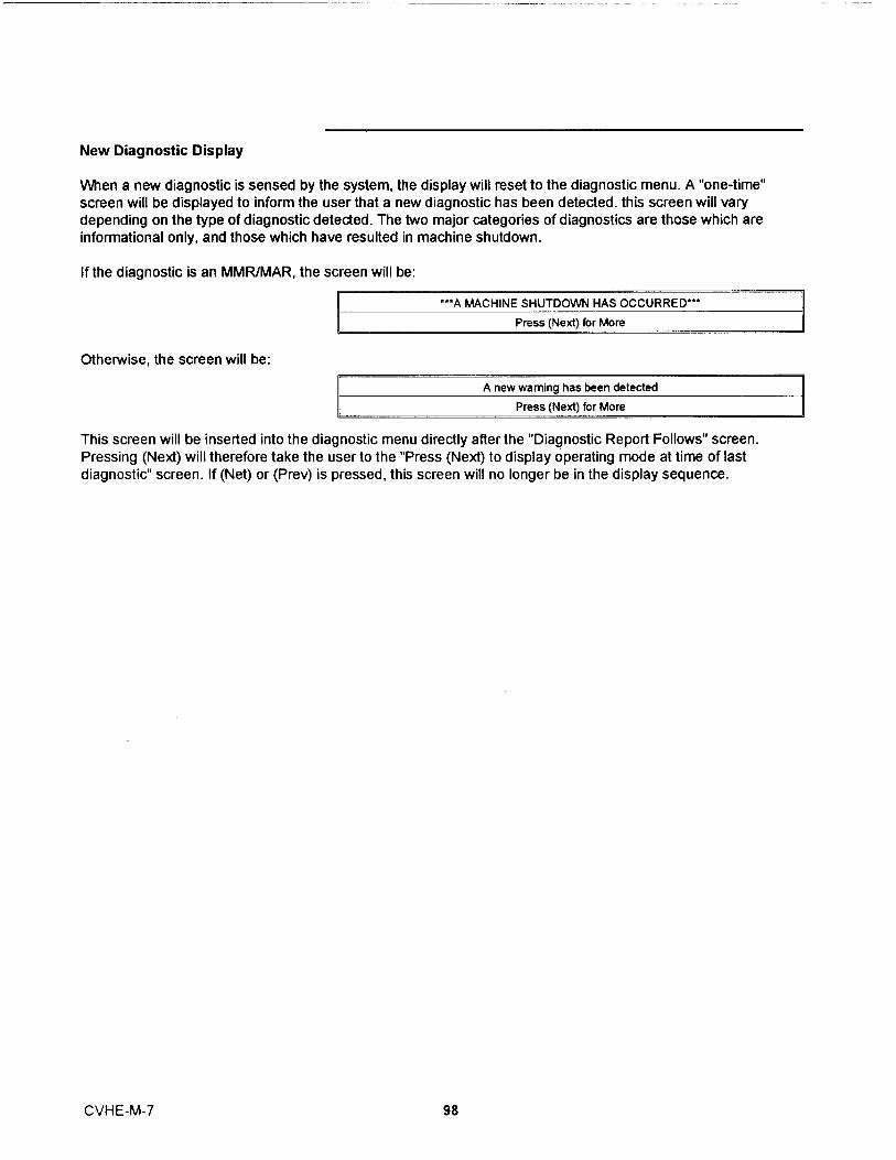
New Diagnostic Display
When a new diagnostic is sensed by the system , the display wi ll reset to the diagnostic menu . A "one-time"screen will be displayed to inform the user that a new d iagnostic has been detected . this screen will varydepending on the type of diagnostic detected . The two major categories of diagnostics are those which areinformational only , and those which have resulted in mach i ne shutdown .
If the diagnostic is an MMR/MAR, the screen will be:
***A MACHINE SHUTDOWN HAS OCCURRED"'
Press (Next) for More
Otherwise , the screen will be :
A new wamina has been detected
Press (Next) for More
This screen will be inserted into the diagnostic menu directly after the "Diagnostic Report Follows" screen.Pressing (Next) will therefore take the user to the "Press (Next) to display operating mode at time of lastdiagnostic" screen. If (Net) or (Prev) is pressed, this screen will no longer be in the display sequence.
CVHE-M-7 98

Diagnostic Codes
As shown below, a "LATCHING" diagnostic is a condition which shall cause the machine or a
portion of the machine _ as noted to shut down and shall require a manual reset to restore
operation . A diagnostic that is non-latching shall reset automatically when the condition
causing the diagnostic goes away . A non-latching diagnostic shall shut down the machine or
a part of the machine if so indicated . If a diagnostic is informative only, no machine orcircuit action is taken except to load a diagnostic code into the last diagnostic register .
Unless otherwise stated , all active diagnostics will be lost on loss of power.DIAGNOSTIC TYPES AND ACTION :
MMR = MACHINE SHUTDOWN - MANUAL RESETMAR = MACHINE SHUTDOWN - AUTO RESETCMR = CIRCUIT SHUTDOWN - MANUAL RESET Applies to Multible Rfgt Ci rcuit Units
Only - Defaults to an MMR on single C i rcuit Units .CAR = CIRCUIT SHUTDOWN - AUTO RESET Appl i es to Mult i ble Rfgt Circuit Units Only -
Defaults to an MAR on s i ngle Circu i t Un its .IFW = INFORMATION - WARNING May or may not affect machine operation ; lowest leve l
of diagnost i c .
REMOTELY RESETTABLE DIAGNOST ICS :
Except for the following , all diagnostics can be reset remotely from either the Remote Clear
Language Display , the Tracer, or the External Diagnostic Reset input at the Options Module .
The following diagnostics shall only be resettable ONLY at the Local Clear Language
Display , e . g . with the operator standing at the unit .
DIAGNOSTIC DESCRIPTION Appi Code Diag Can BeUnit Type RemotelyType Reset
Starter Contactor Interru pt Fai l u re All CA MMR No
Phase Loss All E4 MMR No
Phase Reversal All ES MMR No
Hig h Bearing #1 Ternp CTV EA MMR No
Hi h Bearin #2 Ternp CTV Eb MMR No
Current Overload A l l EC MMR No
Starter did not Transition CN FO MMR No
High Pressure Cutout Tripped All F5 MMR No
Low Eva p Rf t Tem . All Fb MMR No
Emer enc Stop In put All Fd MMR No
Starter Dry Run Test All 188 MMR No
Solid State Starter Fault Rly Clsd CTV 189 MMR No
High Motor Temp Position #1 CTV 18b MMR No
High Motor Temp Position #2 CTV 18C MMR No
High Motor Temp Position #3 CTV 18d MMR No
Severe Phase Unbal a nce All 1b2 MMR No
Starter Fault T e 1 CTV 1 E 9 MMR No
Starter Fault Type 11 CTV lEd MMR No
Sta rter Fault Type III CTV IFI M M R No
Cprsr did not Accelerate Fully CN 1F5 MMR No
The following are samples of applicable diagnostics .
99 CVHE-M-'

DIAGNOSTIC DESCRIPTION Diag Diag. Active CAUSE Help MessageType Modes
(Non-Active
Modes)
Aux/Ht Rcvry Ent Water Temp IFW All Open or shorted and Heat Recovery is installed Check Sensor , Wiring ,Sensor (at the CLD ) . and Connect ionsAux/Ht Rcvry Lvg Water Temp IFW All Open or shorted and Heat Recovery is installed Check Sensor , Wiring ,Sensor (at the CLD . and ConnectionsBearing Temp Sensor #1 MMR All Open or Short , only if this option is enabled at the Check Sensor , Wiring And
Human I nterface . ConnectionsBearing Temp Sensor #2 MMR All Open or Short , only i f this option is enabled at the Check Sensor , Wiring And
Human I nterface . ConnectionsCheck Clock IFW All On loss of power the clock does not keep time , if
there is an extended power loss (greater than 15 Check Mai n Power Supply ,seconds) th i s d iag . is also generated to alert the Reset Clockoperator to check the clock .
Ch i lled Water Flow Lost MAR All modes except a . The ch i lled water flow switch input was open Check Pump , Valves , FlowSTOP (00) and for more than 6-10 contiguous seconds . SwitchEXTERNAL b . 6- 10 seconds of contiguous flow shall clearSTOP (100) this d ia nostic .
Ch i ller Mod Ref Voltage IFW All An improper reference voltage was detected atCal i bration the Chi l ler Module . A 2 . 5 vdc reference is used Check Chil ler Module
to ca li b rate the non-ratiometric ana log I/O such Voltagesas 2- 10vdc and 420ma inputs as well as PWMAna log outputs . The micro checks to see thatthe A/D va l ue fal i s within an acoe table ran e .
Ch il ler : Loss of Comm with TCI IFW All The Tracer was setup as " installed " at the CLD Check IPCand the ch i ller module lost communica itons with W i r ing/Connect ionsthe TC I (comm 3 or comm 4) module for 15conti uous seconds
Chiller : Loss of Comm with Circu it MMR All The chil ler module lost communicat ions with the Check IPCCircuit module for 15 contiguous seconds . Wiring/Connect ions
Chil l er : Loss of Comm with Local IFW-AR All The chil le r module lost communicat ions with the Check IPCCLD LCLD module for 15 contiguous seconds . Wiring/Connect ionsNote : As implemented this is alatch i ng IFW diagnostic . That is ,once generated it cannot be re-generated until a manual reset isdone .
Chil l er : Loss of Comm with IFW All The chil ler modu le lost communicat ions with the Check IPCOptions Opt i ons modu l e fo r 15 cont i guous seconds . Th is Wiring/Connections
IFW diagnostic is generated if F ree Cooling i sNot Insta l led , otherwi se th is is an MMR diag .
under code 2F6Ch i ller : Loss of Comm with MMR All The chiller modu le lost communicat ions with the Check IPCOptions Opt i ons modu le fo r 15 cont i guous seconds . This Wiring/Connections
MMR diagnostic is generated if Free Cooling isIn sta lled , otherwise thi s i s an IFW diag . undercode 2AE
Ch i ller : Loss of Comm with Purge IFW All The chil ler modu le lost communicat ions with the Check IPC
Purge module for 1 5 contiguous seconds . Wiring/ConnectionsCh i ller : Loss of Comm with Starter MMR All The chiller module lost communicat ions with the Check IPC
Starter module for 15 cont iguous seconds . Wirin /ConnectionsCh i l l er : Loss of Comm with MMR All The chille r modu le lost communicat ions with the Check IPCStepper #1 Ste er #1 modu l e fo r 15 cont i g uous seconds . Wirin /ConnectionsCh Ir Sat Cond Temp Senso r IFW All Open or Shorted Sensor Purge Inop : See Purge 0( Purge) a . Appl ies to Retrofit app li cat i ons of the Purge & M Manual(As Sensed by the Purge module On l y . Does not apply to UCP2 app l icat ions .in Retrofi t a lica itons b . IFW to the ch i ller , MMR to the Purge .Ci rc u it Mod Ref Voltage IFW All An imp roper reference vo ltage was detected at See TroubleshootingCa l ibrat i on the C i rcuit Module . A 2 . 5 vdc reference is used Service Bulletin
to ca li b rate the non-rat i ometric analog I/O suchas 2- 10vdc and 420ma inputs as well as PWMAnalog outputs . The m ic ro checks to see thatth e AID va lu e fa ll s within a n acceptable range .
Circ u it Modu le 24 Vdc Ref IFW Al l 24vdc reference missing and the Rfgt monitor i s Check Rfgt MonitorMissi ng insta lled . Wi rin g/24 Vdc Supply .
100CVHE-M-7

DIAGNOSTIC DESCRIPTION Diag Diag . Act ive CAUSE Help MessageType Modes
(Non-ActiveModes)
Circuit : Loss of Comm with Chiller MMR All The c i rcuit module lost communications with the Check IPCChiller module for 15 contiguous seconds . Wiring/ConnectionsOn loss of communications , the circuit modulesha l l run the oil pump for the post lube t ime andthen turn the oil pump off . On loss ofcommun ications , the circuit module shal lcontinue to control the oil heater.
Ci rcuit : Loss of Comm with Starter MMR All The circuit module lost communications with the Check IPCStarter module for 15 contiguous seconds . W i r i n g/Connections
Cond Diff Water Press IFW A l l Input Shorted or Open and the D i fl . water Check Sensor , Wiring ,Transducer pressure sensing option , > 150 psig , is " installed " and Connections
at the CLD .Cond Enteri ng Wtr Temp Sensor IFW A l l Open or Short Check Sensor , Wiring And
ConnectionsCond Leaving Wtr Temp Sensor IFW All Open or Short . Check Sensor , Wiring And
a . IFW on Chilled Water Control Connectionsb . MMR on Heat Pump Hot Water Control .
Condenser Rfgt Pressure Sensor MMR All Open or Short . Check Sensor , Wiring AndMust Hold on open AND short i nput is 2 . 0 Psia . ConnectionsDesign : Both opens and shorts resuR in thepressure going to the low end of the scale .Therefore a Must Hold on the h igh pressure endis not req uired .
Condenser Rfgt Temp Sensor MMR All Open or Short Check Sensor , Wiring AndConnect i ons
Condenser Water Flow Lost MAR Start and Al l Run The condenser water flow switch i nput was open Check Pumps , Valves ,Modes . for more than 6-10 contiguous seconds . Flow Switch
Condenser Water Flow Overdue MMR Estab . Cond Condenser water flow was not proven within 3 Check Pump , Valves , FlowWater Flow minutes of the condense r pump re l ay being Switch
energized .Condense r Water Pressure MMR Al l Open or Short and the Cond Water Pressure Check Sensor , W i r i ng ,Sensor Sensor is setup as instal led at the Clear and Connect i ons
Lan ua e Dis la .Cprsr did not Accelerate Fully MMR Start ing a . Us i ng e ither a Solid State Starter or a Variable Check End of Limt/At
Speed Drive the UCM did not receive an Up to Speed InputSpeed or At Speed Signal within the MaximumAcce leration Timer Setting .b . The Up to Speed/At Speed input was found tobe shorted before the compressor was started .c . App l ies only to Solid State Starters andVariabfe S eed Drives .
Cprsr did not Acce lerate : MMR Start Mode a . The compressor did not come up to speed in Check Main Power Supp lyShutdown the allotted time defined by the Maximum & Wiri ng
Acceleration Timer .b . The Human Inte rface setups defi ned"Shutdown" as the act i on when the MaximumAcceleration Timer was exceeded .
Cprsr Did Not Accelerate : IFW Sta rt Mode a . The compressor did not come up to speed in See Troub l eshootingTransition the al l otted time defined by the Maximum Service Bul l et in(The Motor is put across the line . ) Accelerat i on Timer .
b . The Human Interface setups defined"Transition" as the act i on when the MaximumAcceleration T imer was exceeded .
Current Overload MMR Al l Running Motor current exceeded overload t i me vs tripModes characteristic . Check Main Power Supply
& WiringCurrent Overload Setpts Error I FW All a . The redundant overload sett i ngs d i d not agree Review Overload Set Up
for 30 cont iguous seconds . (Cont i nue to use theprevious value for the 30 second timeout . ) Whenthis diagnostic occurs the affected StarterModule shal l use the minimum (00000 binary , 00decimal) overload sett i ng as a default unti l e i therthe UCM is reset or , if the redundant settingsagree aga i n , the starter modu l e can go back tousing the actual setting .
101 CVHE-M-7
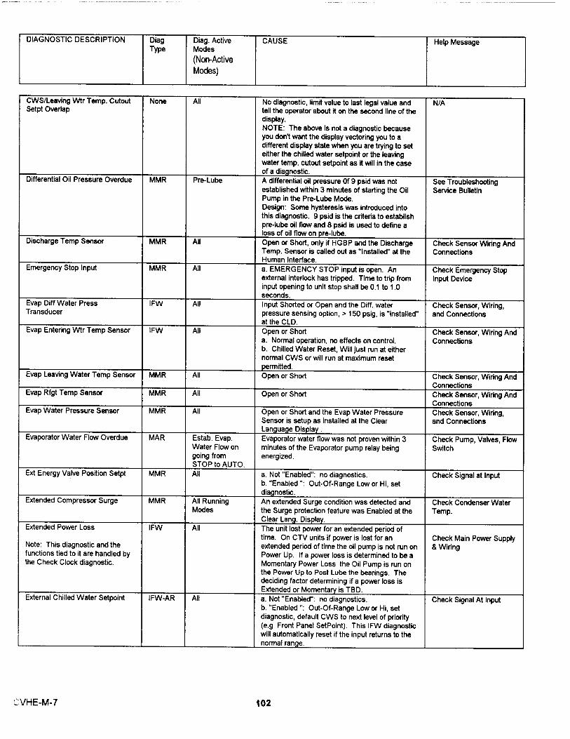
D IAGNOSTIC DESCRIPTION Diag Diag . Active CAUSE He lp MessageType Modes
(Non-Active
Modes)
CWS/Leaving Wtr Temp . Cutout None All No diagnostic , limit value to last legal va l ue and N/ASetpt Overlap tell the operator about it on the second l ine of the
display .NOTE : The above is not a diagnostic becauseyou don 't want the display vectoring you to adifferent display state when you are trying to seteither the chilled water setpo int or the leavingwater temp . cutout setpoint as it will in the caseof a dia nost ic .
Differential Oil Pressure Overdue MMR Pre-Lube A differential oil pressure Of 9 ps i d was not See Troubleshootingestablished with i n 3 minutes of start i ng the Oil Service BulletinPump in the Pre-Lube Mode .Design : Some hysteresis was introduced intothis d iagnostic . 9 psid is the criteria to establ ishpre-lube oil flow and 8 psid is used to define aloss of oil flow on pre-lube .
Discharge Temp Sensor MMR All Open or Short , only i f HGBP and the Discharge Check Sensor Wiring AndTemp . Sensor is cal l ed out as " Installed" at the ConnectionsHuman Interface .
Emergency Stop Input MMR Al l a . EMERGENCY STOP input is open . An Check Emergency Stopexternal interlock has tri pped . Time to t rip from Input Dev iceinput opening to un it stop shaH be 0 . 1 to 1 . 0seconds .
Evap Diff Water Press IFW All Input Shorted or Open and the Diff . water Check Sensor , Wiring ,Transducer pressure sensing option , > 150 psig , is " instal l ed" and Connections
at the CLD .Evap Entering Wtr Temp Sensor IFW All Open or Short Check Sensor , Wiring And
a . Normal operat i on , no effects on control . Connectionsb . Chilled Water Reset , Wi l l just run at eithernormal CWS or wil l run at maximum resetpermitted .
Evap Leaving Water Temp Sensor MMR All Open or Short Check Sensor , Wiring AndConnect ions
Evap Rfgt Temp Sensor MMR All Open or Short Check Sensor , Wiring AndConnect ions
Evap Water Pressure Sensor MMR All Open or Short and the Evap Water Pressure Check Sensor , Wiring ,Sensor is setup as insta l led at the Clear and ConnectionsLan ua e D is p lay .
Evaporator Water Flow Overdue MAR Estab . Evap . Evaporator water flow was not proven within 3 Check Pump , Valves , FlowWater Flow on minutes of the Evapo rato r pump re lay being Switchgoing from energ ized .STOP to AUTO .
Ext Ene rgy Valve Position Setpt MMR All a . Not " Enabled ": no diagnostics . Check Signal at Inputb . " Enab l ed ": Out-Of-Range Low or H i, setd i ag nostic .
Extended Compressor Surge MMR A l l Running An extended Su rge cond it ion was detected and Check Condenser WaterModes the Surge protection feature was Enabled at the Temp .
C l ear Lan . Dis la .Extended Power Loss IFW A l l The unit lost power for an extended pe riod of
t ime . On CTV units if power i s l ost for an Check Main Power SupplyNote : This d i agnostic and the extended per iod of t i me the oil pump i s not run on & Wiringfunctions t ied to it a re hand l ed by Powe r Up . I f a power loss is dete rm i ned to be athe Check Clock d i agnostic . Momentary Power Loss the Oi l Pump is run on
the Power Up to Post Lube the bearings . Thedeciding factor determining if a power loss isExtended or Momenta is TBD .
External Ch il led Water Setpoint I FW-AR Al l a . Not " Enabled": no diagnostics . Check Signal At Inputb . " Enabled ": Out-Of- Range Low or Hi , setdiagnostic , default CWS to next level of priority(e . g . Front Pane l SetPoint ). This I FW diagnosticwill automat i cal l y reset i f the input retu rns to thenorma l ran e .
(_`VHE -M- 7 102

DIAGNOSTIC DESCRIPTION Diag Diag. Active CAUSE Help MessageType Modes
(Non-Active
Modes)
External Current Limit Setpoint IFW-AR All a . Not "Enab led": no diagnost i cs . Check Signal At Inputb . " Enabled ": Out-Of-Range Low or Hi , setdiagnost ic , default CLS to next level of priority(e . g . Front Panel SetPo i nt . This IFW diagnosticwi ll automat ica lly reset if the input returns to thenorma l ra n e .
External Hot Water Setpoint I FW-AR All a . Not " Enabled": no diagnost ics . Check Signal At Inputb . " Enabled ": Out-Of-Range Low or Hi , setdiagnostic , default HWS to next level of priority(e . g . Front Panel SetPoint) . Th is IFW diagnosticwill automatica l ly reset if the input returns to thenormal ran e .
Externa l Vane Posit ion Setpoint MMR A l l a . Not " Enabled": no diagnostics . Check Signal at Inputb . "Enabled ": Out-Of-Range Low or Hi , setd i agnostic .
Free Cool ing Valves MMR When exiting a . The Free Coo ling Valves were commanded to Check Clsd End-Free cooling close and did not close in the three minutes Switches , Va lves , Wiring
al l owed for closure . And FC is installed (at theCLD) and commanded off .b . The Free Cooling Valves were commanded toopen and did not open in the three minutesal l owed for closure . And FC is installed (at theCLD and commanded On .
Heat Sink Temp Sensor IFW All Open or Short and Solid State Starter installed . Check Sensor Wiring AndConnections
High Bearing #1 Temp MMR All starting and a . The bearing temperature at sensor #1 Check Oil Systemrunning modes exceeded 180 + or - 5 F (82 . 2 C ) for 0 . 5 - 2
seconds (Note : BT , WT , and DT may be"instantaneous tr i p" but consistent with theana log input fil te ri ng function .), andb . Th is funct i on i s enabled at the HumanInterface .
High Bearing #2 Temp MMR All starting and a . The bearing tempe rature at sensor #2 Check Oil Systemrunning modes exceeded 180 + or - 5 F (82 . 2 C ) for 0 . 5 - 2
seconds (Note : B T, WT , and DT may be" instantaneous tr i p " but consistent with theanalog input filter i ng function . ) , andb . This funct i on is enabled at the HumanI nte rface .
H i gh Cprsr Discharge Temp . MAR Al l a . The d ischa rge temp . exceeded the t rip va l ue ; See Troubl eshoot i ng200 F + or - 5 F for CVHE/F . CVG and CVA . Service Bul l et i nThe Discharge Temp Cutout is adjustable at theHuman Interface .b . Time to trip from trip value exceeded sha l l be0 . 5 to 2 . 0 seconds . ( Note : BT , WT , and DT maybe "instantaneous trip " but consistent with theanalog input filtering function . )d . The d i ag . shall reset automatically 50 F belowthe t r i oi nt .
H igh Motor Temp Position #1 MMR Any Start and The Motor wind i ng temp . at sensor #1 exceeded See Troubleshoot i ngRun Mode 265 F + or - 15 F for 0 . 5 - 2 seconds . ( Note : BT , Serv ice Bulletin
WT , and DT may be "instantaneous t rip " butconsistent with the analog i nput fiRe ring function . )
H i gh Motor Temp Position #2 MMR Any Start and The Motor Winding Temp . at sensor #2 See Troubleshoot ingRun Mode exceeded 265 F + or - 15 F for 0 . 5 - 2 seconds . Service Bu l letin
(Note : BT , WT , and DT may be "instantaneoustrip" but consistant with the ana log input fi lter i ngfunction . )
H i gh Motor Temp Position #3 MMR Any Start and The Motor Winding Temp . at sensor #3 See Troubleshoot i ngRun Mode exceeded 265 F + or - 15 F for 0 . 5 - 2 seconds . Service Bu lletin
(Note : BT , WT , and DT may be "i nstantaneoust ri p" but consistent wit h the an a log in put filteringfunction .
103 CVHE-M- 7

D IAGNOSTI C DESCRIPTION D i ag D i ag . Active CAUSE Help MessageType Modes
(Non-Active
Modes)
H igh Oi l Temp MMR A l l starting and UCP2 sha l l provi de a fixed H i gh O i l Temperature Check Oil System
running Modes Cutout of 180 F (82.2 C ). If the oi l temperature
violates the cutout by 120 degree F seconds
(66 . 6 degree C seconds) an MMR diagnostic
shall be generated .
H i gh Pressure Cutout Tripped MMR All A h igh pressure cutout was detected . See the Check Condenser Water
trip points for the various products under the Temp .
H PC switch description of th is specificat ion .
High Restart Inhibit T imer IFW All The Restart Inh i bit timer has reached a maximum Check for Excessive
Warning threshold for the host chiller . For CTV chil le rs Chil l er Cycling
this is 45 minutes . This indicates excess ive
ch ille r cycling , steps should be taken to correct
th is .
H igh Vacuum Lockout MMR Pre-Start The Oil Tank Pressure t ransducer shall be used See T roubleshoot ing
to sense for very low pressures in all Non- Service Bu lletin
running cprsr modes .
I GV BPI Found Low During IFW Al l The I nlet Guide Vane Actuator Binary Posit i on Check Stepper Module ,
Search Ind i cator was found too low in the stroke of the Wi ring , & Motor
IGV during the BPI search .
IGV BPI Not Found Dur i ng IFW Al l The I n let Guide Vane Actuator Binary Posit i on See Troubleshooting
Sea rch Ind i cator was not found over the ent i re stroke of Service Bulletin
the I GV during the BPI search .
IGV BPI Shorted IFW Pre-Start At what is bel ieved to be a c l osed posit i on , the Check Sensor , Wiring ,
IGV BP I was found to be shorted . and Connections
I GV Electrica l Drive C ircuit Open MMR On Demand and Run the I GV Acturator e l ectrica l dr ive circuit test See Troubleshoot ing
(Ava i lable CTV Phase ?? release ) P re- Start both on demand from the human interface and Service Bu l letin
just before the chil l e r starts .
I nco rrect Chi ll er Softwa re Inst al l ed MMR A ll The i ncorrect Eprom was loaded into this ( No message is requ i red .)
modu l e . Th i s d i agnostic is detected when a
factory test computer sets the un i t type to
something other than what the Eprom software
was intended fo r.
I ncor rect Stepper Software MMR All The incorrect Eprom was l oaded into this ( No message is required .)
Insta l led module . Th is d iagnostic is detected when a
factory test computer sets the unit type to
something other than what the Eprom software
was intended for .
Low Chi l led Water Temp : Unit Off I FW-AR Unit in Auto and a . The chi l led water temp . fel l be l ow the cutout Check Flow , Sensor , &
No CkPs Energzd setpoi nt wh ile the compressor (or Solut ion Pump) Wiring
( Un it in Auto but not Starting or (Any was not running for 30 degree F Seconds .
Running) Ckt(s ) Energzd) Automatic Reset of the IFW d iag shall occur 2
de rees F 1 . 1 C above the cutout set int .
Low Ch i lled Water Temp : Unit On MAR Any Ckt (s) a . The ch i lled water temp . fell below t he cutout Check F low , Sensor , &
Energzd setpo i nt wh i le the compressor (or Solution Pump) W i r i ng
( Unit Starting or Runn ing) ( No CkYs was runn i ng for 30 degree F Seconds .
Energzd) Automatic Reset of the MAR diag sha l l occur 2
de rees F 1 . 1 C above the cutout set oint .
Low D i fferent i a l O i l Pressure MMR A l l sta rting and Pre-Lube Mode on CVHE/F Chil lers : Check Oil System
running Modes a . See Diagnostic : Differential o i l pressure
overdue .
Start & Run Mode on CVHE/F Chi l lers :
a . If dur i ng these modes the D i fferenti al oil
pressu re drops be low 9 PS I D for more than 90
Psid Seconds , an MMR diagnostic shall be
generated . The 90 Psid Seconds integ ral sha l l
be reset to zero when the different ia l pressu re
rises above 9 ps id .
Low Evap Rfgt Temp . MMR Sta rter Contactor a . The Satu rated Evap Rfgt Temp dropped be low
Ene rgized the Low Rfgt Temp . Cutout Setpo i nt when the Check Operation , Call
circuit was runn i n g for 30 deg ree F seconds . Service
Low Evap . Water Flow IFW Al l Runn i ng a . The evap . water flow measurement opt i on was See Troubleshooting
(To be implemented in CTV Modes i nstal l ed and the flow dropped to a setpoint set at Service Bulletin
Phase C re lease and ABS Phase the CLD .
B re l ease .
104
CVHE-M-7

D IAGNOST I C DESCRIPTION Diag Diag . Active CAUSE Help MessageType Modes
(Non-ActiveModes)
Low Evap . Water Flow IFW Al l Running a . The evap . water flow measurement option was See Troub l eshooting(To be implemented in CTV Modes insta lled and the flow dropped to a setpo i nt set at Service Bul letinPhase C re l ease and ABS Phase the CLD .B re l ease .
Low Oil Temp MAR All Non-runn i ng The oi l temperature dropped below its adjustable See TroubleshootingModes . Low Oil Temp . Cutout . ("I nstantaneous trip" but Service Bulletin
cons istant with the analog input fifter ing funct ion .)Automatic Reset of the MAR diag sha l l occur 5de rees F 2 . 8 C above the cutout set int .
Max Acceleration Setpts IFW All a . The redundant Maximum Acceleration settings Review Max AccelerationError did not agree for 30 contiguous seconds . Set Up
(Continue to use the prev ious value for the 30second timeout . ) When this diagnost ic occursthe affected Starter Module shal l use 6 secondsas a default unti l e ither the UCM is reset or , if theredundant sett i ngs agree again , the startermodule can o back to usin the actual sett i n .
Max Pumpout Rate Exceeded IFW Al l a . IFW to the ch i ller , MAR to the Purge . Purge Inop : See Purge 0(P rg) & M ManualMax Pumpout Rate Exceeded-Svc I FW Al l a . IFW to the ch il ler , MAR to the Purge . Purge Inop : See Pu rge 0( P rg) & M ManualMemory Error Type I : NOVRAM MMR On UCM Power a . On UCM either power up or fo l lowi ng a Type I I
Up or following a Memory Error a NOVRAM memory error was Cal l Serv i ce to Check a l lType II Memory detected . The UCM is operat i ng on all Sett ingserror diag . Engineer i ng ROM defaults for al l setup
pa rameters . Check a l l setup parameters andcontinue to run ch ill e r. Replace the Chi ll erModule as soon as a replacement is avai l ab l e .Note : It is expected that this diagnost ic wi l l bedetected on the very first power up of the Chi l lerModule at the Manufacturer since the NOVRAMwi l l not conta i n va l id data on fi rst wer u .
Memory Error Type II: Shadow IFW All a . A Shadow RAM memory erro r was detected . No Sett i ngs Were LostRAM The UCM is operat i ng on al l last val i d va l ues
(pul l ed from NOVRAM) for al l setup parameters .No setup parameter changes were pending to beloaded into NOVRAM , a complete recovery of al lsetup parameters was made and the re is no needto check un it setup pa rameters . Compressorsta rts and hour were lost for not more than thelast 24 hours . Th is is expected to be an isolatedevent and repair or rep l acement i s not required .I f this diagnost i c does occur repeated ly , thenre lace the Chiller module .
Memory Error Type III IFW Al l a . A Shadow Ram memory error was detected . Sett i ngs Changed i n TheThe UCM is operating on all last valid values Last 24 Hours Lost( pu lled from NOVRAM) for a l l setup parameters .Setup parameter changes less than 24 hours oldpend i ng to be loaded into NOVRAM were lost .Check all setup pa rameters made in the last 24hours . Compressor starts and hours were lostfor not more than the last 24 hou rs . This isexpected to be an isolated event and repa i r orreplacement is not requ i red . If th is diagnosticdoes occur repeatedly , then rep lace the Chil lermod ule .
Momentary Power Loss MAR A l l Running Determine Cause OfModes Power Inte rruption( Start Mode , e . g .Before
Trans it i on )MOTOR TEMP SENSOR #1 MMR A l l Open or Short Check Sensor , W i r i ng And
ConnectionsMOTOR TEMP SENSOR #2 MMR A l l Open or Short Check Sensor , W i ring And
Connect ionsMOTOR TEMP SENSOR #3 MMR All Open or Short Check Sensor , Wiring And
Connect ions
105
CVHE-M-7
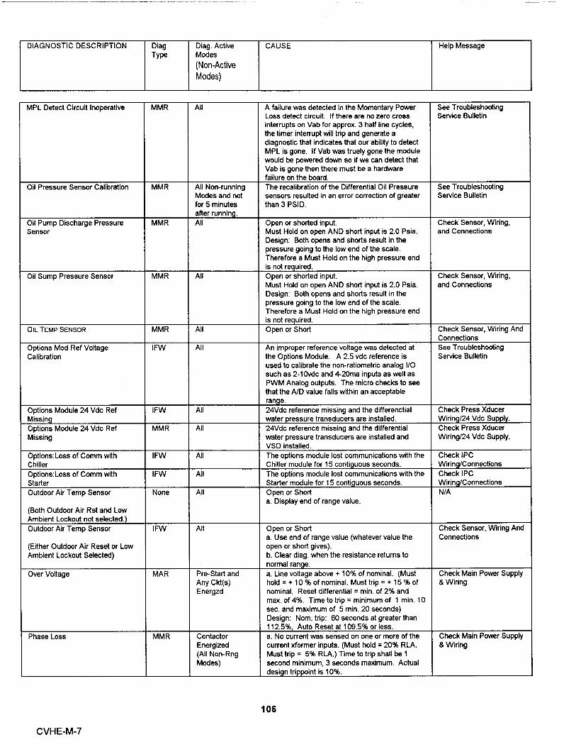
D IAGNOST I C DESCRIPTION D i ag Diag . Active CAUSE He l p MessageType Modes
(Non-Active
Modes)
MPL Detect Circu it Inoperative MMR A l l A fa il ure was detected i n the Momentary Power See Troubleshooting
Loss detect circuit . I f there are no zero cross Service Bulletin
inter rupts on Vab for app rox . 3 half l ine cycles ,
the t ime r interrupt will trip and generate a
diagnostic that indicates that our abil ity to detect
MPL is gone . If Vab was truely gone the module
wou l d be powered down so if we can detect that
Vab is gone then the re must be a hardware
fai l ure on the boa rd .
O i l Pressure Sensor Calibrat i on MMR All Non-runn i ng The reca l ibrat ion of the Differential Oil Pressure See Troub leshooting
Modes and not sensors resulted in an error correcti on of g reater Service Bul l et i n
for 5 minutes than 3 PSID .
after runn in .
O i l Pump Discharge Pressu re MMR All Open or shorted i nput . Check Sensor , Wiring ,
Sensor Must Ho ld on open AND short input is 2 . 0 Psia . and Connect ions
Design : Both opens and shorts result i n the
pressure going to the l ow end of the scale .
Therefore a Must Ho l d on the high pressure end
i s not re u i red .
Oil Sump Pressure Sensor MMR Al l Open or shorted i nput . Check Sensor , W ir i ng ,
Must H old on open AND short i nput is 2 . 0 Psia . and Connect ions
Design : Both opens and shorts resu lt in the
pressure going to the low end of the sca le .
Therefo re a Must Hold on the h i g h pressu re end
is not re u i red .
O IL TEMP SENSOR MMR A l l Open or Short Check Sensor , Wi ring And
Connections
Opt ions Mod Ref Vo ltage I FW A l l An improper reference voltage was detected at See Troubleshooting
Cal i brat ion the Opt ions Module . A 2 . 5 vdc reference i s Service Bulletin
used to ca li brate the non-ratiometric analog I /O
such as 2-10vdc and 420ma inputs as we l l as
PWM Ana log outputs . The m i cro checks to see
that the A/D value fal l s with i n an acceptable
range .
Opt ions Module 24 Vdc Ref I FW All 24Vdc refe rence miss i ng and the d i fferenct i al Check Press Xducer
Miss i n g water pressu re transducers are i nsta ll ed . Wiring/24 Vdc Supp ly .
Options Module 24 Vdc Ref MMR All 24Vdc referen ce m issing and the d i fferent i a l Check Press Xducer
Missing water pressure transducers are i nstal l ed and Wi ring/24 Vdc Supply .
VSD insta lled .
Options : Loss of Comm with IFW Al l The options modu l e l ost communicat ions wit h t he Check IPC
Ch il ler Ch i l l er modu le for 15 contiguous seconds . Wiring/Connections
Options : Loss of Comm with IFW Al l The options module lost communications wit h the Check IPC
Starte r Starter modu le for 15 cont i guous seconds . W i r i n g/Connect i ons
Outdoor Ai r Temp Sensor None A l l Open o r Short N /A
a . D i splay end of range va l ue .
( Both Outdoor Air Rst and Low
Amb i ent Lockout not selected . )
Outdoor Air Temp Sensor IFW A l l Open or Short Check Sensor , Wiring And
a . Use end of range value (whateve r value the Connections
(E ither Outdoor Ai r Reset or Low open or short g ives).
Ambient Lockout Selected) b . Clea r diag . when the res i stance retu rns to
normal ran e.
Over Vo ltage MAR Pre-Start and a . Line voltage above + 10% of nom i na l. ( Must Check Ma i n Power Supply
Any Ckt (s ) hold = + 10 % of nom i na l. Must tri p = + 15 % of & Wiring
Ene rgzd nominal . Reset d i ffe rential = min . of 2% and
max . of 4%. T ime to tr i p = m inimum of 1 min . 10
sec . and max imum of 5 min . 20 seconds)
Des ign : Nom . t ri p : 60 seconds at g reater than
112 . 5%, Auto Reset at 109 .5% or less .
Phase Loss MMR Contactor a . No current was sensed on one or more of the Check Main Power Supply
Energ ized current xformer inputs . (Must hold = 20% RLA . & Wiring
(All Non- Rng Must trip = 5% RLA .) Time to tri p shal l be I
Modes) second min imum , 3 seconds maximum . Actual
desi n tri i nt is 10 96.
106
CVHE-M-7

DIAGNOSTIC DESCRIPTION Diag Diag . Act ive CAUSE Help MessageType Modes
(Non-Active
Modes)
Phase Reversal MMR Contactor a . A phase reversal was detected on theenergized to incoming current . On a compressor startup the Check Main Power Supplytrans it ion phase reversa l log ic must detect and tr i p in a & Wiri ngcommand (A l l maximum of 0 . 7 second from compressor startOther Times) for CTV .
Phase Reversal P rotection Lost MMR Starter Contactor a . The phase reversa l protect i on on the Check Starter Module .energized to compressor has become inoperat ive . The phasetransition rotat i on protection system failed to detect 2 in acommand row of one of the four phase c ircuit states ; Phase
reve rsal , Phase rotation OK, Phase A lost , PhaseB lost .
Purge Cprsr Suction Temp IFW All Open or Shorted Sensor Purge Inop : See Purge 0Sensor a . IFW to the chi l ler , MMR to the Purge . & M Manual
Purge Liquid Level Too High IFW All a . The Level Switch at the purge opened for 6 to Purge Inop : See Purge 010 Seconds . & M Manualb . IFW to the ch i ller , MMR to the Pur e .
Purge Memory Error III IFW A l l a . A Shadow Ram memory error was detected . No Settings Lost
Compressor starts and hours were lost for notTh is d i ag wi l l be seen in UCP2 more than the last 24 hours . Th i s is expected toappl ications of the Purge Module . be an isolated event and repair or replacement isThis diag will not be seen in not required . If this d iagnostic does occurretrofit applications of the Pu rge repeated ly , then rep l ace the Purge module . Th isModu l e . is an IFW d i agnost ic to both the Purge and
Chill e r.
Purge Memory Error Type I : MMR On Purge Power a . On either Purge Module power up or following Purge I nop : See Purge 0NOVRAM Up or following a a Type I I Memory E rro r, a NOVRAM memory & M Manual
Type II Memory error was detected . The Purge Module isThis diag . should be seen i n both error diag . operating on al l Engineer ing ROM defaults for allUCP2 and retrofit appl ications setup parameters . Check al l setup parametersonly . and continue to run purge . Replace the Purge
Module as soon as a replacement is available .Note : It i s expected that this diagnostic wil l bedetected on the very first power up of the PurgeModule at the Manufacturer since the NOVRAMwil l not conta i n va l id data on fi rst wer up .
Pu rge Memory Error Type II : IFW Al l a . A Shadow RAM memory erro r was detected . No Sett i ng Were Lost
Shadow RAM The Purge Mod ule is ope ra ting on a ll l ast va li d
va l ues (pu lled from NOVRAM) for a l l setupThis d iag . shou l d be seen in parameters . No setu p pa rameter changes wereret rofit appl i cations on ly . pend ing to be loaded into NOVRAM , a comp l ete
recovery of all setup parameters was made and
there is no need to check un it setup paramete rs .
Compressor starts and hour were l ost for notmore than the last 24 hours . Th i s i s expected tobe an iso l ated event and repair or replacement is
not requ i red . I f th i s d i agnostic does occur
re eatedl , then re lace the Pur e module .
Purge Memory E rro r Type III IFW A l l a . A Shadow Ram memory error was detected . Settings Changed in The
The Purge Module is operating on all last val i d Last 24 Hours LostThis diag . should be seen in va l ues (pulled from NOVRAM) for al l setupretrofit applications only . parameters . Setup pa rameter changes less than
24 hou rs o l d pend i ng to be loaded i nto NOVRAM
were lost . Check a ll setup pa rameters made inthe last 24 hours . Compressor starts and hours
we re lost for not more than the last 24 hou rs .
T h is is expected to be an isolated event and
repai r or rep lacement is not requ i red . If this
diagnost i c does occu r repeated ly , then replace
the Pur e module .
Purge : Loss of Comm w/ Retrofit I FW Al l The purge module lost communicat i ons with the Check IPCCLD retrofit Human I nterface modu l e fo r 15 Wiri ng/Connections
cont i uous seconds .
Pu rge : Loss of Comm with Ch i ller I FW Al l T he purge mod ul e lost commu nicat i ons wit h the Check IPC
c h il ler mod ule for 15 cont iguous seconds . Wiring/Connect ions
a . IFW to the ch ill e r, MAR to the Pu r e .
107
CVHE-M-7

DIAGNOSTIC DESCR I PTIO N D iag Diag . Active CAUSE He l p MessageType Modes
(Non-Active
Modes)
Purge Memory Error Type I I I IFW All a . A Shadow Ram memory error was detected . Sett i ngs Changed in The
The Purge Module is operating on all last valid Last 24 Hours Lost
This diag . should be seen in va lues (pulled from NOVRAM) for all setup
retrofit applications only . parameters . Setup parameter changes less than
24 hours o l d pending to be loaded i nto NOVRAM
were lost . Check all setup parameters made in
the last 24 hours . Compressor starts and hours
we re lost for not more than the last 24 hours .
This is expected to be an isolated event and
repair or replacement is not required . If this
diagnost i c does occur repeatedly , then replace
the Pur e module .
Purge : Loss of Comm w/ Retrofit IFW A l l The purge module lost communicat i ons with the Check IPC
CLD retrofit Human I nterface modu le for 15 W i r i ng/Connect ions
conti uous seconds .
Pu rge : Loss of Comm with Chil l e r IFW All The purge module lost communications with the Check IPC
chiller module for 15 contiguous seconds . Wiring/Connect ions
a . IFW to the chiller , MAR to the Pur e .
Purge : Loss of Comm with Opt ions IFW All The purge modu le lost commun ications with the Check IPC
ch i ller module for 15 cont i guous seconds . Wiring /Connections
a . IFW to the chiller , IFW to the Pur e .
Purge : Loss of Comm with Starte r IFW All The pu rge module lost communications with the Check IPC
starte r module for 15 cont iguous seconds . Wiring/Connections
a . IFW to the chiller , MAR to the Pur e .
Purge : Loss of Comm with Stepper IFW Al l The pu rge modu l e lost commun i cations with the Check IPC
circu it module for 15 cont iguous seconds . Wiring/ Connections
a . IFW to the ch il ler , MAR to the Pur e .
Purge : Loss of Comm with Stepper IFW All The purge module lost communications with the Check IPC
#1 chiller module for 15 contiguous seconds . Wiring/Connections
a . IFW to the chiller . MAR to the Pur e .
Purge : Loss of Comm with Steppe r IFW All The purge modu le lost communicat ions with the Check IPC
#2 chiller module for 15 contiguous seconds . Wiring/Connections
a . IFW to the chiller , MAR to the Pur e .
Refrigerant Monitor Sensor IFW All Open or Shorted i nput and the Rfgt Monitor is Check Sensor , Wiring ,
setup as installed at the Clear Lan ua e Dis la . and Connections
Severe Phase Unba lance MMR All Runn i ng a . A 25% Phase Unba lance d i agnostic has been Check Main Power Supp ly
Modes detected . Items to check are the Current & Wiring
Transformer Part Numbers (they should all
match), The Cu rrent Transformer res i stances ,
line voltage phase balance , a ll power wiring
connections , the contactor pole faces , and the
motor. I f al l these are OK, replace the Starte r
module .
Sol id State Starte r Fault Rly C l sd MMR Any Start and The SSS fault re l ay C l osed . See Solid State Sta rter
Run Mode Service Bulletin
Starter Contactor Interrupt Failure MMR Starte r Contact a . Welded Starter contactor . Complete Starter
not Energ ized b . Detected a welded compressor contactor when Checkout Required
(Starter Contact the compressor was commanded off but the
Energized) current did not go to zero . Detection time shall
be 5 second m i n imum and 10 seconds maximum
for all Electromechanical and Solid State
Starters . Detection time for Variable Speed
Drives sha l l be 12 seconds min imum and 17
seconds maximum . On detection , generate the
diagnostic , ene rgize the appropriate alarm relay ,
cont i nue to command the affected compressor
off..
108
CVHE-M-7

DIAGNOSTIC DESCRIPTION Diag Diag. Active CAUSE Help MessageType Modes
(Non-Active
Modes)
Starter did not Transition MMR On the first a . The UCM did not receive a transition comp lete Complete Startercheck after signal in the designated time from the UCM Checkout Requiredtrans ition . command to transition . The must hold time from
the UCM transition command is 1 second . TheMust trip time from the transition command is 6seconds . Actual design is 2 .5 seconds .b . The Transition Complete input was found to beshorted before the compressor was started .
c . Item a . above is act ive only for Y-DeRa , Auto-Transformer , and Primary Reactor Starters .
d . I tem b . above is active for allelectromechanical starters .
Starter Dry Run Test MMR Starter Dry Run While in the Starter Dry Run Mode either 50 % Current or VoltageMode Line Voltage was sensed at the Potential Detected
Transformers or 10 % RLA Current was sensed
• at the Current Transformers .
Starter Fault Type I MMR Starting a . This is a specific starter test where i M is See Troubleshoot i ng
closed first and a check is made to ensure that Service Bul l et i nthere are no currents detected by the CTs . Ifcurrents are detected when only 1 M is c l osedfirst at start , then one of the other contactors issho rted .
b . This test applies only to Y- Defta ClosedTransit ion Starters .
Starter Fault Type II MMR Starting a . This is a specific starte r test where the See Troubleshooting
Shorting Contactor (S) is individually energized Service Bulletin
and a check is made to ensure that there are nocurrents detected by the CTs . If current is
detected when only S is energized at Start , then
1 M is shorted .
b . Th is test in a . above app l ies to all forms of
starters ( Note : It is understood that manystarters do not connect to the Shorting
Contactor . ) .
Starter Fault Type III MMR Start ing a . As part of the normal start sequence to apply See Troubleshooting
power to the compressor the Shorting Contactor Service Bulletin
(S) and then the Main Contactor (1 M) were
energized . 1 . 6 seconds later there were no
currents detected by the CTs for the last 1 . 2Seconds on all three phases .b . This test in a . above applies to all forms of
starters except Variable Speed Drives (Note : It is
understood that many starters do not connect to
the Shorting Contactor .).
c . For VSD's , TBD
Starter Mod Ref Voltage IFW All An improper reference voltage was detected at See TroubleshootingCalibration the Starter Modu l e . A 2 . 5 vdc reference is used Service Bulletin
to cal i brate the non-ratiometri c analog I /O such
as 2- 10vdc and 420ma inputs as we l l as PWM
Analog outputs . The micro checks to see that
the A/D va l ue fa lls within an acceptable range .
Starter : Loss of Comm with Chi l ler MMR All The starter modu le lost commun i cations with the Check IPCChiller module for 15 contiguous seconds . Wiring/Connections
Starter : Loss of Comm with Circuit MMR All The starter module lost communications with the Check IPCCircuit module for 15 contiguous seconds . Wiring/Connections
Stepper #1 : Loss of Comm with MMR All The Stepper #1 module lost communications with Check IPCChiller the Chiller module for 15 contiguous seconds . Wirin /Connections
Stepper #1 : Loss of Comm with MMR A l l The Stepper #1 module lost communications with Check I PCStarter the Starter module for 15 contiguous seconds . Wiring/Connections
Surge Shutdown : Ice Building MAR Al l Ice Bu i lding An extended Surge cond ition was detected wh i le See Troub leshooting
Modes in Ice Bui l ding Mode . Th i s d iagnostic sha l l clear Service Bulletin
when the I ce Bu ild i n g command is withdrawn .
TCI : Loss of Comm with Chiller IFW All The TCI module lost communications with the Check IPCChiller module for 15 contiguous seconds . Wiring/Connections
TC I: Loss of Comm with Circuit IFW All The TCI modu l e lost communications w ith the Check IPC
Circuit module for 15 conti guous seconds . Wirin /Connections
109CVHE-M-7

DIAGNOSTIC DESCRIPTION Diag Diag . Active CAUSE He lp MessageType Modes
(Non-Active
Modes)
TC I: Loss of Comm with Options IFW All The TCI module lost communications with the Check IPCOpt i ons module for 15 contiguous seconds . Wiring/Connections
TCI : Loss of Comm with Purge IFW All The TCI module lost communications with the Check IPCPurge module for 15 contiguous seconds . Wiring/Connections
TCI : Loss of Comm with Starter IFW Al l The TCI module lost communications with the Check IPCStarte r module for 15 contiguous seconds . W i r i n /Connect i ons
TCI : Loss of Comm with Stepper I FW All The TCI modu le l ost commun ications with the Check IPC
#1 Stepper #1 module for 15 contiguous seconds . Wiring/Connections
Trace r Communications Lost IFW A l l The Tracer was setup as " installed " at the CLD Check Tracer to UCP
and the TCI lost communicat i ons with the Tracer Wiring/Connections
for 15 cont iguous minutes after it had beenestablished . Continue to run the chi l ler with thelast val i d Tracer Set oints/Mode .
Tracer failed to Estab l ish Comm IFW At power-up The Tracer was setup as "instal led" at the CLD Check T racer
and the Tracer d id not communicate with the TC I Wiring/Connections/Powe r
within 2 m i nutes after power-up .
Tracer Outdoor Air Temp Sensor I FW All Check Sensor , Wiring ,
Fai l and Connections
Tracer Temperature Sensor IFW A l l Input Shorted . Check Sensor , Wiring ,and Connections
Under Vo ltage MAR Pre-Start and a . L i ne voltage below - 10% of nominal or the Check Main Power Supply
Any Ckt (s) Under/Overvoltage transformer is not connected . & Wiring
Energzd (Must hold = - 10 % of nom i nal. Must t rip = - 15% of nominal . Reset d i fferen t i a l = min . of 2%and max . of 4%. Time to trip = min . of 1 m i n . andmax . of 5 min . )Des ign : Nom . t ri p : 60 seconds at less than87. 5 96, + or - 2. 8% at 200V or + or - 1 . 8% at575V , Auto Reset at 90 . 5 96 or reater .
Var Speed Drive Fau lt Re lay MMR Any Start and The VSD fault re l ay C l osed . See Var Speed Drive
Closed Run Mode Service Bul l et i n
110
CVHE-M-7

Remote Human InterFaceGeneral CharacteristicsEach unit control can support two human interfaces , one mach ine mounted ("local') and one remote . A remotehuman interface is not weatherproof , and is i ntended for indoor use . The remote human interface is mounted ina plastic encl osure . It uses a molded rubbe r keypad , not a membrane keypad . The keys will have the samelabels on both the local and remote keypad .
IPC BufferThe use of a remote human interface requires that an additiona l module be added to the unit control . The IPCBuffer Module is added , to buffer and protect the inter processor communication bus . This is required becausethe bus is brought outside the un it . The buffered IPC link will be electrically identi cal to the COM4 non-isolatedprotected digital communications link . With the correct twisted pair type , the remote display can be 5000 feetfrom the unit .
Multiple Unit CommunicationThe machine mounted human interface communicates only with its associated unit . The standard remotehuman interface communicates . A separate wire pair is nun from each unit control to the remote humaninterface .
OPERATION
The operation of the remote human interface will be identical to the operation of the machine mounted humaninterface, with the following exceptions:
Unit IdentificationFor remote human interfaces with the multiple unit option board installed, the following display will be insertedas the second display in each setting group, immediately following the report heading:
L77-Modify Settin g s for Unit :
"Press + - to Change Setting "
where x is equal to 1 , 2 , 3 or 4 .
When the unit number is changed, the human is changed the human interface will clear the buffers of any datafrom the previous unit, and update the buffers with new data before any of the new unit data is displayed. Thedisplay will say the following until the new unit data is received or for 5 seconds, whichever comes first:
U datin Unit Data , Please Wait
If the new unit data is not received after 5 seconds, the following display is used. For remote human interfaceswith the multiple unit option board installed, this display will always be used in place of the "No Communica- tionto Unit, Data Not Valid" display.
111 CVHE-M-7
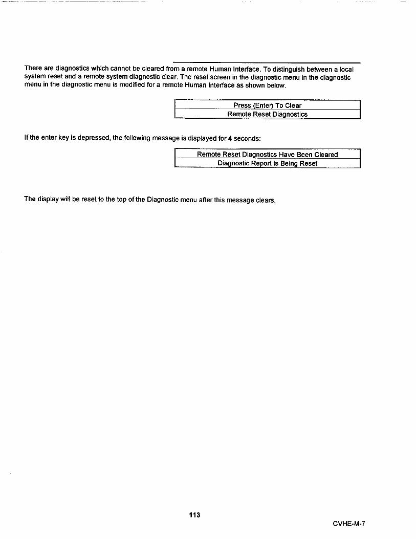
There are diagnostics which cannot be cleared from a remote Human Interface . To dist inguish between a localsystem reset and a remote system diagnostic clear . The reset screen in the diagnostic menu in the diagnosticmenu in the diagnostic menu is modified for a remote Human Interface as shown below .
Press (Ente r) To ClearRemote Reset Diag nostics
If the enter key is depressed , the follow i ng message is displayed for 4 seconds :
Remote Reset Diag nostics Have Been ClearedDiag nostic Report Is Being Reset
The display wil l be reset to the top of the Diagnostic menu after th i s message clears .
113CVHE-M-7


TRAA/E'M PeriodicMaintenance
Annual Inspection Check Li st and Report:CVHEs/CVHFs w/UCP2 Controls Panels
Review unit with ope rating pe rsonnel
Compressor Motor
[ ] Motor continuity checkGood [ ] Open [ ]
[ ] Check and tighten motor terminals
[ ] Meg motorPhase 1[] Phase 2[] Phase 3[ ]
[ ] Check nameplate ratingAmps [ ]
Starter
[] Check condition of starter contactsGood [ ] Fair [ ] Replace [ ]
Oil Sump
[ ] Change oilIf oil analysis, refer to programprocedures[ ] Gallons (7) required
[] Oil pump motor ground checkGood [ ] Open [ ]
[ ] Check motor terminals[ ] Change oil filter
Condenser
[] Visually inspect for scaling in tubes:note findings and makerecommendations.
Comments :
Control Circuits
[] Low refrigerant temperature sensor checkout
- F set point _ F trip point (ice water)
[] Leaving Evaporator water temperature sensorcheck out
- F set point _ F trip point (ice water)
[] Condenser High Pressure Switch check out_ psig setpoint_ psig trip point
[ ] Check Net Oil Pressure
[] Check adjustment and operation of inlet guidevane actuator stepper motor. The stroke of theactuator motor is 10,000 steps/inand approximately 50,000 steps pull stroke.
Leak Test Ch i ller
Refrigerant and oil analysis for acid content.
[] Sample refrigerant and oil for laboratory analysis (attach copy ofanalysis to next monthlyinspection report)
Purge Unit
[] Perform the purge system control check described in "ControlCircuit Diagnostics" in the "Troubleshooting" section of PRG-OM-5or most current edition of purge manual.
[] Perform Purge Tank check out and water removal as describedin "Service Procedures" of PRG-OM-5 or latest edition of purgemanual .
Recommendations :

UCP2 "SETTINGS GROUP" MEN U RECORD
OPERATOR SETTING GROUP :
Menu Item Choices Default Desi gn/Actual
1 Purge Operating Mode : Stop , On , Auto , Adaptive Adapt ive
2 Front Panel Chilled Wtr Setpt : 0->65 Deg F , -17 . 8->18 . 3 44 . 0 Deg F , 6 . 7 Deg C .De C
3 . Front Panel Current Limit Setpt : 40->100% 100%
4 Front Panel Hot Wtr ' Setpt : ( IF Hot water 80->125 Deg F , 26 . 7->51 . 7 90 Deg F , 32 . 2 Deg C
option Enabled ) Deg C
5 Free Cooling : (If Free Cooling Off , On Off
Option installed )
6 Chilled Water Reset Type : Disable , Return , Constant Disable
(If set to " Retum " or "Outdoor Air' , please refer Return , Outdoor Airto manual for settin p rocedure )
7 Ice Building : Disable , Enable Disable
8 Panel Ice Termination Setpoint : 20 - >32 Deg F , -6 . 7- >0 . Deg 27 Deg F . -2 . 8 Deg C .
Dis la ed if Ice Building Enabled ) C
9 Chilled Water Setpoint Source : Front Panel, Tracer , Remote Front Panel
Computer , External Source ,
External Direct Ca aci Cnt
10 Current Limit Setpoint Source : Front Panel , Tracer , Remote Front Panel
Computer , External Source
11 Hot Water Setpoint Source : Front Panel , Tracer , Remote Front Panel
(Displayed only if "Heat Pump" Controls Computer, External Source ,
enabled ) External Direct Ca aci Cnt
12 Heat Recovery Setpoint Source : Front Panel , Tracer , Remote Front Panel
(Displayed only if "Heat Recovery Option is Computer
installed )
13 Ice Termination Setpoint Source : Front Panel , Tracer, Remote Front Panel
(Displayed only if "Ice Building Option" i s Computer
installed )
14 Outdoor Air Temperature Source : UCP , Tracer UCP
SERVICE SETTINGS GROUP::Menu ftem Choices Defa u lt Desi g n/Actual
1 Language : English, Francais, Deutch, English
Espanol, Nippon, Italiano,Nederiands
2 Display Units: English, SI English
3 Decimal Places Displayed: XXX.X, XXX XXX.X
4 Display Menu Headings: Enable, Disable Enable
5 Differential To Start Setpoint: 1->10 Deg F, .5->5.5 Deg C 5 Deg F
6 Differential To Stop Setpoint: 1->10 Deg F, .5->5.5 Deg C 5 Deg F
7 Evap Pump Off Delay: 1->30 Minutes 1 Minute
Page 1

UCP2 "SETTINGS GROUP" MENU RECORD
FIELD STARTUP GROUP :
Menu ttem Choices Default Design/Actual
1 ICS Address : 0 - > 255 65
2 Design Delta Temp Setpoint : 4-> 30 Deg F , 2 . 2 -> 16 . 7 C 10 Deg F . 5 . 5 Deg C
3 Lvg Wtr Temp Cutout Setpoint : -10 - > 36 F , -23 . 2 - > 2 . 2 C 36 Deg F , 2 . 2 Deg C
(When this setpoint is wi thin 1 . 7 Deg F of theFront Panel Chilled Water Setpoint , the FrontPanel Chilled Water Setpoint is increased along
with this setpoint to maintain the differential )
4 Low Rfgt Temp Cutout Setpt : - 35 -> 36 F , - 37 . 2 - > 2.2 C 32 Deg F , 0 . 0 Deg C
(When this setpoint is within 6 Deg F of theFront Panel Chilled Water Setpoint , the FrontPanel Chilled Water Setpoint is increased alongwith this setpoint ot maintain the differential . )
5 Condenser Limit Setpo i nt : 80 -> 120 % 90 °/a
6 Maximum RI Timer Setiing : 30 -> 60 Minutes 60 Minutes
7 Purge Control/Type : 01 - Micro Purge 01 - Micro Purge
02 - W/Su ercha er
8 Purge Max Pumpout Rate : 1-> 100 Minutes / 24 Hours 12 Minutes / 24 Hours
9 Prg Disable Pumpout Alarm for: o-> 72 Hours 0 Hours
10 Prg Low Liq Temp Inhibit Enable : Enable , Disable Disable
11 Prg Low Liq Temp Inhibit Setpt : 32 -> 50 F , 0 . 0 -> 10 C 40 Deg F , 4 . 4 Deg C
(Does not display unless above feature =
" Enable"
12 Surge Protection : Disable , Enable Enable
13 Under/Over Voltage Protection : Disable , Enable Disable
(Permits "Enable" only if Option Installed )
14 Phase Reversal Protection : Disable , Enable Enable
15 Phase Unbalance Protection : Disable , Enable Enable
16 Momentary Power Loss Protection : Disable , Enable Enable
17 Oil Temp Setpoint : 100 -> 160 F , 37 . 8 -> 71 . 1 C 143 . 5 Deg F ,61 . 9 Deg C
18 Low Oil Temp Cutout : 80 -> 140 F , 26 . 7 -> 60 C 95 Deg F , 35 Deg C
19 High Discharge Temp Cutout : 170 ->220 F , 76 . 6 - > 104 . 4 C 200 Deg F , 93 . 3 Deg C
20 Control Type is : Chilled Water, Hot Water Chilled Water
21 Heat Pump Control : Disaable , Enable Disable
22 Control Sensitivity : Comfort , Process Comfort
23 External Vane Control Enable : Disable , Enable Disable
24 Soft Load Control : Disable , Enable Disable
25 Soft Load Starting Current Limit : 40 -> 100 % 100 %
26 Soft Load Current Limit Rate : 0 . 5 -> 5 . 0 % / Minute 5 . 0 % / Minute
27 Soft Load Lvg Water Rate : 0 . 5 -> 5 . 0 Deg F/Minute 5 . 0 Deg F/Min
0 . 3 -> 2 . 8 Deg C/Minute 2 . 8 Deg C/M i n
Hot Gas Bypass & Heat Recovery .See Manual if options are installed .
Page 2

UCP2 "SETTINGS GROUP" MENU RECORD
FIELD STARTUP GROUP : (Continued)
Menu Item Choice s Default Des i gn/Actual
28 IGV MAXIMUM Travel Setpt: 0-> 60,000 (100 Stepsllncr) 50,000 (90 Deg Vanes)
29 Guide Vane Open Travel Stop : 50 -> 100% 100 °/a
30 Guide Vane Closed Trave l Stop : 0-> 30 % 0%
31 Loca l Atmospheric Pressure : 10 -> 15 psia 1 4 .7 psi a
32 Unspecified Flag # 1: Disable, Enable Disable
33 Unspecified Type # 1 0 ->255 0.0
MACHINE CONFIGURATION GROUP :
Menu Item Choices Defautt Desig n/Actual
1 Unit Line Voltage : 180 -> 6600 (5 Volt incr) 460
2 Unit Frequency : 60 HZ, 50 HZ 60 HZ
3 Unit Type : CVH only(CVHEICVHF) CVH
4 Unit Tons : 100 ->1600 ( 10 Ton incr) 500
5 Refrigerant Type : R11 , R123 , R12 , R134a , R123Water . R22
6 Refri gerant Monitor Type : None , 01-Analog , 02-IPC None
7 Starter Type : Undefined , Variable Speed , Y-DeltaY-Delta , X-Line , Solid State ,Auto Xformer , PrimaryReactor
8 2nd Level Contactor Integrity Test : Disable , Enable Disable
(Startu p Contactor Test-Y - D Only)
9 Rated Load Amps : 0 -> 2 , 500 500
10 Motor Heating Constant : 0 - 100 Minutes 25 Minutes
11 Current Overload Setting # 1 : 00 -> 31 00
(See Manual for Setu p Procedure )
12 Current Overload Setting # 2 : 224 -> 255 255
(See Manual for Setup Procedure )
13 Maximum Accel Timer Setpt #1 : 6 -> 64 Seconds 27 Seconds
(See Manual for Recommended Set t
14 Maximum Accel Timer Setpt #2 : 191 -> 249 Seconds 228 Seconds
(255 Minus Timer Set t#1 above)
15 External Chilled Wtr Setpoint : " Installed , Not Installed Not Installed
16 External Current Limit Setpt : Installed , Not Installed Not Installed
17 External Hot Wtr Setpoint: Installed , Not Installed Not Installed
(Use only when "Hot Wtr Cnt is "Enabled")
18 Acceleration Time Out Action : Shutdown, Transition Shutdown
(Recommend "Shutdown" Only)
19 Motor Winding RTD Type : 70 Ohm/ 25 C , 100 Ohm/ 0 C 70 Ohm / 25 Deg C
20 High Pressure cutout setting : 0->500 PSIG (5 PSIG incr) 15 PSIG
(15 PSIG-Std , 25 PSIG-ASME)
21 Line Voltage Sensing Option : Installed , Not Installed Not Installed
Page 3

UCP2 "SETTINGS GROUP" MENU RECORD
MACHINE CONFIGURAT I ON GROUP : (Continued)
Menu Item Choices Default Desi gn/Actual
22 Auxiliary Condenser Option: Installed, Not Installed Not Installed
23 Heat Recovery Option: Installed, Not Installed Not Installed
24 Hot Gas Bypass Option: Installed, Not Installed Not Installed
25 Free Cooling Option: Installed, Not Installed Not Installed
26 Condenser Press. Sensor Option: Installed, Not Installed Not Installed
27 Bearing Temp Sensors Option: Installed, Not Installed Not Installed
28 Discharge Temp Sensor Option: Installed, Not Installed Not Installed
29 Ice Building Option: Installed, Not Installed Not Installed
30 Diff Wtr Press Sensor Opt: Inst, </= 150 PSIG, inst, Not Installed
( Both Eva p and Cond Sensors ) >150 PSIG, Not Installed
31 External Analog Inputs: 4-20 ma, 2-10 vdc 4-20 ma
32 Tracer Option: Installed, Not Installed Not Installed
33 Install TCI Option: Installed, Not Installed Not Installed
SERVICE TESTS GROUP :
Menu Item Choices Defa ult Design/Actual
1 Chilled Water Pump: Auto, On Auto
2 Condenser Water Pump: Auto, On Auto
3 Chilled Water Flow Switch:
4 Condenser Water Flow Switch:
5 Starter Dry Run:
See Manual for Procedures-Y-D only)
6 Oil Pump: Auto, On Auto
7 Vane Control is: Auto, Manual Auto
Page 4

01
CENTRAVAC WITH UCP2rJLWE TM
COMMISSIONING CHECKLIST &START-UP TEST LOG
Job Name Location
Model # Serial #
Sales Order # Start -up Date
N OTE: The Unit Installation, Operation and Maintenance Manuals, Submittals, and Design
Speci ficat i ons must be used i n conjunction w i th this checklist .
PRECOMMISSIONING PROCEDURESf]A. Obtain Installation Check SheetThis must be prepared by the installer for the particular unit, verifying the unit is ready for commissioning.[ ] B . Obtain Design (order) Specification Data
This indicates the design criteria of the particular unit. A unit cannot be properly commissioned unless this
data is known. It is the responsibility of the selling office to furnish this data.[; C. Obtain Wiring Diagrams
The "as-wired" electrical diagram should be compatable with the recommended Trane submittals and
diagrams. Are customer added external/remote control circuits compatable? ^ Yes ___^ No; ] D . General Installation Observations
Is there any apparent shipping or rigging damage? [', Yes __ _1 No
[_] 2 . Record the pressure on the sh i pping gauge PS IG . If there is no pressure on the gauge ,
a leak test w i ll have to be done before the unit can be evacuated and charged .
F_1 3 . Is the water piping correctly installed? q Yes ] No
Flow Switches q Yes qNo Pressure Gauges ^^^ Yes FA No
Isolation Valves F] Yes q No Flow Balancing Valves (.] Yes No
Thermometer Wells q Yes _] No Vent Cocks and Drains E: Yes I__J No
[-, 4 . Have proper clearances around the unit been maintained per submittal and/or Installation
Manual guidelines? q Yes r.) No
E7J 5 . Is power wiring of adequate ampacity and correct voltage? E Yes qNo
Are fuses or circuit breakers of the correct value or type? q Yes C No
^]6. Is the unit base acceptable, level, and is the unit on isolators (rubber as supplied by Trane or
spring type)? q Yes q No
rJ 7 . Have the micro (less than 30 volts) circuits been properly isolated from the higher voltagecontrol and power circuits? q Yes [] Na
[ E . Comments
Page 1

II . COMMISSIONING PROCEDURES
A. Pre-start ope ratio n s
1. Holding Charge
[] PSIG. Must be positive pressure or leak test must be done.
[j Relieve the holding charge.
2 . Calibration of High Pressure Cutout
qCalibrate the HPC to cut out when 15 PSIG is exceeded . The cut in value is
approximatly 10 PSIG . CUT OUT PSIG , CUT IN PSIG .
3 . Meggar the Motor (500 volt Meggar)
[]Compressor motor Megohms- refer to temp/resistance chart for acceptable values .
Remove surge suppresso rs before Megging . Never Meg test with the unit in a vacuum .
T1 to Earth T4 to Earth T1 to T2 T1 to T4
T2 to Earth T5 to Earth T1 to T3 T2 to T5
T3 to Earth T6 to Earth T2 to T3 T3 to T6
4 . Evacuation
f^Connect the vacuum pump to start evacuation . Use a 2-stage pump with at least 5 CFM
capacity . Connect to the evaporator charging valve with a hose no smaller than 3/4 i nch ID .
5 . Condenser
[]Isolation and flow balancing valves installed .
D Calibrated thermometers and pressure gauges installed in/out of condenser on machine
side of any valve or elbow .
q If condenser pump controlled by UCP2, is field wiring correct and complete?
q Condenser pump(s) run, system and strainers properly cleaned and/or flushed.
q Condenser water strainer in close proximity to entering connection of condenser.
q Provisions installed to properly maintain water treatment additives .
q Initial water treatment added to system .
q Flow or differential pressure switch installed and wired in series with auxiliary of
pump motor starter . Operation of circuit verified .
q Condenser water flow balanced . Ft H20 PD design , Ft H20 actual
GPM design GPM actual
Page 2

6 . Evaporator
1 i PSIG. Must be positive pressure or leak test must be done.
^--1 Calibrated thermometers and pressure gauges installed in/out of evaporator on machine
side of any valve or elbow.
[] If evaporator pump controlled by UCP2, is field wiring correct and complete?
I-_ ] Evaporator pump(s) run 24 hrs. System and strainers properly cleaned andlor flushed.
F Evaporator water strainer in close proximity to entering connection of evaporator.
U Provisions installed to properly maintain water treatment additives .
q Initial water treatment added to system .
q Flow or differential pressure switch installed and wi red i n series with auxiliary of
pump motor starter . Operation of circuit verified .
q Evaporator water flow balanced. Ft H20 PD design , Ft H20 PD actual
GPM design GPM actual
7 . Electri c al and Controls
a. Motor starter panel
[-] All terminals tightened.
q Wiring free from abrasion , kinks , and sharp corners .
q Contactors and relays have freedom of movement .
q All contacts are free of corrosion or dirt . Panel is free of dust , debris etc .
q Check the ratio of the current transformers . Record the part #s on the start-up log .
^ Use only twisted shielded pair for the IPC circuit between the starter and the UCP2 on
remote starters . Recommended wire is Beldon 8760 , 18 AWG . Polarity is critical .
q The low voltage IPC link (< 30 volts) must be in a separate conduit from the 115 volt wiring .
q I PC link routing within the starter panel must stay a minimum of 6 inches from higher voltages.
q Remote starter to UCP2 connections are complete and comply with Trane requirements.
q Check the correctness of the power connections from the starter to the motor.
q Check the wiring to the starter for size, voltage, and correct phase rotation (A-L1, B-L2, GL3).
[; Check for equal phase representation in each power wiring conduit.
Page 3

b. Control panel
I All terminals tightened.
II Wires free from abrasion, kinks, sharp corners.
f-_ I Low voltage wires are isolated from high voltage wires .
Cl Panel is free of debris, dust, etc.
[_l "Power up" the control panel.
1. Starter disconnect locked open.
2. Fuse 2F4 must be removed from the starter.3. Connect auxiliary 115VAC power cord to Terminals 1TB1-1 and 1T61-2 in the
control panel. MAKE SURE OF THE POLARITY . THE 'HOT' SIDE MUST BE
CONNECTED TO TERMINAL 1T61 -1 AND THE ' NEUTRAL' SIDE TO
1TB 1-2.
4. Plug in cord to 11 5VAC power source. Control panel is now energized.
q Record the settings found in the Operator Settings, Service Settings Field Start-up Group,and Machine Configuration Menus in the UCP2.
q Using the CVHE Operation and Maintenance manual and the order specification,
double check and reset, if required, the settings of Current Overload Setting #1 and
Current Overload Setting #2 found in the Machine Configuration menu of the UCP2.
NOTE : DO NOT FORGET TO ADJUST THE RLA RATING TO MATCH THE
ACTUAL JOBSITE VOLTAGE IF IT DIFFERS FROM THE DESIGN VOLTAGE .
If Evaporator and/or condenser water pumps are controlled by the UCP2, use the
Service Test menu of the UCP2 to manually start and test the control of the pumps.
q Check the setting of the oil pressure regulating valve.1. Use the Service Tests menu of the UCP2 to manually start the oil pump.2. Proceed to the Compressor Report menu of the UCP2 and observe the Differential
Oil Pressure.
3. Adjust the oil pressure regulating valve to maintain 12 to 18 psid. The oil pressureregulating valve may require adjustment as the unit is started.
4. This procedure also checks to ensure correct sensing of oil pressure. The Oil
Pressure Cutout setting is a non-adjustable 9 psid within the logic of the UCP2.
5. Return Oil Pump control to'auto'.
F-1 Check vane operator and vanes .
1 . Use the Service Tests menu of the UCP2 to manually overide the vane control .
2 . Enter targets from 0% to 100% and observe vane operation . At minimum and
maximum travel the operator should not exert any force on the vane assembly ,
adjust as required .
3 . Vane movement is smooth to open/close .4 . Vane movement is reported back to the UCP2 .
5 . Return Vane control to 'auto' .
Page 4
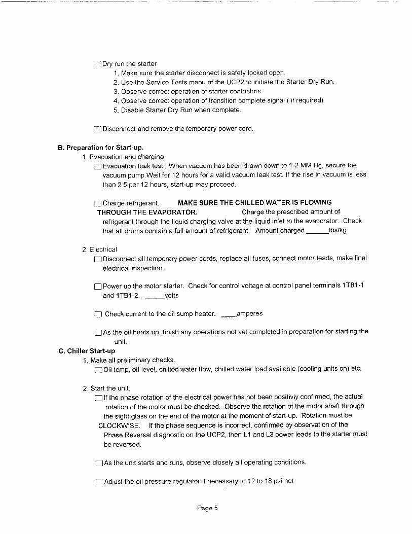
Dry run the starter
1. Make sure the starter disconnect is safety locked open.
2. Use the Service Tests menu of the UCP2 to initiate the Starter Dry Run.
3. Observe correct operation of starter contactors.
4. Observe correct operation of transition complete signal ( if required).
5. Disable Starter Dry Run when complete.
q Disconnect and remove the temporary power cord .
B . Preparation for Start -up .
1. Evacuation and charging
^ Evacuation leak test. When vacuum has been drawn down to 1-2 MM Hg, secure the
vacuum pump.Wait for 12 hours for a valid vacuum leak test. If the rise in vacuum is less
than 2.5 per 12 hours, start-up may proceed.
f:] Charge refrigerant. MAKE SURE THE CHILLED WATER IS FLOWING
THROUGH THE EVAPORATOR . Charge the prescribed amount of
refrigerant through the liquid charging valve at the liquid inlet to the evaporator. Check
that all drums contain a full amount of refrigerant. Amount charged Ibs/kg.
2. Electrical
q Disconnect all temporary power cords, replace all fuses, connect motor leads, make final
electrical inspection.
q Power up the motor starter . Check for control voltage at control panel terminals 1TB1-1
and 1TB1 -2 . volts
q Check current to the oil sump heater . amperes
F-] As the oil heats up , finish any operations not yet completed in preparation for starting the
unit .
C. Chiller Start-up
1. Make all preliminary checks.
q Oil temp, oil level, chilled water flow, chilled water load available (cooling units on) etc.
2 . Start the unit .
q If the phase rotation of the electrical power has not been positivly confirmed , the actual
rotation of the motor must be checked . Observe the rotation of the motor shaft through
the sight glass on the end of the motor at the moment of start-up . Rotation must be
CLOCKWISE . If the phase sequence is incorrect , confirmed by observation of the
Phase Reversal diagnostic on the UCP2 , then L1 and L3 power leads to the starter must
be reversed .
q As the unit starts and runs , observe closely all operating conditions .
!=! Adjust the oil pressure regulator if necessary to 12 to 18 psi net .
Page 5
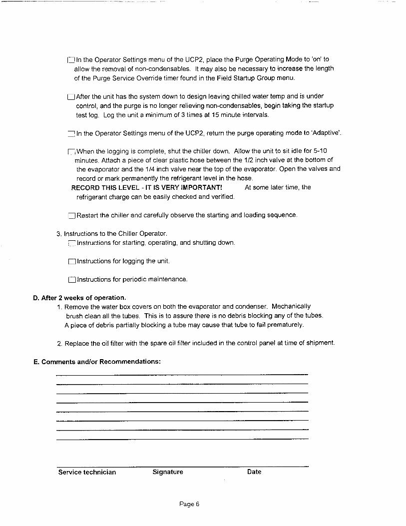
q In the Operator Settings menu of the UCP2, place the Purge Operating Mode to 'on to
allow the removal of non-condensables. It may also be necessary to increase the length
of the Purge Service Override timer found in the Field Startup Group menu.
q After the unit has the system down to design leaving chilled water temp and is under
control, and the purge is no longer relieving non-condensables, begin taking the startup
test log. Log the unit a minimum of 3 times at 15 minute intervals.
q In the Operator Settings menu of the UCP2 , return the purge operating mode to 'Adaptive' .
q When the logging is complete , shut the chiller down . Allow the unit to sit idle for 5-10
minutes . Attach a piece of clear plastic hose between the 1/2 inch valve at the bottom of
the evaporator and the 114 inch valve near the top of the evaporator . Open the valves and
record or mark permanently the refrigerant level in the hose .
RECORD THIS LEVEL - IT IS VERY IMPORTANT ! At some later time , the
refrigerant charge can be easily checked and verified .
0 Restart the chiller and carefully observe the starting and loading sequence .
3. Instructions to the Chiller Operator.
q Instructions for starting, operating, and shutting down.
q Instructions for logging the unit.
q Instructions for periodic maintenance.
D. After 2 weeks of operation .
1. Remove the water box covers on both the evaporator and condenser. Mechanically
brush clean all the tubes. This is to assure there is no debris blocking any of the tubes.
A piece of debris partially blocking a tube may cause that tube to fail prematurely.
2 . Replace the oil filter with the spare oil filter included in the control panel at time of shipment .
E. Comments and/or Recommendations:
Service technician Signature Date
Page 6

START-UP TEST LOGWATER COOLED CENTRAVACS WITH UCP2 CONTROL PANELS
Job Name Job Location
Model # Serial # Start Date
Sales Order # Ship Date Job Elevation (Ft above sea level)
STARTER DATA: START-UP ONLY
Manufacturer CHILLER CONDITION :
Type On Arrival:
(Star-Delta, X-Lin e, AutoTrans, Pri mary Reactor, Solid State Etc.) Machine Vacuum= mm (CVHE/F )
Vendor I D#/Model # Or
Volts Amps Hz q Machine Pressure=_psig (CVHE/F or RTHB)
MOTOR DATA : At Start-U p:
Manufacturer Machine Vacuum= mm
Type and Frame Or
Drawing # Machine Pressure=_psig
Serial # Complete If Pressure Test Is Required:
COMPRESSOR DATA: (RTH B units only) q Vacuum after Leak Check= mm
Model # Standing Vacuum Test= mm Rise in hrs
Serial # UNIT REFRIGERANT CHARGE :
NAMEPLATE DATA: lbs of R-
RLA KW Volts Hz HIGH PRESSURE CUTOUT (3S1) :
DESIGN DATA : (From Design Specification) Cut-In = psig Cutout = psig
RLA KW Volts Hz SUMMARY OF UNIT OPTIONS INSTALLED :
HEAT RECOVERY PERFORMANCE : q Tracer Communications Interface
RLA KW Vo l ts Hz Remote Clear Language Display Module
CURRENT TRANSFORMER Options Module
PART NUMBERS : (")C Code & 2 Digit Extension) q Outdoor Air Sensor
Primary CT's: q Enhanced Condenser Limit Control
X q Heat Recovery / Aux Condenser
X - -] Free Cooling Control
X - F- Hot Gas Bypass Control
Secondary CTs: q Ice Making Control
X - q Monitoring Package
X - Bearing Oil Temp Sensors
X Discharge Temp Sensor
( N ote, secondary CTs are used only on remote ^ Compressor Phase Volt Sensors
starters "by others" & high voltage applications) - Other
Also complete the Commissionin g Checklist, Record Sheet, and Start-up/Operation Log .
Page 1
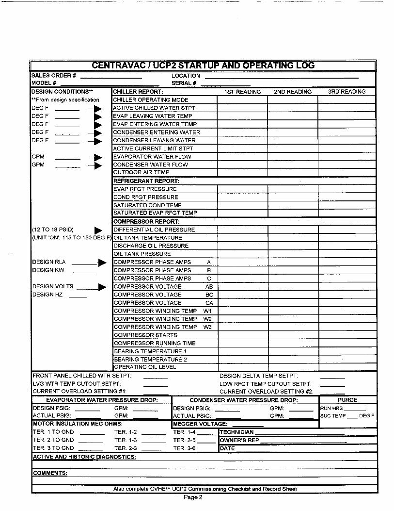
CENTRAVAC 1 UCP2 STARTUP AND OPERATING LOG
SALES ORDER # LOCATION
MODEL # SERIAL #
DESIGN CONDITIONS*' CHILLER REPORT: 1ST READING 2ND READING 3RD READING
** From des i g n specification CHI LLER OPERAT I NG MODE
DEG F ACT IVE CH I LLED WATER STPT
DEG F EVAP LEAVI NG WATER TEMP
DEG F EVAP ENTERI NG WATER TEMP
DEG F CONDENSER E NTER I NG WATER
DEG F CONDENSER LEAVI NG WATER
ACTIVE CURRENT LIMIT STPT
GPM EVAPORATOR WATER FLOW
GPM -^ CONDENSER WATER FLOW
OUTDOOR AIR TEMP
REFRIGERANT REPORT:
EVAP RFGT PRESSURE
COND RFGT PRESSURE
SATURATED COND TEMP
SATURATED EVAP RFGT TEMP
COMPRESSOR REPORT:
( 1 2 TO 1 8 PS I D) --Jp, DIFFERENTIAL OIL PRESSURE
(UN I T 'O N ', 1 1 5 TO 150 DEG F) OI L TANK TEMPERATURE
DISCHARGE OIL PRESSURE
OI L TANK PRESSURE
DESIGN RLA COMPRESSOR PHASE AMPS A
DESIGN KW COMPRESSOR PHASE AMPS B
COMPRESSOR PHASE AMPS C
DESIGN VOLTS COMPRESSOR VOLTAGE AB
DESIGN HZ COMPRESSOR VOLTAGE BC
COMPRESSOR VOLTAGE CA
COMPRESSOR WINDING TEMP W1
COMPRESSOR WI ND I NG TEMP W2
COMPRESSOR WIND I NG TEMP W3
COMPRESSOR STARTS
COMPRESSOR RUNN I NG T I ME
BEARING TEMPERATURE 1
BEAR I NG TEMPERATURE 2
OPERATING OIL LEVEL
FRONT PANEL CH I LLED WTR SETPT: DESIG N DELTA TEMP SETPT :
LVG WTR TEMP CUTOUT SETPT: LOW RFGT TEMP CUTOUT SETPT:
CURRENT OVERLOAD SETTI NG #1 : CURRENT OVERLOAD SETTI NG #2:
EVAPORATOR WATER PRESSURE DROP : CONDENSER WATER PRESSURE DROP : PURGE
DESIGN PSIG: GPM : DESIGN PSIG: GPM : RUN HRS
ACTUAL PSI G: GPM : ACTUAL PSIG : GPM : SUC TEMP DEG F
MOTOR INSULATION MEG OHMS : MEGGER VOLTAGE:
TER . 1 TO GND TER . 1-2 TER . 1-4 TECHNICIAN
TER. 2 TO GND TER. 1-3 TER. 2-5 OWNERS REP
TER . 3 TO GND TER . 2-3 TER . 3-6 DATE
ACTIVE AND HISTORIC DIAGNOSTICS :
COMMENTS:
Also complete CVHE/F UCP2 Commissioning Checklist and Record Sheet
F'age 2


![Trane CVHE,F,G-SB-33C[1]](https://static.fdocuments.in/doc/165x107/54f8233f4a79590a4e8b497c/trane-cvhefg-sb-33c1.jpg)