Operation and Maintenance Manual - Nordco | Home · HYDRA-Lift . Operation and . Maintenance ....
41
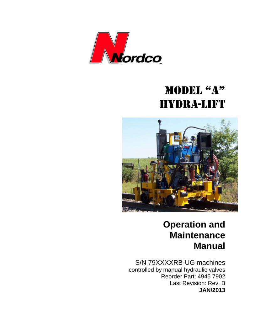
MODEL “A” HYDRA-Lift Operation and Maintenance Manual S/N 79XXXXRB-UG machines controlled by manual hydraulic valves Reorder Part: 4945 7902 Last Revision: Rev. B JAN/2013
Transcript of Operation and Maintenance Manual - Nordco | Home · HYDRA-Lift . Operation and . Maintenance ....
MODEL “A” HYDRA-Lift
Operation and Maintenance
Manual
S/N 79XXXXRB-UG machines controlled by manual hydraulic valves
Reorder Part: 4945 7902 Last Revision: Rev. B
JAN/2013
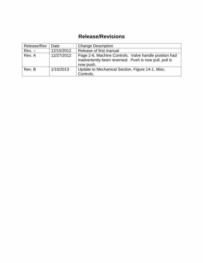
Release/Revisions
Release/Rev Date Change Description Rev. -- 12/15/2012 Release of first manual Rev. A 12/27/2012 Page 2-6, Machine Controls. Valve handle position had
inadvertently been reversed. Push is now pull, pull is now push.
Rev. B 1/15/2013 Update to Mechanical Section, Figure 14-1, Misc. Controls.

This manual is a guide for the operation and routine maintenance of a NORDCO Railroad Maintenance Machine. It covers product technical information, basic operating and maintenance procedures, and safety information and is provided for use by the qualified personnel who will supervise, operate or service the equipment described herein. Measurements in this manual are given in both metric and customary U.S. unit equivalents. Personnel responsible for the operation and maintenance of this equipment should thoroughly study the manual before commencing operation or maintenance procedures.
This manual should be considered a permanent part of your machine and should remain with the machine at all times. Additional copies of this manual are available either as a part (Operation Manual only) or a whole (operation and parts manual), at a nominal cost, through our Part Sales Department. Additional service information, parts, and application information is available through these Nordco product support resources:
NORDCO Sales: Milwaukee, Wisconsin (414) 766-2180
[email protected] NORDCO Parts: Milwaukee, Wisconsin
1-800-647-1724 [email protected]
NORDCO Service: 1-800-445-9258 [email protected]
We ask that if you have any comments or suggestions about this manual, let us hear from you. We are here to be of service to you, our customers. Direct your comments and inquiries to:
Technical Documentation Department
NORDCO Inc. 245 W. Forest Hill Avenue
Oak Creek, WI 53154

HAZARDOUS MATERIAL DATA In an effort to provide information necessary for your employee safety training program and to meet the requirements of OSHA Hazard Communication Standard 1910.1200, we have OSHA Form 20 Safety Data Sheets available that cover the material contained in this machine. If you are interested in receiving this information, please refer to the Name, model, and Serial Number of your machine when calling or writing, and direct your inquiries to:
Vice-President of Operations
NORDCO Inc. 245 W. Forest Hill Avenue
Oak Creek, WI 53154
Fax: (414) 766-2299 Phone: (414) 766-2288

Hydra-Lift Model “A” CONTENTS
DEC/2012 (49457902) i Contents
TABLE OF CONTENTS SECTION 1 – SAFETY & GENERAL INFORMATION SAFETY ..................................................................................................................................................... 1-1 Understanding Key Safety Alert Words Follow Safety Instructions ...................................................................................................................... 1-1 General Safety Tips ............................................................................................................................... 1-2 Safety Alerts ........................................................................................................................................... 1-4 Lockout/Tagout Requirements .............................................................................................................. 1-5 Lockout/Tagout Procedures................................................................................................................... 1-6 GENERAL INFORMATION ....................................................................................................................... 1-9 SPECIFICATIONS ................................................................................................................................... 1-10 SECTION 2 - OPERATION BEFORE OPERATION Basic Description ....................................................................................................................................... 2-1 Hydraulic System................................................................................................................................. 2-1 Logic Box Control Panel ...................................................................................................................... 2-1 Detailed Descriptions ................................................................................................................................. 2-2 Main Control Panel – Engine and Pump Controls (Includes Horns and Lights)l ................................. 2-3
Machine Controls ................................................................................................................................ 2-6 Remote Controls and Indicators .......................................................................................................... 2-7
PREPARING THE MACHINE FOR WORK .............................................................................................. 2-8 Pre-Operational Checklist ................................................................................................................... 2-9 Engine Operation .............................................................................................................................. 2-10 Startup Checks .................................................................................................................................. 2-10 LOCKUP DEVICES ................................................................................................................................. 2-11 TRAVEL Engine Speeds .................................................................................................................................. 2-12 Propelling and Braking ...................................................................................................................... 2-12 MACHINE OPERATION Work Operation ................................................................................................................................. 2-13 Emergency Procedures ..................................................................................................................... 2-13 Emergency Stopping ......................................................................................................................... 2-13 AFTER OPERATION Normal Shutdown .............................................................................................................................. 2-14 Parking or Locating Machine ............................................................................................................. 2-14 Towing ............................................................................................................................................... 2-14 SECTION 3 - MAINTENANCE AND SERVICE NORDCO’S SERVICE NETWORK (REQUESTING ASSISTANCE) ........................................................ 3-1 SAFETY DURING MAINTENANCE .......................................................................................................... 3-2 RECOMMENDED LUBRICANTS ............................................................................................................. 3-3 LUBRICATION AND MAINTENANCE CHART ........................................................................................ 3-4 LUBRICATION AND MAINTENANCE INSTRUCTIONS .......................................................................... 3-5 MAINTENANCE FOR EXTREME CONDITIONS...................................................................................... 3-7

CONTENTS Hydra-Lift Model “A”
Contents ii DEC/2012 (49457902)
PARTS SHEETS MECHANICAL TAB OPERATOR CONTROLS Plate Pusher Assembly ........................................................................................................................................ 79C-1A-2 AXLE AND AXLE ACCESSORIES Drive Axle Assembly (Dual Axle Drive) ................................................................................................................ 79C-2A-1 BRAKES (Optional) Parking Brake ......................................................................................................................................................... 79C-3A PROPULSION AND DRIVE Dual Axle Drive System ............................................................................................................................................ 79C-5 FRAME ACCESSORIES Batteries ................................................................................................................................................................ 79C-6-1 Lights and Horns .................................................................................................................................................... 79C-6-2 Decals, Plaques and Charts .................................................................................................................................. 79C-6-3 Jackstands and Bumpers ...................................................................................................................................... 79C-6-4 Miscellaneous Optional Equipment (Vises, Extinguishers, etc.) ............................................................................ 79C-6-5 ENGINE AND PUMPS Deutz FL2011 and Options .............................................................................................................................. 79C-7-DE-1 Deutz D2011L02i (Before S/N 791039) ........................................................................................................... 79C-7-DE-2 Deutz D2011L02i (S/N 791039 and Above) ................................................................................................... 79C-7-DE-2A Hatz 2L41CB w/Silent Pak ............................................................................................................................... 79C-7-HA-1 Hatz 2M41Z (BNSF Engines Only) .................................................................................................................. 79C-7-HA-2 Hatz 2M41ZC .................................................................................................................................................. 79C-7-HA-3 Pump and Pump Drive ........................................................................................................................................ 79C-7-P-2 HYDRAULIC TANKS 38 Gallon Tank (Option) ...................................................................................................................................... 79C-8-1A 30.5 Gallon Tank (Standard) ............................................................................................................................... 79C-8-2A OIL COOLER ...................................................................................................................................................... 79C-09-1 FUEL TANKS 10.5 Gallon (Standard)......................................................................................................................................... 79C-10-1 18 Gallon (Optional) ............................................................................................................................................. 79C-10-2 WORKHEAD ASSEMBLIES Rail Lift Assembly ............................................................................................................................................. 79C-13-1-2 Rail Clamp Assembly Insulated ..................................................................................................................................................... 79C-13-2-1 Non-Insulated ............................................................................................................................................. 79C-13-2-2 HYDRAULIC TAB HYDRAULIC SYSTEM ADJUSTMENTS ............................................................................................. Hydraulic Preface FUNCTIONAL HYDRAULIC SCHEMATICS S/N 79XXXRB-UG and Above ............................................................................................................ 97790004DWG ELECTRICAL TAB
Hydra-Lift Model “A” CONTENTS
DEC/2012 (49457902) iii Contents
ELECTRICAL SCHEMATICS S/N 79XXXRB-UG and Above ............................................................................................................ 97791005DWG LOGIC BOX

Hydra-Lift Model A SAFETY
DEC/2012 (49457902) Section 1-1
SAFETY Please read and comply with all of the safety precautions in this manual BEFORE operating this machine. GENERAL DO NOT use this machine for machine operations other than for which it was intended. NORDCO is not responsible for any modifications made without authorization or written approval. Replace all NORDCO and OEM parts with genuine NORDCO or OEM parts. Use of non-OEM parts could compromise the safety of your machine. FRA regulations require that a copy of this Operation Manual be kept on the machine at all times. Additional copies of the Operation Manual only can be ordered from Nordco Parts Sales at 1-800-647-1724. FOLLOW SAFETY INSTRUCTIONS Carefully read all safety messages in this manual. Learn how to operate the machine and how to use controls properly. Do not let anyone operate this machine without instruction. Failure to understand the contents of this manual could result in serious personal injury or death.
SAFETY ALERT SYMBOLS! These are the safety-alert symbols.
These symbols means pay attention! Your safety is at risk!
DANGER is used to indicate a definite hazardous situation which, if not avoided, WILL result in severe bodily harm or even death.
WARNING indicates a potentially hazardous situation which, if not avoided, COULD result in severe bodily harm or even death.
CAUTION indicates a potentially hazardous situation which, if not avoided, MAY result in minor or moderate injury.
CAUTION without the safety “!” means that failure to follow the alert may result in machine damage.
SAFETY means that the following points are instructions for safely operating the machine or the specific component of the machine.
SAFETY Hydra-Lift Model A
Section 1-2 DEC/2012 (49457902)
GENERAL SAFETY TIPS Only trained and authorized personnel should be allowed to operate this machine. In addition, all personnel at the worksite (gang) should be aware of the safety concerns and their individual responsibilities prior to working this machine.
1. Handle fuel safely. It is highly
flammable and prolonged breathing of fumes may cause bodily harm.
2. Prepare for emergencies. Keep a
first aid kit and fire extinguisher handy.
3. Protect against flying pieces of
metal and debris by wearing safety glasses or goggles.
4. Wear good-fitting pants and shirt,
no baggy or loose clothing. 5. Protect your head and eyes from
flying debris by wearing a hard hat and safety goggles/glasses.
6. Wear leather gloves to protect your
hands from vibration or flying metal particles.
7. Use safety-toed work boots. SAFETY PRIOR TO WORKING All personnel at the worksite (gang) should be aware of the safety concerns and their individual responsibilities prior to working this machine:
• Review the operating instructions if you are unsure of anything.
• Use the “pre-operational checklist” to check the machine for obvious faults. Repair or replace as necessary PRIOR to operating the machine.
• Before climbing onto the machine, make certain the area around and
under the machine is clear of obstructions and personnel.
• Use care when climbing onto the machine. Always use the steps and handrails provided. (If an area does not have tread grips, walkways, or other methods to access the area, then DO NOT attempt to access that area.)
• Make seat and control adjustments PRIOR to starting the machine. ALWAYS wear a seatbelt.
• Know the weather forecast and plan your work speeds accordingly.
• There are guards on this machine. These are to be removed ONLY when service or maintenance is being performed on that area of the machine. Make certain they have been re-installed PRIOR to starting the machine.
• Check and service the fire extinguisher (if so provided) at regular intervals. Make certain all personnel are trained in its use. Note - Non-use of fire extinguisher still requires that it be recharged at the interval stated on its last inspection notice.
• Keep the stairs, cab entry platform and cab interior free and clear of ice, tools and personal items. Use the accessories provided on the machine (tool box, cup holder, coat hook, etc.) to properly store your gear.
• Never climb onto the machine while it is in motion.
• There are lockups on this machine that are used for both work and travel. These should be kept clear and free of debris, grease, etc. See Lockup section for instructions on their use.
• Inspect safety decals and replace when they become unreadable or are damaged. (See “Safety Decals” at the end of this Safety section).

Hydra-Lift Model A SAFETY
DEC/2012 (49457902) Section 1-3
SAFETY WHILE STARTING THE MACHINE NORDCO recommends the use of a Command position. This means that the machine is never running unless someone is at or near the main control panel or remote control boxes. To prevent injury to personnel or damage to the machine, it is highly recommended to:
1. Only start and operate the machine from the operator’s seat.
2. Use the “STARTUP Checklist” to
check the machine controls and gauges to make certain all systems are operating correctly.
SAFETY WHILE OPERATING/TRAVELING
1. Never allow more riders than seats and
seatbelts allow. This machine was designed to be operated by one person.
2. The machine is to be operated from
the Operator’s seat only. Do NOT stand and operate this machine.
3. Press the EMERGENCY STOP
pushbutton on the center control console in emergencies and potentially dangerous situations.
4. If personnel or bystanders are near the
machine during operation, give a warning signal using the air horn. If they fail to respond to this warning, stop operation immediately.
5. Slow down the work cycle and use
slower travel speeds in congested or populated areas.
6. Halt work if visibility is poor. Strong
rains, fog, and extremely dusty conditions can affect visibility in your work area. Wait for the weather to improve before continuining work.
SAFETY WHILE PARKED When leaving a machine engine running, make certain that the parking brake is applied and the electrical interlock button has been activated. NEVER stop and park this machine on an incline unless the machine wheels have been chocked. SAFETY DURING MAINTENANCE The following guidelines are suggested when performing maintenance:
1. Always chock the wheels 2. Alert others in the area that service
or maintenance is being performed on this machine.
3. Become familiar with, and use, your company’s lockout/tagout procedures when performing maintenance on this machine. See LOCKOUT/TAGOUT REQUIREMENTS later in this Safety Section for a chart on energy sources located on this machine.
4. Do not start the engine if repairs or work is being performed alone. You should always have at least two people working together if the engine must be run during service. One person needs to remain in the command position (at the controls), ready to stop the machine and shut off engine if the need arises.
5. Collect oils and fuels and dispose of them properly. There is a danger of scalding when working with engine oils.
6. Use only Nordco supplied repair parts for this machine. Use of non-OEM designed parts could comprise the integrity of this machine.
7. There are welding cautions on this machine. Pay attention to them PRIOR to welding.
8. Kits supplied by Nordco have welding instructions included. Welding of any components NOT of Nordco’s manufacture or failure to follow these instructions may affect the stability of this machine.

SAFETY Hydra-Lift Model A
Section 1-4 DEC/2012 (49457902)
MACHINE SAFETY ALERTS
DANGER ALERTS Improper use of this machine for any type of operation can cause
serious injury or death. To avoid serious injury or death, make certain that the area around and under the machine is clear of all personnel and obstructions BEFORE travelling or working.
Serious injury or death can result from reaching into working components while machine is running. Make all observations from a distance and SHUT OFF machine while making adjustments. Shut off engine when checking battery electrolyte level. Do not check or fill battery in presence of open flame, sparks, or when smoking. Battery fumes are flammable and/or explosive and if ignited will result in severe bodily injury or death. Do not ride on tow bar between the machine and the towing vehicle. Falling from a moving vehicle may cause serious injury or death.
Never Ride on This Machine.
MACHINE SAFETY ALERTS
WARNING ALERTS
Failure to engage all lockup devices before propelling at travel speed can result in injury to personnel and/or extensive damage to the machine. Remove hoses/fittings only when system is not pressurized. High pressure leaks can cause personal injury. Always turn off machine when performing maintenance, making adjustments, or whenever unintended movement of machine could occur; unless directed otherwise. Failure to comply could result in personal injury and/or damage to the machine. Exhaust emissions caused by the use of the engine on this machine may cause cancer, birth defects, or other reproductive harm if inhaled. Disconnect the battery before servicing this machine. Failure to do so could result in personal injury from accidental engine startup.

Hydra-Lift Model A SAFETY
DEC/2012 (49457902) Section 1-5
LOCKOUT AND/OR TAGOUT REQUIREMENTS The following list suggests lockout procedures to use on all components of the machine that require lockout due to the storage of various forms of energy. It is your company’s responsibility to Lockout/Tagout Procedures based on this list, train you in their proper and safe use, and to periodically inspect your work area to verify that you are complying with the procedures. Lockout/Tagout Procedures must be followed! NORDCO has provided the means to lockout this machine. NORDCO cannot be held responsible for injury caused by failure to comply with your company’s Lockout/Tagout Procedures. See next page for suggested lockout/tagout procedure list.

SAFETY Hydra-Lift Model A
Section 1-6 DEC/2012 (49457902)
LOCKOUT-TAGOUT PROCEDURES The following procedures are designed to lead the operator through the steps required to shut the machine down and prepare it for performing mechanical maintenance work. These procedures are intended to release potentially dangerous stored energy forms and make the machine safe to begin repairs.
SAFETY PROCEDURES LOCKOUT/TAGOUT
1. Apply Parking Brake. 2. Chock wheels to prevent accidental rolling of machine on grade. 3. If you have not already done so, determine which components
are to have maintenance. Place all machine mechanical systems or workheads in the full up and locked positions.
4. Refer to the list at the bottom of the page to determine what procedures are required when mechanical locking up of equipment is not feasible for maintenance. Then continue on with Steps 5-8.
5. Turn the ignition switch to the OFF position. This turns off the power to the control circuits on the machine. Place a TAGOUT card in close proximity to the ignition switch.
6. Turn the battery disconnect switch (BDS) to the OFF position. a. For machines with the BDS on the left side of the center
(front) control console: Place a TAGOUT card on the switch after you have switched it to the OFF position.
b. For machines with a remotely located BDS (usually next to the battery box itself): Close the cover to the disconnect switch and place a LOCKOUT lock on the box after you have switched it to the OFF position.
7. Bleed off hydraulic pressure. 8. Follow all of your company’s lockout/tagout rules before
proceeding. Note: When working on machine components, be aware that moving components during repairs may create energy (ie., moving a hydraulic cylinder). Proper precautions should be taken.
This list is for specific components in an assembly, where maintenance cannot be performed with the assembly in the full up and/or locked position. After completing the steps required, continue on with Steps 5-8 above.
When performing maintenance on: Secure as follows: RAIL CLAMP ASSEMBLY Rail Lift Up/Down Cylinder Lower Rail Clamp Assembly to rail. Rail Clamp In/Out Cylinder Lower Rail Clamp Assembly to rail and
place a support under the rail clamp lever.

Hydra-Lift Model A SAFETY
DEC/2012 (49457902) Section 1-7
SAFETY DECALS ON THIS MACHINE Safety decals and plaques that have been placed on this machine are to be kept clean and legible. Replace any decals or plaques that have become illegible or are missing. When repairing or replacing components that had safety decals on them, it is your responsibility to replace the safety decals. These can be ordered from the Parts Sales Department. Safety Decals on this Machine are:
PART NO. DESCRIPTION LOCATION
5642 0002 Caution! Watch Your Step Frame, by Step 5642 0004 Danger! Pinch Points On Rail Clamps 5642 0005 Warning! Hand Hazard On Rail Clamps 5642 0006 Danger! Before Servicing... Logic Box Sides 5642 4501 Caution! Before Welding... Logic Box Face
Battery Box 5642 0010 Lockout Area Logic Box Face 5642 0011 Lockout Area Battery Box 5642 0012 Lockup Points All areas requiring
Lockups for travel.

SAFETY Hydra-Lift Model A
Section 1-8 DEC/2012 (49457902)
This page intentionally left blank

Hydra-Lift Model “A” GENERAL
Section 1-9 DEC/2012 (49457902)
GENERAL This manual contains operation and maintenance information for the MODEL “A” HYDRA-LIFT manufactured by NORDCO INC., Oak Creek, Wisconsin. Information regarding the operation and maintenance of this machine can be found behind the appropriate tabs. Information regarding operation and maintenance of OEM parts not of NORDCO manufacture can be found at the back of this manual, behind the tab marked Component Data. Become familiar with all safety instructions, controls and instruments before operating this machine. Follow all instructions carefully. ABOUT THIS MANUAL This manual has been broken down into sections which have been separated by index tabs: This manual has been broken down into sections which have been separated by index tabs:
Mechanical has individual parts breakdown drawings and lists for each assembly Hydraulic includes adjustment instructions and troubleshooting for the hydraulic system; and all piping and functional drawings for a standard machine and optional equipment Electrical, includes all electrical schematics, logic box, control box, and cable drawings for the machine; and troubleshooting instructions Component Data includes parts breakdowns and service instructions for components installed on the machine that are not of NORDCO’s manufacture

GENERAL Hydra-Lift Model “A”
DEC/2012 (49457902) Section 1-10
SPECIFICATIONS GENERAL Model ........................................................................................................................................................ Model A Gross Weight* ......................................................................................................................................... 4000 lbs Length .................................................................................................................................................... 92 inches Width ...................................................................................................................................................... 72 inches Height Hatz Engine ......................................................................................................................................... 97 inches Deutz Engine ............................................................................................................ Not Available at This Time Wheel Base ............................................................................................................................................ 50 inches Working Clearance (from center of track) .................................................................................... 5 feet 10 inches Travel Speed (Variable) ............................................................................................................................... 4 mph CAPACITIES Fuel Tank (Painted Green) ...............................................................10 gallons (Standard), 18 gallons (Optional) Hydraulic Oil Tank (Painted Blue) ........................................................................................ 30 gallons (standard) Plate Storage ............................................................................................................................. 35 plates on deck ENGINE (VARIES ACCORDING TO S/N OF REBUILT MACHINE) Make/Model (Current S/N Machines) ................................................................................................. Hatz 2M41Z Type ........................................................................................................... 4 Cycle, 2 Cylinder, Air Cooled Diesel Continuous BHP ................................................................................................ 23 HP @ 2050 RPM, Under load Low Idle/High Idle ................................................................................................................... 1150 rpm/2140 rpm Make/Model (Current S/N Machines) ................................................................................................. Hatz 2L31C Type ........................................................................................................... 4 Cycle, 2 Cylinder, Air Cooled Diesel Continuous BHP ................................................................................................ 21 HP @ 2050 RPM, Under load Make/Model (Current S/N Machines) ................................................................................................. Hatz 2L40C Type ........................................................................................................... 4 Cycle, 2 Cylinder, Air Cooled Diesel Continuous BHP ................................................................................................ 23 HP @ 2050 RPM, Under load Make/Model (Current S/N Machines) ........................................................................................................... Deutz Type ........................................................................................................... 4 Cycle, 2 Cylinder, Air Cooled Diesel Continuous BHP ................................................................................................ 23 HP @ 2050 RPM, Under load Low Idle/High Idle ................................................................................................................... 1150 rpm/2140 rpm Make/Model (Current S/N Machines) .............................................................................................. Deutz F1L210 Type ........................................................................................................................................... Air Cooled Diesel Continuous BHP ............................................................................................. 12.5 HP @ 2800 RPM, Under load Make/Model (Current S/N Machines) ............................................................................................ Deutz F2L1011 Type ........................................................................................................... 4 Cycle, 2 Cylinder, Air Cooled Diesel Continuous BHP ................................................................................................ 23 HP @ 2300 RPM, Under load Items or capacities may vary according to options on your machine. * Approximate weight. Actual weight may vary according to options on your machine. Actual weight of your machine is as stenciled.
Hydra-Lift Model “A” GENERAL
Section 1-11 DEC/2012 (49457902)
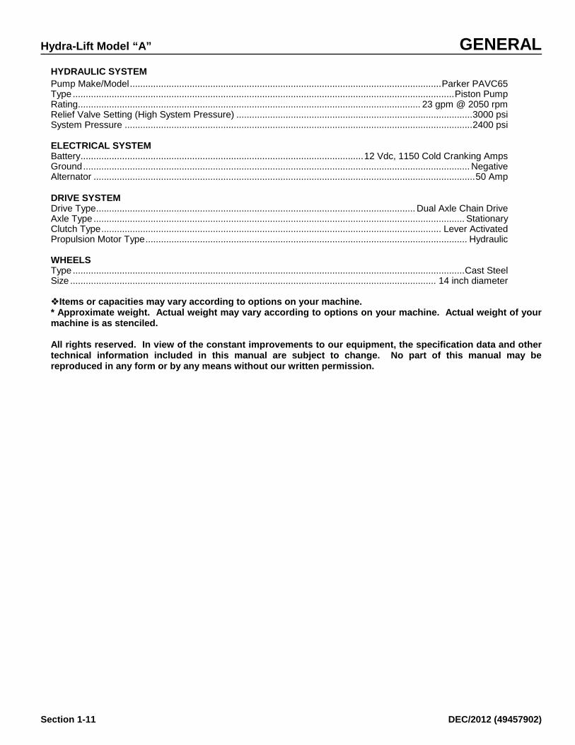
HYDRAULIC SYSTEM Pump Make/Model ........................................................................................................................ Parker PAVC65 Type ................................................................................................................................................... Piston Pump Rating .................................................................................................................................... 23 gpm @ 2050 rpm Relief Valve Setting (High System Pressure) ........................................................................................... 3000 psi System Pressure ...................................................................................................................................... 2400 psi ELECTRICAL SYSTEM Battery ............................................................................................................. 12 Vdc, 1150 Cold Cranking Amps Ground ..................................................................................................................................................... Negative Alternator ................................................................................................................................................... 50 Amp DRIVE SYSTEM Drive Type ........................................................................................................................... Dual Axle Chain Drive Axle Type ............................................................................................................................................... Stationary Clutch Type ................................................................................................................................... Lever Activated Propulsion Motor Type ............................................................................................................................ Hydraulic WHEELS Type ....................................................................................................................................................... Cast Steel Size ............................................................................................................................................. 14 inch diameter Items or capacities may vary according to options on your machine. * Approximate weight. Actual weight may vary according to options on your machine. Actual weight of your machine is as stenciled. All rights reserved. In view of the constant improvements to our equipment, the specification data and other technical information included in this manual are subject to change. No part of this manual may be reproduced in any form or by any means without our written permission.

GENERAL Hydra-Lift Model “A”
DEC/2012 (49457902) Section 1-12
This page intentionally left blank

Hydra-Lift Model “A” OPERATION
DEC/2012 (49457902) Section 2-1
Before operating this machine, read and understand the Safety Section of this Manual. BEFORE OPERATION It is always good practice to become totally familiar with the machines you are going to operate.
IMPROPER USE OF THIS MACHINE FOR ANY TYPE OF OPERATION CAN CAUSE SERIOUS INJURY OR DEATH. BASIC DESCRIPTION This machine can be manually operated by either one or two operators using valve banks to perform work operations. Rail lifting and clamping is done through the use of the valve banks and the plate pushing is done using a manual plate pusher.
THIS MACHINE IS NOT EQUIPPED WITH SEATS OR SEATBELTS. DO NOT RIDE ON OR ALLOW OTHERS TO RIDE ON THIS MACHINE WHEN WORKING, TRAVELLING, OR TOWING. FAILURE TO COMPLY COULD RESULT IN SEVERE PERSONAL INJURY OR DEATH. This machine is not designed for passengers during work or travel operations. There are no seats or seatbelts provided on this machine. DO NOT RIDE ON THIS MACHINE! HYDRAULIC SYSTEM The hydraulic system uses one manifold and a series of valve banks to control machine working functions. More detailed information regarding the hydraulic system and manifolds is located behind the tab marked “HYDRAULICS”. The hydraulic pump is a pressure compensated, variable displacement, radial piston type, providing high flow and pressure. Refer to the preface of the Hydraulic Section of this manual for more information on the hydraulic system and it’s adjustments.
LOGIC BOX CONTROL PANEL The logic box control panel houses all of the operator selectable items on the machine. The logic box drawing on the next page is representative of a standard machine. Become familiar with its functions.

OPERATION Hydra-Lift Model “A”
Section 2-2 DEC/2012 Rev A (49457902)
MAIN CONTROL PANEL (LOGIC BOX)
Hydra-Lift Model “A” OPERATION
DEC/2012 (49457902) Section 2-3
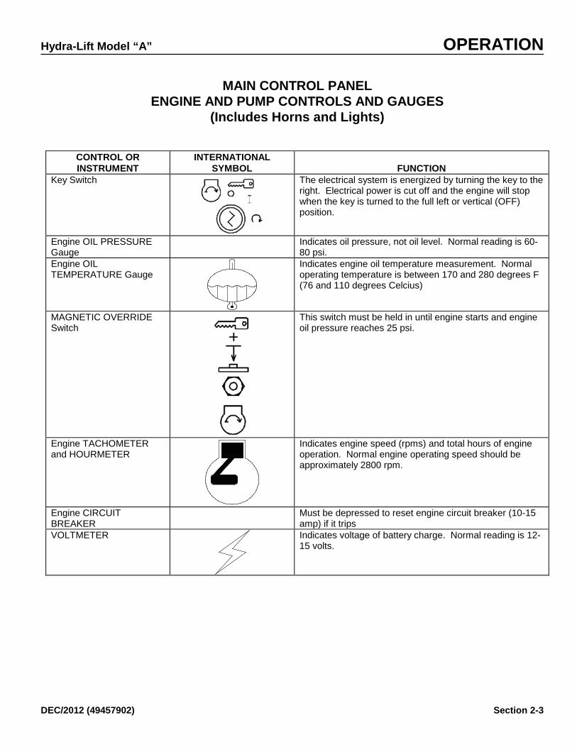
MAIN CONTROL PANEL ENGINE AND PUMP CONTROLS AND GAUGES
(Includes Horns and Lights)
CONTROL OR INSTRUMENT
INTERNATIONAL SYMBOL
FUNCTION
Key Switch
The electrical system is energized by turning the key to the right. Electrical power is cut off and the engine will stop when the key is turned to the full left or vertical (OFF) position.
Engine OIL PRESSURE Gauge
Indicates oil pressure, not oil level. Normal reading is 60-80 psi.
Engine OIL TEMPERATURE Gauge
Indicates engine oil temperature measurement. Normal operating temperature is between 170 and 280 degrees F (76 and 110 degrees Celcius)
MAGNETIC OVERRIDE Switch
This switch must be held in until engine starts and engine oil pressure reaches 25 psi.
Engine TACHOMETER and HOURMETER
Indicates engine speed (rpms) and total hours of engine operation. Normal engine operating speed should be approximately 2800 rpm.
Engine CIRCUIT BREAKER
Must be depressed to reset engine circuit breaker (10-15 amp) if it trips
VOLTMETER
Indicates voltage of battery charge. Normal reading is 12-15 volts.

OPERATION Hydra-Lift Model “A”
Section 2-4 DEC/2012 Rev A (49457902)
CONTROL OR INSTRUMENT
INTERNATIONAL SYMBOL
FUNCTION
WORKING LIGHTS Switch
Two position switch to turn working lights on or off.
HORN Pushbutton
Depress switch to sound horn.
TRAVEL LIGHTS Switch
Two position switch to turn running lights on or off.
Pump Switch
ON Position
OFF Position
This switch controls a pump destroke valve that relieves hydraulic system pressure. Used during work or traveling. Must be OFF for starting engine.
ENGINE SPEED Switch HIGH Speed LOW Speed
Used during work, travel, and shutdown. Used during normal work and travel operations. Used for idling engine for extended periods of time, or for idling engine for machine shutdown.

Hydra-Lift Model “A” OPERATION
DEC/2012 (49457902) Section 2-5
MAIN CONTROL PANEL FILTER STATUS INDICATORS
CONTROL OR INSTRUMENT
INTERNATIONAL SYMBOL
FUNCTION
FILTER STATUS LIGHTS
GREEN LIGHT
RED LIGHT
Lights will give status of return & pressure line filters. Filter does not require servicing. Alarm state. Filter requires servicing or element requires replacing.

OPERATION Hydra-Lift Model “A”
Section 2-6 DEC/2012 Rev A (49457902)
MACHINE CONTROLS (WITH LOCKS REMOVED)
THESE CONTROLS ARE HEIGHT ADJUSTABLE BY MOVING THE MOUNTING PLATE UP OR DOWN
CONTROL OR INSTRUMENT
FUNCTION
Propulsion Valve (1) Move handle in direction of travel required. Rail clamps valve must be UNCLAMPED position and Rail Lift in the Rail DOWN position prior to operating this valve.
Rail Clamp Valve (2) Pull valve handle to close (engage) clamps around rail. Push valve handle to open (release) clamps from rail.
Rail Lift Valve (3) Pull valve handle to lift rail. Push valve handle to lower rail.
Emergency Stop Button (4)
Press emergency stop button to turn off machine in the event of an emergency. Pull out button when starting machine.
bhargens
Typewritten Text
bhargens
Typewritten Text
RIGHT HAND CONTROLS SHOWN.

Hydra-Lift Model “A” OPERATION
DEC/2012 (49457902) Section 2-7
REMOTE CONTROLS AND INDICATORS
ITEM # CONTROL OR INSTRUMENT
FUNCTION
1 Hydraulic Manifold Contains nearly all hydraulic valves for control of functions on this machine.
2 Axle Drive Clutch Lever This lever is used to engage/disengage the drive system (used primarily for towing).
3 Brake Lever (Optional) Activates optional parking brake. 4 Return Line Hydraulic Oil
Filter Indicator Located on the return line filter near the oil tank, this gauge indicates when the filter is dirty and is being bypassed.
5 Hydraulic Oil Level/Temperature Gauge
Located on the oil tank, the sight gauge indicates level of oil in tank. An optional gauge has a built-in temperature gauge that indicates oil temperature in degrees F. Normal operating range is 100-180 degrees F.
6 Fuel Tank Sight Gauge Located on the fuel tank; shows fuel level.
OPERATION Hydra-Lift Model “A”
Section 2-8 DEC/2012 (49457902)
Preparing the Machine for Work As with any machine, pre-operational checks and preventative maintenance should be performed before using the machine. We suggest that you follow the guidelines listed below before actually operating the machine. 1. Position the machine on level track so fluid levels
can be accurately checked and filled if necessary. 2. See TOWING section if machine is to be towed to
worksite. 3. Know and understand the use of all machine controls
and instruments as described earlier in this section. 4. Perform the pre-operational inspection of the entire
machine as specified on the next page. Find defects and correct them before serious damage or failure results.
5. If necessary, follow any applicable instructions under
MAINTENANCE FOR EXTREME CONDITIONS.
6. Perform applicable preventative-maintenance
procedures in MAINTENANCE AND SERVICE section.
7. Be ready to operate the machine with an alert and
safety-conscious attitude. 8. Understand the use of the machine's Lock-Ups. See
LOCK-UPS section. 9. Make sure the unit is setup for rail size being worked
on. Adjustments, if required, are described in the MACHINE SETUP.
10. Wear proper safety clothing. Before you begin the pre-operational checklist you should become familiar with the controls that you will be checking. Knowing these controls and their functions may will help you in troubleshooting the machine at a later time.

Hydra-Lift Model “A” OPERATION
DEC/2012 (49457902) Section 2-9
PRE-OPERATIONAL CHECKLIST NORDCO recommends that the following checks be performed WITHOUT electrical power, due to a possible battery drain.
TABLE OP-7 PRE-OPERATIONAL CHECKLIST MAIN CONTROL PANEL STATUS Logic Box Cover Unlocked, removed from box and stored. Gages checked for broken glass. Emergency Stop pushbutton is pulled out. Control Panel Switches set as follows:
Travel Alarm switch (optional) set to direction opposite of work travel. Ignition switch is in OFF Engine Speed switch is set to LOW Work Lights are OFF
REMOTE EMERGENCY STOP BOX Emergency Stop pushbutton is pulled out. MACHINE FLUID LEVEL CHECK (See recommended fluids in Maintenance Section) Hydraulic Oil Tank is full Fuel Tank is full Engine Oil Reservoir is full MACHINE INSPECTION Inspect for Leaks. Pay particular attention to hydraulic and fuel lines. Inspect all controls, wiring and switches for secure mounting Battery Disconnect Switch OFF (Switch located inside battery box on most models) MACHINE LOCK-UPS AND GUARDS Make certain Mechanical Lock-Up devices are in place (for traveling) SEE LOCKUPS SECTION. Propulsion Chain guard(s) in place

OPERATION Hydra-Lift Model “A”
Section 2-10 DEC/2012 (49457902)
Engine Operation
Exhaust emissions caused by the use of the engine on this machine may cause cancer, birth defects, or other reproductive harm if inhaled.
Before starting a new or overhauled engine that has been in storage, consult the engine manufacturer’s manual for initial start instructions. Failure to follow those instructions can result in serious engine damage. NOTE: Avoid unnecessary idling. When
prolonged idling is needed, maintain at least 800-1100 rpm.
1. Ensure the suction strainer valve on the
hydraulic oil tank is open and the Battery Disconnect Switch is on.
2. Make certain EMERGENCY STOP
pushbuttons on both remote emergency stop boxes have been pulled out. Set engine speed switch to LOW and the pump switch to OFF. Engine will not start if the engine speed switch is set to HIGH.
NOTE: See Emergency Stopping
Procedures at the end of the OPERATION section.
3. Hold the Magnetic Override switch
(labeled ENGINE PROTECT OVERRIDE – HOLD IN WHILE STARTING) in and turn the ignition switch to the right until the engine starts. Release the ignition switch (will spring back to centered position) and continue holding the MO switch until oil pressure reaches 30 psi (2 bar or 207 kPa). Allow 5-7 minutes of warmup if first start of the day.
NOTE: Engine will not start if engine speed switch is in HIGH position, emergency stop pushbuttons are pushed in, or if the MO is not held in.
4. If the engine fails to start within 30
seconds, release the Push to Start pushbutton and allow the starting motor to cool a few minutes before trying again.
5. After the engine has successfully started,
perform the startup check on the next page.
TABLE OP-8. STARTUP CHECKS GAUGE READINGS CHECKED: Tachometer/Hourmeter: 2250 rpm (under load) Voltmeter: 13 to 15 Volts Engine Temperature: 160 to 185° F (71 to 85°C) Engine Oil Pressure: 40 to 60 psi, 3 to 4 bar, 276 to 414 kPa LIGHT/HORN STATUS LIGHTS FUNCTION:
Travel Lights Work Lights Brake or Marker Lights HORNS/ALARMS FUNCTION:
Travel Alarm Horn Button Horn Button (Optional Remote Switches) Backup Alarm (Optional)
REMOTE EMERGENCY STOP BOXES FUNCTION LOCK-UP DEVICES ENGAGED (See Lock-ups - Next Page)

OPERATION Hydra-Lift Model “A”
Section 2-10 DEC/2012 (49457902)
LOCK-UPS
Failure to engage all lockup devices before propelling at travel speed can result in injury to personnel and/or extensive damage to the machine. There are areas designated on the machine as lock-up points. Lock-up points are those areas required to be locked up prior to working travel through crossings, switches or other rail obstructions or during high speed travel (non-working travel). These have been painted red and have a decal located next to or on the area requiring locking up. INSTALLING LOCK-UP PINS AND LINKS IT IS IMPORTANT THAT YOU INSTALL THESE LOCK-UPS IN THE ORDER SHOWN! Installing Lift Cylinder Lock-Up Pins There is one lock-up device on each lift cylinder assembly (two assemblies per machine). 1. Push Rail Clamp Actuator lever into the “Retracted
Detent” position. 2. Locate the lock-up devices. 3. Verify that the assembly is fully raised. Push lock
pin through assembly. (You will not be able to lock in place if assembly has not been fully raised.)
Installing Rail Clamp Lock-Up Pins There are three lock-up devices on each rail clamp assembly (two rail clamp assemblies per machine). 1. Place machine in the TRAVEL mode. 2. Using the Clamps UP/DOWN lever on the valve
bank, put the Clamps in the DOWN position. 3. Place lock links on the rail clamps. 4. Using the Clamps UP/DOWN lever on the valve
bank, put the Clamps in the UP position. 5. Insert lock-up pins (2 on each rail clamp assembly)
on both sides of the clamp assembly. 6. Leave the Clamps UP/DOWN valve lever in the
UP position.
REMOVING LOCK-UP PINS AND LINKS IT IS IMPORTANT THAT YOU REMOVE THESE LOCK-UPS IN THE ORDER SHOWN! Removing Rail Clamp Lock-Up Pins There are three lock-up devices on each rail clamp assembly (two rail clamp assemblies per machine).
1. Using the Clamps UP/DOWN lever on the valve bank, put the Clamps in the UP position.
2. Remove lock-up pins (2 on each rail clamp
assembly) on both sides of the clamp assembly.
3. Using the Clamps UP/DOWN lever on the
valve bank, put the Clamps in the DOWN position.
4. Remove lock links on the rail clamps.
5. Put the Clamps UP/DOWN valve lever in the
UP position. Removing Lift Cylinder Lock-Up Pins Both must be unlocked prior to adjusting the extend timing and/or performing work.
1. Push Rail Clamp Actuator lever into the “Extended Detent” position.
2. Locate the lock-up devices.
3. Verify that the assembly is fully raised. Push
lock pin through assembly. (You will not be able to lock in place if assembly has not been fully raised.)

Hydra-Lift Model “A” OPERATION
DEC/2012 (49457902) Section 2-11
TRAVEL It is important that you read about and understand all operating controls, Cautions, Warnings, and Dangers before traveling.
To avoid serious injury or death, make certain that the area around and under the machine is clear of all personnel and obstructions BEFORE travelling or working. ENGINE SPEEDS Engine speed is controlled by the switch on the Main Control Panel located on the Logic Box. Engine speed settings are slow and fast. When traveling either in the work or travel modes, you will have the engine speed in the fast position. PROPELLING AND BRAKING
Failure to engage all lockup devices before propelling at travel speed can result in injury to personnel and/or extensive damage to the machine. Propelling 1. Make certain that the clamps are unclamped (and
locked up for non-working travel).
2. Make certain that the rail lift cylinders are retracted (rails are down).
3. Select DUAL or SINGLE operation using the switch on the Main Control Panel.
4. Use the FORWARD/REVERSE valve levers for
propelling in the direction desired.

OPERATION Hydra-Lift Model “A”
Section 2-12 DEC/2012 (49457902)
MACHINE OPERATION Work Operation
To avoid serious injury or death, make certain that the area around and under the machine is clear of all personnel and obstructions BEFORE travelling or working.
This machine is not equipped with seats or seatbelts. Do not ride on or allow others to ride on this machine when working, travelling, or towing. Failure to comply could restult in severe personal injury or death. 1. Make certain both Remote Emergency Stop
buttons have been pulled out.
2. With the PUMP switch OFF, turn the starter switch and hold the Magnetic Override switch in until the engine starts and the oil pressure reaches 30 psi.
3. Release hand brake. Engage axle drive clutch
lever. Set Engine Speed switch to HIGH (Rabbit) speed.
4. Turn PUMP switch ON. Push the Left Propel
switch to the appropriate position (forward or reverse) to spot the machine over the desired location.
5. Push CLAMPS switch UP and remove lock pins on
both rail clamps. 6. Push CLAMPS switch DOWN and remove lock
links on both rail clamps. 7. Push CLAMPS switch UP. 8. Push LIFT CYLINDER switch UP and remove both
lock pins. 9. Hold LIFT CYLINDER switch DOWN and release
when lift cylinder is about 4 inches above the tie.
NOTE: If machine needs to be adjusted for a new rail height, see LIMIT SWITCH CAM ADJUSTMENT earlier in this manual - BEFORE going to Step #10.
10. Place DUAL/SINGLE switch to desired position. If
Single Operation is selected, place RIGHT/LEFT switch to side from which machine is to be operated.
11. Place WORK/TRAVEL switch in the WORK
position. 12. While standing clear of machine parts, press
CYCLE START button on Remote Operator Control Box (on machine or on remote plate pusher). Machine will perform a lift sequence.
13. If more lift height is required, press EXTEND
pushbutton (on machine or on remote plate pusher) as needed. The lift cylinder will extend 1/8-inch to ¼-inch each time the EXTEND button is pressed. If rail does not raise enough after the EXTEND pushbutton has been pressed two times, adjustment of the extend timing switch in the logic box may be necessary. See EXTEND TIMING ADJUSTMENTS earlier in this section.
14. Perform required work on tie/plate. 15. (One or both operators) hold PROPEL switch in
desired direction. (The lift cylinders will retract, clamps will open, and machine will propel until the PROPEL switch is released.)
Emergency Procedures
1. If a hydraulic hose fails shut down the machine immediately using the Remote Emergency Stop buttons and determine cause of failure.
2. Correct condition.
3. If indications on gauges are not within the normal range, shut down the engine. Repair before further operation.
Never use the emergency shutdown system except in an emergency. DO NOT USE THIS METHOD AS A SHORTCUT TO TURNING OFF THE ENGINE!!

Hydra-Lift Model “A” OPERATION
DEC/2012 (49457902) Section 2-13
AFTER OPERATION NORMAL SHUTDOWN Under non-emergency situations, shut down the machine as follows: 1. Hold LIFT CYLINDER switch in the UP
position until lift cylinder is fully retracted. Install lock pins.
2. Hold CLAMPS switch in the DOWN position
until cylinders are fully extended and install lock links on both cylinders.
3. Hold CLAMPS switch in the UP position until
clamp cylinder is fully retracted. Install lock pins on both rail clamps.
4. Set engine speed to LOW position. Let engine
idle for 5 minutes to allow engine to cool. Shut off engine.
6. Return all switches to their “Pre-Operational”
state using the Pre-Operational Checklist as a guide.
7. Turn off battery disconnect switch. Lock
battery box. Parking or Locating Machine 1. Park or locate machine on level track area,
if possible; and where it will not be exposed to excessive dust.
2. If the machine was towed, disconnect
towing vehicle and engage the drive axle clutch, or set the optional parking brake. Move the towing vehicle well clear of the parked machine.
Towing
Do not ride on tow bar between the machine and the towing vehicle. Falling from a moving vehicle may cause serious injury or death. The following steps must be taken before towing your machine: 1. Install Lock-Ups. See LOCK-UPS section
and inspect the towing vehicle coupler for damage or loose parts.
2. Disengage Drive Axle(s) with clutch lever
to isolate the drive motor(s) from the axle(s).
3. Follow your company’s procedure(s) for
towing.

Hydra-Lift Model “A” MAINTENANCE
DEC/2012 (49457902) Section 3-1
Need assistance? It's only a phone call away! If you experience problems, contact your original sales representative first, he is the one listed on the front page of this manual. If you cannot reach him, we suggest that you contact the representative closest to your work area BEFORE calling NORDCO's Service Manager. See map on the next page for the alternate representative closest to your work area. REQUESTING ASSISTANCE If you have any questions regarding maintenance and service on this machine, please call your local Nordco Representative or: Nordco Service Manager 1-800-445-9258 (USA and Canada) The process will be faster if you have the following information in hand before calling: 1. The Machine and Model Name 2. The Serial Number

MAINTENANCE Hydra-Lift Model “A”
Section 3-2 DEC/2012 (49457902)
SAFETY DURING MAINTENANCE Alert others in the area that service or maintenance is being performed on this machine. Become familiar with, and use, your company’s lockout-tagout procedures when performing maintenance on this machine. See LOCKOUT-TAGOUT REQUIREMENTS in the Safety Section of this manual. Do not start the engine if repairs or work is being performed alone. You should always have at least two people working together if the engine must be run during service. One person needs to remain in the
command position (at the controls), ready to stop the machine and shut off engine if the need arises.
Service Specifications for Lubricants Engine Oil ABOVE 32°F: ............................................................................................................................................... SAE 40
UNDER 32° F: ...................................................................................................................................... SAE15W-40 Hydraulic Oil ........................................................................................................................................................... ISO #46 Greases .................................................................................................................................................................. NGLI #2 (FOR RECOMMENDED BRANDS SEE RECOMMENDED LUBRICANTS on next Page)

Hydra-Lift Model “A” MAINTENANCE
DEC/2012 (49457902) Section 3-3
Recommended Lubricants
RECOMMENDED GREASES (NGLI #2) BRAND
DESCRIPTION/TYPE
Lubriplate
3000
Texaco
MolyTex EP2
Mobil
MobilGrease Special
Conoco
Super Sta M
Amoco
Rykon Premium Moly 2
Chevron
Moly Grease EP2
RECOMMENDED HYDRAULIC OILS (ISO #46) BRAND
DESCRIPTION/TYPE
Texaco
Rando Oil HD-46
Mobil
DTE-15M
Conoco
Super Hydraulic Oil #46
Amoco
Rykon Oil #46
Citgo
Hydraulic A/W Oil #46
RECOMMENDED ENGINE OILS BRAND
NORMAL TEMPERATURE SAE40
TEMPS UNDER 32°F SAE15W-40
Texaco
URSA Super Plus
URSA Super Plus
Mobil
Delvac 1240
Delvac Super 1200
Conoco
Fleet HD40
Fleet HD Multi-Grade
Amoco
300 Motor Oil
Premier II
Citgo
Citgard 500
Citgard 500

MAINTENANCE Hydra-Lift Model “A”
Section 3-4 DEC/2012 (49457902)
Lubrication and Maintenance Chart (Those items in Bold/Italic have more detailed instructions following this chart)
INTERVAL SPEC Daily (8 Hours) D1. Check Engine Oil Level ..........................................................................................................................Spec A D2. Check Air Cleaner Indicator D3. Fill Fuel Tank ............................................................................................................................... Diesel Fuel Only D4. Drain Water Separator on Engine D5. Fill Hydraulic Tank ...................................................................................................................................... Spec B D6. Check Hydraulic Oil Filter Indicators D7. Grease Rail Clamp Fittings (4 per side, 8 total) ............................................................................... Spec C D8. Inspect Hoses and Fittings for Leaks D9. Inspect Wiring Connections/Harnesses for tightness D10. Clean Dust Unloader Valve on Engine Weekly (40 Hours) W1. Check Battery Condition/Level W2. Check Propulsion Chain for Tautness/Oil Chain (Each motor, 2 total) ........................................ Spec A W3. Oil Propulsion Chain Adjusting Nut ................................................................................................... Spec A W4. Grease Wheel Bearings (4 remote locations) ................................................................................. Spec C W5. Oil Wear Surface on Rail Clamp Slide Channels ............................................................................ Spec A W6. Check Suction Strainer Element (1st 40 hours, then annually thereafter) Monthly (150 Hours)(See Hydraulic Tab for more info on pressure setting) M1. Check Fan and Alternator Belt Tension (Engine) M2. Check Engine Oil and Filters ...................................................................................................................Spec A M3. Run Pressure Checks on Main Pump/Propulsion ............................................................ See Hydraulic Tab M4. Inspect Air Cleaner Element on Engine M5. Inspect and Clean Engine Cooling System Quarterly (500 Hours) Q1. Drain Fuel Tank and Replace Fuel Filters Q2. Test Hydraulic Oil Cleanliness Annually (1000 Hours) A1. Change Hydraulic Oil Filters A2. Flush and Fill Hydraulic Tank ................................................................................................................... Spec B A3. Service Suction Strainer in Hydraulic Tank A4. Replace Engine Drive Belts A5. Check Engine Mounts and Hardware A6. Steam Clean Engine Radiator and Oil Cooler A7. Inspect Wheels for Excessive Wear Refer to the Engine Manufacturer’s Operation Manual for exact maintenance requirements for the Engine installed on your machine.

Hydra-Lift Model “A” MAINTENANCE
DEC/2012 (49457902) Section 3-5
D7. Grease Rail Clamp Fittings (4 per side, 8 total) There are four grease fittings on each rail clamp assembly, eight total for the machine. Grease these fittings on a daily basis. The grease fittings are located on each roller and roller lever. Each week, apply a coat of multi-purpose grease on the wear surface of the slide channels.
D9. Inspect Wiring Connections/Harnesses for tightness Daily inspection of the harnesses connected to the remote operator control boxes (both left and right control boxes), plate pushers, and logic box are required. Harnesses that may not have proper connection could cause problems in starting and stopping the machine. W1. Check Battery Condition/Level
Shut off engine when checking battery electrolyte level. Do not check or fill battery in presence of open flame, sparks, or when smoking. Battery fumes are flammable and/or explosive and if ignited will result in severe bodily injury or death. Check the electrolyte level on a weekly (40 hour) basis. Add distilled water if necessary, but do not overfill. Overfilling can cause
poor battery performance and/or early failure. Make certain that the Battery Disconnect Switch is in the OFF position. Inspect the terminals and cable clamps regularly. Clean battery terminals and cable clamps when corrosion is visible. After cleaning the terminals and clamps it is suggested that you coat them with grease or other suitable product to reduce corrosion. Have excessively corroded or damaged parts replaced. To get best performance out of the battery, make certain that the terminal side of the battery (terminals and cable clamps) is kept clean. When battery replacement becomes necessary it is recommended that replacement battery meet or exceed original battery specifications; amps, cranking power, etc. If the machine is to be out of service for more than 30 days, batteries should be removed and stored in a cool, dry place. W2. Check Propulsion Chain for slack, Oil Chain (Each motor, 2 total) When inspecting the drive chain, the chain should be nearly taut, with 1/4" (.635 Cm) play when depressed at the center. If not, adjustment is necessary see below. If the chain is too tight, the eccentricity of the sprockets may cause the chain to stretch and/or break. If the chain is too loose, the starting and stopping of the machine will shock load the chain, resulting in short chain life or failure. A worn or stretched chain will also cause short sprocket life as the load will not be carried by all of the teeth on the sprocket - resulting in excessive load on a few teeth. ADJUSTMENTS To adjust the drive chain: 1. Remove propulsion chain guard. 2. Unscrew the adjusting screw locknut, but
do not remove it from the screw. 3. Turn adjusting screw clockwise (CW) to
tighten the chain or counter-clockwise (CCW) to loosen the chain.

MAINTENANCE Hydra-Lift Model “A”
Section 3-6 DEC/2012 (49457902)
4. Once the desired tightness has been reached, tighten the adjusting screw locknut.
5. Reinstall the chain guard. Propulsion chain should be lubricated on a weekly basis (40 hours) with engine oil. This will extend chain life and prevent breakage of the chain. W3. Oil Propulsion Chain Adjusting Nut The propulsion chain adjusting nut should be greased on a weekly basis (40 hours) to prevent rust buildup. W4. Grease Wheel Bearings (4 total) Wheel bearings should be lubricated on a weekly basis (40 hours). Weather conditions affect the time intervals of greasing. In general, a small amount of grease should be ok. Overgreasing may cause seal failure. Periodic inspection of the axle bearings and spacers for wear and breakdown are required to keep this machine functioning properly. Inspect hardware for proper fit and secure all loose nuts and bolts. W5. Oil Wear Surface on Rail Clamp Slide Channels Make certain that the hardware holding the slide channel to the rail clamp bracket is tight. Each week, apply a coat of multi-purpose grease on the wear surface of the slide channels.

Hydra-Lift Model “A” MAINTENANCE
DEC/2012 (49457902) Section 3-7
MAINTENANCE FOR EXTREME CONDITIONS Cold Weather
General Problems
Extreme cold generally causes fluids to thicken or gel, presents a risk of freezing and weakening the battery, can crack electrical insulation, can cause difficult starting, and causes rubber and plastic parts to become hard, brittle and easily damaged.
Lubricants
Use the correct grade of lubricants wherever they are used on the machine. Drain and refill if the lubricant is not correct for cold weather operation. See Recommended Lubricants earlier in this section. Cold weather also can cause moisture to accumulate in lubricants. If water is found in any lubricant, drain and refill.
Fuel System
Precautions can be taken to keep moisture out of the fuel system.
1. Keep fuel tank as full as possible
to avoid condensation.
2. Remove ice and snow from the area of the filler opening before refilling. Whenever moisture does accumulate in the fuel system, drain water from tank and filters.
If fuel is seriously contaminated with moisture, drain, flush, and refill fuel tank.
Battery
Keep battery fully charged. Cranking power of battery is reduced in extreme cold.
Engine Operation Run engine at LOW SPEED only long enough to circulate the oil through the engine, then increase speed to warm up the engine. Extended idling during extremely cold temperatures can cause incomplete combustion and heavy deposit formations on the valves.
Machine Storage
1. Park machine in a sheltered place if
possible 2. Wet mud or snow should be cleaned
from wheels, axles and hubs before it freezes.
3. When the machine is shut down in
extremely cold weather, remove the battery and store it in a moderately warm place. Reinstall battery just prior to starting.
Hot Weather
General
Precautions must be taken to avoid overheating. Check temperature gauge frequently for indications of overheating. When overheated, allow engine to idle until temperature is reduced.
Cooling System
Deutz engines: Check condition of cooling fins frequently. Keep fins and air duct clean and free of dirt that would reduce efficiency. Replace cracked, frayed, or excessively worn belts.
Lubrication
Lubricate the machine with correct grade of lubricants according to lubrication instructions. Change filter elements at shorter intervals than specified in the Maintenance procedures.
Air Cleaners
Check restriction indicator frequently. Service air cleaner at intervals specified in the engine manual.
Rainy or Humid Conditions
Fuel Tank
Keep fuel tank as full as possible and service filters more often than normal.
Lubrication
Keep all moving parts well lubricated.
MAINTENANCE Hydra-Lift Model “A”
Section 3-8 DEC/2012 (49457902)
Paint
If paint is chipped or scratched, the affected area should be refinished immediately to prevent rapid formation of rust. Remove all loose paint with paint remover, sandpaper, or sandblasting equipment. Apply two coats of primer and, when dry, apply finishing coat of paint.
Dusty or Sandy Areas
General
Sand and dust are abrasives which can cause wear on many parts of the machine. Airborne sand and dust can clog the air cleaners, cooler and radiator. Try to store machine in sheltered area when not in use.
Air Cleaners
Check the air cleaner indicator frequently and reduce the service intervals for the air cleaner. Clean the air cleaner as often as necessary to prevent it from becoming clogged. Lubrication Lubricate the machine more often then specified in the Lubrication Chart. Clean all fittings and openings thoroughly before lubrication to keep out sand and dust. Take similar precautions with lubricant containers.
Salt Water Areas In salt water areas, keep the machine as clean as possible. Salt water vapor in the air causes corrosion of exposed parts. After operation, wash with fresh water if available. Keep all lubrication points wiped clean and well lubricated.