
OPERATION AND MAINTENANCE MANUAL FOR RESCUE …
46
Paratech Incorporated Paratech Europe, Branch of Paratech Inc. P.O. Box 1000, Frankfort, IL 60423 USA P.O. Box 174, 5260 Odense S, Denmark Customer Service: 800.435.9358 Phone: +45.66.11.24.22 Fax: +45.66.11.24.23 Phone: 815.469.3911 Fax: 815.469.7748 www.paratech.com Email: [email protected] www.paratech.com E-mail: [email protected] OPERATION AND MAINTENANCE MANUAL FOR RESCUE SUPPORT SYSTEMS (LOCKSTROKE STRUT SYSTEM) (ACMETHREAD STRUT SYSTEM) (LOW CLEARANCE SUPPORT SYSTEM) 02 JAN 2018 PN 22-796198 QAP20/130/A
Transcript of OPERATION AND MAINTENANCE MANUAL FOR RESCUE …

Paratech Incorporated Paratech Europe, Branch of Paratech Inc. P.O. Box 1000, Frankfort, IL 60423 USA P.O. Box 174, 5260 Odense S, Denmark Customer Service: 800.435.9358 Phone: +45.66.11.24.22 Fax: +45.66.11.24.23 Phone: 815.469.3911 Fax: 815.469.7748 www.paratech.com Email: [email protected] www.paratech.com E-mail: [email protected]
OPERATION AND MAINTENANCE MANUAL
FOR
RESCUE SUPPORT SYSTEMS
(LOCKSTROKE STRUT SYSTEM)
(ACMETHREAD STRUT SYSTEM)
(LOW CLEARANCE SUPPORT SYSTEM)
02 JAN 2018 PN 22-796198 QAP20/130/A


LIST OF EFFECTIVE PAGES
Date of original pages is: Original . . . Change . . . 0. . . .19 June 1994 Total number of pages in this publication is 48 consisting of the following: Page No.
*Change No.
Page No.
*Change No.
Title and………………………………….0 1-1 through 1-10…………..………….…8 Change Record…………………………8 2-1 through 2-10..……………1, 2, 3, 8, 9 Change Record-2 blank…….………….0 3-1………………………………………...0 Forward-1………………………………..0 3-2 blank………………………………....0 Forward-2 blank………………………...0 4-1 through 4-10………………………...8 i through iii………………………………8 iv blank…………………………………..0 *Zero in this column indicates an original page.
VALIDATION CERTIFICATE
TECHNICAL MANUAL TITLE OPERATION AND MAINTENANCE MANUAL FOR RESCUE SUPPORT SYSTEMS (LOCKSTROKE STRUT SYSTEM) (ACMETHREAD STRUT SYSTEM) (LOW CLEARANCE SUPPORT SYSTEM)
TECHNICAL MANUAL NUMBER
P/N 22-796198
DATE
02 January 2018
CONTRACT/NO.
I-VALIDATION
Except as stated in II, the technical manual identified above has been satisfactorily validated in accordance with all requirements of the applicable contact. The technical manual is hereby certified to be accurate and complete, and the information, instructions, text, and illustrations conform in all respects to the applicable general and detailed specifications.
II - EXCEPTIONS EXCEPTIONS
NONE
AUTHORIZED BY
Ken Nielsen Chief Operating Officer
Paratech Incorporated 1025 Lambrecht Road Frankfort, Illinois 60423-7000
SIGNATURE OF PUBLICATIONS QUALITY ASSURANCE OFFICER SIGNATURE ON FILE
DATE
QAP20/002/B

CHANGE RECORD
Change No. Date Title and/or Brief Description
Signature of Validating Officer
1 15 JUN 1995 Page 2-3: Table 2-2 Min. Max. Lengths with bases added
SIGNATURE ON FILE
2 15 JUN 1995 Text and Table 2-8 (p.-2-9) simplified
SIGNATURE ON FILE
3 15 AUG 1995
Page 2-10 added SIGNATURE ON FILE
4 05 SEP 1995 Tables 2-4, 2-5, 2-6 modified
SIGNATURE ON FILE
5 23 MAY 2001
Text Paragraph 1.6 a., b., c., g.
SIGNATURE ON FILE
6 02 FEB 2002
Text to warning #2 in Safety Summary p. iii
SIGNATURE ON FILE
7
26 APR 2006
Removed Figure 1-24, 1-25 and accompanying text 1-6.2.a relief valve pressure changed from 350 psi to 250
2-3.1.c delivery pressure changed from 350 psi to 300 Table 2-3 activation pressure 300 and 350 psi removed
SIGNATURE ON FILE
8 16 JAN 2013 Removed Figure 1-4, 1-5, 1-21 and accompanying text. Added new figure1-15 through 1-22 and replace figure1-4, 1-
5 and 1-21 with new bases and connectors. Changed figure 2-1 with Dual Deadman G2 controller.
Added figure 1-31A Single Strut Controller G2 and figure 1-32A Dual Deadman RSS Controller G2
Deleted lock pin assembly exploded view. Lock pin is not repairable and no longer locks in the open position.
Replaced all strut drawings to current strut components. Removed overall lengths of struts with bases. Added length
increase of every base with struts and extensions
SIGNATURE ON FILE
9
02 JAN 2018
Updated tables 2-4, 2-5, 2-6 deleted row 12 to 16
SIGNATURE ON FILE
QAP20/003 Change Record/(Change Record-2 blank)


Foreword – 1(Foreword – 2 blank)
FOREWORD
This technical manual conforms to Military Specifications MIL-STD-38784, General Style and Format Requirements, MIL-PRF-32216 Commercial Equipment Technical Manual and MIL-DLT-24784 Equipment and Systems Content Requirements for Technical Manuals. The manual contains description, operating instructions, theory of operation, scheduled maintenance recommendations, troubleshooting, corrective maintenance and parts lists for LockStroke Strut, AcmeThread Strut and Low Clearance Support Rescue Support Systems manufactured by Paratech Incorporated, 1025 Lambrecht Road, Frankfort, Illinois 60423-1648. All pertinent data relative to the Rescue Support Systems is contained herein without specific reference to other publications. Refer to the table of contents for the arraignment of the contents within this publication. This manual consist of one volume arranged in four chapters as follows: Chapter 1 - General Information and Safety Precautions Chapter 2 - Operation Chapter 3 - Scheduled Maintenance Chapter 4 - Parts List


TABLE OF CONTENTS
Chapter/Paragraph Title Page
1. GENERAL INFORMATION AND SAFETY PRECAUTIONS 1-1 Safety Precautions………………………………………………………………………………………….. 1-1 1-2 Introduction…………………………………………………………………………………………………... 1-1 1-3 Equipment Description……………………………………………………………………………………... 1-1 1-3.1 LockStroke Strut............…………………………………………………………………………………… 1-1 1-3.2 AcmeThread Strut...........…………………………………………………………………………………. 1-1 1-3.3 Low Clearance Support System…………………………………………………………………………… 1-2 1-3.4 End Plates/Bases..................... …………………………………………………………………………… 1-2 1-4 Relationship of Units………………………………………………………………………………………… 1-6 1-5 Reference Data………………………………………………………………………………………………. 1-7 1-6 Equipment Accessories and Documents Supplied………………………………………………………. 1-7 1-6.1 Equipment Supplied…………………………………………………………………………………………. 1-7 1-6.2 Accessories Supplied……………………………………………………………………………………….. 1-7 1-6.3 Documents Supplied………………………………………………………………………………………… 1-9 2. OPERATION 2-1 Introduction…………………………………………………………………………………………………… 2-1 2-2 Preparation for Use………………………………………………………………………………………….. 2-1 2-2.1 Low Clearance Support System…………………………………………………………………………… 2-1 2-2.2 LockStroke and AcmeThread Strut Systems……………………………………………………………... 2-1 2-3 Controls and Indicators……………………………………………………………………………………… 2-4 2-3.1 Controls……………………………………………………………………………………………………….. 2-4 2-3.2 Indicators……………………………………………………………………………………………………… 2-5 2-4 Normal Operating Procedures……………………………………………………………………………… 2-5 2-4.1 Low Clearance Supports……………………………………………………………………………………. 2-5 2-4.2 LockStroke and AcmeThread Struts………………………………………………………………………. 2-5 2-5 Takedown…………………………………………………………………………………………………….. 2-7 2-6 Shutdown……………………………………………………………………………………………………… 2-7 2-7 Capacities and Safety Limit Charts………………………………………………………………………… 2-9 2-7.1 Activation Force………………………………………………………………………………………………. 2-9 2-7.2 Spacing Charts……………………………………………………………………………………………….. 2-9 2-7.3 Load Chart……………………………………………………………………………………………………. 2-10 3. SCHEDULED MAINTENANCE 3-1 Introduction……………………………………………………………………………………………………. 3-1 3-2 Maintenance Plan……………………………………………………………………………………………. 3-1 3-3 General Maintenance………………………………………………………………………………………... 3-1 3-3.1 General………………………………………………………………………………………………………... 3-1 3-3.2 Surface Cleaning……………………………………………………………………………………………... 3-1 3-3.3 Inspection……………………………………………………………………………………………………... 3-1 3-3.4 Replacement of Base Locking Pin Assembly……………………………………………………………... 3-1 4. PARTS LIST 4-1 Introduction……………………………………………………………………………………………………. 4-1 4-2 List of Major Components…………………………………………………………………………………… 4-1 4-3 Parts List Tables……………………………………………………………………………………………… 4-1 4-4 Code to Name List...………………………………………………………………………………………… 4-10

LIST OF ILLUSTRATIONS
ii
Figure
Title Page
1-1 1-2 1-3 1-4 1-5 1-6 1-7 1-8 1-9
1-10 1-11 1-12 1-13 1-14 1-15 1-16 1-17 1-18 1-19 1-20 1-21 1-22 1-23 1-24 1-25 1-26 1-27 1-28 1-29 1-30
1-31A&B 1-32A&B
1-33 1-34 1-35 1-36 1-37 1-38 1-39
2-2 2-2 2-3 4-1 4-2 4-3
LockStroke Strut ............…………..........................................................................…………………… AcmeThread Strut............………………………………………..................................………..…………. Low Clearance Support System……………………................………………………..........…………….. Multi-Base……………………………………………………………………………………......................... Chain Wedge for 3/8" Chain…….…………………………………………………………………............... V-Base………………………………………………………………………………….................................. Contour Base ..........……………………………………………………………………............................... Offset Cone Base …….…………….…………………………………...................................................... Rubber Base 4" ….………………….......…………………….................................................................. Rigid Strut Base 6 ….…………………………....………………….......................................................... Swivel Strut Base 6 …...………………………………………………...................................................... Hinged Strut Base 6 ………………........…….…………………….......................................................... Hinged Base 6 w/Anchor Ring …….....…..……………………...........................................……............ Rigid Base 12................……………..........………………………........................................................... Swivel Base 12……….………………………………………............................................................…… Hinged Base12…….......…………............................................................………………………………. Hinged Base 12 w/Anchor Ring..………..…………………........................................................………. Angle Base 3" X 4" .………………………………………………………….............................................. Channel Base 4" X 4" ………………….…………………….......................................................………. Channel Base Metric 4.3” X 6"................…………………………......................................................... Channel Base 6" X 6" ...............………………………………................................................................ Channel Base Metric 6.3 x 7"............................................................................................................... 45° Base............................................................................................................................................... Angled Rubber Base (ESU)………………………………………………................................................. Elevator Support Left and Right Arm (ESU)………………................................................................... Spring Loaded Connector ………………………....………………......................................................... Adjustable Threaded Connector ……..…………………………............................................................ Waler Stop Block .….........……………………...................................................................................... Waler Rail ………....................………….............................................................................................. Waler Connector........ .......................……………………….................................................................. Single Strut Controller G2/Single Strut Controller.....................................................................………. Dual Deadman RSS Controller G2/Dual Deadman Strut Controller.................................................... Regulator 300 psi CGA ….....................…………………………………................................................ Air Cylinder 3000 psi 80 cf and 13 cf ……………………………………….........................................… Hose X' Color w/Couplings ………..…….........................................................................................… Manual Air Compressor ........................................................................................................………… 10T Hyd Cylinder W/Pump Complete ............……………………..........................................………… Strut Extension 6, 12, 24 and 36. Extension Converter 3" Strut ………....................................……… Non-Slip Neoprene Pad 15" …………………….......…………...................................................……… Typical Rescue Support System Hook-Up……………………………………….............................……. Typical Rescue Support System Applications ..................................……............................................ Bound Strut Removal........................................................................................................................... LockStroke Strut, Exploded View......................................................................................................... AcmeThread Strut, Exploded View....................................................................................................... Low Clearance Supports, Extensions, Bases and End Plates.............................................................
1-1 1-1 1-2 1-2 1-2 1-2 1-2 1-3 1-3 1-3 1-3 1-3 1-3 1-4 1-4 1-4 1-4 1-4 1-4 1-5 1-5 1-5 1-5 1-5 1-5 1-6 1-6 1-6 1-6 1-6 1-8 1-8 1-9 1-9 1-9 1-9 1-10 1-10 1-10 2-1 2-6 2-8 4-2 4-3 4-5
LIST OF TABLES Numbers
Title Page
1-1 1-3 2-1 2-3 2-4 2-5 2-6 2-7 3-1 4-1 4-2 4-3 4-5
ReferenceData………………………………………………………............................................……….. Air Supply Hoses………………………………………………………………….............................……… Increase of Lengths for Low Clearance Supports, Struts with Assorted Bases…............................… Activation Force……………………………………………………………..................................………… Trench Work Collapse Spacing Chart - Type A Soils…………………...........................................….. Trench Work Collapse Spacing Chart - Type B Soils………...................................................………. Trench Work Collapse Spacing Chart - Type C Soils…...............................................................…… Collapse/Rescue Working Load Chart………………………...........................................................….. Maintenance Schedule………………………………………........................................................……… LockStroke Strut Parts List………………………..........................................................................……. AcmeThread Strut Parts List……............................................................................................……….. Low Clearance Supports, Extensions, Base Plates and Connectors Parts List…............................... Code to Name List ……………......................................................................................………...........
1-6 1-8 2-2 2-9 2-9 2-9 2-9 2-10 3-1 4-2 4-3 4-4 4-10

iii(iv blank)
SAFETY SUMMARY
The following are general safety precautions that are not related to any specific procedures, and therefore do not appear elsewhere in this publication. These are recommended precautions that personnel must understand and apply during many phases of operation and maintenance. The Rescue Support Systems covered in this publication should be used only by trained and qualified personnel familiar with collapse and containment procedures. Before using this equipment, read and understand these instructions. Personnel not directly involved in operation or maintenance of a rescue support system should be kept a safe distance from the work area. Installation/operation of a rescue support system by unauthorized personnel or minors is prohibited. Wear proper apparel and safety goggles during operation and maintenance of safety support system. During operation, do not over reach. Maintain a stable footing and balance at all times. Do not connect any pressurized hose to a strut. Bleed off any pressure from the strut and/or before connecting or disconnecting hoses. Never point a strut toward yourself or other personnel. Accidental activation could cause the strut to extend rapidly and forcibly resulting in serious injury or possible death. Do not activate a strut unless it is between two work surfaces. All struts used in trench shoring and rescue operations must be used in accordance with OSHA1926.650-1926.652 subpart P regulations for excavations. Keep the work area clean when maintaining or repairing a rescue support system. The following warnings and cautions appear in the text of this manual, and are repeated here for emphasis:
Do not use any accessory that exhibits an air leakage condition. Any reduction of air pressure could result in collapse and endangerment of personnel.
In collapse rescue situations struts are not designed to accept more than 2 extensions 3 feet (91.44 cm) in length.
Do not adjust pressure regulator to exceed the maximum pressure rating of any component in the system apparatus.
Do not use struts as a ladder in trenching operations.


1-1
CHAPTER 1 GENERAL INFORMATION AND SAFETY PRECAUTIONS
1-1 SAFETY PRECAUTIONS. Refer to the Safety Summary preceding Chapter 1, General Information and Safety Precautions, for safety precautions necessary for the protection of personnel and equipment. 1-2 INTRODUCTION. This technical manual provides instructions for the installation, operation, maintenance and parts support for Rescue Support Systems (RSS) manufactured by Paratech Incorporated, 1025 Lambrecht Road, Frankfort, Illinois 60423. The RSS are designed for use in rescue situations involving collapse, containment or stabilization. These situations include such diverse incidents as building collapse, structural containment, vehicular extrications, industrial entrapment, and excavation collapse and containment.
The RSS are manufactured from aluminum alloys for light weight and strength. They are designed to be used in place of or in conjunction with wood cribbing, or other shoring or support devices. The RSS meets OSHA requirements when used in accordance with OSHA 1926.650 -1926.652 subpart P regulations for excavations, 1-3 EQUIPMENT DESCRIPTION. 1-3.1 LOCKSTROKE STRUT. The LockStroke Strut, Figure 1-1, consist of various sizes of extendable struts plus various end plates and extensions. Each strut consists of a 2-1/2" (6.4 cm) diameter aluminum alloy movable grooved shaft and a 3" (7.6 cm) diameter aluminum alloy outer tube. The struts are extended manually or from a pneumatic pressure source such as air, carbon dioxide or nitrogen.
Figure 1-1. LockStroke Strut
The LockStroke extendable strut locks automatically in increments of 0.400" (1 cm) without the necessity of manually inserting a locking pin. This feature permits
the extension and locking of the LockStroke support system from a remote location. Hands free locking
occurs through integration of a double row ball lock coupling. The strut axial crush strength exceeds 50,000 pounds (22,680 kg).
Take down and repositioning is accomplished by removing the load pressure and then manually operating the release ring to permit collapsing of the strut. If during take down, a load shift begins to forcibly collapse the strut, simply letting go of the release ring will again lock the strut in the extended position at the time the release ring was released. 1-3.2 ACMETHREAD STRUT. The AcmeThread Strut, Figure 1-2, consist of various sizes of extendable struts plus various end plates and extensions. Each strut consist essentially of a 2 1/2" (6.4 cm) diameter aluminum alloy inner movable acme threaded shaft and a 3" (7.6 cm) diameter aluminum alloy outer tube. The struts are extended manually or from a pneumatic pressure source such as air, carbon dioxide, or nitrogen.
Figure 1-2. AcmeThread Strut
The design of the AcmeThread strut permits "soft" placement with sensitive positioning, and locking at an infinite number of extended positions within the range of the strut. When the strut is extended manually or pneumatically to the desired length, an acme threaded nut moves with the inner, acme threaded shaft. The nut can be manually turned down the inner shaft and secured against the outer tube to lock the strut in any desired extended position. This feature permits the AcmeThread strut to lock in any desired set point resulting in gentle yet secure support of an area with a minimum of shock and displacement of the load. The strut axial crush strength exceeds 67,000 pounds (39,462 kg).

1-2
Take down and repositioning Is accomplished by removing the load pressure then manually turning the nut up the inner shaft. If during release, a load shift begins to forcibly collapse the strut, simply releasing the nut will again lock the strut in the extended position where the nut was released.
1-3.3 LOW CLEARANCE SUPPORT SYSTEM. The Low Clearance Support System, Figure 1-3, consists of a series of bases and solid supports. Low clearance supports are designed as pre rescue devices where support of 3" (7.6 cm) to 10" (25 cm) void (separation) is required before rescue work can commence. The system functions in conjunction with close clearance lifting devices such as air bags, hydraulic or manual tools.
Figure 1-3 Low Clearance Support System
1-3.4 END PLATES/FITTINGS. The following end plates/fittings are available to enhance the versatility of the RSS. All end plates/fittings are equipped with a pull locking pin to provide for their easy and rapid installation and removal.
Figure 1-4. Multi-Base
Part number 22-796025
a. Multi-Base. The Multi-Base (Figure 1-4) is a 3" (7.6 cm) diameter cylinder base with a claw-like wedge with slot for 3/8" chain. The 90 degree "V" end slot with two cross drilled holes for nails to secure to a corner or edge. Either of the two arms in a shape of a cone provide additional point loaded applications.
Figure 1-5 Chain Wedge for 3/8" Chain
Part Number 22-796130
b. Chain Wedge for 3/8" Chain. The Chain Wedge for 3/8" chain (Figure 1-5) is a 3" (7.62 cm) diameter cylinder machined to a wedge, A slot is cut in the end to accommodate a 3/8" chain.
Figure 1-6. V-Base Part Number 22-796090
c. V-Base. The V-Base (Figure 1-6) is a 3" (7.6 cm) diameter cylinder base with a 90° "V" machined approximately 1" (2.5 cm) deep at its center and two crossed drilled holes for securing to a corner or an edge. The V-Base is primarily used to stabilize anything with a corner or angle at the point of support.
Figure 1-7. Contour Base Part Number 22-796270
d. Contour Base. The Contour Base (Figure 1-7) is shaped to have curved, slip resistant surface that could be placed on desirable point at variable angle

1-3
Figure 1-8. Offset Cone Base
Part Number 22-796560
e. Offset Cone Base. The Offset Cone Base (Figure 1-8) is a hub with an angle top with a threaded steel cone that is perpendicular to the face. One side of the cone will be vertical and be able to be applied very close to a chosen side. The angled hub surface will serve as a stop surface to prevent excessive penetration.
Figure 1-9. Rubber Base 4"
Part Number 22-796190
f. Rubber Base 4". The Rubber Base 4" (Figure (1-9) shall be a standard base with a 4" rubber cap, used to stabilize struts where the bearing surface is smooth but cannot be pierced. The Rubber Base 4" is equipped with a brass eye for lowering/positioning.
Figure 1-10. Rigid Strut Base 6
Part Number 22-796070
g. Rigid Strut Base 6. The Rigid Strut Base 6 (Figure 1-10) is a 6" (15.2 cm) square with non-skid grooved surface plate. The Rigid Strut Base 6 functions well against 90 degree parallel solid surfaces.
Figure 1-11. Swivel Strut Base 6 Part Number 22-796060
h. Swivel Strut Base 6. The Swivel Strut Base 6 (Figure 1-11) is a 6” (15.2 cm) square with non-skid grooved surface plate, The Swivel Strut Base cup can swivel 360 degrees around the plate and angle for a maximum of 20 degrees off a 90 degree vertical, The swivel strut base is used where the surfaces to supported are not parallel.
Figure 1-12. Hinged Strut Base 6 Part Number 22-796140
i. Hinged Strut Base 6. The Hinged Strut Base 6 (Figure 1-12) is a 6” (15.2cm) square plate with a grooved non slip surface and a cup that can hinge 45° about the pivot pin axis off a 90 degree vertical plane.
Figure 1-13. Hinged Base 6 w/Anchor Ring Part Number 22-796150
j. Hinged Base 6 w/Anchor Ring. The Hinged Base 6 w/Anchor Ring (Figure 1-13) is similar to Hinged Strut Base 6 except with a 5000 lbs working load Anchor Ring added to the base.

1-4
Figure 1-14. Rigid Base 12 Part Number 22-796180A
k. Rigid Base 12. The Rigid Base 12 (Figure 1-14) is similar to Rigid Strut Base 6 except with a 12" base plate with 8 holes to accept 1” (2.5cm) pickets.
Figure 1-15. Swivel Base 12 Part Number 22-796180B
l. Swivel Base 12. The Swivel Base 12 (Figure 1-15) is similar Swivel Strut Base 6 except with a 12" base plate with 8 holes to accept 1” (2.5 cm) pickets.
Figure 1-16. Hinged Base 12 Number 22-796180R
m. Hinged Base 12. The Hinged Base 12 (Figure 1-16) is similar to Hinged Base 6 except it has a 12" base plate with 8 holes to accept 1” (2.5 cm) pickets.
Figure 1-17. Hinged Base 12 W/Anchor Ring Number 22-796180C
n. Hinged Base 12 W/Anchor Ring. The Hinged Base 12 W/Anchor Ring (Figure 1-17) is similar to Hinged Base w/Anchor Ring 6 except it has a 12" base plate with 8 holes to accept 1” (2.5 cm) pickets
Figure1-18. Angle Base 3" x 4" Part Number 22-796092
o. Angle Base 3" X 4". The Angle Base 3" X 4" (Figure 1-18) incorporates a 2-3/4" (7.0 cm) lip to hang a strut for hands-free operation. Typically used at a trench cave-in where wales must be rebrased before personnel are permitted to enter the excavation.
Figure 1-19. Channel Base 4" X 4" Part Number 22-796134
p. Channel Base 4" X 4". The Channel Base 4" X 4" (Figure 1-19) is essentially a strut base cup secured to a 4" X 4" (10.2 cm X 10.2 cm) channel. The Channel Base 4" X 4" is 6" (15.2 cm) long X 2-3/4" (7.0 cm) high X 3-1/2" (8.9 cm) wide. The Channel Base 4" X 4" is designed specifically for shoring operations. It fits snugly over 4" X 4" shoring lumber where it can be anchored with screws or nails.

1-5
1-20 Channel Base Metric 4.3" x 6" Part Number 22-796131
q. Channel Base 4.3” X 6". The Channel Base 4.3” X 6" (Figure 1-20) is essentially a strut base cup secured to a 4.3” X 6" (10.9 cm X 15.2 cm) channel. The Channel Base 4.3" X 6" is 6" (15.2 cm) long X 2.7" (6.9 cm) high X 4.3" (10.7 cm) wide. The Channel Base 4.3” X 6" is designed specifically for shoring operations. It fits snugly over 100 MM X 100 MM shoring lumber where it can be anchored with screws or nails.
1-21. Channel Base 6” X 6"
Part Number 22-796136
r. Channel Base 6” X 6". The Channel Base 6” X 6" (Figure 1-21) is essentially a strut base cup secured to a 6” X 6" (15.2 cm X 15.2 cm) channel. The Channel Base 6" X 6" is 7" (17.7 cm) long X 2.7" (6.9 cm) high X 5-3/4" (14.6 cm) wide. The Channel Base 6” X 6" is designed specifically for shoring operations. It fits snugly over 6” X 6" shoring lumber where it can be anchored with screws or nails.
1-22. Channel Base Metric 6.3" X 7" Part number 22-796133
s. Channel Base 6.3” X 7". The Channel Base 6.3” X 7" (Figure 1-22) is essentially a strut base cup secured to a 6.3” X 7" (16.0 cm X 17.7 cm) channel. The Channel Base 6.3" X 7" is 7" (17.7 cm) long X 3.7" (9.5 cm) high X 6.2" (15.8 cm) wide. The Channel Base 6.3” X 7" is designed specifically for shoring operations. It fits snugly over 150 MM X 150 MM shoring lumber where it can be anchored with screws or nails.
Figure 1-23. 45° Base Part Number 22-796690
t. 45° Base. The 45° Base (Figure 1-23) is an extruded 90° angle, with a plate weld at 45°, and a strut cup that can hinge 45° about the pivot pin axis , The 45° base is 8" (20.3 cm) X 8" (20.3 cm) X 12" (30.4 cm) long.
Figure 1-24 Angled Rubber Base (ESU) Part Number 22-796266
u. Angled Rubber Base. The Angled Rubber Base (Figure 1-24) is "L" shaped to be applied to the edge of elevator or building floor. The "L" surface has rubber molded layer with bumps to prevent slippage.
Figure 1-25 Elevator Support Left and Right Arm Part Numbers 22-796260L and 22-796260R
v. Elevator Support Left and Right Arm. The Elevator Support Left and Right Arm (Figure 1-25) incorporate aluminum cantilever arm plate that fits between the wall and slots on both sides of the toe protection plate.

1-6
Figure1-26. Spring Loaded Connector
Part Number 22-796170
w. Spring Loaded Connector. The Spring Loaded Connector (Figure 1-26) was developed for use with LockStroke struts. The connector permits snug positioning of a LockStroke strut on a non-yielding surface and maintains strut compression even if a slight movement occurs. A coil spring with a travel length of approximately 1/2" (1.2 cm) is used to compensate for the space between the locking grooves on the LockStroke strut.
Figure 1-27. Adjustable Threaded Connector
Part Number 22-796160
x. Adjustable Threaded Connector. The Adjustable
Threaded Connector (Figure 1-27) was developed for
use with LockStroke struts under conditions where any
forceful movement could be dangerous. The connector
permits final "soft" positioning of a LockStroke strut on a
non-yielding surface. A 1/2" (1.2 cm) threaded
extension is used to finely adjust and compensate for
the space between the locking grooves and LockStroke
strut.
Figure 1-28. Waler Stop Block Part Number 22-796285
y. Waler Stop Block. The Waler Stop Block (Figure 1-28) is an aluminum casting with a tool steel slide pin on one end and a fixed stainless steel pin on the other end and it allows the attachment of 6" (15.2 cm) end plates to the Waler Rail extrusion.
Figure 1-29. Waler Rail 6 ft & 8 ft Part Numbers 22-796281 & 22-796283
z. Waler Rail. The Waler Rail 6 ft PN 22-796281 & 8 ft PN 22-796283 (Figure 1-29) The Waler Rail is an Extruded piece of aluminum and is compatible to an 8” x 8” piece of lumber at set lengths. The Waler rails are available in 6’ and 8’ lengths and have a series of holes in each side that will accept a stop block so bases can be put in different positions as needed, the Waler rail also have holes in the back so that it can be nailed to the wood if needed. The waler rails can also be joined with a Waler connector to make one long Waler.
Figure 1-30 Waler Connector Part Number 22-796287
aa. Waler Connector. The Waler Connector (Figure1-30) is used with the Waler Rail, connecting two Waler Rails together to form one long Waler Rail.
Example of Waler Rails connected with Waler Connector and Stop Block inserted into a Waler Rail
1-4 RELATIONSHIP OF UNITS. Refer to figures 1-1 through 1-3 for pictorial illustrations of the LockStroke strut, the AcmeThread strut and the Low Clearance Support respectively.

1-4
1-5 REFERENCE DATA.
Reference data pertaining to RSS components are summarized for quick reference in Table 1-1.
Table 1-1. Reference Data
Manufacturer……………………...Paratech Incorporated 1025 Lambrecht Road
Frankfort, Illinois 60423-1648 GAGE Code……………………………………….....30978
LOCKSTROKE STRUT SUPPORTS 19" - 25" (49 cm - 63 cm) Strut Part Number…………………….…22-796006 Stroke…………………….………6" (15.2 cm) Net Weight……………….…...12.7 lb (5.8 kg) 25" - 36" (64 cm - 91 cm) Strut Part Number……………………….22-796000 Stroke…………………….……..11" (27.9 cm) Net Weight……………….…...16.5 lb (7.5 kg) 37" - 58" (94 cm - 147 cm) Strut Part Number…………………........22-796002 Stroke…………………………...21" (53.3 cm) Net Weight……………….….24.0 lb (10.9 kg) 55" - 89" (140 cm - 226 cm) Strut Part Number……………………….22-796004 Stroke………………………...…34" (86.3 cm) Net Weight…………………..35.7 lb (16.2 kg) ACMETHREAD STRUT SUPPORTS 12" - 15" (31 cm - 38 cm) Strut Part Number……………………….22-796212 Stroke……………………………...3" (7.6 cm) Net Weight……………………..6.6 lb (3.0 kg) 19" - 25"(48 cm - 63 cm) Strut Part Number…………………….…22-796206 Stroke…………………………….6" (15.2 cm) Net Weight……………………11.2 lb (5.1 kg) 25" - 36" (64 cm - 91 cm) Strut Part Number……………………….22-796200 Stroke………………….…….....11" (27.9 cm) Net Weight…………………...14.9 lb (6.8 kg) 37" - 58" (94 cm - 147 cm) Strut Part Number………………….…....22-796202 Stroke……………………...……21" (53.3 cm) Net Weight……………..……22.4 lb (10.2 kg) 56" - 88" (143 cm - 223 cm) Strut Part Number…………….………….22-796204 Stroke………………...…………32" (81.2 cm) Net Weight…………………..32.6 lb (14.8 kg) STRUT EXTENSIONS
6" (15 cm) Extension, Total Length ......10" (25.4 cm) Part Number…...22-796017 Nominal Diameter…………..…Ø3" (Ø7.6 cm) Net Weight…………………...…3.8 lb (1.8 kg)
12" (30 cm) Extension, Total Length.....16" (40.6 cm) Part Number……………....….…….22-796012 Nominal Diameter………….….Ø3" (Ø7.6 cm) Net weight……………………....4.6 lb (2.1 kg)
24" (61 cm) Extension, Total Length.....28" (71.1 cm)
Part Number….............................22-796024 Nominal Diameter………….….Ø3" (Ø7.6 cm) Net weight………………….…...7.1 lb (3.3 kg)
36" (91 cm) Extension, Total Length ...40" (101.6 cm) Part Number………………….…….22-796036 Nominal Diameter………….….Ø3" (Ø7.6 cm) Net weight…………………......9.7 lb (4.4 kg) Extension Converter Part Number……………………….22-796035 Nominal Diameter…………….Ø3" (Ø7.6 cm) Net weight……………………...2.8 lb (1.3 kg) LOW CLEARANCE SUPPORT
1" (2.6 cm) Rigid Strut, Total Length ....4" (10.1 cm) Part Number………………….…...22-796031 Nominal Diameter…………….Ø3" (Ø7.6 cm) Net weight……………………...3.6 lb (1.7 kg)
3" (7.7 cm) Rigid Strut, Total Length ....6" (15.2 cm) Part Number………………….…...22-796032 Nominal Diameter…………….Ø3" (Ø7.6 cm) Net weight……………………...5.0 lb (2.3 kg)
5" (12.7 cm) Rigid Strut, Total Length...8" (20.2 cm) Part Number………………….…...22-796033 Nominal Diameter…………….Ø3" (Ø7.6 cm) Net weight……………………...6.4 lb (2.9 kg)
7" (17.8 cm) Rigid Strut, Total Length .10" (25.4 cm) Part Number……………………....22-796034 Nominal Diameter…………….Ø3" (Ø7.6 cm) Net weight……………………...7.7 lb (3.5 kg) 1-6 EQUIPMENT, ACCESSORIES AND DOCUMENTS SUPPLIED. 1-6.1 EQUIPMENT SUPPLIED. Data pertaining to the dimensions and weight of the basic RSS are presented in Table 1-1 1-6.2 ACCESSORIES SUPPLIED. No accessories are supplied with RSS. However, the following accessories are designed for use with and are required to obtain full utilization of the LockStroke and AcmeThread Strut Systems:
Labels used on all controllers. "UP" = Extend "DOWN" = Retract

1-8
Figure 1-31A. Single Strut Controller G2 Part Number 22-796100G2
a. Single Strut Controller G2. The Single Strut Controller G2 (Figure 1-31A) is a single input/single output controller incorporating quick disconnect hose fittings single rocker lever to apply "UP" and release "DOWN" air pressure to strut. A pressure gauge is provided to monitor the air pressure applied to the strut and a 250 psi (17.2 bar) relief valve is incorporated to limit the applied air pressure.
Figure 1-31B Single Strut Controller Part Number 22-796100
b. Single strut controller. The Single Strut Controller (Figure 1-31B) is a single input/single output controller incorporating quick disconnect hose fittings two pushbuttons to apply "UP" and release "DOWN" air pressure to strut and a bypass valve to permit constant air flow to the strut. A pressure gauge is provided to monitor the air pressure applied to the strut and a 250 psi (17.2 bar) relief valve is incorporated to limit the applied air pressure.
Figure 1-32A. Dual Deadman RSS Controller G2 Part Number 22-796103G2
c. Dual Deadman RSS Controller G2. The Dual Deadman RSS Controller G2 (Figure 1-32A) is a single input/dual output controller incorporating quick disconnect hose fittings and dual rocking levers to apply "UP" and release "DOWN" air pressure to either one or two struts. Two gauges are provided to monitor the air pressure provided to either one or two strut(s) and a 250 psi (17.2 bar) relief valve is incorporated to limit the applied air pressure. An adjustable strap permits attachment to the operator.
Figure 1-32B Dual Deadman Controller Part Number 22-796103
d. Dual Deadman Strut Controller. The Dual Deadman Strut Controller (Figure 1-32B) is a single input/dual output controller incorporating quick disconnect hose fittings and four pushbuttons to apply "UP" and release "DOWN" air pressure to either one or two struts. Two gauges are provided to monitor the air pressure provided to either one or two strut(s) and a 250 psi (17.2 bar) relief valve is incorporated to limit the applied air pressure. An adjustable strap permits attachment to the operator.

1-9
Figure 1-33. Regulator 300 psi CGA Part Number 22-895400
e. Regulator 300 psi CGA. The Regulator 300 psi CGA (Figure 1-32) is a self-contained, direct-acting, pressure-reducing type designed primarily for use with a SCBA (self-contained breathing apparatus) air cylinder. Inlet pressure up to 5,500 psi (379.2 bar) are adjustable to constant working pressure up to 250 psi (17.2 bar). The pressure regulator is designed to mate with a CGA-346/347 adapter fitting.
Figure 1-34 Air Cylinder 3000 psi 80 cf and 13 cf Part Number 800080 and 800013
f. Air Cylinder 3000 psi 80 cf and 13 cf. Two sizes of Air Cylinder 3000 psi (Figure 1-33) are available to pressurize the RSS: 13 cubic feet (0.3 cubic meters), 80 cubic feet (2.2 cubic meters). The flat bottom and stand-up design permits vertical mounting in a 30” (76.2 cm) compartment.
Figure 1-35 Hose X' Color W/Couplings X' = Feet of Hose, Color = Color of Hose
g. Hose X' Color W/Couplings. Three lengths, each 3/8" (0.9 mm) inside diameter, of air supply hose in a variety of colors (refer to Table 1-3) with quick disconnect hose fittings provides the interconnection between the air supply and controller, and the controller and strut(s). The hose is designed for working pressure of 300 psi (20.6 bar) and a temperature of -40°F (-40°C) to +150°F (65.5°C).
Table 1-3. Air Supply Hoses
COLOR
16 FT (5M)
32 FT (10M)
50FT(15M)
Red Yellow Gray Blue Black Green
890516 890515 890518 890514 890513 890517
890521 890520 890525 890523 890522 890524
890541 890542 890545 890543 890546 890544
Figure 1-36 Manual Air Compressor Part Number 22-800400
h. Manual Air Compressor. The Manual Air Compressor (Figure 1-35) has two cylinders, 48.8 cubic inch (800 cubic centimeter) provides a source of compressed air to extend strut(s). Incorporated on the compressor is a spring loaded foot pedal, a quick disconnect fitting and a sliding, two-stage valve collar to isolate one cylinder thereby increasing pressure and decreasing delivered volume by a factor of 2.

1-8
Figure 1-37 Strut Extension 6, 12, 24 and 36. Extension
Converter 3" Strut Part Numbers: 22-796017, 22−796012, 22-796024, 22-796036 and 22-796035
i. Strut Extension 6, 12, 24 and 36. Extension Converter 3" Strut. When combined with base plates and/or end plates, strut extensions function independently as rigid support devices. They also can be integrated with either LockStroke or AcmeThread Struts to add length. Struts are not designed to accept more than two extensions with a total combined length of 36" (91.4 cm). Refer to Table 1-1 and Figure 1-37.
Figure 1-38 Non-Slip Neoprene Pad 15" Part Number 22-890015
j. Non-Slip Neoprene Pad 15". The Non-Slip Neoprene Pad 15" (Figure 1-38) is 15" (38.1 cm) square x 1" (2.5 cm) thick Non-Slip Neoprene Pad 15" is used on smooth concrete and metal surfaces as well as where water and/or lubricants are present. The pad also eliminates a potential sparking condition in an explosive atmosphere by eliminating metal-to-metal contact in certain strut placements.
1-6.3 DOCUMENTS SUPPLIED. No documents other
than this publication and OSHA1926.650 - 1926.652
subpart P regulations are required as supporting literature
for the RSS.

2-1
2-1 INTRODUCTION.
The Rescue Support Systems are designed for use in rescue situations involving collapse, containment or stabilization. These situations include such diverse incidents as building collapse, structural containment, rescue from transportation accidents, industrial emergencies, and excavation collapse and containment.
The specific situation requiring use of a RSS will generally determine whether low clearance support(s) alone are required, whether LockStroke strut(s) or AcmeThread strut(s) alone are required, or whether supports are required to be utilized in combination with each other. 2-2 PREPARATION FOR USE. 2-2.1 LOW CLEARANCE SUPPORT SYSTEM.
a. Low Clearance Supports are pre-rescue devices that are used where support is required before rescue work can commence. Refer to paragraph 1-3.4 for the optional base plates available for use with Low Clearance Supports. Low Clearance fixed supports function in conjunction with close clearance lifting devices such as air bags, hydraulic or manual jacks.
b. Once the proper support configuration is determined
and the individual components (rigid strut/extension and base(s) and/or base plug) selected it is only necessary to clean where required, the individual components sufficiently to clear them of any contamination that would prevent their full engagement and proper locking to each other. Refer to Table 2-1 for overall lengths of low clearance supports when used with various bases and extensions.
2-2.2 LOCKSTROKE AND ACMETHREAD STRUT SYSTEMS. (Refer to Figure 2-1 for Typical Hook-Up).
a. LockStroke Struts consist of extendable struts plus the optional base plates, refer to paragraph 1-3.4, and the strut extensions designated in paragraph 1-6.f. The LockStroke extendable strut automatically locks in increments of 0.400" (1 cm). This feature permits the comparatively coarse extension and hands free locking of the LockStroke support system from a remote location.

2-2
Table2-1 Base, End Plate & Fittings Increase in Overall Length
BASE, END PLATES & FITTINGS
INCREASE IN OVERALL LENGTH
BASE, END PLATES & FITTINGS
INCREASE IN OVERALL LENGTH
Rigid Base 6 1.0" (2.54 cm)
Swivel Base 6 1.8" (4.48 cm)
Hinged Base 6 3.2" (8.10 cm)
Hinged Base 6
W/Anchor Ring
3.2"
(8.10 cm)
Multi-Base 4.2" (10.61 cm)
Chain Wedge For
3/8" Chain
4.0"
(10.16 cm)
V-Base
1.9" (4.64 cm)
Contour Base
1.7"
(4.16 cm)
Offset Cone Base
2.6" (6.55 cm)
Rubber Base 4"
2.8"
(6.99 cm)
Ridgid Base 12
1.2" (2.89 cm)
Swivel Base 12
2.3"
(5.78 cm)
Hinged Base 12 3.4" (8.44 cm)
Hinged Base 12
W/Anchor Ring
3.4"
(8.44 cm)

2-3
Table2-1 Base, End Plate & Fittings Increase in Overall Length
BASE, END
PLATES &
FITTINGS
INCREASE IN
OVERALL
LENGTH
BASE, END
PLATES &
FITTINGS
INCREASE IN
OVERALL
LENGTH
Angle Base
3" X 4"
3.4" (8.58 cm)
45° Base
5.4"
(13.89 cm)
Channel Base
4" X 4"
3.4" (8.43 cm)
Angled Rubber
Base (ESU)
2.7"
(6.67 cm)
Channel Base
Metric 4.3" X 6"
3.4" (8.43 cm)
Elevator Support
Left & Right Arm
6.0"
(15.24 cm)
Channel Base
6" X 6"
3.4" (8.43 cm)
Spring Loaded
Connector
3.9"
(9.85 cm)
Channel Base
Metric 6.3" X 7"
4.2" (10.51 cm)
Adjustable
Threaded
Connector
3.5"
(8.74 cm)

2-4
b. AcmeThread Struts consist of extendable struts plus the optional base plates, refer to paragraph 1-3.4, and the strut Extensions designated in paragraph 1-6.2.h. The design of AcmeThread Strut permits placement with sensitive "soft" positioning, and locking at an infinite number of extended positions within the range of the strut.
c. Once the proper support configuration is determined
and the individual components (extendable strut, extension, if necessary, and base plates) selected, it is only necessary to clean, where required, the individual components (strut components in addition to pressurized components) sufficiently to clear them of any contamination that would prevent their full engagement and proper locking to each other.
Do not use any accessory that exhibits an air leakage condition. Any reduction of air pressure could result in collapse and endangerment of personnel.
d. Depending upon the optional accessories being used, inspect the inlet and outlet fittings on the interconnecting hoses, Regulator 300 psi CGA, Single Strut ControllerG2/Dual Deadman RSS ControllerG2, Single Strut Controller/Dual Deadman Strut Controller and Manual Air Compressor/Air Cylinder 3000 psi for any damage that will permit air leakage. Do not use any accessory that exhibits an air leakage condition.
e. If using an optional Regulator 300 psi CGA, close the
outlet shut-off valve assembly and turn the adjusting knob assembly full counterclockwise to close the internal needle valve (no flow through the pressure regulator).
f. If using an optional Single Strut ControllerG2/Dual
Deadman RSS ControllerG2, Single Strut Control-ler/Dual Deadman Strut Controller depress the "DOWN" marking side of the rocking lever to prevent flow through the controller.
g. Connect the Regulator 300 psi CGA to the optional Air
Cylinder 3000 psi. Be sure the hand tightening knob/nut on the Regulator 300 psi CGA is tightened sufficiently to prevent leakage.
h. Connect the desired length delivery hose to the
Regulator 300 psi CGA outlet quick disconnect delivery coupling and the Single Strut Controller G2/ Dual Deadman RSS Controller G2, Single Strut controller/Dual Deadman strut controller inlet quick disconnect nipple. Be sure each quick disconnect mechanism is fully engaged and locked in position to assure a leak-free connection.
i. Connect one or two desired length delivery hose(s) to the Single Strut Controller G2/Dual Deadman RSS
Controller G2, Single Strut Controller/Dual Deadman Strut Controller outlet quick disconnect delivery cou-pling(s). Be sure each quick disconnect mechanism is fully engaged and locked in position to assure a leak-free connection. Do not connect the LockStroke/ AcmeThread Strut(s) inlet quick disconnect delivery nipple(s) to the delivery hose(s) until complete con-figuration of the strut(s) is determined, the components assembled and the assembled strut is ready for placement.
2-3 CONTROLS AND INDICATORS. 2-3.1 CONTROLS. No controls are used on any components of any RSS. However the optional accessories required for use in conjunction with the RSS do contain the operational controls indicated below:
a. Manual Air Compressor. The only controls on the Manual Air Compressor are the foot lever used to deliver pressure and a sliding valve ring that permits isolating one of the two cylinders thereby increasing the delivered pressure and decreasing the delivered volume by a factor of 2.
b. Air Cylinder 3000 psi. The only control on the Air
Cylinder 3000 psi is the shut-off valve that prevents the flow of compressed air.
c. Regulator 300 psi CGA. The only controls on the Regulator 300 psi CGA are the shut-off valve assembly and the pressure adjusting knob assembly. The shut-off is either open to permit regulated delivery air to pressurize the system or closed to prevent (seal off) regulated delivery air from pressurizing the system. The pressure adjustment knob is turned to control the delivery pressure up to 250 psi (17.2 bar) maximum.
d. Single Strut Controller G2/Single Strut Controller. The controls on the Single Strut Controller G2/Single Strut Controller are rocking levers or pushbuttons with "UP" and "DOWN" markings that can pressurize the strut to extend or release the pressure to collapse. A gauge is provide to monitor the air pressure provided to the strut. A 250psi (17.2 bar) relief valve is intergraded in the controller.
e. Dual Deadman RSS Controller G2/Dual Deadman Strut Controller. The only controls on the Dual Deadman Controller are the two, independent working rocking levers or push buttons with "UP and "DOWN" markings that can pressurize the strut to extend or release the pressure to collapse. Each rocking lever works independently for the left or right side, permitting the application and release of air to and from the struts. Two gauges are provided to monitor the air pressure provided to the strut. A 250psi (17.2 bar) relief valve is intergraded in the controller.

2-5
f. 10 Ton Hydraulic Cylinder and Hand Pump. The only controls on the 10 ton hydraulic cylinder is the pump handle and the release valve.
2-3.2 INDICATORS. No indicators are used on any components of any RSS. However the optional accessories required for use in conjunction with the RSS do contain the operational controls indicated below:
a. Regulator 300 psi CGA. Two pressure gauges are provided: the supply pressure gauge and the delivery pressure gauge. The supply pressure gauge is marked in 1000 psi increments from 1000 psi to 6000 psi and is scribed each 100 psi. The supply pressure gauge is also marked each 50 bar from 50 bar to 400 bar and is scribed each 10 bar. The delivery pressure gauge is marked in 50 psi increments from 50 psi to 400 psi and is scribed each 10 psi. The delivery pressure gauge is also marked each 4 bar from 4 bar to 28 bar and is scribed each .5 bar.
b. Single Strut Controller G2/Single Strut Co-ntroller. The delivery pressure gauge is provided for the "UP"/"DOWN" control valve assemblies and bypass valve. The gauge is marked in 60 psi increments from 60 psi to 300 psi and is scribed each 10 psi/ The gauge is marked in 50 psi increments from 50 psi to 400 psi and is scribed each 10 psi. The pressure gauge is also marked each 4 bar from 4 bar to 21 bar and is scribed each 1 bar. The pressure gauge is also marked each 4 bar from 4 bar to 28 bar and is scribed each .5 bar.
c. Dual Deadman RSS Controller G2/Dual Dead-man Strut Controller. Two delivery pressure gauges are provided: one associated with each "UP"/"DOWN" control valve assembly: one there-fore each of two struts. Each gauge is marked in 60 psi increments from 60 psi to 300 psi and is scribed each 10 psi/ Each gauge is marked in 50 psi increments from 50 psi to 400 psi and is scribed each 10 psi. Each gauge is also marked in 4 bar increments from 4 bar to 21 bar and is scribed each 1 bar/ The pressure gauge is also marked each 4 bar from 4 bar to 28 bar and is scribed each .5 bar.
.d. Manual Air Compressor. A delivery pressure gauge is provided on the Manual Air Compressor. The gauge is marked in 20 psi increments from 0 psi to 200 psi and is scribed each 2 psi. The pressure gauge is also marked each 200 kPa from 0 to 1400 kPa and is scribed each 20 kPa.
e. Working Air Cylinder. A supply pressure gauge is provided on the Working Air Cylinder. The gauge is marked in 1000 psi increments from 0 psi to 4000 psi.
2-4 NORMAL OPERATING PROCEDURE.
2-4.1 LOW CLEARANCE SUPPORTS.
a. Determine the proper support configuration and select the individual components (Rigid Strut and base(s) and or base plug) necessary to achieve the desired configuration and height. Refer to Table 2-1 for examples of possible support configurations.
b. Pull out the lock pin assembly knob on the selected base plate to retract lock pin. Fully engage the components and then release the knob to lock the components together.
c. If required, secure the base plate(s) with nails, screws or bolts to any wood blocking being used.
d. Place the low clearance support in the desired position between the surfaces to be held apart and repeat steps a., b. and c. until all low clearance supports are in position and the close clearance device(s) such as air bags, hydraulic or manual jacks can be reposition/ removed in preparation for placement of additional low clearance supports.
2-4.2 LOCKSTROKE AND ACMETHREAD STRUTS.
a. Determine the proper support configuration and select the individual components (LockStroke and/or AcmeThread struts, strut extensions and base plates) necessary to achieve the desired configuration and height/ extension. Refer to Figure 2-1 for examples of the possible strut configurations.
b. Pull out the lock pin assembly knob on the selected base plate to retract the lock pin. Fully engage the components and then release the knob to lock the components together.
c. If required, secure the base plate(s) with nails, screws or bolts to any wood blocking being used.
d. Place the LockStroke strut or AcmeThread strut in the desired position between the surfaces to be held apart. If a safe and stable condition exists, manually extend the strut until the base plates are in contact with the surfaces to be held apart. If an unstable condition exists, permit air pressure to extend the strut.
e. If a compressed air cylinder is being used, slowly open the air cylinder supply to the pressure regulator and follow steps f. through k. The supply pressure will be indicated on the air cylinder as well as the pressure regulator supply pressure gauge. If a manual compressor is being used, interconnect the manual compressor and LockStroke strut/ AcmeThread strut.
Do not adjust the pressure regulator to exceed the maximum pressure rating of any component in the system apparatus.

2-6
Figure 2-2 Typical Rescue Support System Applications

2-7
f. Slowly turn the pressure adjusting knob on the Regulator 300 psi CGA to obtain the desired regulated pressure to the Single Strut/G2 Controller/Dual Deadman/G2 Controller as well as the LockStroke Strut/AcmeThread Strut. Make the final adjustment in the increase direction to provide the most accurate and consistent pressure settings.
g. Open the delivery shut-off valve assembly on the Regulator 300 psi CGA to supply delivery air to the Single Strut Controller G2/Dual Deadman RSS Controller G2, Single Strut Controller/Dual Dead-man. The delivery pressure should indicate the regulated pressure set in preceding step f.
h. For a LockStroke Strut. Slowly press the green "UP" pushbutton or rocking lever on the Single Strut Controller G2/ Dual Deadman RSS Controller to slowly extend the LockStroke Strut. If rapid, forcible extension of the LockStroke Strut is desired, press the "UP" pushbutton or rocking lever fully and hold down. The strut will lock in .4" (1.0 cm) increments as it extends. Press the red "DOWN" pushbutton or rocking lever to release air pressure from the strut. When the gauge on the reads "0" you can disconnect the outlet line/s to the strut.
i. For an AcmeThread Strut. Slowly press the green "UP" pushbutton on the Single Strut Controller G2/Dual Deadman RSS Controller G2, Single Strut Controller/Dual Deadman Strut Controller to slowly extend the AcmeThread Strut. If rapid, forcible extension of the AcmeThread Strut is desired press the "UP" pushbutton or rocking lever fully and hold down. The threaded portion of the strut and collar will extend and the base plates will exert force ("bite") against the work surfaces. When the strut is extended to its constrained length, manually turn the collar down the acme threaded shaft until it contacts the outer tube in order to lock the strut in its extended position. Press the red "DOWN" pushbutton or rocking lever to release air pressure from the strut. When the gauge on the Controller reads "0" you can disconnect the outlet line/s to the strut.
j. Repeat steps a. through i. until all LockStroke Struts or AcmeThread Struts are in position.
k. The air delivery line to the Regulator 300 psi CGA will still have pressure in the line. To disconnect this line refer to 2-6 shutdown
2-5 TAKEDOWN.
a. For a LockStroke Strut. Take down and repositioning is accomplished by removing the load pressure and then manually operating the release ring to permit collapsing of the strut. If during takedown a load shift begins to forcibly collapse the strut, simply letting go of the release ring will again lock the strut in the extended position at the time the release ring was released.
b. For an AcmeThread Strut. Takedown and repositioning is accomplished by removing the load pressure and then manually turning the nut up the inner shaft. If during release, a load shift begins to forcibly collapse the strut, simply releasing the nut will again lock the strut in the extended position where the nut was released.
c. Bound Strut(s). On occasion, load pressure may prevent either one or more LockStroke or AcmeThread Strut(s) from being taken down (Figure 2-3A). When this occurs, an evaluation must be made to determine the safety of such removal. Before removing a bound strut(s) determine whether the bound strut(s) should be replaced with a more permanent strut(s) such as a timber or a metal beam. If so, and safety will not be compromised, cut the permanent strut(s) to the proper replacement size. Then assemble a "takedown" strut using a combination of LockStroke or AcmeThread Strut(s), extension(s) and a hydraulic cylinder that will fit next to the strut to be removed (Figure 2-3B). Extend the hydraulic cylinder until the bound strut can be removed (Figure 2-3C and the permanent strut (timber or metal beam) inserted in its place (Figure 2-3D). Lower the hydraulic cylinder until the load rests on the permanent strut (Figure 2-3E). Repeat this procedure for each bound strut.
2-6 SHUTDOWN.
a. At the conclusion of use, close the Air Cylinder 3000 psi supply valve.
b. Bleed outlet hose/s going to the strut/s from the Controller. Press the red "DOWN" pushbutton/s or rocking lever on controllers until the gauge reads "0".
c. Disconnect outlet hose/s to the strut from the Controller.
d. PUSHBUTTON STYLE: Bleed the Regulator 300 psi CGA and the inlet hose by pushing the green "UP" and red "DOWN" pushbuttons on the Single Strut Controller/Dual Deadman Strut Controller at the same time until the gauges on the Regulator 300 psi CGA reads "0".
e. ROCKER STYLE: Bleed the Regulator 300 psi CGA and the inlet hose by pushing the green "UP" on the rocking lever for the Single Strut Controller G2/Dual Deadman RSS Controller G2 the (outlet coupling is an open coupling) until the gauges on the Regulator 300 psi CGA reads "0".
f. Disconnect the air inlet hose from the Controller and the Regulator 300 psi CGA.
g. Disconnect the Regulator 300 psi CGA from Air Cylinder 3000 psi
h. Perform the after use maintenance specified in Chapter 3

2-8
Figure 2-3 Bound Strut Removal

2-9
2-7. CAPACITIES AND SAFETY LIMIT CHARTS. 2-7.1 ACTIVATION FORCE. The LockStroke and AcmeThread Struts have an axial crush strength in excess of 50,000 pounds (22,680 kg). When pneumatically activated, the struts will exert the forces in Table 2-3.
Table 2-3. Activation Force
Activation Pressure PSI (Bar)
Force Lb (kg)
50 (3.5) 100 (6.9) 150 (10.4) 200 (13.8) 250 (17.3)
245 (112) 491 (223) 736 (334) 982 (446) 1227 (557)
2-7.2 SPACING CHARTS. When used as horizontal struts for trench collapse work (All Figures are compiled using a 4:1 Safety Factor), refer to Tables 2-4 through 2-6 to determine maximum spacing.
Table 2-4. Trench Work Collapse Spacing Chart Type A - 25 Soils
AcmeThread and LockStroke Struts Only
Trench Depth
(ft)
Trench Width
(ft)
Horizontal Spacing
(ft)
Vertical Spacing
(ft)
4 to 8
Up to 4 8 4
4 to 8 8 4 8 to 12 4 4
8 to 12 Up to 4 8 4 4 to 8 8 4 8 to 12 4 4
12 to 16 Up to 4 8 4 4 to 8 6 4 8 to 12 4 4
16 to 20 Up to 4 8 4 4 to 8 6 4 8 to 12 3 2
Table 2-5. Trench Work Collapse Spacing Chart Type B - 45 Soils
AcmeThread and LockStroke Struts Only
Trench Depth
(ft)
Trench Width
(ft)
Horizontal Spacing
(ft)
Vertical Spacing
(ft)
4 to 8
Up to 4 8 4
4 to 8 6 4 8 to 12 2 4
8 to 12 Up to 4 6 4 4 to 8 4 4 8 to 12 3 2
12 to 16 Up to 4 6 4 4 to 8 4 4 8 to 12 2 2
16 to 20 Up to 4 2 2 4 to 8 2 2 8 to 12 NA NA
Table 2-6. Trench Work Collapse Spacing Chart Type C - 60 Soils
AcmeThread and LockStroke Struts Only
Trench Depth
(ft)
Trench Width
(ft)
Horizontal Spacing
(ft)
Vertical Spacing
(ft)
4 to 8
Up to 4 6 4
4 to 8 4 4 8 to 12 2 2
8 to 12 Up to 4 4 4 4 to 8 3 4 8 to 12 NA NA
12 to 16 Up to 4 3 4 4 to 8 2 4 8 to 12 NA NA
16 to 20 Up to 4 2 4 4 to 8 2 2 8 to 12 NA NA
NOTE: A strut must be within 2 ft (0.6 m) of the top and bottom of the trench. Use 150 PSI (10.3 Bar) installation pressure for Table 2-4 (Type A Soils). 200 PSI (13.8 Bar) installation pressure for Table 2-5 (Type B Soils).

2-10
2-7.3. LOAD CHART. Each strut, depending on its length has a maximum axial working load capacity of 20,000 pounds (9072 kg) to 3,500 pounds (1588 kg). When used for collapse/rescue stabilization, refer to Table 2-7 for capacity by length of strut.
Table 2-7. Collapse/Rescue Working Load Chart
Length of Strut ft (cm)
Working Load lb (kg)
2 (61) 3 (92) 4 (122) 5 (153) 6 (183) 7 (214) 8 (244) 9 (275) 10 (305) 11 (336) 12 (366)
20000 (9072) 20000 (9072) 20000 (9072) 16551 (7508) 14125 (6407) 13081 (5934) 12025 (5455)
9138 (4145) 5360 (2432) 3932 (1784) 3830 (1738)
NOTE: As the length of the strut increases, the working load decreases due to the ratio of the diameter to the length.
3-1(3-2 blank)
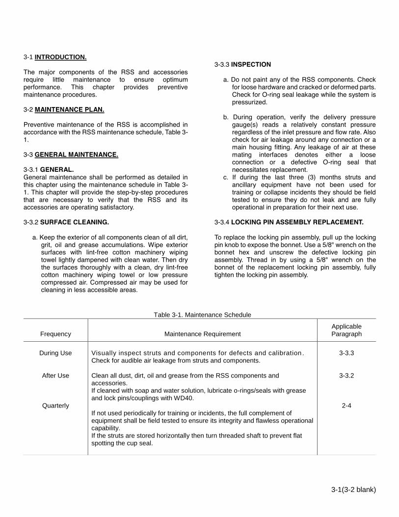
3-1 INTRODUCTION. The major components of the RSS and accessories require little maintenance to ensure optimum performance. This chapter provides preventive maintenance procedures.
3-2 MAINTENANCE PLAN.
Preventive maintenance of the RSS is accomplished in accordance with the RSS maintenance schedule, Table 3-1. 3-3 GENERAL MAINTENANCE. 3-3.1 GENERAL. General maintenance shall be performed as detailed in this chapter using the maintenance schedule in Table 3-1. This chapter will provide the step-by-step procedures that are necessary to verify that the RSS and its accessories are operating satisfactory. 3-3.2 SURFACE CLEANING.
a. Keep the exterior of all components clean of all dirt, grit, oil and grease accumulations. Wipe exterior surfaces with lint-free cotton machinery wiping towel lightly dampened with clean water. Then dry the surfaces thoroughly with a clean, dry lint-free cotton machinery wiping towel or low pressure compressed air. Compressed air may be used for cleaning in less accessible areas.
3-3.3 INSPECTION
a. Do not paint any of the RSS components. Check for loose hardware and cracked or deformed parts. Check for O-ring seal leakage while the system is pressurized.
b. During operation, verify the delivery pressure
gauge(s) reads a relatively constant pressure regardless of the inlet pressure and flow rate. Also check for air leakage around any connection or a main housing fitting. Any leakage of air at these mating interfaces denotes either a loose connection or a defective O-ring seal that necessitates replacement.
c. If during the last three (3) months struts and ancillary equipment have not been used for training or collapse incidents they should be field tested to ensure they do not leak and are fully operational in preparation for their next use.
3-3.4 LOCKING PIN ASSEMBLY REPLACEMENT. To replace the locking pin assembly, pull up the locking pin knob to expose the bonnet. Use a 5/8" wrench on the bonnet hex and unscrew the defective locking pin assembly. Thread in by using a 5/8" wrench on the bonnet of the replacement locking pin assembly, fully tighten the locking pin assembly.
Table 3-1. Maintenance Schedule
Frequency
Maintenance Requirement
Applicable Paragraph
During Use
After Use
Quarterly
Visually inspect struts and components for defects and calibration . Check for audible air leakage from struts and components. Clean all dust, dirt, oil and grease from the RSS components and accessories. If cleaned with soap and water solution, lubricate o-rings/seals with grease and lock pins/couplings with WD40. If not used periodically for training or incidents, the full complement of equipment shall be field tested to ensure its integrity and flawless operational capability. If the struts are stored horizontally then turn threaded shaft to prevent flat spotting the cup seal.
3-3.3
3-3.2
2-4


CHAPTER 4 PARTS LIST
4-1
4-1 INTRODUCTION. This chapter lists available standard and optional parts for the LockStroke Strut, AcmeThread Strut and Rigid Strut. The parts list is used to identify and locate all repair parts, including all attaching hardware supplied. The parts should be ordered by part numbers when ordered from Paratech Incorporated 1025 Lambrecht Road, Frankfort, Illinois 60423-1648. 4-2 LIST OF MAJOR COMPONENTS. The LockStroke Strut, AcmeThread Strut and Rigid Strut are comprised essentially of detail parts and contain no major components. 4-3 PARTS LIST TABLES. The LockStroke Strut, AcmeThread Strut and Rigid Strut parts are listed in Tables 4-1 through 4-4. The tables contain five columns which are described below: 4-3.1 FIGURE AND INDEX NUMBER COLUMN. This column shows the figure and index number of each part listed. Tables 4-1 through 4-4 relate to the illustrations contained in chapter 4. The index numbers which identify the individual parts are separated from the figure number by a hyphen. Index numbers run consecutively.
4-3.2 DESCRIPTION COLUMN. The DESCRIPTION column describes each part (by noun names and modifiers) in sufficient detail for clarity. Descriptions are successively intended to the right to show assembly and part relationship. 4-3.3 QUANTITY COLUMN. Quantities specified in the QUANTITY column are total number of each part required per assembly. 4-3.4 CAGE COLUMN. The assembly and parts are identified by a five digit code. These code numbers are in accordance with Federal Supply Cataloging Handbook H-4-1. A cross reference between the codes and the manufacture's is shown in Table 4-5. 4-3.5 PART NUMBER COLUMN. The part number column contains an identifying number for each part listed. Vendor’s numbers are shown where applicable. 4-4 LIST OF MANUFACTURERS. A list of all manufacture's code numbers used in the parts list shown in Table 4-5. These codes are in accordance with Federal Supply Cataloging Handbook H-4-1.

4-2
Table 4-1. LockStroke Strut Parts List
Figure and Index
Number Description Quantity
Part Number
CAGE
4-1 LOCKSTROKE STRUT 19-25 1 22-796006 3078 4-1 LOCKSTROKE STRUT 25-36 1 22-796000 3078 4-1 LOCKSTROKE STRUT 37-58 1 22-796002 3078 4-1 LOCKSTROKE STRUT 55-89 1 22-796004 3078
-1 TUBE END ADAPTER, STRUT 1 22-796067 3078 -2 NIPPLE STRUT INLET 1/8"NPSM 1 22-796065 3078 -3 O-RING 3MM X 63MM BN70 1 22-796051 3078 -4 TUBE DET. FOR 19" L.S. STRUT 1 22-796045 3078 -4 TUBE DET. FOR 25" L.S. STRUT 1 22-796046 3078 -4 TUBE DET. FOR 36" L.S. STRUT 1 22-796047 3078 -4 TUBE DET. FOR 55" L.S. STRUT 1 22-796048 3078 -5 TAPE REFL YELLOW 1" 4 22-796085 3078 -6 LABEL, SIZE FOR 796006 STRUT 1 22-LBL006 3078 -6 LABEL, SIZE FOR 796000 STRUT 1 22-LBL000 3078 -6 LABEL, SIZE FOR 796002 STRUT 1 22-LBL002 3078 -6 LABEL, SIZE FOR 796004 STRUT 1 22-LBL004 3078 -7 LABEL FOR 796006 LS STRUT 1 22-796006L 3078 -7 LABEL FOR 796000 LS STRUT 1 22-796000L 3078 -7 LABEL FOR 796002 LS STRUT 1 22-796002L 3078 -7 LABEL FOR 796004 LS STRUT 1 22-796004L 3078 -8 RELEASE RING, LOCKSTROKE 1 22-796128 3078 -9 SPRING, LOCKSTROKE STRUT 1 22-796132 3078 -10 HOUSING RING, LOCKSTROKE 1 22-796122 3078 -11 PRESSURE RING, LOCKSTROKE 1 22-796124 3078 -12 BALL 11/32 440-C SS GRADE 25 36 22-796193 3078 -13 UNLOCKING RING, LOCKSTROKE 1 22-796126 3078 -14 SEAL 2.5"O.D 2.125"I.D X 3/16 1 22-796018 3078 -15 GROOVED SHAFT FOR 19-25 STRUT 1 22-796055 3078 -15 GROOVED SHAFT FOR 25-36 STRUT 1 22-796056 3078 -15 GROOVED SHAFT FOR 36-57 STRUT 1 22-796057 3078 -15 GROOVED SHAFT FOR 55-89 STRUT 1 22-796058 3078

4-3
Table 4-2. AcmeThread Strut Parts List
Figure and
Index Number
Description Quantity Part
Number CAGE
4-2 ACMETHREAD STRUT 12-15 1 22-796212 30978 4-2 ACMETHREAD STRUT 19-25 1 22-796206 30978 4-2 ACMETHREAD STRUT 25-36 1 22-796200 30978 4-2 ACMETHREAD STRUT 37-58 1 22-796202 30978 4-2 ACMETHREAD STRUT 56-88 1 22-796204 30978
* -1 TUBE END ADAPTER, STRUT 1 22-796067 30978 * -2 NIPPLE STRUT INLET 1/8"NPSM 1 22-796065 30978 * -3 O-RING 3MM X 63MM BN70 1 22-796051 30978 -4 TUBE DET. FOR 12" ACME STRUT 1 22-796215 30978 -4 TUBE DET. FOR 19" ACME STRUT 1 22-796225 30978 -4 TUBE DET. FOR 25" ACME STRUT 1 22-796226 30978 -4 TUBE DET. FOR 37" ACME STRUT 1 22-796227 30978 -4 TUBE DET. FOR 56" ACME STRUT 1 22-796228 30978 -5 LABEL, SIZE FOR 796212 STRUT 1 22-LBL212 30978 -5 LABEL, SIZE FOR 796206 STRUT 1 22-LBL206 30978 -5 LABEL, SIZE FOR 796200 STRUT 1 22-LBL200 30978 -5 LABEL, SIZE FOR 796202 STRUT 1 22-LBL202 30978 -5 LABEL, SIZE FOR 796204 STRUT 1 22-LBL204 30978 -6 LABEL, 12” ACMETHREAD STRUT 1 22-796212L 30978 -6 LABEL, 19” ACMETHREAD STRUT 1 22-796206L 30978 -6 LABEL, 25” ACMETHREAD STRUT 1 22-796200L 30978 -6 LABEL, 37” ACMETHREAD STRUT 1 22-796202L 30978 -6 LABEL, 56” ACMETHREAD STRUT 1 22-796204L 30978 * -7 TAPE REFL YELLOW 1" 4 22-796085 30978 -8 SEAL 2.5"O.D 2.125"I.D X 3/16 1 22-796018 30978 -9 ACME SCREW DET. 12-15 STRUT 1 22-796213 30978 -9 ACME SCREW DET. 19-25 STRUT 1 22-796237 30978 -9 ACME SCREW DET. 25-36 STRUT 1 22-796234 30978 -9 ACME SCREW DET. 37-58 STRUT 1 22-796235 30978 -9 ACME SCREW DET. 56-88 STRUT 1 22-796236 30978 -10 ACME STRUT COLLAR 1 22-796240 30978 -11 O-RING AS-226 (2"X.139) BN 70 1 22-796562 30978 -12 MALE SCR END, ACME SCR, STRUT 1 22-796239 30978 -13 SET SCREW 1/4-20 X 1/2" CUP SS 1 22-895292 30978 ** -14 SHORT TUBE END, 12"STRUT 1 22-796217 30978
* PARTS EXCLUDED FOR 22-796212/ ** PARTS INCLUDE IN 22-796212 ONLY

4-4
Table 4-3. Low Clearance Supports, Extensions, Base Plates and Connectors Parts List
Figure and
Index Number
Description
Quantity
CAGE Part Number
4-3-1 RIGID STRUT 1..................................................................................... 1 30978 22-796031 -2 RIGID STRUT 3..................................................................................... 1 30978 22-796032 -3 RIGID STRUT 5..................................................................................... 1 30978 22-796033
-4 RIGID STRUT 7..................................................................................... 1 30978 22-796034
-5 STRUT EXTENSION 6.......................................................................... 1 30978 22-796017 -6 STRUT EXTENSION 12........................................................................ 1 30978 22-796012 -7 STRUT EXTENSION 24........................................................................ 1 30978 22-796024 -8 STRUT EXTENSION 36........................................................................ 1 30978 22-796036 -9 STRUT EXTENSION CONVERTER...................................................... 1 30978 22-796035
MULTI-BASE......................................................................................... 1 30978 22-796025 -10 MULTI-BASE, DETAIL.......................................................................... 1 30978 22-796027 -11 PULL ONLY LOCK PIN ASS'Y.............................................................. 1 30978 22-796072
CHAIN WEDGE FOR 3/8" CHAIN.......................................................... 1 30978 22-796130 -12 HOUSING FOR 3/8" CHAIN WEDGE.................................................... 1 30978 22-796059 -13 TWO-POSITION LOCK PIN ASS'Y........................................................ 1 30978 22-796242
V-BASE.................................................................................................. 1 30978 22-796090
-11 PULL ONLY LOCK PIN ASS'Y.............................................................. 1 30978 22-796072 -14 V-END BASE, DETAIL........................................................................... 1 30978 22-796091 -15 EYELET 5/8"UNF - DETAIL................................................................... 1 30978 22-796096
OFFSET CONE BASE........................................................................... 1 30978 22-796560 -11 PULL ONLY LOCK PIN ASS'Y.............................................................. 1 30978 22-796072 -16 HOUSING FOR OFFSET CONE BASE................................................ 1 30978 22-796561 -17 CONE FOR OFFSET CONE BASE....................................................... 1 30978 22-796563
CONTOUR BASE.................................................................................. 1 30978 22-796270 -11 PULL ONLY LOCK PIN ASS'Y.............................................................. 1 30978 22-796072 -18 CONTOUR BASE, DETAIL................................................................... 1 30978 22-796271
RUBBER BASE 4"................................................................................. 1 30978 22-796190 -11 PULL ONLY LOCK PIN ASS'Y.............................................................. 1 30978 22-796072 -15 EYELET 5/8"UNF - DETAIL................................................................... 1 30978 22-796096 -19 HUB, STRUT ENDS............................................................................... 1 30978 22-796064 -20 RUBBER FOOT MOLDING, STRUT..................................................... 1 30978 22-796192 -21 3/8 LOCK WASHER S.S....................................................................... 1 30978 22-796088 -22 SCR 3/8-16 HEX HD 7/8"LG S.S.......................................................... 1 30978 22-796082
RIGID BASE 6....................................................................................... 1 30978 22-796070 -11 PULL ONLY LOCK PIN ASS'Y.............................................................. 1 30978 22-796072 -15 EYELET 5/8"UNF - DETAIL................................................................... 1 30978 22-796096 -19 HUB, STRUT ENDS............................................................................... 1 30978 22-796064 -22 SCR 3/8-16 HEX HD 7/8"LG S.S........................................................... 1 30978 22-796082 -23 6"SQ STD PRESSURE PLATE............................................................. 1 30978 22-796061
SWIVEL BASE 6.................................................................................... 1 30978 22-796060 -11 PULL ONLY LOCK PIN ASS'Y.............................................................. 1 30978 22-796072 -15 EYELET 5/8"UNF - DETAIL................................................................... 1 30978 22-796096 -24 HUB, FOR STRUT SWIVEL BASE....................................................... 1 30978 22-796066 -25 6"SQ SWIVEL PRESSURE PLATE....................................................... 1 30978 22-796062 -26 SPHERICAL WASHER, STRUT............................................................ 1 30978 22-796074 -27 DISC SPRING 20X10.2X1 SS............................................................... 1 30978 22-670570 -28 3/8-16 HEX NYL LOCKNUT SS............................................................. 1 30978 22-796086 -29 SCR 3/8-16 HEX HD 1.5"LG ULTRA..................................................... 1 30978 22-796084

4-5
Table 4-3. Low Clearance Supports, Extensions, Base Plates and Connectors Parts List Figure and Index Number
Description
Quantity
CAGE Part Number
HINGED BASE 6.................................................................................... 1 30978 22-796140 4-3-11 PULL ONLY LOCK PIN ASS'Y.............................................................. 1 30978 22-796072 -15 EYELET 5/8"UNF - DETAIL................................................................... 1 30978 22-796096 -21 3/8 LOCK WASHER S.S....................................................................... 1 30978 22-796088 -22 SCR 3/8-16 HEX HD 7/8"LG S.S. ......................................................... 1 30978 22-796082 -23 6"SQ STD PRESSURE PLATE............................................................. 1 30978 22-796061 -30 CLEVIS, MALE END.............................................................................. 1 30978 22-796142 -31 CLEVIS FEMALE, HINGED BASE........................................................ 1 30978 22-796144 -32 RET RING EXT. 3/4"SHAFT H.SECT.................................................... 2 30978 22-796148 -33 PIN, CLEVIS, STRUT HINGE BASE..................................................... 1 30978 22-796146
HINGED BASE W/ANCHOR RING 6..................................................... 1 30978 22-796150 -11 PULL ONLY LOCK PIN ASS'Y.............................................................. 1 30978 22-796072 -21 3/8 LOCK WASHER S.S. ...................................................................... 1 30978 22-796088 -22 SCR 3/8-16 HEX HD 7/8"LG S.S. ......................................................... 1 30978 22-796082 -23 6"SQ STD PRESSURE PLATE............................................................. 1 30978 22-796130 -31 CLEVIS FEMALE, HINGED BASE........................................................ 1 30978 22-796144 -34 CLEVIS, MALE END.............................................................................. 1 30978 22-796142A -35 ANCHOR RING, FINISHED.................................................................. 1 30978 22-796154 -36 1/2-13 HEX NUT S.S. ........................................................................... 2 30978 22-796434 -37 1/2" REG. SPRNG LOCK WASHER SS................................................ 2 30978 22-796438 -38 WASHER 1/2 TYPE B SER N SS.......................................................... 2 30978 22-796435 -39 PIN FOR ANCHOR RING...................................................................... 1 30978 22-796145
RIGID BASE 12...................................................................................... 1 30978 22-796180A -11 PULL ONLY LOCK PIN ASS'Y.............................................................. 1 30978 22-796072 -40 12" PRESSURE PLATE, DETAIL.......................................................... 1 30978 22-796063 -41 SCR 3/8-16 X 1.125" GR 8 ZINC........................................................... 1 30978 22-670549 -42 3/8"PLAIN "A" WASHR SER. N, SS...................................................... 1 30978 22-796099 -43 HUB FOR 12"PLAT................................................................................ 1 30978 22-796064B -44 HELI-COIL 3/8-16 X .375 SS................................................................. 1 30978 22-550054 -45 NUT 3/8 SPINN GRIP FL L-NUT SS..................................................... 1 30978 22-670538
SWIVEL BASE 12.................................................................................. 1 30978 22-796180B -11 PULL ONLY LOCK PIN ASS'Y.............................................................. 1 30978 22-796072 -15 EYELET 5/8"UNF - DETAIL................................................................... 1 30978 22-796096 -24 HUB, FOR STRUT SWIVEL BASE....................................................... 1 30978 22-796066 -26 SPHERICAL WASHER, STRUT............................................................ 1 30978 22-796074 -27 DISC SPRING 20X10.2X1 SS............................................................... 1 30978 22-670570 -40 12" PRESSURE PLATE, DETAIL.......................................................... 1 30978 22-796063 -44 HELI-COIL 3/8-16 X .375 SS................................................................. 1 30978 22-550054 -45 NUT 3/8 SPINN GRIP FL L-NUT SS..................................................... 1 30978 22-670538 -46 SCR 3/8-16 HEX HD 1.75"LG GR 8...................................................... 1 30978 22-670550 -47 ADAPTER FOR SWIVEL BASE PLATE................................................ 1 30978 22-796184
HINGED BASE 12.................................................................................. 1 30978 22-796180R -11 PULL ONLY LOCK PIN ASS'Y.............................................................. 1 30978 22-796072 -31 CLEVIS FEMALE, HINGED BASE........................................................ 1 30978 22-796144 -34 CLEVIS, MALE END.............................................................................. 2 30978 22-796142A -36 1/2-13 HEX NUT S.S. ........................................................................... 2 30978 22-796434 -37 1/2" REG. SPRNG LOCK WASHER SS................................................ 2 30978 22-796438 -38 WASHER 1/2 TYPE B SER N SS.......................................................... 1 30978 22-796435 -40 12" PRESSURE PLATE, DETAIL.......................................................... 1 30978 22-796063 -41 SCR 3/8-16 X 1.125" GR 8 ZINC........................................................... 1 30978 22-670549 -42 3/8"PLAIN "A" WASHR SER. N, SS...................................................... 1 30978 22-796099 -44 HELI-COIL 3/8-16 X .375 SS................................................................. 1 30978 22-550054 -45 NUT 3/8 SPINN GRIP FL L-NUT SS..................................................... 1 30978 22-670538 -46 PIN 3/4" WITH 1/2"THREADS............................................................... 1 30978 22-796147

4-6
Table 4-3. Low Clearance Supports, Extensions, Base Plates and Connectors Parts List Figure and Index Number
Description
Quantity
CAGE Part Number
HINGED BASE W/ANCHOR RING 12................................................... 1 30978 22-796180C 4-3-11 PULL ONLY LOCK PIN ASS'Y.............................................................. 1 30978 22-796072 -31 CLEVIS FEMALE, HINGED BASE........................................................ 1 30978 22-796144 -34 CLEVIS, MALE END.............................................................................. 1 30978 22-796142A -35 ANCHOR RING, FINISHED................................................................... 1 30978 22-796154 -36 1/2-13 HEX NUT S.S. ............................................................................ 2 30978 22-796434 -37 1/2" REG. SPRNG LOCK WASHER SS................................................ 2 30978 22-796438 -38 WASHER 1/2 TYPE B SER N SS.......................................................... 2 30978 22-796435 -39 PIN FOR ANCHOR RING...................................................................... 1 30978 22-796145 -40 12" PRESSURE PLATE, DETAIL.......................................................... 1 30978 22-796063 -41 SCR 3/8-16 X 1.125" GR 8 ZINC........................................................... 1 30978 22-670549 -42 3/8"PLAIN "A" WASHR SER. N, SS...................................................... 1 30978 22-796099 -44 HELI-COIL 3/8-16 X .375 SS................................................................. 1 30978 22-550054 -45 NUT 3/8 SPINN GRIP FL L-NUT SS..................................................... 1 30978 22-670538 ANGLE BASE 3" X 4"............................................................................ 1 30978 22-796092 -11 PULL ONLY LOCK PIN ASS'Y.............................................................. 1 30978 22-796072 -15 EYELET 5/8"UNF - DETAIL................................................................... 1 30978 22-796096 -19 HUB, STRUT ENDS.............................................................................. 1 30978 22-796064 -45 NUT 3/8 SPINN GRIP FL L-NUT SS..................................................... 1 30978 22-670538 -47 ANGLE, T-PLATE, STRUT.................................................................... 1 30978 22-796097 -48 SCR 3/8 FLAT HD SOC 1.125" SS........................................................ 1 30978 22-796083 CHANNEL BASE 4" X 4"....................................................................... 1 30978 22-796134 -11 PULL ONLY LOCK PIN ASS'Y.............................................................. 1 30978 22-796072 -15 EYELET 5/8"UNF - DETAIL................................................................... 1 30978 22-796096 -19 HUB, STRUT ENDS.............................................................................. 1 30978 22-796064 -45 NUT 3/8 SPINN GRIP FL L-NUT SS..................................................... 1 30978 22-670538 -49 SPRING PIN 3/16 X 9/16 SS................................................................. 1 30978 22-670556 -50 3/8-16 FLAT SOC HD 1"LG SS............................................................. 1 30978 22-796531 -51 CHANNEL DET FOR 4X4" TIMBER...................................................... 1 30978 22-796135 CHANNEL BASE 6" X 6"....................................................................... 1 30978 22-796136 -11 PULL ONLY LOCK PIN ASS'Y.............................................................. 1 30978 22-796072 -15 EYELET 5/8"UNF - DETAIL................................................................... 1 30978 22-796096 -19 HUB, STRUT ENDS.............................................................................. 1 30978 22-796064 -45 NUT 3/8 SPINN GRIP FL L-NUT SS..................................................... 1 30978 22-670538 -49 SPRING PIN 3/16 X 9/16 SS................................................................. 1 30978 22-670556 -50 3/8-16 FLAT SOC HD 1"LG SS............................................................. 1 30978 22-796531 -52 CHANNEL DET FOR 6X6" TIMBER...................................................... 1 30978 22-796137 45° BASE............................................................................................... 1 30978 22-796690 -11 PULL ONLY LOCK PIN ASS'Y.............................................................. 1 30978 22-796072 -34 CLEVIS, MALE END.............................................................................. 1 30978 22-796142A -36 1/2-13 HEX NUT S.S. ........................................................................... 2 30978 22-796434 -37 1/2" REG. SPRNG LOCK WASHER SS................................................ 2 30978 22-796438 -38 WASHER 1/2 TYPE B SER N SS.......................................................... 2 30978 22-796435 -46 PIN 3/4" WITH 1/2"THREADS............................................................... 1 30978 22-796147 -73 45° BASE WELDMENT......................................................................... 1 30978 22-796694 -74 FEMALE CLEVIS W/(4)THD HOLES.................................................... 1 30978 22-796144B -75 SCR 5/16-18X 1.25 HEXHD SS........................................................... 4 30978 22-670520 -76 LOCK WASHER 5/16, REGULAR, SS.................................................. 4 30978 22-670574

4-7
Table 4-3. Low Clearance Supports, Extensions, Base Plates and Connectors Parts List
Figure and Index Number
Description Quantity CAGE Part Number
ANGLED RUBBER BASE (ESU)............................................................ 1 30978 22-796266 4-3-15 EYELET 5/8"UNF - DETAIL................................................................... 1 30978 22-796096
-54 TWO-POSITION LOCK PIN ASS'Y...................................................... 1 30978 22-796242 -55 ANGLE RUBBER BASE W/RUBBER.................................................... 1 30978 22-796266R
ELEVATOR SUPPORT LEFT ARM....................................................... 1 30978 22-796260L -54 TWO-POSITION LOCK PIN ASS'Y....................................................... 1 30978 22-796242 -56 ARM ELEVATOR SUPPORT, DETAIL.................................................. 1 30978 22-796264 -57 SCR 1/2-13 X 2.5"SOC. HD ZINC PL.................................................... 4 30978 22-796433 -58 HOUSING, ELEVATOR SUPPORT ARM.............................................. 1 30978 22-796262
ELEVATOR SUPPORT RIGHT ARM.................................................... 1 30978 22-796260R -54 TWO-POSITION LOCK PIN ASS'Y....................................................... 1 30978 22-796242 -56 ARM ELEVATOR SUPPORT, DETAIL.................................................. 1 30978 22-796264 -57 SCR 1/2-13 X 2.5"SOC. HD ZINC PL.................................................... 4 30978 22-796433 -58 HOUSING, ELEVATOR SUPPORT ARM.............................................. 1 30978 22-796262
SPRING LOADED CONNECTOR......................................................... 1 30978 22-796170 -11 PULL ONLY LOCK PIN ASS'Y.............................................................. 1 30978 22-796072 -59 FEM END, SPRING CONN., STRUT..................................................... 1 30978 22-796174 -60 SPRING 1.5X2 HEAVY LOAD RED...................................................... 1 30978 22-670538 -61 MALE END, SPRING CONN., STRUT.................................................. 1 30978 22-796178 -62 SCREW, SPRING CONN. STRUT........................................................ 1 30978 22-670556
ADJUSTABLE THREADED CONNECTOR........................................... 1 30978 22-796160 -11 PULL ONLY LOCK PIN ASS'Y.............................................................. 1 30978 22-796072 -63 FEM. END, ADJUST. CONN. STRUT................................................... 1 30978 22-796162 -64 SET SCREW 1/4-20 X 1/2" CUP SS..................................................... 1 30978 22-895292 -65 MALE END, ADJ CONN, STRUT.......................................................... 1 30978 22-796164
WALER STOP BLOCK.......................................................................... 1 30978 22-796285 -66 STRIKER FO RAKER LATCH BASE..................................................... 1 30978 22-796254 -67 LEVER FOR RAKER LATCH BASE...................................................... 1 30978 22-796253 -68 SPRING C0480-045-1000S................................................................... 1 30978 22-796256 -69 WALER STOP BLOCK, FINISHED........................................................ 1 30978 22-796286 -70 PIN FOR STOP BLOCK......................................................................... 1 30978 22-796289
WALER CONNECTOR.......................................................................... 1 30978 22-796287 -77 WALER CONNECTOR, MACH. DETAIL.............................................. 1 30978 22-796288 -66 STRIKER FO RAKER LATCH BASE................................................... 1 30978 22-796254 -67 LEVER FOR RAKER LATCH BASE.................................................... 1 30978 22-796253 -68 SPRING C0480-045-1000S................................................................. 1 30978 22-796256
CHANNEL BASE METRIC 4.3" X 6"...................................................... 1 30978 22-796131 -11 PULL ONLY LOCK PIN ASS'Y.............................................................. 1 30978 22-796072 -15 EYELET 5/8"UNF - DETAIL................................................................... 1 30978 22-796096 -19 HUB, STRUT ENDS.............................................................................. 1 30978 22-796064 -45 NUT 3/8 SPINN GRIP FL L-NUT SS..................................................... 1 30978 22-670538 -49 SPRING PIN 3/16 X 9/16 SS................................................................. 1 30978 22-670556 -50 3/8-16 FLAT SOC HD 1"LG SS............................................................. 1 30978 22-796531 -71 CHANNEL FOR 4.25"BASE.................................................................. 1 30978 22-796138
CHANNEL BASE METRIC 6.3" X 7"..................................................... 1 30978 22-796133 -11 PULL ONLY LOCK PIN ASS'Y.............................................................. 1 30978 22-796072 -15 EYELET 5/8"UNF - DETAIL................................................................... 1 30978 22-796096 -19 HUB, STRUT ENDS.............................................................................. 1 30978 22-796064 -45 NUT 3/8 SPINN GRIP FL L-NUT SS..................................................... 1 30978 22-670538 -49 SPRING PIN 3/16 X 9/16 SS................................................................. 1 30978 22-670556 -50 3/8-16 FLAT SOC HD 1"LG SS............................................................. 1 30978 22-796531 -72 CHANNEL FOR 6.25"BASE.................................................................. 1 30978 22-796139

4-8
Table 4-3. Low Clearance Supports, Extensions, Base Plates and Connectors Parts List

4-9
Table 4-3. Low Clearance Supports, Extensions, Base Plates and Connectors Parts List

4-10
Table 4-4. Code to Name List
CAGE Manufacturer's or Vendor's Name and Address
30978 Paratech Incorporated, 1025 Lambrecht Road, Frankfort, Illinois 60423


