OPERATION AND MAINTENANCE MANUAL - Altorfer AND MAINTENANCE MANUAL . ... Scheduled Preventive...
18
OPERATION AND MAINTENANCE MANUAL Alternative Fueled Engines A product by Power Solutions International, Inc Wood Dale, IL 56100000E Operation & Maintenance Manual 1
-
Upload
nguyenkhue -
Category
Documents
-
view
228 -
download
2
Transcript of OPERATION AND MAINTENANCE MANUAL - Altorfer AND MAINTENANCE MANUAL . ... Scheduled Preventive...
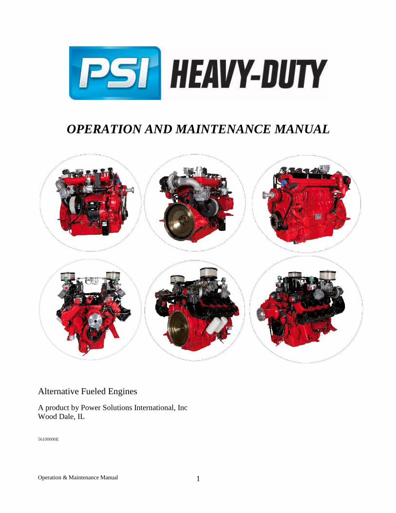
OPERATION AND MAINTENANCE MANUAL
Alternative Fueled Engines
A product by Power Solutions International, Inc Wood Dale, IL
56100000E
Operation & Maintenance Manual
1
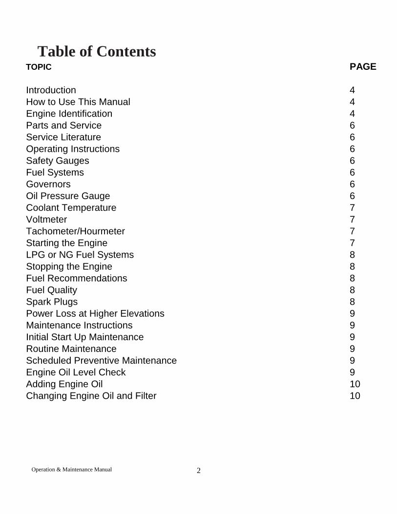
TOPIC PAGE
Introduction 4How to Use This Manual 4Engine Identification 4Parts and Service 6Service Literature 6Operating Instructions 6Safety Gauges 6Fuel Systems 6Governors 6Oil Pressure Gauge 6Coolant Temperature 7Voltmeter 7Tachometer/Hourmeter 7Starting the Engine 7LPG or NG Fuel Systems 8Stopping the Engine 8Fuel Recommendations 8Fuel Quality 8Spark Plugs 8Power Loss at Higher Elevations 9Maintenance Instructions 9Initial Start Up Maintenance 9Routine Maintenance 9Scheduled Preventive Maintenance 9Engine Oil Level Check 9Adding Engine Oil 10Changing Engine Oil and Filter 10
Table of Contents
Operation & Maintenance Manual
2
TOPIC PAGE
Engine Oil Quality 10Engine Oil Recommendation 11Oil Filter 11Engine Air Cleaner 11Safety Element 11Cooling System 12Coolant Level 12Radiator 12Fan Belts 13Serpentine Belt 13V-Type Belt 13Fuel Filter 13Fuel Shut Off 13Ignition Systems 14Types of Ignition Systems 14Ignition Timing 14Spark Plugs 14Storage 15One to Six Months 15Extended Periods 15Removing the Engine From Storage 15Maintenance Schedule 16General Specifications 17General Specifications 18
No part of this publication may be reproduced without written permission from PSI Heavy-Duty At the time of publication, all of the information included in this publication is accurate to the best of our knowledge. PSI Heavy-Duty cannot be responsible for information that has changed after this book was published.
Operation & Maintenance Manual
3
Introduction PSI Heavy-Duty is pleased that you have selected our engine for your requirements. PSI Heavy-Duty takes great pride in our tradition of quality products produced from our line of industrial alternative fuel engines.
Prior to starting the engine at your facility, certain checks should be made. Please read the Initial Start-Up inspection requirements in the Maintenance Section of this manual. If you have further questions please contact your PSI account representative or Customer Support Engineer.
How to Use this Manual
This manual contains instructions on the safe operation and preventive maintenance of your PSI Heavy-Duty industrial engine. We urge you to read this manual prior to start up or operation of the engine.
The Table of Contents permits you to quickly open the manual to any section.
PSI Heavy-Duty are built with a variety of standard and/or optional components to suit a broad range of customer requirements. This manual does not identify equipment as standard or optional. All the equipment described in this manual may not be found on your engine or power unit.
Please pay special attention to the NOTES, CAUTIONS, and WARNINGS. WARNINGS remind you to be careful in areas where carelessness can cause personal injury. CAUTIONS are given to prevent you from error that could cause damage to the equipment. NOTES give you added information designed to help you.
The descriptions and specifications contained in this manual were in effect at the time of publication. PSI Heavy-Duty reserves the right to discontinue models at any time, or to change specifications or design without notice and without incurring obligation.
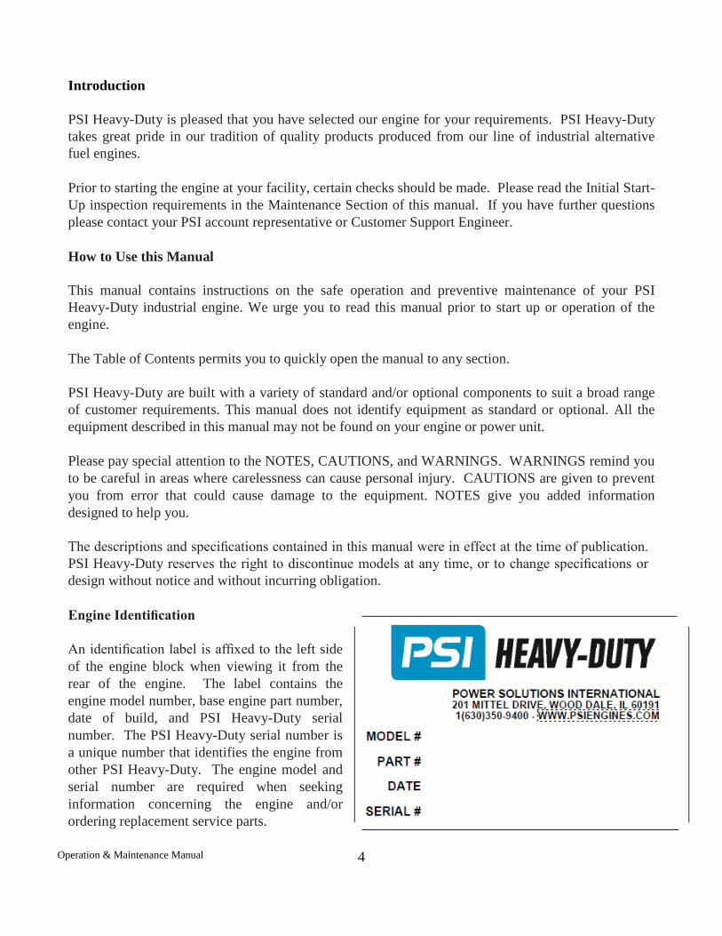
Engine Identification
An identification label is affixed to the left side of the engine block when viewing it from the rear of the engine. The label contains the engine model number, base engine part number, date of build, and PSI Heavy-Duty serial number. The PSI Heavy-Duty serial number is a unique number that identifies the engine from other PSI Heavy-Duty. The engine model and serial number are required when seeking information concerning the engine and/or ordering replacement service parts.
Operation & Maintenance Manual
4
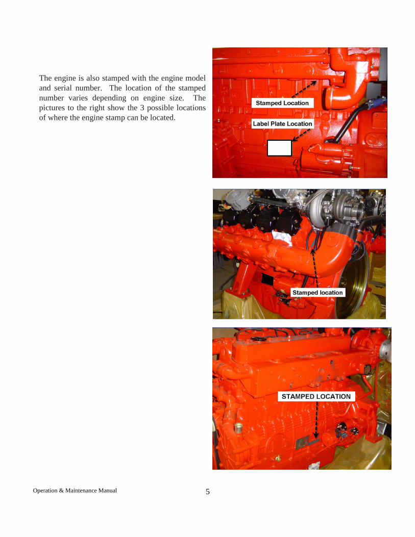
The engine is also stamped with the engine model and serial number. The location of the stamped number varies depending on engine size. The pictures to the right show the 3 possible locations of where the engine stamp can be located.
Operation & Maintenance Manual
5
Parts and Service
Replacement parts can be obtained from PSI Heavy-Duty by calling the Aftermarket Parts Department at 888-331-5769. The engine model and serial number will be required when seeking information and/or ordering parts.
Service and technical support for PSI Heavy-Duty can be obtained by contacting the Service Department at 888-331-5764 or via email at [email protected].
Service Literature
Additional operator manuals and service manuals for specific PSI Heavy-Duty can be obtained by contacting the Parts or Service Department at 888-331-5769.
Operating Instructions
Fuel Systems
The fuel system installed on your engine operates with an Integrated Electronic Pressure Regulator (IEPR) and a diaphragm style variable venturi mixer. The IEPR will regulate the fuel pressure being delivered to the mixer; these parts are not adjustable and should not be tampered with. Proper inlet fuel pressure is critical to the proper operation of the fuel system and engine; you should the review the pressure, volume, and BTU recommendations prior to commissioning the engine.
Governors
PSI Heavy-Duty have an isochronous governor installed. The governor controls the movement of the throttle via a 0-12 volt signal and a ground provided by the Engine Control Module. The throttle allows the correct amount of air to enter the engine; this movement is monitored by using 2 throttle position sensors located internal to the throttle. The ECM monitors various engine sensors to determine what the correct throttle position should be.
Oil Pressure Reading
The oil pressure reading shows the engine lubrication system pressure in pounds per square inch (psi) and should be checked frequently to ensure that the system is functioning correctly. Should the pressure fluctuate or drop, stop the engine and find the cause. Do not operate the engine at lower than normal oil pressure (see maintenance schedule for minimum engine oil pressure).
Operation & Maintenance Manual
6
CAUTION: Do not continue to operate your engine below the normal operating range. Severe engine damage could occur.
Coolant Temperature
The coolant temperature reading will indicate overheating which may arise from low coolant level, plugged radiator, loose fan belt or faulty thermostat. Coolant level should be checked daily.
CAUTION: If the engine continues to overheat, have the cooling system checked and serviced.
Voltage Reading
The PSI Heavy-Duty product operates on a 24 volt electrical system. The voltage reading indicates the battery charging voltage. If the meter consistently indicates less than 26 volts or more than 31 volts under normal operating conditions, you should have the engine electrical system checked by a qualified service technician. Tachometer/Hourmeter
The tachometer indicates the engine speed in hundreds of revolutions per minute (rpm). It serves, as a guide to insure that engine speed is set correctly.
The hour meter records the hours of operation and is used to determine when periodic maintenance is required.
Starting the Engine
WARNING: All internal combustion engines give off various fumes and gases while running. Do not start or run the engine in a closed or poorly ventilated building where exhaust gases can accumulate. Avoid breathing these gases as they may contain poisonous carbon monoxide, which can endanger your health or life if inhaled steadily for even a few minutes.
If the engine is equipped with a manual clutch it must be disengaged prior to starting the engine. Starting the engine with the clutch engaged imposes unnecessary strain on the battery, starter, and driven components.
CAUTION: If the engine stalls or falters during starting, wait 3 to 4 seconds before re-engaging the starter. This will prevent possible damage to the starter and the engine. DO NOT operate the starter for periods longer than 30 seconds at a time. An interval of at least 1-minute should be observed between cranking periods to protect the starter from overheating.
Operation & Maintenance Manual
7
NG Fuel Systems
Turn on the gas supply to the engine. Turn the ignition key to the START position. After the engine starts return the key to the ON position.
Stopping the Engine
Return the engine to idle speed. If the machine is equipped with a clutch, move the clutch lever to the disengaged position. Run engine for a few minutes at idle to allow the coolant and oil systems to cool down before turning the ignition switch to the OFF position.
WARNING: Avoid injury when checking a Hot Engine. Allow the engine to cool down before removing the radiator cap.
CAUTION: Before restarting the engine ensure that both the coolant system and the engine oil level have been checked and re-filled if necessary. Fuel Recommendations
Fuel Quality
PSI Heavy-Duty are designed to operate on pipeline quality natural gas with a heat value of 1050 BTU or higher. LPG engines and fuel systems are designed to operate on HD-5 or HD-10 specification LPG fuel. Fuel other than HD-5 or HD-10 may cause harm to the engine’s emission control system and a warranty claim may be denied on this basis if operators can readily find the proper fuel. Use of any other fuel may result in your engine no longer operating in compliance with CARB or EPA emissions requirements.
Spark plugs
Always use the recommended spark plugs for your engine. Hotter or colder plugs, or similar plugs that are not exact equivalents to the recommended plugs, can cause permanent engine damage, reduce the engines useful life, and cause many other problems such as hard starting, spark knock and run-on. Installing new spark plugs regularly is one of the best ways to keep your engine at peak performance.
Operation & Maintenance Manual
8
Power Loss at Higher Elevations & Temperatures
All engines will experience power loss when operated at elevations above sea level or at temperatures above 77 degrees Fahrenheit.
A derate of -1% for every 10°F over 77°F air inlet temperature must be applied. A derate of -3% for every 1000 feet above 328 feet above sea level must be applied
MAINTENANCE INSTRUCTIONS
Initial Start Up Maintenance
The initial start-up checks must be made before putting the engine into service. Please refer to the Maintenance Schedule and perform the initial start-up operations in the sequence shown in column 1.
Routine Maintenance
Routine maintenance provides the best solution for making sure that the engine is ready when you are. The following are some routine service points:
• Make daily checks of the engine oil and coolant levels • Repair any oil or coolant leaks immediately • Check battery condition and cables frequently • Keep the engine air filter clean • Monitor engine coolant temperature • Monitor engine oil pressure • Check voltmeter and charging system Scheduled Preventive Maintenance
Refer to the Maintenance Schedule to ensure that all of the maintenance items listed are checked and replaced as recommended at the hours shown.
Engine Oil Level Check
The engine oil level should be checked daily. It is recommended that the oil be checked just before the engine is started for the first time for that day. The oil level should be between the ‘Add’ and the ‘Full’ marks on the dipstick.
CAUTION: Do not operate the engine with the oil level below the bottom or ‘Add’ mark on the
Operation & Maintenance Manual
9
dipstick, or above the top or ‘Full’ mark on the dipstick.
Adding Engine Oil
It is normal to add some oil in the period of time between oil changes. The amount will vary with the severity of operation. When adding or replacing engine oil, be sure the oil meets or exceeds the recommended specification.
Changing Engine Oil and Filter
The first oil and filter change should occur after 50 hours of operation.
After the first engine oil and filter change, the engine oil and filter must be changed every 200 hours or every 3 months whichever occurs first. Under normal operating conditions, you do not need to change them more often if you use oil and filters of the recommended quality.
The oil and filter should be changed more often if the engine is operating in dusty or extremely dirty areas, or during cold weather. No oil additives or break-in oil change is required.
Engine Oil Quality
To achieve proper engine performance and durability, it is important that you use only engine lubricating oils of the correct quality in your engine. Proper quality oils also provide maximum efficiency for crankcase ventilation systems, which reduces pollution.
The oil should be rated API “CD/CF” rating or higher and the ash content should be below 0.5%.
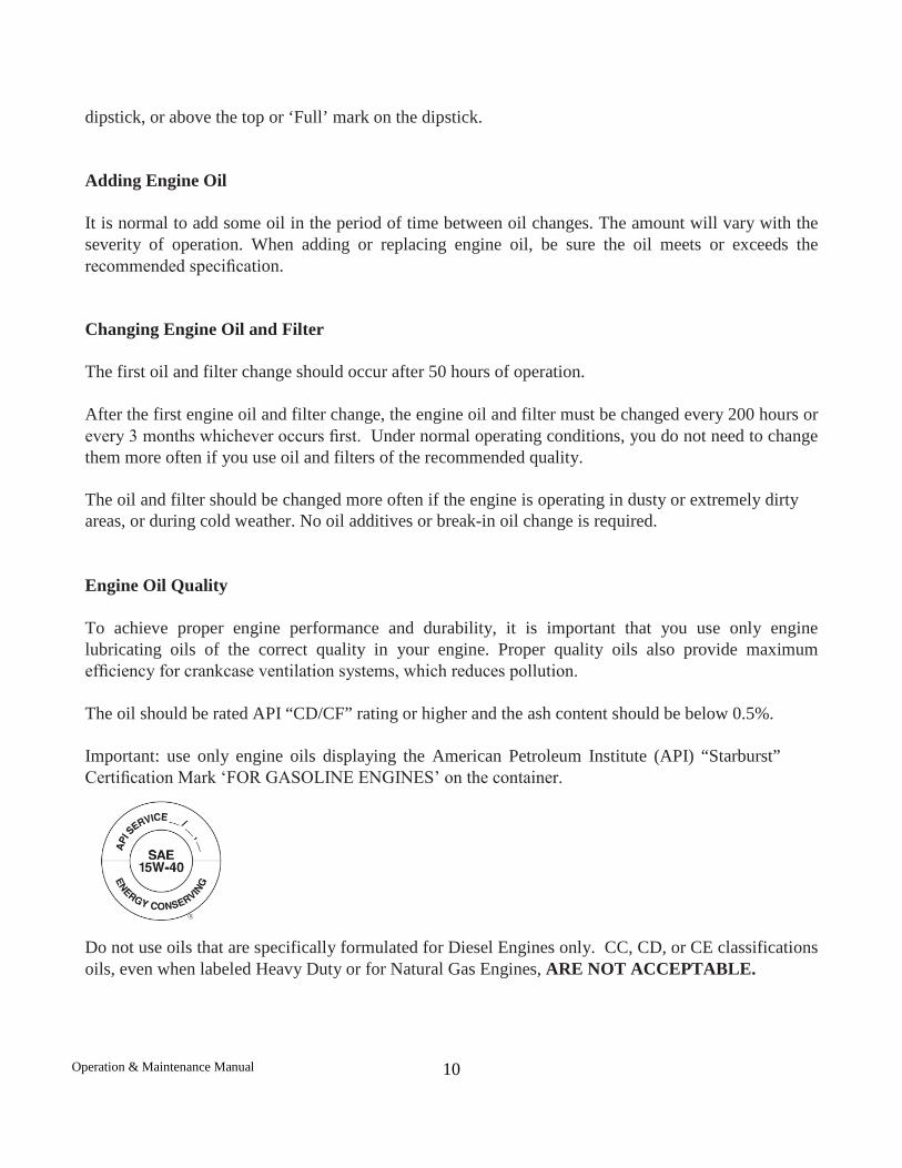
Important: use only engine oils displaying the American Petroleum Institute (API) “Starburst” Certification Mark ‘FOR GASOLINE ENGINES’ on the container.
Do not use oils that are specifically formulated for Diesel Engines only. CC, CD, or CE classifications oils, even when labeled Heavy Duty or for Natural Gas Engines, ARE NOT ACCEPTABLE.
Operation & Maintenance Manual
10
Engine Oil Recommendation
Multi-viscosity oil is recommended. SAE 15W-40 is recommended for your PSI Heavy-Duty industrial product. Synthetic oils are not recommended for industrial or stationary engines. The ash content should be less than 0.5% ash content, the use of a median ash content will void the catalyst warranty.
Oil Filter
The filter protects your engine from harmful, abrasive, or sludge particles without blocking the flow of oil to vital engine parts.
To replace the filter, use a proper filter wrench to remove the filter.
Clean the filter mounting base and lightly coat the gasket surface of the new filter with engine oil. Hand tighten the filter until the gasket contacts the base, then tighten another ½ turn. Fill the engine with the correct amount of oil and run the engine. Verify oil pressure is okay and check for oil leaks at the drain plug and oil filter gasket. Tighten as necessary to stop any oil leakage noted.
Engine Air Cleaner
The engine air cleaner filters air entering the engine intake system and acts as a silencer and flame arrester when assembled to the intake system. Air that contains dirt and grit produces an abrasive fuel mixture and can cause severe damage to the cylinder walls and piston rings. Damage to the cylinder walls and piston rings will cause high oil consumption and shorten engine life. A restricted or dirty air cleaner will also cause a rich fuel mixture. Thus, it is extremely important that the air cleaner be serviced properly at the recommended intervals. PSI Heavy-Duty recommends using only UL recognized filter elements to ensure backfire suppression. CAUTION: Service the air cleaner more frequently under severe dusty or dirty conditions.
Remove the primary air cleaner element from the air cleaner assembly and inspect the element for foreign material restrictions or signs of excessive wear or damage. Replace the element if necessary. Remove all dust and foreign matter from the air cleaner housing. Reinstall the air cleaner element. Reinstall the air cleaner cup, and securely fasten the retaining clips.
Safety Element
If your engine is equipped with an air cleaner which utilizes a safety element, ensure that the element is properly in place before installing the primary element.
Change the safety element annually.
Operation & Maintenance Manual
11
Cooling System
Coolant Level
Check the coolant level of the radiator daily and only when the engine is cool. Do this just prior to starting the engine for the first time each day.
Maintain the coolant level at ¾ to 1½ inches below the filler neck seat of the radiator when the coolant is cold. When ever coolant level checks are made inspect the condition of the radiator cap rubber seal. Make sure it is clean and free of any dirt particles which would keep it from seating on the filler neck seat. Rinse off with clean water if necessary. Also make sure that the filler neck seat is free of any dirt particles.
WARNING: Never remove the radiator cap under any conditions while the engine is operating or hot. Failure to follow these instructions could result in damage to the cooling system, engine, or cause personal injury. To avoid having scalding hot coolant or steam blow out of the radiator, use extreme caution when removing the radiator cap from a hot radiator. If possible, wait until the engine has cooled, then wrap a thick cloth around the radiator cap and turn slowly to the first stop. Step back while the pressure is released from the cooling system. When all the pressure has been released, press down on the cap and remove it slowly.
DO NOT add coolant to any engine that has become overheated until the engine cools. Adding coolant to an extremely hot engine can result in a cracked block or cylinder head.
The engine manufacturer recommends the cooling system be filled with a 50/50 mixture of antifreeze and water. The use of DexCool “Long Life” type coolant is required. This antifreeze is typically a bright orange in color and should meet the requirements issued by PSI Heavy-Duty. Coolant should have a minimum boiling point of 300F (149c) and a freezing point no higher than -34F (-37c). Plain water may be used in an emergency (except in freezing temperatures), but replace it with the specified coolant as quickly as possible to avoid damage to the system.
Radiator
Inspect the exterior of the radiator for obstructions. Remove all bugs, dirt or foreign material with a soft brush or cloth. Use care to avoid damaging the core fins. If available, use low pressure compressed air or a stream of water in the opposite direction of the normal air flow. Check all hoses and connections for leaks. If any of the hoses are cracked, frayed, or feel spongy, they must be replaced.
Operation & Maintenance Manual
12
Fan Belts
The water pump is belt driven. The same belt may also drive the fan and/or the alternator. The drive belts should be properly adjusted at all times. A loose belt can cause improper alternator, fan and water pump operation, in addition to overheating.
Serpentine Belt
Some PSI Heavy-Duty engines utilize serpentine belts on the front of the engine. This type of belt system incorporates a belt tensioning device which keeps the belt at the proper tension.
This belt should be checked routinely for cracks or ‘checking’ on the groove side of the belt. If cracks or ‘checking’ are apparent the belt must be changed.
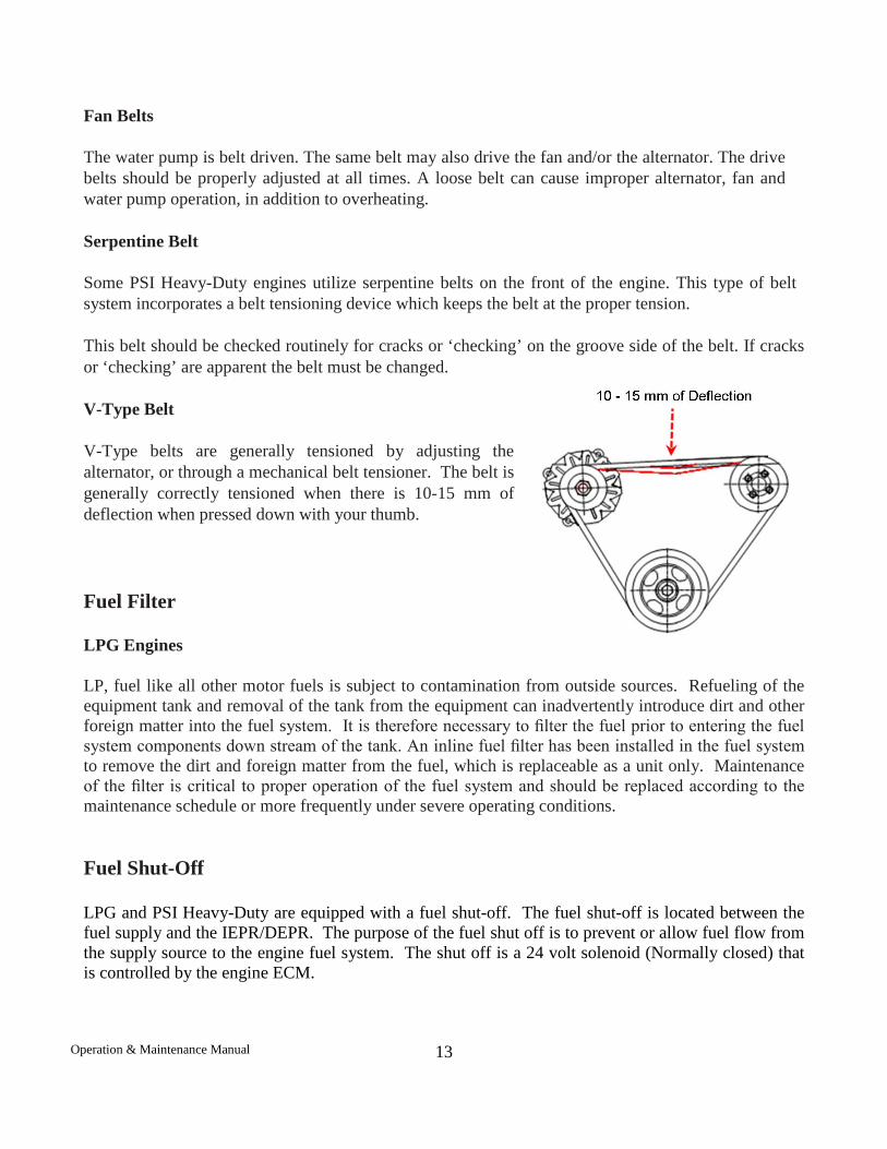
V-Type Belt
V-Type belts are generally tensioned by adjusting the alternator, or through a mechanical belt tensioner. The belt is generally correctly tensioned when there is 10-15 mm of deflection when pressed down with your thumb.
Fuel Filter
LPG Engines
LP, fuel like all other motor fuels is subject to contamination from outside sources. Refueling of the equipment tank and removal of the tank from the equipment can inadvertently introduce dirt and other foreign matter into the fuel system. It is therefore necessary to filter the fuel prior to entering the fuel system components down stream of the tank. An inline fuel filter has been installed in the fuel system to remove the dirt and foreign matter from the fuel, which is replaceable as a unit only. Maintenance of the filter is critical to proper operation of the fuel system and should be replaced according to the maintenance schedule or more frequently under severe operating conditions. Fuel Shut-Off LPG and PSI Heavy-Duty are equipped with a fuel shut-off. The fuel shut-off is located between the fuel supply and the IEPR/DEPR. The purpose of the fuel shut off is to prevent or allow fuel flow from the supply source to the engine fuel system. The shut off is a 24 volt solenoid (Normally closed) that is controlled by the engine ECM.
Operation & Maintenance Manual
13
Ignition Systems
Types of Ignition Systems
PSI Heavy-Duty engines utilize an ECU controlled, distributor less, 24V ignition system. Using coil-on-plug ignition, timing wheels and magnetic pick-up sensors mounted on the crank and cam shafts, allows the ECU to adjust ignition timing automatically. The coils, crank position and cam position sensors are standard for the entire engine family.
Ignition Timing
Proper adjustment of the ignition timing must be obtained to provide the optimum engine power output and economy. Ignition timing is controlled by the ECU and is not adjustable. The ignition coils are driven by the ECU using a table-based variable ignition timing strategy.
NOTE: Do not attempt to adjust timing on the ignition systems. Timing is not adjustable. Spark Plugs
Spark plugs should be replaced at the recommended intervals described in the Maintenance Schedule. Use only the recommended spark plug or an equivalent as described in the General Specifications.
Spark plug gap, should be adjusted as recommended in the General Specifications.
When removing spark plugs, always note which cylinder each plug came out of. Look at the porcelain around the center electrode of each plug. You can detect many engine problems from the color and type of deposits that have built up on the white porcelain. For example, if the deposits are a glossy brown, that cylinder is burning excess oil. If the deposits are a very dark gray or sooty black color, your engine is running rich, and you are burning excess fuel. The optimum color of the deposits on the porcelain is light tan or light brown. This shows optimum fuel mixture and proper engine running conditions. If the deposits are almost white, the engine may be running excessively lean. Lean running is very detrimental to your engine life, and should be corrected immediately. If one or more cylinders are burning oil, the smoke from the engine will be a blue-gray color. Most common causes are piston rings (worn out or not broken in) and valve stem seals (cut, nicked, or worn out). If the engine is running rich the exhaust smoke will be a sooty black color and it will smell like raw fuel.
Operation & Maintenance Manual
14
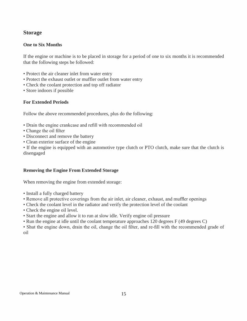
Storage
One to Six Months
If the engine or machine is to be placed in storage for a period of one to six months it is recommended that the following steps be followed:
• Protect the air cleaner inlet from water entry • Protect the exhaust outlet or muffler outlet from water entry • Check the coolant protection and top off radiator • Store indoors if possible For Extended Periods
Follow the above recommended procedures, plus do the following:
• Drain the engine crankcase and refill with recommended oil • Change the oil filter • Disconnect and remove the battery • Clean exterior surface of the engine • If the engine is equipped with an automotive type clutch or PTO clutch, make sure that the clutch is disengaged Removing the Engine From Extended Storage
When removing the engine from extended storage:
• Install a fully charged battery • Remove all protective coverings from the air inlet, air cleaner, exhaust, and muffler openings • Check the coolant level in the radiator and verify the protection level of the coolant • Check the engine oil level. • Start the engine and allow it to run at slow idle. Verify engine oil pressure • Run the engine at idle until the coolant temperature approaches 120 degrees F (49 degrees C) • Shut the engine down, drain the oil, change the oil filter, and re-fill with the recommended grade of oil
Operation & Maintenance Manual
15
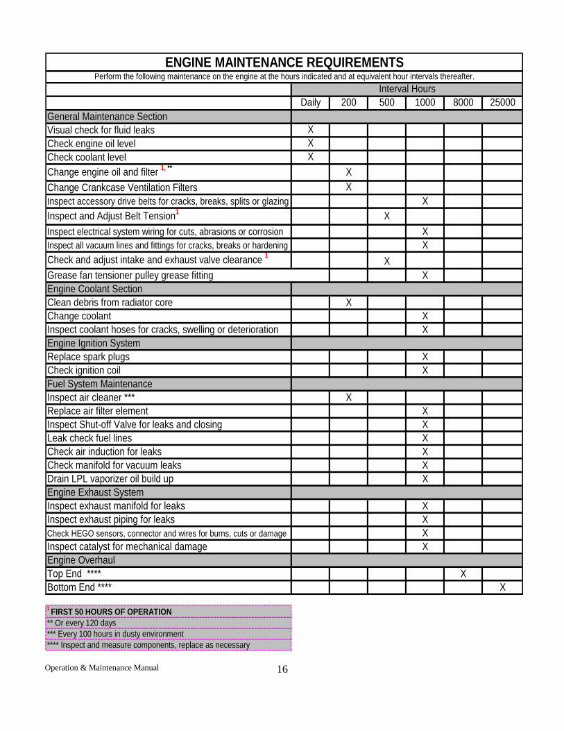
Daily 200 500 1000 8000 25000General Maintenance SectionVisual check for fluid leaks XCheck engine oil level XCheck coolant level XChange engine oil and filter 1, ** XChange Crankcase Ventilation Filters XInspect accessory drive belts for cracks, breaks, splits or glazing XInspect and Adjust Belt Tension1 XInspect electrical system wiring for cuts, abrasions or corrosion XInspect all vacuum lines and fittings for cracks, breaks or hardening XCheck and adjust intake and exhaust valve clearance 1 XGrease fan tensioner pulley grease fitting XEngine Coolant SectionClean debris from radiator core XChange coolant XInspect coolant hoses for cracks, swelling or deterioration XEngine Ignition SystemReplace spark plugs X Check ignition coil XFuel System MaintenanceInspect air cleaner *** XReplace air filter element XInspect Shut-off Valve for leaks and closing XLeak check fuel lines XCheck air induction for leaks XCheck manifold for vacuum leaks XDrain LPL vaporizer oil build up XEngine Exhaust SystemInspect exhaust manifold for leaks XInspect exhaust piping for leaks XCheck HEGO sensors, connector and wires for burns, cuts or damage XInspect catalyst for mechanical damage XEngine OverhaulTop End **** XBottom End **** X
1 FIRST 50 HOURS OF OPERATION** Or every 120 days*** Every 100 hours in dusty environment**** Inspect and measure components, replace as necessary
ENGINE MAINTENANCE REQUIREMENTSPerform the following maintenance on the engine at the hours indicated and at equivalent hour intervals thereafter.
Interval Hours
Operation & Maintenance Manual
16
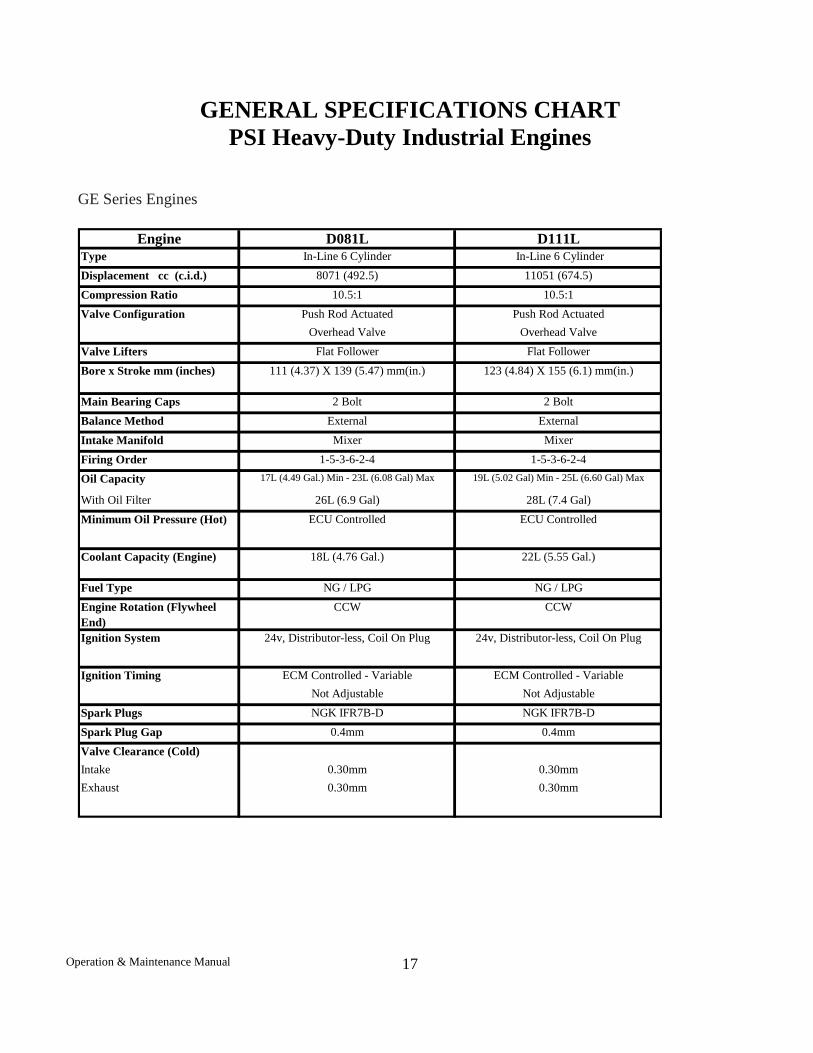
Engine D081L D111LType In-Line 6 Cylinder In-Line 6 CylinderDisplacement cc (c.i.d.) 8071 (492.5) 11051 (674.5)Compression Ratio 10.5:1 10.5:1
Push Rod Actuated Push Rod ActuatedOverhead Valve Overhead Valve
Valve Lifters Flat Follower Flat FollowerBore x Stroke mm (inches) 111 (4.37) X 139 (5.47) mm(in.) 123 (4.84) X 155 (6.1) mm(in.)
Main Bearing Caps 2 Bolt 2 BoltBalance Method External ExternalIntake Manifold Mixer MixerFiring Order 1-5-3-6-2-4 1-5-3-6-2-4Oil Capacity 17L (4.49 Gal.) Min - 23L (6.08 Gal) Max 19L (5.02 Gal) Min - 25L (6.60 Gal) Max
With Oil Filter 26L (6.9 Gal) 28L (7.4 Gal)
Coolant Capacity (Engine) 18L (4.76 Gal.) 22L (5.55 Gal.)
Fuel Type NG / LPG NG / LPGEngine Rotation (Flywheel End)
CCW CCW
ECM Controlled - Variable ECM Controlled - VariableNot Adjustable Not Adjustable
Spark Plugs NGK IFR7B-D NGK IFR7B-DSpark Plug Gap 0.4mm 0.4mmValve Clearance (Cold)Intake 0.30mm 0.30mmExhaust 0.30mm 0.30mm
ECU Controlled
Ignition System 24v, Distributor-less, Coil On Plug 24v, Distributor-less, Coil On Plug
ECU Controlled
Ignition Timing
Valve Configuration
Minimum Oil Pressure (Hot)
GENERAL SPECIFICATIONS CHART PSI Heavy-Duty Industrial Engines
GE Series Engines
Operation & Maintenance Manual
17
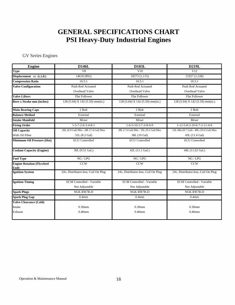
Engine D146L D183L D219LType V8 V10 V12Displacement cc (c.i.d.) 14618 (892) 18273 (1,115) 21927 (1,338)Compression Ratio 10.5:1 10.5:1 10.5:1
Push Rod Actuated Push Rod Actuated Push Rod ActuatedOverhead Valve Overhead Valve Overhead Valve
Valve Lifters Flat Follower Flat Follower Flat FollowerBore x Stroke mm (inches) 128 (5.04) X 142 (5.59) mm(in.) 128 (5.04) X 142 (5.59) mm(in.) 128 (5.04) X 142 (5.59) mm(in.)
Main Bearing Caps 2 Bolt 2 Bolt 2 BoltBalance Method External External ExternalIntake Manifold Mixer Mixer MixerFiring Order 1-5-7-2-6-3-4-8-1 1-6-5-10-2-7-3-8-4-9 1-12-5-8-3-10-6-7-2-11-4-9Oil Capacity 26L (6.9 Gal) Min - 28L (7.4 Gal) Max 28L (7.4 Gal) Min - 35L (9.2 Gal) Max 33L Min (8.7 Gal) - 40L (10.6 Gal) Max
With Oil Filter 31L (8.2 Gal) 38L (10 Gal) 43L (11.4 Gal)
Coolant Capacity (Engine) 36L (9.51 Gal.) 42L (11.1 Gal.) 44L (11.62 Gal.)
Fuel Type NG / LPG NG / LPG NG / LPGEngine Rotation (Flywheel End)
CCW CCW CCW
ECM Controlled - Variable ECM Controlled - Variable ECM Controlled - VariableNot Adjustable Not Adjustable Not Adjustable
Spark Plugs NGK IFR7B-D NGK IFR7B-D NGK IFR7B-DSpark Plug Gap 0.4mm 0.4mm 0.4mmValve Clearance (Cold)Intake 0.30mm 0.30mm 0.30mmExhaust 0.40mm 0.40mm 0.40mm
Valve Configuration
Ignition Timing
24v, Distributor-less, Coil On Plug 24v, Distributor-less, Coil On Plug 24v, Distributor-less, Coil On Plug
Minimum Oil Pressure (Hot)
Ignition System
ECU Controlled ECU Controlled ECU Controlled
GENERAL SPECIFICATIONS CHART PSI Heavy-Duty Industrial Engines
GV Series Engines
Operation & Maintenance Manual
18