Operation and Maintenance Instructions Manual manual covers John Deere Engines ... 3.5.2 Checking...
38
Operation and Maintenance Instructions Manual JU/JW MODEL ENGINES FOR FIRE PUMP APPLICATIONS This manual covers John Deere Engines prepared by Clarke for fire pump service Clarke UK, Ltd. Clarke Fire Protection Products, Inc. Unit 1, Grange Works 3133 E. Kemper Road Lomond Road Cincinnati, OH 45241 Coatbridge U.S.A. ML5 2NN United Kingdom TELE: +44(0)1236 429946 FAX: +44(0)1236 427274 TELE: +1.513.771.2200 FAX: +1.513.771.0726 www.clarkefire.com MP-7 12/06 C13960 rev G
Transcript of Operation and Maintenance Instructions Manual manual covers John Deere Engines ... 3.5.2 Checking...

Operation and Maintenance
Instructions Manual
JU/JW MODEL ENGINES FOR
FIRE PUMP APPLICATIONS
This manual covers John Deere Engines prepared by Clarke
for fire pump service
Clarke UK, Ltd. Clarke Fire Protection Products, Inc. Unit 1, Grange Works 3133 E. Kemper Road
Lomond Road Cincinnati, OH 45241 Coatbridge U.S.A. ML5 2NN
United Kingdom TELE: +44(0)1236 429946 FAX: +44(0)1236 427274
TELE: +1.513.771.2200 FAX: +1.513.771.0726
www.clarkefire.com
MP-7 12/06
C13960 rev G

Page 2 of 38
CONTENTS SUBJECT PAGE 1.0 INTRODUCTION 4
1.1 IDENTIFICATION/NAMEPLATE 4
1.2 SAFETY/CAUTION/WARNINGS 5
2.0 INSTALLATION/OPERATION 9
2.1 TYPICAL INSTALLATION 9
2.2 ENGINE STORAGE 10
2.2.1 Storage Less than 1 year 10
2.2.2 Extended Storage Maintenance Procedure 10
2.3 INSTALLATION INSTRUCTIONS 10
2.4 SPECIFIC FLYWHEEL COUPLING ALIGNMENT INSTRUCTIONS 12
2.4.1 Driveshaft 12
2.4.2 Other Coupling Types 13
2.5 WEEKLY TEST 14
2.6 STARTING/STOPPING THE ENGINE 14
2.6.1 Special Notes to Equipment Installer of an LPCB Approved (LPS1239) Engine Model 14
2.6.2 To Start Engine 14
2.6.3 To Stop Engine 17
3.0 ENGINE SYSTEMS 17
3.1 FUEL SYSTEM 17
3.1.1 Bleeding the Fuel System 17
3.1.1.1 JU4/6 UF, NL 17
3.1.1.2 JU4/6 LP 18
3.1.1.3 JW6 UF, NL 18
3.1.2 Draining the Condensate from the Fuel Filter 20
3.1.3 Changing Fuel Filter Cartridge 20
3.1.3.1 JU4/6 UF, NL 20
3.1.3.2 JU4/6 LP 21
3.1.3.3 JW6 UF, NL 21
3.1.4 Fuel Tanks 22
3.1.5 JU Fuel Injection Pump Components 22
3.1.6 JW Fuel Injection Pump Components 23
3.2 AIR/EXHAUST SYSTEM 23
3.2.1 Ambient Conditions 23
3.2.2 Ventilation 23
3.2.3 Standard Air Cleaner 23
3.2.4 Crankcase Ventilation 24
3.2.4.1 Open Crankcase Ventilation 24
3.2.4.2 Crankcase Ventilation System 24

Page 3 of 38
3.2.5 Exhaust System 25
3.3 LUBRICATION SYSTEM 25
3.3.1 Checking Sump Oil 25
3.3.2 Changing Engine Oil 26
3.3.3 Changing Oil Filter Cartridge 26
3.3.4 Oil Specification 26
3.3.5 Oil Capacities 27
3.4 COOLING SYSTEM 27
3.4.1 Engine Coolant 27
3.4.2 Water 27
3.4.3 Coolant Capacities 27
3.4.4 Coolant Inhibitors 27
3.4.5 Procedure for Filling Engine 28
3.4.5.1 Engines without Coolant Recovery Tank 28
3.4.5.2 Engines with Coolant Recovery Tank 29
3.5 ELECTRICAL SYSTEM 30
3.5.1 Wiring Diagrams 30
3.5.2 Checking Drive Belt Tension and Adjustment 30
3.5.3 Speed Switch 30
3.5.4 Magnetic Pick-Up 31
3.6 ENGINE SPEED ADJUSTMENT 31
4.0 MAINTENANCE SCHEDULE 31
4.1 ROUTINE MAINTENANCE 31
5.0 TROUBLE SHOOTING 32
6.0 PARTS INFORMATION 32
6.1 SPARES 32
6.2 ENGINE MAINTENANCE PARTS LIST 32
7.0 OWNER ASSISTANCE 33
8.0 WARRANTY 33
8.1 GENERAL WARRANTY STATEMENT 33
8.2 CLARKE WARRANTY 33
8.3 JOHN DEERE WARRANTY 33
9.0 ATCM CALIFORNIA EMISSION REGULATIONS FOR STATIONARY ENGINES 35
10.0 INSTALLATION & OPERATION DATA (See Technical Catalog C13965) 36
11.0 WIRING DIAGRAMS (See Technical Catalog C13965) 36
12.0 PARTS ILLLUSTRATION (See Technical Catalog C13965) 36
13.0 APPENIX (Alpha Index) 37

Page 4 of 38
Check factory availability for a manual in one of the following languages:
Spanish MP-7 C13961 French MP-7 C13962 German MP-7 C13963 Italian MP-7 C13964
NOTE The information contained in this book is intended to assist operating personnel by providing information on the characteristics of the purchased equipment. It does not relieve the user of their responsibility of using accepted practices in the installation, operation, and maintenance of the equipment. NOTE: CLARKE FPPG Reserves the right to update the contents of this publication without notice.

Page 5 of 38
1.0 INTRODUCTION SCOPE OF SUPPLY The following paragraphs summarize the “Scope of Supply” of the Engine:
• The CLARKE Engine supplied has been designed for the sole purpose of driving a stationary Emergency Fire Pump. It must not be used for any other purpose.
• Shall not be subjected to Horsepower
requirements greater than the certified nameplate rating (for UL/cUL/FM/LPCB only).
• Engines must be sized to cover fully the
maximum power absorbed by any particular driven equipment together with a safety factor on no less than 10%. (For Non-listed only).
• Derates for elevation and temperature need to
be considered for maximum pump power.
• Fuel delivery settings are factory set with-in the injection pump and must not be tampered with or adjusted. Minor RPM adjustments to meet pump requirements are permissible.
• The engine shall be installed and maintained
in accordance with the guidelines stated in this manual and technical catalog (C13965).
• Periodic running checks to ensure
functionality should be kept to a maximum of ½ hour per week.
1.1 IDENTIFICATION/NAMEPLATE
• Throughout this manual, the terms “Engine” and “Machine” are used.
• The term “Engine” refers solely to the diesel
engine driver as supplied by CLARKE.
• The term “Machine” refers to any piece of equipment with which the engine might interface.
This manual provides all the information necessary to operate your newly acquired engine safely and
efficiently, and perform routine servicing correctly. Please read it carefully. MODEL NUMBERING & IDENTIFICATION There are two identification plates attached to each engine. Clarke Identification Plate: Engine Model, Serial Number, Rating and Date of Manufacture are shown on this identification plate. The JU Series identification plate is mounted on the flywheel housing at the rear of the engine. The JW Series identification plate is mounted on right rear engine mount. Note that there are five types of identification plates, dependent on whether the engine is a “Non-Listed” or “Listed/Approved” Model. These are typical examples. (See Figure #1).
Clarke Identification Plates USA Non Listed USA Listed/Approved
UK Non-Listed UK Listed/Approved
Figure #1

Page 6 of 38
UK Listed/Approved
Figure #1 cont’d
Clarke model numbers reflects the base engine type, number of cylinders, cooling system, approval listing and a power rating code. Example: JU6H-UF50
• J = John Deere base engine prepared by CLARKE
• U = base engine series (4.5 liter 4 cylinder or 6.8 liter 6 cylinder)
• 6 = number of cylinders • H = Heat Exchanger cooled (R = Radiator) • UF = Underwriters Laboratories Listed/
Factory Mutual Approved, (LP = LPCB Loss Prevention Council Board Approved, NL = Non-Listed)
• 50 = A power rating code John Deere Identification Plate: The second identification plate contains the John Deere Model Number and Serial Number. On the JW Series, the John Deere Serial identification plate is located on the left-hand side of the engine between the intake manifold and starting motor. On the JU Series, the John Deere identification plate is located on the right side of the cylinder block behind the fuel filter. 1.2 SAFETY/CAUTION/WARNINGS ATTENTION: This engine has components and fluids that reach very high operating temperatures and is provided with moving pulleys and belts. Approach with caution. It is the responsibility of the builder of the machine using a Clarke engine to optimize the application in terms of maximum end user safety.
BASIC RULES The following recommendations are given to reduce the risk to persons and property when an engine is in service or out of service. Engines must not be used for applications other than those declared under “Scope of Supply”. Incorrect handling, modifications and use of non-original parts may affect safety. When lifting the engine, take care to use suitable equipment to be applied to the points specially provided as shown on the appropriate Engine Installation Drawing. Engine weights are shown in figure #2
ENGINE MODEL WEIGHT lbs (kg) JU4H-UF10, 12, 20, 22
JU4H-NL20, 22 JU4H-LP20,24
910 (413)
JU4H-UF30, 32, 40, 42, 50, 52, 8H, H0, H2, 58
JU4H-NL30, 32, 40, 42 JU4H-LP50,54
935 (424)
JU4H-LP84 1085 (492) JU4R-UF09, UF11,13,19,21,23 956 (434)
JU4R-UF40, 49, 51, 53 982 (445) JU6H-UF30, 32, 50, 52
D0, D2, G8, M8, M0, M2, 58 JU6H-NL30, 32, 50, 52
JU6H-LP50,54
1657 (750)
JU6H-UF60, 62, 68 JU6H-LP60,84
1693 (766) JW6H-UF30 (JDFP-06WA), 38
JW6H-NL30 2012 (910)
JW6H-UF40 (JDFP-06WR), 48 JW6H-NL40
2003 (906) JW6H-UF50, 60, 58
JW6H-NL50, 60 2053 (929)
Figure #2
Figure #3 shows the typical lifting arrangement of a bare engine. Note the lifting points on the engine are for lifting the engine only. Caution, when lifting, lift point should always be over the equipment Center of Gravity.

Page 7 of 38
Figure #3
Figure #4 shows the typical lifting arrangement of a base mounted engine and pump set when the base (or module) is furnished with lifting holes.
Figure #4
When Clarke furnishes the base (or module) for the engine and pump set, the combined weight of the engine and base (or module) will be indicated on the unit. Caution, when lifting, lift point should always be over the equipment Center of Gravity. Note: The engine produces a noise level exceeding 70 dB(a). When performing the weekly functional test, it is recommended that hearing protection be worn by operating personnel. CLARKE UK provides the machine manufacturer with a “Declaration of Incorporation” for the Engine, when required, a copy of which is enclosed in the manual. This document clearly states the machine manufacturers’ duties and responsibilities with respect to health and safety. Refer to Figure #5.

Page 8 of 38
GRANGE WORKS, LOMOND ROAD, COATBRIDGE, UNITED KINGDOM, ML5 2NN
TEL: 0044 1236 429946
FAX: 0044 1236 427274
DECLARATION OF INCORPORATION
We hereby declare that the following engine is intended to be incorporated into other machinery and must not be put into service until the relevant machinery, into which it is to be incorporated has been declared in conformity with the essential health and safety requirements of the Machinery Directive 89/392/EEC.
Description: - DIESEL ENGINES Model: - Serial Number: - Contract No: - Customers order no: NOTE: - This engine has moving parts, areas of high temperatures, and high temperature fluids under pressure. In addition it has an electrical system, which may be under strong current. The engine produces harmful gases, noise vibrations and as a result it is necessary to take Suitable precautionary measures when moving, installing and operating the engine to reduce risks connected with the characteristics stated above. The engine must only be used in accordance with the scope of supply and the intended application. STANDARDS AND TECHNICAL SPECIFICATIONS Signed: ____________________________ Date: ____________________________
REGISTERED IN SCOTLAND NO: 81670
C13896, Rev C, 3 Jan 2003 Figure #5 WHAT TO DO IN AN EMERGENCY Any user of the Engine who follows the instructions set out in this manual, and complies with the instructions on the labels affixed to the engine are working in safe conditions. If operating mistakes cause accidents call for help If operating mistakes cause accidents call for help immediately from the EMERGENCY SERVICES. In the event of an emergency, and while awaiting the arrival of the EMERGENCY SERVICES, the
following general advice is given for the provision of first aid. FIRE Put out the fire using extinguishers recommended by the manufacturer of the machine or the installation. BURNS
1) Put out the flames on the clothing of the burns victim by means of:
� drenching with water
Page 9 of 38
� use of powder extinguisher, making sure not to direct the jets onto the face
� blankets or rolling the victim on the ground
2) Do not pull off strips of clothing that are sticking to the skin.
3) In the case of scalding with liquids, remove the soaked clothing quickly but carefully.
4) Cover the burn with a special anti-burn packet or with a sterile bandage.
CARBON MONOXIDE POISONING (CO) Carbon monoxide contained in engine exhaust gases is odorless and dangerous because it is poisonous and with air, it forms an explosive mixture. Carbon monoxide is very dangerous in enclosed premises because it can reach a critical concentration in a short time. When attending a person suffering from CO poisoning in enclosed premises, ventilate the premises immediately to reduce the gas concentration. When accessing the premises, the person providing the aid must hold his breath, not light flames, turn on lights or activate electric bells or telephones so as to avoid explosions. Take the victim to a ventilated area or into the open air, placing him on his side if he is unconscious. CAUSTIC BURNS
1) Caustic burns to the skin are caused by acid escaping from the batteries:
� remove the clothes � wash with running water, being
careful not to affect injury-free areas 2) Caustic burns to the eyes are caused by
battery acid, lubricating oil and diesel fuel. � Wash the eye with running water for
at least 20 minutes, keeping the eyelids open so that the water runs over the eyeball and moving the eye in all directions.
ELECTROCUTION Electrocution can be caused by:
1) The engine’s electrical system (12/24 VDC)
2) The electrical coolant pre-heating system 120/240 Volt AC (if supplied) AC current.
In the first case, the low voltage does not involve high current flows through the human body; however, if there is a short circuit, caused by a metal tool, sparks and burns may occur. In the second case, the high voltage causes strong currents, which can be dangerous. If this happens, break the current by operating the switch before touching the injured person. If this is not possible, bear in mind that any other attempt is highly dangerous also for the person assisting; therefore, any attempt to help the victim must be carried out without fail using means that are insulating. WOUNDS AND FRACTURES The wide range of possible injuries and the specific nature of the help needed means that the medical services must be called. If the person is bleeding, compress the wound externally until help arrives. In the case of fracture do not move the part of the body affected by the fracture. When moving an injured person permission from that person must be received until you can help him. Unless the injury is life threatening, move the injured person with extreme care and then only if strictly necessary. WARNING LABELS Warning labels, in picture form, are applied to the engine. Their meanings are given below. Important Note: Labels that show an exclamation mark indicate that there is a possibility of danger.

Page 10 of 38
Heat Exchanger Maximum Working Pressure
Coolant Mixture
Lifting Point
Automatic Start
Rotating Parts
Jacket Water Heater Voltage
Air Filter Installation
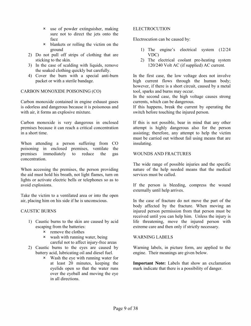
2.0 INSTALLATION/OPERATION 2.1 TYPICAL INSTALLATION A typical Fire Pump installation is shown in Figure #6 & 6A. 1. Pump/Engine set 2. Main Pump Controller 3. Pump discharge 4. Air louver 5. Entrance door with air louver 6. Exhaust silencer 7. Exhaust system supports 8. Exhaust outlet pipe 9. Concrete base 10. Exhaust flexible connection joint/pipe 11. Air Discharge Duct from Radiator
Figure #6
Typical Installation Heat Exchanger Cooled Engine
Page 11 of 38
Figure #6A
Typical Installation Radiator Cooled Engine
2.2 ENGINE STORAGE 2.2.1 Storage less than 1 year Storing engines requires special attention. Clarke engines, as prepared for shipment, may be stored for a minimum of one year. During this period, they should be stored indoors in a dry environment. Protective coverings are recommended provided they are arranged to allow for air circulation. The stored engine should be inspected periodically for obvious conditions such as standing water, part theft, excess dirt buildup or any other condition that may be detrimental to the engine or components. Any such conditions found must be corrected immediately. 2.2.2 Extended Storage Maintenance Procedure After a one year storage period or if the engine is being taken out of service for more than 6 months, additional preservation service must be performed as follows:
1) Drain the engine oil and change the oil filter. 2) Refill the engine crankcase with MIL-L-
21260 preservative oil. 3) Change the fuel filter. 4) Install the coolant plugs and install coolant in
the normal mix percentage of 50% coolant, 50% water, premixed.
5) Remove the protection from the intake and exhaust openings.
6) Prepare a container as a fuel source using a mixture of Mobilarma or Sta-Bil with Diesel #2 fuel or “Red” diesel fuel (ASTM D-975) or BS2869 Class A2.
7) Disconnect the coupling or drive shaft from the pump.
8) Start and run the engine at a slow speed for 1-2 minutes being careful not to exceed the normal operating temperature.
9) Drain the oil and coolant. 10) Replace the protective plugs that were used
for shipping and storage. 11) Attach to the engine a visible card, specifying
“ENGINE WITHOUT OIL” DO NOT OPERATE”.
IMPORTANT: THIS TREATMENT MUST BE REPEATED EVERY 6 MONTHS ************************ PUTTING ENGINE INTO SERVICE AFTER ADDITIONAL PRESERVATION SERVICE: To restore the normal operation running conditions of the engine, carry out the following:
1) Fill the engine sump with the normal recommended oil, to the required level.
2) Remove the protective plugs used for shipping and storage.
3) Refill cooling water to proper level. 4) Remove the card “ENGINE WITHOUT OIL,
DO NOT OPERATE”. 5) Follow all steps of the Installation
Instructions when the engine will be put into service.
2.3 INSTALLATION INSTRUCTIONS The correct installation of the engine is very important to achieving optimum performance and extended engine life. In this respect, the engine has certain installation requirements, which are critical to how it performs. These requirements are generally associated with the cooling, exhaust, induction air, and fuel systems. This section of the manual should be read in conjunction with the relevant Installation and Operation Data Sheets. If there is any doubt about an installation, contact should be made with Clarke Customer Support giving exact details of the problem. All installations should be clean, free of any debris and dry. Care should be taken to ensure that there is easy access to the engine for maintenance and repair. The safety of personnel who may be in the area of the
11
Page 12 of 38
engine when it is running is of paramount importance when designing the installation layout.
1) Secure pump set to foundation and complete installation in accordance with pump manufacturer’s instructions. Perform engine-to-pump coupling alignment. Lubricate Falk coupling with supplied grease or driveshaft universal joints with NLGI grade #1 or #2 grease at the (3) Zerk fittings. (Refer to section 2.4 for specific alignment instructions).
2a) Engine with Heat Exchanger Cooling: Install the heat exchanger discharge pipe. The discharge pipe should be no smaller than the outlet connection on the heat exchanger. Discharge water piping should be installed in accordance with applicable codes. All plumbing connecting to the heat exchanger must be secured to minimize movement by the engine. Cooling loop water pressure to the heat exchanger must not exceed the limit that is stated on the heat exchanger supplied with the engine.
2b) Engine with Radiator Cooling: Connect radiator air discharge ducting to radiator duct flange. Discharge ducting should be installed in accordance with applicable codes. A flexible duct section should be provided to isolate engine from building.
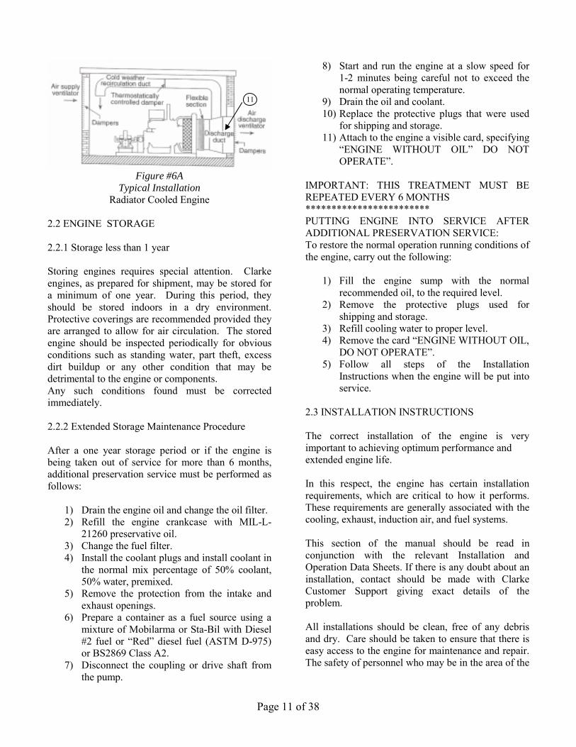
3) Install all engine cooling system draincocks and plugs.
Qty
Description
Location
Engine Model
1 1/8” draincock
Water Heater inlet tube
JU4/6H, JU4/6R
1 1/8” draincock
Coolant heater inlet tube
JDFP, JW6
1 Plug RE46686
Oil Cooler JU4/6H,JU4/6R
1 3/8” pipe plug Heat exchanger JDFP, JW6
1 Electrode plug
Bottom of heat exchanger
JU4/6H
4) Fill engine cooling system with premixed 50% water / 50% coolant solution. Use only coolants meeting ASTM-D4985 specifications for heavy-duty diesel engines. Never use light-duty or automotive coolants in the engine that are stated as ASTM-D3306 only. Refer to Figure #34 in section 3.4.3
for cooling system capacity. Refer to section 3.4.5 for filling procedure.
5) Engine is shipped with oil installed. For make-up oil specification refer to section 3.3 Lubrication System.
6) Connect fuel supply and return line to fuel supply tank plumbing. Reference the Fuel System section of the Installation and Operation Data in the Technical Catalog, for piping size, maximum allowable fuel pump suction, and maximum allowable fuel head requirements. Fill supply tank with #2 diesel fuel (ASTM D-975) or BS 2869 Class A2 “Red” diesel fuel, bleed supply system of air and check for leaks. Fuel supply level must meet applicable code requirements. Do not use a copper based or galvanized material for any component of a diesel fuel system. The fuel will chemically react with the zinc resulting in clogged fuel filters and injector systems.
7) Remove protective covering on air cleaner element.
8) Connect jacket water heater (if supplied) to AC power source. For JU4/6 Series the electrical supply requirements are indicated on the heater body. Connect the supplied heater connection wire directly to a customer supplied electrical junction box. For JDFP/JW6 Series the electrical supply requirements are indicated on the connection box. Connect to the heater directly to the junction box at the end of the heater only. Supply wiring should never be routed through the engine gauge panel. Severe damage to critical engine control components could result. Energize heater only after step #4 is completed.
9) Connect exhaust system to flexible connection on the engine. The exhaust system plumbing must be supported by the building structure and not the engine. The exhaust flexible connection is provided only for the purpose of thermal expansion and vibration isolation, not for misalignment or directional change.
10) Make electrical DC connections between the engine gauge panel terminal strip (if supplied) and the controller per the controller manufacturer’s instructions. Note that the “W” terminal is used only for the UL/FM cooling water solenoid (if supplied). Refer to
Page 13 of 38
the wiring diagram sticker located on the inside cover of the engine gauge panel for proper connection of the water solenoid.
11) Fill batteries with electrolyte per battery manufacturer’s instructions. Connect cables between engine and batteries only after electrolyte is installed. Refer to the wiring diagram inside the engine gauge panel cover (if supplied), or appropriate wiring diagram in the Technical Catalog C13965, for correct positive and negative connections. Connect negative cables directly to the engine block. On JU4/6 Series connect each positive cable to the large electrical post of the starter motor. Note: the JU4/6 Series have a separate starter motor for each battery set. On the JDFP/JW6 Series connect each positive cable to the large outer post of the manual starting contactors.
12) Note: Clarke Operation and Maintenance Instructions Manual and Clarke parts illustration pages are located inside the engine gauge panel.
13) IMPORTANT! In order to obtain prompt Warranty Service and to comply with Emissions Regulations, this engine must be registered to the final installation name and address. To register this engine, go to www.clarkefire.com and select Warranty Registration.
2.4 SPECIFIC FLYWHEEL COUPLING
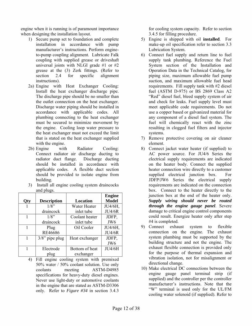
ALIGNMENT INSTRUCTIONS 2.4.1 Driveshaft To check the alignment of the pump shaft and engine crankshaft centerlines for proper Parallel Offset and Angular tolerance, the driveshaft must be installed between the flywheel drive disc (no drive disc on JW6 models) and the flanged hub on the pump shaft. Before removing the driveshaft guard, disconnect the negative battery cable from both batteries. Before beginning the alignment checks and making any necessary corrections, install the driveshaft and re-torque all driveshaft connection bolts to the values given in the following table:
MODELS
DRIVE SHAFT
BOLT SIZE /MATERIAL
GRADE
TIGHTENING TORQUE
ft-lbs (N-m)
JU4-UF09, 10,11,12,13,19,
20,2122,23 JU4-LP 20,24
SC41
7/16-20 Grade 8
(Hi-Tensile)
50 + 55
(68 – 75)
JU4-UF 30,32,40,42,50,51,52,53, H8,
H0, H2, 58 JU4-LP 50,54
SC55
1/2-20
Grade 8 (Hi-Tensile)
75 + 82.5
(102 – 112)
All JU6 & JW6
SC2130
M12,Class
10.9 (Metric)
(Hi-Tensile)
90 + 99 (122 – 134) (see note #1)
86 – 94
(117 - 128) (see note #2)
Note 1 – It is recommended that a medium strength threadlocker (i.e. Loctite – blue #64040) be used in the assembly and torquing of all hardware. This may be purchased as part number 23509536. Note 2 – 4 of the hi-tensile bolts and/or nuts, that are used to connect the driveshaft to the drive disc (all JU6 models) or flywheel (all JW6 models) and that connect the driveshaft to the pump companion flange, will require a “crow’s foot” wrench attached to a standard torque wrench in order to apply the required tightening torque. A standard socket will not work due to close proximity of the bolts and/or nuts with the driveshaft yoke. The tightening torque values listed for these bolts and/or nuts have been corrected for using a standard “crow’s foot” adapter. The following steps describe the proper way to check alignment. A small pocket scale or ruler with millimeter markings is recommended to make all measurements. A) To check the Horizontal Parallel Offset, the
driveshaft must be in the proper orientation. 1. Rotate the shaft so the reference “AB” on the
flywheel disc or the circumference of the drive shaft flange (against the flywheel) is in the 12 o’clock position shown on figure# 7.
2. Measure from the rear face of the flywheel drive disc or the drive shaft flange to point A. (Point A is on the bearing bore as shown in

Page 14 of 38
Figure 7, on the instrument panel side of the engine). This measurement must be:
MEASUREMENT MODELS 58 + 2mm. JU4-UF
09,10,11,12,13,19, 20, 21,22,23
JU4-LP20,24 68 + 4mm. JU4-UF30, 32, 40, 42,
49, 50, 51, 52, 53, 8H, H0, H2, 58
JU4-LP 50,54 76 + 3mm. All JU6 & JW6
B) With the driveshaft in the same orientation as the previous step (Step A), check the Horizontal Angular alignment of the shafts. 1. Measure from the front face of the drive shaft
flange on the pump end to point B. (Point B is the bearing bore on the exhaust side of the engine). This measurement must be equal to the measurement at point A + 1 mm.
C) To check the Vertical Parallel Offset, the driveshaft must be re-orientated. 1. Rotate the shaft 90○ so the reference “CD” on
the flywheel drive disc or the circumference of the drive shaft flange (against the flywheel) is in the position shown on Figure#8.
2. Measure from the rear face of the flywheel drive disc or the drive shaft flange to point C. (Point C is the same as point A with the driveshaft rotated 90°). The measurement must be:
MEASUREMENT MODELS 60 + 1mm. JU4-UF 09,10,11,12,13,
20,21,22,23 JU4-LP20,24
71 + 1mm. JU4-UF30, 32, 40, 42, 49,50,51,52,53, 8H, H0,
H2, 58 JU4-LP 50,54
78 + 1mm. All JU6 & JW6 D) With the driveshaft in the same orientation as the
previous step (Step C), check the Vertical alignment of the shafts. 1. Measure the front face of the drive shaft
flange on the pump end to point D. (Point D is the same as point B, with the driveshaft rotated 90). The measurement must be equal to the measurement at point C + 1 mm.
Re-install all guards and grease fittings vefore reconnecting the battery cables.
Figure #7
Figure #8
DRIVESHAFT MAINTENANCE
1. To service the driveshaft disconnect the negative battery cables, remove the top of guard and set aside.
2. Rotate engine shaft manually so the u-joint grease fittings are accessible.
3. Using a hand held grease gun with N.L.G.I. grade 1 or 2 grease position on grease fitting. Pump with grease until grease is visible at all four cap seals.
4. Verify all driveshaft connecting bolts remain tight. Re-torque per 2.4.1 if necessary.
5. Reinstall top of guard and connect negative battery cables.
2.4.2 Other Coupling Types
Consult Factory or Clarke website at [email protected] for additional information.

Page 15 of 38
2.5 WEEKLY TEST An experienced operator should be present during the weekly test. NOTE: This engine is designed to operate at rated load conditions. For testing purposes the engine can be run at lower load (lower flow) conditions. Running times in any one period should not exceed 30 minutes maximum. Before starting the engine make sure of the following:
1) The operator has free access to stop the engine in an emergency.
2) The plant room ventilation ducts are open and the engine has good access for air.
3) All the guards are in position and, if not, for whatever reason, any rotating parts will be free and clear without restriction.
4) Battery covers are in place and there is nothing on top of or touching the engine, which is not part of the original supply specification.
5a) Heat Exchanger Cooling: The water supply for coolant is available again without restriction.
5a) Radiator Cooling: The air supply for cooling is available again without restriction.
When engine is running make sure that the coolant temperature and oil pressure raw cooling water flow are within the limits specified on the relevant Installation & Operation Data Sheet in the Technical Catalog, C13965. If the coolant temperature is excessive, check:
a) Cooling loop strainers b) Proper functioning of thermostat c) Condition of heat exchanger tube bundle
2.6 STARTING/STOPPING THE ENGINE 2.6.1 Special Notes to Equipment Installer of an
LPCB Approved (LPS1239) Engine Model Any device fitted to the engine or controller, which could prevent the engine starting automatically, shall
return automatically to the normal position after manual application. The electrical fuel shutoff actuator shall be connected to an Engine Stop button on the main pump controller. The main pump controller shall de-energize the start motor when the engine has achieved 700-1000 rpm. 2.6.2 To Start Engine Use main pump controller for starting. Follow instructions provided by controller manufacturer. On UL/FM engines, use main pump controller for starting and stopping the engine. Should the main pump controller become inoperable, the engine can be manually started and stopped from the engine gauge panel. For manual starting and stopping of an engine with a gauge panel: Position MODE SELECTOR to MANUAL RUN. (Refer to Figure #9). Lift and hold MANUAL CRANK #1, until engine starts, or release after 15 seconds. If unit fails to start, wait for 15 seconds, use MANUAL CRANK #2 and repeat step. If COOLING WATER is not flowing or engine TEMPERATURE is too HIGH, open cooling system manual by-pass valves (applies to heat exchanger cooled engines only). Note: On JW Engines you can also start engines using manual starting contactors. On LPCB engines, use main pump controller for starting and stopping the engine. Should the main pump controller become inoperable, the engine can be manually started from the engine gauge panel. For manual starting of an engine with a gauge panel. (Refer to Figure #9A): Lift and hold MANUAL CRANK #1, until engine starts, or release after 15 seconds. If unit fails to start, wait for 10 seconds, use MANUAL CRANK #2 and repeat step. If COOLING WATER is not flowing or engine TEMPERATURE is too HIGH, open cooling system manual by-pass valves (applies to heat exchanger cooled engines only).

Page 16 of 38
UL/FM Instrument Panel
Figure #9
1 – Emergency Operating Instructions 4 – Overspeed Reset 2 – Automatic-Manual Mode Selector 5 – Warning Light 3 – Manual Crank Controls 6 – Overspeed Verification

Page 17 of 38
LPCB Instrument Panel
Figure #9A
1 – Emergency Operating Instructions 2 – Manual Crank Controls
1
2 2
2

Page 18 of 38
IMPORTANT: Main pump controller selector should be in the OFF position when starting from engine gauge panel. Be sure to return selector on main pump controller and engine gauge panel to AUTOMATIC after completing manual run. 2.6.3 To Stop Engine If engine is started from main pump controller use main pump controller to stop the engine. If engine is started from engine gauge panel: Return MODE SELECTOR switch to AUTOMATIC/MANUAL STOP position, engine will stop. Close cooling system manual by-pass valve if opened. IMPORTANT: DO NOT leave the MODE SELECTOR switch in the MANUAL RUN position during AUTOMATIC operation. (The controller will be unable to stop the engine and DAMAGE MAY RESULT). Engines not equipped with an engine gauge panel, and LPCB engines, have a manual shutdown lever on the engine for shutdown. 3.0 ENGINE SYSTEMS 3.1 FUEL SYSTEM 3.1.1 Bleeding the Fuel System CAUTION: Escaping fluid under pressure can penetrate the skin causing series injury. Relieve pressure before disconnecting fuel or other lines. Tighten all connections before applying pressure. Keep hands and body away from pinholes and nozzles, which eject fluids under high pressure. Use a piece of cardboard or paper to search for leaks. Do not use your hand. If ANY fluid is injected into the skin, it must be surgically removed within a few hours by a doctor familiar with this type injury or gangrene may result. Doctors unfamiliar with this type of injury may call the Deere & Company Medical Department in Moline, Illinois, or other knowledgeable medical source. Ref figure #10
Whenever the fuel system has been opened up for service (lines disconnected or filters removed), it will be necessary to bleed air from the system. 3.1.1.1 JU4/6-UF,NL Engine Series:
1) Loosen the air bleed vent screw (A) two full turns by hand on fuel filter base. Ref. Figure #11
2) Operate supply pump primer lever (B) until fuel flow is free from air bubbles. Ref. Figure #12.
3) Tighten bleed plug securely; continue operating hand primer until pump action is not felt. Push hand primer inward (toward engine) as far as it will go.
4) Start engine and check for leaks.
Figure #11
Figure #10
A

Page 19 of 38
Figure # 12 If engine will not start, it may be necessary to bleed air from fuel system at fuel injection pump or injection nozzles as explained next. At Fuel Injection Pump:
1) Slightly loosen fuel return line connector (A) at fuel injection pump. Ref figure #13
2) Operate fuel supply pump primer lever until fuel, without air bubbles, flows from fuel return line connection.
3) Tighten return line connector at 16N-m (12 lb-ft).
4) Leave hand primer in the inward position toward cylinder block. Ref. Figure #14.
Figure # 13
Figure #14
3.1.1.2 JU4/6 LP Engine Series
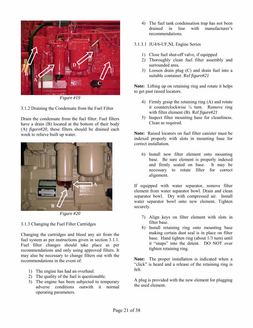
Photo to follow later 3.1.1.3 JDFP/JW6 Engine Series: Refer to Figure #19 for system components location. A – Primary Fuel Filter B – Secondary Fuel Filter C – Fuel Injection Pump D – Speed Adjustment At Round Primary Fuel Filter/Water Separator:
1) Drain water and contaminants from clear sediment bowl.
2) Loosen air bleed vent screw (A) on fuel filter base (Figure# 15)
3) Operate and primer (B) until fuel flow is free from air bubbles (Figure#15)
4) Tighten vent screw as hand primer is held in downward pumping position.
B
A
B

Page 20 of 38
Figure # 15 At Rectangular Final Fuel Filter:
1) Loose bleed plug (A) on fuel filter base (figure#16).
2) Operate hand primer (B) on fuel supply pump (figure#17), until a smooth flow of fuel, free of bubbling, comes out of the plug hole.
3) Simultaneously stroke the hand primer down and close the filter port plug. This prevents air from entering the system. Tighten plug securely. DO NOT over tighten.
4) Start engine and check for leaks.
Figure #16
Figure #17
If engine will not start, it may be necessary to bleed air from fuel system at injection nozzles as explained below. At Fuel Injection Nozzle
1) Loosen fuel line connection at no. 1 injection nozzle (A) (figure#18)
2) Crank engine with starting motor (but do not start engine), until fuel free from bubbles flows out of loosened connections. Retighten connection.
3) Start engine and check for leaks. 4) If engine does not start, repeat procedure at
remaining injection nozzles (if necessary) until enough air has been removed from fuel system to allow engine to start.
Figure #18
A
B
A
A
Page 21 of 38
Figure #19
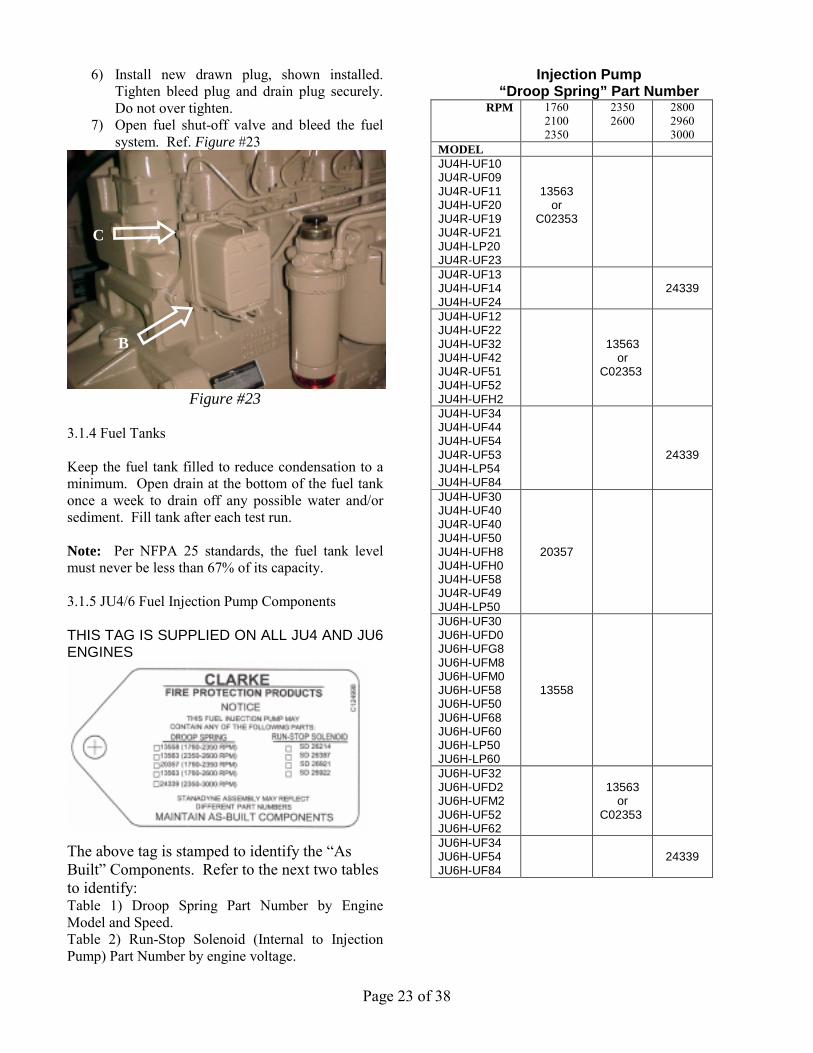
3.1.2 Draining the Condensate from the Fuel Filter Drain the condensate from the fuel filter. Fuel filters have a drain (B) located at the bottom of their body (A) figure#20, these filters should be drained each week to relieve built up water.
Figure #20
3.1.3 Changing the Fuel Filter Cartridges Changing the cartridges and bleed any air from the fuel system as per instructions given in section 3.1.1. Fuel filter changes should take place as per recommendations and only using approved filters. It may also be necessary to change filters out with the recommendations in the event of:
1) The engine has had an overhaul. 2) The quality of the fuel is questionable. 3) The engine has been subjected to temporary
adverse conditions outwith it normal operating parameters.
4) The fuel tank condensation trap has not been drained in line with manufacturer’s recommendations.
3.1.3.1 JU4/6-UF,NL Engine Series
1) Close fuel shut-off valve, if equipped 2) Thoroughly clean fuel filter assembly and
surrounded area. 3) Loosen drain plug (C) and drain fuel into a
suitable container. Ref figure#21 Note: Lifting up on retaining ring and rotate it helps to get past raised locators.
4) Firmly grasp the retaining ring (A) and rotate it counterclockwise ¼ turn. Remove ring with filter element (B). Ref figure#21
5) Inspect filter mounting base for cleanliness. Clean as required.
Note: Raised locators on fuel filter canister must be indexed properly with slots in mounting base for correct installation.
6) Install new filter element onto mounting base. Be sure element is properly indexed and firmly seated on base. It may be necessary to rotate filter for correct alignment.
If equipped with water separator, remove filter element from water separator bowl. Drain and clean separator bowl. Dry with compressed air. Install water separator bowl onto new element. Tighten securely.
7) Align keys on filter element with slots in filter base.
8) Install retaining ring onto mounting base making certain dust seal is in place on filter base. Hand tighten ring (about 1/3 turn) until it “snaps” into the detent. DO NOT over tighten retaining ring.
Note: The proper installation is indicated when a “click” is heard and a release of the retaining ring is felt. A plug is provided with the new element for plugging the used element.
A B
C
D
A
B

Page 22 of 38
9) Open fuel shut-off valve and bleed the fuel system. Tighten bleed plug (D). Reference Figure #21
Figure #21
3.1.3.2 JU4/6 LP Engine Series 3.1.3.3 JDFP/JW6 Engine Series Each engine has two fuel filters. For the purpose of identity, the primary filter incorporates the transparent water separator. Replacing (round) Primary Fuel Filter/Water Separator
1) Close fuel shut-off valve at bottom of fuel tank, if equipped.
2) Thoroughly clean fuel filter/water separator assembly and surrounding area.
Note: Lifting up on retaining ring (F) as it is rotated helps to get it past retaining dent. Ref. Figure #22
3) Rotate retaining ring counterclockwise ¼ turn. Remove ring with filter element.
4) Remove water separator bowl (G) from filter element (E). Drain and clean separator bowl. Dry with compressed air. Ref. Figure #22
Note: Notice raised locators on filter element. These locators insure proper alignment of filter element to filter base.
5) Install water separator bowl onto new filter element. Tighten securely.
6) Index filter element until longer, vertical locator (D) is oriented opposite mounting base. Insert filter element into base securely.
It may be necessary to rotate filter for correct alignment. Ref. Figure #22
7) Install retaining ring to filter base, making certain dust seal (C) is in place on filter base. Tighten retaining ring until it locks into detent position and a “click” sound can be heard. Ref. Figure #22
8) Bleed fuel system.
Figure #22
Replacing (rectangular) Secondary Fuel Filter Element
1) Close fuel shut-off valve at bottom of fuel
tank, if equipped. 2) Loosen bleed plug (C) on side of filter base.
Remove drain plug (B) to drain from fuel filter. Ref. Figure #23
Note: Keep a small container under drain plug to catch draining fuel.
3) With fuel filter firm against base, lift up on top retaining spring and pull down on bottom retaining spring. Pull fuel filter off guide pins of fuel filter base and discard.
4) Install new fuel filter onto guide pins of fuel filter base. Hold filter firmly against base.
5) Secure bottom filter retaining spring first, then secure top retaining spring (four arrows).
C B
A
D
Page 23 of 38
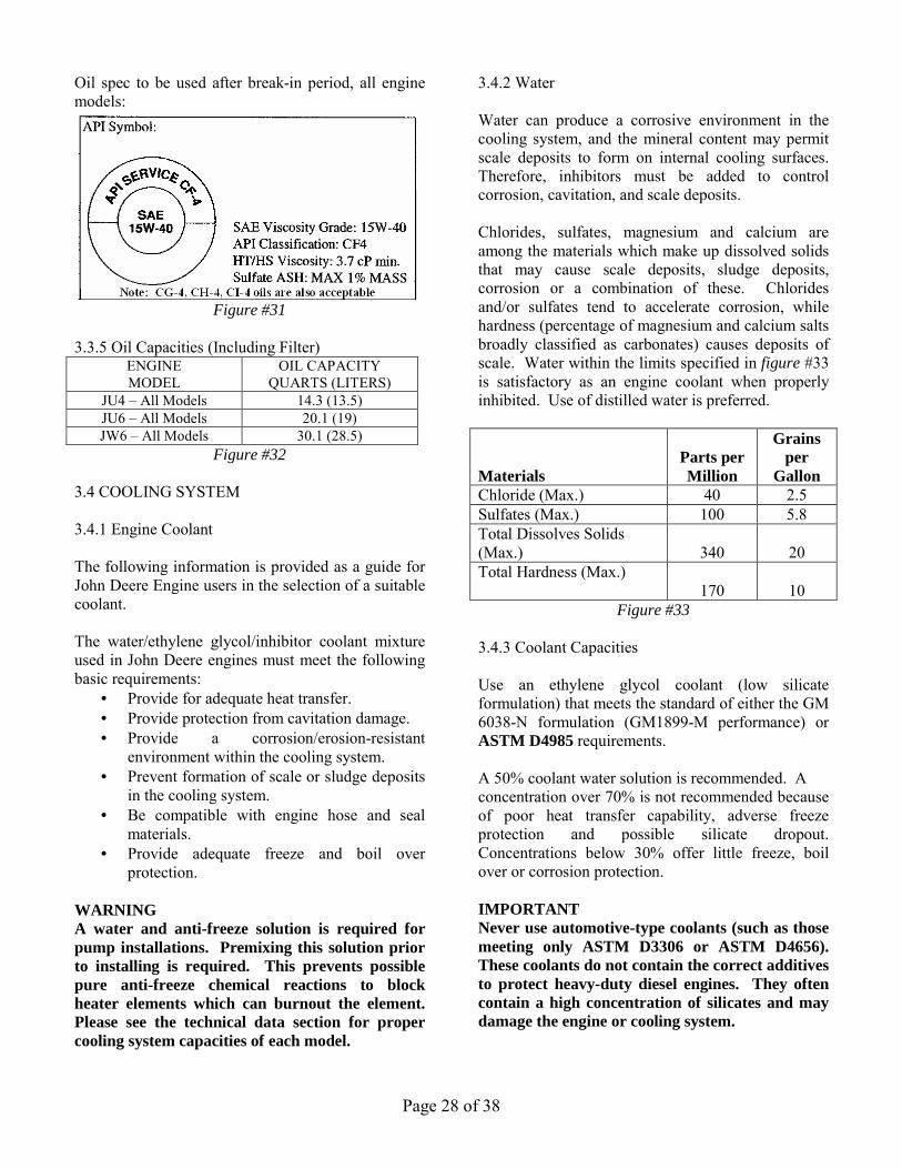
6) Install new drawn plug, shown installed. Tighten bleed plug and drain plug securely. Do not over tighten.
7) Open fuel shut-off valve and bleed the fuel system. Ref. Figure #23
Figure #23 3.1.4 Fuel Tanks Keep the fuel tank filled to reduce condensation to a minimum. Open drain at the bottom of the fuel tank once a week to drain off any possible water and/or sediment. Fill tank after each test run. Note: Per NFPA 25 standards, the fuel tank level must never be less than 67% of its capacity. 3.1.5 JU4/6 Fuel Injection Pump Components THIS TAG IS SUPPLIED ON ALL JU4 AND JU6 ENGINES
The above tag is stamped to identify the “As Built” Components. Refer to the next two tables to identify: Table 1) Droop Spring Part Number by Engine Model and Speed. Table 2) Run-Stop Solenoid (Internal to Injection Pump) Part Number by engine voltage.
Injection Pump “Droop Spring” Part Number
RPM 1760 2100 2350
2350 2600
2800 2960 3000
MODEL JU4H-UF10 JU4R-UF09 JU4R-UF11 JU4H-UF20 JU4R-UF19 JU4R-UF21 JU4H-LP20 JU4R-UF23
13563 or
C02353
JU4R-UF13 JU4H-UF14
JU4H-UF24
24339
JU4H-UF12 JU4H-UF22 JU4H-UF32 JU4H-UF42
JU4R-UF51 JU4H-UF52 JU4H-UFH2
13563 or
C02353
JU4H-UF34 JU4H-UF44 JU4H-UF54
JU4R-UF53 JU4H-LP54 JU4H-UF84
24339
JU4H-UF30 JU4H-UF40 JU4R-UF40 JU4H-UF50 JU4H-UFH8 JU4H-UFH0 JU4H-UF58 JU4R-UF49 JU4H-LP50
20357
JU6H-UF30 JU6H-UFD0 JU6H-UFG8 JU6H-UFM8 JU6H-UFM0 JU6H-UF58 JU6H-UF50 JU6H-UF68 JU6H-UF60 JU6H-LP50 JU6H-LP60
13558
JU6H-UF32 JU6H-UFD2 JU6H-UFM2 JU6H-UF52 JU6H-UF62
13563
or C02353
JU6H-UF34 JU6H-UF54 JU6H-UF84
24339
B
C

Page 24 of 38
Run-Stop Solenoid Part Number ETR ETS
12 Volt SD26214 or C07853
SD26921 or C07827
24 Volt SD26387 or C07826
SD26922 or C07828
Legend: ETR – Energized to Run ETS – Energized to Stop SD # - Stanadyne Part Number C # - Clarke Part Number 3.1.6 JW6 Fuel Injection Pump Components For Droop Spring and Run-Stop Solenoid (external to Injection Pump) part numbers consult factory. 3.2 AIR/EXHAUST SYSTEM 3.2.1 Ambient Conditions Clarke engines are tested in accordance with SAE J1349 (Clarke USA) or ISO 3046 (Clarke UK). In this capacity they may be derated to meet certain site conditions, failure to do so can seriously impede the performance of the engine and could lead to premature failure. 3.2.2 Ventilation The engine must be provided with adequate ventilation to satisfy the requirements of the combustion system, radiator cooling systems where fitted, and allow adequate dissipation of radiated heat and crankcase emissions. For all this data refer to Installation & Operation Data in Technical Catalog, C13965. This data can be used for proper sizing of inlet and outlet louvers. 3.2.3 Standard Air Cleaner The standard air cleaner is a reusable type. Should a situation occur where the air cleaner becomes plugged with dirt (starving the engine of air), loss of power and heavy black smoke will result; the air cleaner should be serviced immediately. See figure #39 for air cleaner part numbers by Clarke Engine Model. CAUTION: Do not attempt to remove the air cleaner while an engine is running nor run the engine while the air cleaner is off. Exposed components could cause severe injury to personnel and major
internal engine damage could occur should any foreign matter be drawn into the engine. The air cleaner manufacturer recommends the following:
1. The pre-oiled reusable elements are serviced with a special oil. The elements can be serviced or replaced.
2. Figure #24 shows the air filter service instructions.
3. When servicing the element is not practical, you can improve filter efficiency by re-spraying with oil.
NOTE: Do not attempt this while engine is running NOTE: Do not over oil the reusable element
Figure #24

Page 25 of 38
Figure #24 (cont’d) 3.2.4 Crankcase Ventilation 3.2.4.1 Open Crankcase Ventilation (Refer to fig#27b) Vapors which may form within the engine are removed from the crankcase and gear train compartment by a continuous, pressurized ventilation system. A slight pressure is maintained within the engine crankcase compartment. Vapors expelled through a vent pipe attached to the rocker cover breather element. Ref. Figure #25, 26, & 27.
Figure #25
JU4-UF10, 12, 20, 22, JU4-LP20, 24
Figure #26
JU4-UF30, 32, 40, 42, 50, 52, H8, H0, H2, 58 JU4-LP50, 54 & JU6 All
Figure #27 JDFP/JW6
3.2.4.2 Crankcase Ventilation System A crankcase ventilation system allows for the recirculation of vapors (expelled through a vent pipe attached to the rocker cover breather element) to the combustion air inlet. Refer to figure 27a.
Figure #27a

Page 26 of 38
Engine Model
Open Crankcase Ventilation
Crankcase Ventilation
System JU4R-UF09 JU4H-UF10 JU4R-UF11 JU4H-UF12 JU4R-UF19 JU4H-UF20 JU4H-LP20 JU4R-UF21 JU4H-UF22 JU4R-UF23 JU4H-UF30 JU4H-UF32 JU4H-UF40 JU4R-UF40 JU4H-UF42 JU4R-UF49 JU4H-UF50 JU4H-LP50
JU4R-UF51 JU4H-UF52 JU4H-UF58 JU4H-UFH2 JU4H-UFH8 JU4H-UFH0 JU6H-UF30 JU6H-UF32 JU6H-UF50 JU6H-LP50 JU6H-UF52 JU6H-UF58 JU6H-UF62 JU6H-UF68 JU6H-UF60 JU6H-LP60 JU6H-UFD0 JU6H-UFG8 JU6H-UFM8 JU6H-UFM0 JU6H-UFD2 JU6H-UFM2
Standard
Optional
Figure #27b
Engine Model
Open Crankcase Ventilation
Crankcase Ventilation
System JU4H-UF34 JU4H-UF44 JU4H-UF54
JU4R-UF53 JU4H-LP54 JU4H-UF84 JU6H-UF34 JU6H-UF54 JU6H-UF84
Standard
Figure #27b cont’d
3.2.5 Exhaust System Excessive back pressures to the engine exhaust can considerably reduce both engine performance and life. It is therefore important that exhaust systems should be the proper diameter and be as short as possible within the minimum amount of bends. Refer to Installation & Operating Data in Technical Catalog C13965 for exhaust data. The installation of the exhaust system should consist of the following:
• Personnel protection from hot surfaces. • Adequate supports to prevent strain on the
engine exhaust outlet and minimize vibration.
• Protection against entry of water and other foreign matter.
While the engine is running inspect exhaust pipe outlet outside of the pump room itself for environmental hazards such as excessive smoke conditions. The following could be used as a guide for general engine operating conditions.
1) Blue Smoke – Possible engine oil consumption.
2) White Smoke – Possibility of water in
cylinders, water in fuel or internal engine problem.
3.3 LUBRICATION SYSTEM 3.3.1 Checking Sump Oil Check the sump oil level using the dipstick on the engine as shown in Figure #28 &29. This level must always be between the dipstick marks Min. and Max. with the engine not running.
Figure #28
JU4/6

Page 27 of 38
Figure #29 JDFP/JW6
3.3.2 Changing Engine Oil
1) Operate the engine until it is warm. 2) Stop the engine. Remove the sump drain
plug and drain the lubricating oil from the sump. Fit the drain plug tighten the plug to 34 Nm (25lbf-ft) / 3.5 kgf-m.
3) Fill the sump to the ‘FULL” mark on the dipstick with new and clean lubricating oil of an approved grade.
4) Return the unit back into service by returning the AEC selector to “automatic” position and the manual operating lever to manual stop position.
5) Dispose used oil properly. 3.3.3 Changing Oil Filter Cartridge
1. Turn engine off. 2. Put a tray under the filter to retain spilt
lubricating oil. 3. Remove the filter with a strap wrench or
similar tool. Then dispose of the filter properly (Ref Figure #30).
4. Clean the filter head. 5. Add clean engine lubricating oil to the new
filter. Allow the oil enough time to pass through the filter element.
6. Lubricate the top of the filter seal with clean engine lubricating oil.
7. Fit the new filter and tighten it by hand only. Do not use a strap wrench.
8. Ensure that there is lubricating oil in the sump. On turbocharged engines, ensure that
the engine will not start and operate the starter motor until oil pressure is obtained.
9. Operate the engine and check for leakage from the filter. When the engine has cooled, check the oil level on the dipstick and put more oil into the sump, if necessary.
10. Return the unit back into service by returning the main pump controller selector to “automatic” position and the manual operating lever to AUTO-OFF position.
Figure #30 3.3.4 Oil Specification This engine is factory-filled with John Deere Engine Break-in Oil. Important: Do not add makeup oil until the oil level is BELOW the add mark on the dispstick. Break-in period is 1 year from engine start-up. Low Speed engine models (Nameplate RPM is less than or equal to 2600 RPM) are shipped from Clarke with John Deere Break-in oil installed. Break-In Oil (TY22041, 10W30) should be used to make up any oil consumed during the break-in period. High speed engine models (Nameplate RPM is greater than 2600 RPM) are shipped with CI-4, 15W40 oil. On these models any make up oil should meet the requirements of CF-4, CG-4, CH-4, or CI-4, Viscosity Grade 15W40.
Page 28 of 38
Oil spec to be used after break-in period, all engine models:
Figure #31
3.3.5 Oil Capacities (Including Filter)
ENGINE MODEL
OIL CAPACITY QUARTS (LITERS)
JU4 – All Models 14.3 (13.5) JU6 – All Models 20.1 (19) JW6 – All Models 30.1 (28.5)
Figure #32
3.4 COOLING SYSTEM 3.4.1 Engine Coolant The following information is provided as a guide for John Deere Engine users in the selection of a suitable coolant. The water/ethylene glycol/inhibitor coolant mixture used in John Deere engines must meet the following basic requirements:
• Provide for adequate heat transfer. • Provide protection from cavitation damage. • Provide a corrosion/erosion-resistant
environment within the cooling system. • Prevent formation of scale or sludge deposits
in the cooling system. • Be compatible with engine hose and seal
materials. • Provide adequate freeze and boil over
protection. WARNING A water and anti-freeze solution is required for pump installations. Premixing this solution prior to installing is required. This prevents possible pure anti-freeze chemical reactions to block heater elements which can burnout the element. Please see the technical data section for proper cooling system capacities of each model.
3.4.2 Water Water can produce a corrosive environment in the cooling system, and the mineral content may permit scale deposits to form on internal cooling surfaces. Therefore, inhibitors must be added to control corrosion, cavitation, and scale deposits. Chlorides, sulfates, magnesium and calcium are among the materials which make up dissolved solids that may cause scale deposits, sludge deposits, corrosion or a combination of these. Chlorides and/or sulfates tend to accelerate corrosion, while hardness (percentage of magnesium and calcium salts broadly classified as carbonates) causes deposits of scale. Water within the limits specified in figure #33 is satisfactory as an engine coolant when properly inhibited. Use of distilled water is preferred. Materials
Parts per Million
Grains per
Gallon Chloride (Max.) 40 2.5 Sulfates (Max.) 100 5.8 Total Dissolves Solids (Max.)
340
20
Total Hardness (Max.) 170
10
Figure #33
3.4.3 Coolant Capacities Use an ethylene glycol coolant (low silicate formulation) that meets the standard of either the GM 6038-N formulation (GM1899-M performance) or ASTM D4985 requirements. A 50% coolant water solution is recommended. A concentration over 70% is not recommended because of poor heat transfer capability, adverse freeze protection and possible silicate dropout. Concentrations below 30% offer little freeze, boil over or corrosion protection. IMPORTANT Never use automotive-type coolants (such as those meeting only ASTM D3306 or ASTM D4656). These coolants do not contain the correct additives to protect heavy-duty diesel engines. They often contain a high concentration of silicates and may damage the engine or cooling system.

Page 29 of 38
ENGINE MODEL
COOLANT CAPACITY QUARTS (LITERS)
JU4H-All Models 15 (14.2) JU4R- All Models 20 (19) JU6H-All Models 20 (19)
JDFP-06WA/JW6-UF30 22 (21) JDFP-06WR/JW6-UF40 23 (22)
JW6-UF50, 60 23 (22) Figure #34
3.4.4 Coolant Inhibitor The importance of a properly inhibited coolant cannot be over-emphasized. A coolant which has insufficient or no inhibitors at all, invites the formation of rust, scale, sludge and mineral deposits. These deposits can greatly reduce the cooling systems efficiency and protection capabilities. Recommended supplemental coolant inhibitors are a combination of chemical compounds which provide corrosion protection, cavitation suppression, pH controls and prevents scale. These inhibitors are available in various forms, such as liquid packages or integral parts of anti-freeze. It is imperative that supplemental inhibitors be added to all John Deere engine systems. A pre-charge dosage must be used at the initial fill and the maintenance dosage used at each service interval. Serious damage will occur unless inhibitors are used. Some of the more common corrosion inhibitors are borates, nitrates and silicates. Inhibitors become depleted through normal operation; additional inhibitors must be added to the coolant as required to maintain original strength levels. Refer Figure #35 for proper concentrations of inhibitors. Min.
PPM Max PPM
Boron (B) 1000 1500 Nitrite (NO2) 800 2400 Nitrates (NO3) 1000 2000 Silicon (Si) 50 250 Phosphorous (P) 300 500 PH 8.5 10.5
Figure #35
Do not use soluble oils or chromate inhibitors in John Deere engines. Detrimental effects will occur. To properly check inhibitor concentrations it may be necessary to contact your local Service/Dealer for assistance. Refer to Parts Information Section to obtain the part number for the factory Coolant
Analysis Kit. This kit can be purchased for a nominal fee for analyzing the conditions of the engine’s coolant. 3.4.5 Procedure for Filling Engine During filling of the cooling system, air pockets may form. The system must be purged of air prior to being put in service. This is best accomplished by filling with a pre-mix solution.
Caution: Do not overfill cooling system. A pressurized system needs space for heat expansion without overflowing.
3.4.5.1 Engines without Coolant Recovery Tank (Figure #35A) Install the pressure cap, start and run engine for approximately 5 minutes in order to purge the air from the engine cavities. When verifying that the coolant is at a safe operating level, it is best to wait until the engine temperature drops to approximately 120ºF (49ºC), or lower, before removing the pressure cap. Remove the pressure cap and refill to the proper fill level. To continue the deaeration process start and run engine until the temperature stabilizes at approximately 160°-200° (71°-93° C) or run engine for 25 minutes, whichever is longer. During this warming process, you may see coolant coming from the overflow tube attached at the pressure cap location. Allow engine to cool, then remove the pressure cap and refill to the proper fill level. Caution: Do not remove pressure cap while coolant is at normal operating temperatures. Possible personal injury could result from the expulsion of hot coolant.

Page 30 of 38
Figure #35A
3.4.5.2 Engines with Coolant Recovery Tank (Figure #35B & #35C) Remove pressure cap from heat exchanger and fill the cooling system with a 50/50 coolant mixture to pressure cap sealing surface. Note: Use a fill rate of no more than 10 liters/min (3 gpm). Replace heat exchanger pressure cap.
Figure #35B Remove cap from coolant recovery tank and fill the coolant recovery tank with a 50/50 coolant mixture to a level of 100mm (4”) from bottom of the tank. Replace cap.
Figure #35C
Start and run engine with fire pump in a no flow or low flow condition. Run engine for approximately 1 minute. Carefully remove heat exchanger pressure cap while engine is running. Note: Caution should always be taken when removing a cap from a system under pressure. Refill cooling system to the pressure cap sealing surface. Replace heat exchanger pressure cap. Complete deaeration will take several warm up/ cool down cycles. Always check appropriate coolant level in coolant recovery bottle.
Cap
Coolant Recovery Tank
Heat Exchanger
Page 31 of 38
3.5 ELECTRICAL SYSTEM 3.5.1 Wiring Diagrams (Only with Engine Gauge
Panel) Run/Stop Solenoid
Drawing No.
Description (DC Voltage)
Reference Document
ETR
ETR
ETS
C07575 (JU4/6)
C07602 (JW6)
U071016
NFPA-20 and UL/FM
engine gauge panel
(NL Models - Optional)
NFPA-20 and
UL/FM engine gauge
panel (NL Models -
Optional)
LPCB Engine Gauge
Panel
See Technical Catalog C13965
ETR = Energized to Run Drawing No. Description
(AC Voltage) Reference Document
C07591 (JU4/6)
C07651 (JDFP/JW6)
NFPA-20, UL/FM, and LPCB
Engine Jacket Water Heater (NL Models -
Optional)
Optional Engine Jacket Water
Heater (NL Models -
Optional)
See Technical Catalog C13965
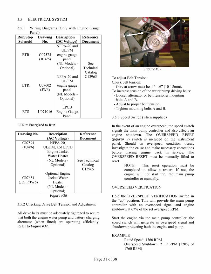
Figure #36 3.5.2 Checking Drive Belt Tension and Adjustment All drive belts must be adequately tightened to secure that both the engine water pump and battery charging alternator (when fitted) are operating efficiently. Refer to Figure #37.
A Figure #37
To adjust Belt Tension: Check belt tension: - Give at arrow must be .4” - .6” (10-15mm). To increase tension of the water pump driving belts:
- Loosen alternator or belt tensioner mounting bolts A and B.
- Adjust to proper belt tension. - Tighten mounting bolts A and B. 3.5.3 Speed Switch (when supplied) In the event of an engine overspeed, the speed switch signals the main pump controller and also affects an engine shutdown. The OVERSPEED RESET (figure# 9) switch is included on the instrument panel. Should an overspeed condition occur, investigate the cause and make necessary corrections before placing engine back in service. The OVERSPEED RESET must be manually lifted to reset.
NOTE: This reset operation must be completed to allow a restart. If not, the engine will not start thru the main pump controller or manually.
OVERSPEED VERIFICATION Hold the OVERSPEED VERIFICATION switch in the “up” position. This will provide the main pump controller with an overspeed signal and engine shutdown at 67% of the set overspeed RPM. Start the engine via the main pump controller; the speed switch will generate an overspeed signal and shutdown protecting both the engine and pump. EXAMPLE Rated Speed: 1760 RPM
Overspeed Shutdown: 2112 RPM (120% of 1760 RPM)
A
B
B
Page 32 of 38
Verification Shutdown: 1410 RPM (67% of 2112 RPM)
CAUTION-after verification of overspeed, lift the OVERSPEED RESET switch and reset the main pump controller to re-instate normal operation of the engine and speed switch.
3.5.4 Magnetic Pick-Up (when supplied)
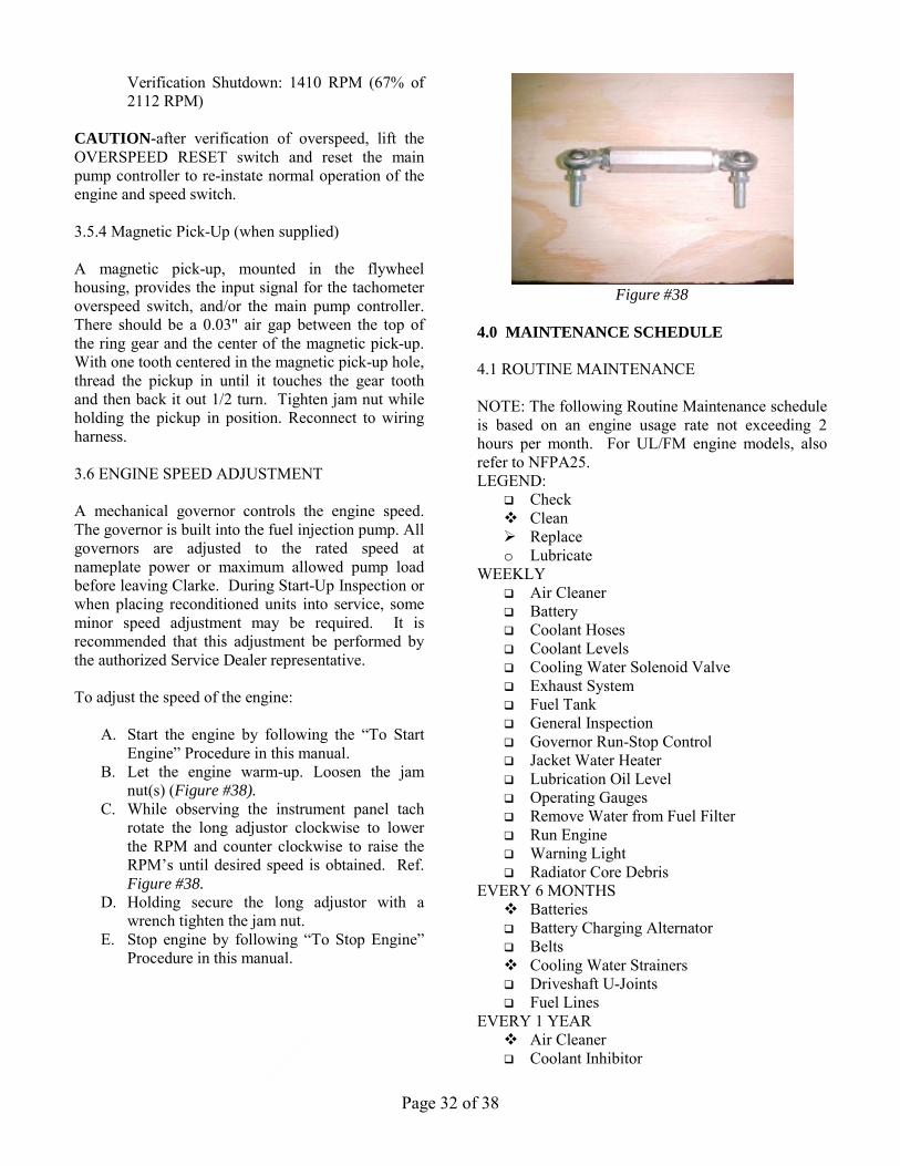
A magnetic pick-up, mounted in the flywheel housing, provides the input signal for the tachometer overspeed switch, and/or the main pump controller. There should be a 0.03" air gap between the top of the ring gear and the center of the magnetic pick-up. With one tooth centered in the magnetic pick-up hole, thread the pickup in until it touches the gear tooth and then back it out 1/2 turn. Tighten jam nut while holding the pickup in position. Reconnect to wiring harness. 3.6 ENGINE SPEED ADJUSTMENT A mechanical governor controls the engine speed. The governor is built into the fuel injection pump. All governors are adjusted to the rated speed at nameplate power or maximum allowed pump load before leaving Clarke. During Start-Up Inspection or when placing reconditioned units into service, some minor speed adjustment may be required. It is recommended that this adjustment be performed by the authorized Service Dealer representative. To adjust the speed of the engine:
A. Start the engine by following the “To Start Engine” Procedure in this manual.
B. Let the engine warm-up. Loosen the jam nut(s) (Figure #38).
C. While observing the instrument panel tach rotate the long adjustor clockwise to lower the RPM and counter clockwise to raise the RPM’s until desired speed is obtained. Ref. Figure #38.
D. Holding secure the long adjustor with a wrench tighten the jam nut.
E. Stop engine by following “To Stop Engine” Procedure in this manual.
Figure #38
4.0 MAINTENANCE SCHEDULE 4.1 ROUTINE MAINTENANCE NOTE: The following Routine Maintenance schedule is based on an engine usage rate not exceeding 2 hours per month. For UL/FM engine models, also refer to NFPA25. LEGEND:
� Check � Clean � Replace o Lubricate
WEEKLY � Air Cleaner � Battery � Coolant Hoses � Coolant Levels � Cooling Water Solenoid Valve � Exhaust System � Fuel Tank � General Inspection � Governor Run-Stop Control � Jacket Water Heater � Lubrication Oil Level � Operating Gauges � Remove Water from Fuel Filter � Run Engine � Warning Light � Radiator Core Debris
EVERY 6 MONTHS � Batteries � Battery Charging Alternator � Belts � Cooling Water Strainers � Driveshaft U-Joints � Fuel Lines
EVERY 1 YEAR � Air Cleaner � Coolant Inhibitor

Page 33 of 38
� Crankcase Vent System o Driveshaft U-Joints � Fuel & Oil Filters � Heat Exchanger Electrode � Lubricating Oil � Mounting Isolators � Wiring System
EVERY 2 YEARS � Air Cleaner � Batteries � Belts � Coolant Hoses � Coolant
IMPORTANT: Set main pump controller to “OFF” while servicing engine. Before turning the main pump controller to the "OFF" position, check with the maintenance and security supervisors to verify that all the departments concerned will be alerted of the temporary interruption of their fire protection equipment for normal maintenance or testing. Also, alert the local fire department in the event that the main pump controller is connected by silent alarm to headquarters. When servicing is complete, return main pump controller selector to "Automatic" position and the mode selector on the engine to “Automatic” position. Advise the appropriate personnel the engine has been returned to the “Automatic”. 5.0 TROUBLE SHOOTING Consult Clarke Service Dealer or Factory. Service dealers can be located by going to our website: www.clarkefire.com. 6.0 PARTS INFORMATION 6.1 SPARE PARTS To ensure best operation and efficiency of all engine components, always use genuine Clarke spare parts. Orders should specify:
• Engine Model Number - See Engine General • Engine Serial Number - Specification • Part Number(s) Refer to Engine Maintenance
Parts List section 6.2 or Parts Illustration in Technical Bulletin in C13886.
Contact numbers for spare parts: • www.clarkefire.com • Phone USA: (513) 719-2352 (calling within USA)
• Phone UK: (44) 1236 429946 (calling outside USA) • Fax USA: (513) 771-0726 (calling within USA) • Fax UK: (44) 1236 427274 (calling outside USA) • E-Mail USA: [email protected] • E-Mail UK: [email protected] 6.2 ENGINE MAINTENANCE PARTS LIST
ENGINE MODEL
OIL
FILTER
FUEL FILTER
PRIMARY
FUEL FILTER
SECONDARY
AIR
FILTER JU4R-UF09 JU4H-UF10 JU4R-UF11 JU4H-UF12 JU4R-UF19 JU4H-UF20 JU4R-UF21 JU4H-UF22 JU4H-UF28 JU4H-UF30 JU4H-UF32 JU4H-UF40 JU4R-UF40 JU4H-UF42 JU4R-UF49 JU4H-UF50 JU4R-UF51 JU4H-UF52 JU4H-UF58 JU4H-UFH2 JU4H-UFH8 JU4H-UFH0 JU4H-AP50
C04440 or
RE59754
C02359 or
RE60021
C03249
JU4R-UF13 JU4H-UF14 JU4R-UF23 JU4H-UF24
C04521 or
RE504836
C02549 or
RE62418
C03249
JU4H-LP20 JU4H-LP50
C04440 or
RE59754
C02533
C03249
JU4H-LP24 JU4H-LP54
C04521 or
RE504836
C02533
C03249
JU4H-UF34 JU4H-UF44 JU4H-UF54
JU4R-UF53 JU4H-UF84 JU4H-AP54
C04521
or RE504836
C02550
or RE520842
C03249
JU6H-UF30 JU6H-UF32 JU6H-UF50 JU6H-UF52 JU6H-UF58 JU6H-UF62 JU6H-UF68 JU6H-UF60 JU6H-UFD0 JU6H-UFG8 JU6H-UFM8 JU6H-UFM0 JU6H-UFD2 JU6H-UFM2 JU6H-AP30 JU6H-AP50 JU6H-AP60
C04440 or
RE59754
C02359 or
RE60021
C03396
JU6H-LP50 JU6H-LP60
C04440 or
RE59754
C02533
C03396

Page 34 of 38
JU6H-LP54 JU6H-LP84
C04521 or
RE504836
C02533
C03396
JU6H-UF34 JU6H-UF54 JU6H-UF84 JU6H-AP34 JU6H-AP54 JU6H-AP84
C04521
or RE504836
C02550
or RE520842
C03396
JW6H-UF30 JW6H-UF38 JW6H-UF40 JW6H-UF48 JW6H-UF50 JW6H-UF58 JW6H-UF60 JW6H-AP30 JW6H-AP40 JW6H-AP50 JW6H-AP60
RE57394
RE508633
AR86745
C03244
ENGINE MODEL Air Filter
Service Kit Air Filter Oil
All 99-55050 C121157 Figure #39
7.0 OWNER ASSISTANCE Consult Clarke Service Dealer or Factory. Service Dealers can be located by going to our website: www.clarkefire.com. 8.0 WARRANTY 8.1 GENERAL WARRANTY STATEMENT The satisfactory performance of Clarke engines and the goodwill of owners / operators of Clarke engines are of primary concern to the Engine Manufacturer, the Engine Service Dealer and Clarke. All provide support of these products after final installation of the complete fire pump and sprinkler system. Warranty responsibility involves both Clarke and the John Deere service organizations worldwide. The Engine Manufacturer (John Deere) provides Warranty for the basic engine components and Clarke provides warranty on the accessories added to meet the NFPA-20 specifications and FM/UL certification requirements. 8.2 CLARKE WARRANTY All Clarke warranted components have warranty duration of 12 months beginning at the Start-up date of the fire pump system. The warranty coverage includes replacement of the part and reasonable cost of labor for installation. Components failed due to
improper engine installation, transportation damage, or misuse is not covered under this warranty. For additional warranty details, see the specific warranty statement “John Deere New Engine Warranty” on the following page. Also contact Clarke direct if you have any questions or require additional information. Clarke is not responsible for incidental or consequential costs, damage or expenses which the owner may incur as a result of a malfunction or failure covered by this warranty. 8.3 JOHN DEERE WARRANTY Warranty Duration Unless otherwise provided in writing, John Deere* makes the following warranty to the first retail purchaser and each subsequent purchaser (if purchase is made prior to expiration of applicable warranty) of each John Deere new off-highway engine marketed as part of a product manufactured by a company other than John Deere or its affiliates: • 12 months, unlimited hours of use, or • 24 months and prior to the accumulation of 2000 hours of use; and on each John Deere engine used in an off-highway repower application: •12 months, unlimited hours of use. Note: In the absence of a functional hourmeter, hours of use will be determined on the basis of 12 hours of use per calendar day. (*John Deere” means Deere Power Systems Group with respect to users in the United States, John Deere Limited with respect to users in Canada, and Deere & Company or its subsidiary responsible for marketing John Deere equipment in other counties where the user is located) Warranty Coverage This warranty applies to the engine and to integral components and accessories sold by John Deere. All John Deere-warranted parts and components of John Deere engines which, as delivered to the purchaser, are defective in materials and/or workmanship will be repaired or replaced, as John Deere elects, without charge for parts or engine repair labor, including reasonable costs of labor to remove and reinstall non engine parts or components of the
Page 35 of 38
equipment in which the engine is installed, and, when required, reasonable costs of labor for engine removal and reinstallation, if such defect appears within the warranty period as measured from the date of delivery to the first retail purchaser, if the delivery is reported to John Deere within 30 days of the delivery. Emissions Warranties Emissions warranties appear in the operation and maintenance instructions furnished with the engine/machine. Obtaining Warranty Service Warranty service must be requested of the nearest authorized John Deere engine service outlet before the expiration of the warranty. An authorized service outlet is a John Deere engine distributor, a John Deere engine service dealer, or a John Deere equipment dealer selling and servicing equipment with an engine of the type covered by this warranty. Authorized service outlets will use only new or remanufactured parts or components furnished or approved by John Deere. Authorized service locations and the name of the John Deere division or subsidiary making this warranty are listed in the Parts and Service Directory for John Deere Engines. At the time of requesting warranty service, the purchaser must be prepared to present evidence of the date of delivery of the engine. John Deere reimburses authorized service outlets for limited travel expenses incurred in making warranty service repairs in non-John Deere applications when travel is actually per formed. The limit, as of the date of publication of this statement, is US $300.00 or equivalent. If distances and travel times are greater than reimbursed by John Deere, the service outlet may charge the purchaser for the difference. Warranty Exclusions John Deere’s obligations shall not apply to fuel injection pump and nozzles during the pump and nozzle manufacturer’s warranty period on the pump and nozzles, components and accessories which are not furnished or installed by John Deere, nor to failures caused by such items. When the pump manufacturer’s warranty is less than the engine
warranty, John Deere will reimburse pump repair costs for warrantable-type failures during the remainder of the original engine warranty period, when so documented by the pump manufacturer’s approved service outlet. Purchaser’s Responsibilities The cost of normal maintenance and depreciation. Consequences of negligence, misuse, or accident involving the engine, or improper application, installation, or storage of the engine, or improper application, installation, or storage of the engine. Consequences of service performed by someone other than a party authorized to perform warranty service, if such service, in John Deere’s judgment, has adversely affected the performance or reliability of the engine. Consequences of any modification or alteration of the engine not approved by John Deere, including, but not limited to, tampering with fuel and air delivery systems. The effects of cooling system neglect as manifested in cylinder liner or block cavitation (“pitting”, “erosion”, “electrolysis”). Any premium for overtime labor requested by the purchaser. Costs of transporting the engine or the equipment in which it is installed to and from the location at which the warranty service is performed, if such costs are in excess of the maximum amount payable to the service location were the warranty service performed at the engine’s location. Costs incurred in gaining access to the engine; i.e., overcoming physical barriers such as walls, fences, floors, decks or similar structures impeding access to the engine, rental of cranes or similar, or construction of ramps or lifts or protective structures for engine removal and reinstallation. Incidental travel costs including tolls, meals, lodging, and similar. Service outlet costs incurred in solving or attempting to solve non-warrantable problems. Services performed by a party other than an authorized John Deere engine service dealer, unless required by law.

Page 36 of 38
Charges by dealers for initial engine start-up and inspection, deemed unnecessary by John Deere when operation and maintenance instructions supplied with the engine are followed. Costs of interpreting or translating services. No Representations or Implied Warranty Where permitted by law, neither John Deere nor any company affiliated with it makes any guaranties, warranties, conditions, representations or promises, express or implied, oral or written, as to the nonoccurrence of any defect or the quality or performance of its engines other than those set forth herein, and DOES NOT MAKE ANY IMPLIED WARRANTY OR CONDITIONS OF MERCHANTABILITY OR FITNESS otherwise provided for in the Uniform Commercial Code or required by any Sale of Goods Act or any other statute. This exclusion includes fundamental terms. In no event will a John Deere engine distributor or engine service dealer, John Deere equipment dealer, or John Deere or any company affiliated with John Deere be liable for incidental or consequential damages or injuries including, but not limited to, loss of profits, loss of crops, rental of substitute equipment or other commercial loss, damage to the equipment in which the engine is installed or for damage suffered by purchaser as a result of fundamental breaches of contract or breach of fundamental terms, unless such damages or injuries are caused by the gross negligence or intentional acts of the foregoing parties. Remedy Limitation The remedies set forth in this warranty are the purchaser’s exclusive remedies in connection with the performance of, or any breach of guaranty, condition, or warranty in respect of new John Deere engines. In the event the above warranty fails to correct purchaser’s performance problems caused by defects in workmanship and/or materials, purchaser’s exclusive remedy shall be limited to payment by John Deere of actual damages in an amount not to exceed the cost of the engine. No Seller’s Warranty No person or entity, other than John Deere, who sells the engine or product in which the engine has been installed makes any guaranty or warranty of its own
on any engine warranted by John Deere unless it delivers to the purchaser a separate written guaranty certificate specifically guaranteeing the engine, in which case John Deere shall have no obligation to the purchaser. Neither original equipment manufacturers, engine or equipment distributors, engine or equipment dealers, nor any other person or entity, has any authority to make any representation or promise on behalf of John Deere or to modify the terms or limitations of this warranty in any way. Additional Information For additional information concerning the John Deere New Off-Highway Engine Warranty, see booklet Engine Owner’s Warranty – Worldwide. 9.0 ATCM CALIFORNIA EMISSIONS REGULATIONS FOR STATIONARY ENGINES NOTICE AND DISCLAIMER FOR STATIONARY COMPRESSION IGNITION ENGINES INSTALLED IN CALIFORNIA AFTER JANUARY 1, 2005
1. This Notice and Disclaimer is an addendum to, and made a part of, Clarke’s Fire Protection Products, Inc.’s (“Clarke”) Standard Terms and Conditions of Sale and, in all respects not inconsistent therewith, also applies to all sales of stationary compression ignition engines installed in California after January 1, 2005.
2. Stationary diesel-fueled compression ignition engines installed in California after January 1, 2005 are subject to California’s Airborne Toxic Control Measure for Stationary Compression Ignition Engines (the “ATCM”), Cal. Code Regs. Title 17, Section 93115. The California Air Resources Board (“CARB”) has reviewed the emissions estimation methodology provided by Clarke Fire Protection Products, Inc. (“Clarke”) and has concluded that Clarke has used a valid methodology for estimating the emissions from engines supplied by Clarke and that the engines presumptively comply with the ATCM’s emissions standards. Clarke’s methodology used existing emissions test data associated with similar engines to estimate the emissions produced by the emergency fire pump engines supplied by Clarke.
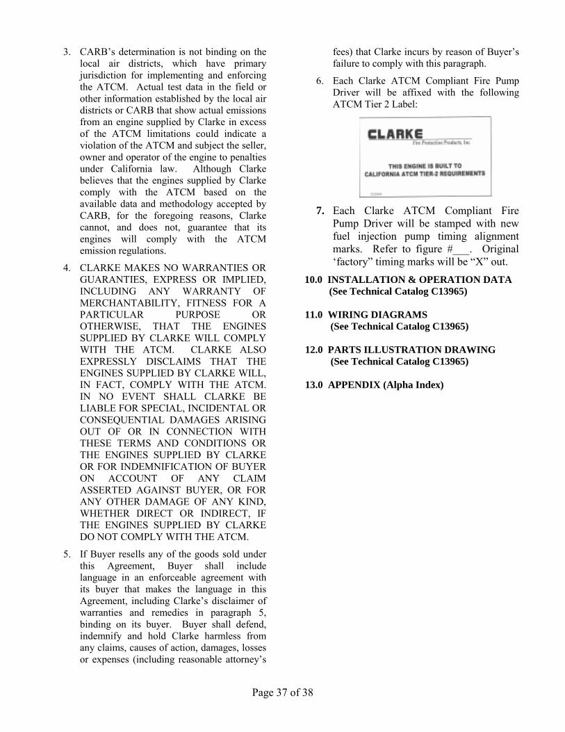
Page 37 of 38
3. CARB’s determination is not binding on the local air districts, which have primary jurisdiction for implementing and enforcing the ATCM. Actual test data in the field or other information established by the local air districts or CARB that show actual emissions from an engine supplied by Clarke in excess of the ATCM limitations could indicate a violation of the ATCM and subject the seller, owner and operator of the engine to penalties under California law. Although Clarke believes that the engines supplied by Clarke comply with the ATCM based on the available data and methodology accepted by CARB, for the foregoing reasons, Clarke cannot, and does not, guarantee that its engines will comply with the ATCM emission regulations.
4. CLARKE MAKES NO WARRANTIES OR GUARANTIES, EXPRESS OR IMPLIED, INCLUDING ANY WARRANTY OF MERCHANTABILITY, FITNESS FOR A PARTICULAR PURPOSE OR OTHERWISE, THAT THE ENGINES SUPPLIED BY CLARKE WILL COMPLY WITH THE ATCM. CLARKE ALSO EXPRESSLY DISCLAIMS THAT THE ENGINES SUPPLIED BY CLARKE WILL, IN FACT, COMPLY WITH THE ATCM. IN NO EVENT SHALL CLARKE BE LIABLE FOR SPECIAL, INCIDENTAL OR CONSEQUENTIAL DAMAGES ARISING OUT OF OR IN CONNECTION WITH THESE TERMS AND CONDITIONS OR THE ENGINES SUPPLIED BY CLARKE OR FOR INDEMNIFICATION OF BUYER ON ACCOUNT OF ANY CLAIM ASSERTED AGAINST BUYER, OR FOR ANY OTHER DAMAGE OF ANY KIND, WHETHER DIRECT OR INDIRECT, IF THE ENGINES SUPPLIED BY CLARKE DO NOT COMPLY WITH THE ATCM.
5. If Buyer resells any of the goods sold under this Agreement, Buyer shall include language in an enforceable agreement with its buyer that makes the language in this Agreement, including Clarke’s disclaimer of warranties and remedies in paragraph 5, binding on its buyer. Buyer shall defend, indemnify and hold Clarke harmless from any claims, causes of action, damages, losses or expenses (including reasonable attorney’s
fees) that Clarke incurs by reason of Buyer’s failure to comply with this paragraph.
6. Each Clarke ATCM Compliant Fire Pump Driver will be affixed with the following ATCM Tier 2 Label:
7. Each Clarke ATCM Compliant Fire
Pump Driver will be stamped with new fuel injection pump timing alignment marks. Refer to figure #___. Original ‘factory” timing marks will be “X” out.
10.0 INSTALLATION & OPERATION DATA (See Technical Catalog C13965)
11.0 WIRING DIAGRAMS
(See Technical Catalog C13965)
12.0 PARTS ILLUSTRATION DRAWING (See Technical Catalog C13965)
13.0 APPENDIX (Alpha Index)

Page 38 of 38
13.0 APPENDIX (Alpha Index) Subject Page
A
ACTM Compliant Engines 35 Air Cleaner 23,31 Alternator 29,30
B Battery Cables 12 Battery Recommendations 12,31 Belt Adjustment 29
C Capacities 27,28 Coolant Recommendations 27,28 Cooling System Anti-Freeze Solutions 27,28 Cooling System Capacity 27 Cooling Water Supply (Loop) 11,14 Cooling Water Flow Requirements * Filling Procedure 28 Heat Exchanger 11,14,31 Inhibitors 27,28,31 Maintenance 31,32 Radiator 11,14,23,31 Water 25 Crankcase Ventilation 24
D Dipstick, Oil Level 25,26 Driveshaft alignment 11 Driveshaft Maintenance 13,31
E Electrical System 29 Engine Models 5 Engine Out of Fuel 11 Engine Protective Systems (overspeed) 30 Engine Start-Up Service 14 Exhaust System 23
F Filters: Air Cleaner 23,31 Fuel 17,31 Lubricating Oil 8,6,31 Fuel Specifications 10,11 Fuel System Operation 17 Bleeding 17 Pump, Injection 4,8,22,23 Pump, Lift 14 Service 13 to 19
G Governor Speed Adjustment 30,31
H Heaters, Engine 11
I Installation Data * Installation Instructions 10
Subject Page
L
Lube Oil Recommendations 27 Lubricating Oil Volume 27 Lubricating System 25
M Magnetic Pickup 30 Maintenance Schedule 31 Manual Operation 14 Model Number Identification 4
N Name Plate (Engine) 4
O Oil Filter 26 Oil Level Dipstick 25 Oil Pressure * Oil Specifications/Recommendations 27 Operation Data * Out Of Fuel Procedures 11 Overspeed Reset 30 Overspeed Verification 30
P Parts Illustrations * Parts Information 31 Preventive Maintenance Schedule 31 Pump: Fuel Injection Pump 4,18,22,23 Fuel Lift Pump 14
S Serial Number 4 Shutdown Systems 30 Specifications: Fuel 11 Lubrication Oil 27 Speed Switch 30 Storage 10
T Technical Data *
W Warranty 32 Wiring Diagram: DC System 29* AC Heater Systems 29* * See Technical Catalog C13965