OPERATION AND MAINTENANCE COST DATA FOR RESIDENTIAL ...
107
Report No. DOE/JPL 955614-80/1 DjstributionCateo rv UC-63 I JPL NO. 9950-408 OPERATION AND MAINTENANCE COST DATA FOR RESIDENTIAL PHOTOVOLTAIC MODULES/PANELS LOW-COST SOLAR ARRAY PROJECT ENGINEERING AREA FINAL REPORT JULY 1980 The JPL Low-Cost Solar Array Project is sponsored by the U S Department of Energy and forms part of the Solar Photovoltaic Conversion Program to initiate a major effort toward the development of low cost solar arrays This work was performed for the Jet Propulsion Laboratory California Institute of Technology by agreement between NASA and DOE Prepared for / Jet Propulsion Laboratory IZ') " Pasadena, California 91103 (- (NASA.-CR-163585) OPERATION AND MAINTENANCE N80-32855 vV COST DATA FOR RESIDENTIAL PHOTOVOLTAIC y MODULES/PANELS Final Report (Bart, Hill, Kosar, Rittleman, and) 106 p HC A06/MF A01 Unclas CSCL 10A G3/44 28880 By Research and Solar Applications Division BURT HILL KOSAR RITTELMANN ASSOCIATES 400 Morgan Center Butler. Pennsylvania 16001
Transcript of OPERATION AND MAINTENANCE COST DATA FOR RESIDENTIAL ...

Report No DOEJPL 955614-801 DjstributionCateo rv UC-63 I JPL NO 9950-408
OPERATION AND MAINTENANCE COST DATA FOR
RESIDENTIAL PHOTOVOLTAIC MODULESPANELS
LOW-COST SOLAR ARRAY PROJECT ENGINEERING AREA
FINAL REPORT
JULY 1980
The JPL Low-Cost Solar Array Project is sponsored by the U S Department of Energy and forms part of the Solar Photovoltaic Conversion Program to initiate a major effort toward the development of low cost solar arrays This work was performed for the Jet Propulsion Laboratory California Institute of Technology by agreement between NASA and DOE
Prepared for
Jet Propulsion Laboratory IZ) Pasadena California 91103 (shy
(NASA-CR-163585) OPERATION AND MAINTENANCE N80-32855 vV COST DATA FOR RESIDENTIAL PHOTOVOLTAIC yMODULESPANELS Final Report (Bart Hill Kosar Rittleman and) 106 p HC A06MF A01 Unclas
CSCL 10A G344 28880
By
Research and Solar Applications Division BURT HILL KOSAR RITTELMANN ASSOCIATES
400 Morgan Center Butler Pennsylvania 16001
Report No DOEJPL 955614-801 Distribution Category UC-63
OPERATION AND MAINTENANCE
COST DATA FOR RESIDENTIAL PHOTOVOLTAIC MODULESPANELS
JPL CONTRACT NO 955614
LOW-COST SOLAR ARRAY PROJECT ENGINEERING AREA
FINAL REPORT
JULY 1980
The JPL Low-Cost Solar Array Project is sponsored by the US Department of Energy and forms part of the Solar Photovoltaic Conversion Program to initiate a major effort toward the development of low-cost solar arrays This work was performed for the Jet Propulsion Laboratory California Institute of Technology by agreement between NASA and DOE
Prepared for
Jet Propulsion Laboratory Pasadena California 91103
by
BURT HILL KOSAR RITTELMANN ASSOCIATES 400 Morgan Center
Butler Pennsylvania 16001
This report was prepared as an account of work sponsored by the United
States Government Neither the United States nor the United States
Department of Energy nor any of their employees nor any of their
contractors subcontractors or their employees makes any warranty express
or implied or assumes any legal liability or responsibility for the
accuracy completeness or usefulness of any information apparatus product
or process disclosed or represents that its use would not infringe
privately owned rights
STAFF
The following persons at Burt Hill Kosar Rittelmann Associates were
responsible for the production of this Document
J R Oster Jr Project Manager
D R Zaremski Jr Principle Investigator
E M Albert Report Production
S L Hawkins Report Production
ACKNOWLEDGEMENTS
Russell Sugimura of the Jet Propulsion Laboratory was the Technical Monitor
for this study and Ronald C Ross Jr is the Task Manager of the
Engineering area of the Low-Cost Solar Array (LSA) Project for which this
study was performed
ii
ABSTRACT
Burt Hill Kosar Rittelmann Associates has conducted a study to identify and
estimate costs associated with the operation and maintenance of residential
photovoltaic modules and arrays
Six basic topics related to operation and maintenance to photovoltaic
arrays were investigated - General (Normal) Maintenance Cleaning Panel
Replacement Gasket RepairReplacement Wiring RepairReplacement and
Termination RepairReplacement The effects of the mounting types - Rack
Mount Stand-Off Mount Direct Mount and Integral Mount - and the
installationreplacement type - Sequential Partial Interruption and
Independent - have been identified and described Recommendation on
methods of reducing maintenance costs have been made
iii
CONTENTS
SECTION PAGE
1 SUMMARY 1-1
2 INTRODUCTION 2-1
21 TERMINOLOGY AND DEFINITIONS 2-2
22 COST BASIS 2-5
23 UNITS 2-6
3 CHARACTERISTICS OF MAINTENANCE 3-1
31 CHARACTERISTICS OF RESIDENTIAL MAINTENANCE 3-3
32 CHARACTERISTICS OF RESIDENTIAL MAINTENANCE
RELATIVE TO PHOTOVOLTAICS 3-5
4 PANELARRAY DESIGN 4-1
41 PANELARRAY MOUNTING TYPE 4-1
42 INSTALLATIONREPLACEMENT TYPE 4-6
43 PANELARRAY DETAILS 4-8
5 OPERATIONMAINTENANCE 5-1
51 GENERAL (NORMAL) MAINTENANCE 5-2
52 CLEANING 5-9
53 PANEL REPLACEMENT 5-15
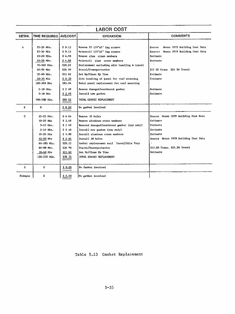
54 GASKET REPAIRREPLACEMENT 5-32
55 WIRING REPAIR 5-36
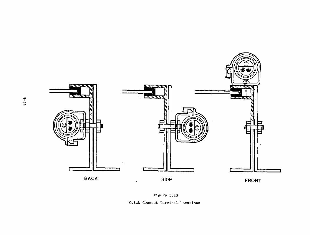
56 TERMINATION REPAIR 5-40
6 REPAIRREPLACEMENT STRATEGY 6-1
7 CONCLUSIONS 7-1
8 RECOMMENDATIONS 8-1
9 NEW TECHNOLOGIES 9-1
10 BIBLIOGRAPHY i 10-1
iv
SECTION I
SUMMARY
This report presents the results of a study conducted by Burt Hill Kosar
Rittelmann Associates The objective of this study was to identify and
estimate costs associated with the operation and maintenance of residential
photovoltaic modules and arrays The approach used in accomplishing this
objective was to identify the potential problems associated with
photovoltaic modules and arrays identify and describe the corrective
procedures related to these problems identify and estimate costs to
perform the corrective procedures to identify the cost drivers relative to
the specified OampM procedures and to recommend where possible potential
techniques and procedures for the reduction of operation and maintenance
procedures
The costs associated with maintenance procedures will vary greatly with
strong dependencies on
The characteristics of maintenance in general
Panelarray mounting type
Installationreplacement type
Panelarray detail
In the residential sector the owner is the principal charged with the
responsibility of maintenance Specific maintenance procedures can be
carried out by the owner or an individual contracted by the owner who
specializes in a maintenance task Typically the homeowner performs only
the simplest of maintenance tasks and seeks the expertise of a more
qualified individual to perform the more detailed and technical tasks
1-1
As a result most maintenance procedures relative to photovoltaic arrays
will be carried out by professionals This will of course result in higher
operation and maintenance costs
The four basic generic mounting types as identified in the Residential
Photovoltaic Module and Array Requirement Study Report No DOEJPL 955149
- 791 are described and their affect on maintenance procedures and costs
are characterized These mounting types are
Rack Mount
Standoff Mount
Direct Mount
Integral Mount
Each of these mounting types impose certain restrictions relative to
maintenance operations For example the following installation
replacement types have been identified and investigated
Sequential
Partial Interruption
Independent
The photovoltaic systems designer must perform a detailed optimization
relative to initial costs operation and maintenance costs and the expected
life of the system This optimization must be performed while keeping in
mind the strong influence aesthetic considerations dictate in residential
design
1-2
Six basic topics pertaining to the operation and maintenance of
photovoltaic arrays were investigated in this study These tasks include
General (normal) maintenance
Cleaning
Panel replacement
Gasket repairreplacement
Wiring repairreplacement
Termination repairreplacement
It is important to note that the costs generated in this study are detail
and site specific and care must be used when attempting to determine the
applicability of these numbers relative to a manufacturers specific panel
detail
As residential homeowners are not likely to be involved in typical
maintenance operations the array must be designed to minimize owner
involvement Likewise it is necessary that the photovoltaic array be
designed to minimize all maintenance operations in order to keep the life
cycle cost to a minimum
Of the above mentioned maintenance procedures cleaning is likely to be
performed on a fairly regular basis However it appears that professional
cleaning should not be performed more than once a year unless the array
degradation is severe as a result of dirt retention The only other
maintenance category which is likely to add significantly to the operation
1-3
and maintenance costs during the life of the array is panel replacement
This cost is very sensitive to panel edge and mounting details and extreme
efforts must be taken to minimize the costs associated with replacement if
the modules are prone to permanent damage
Finally all components of the photovoltaic module and array must be
designed to be maintenance-free and have a design life of 20 years To
accomplish this care must be taken in the choice of materials and a design
optimization must include a detailed evaluation of the need for and the
associated costs of maintenance
1-4
SECTION 2
INTRODUCTION
This final report documents a study of operation and maintenance procedures
and associated costs for photovoltaic modules panels and arrays used in
residential applications The study was performed by Burt Hill Kosar
Rittelmann Associates for the engineering area of the Jet Propulsion
Laboratories Low-Cost Solar Array Project under contract No 955614 as a
part of the US Department of Energy Solar Photovoltaic Conversion
Program
The primary emphasis of the study was on costs associated with the
maintenance of the photovoltaic module panel and array in residential
applications The types of maintenance required includes such items as
panel replacement wire replacement cleaning and generalroutine
servicing The maintenance procedures which will be performed are a direct
result of the type of problem and the restrictions imposed by the nature of
the application ie the general lack of residential owners involvement
in the maintenance and repair of his house and its systems
The direct objectives of this study were
Identify potential operation problems which may surface during the life
of the photovoltaic array
Identify proper maintenance procedures for the previously
identified operation problems
Establish maintenance procedure costs
Identify major cost drivers and methods for reduction of costs assoshy
ciated with maintenance procedures
2-1
The approach used in accomplishing these objectives was to first identify
the potential problems that may be encountered during the operational life
of the PV array to investigate the nature of the residential ownerss
participation in the general maintenance of his home to establish typical
maintenance procedures which can be used to solve the typical problems
which have been previously identified and finally to determine the costs
associated with these maintenance procedures In order to complete the
study the major cost drivers corresponding to the maintenance procedures
were identified and where possible methods of reducing these costs have
been recommended The results of that effort are presented in this final
report
21 TERMINOLOGY AND DEFINITIONS
Terminology used in the final report are illustrated in Figure 1 These
come from the preliminary set of photovoltaic terminology and definitions
established in 1978 by members of the Photovoltaics Program The term
Residential Photovoltaic Power System was not in the original definition
but is provided for completeness
Also the following definitions are included for use in this report
Durabilityor Useful Life Durability is the average expected service life
of components with a specified maintenance program taking into account the
cost of maintaining the component at an acceptable performance level and
the cost of replacing the component At the point in time where the cost
of the maintenance program exceeds the cost of replacement the service
life of that component has been exceeded Reliability is the probability
that a component will perform under stated conditions its intended
function for a specified period of time
2-2
-- ----
SOLAR CELL ------
SOLAR CELL--THE BASIC PH-OTOVOLTAIC 1 DEVICE WHICH GENERATES ELECTRICITY
WHEN EXPOSED TO SUNLIGHT
MODULE--THE SMALLEST COMPLETE IL------
ENVIRONMENTALLY PROTECTED ASSEMBLY I
OF SOLAR CELLS AND OTHER COMPONENTS (INCLUDING ELECTRICAL TERMINATIONS) DESIGNED TO GENERATE DC POWER WHEN MODULE
UNDER-UNCONCENTRATED TERRESTRIAL SUN-LIGHT
PANEL--A COLLECTION OF ONE OR MORE MODULES FASTENED TOGETHER FACTORY PREASSEMBLED AND WIRED FORMiNG A FIELD INSTALLABLE UNIT
ARRAY--A MECHANICALIY INTEGRATED ASSEMBLY OF MODULES TOGETHER WITH SUPPORT STRUCTURE AND OTHER COMPONENTS ARRAY AS REQUIRED TO FORMA FIELD INSTALLED DC POWER PRODUCING UNIT BRANCH
CIRCUIT
PARALLELED MODULES CONNECTED IN SERIES TO PROVIDE DC POWER AT THE SYSTEM VOLTAGE LEVEL
PHOTOVOLTAIC SPOWER SYSTEM
RESIDENTIAL PHOTOVOLTAIC POWER SYSTEM--THE AGGREGATE OF ALL BRANCH CIRCUITS I (ARRAY(S)) TOGETHER WITH AUXILIARY SYS- II TEMS (POWER CONDITIONING WIRING PRO- I---- -TECTION CONTROL UTILITY INTERFACE) AND IUTILITY FACILITIES REQUIRED TO CONVERT TERRESTRIAL
I POWER DISTRIBUTIONSUNLIGHT INTO ELECTRICAL ENERGY SUITABLE FOR CONNECTION TO A RESIDENCES ELECTRICAL DISTRIBUTION SYSTEM ORA
POWERUTILITY ELECTRIC POWER GRID CONDITIO NERj
ELECTRICAL APPLIANCESB ]
Figure 21 Residential Photovoltaic System Terminology
2-3
Serviceability Serviceability is a measure of the degree to which
servicing the component can be accomplished under specified conditions
within a given amount of time Servicing is the performance of operations
intended to sustain the intended operation of the component this includes
such items as painting and inspecting for mechanical and electrical
integrity but does not include periodic replacement of parts or any
corrective maintenance tasks
Maintainability Maintainability is a design and installation charactershy
istic indicating the degree of ease with which a component can be restored
to its proper operation condition Maintainability is generally stated as
the quantity of time required to restore or repair failures
Periodic Maintenance Periodic maintenance is the action of performing
normal maintenance procedures on a systematic basis by scheduling service
and replacement of components in order to maintain performance or prevent
failure
Preventive Maintenance Preventive maintenance programs are planned
procedures designed to retain a price of equipment or a component at a
specified level of performance
Corrective Maintenance Corrective maintenance is an action taken as a
result of failure in order to return an item to a specified level of
performance
Accessibility Accessibility is the quality or state of being easy to
access
Repairability Repairability is the quality or state of being easy to
repair
2-4
Cleanability Cleanability is the quality or state of being easy to
clean
22 COST BASIS
Costs presented in the final report are expressed in 1980 constant dollars
unless stated otherwise Costs were developed in first quarter 1979
dollars and converted to constant 1980 dollars by use of a price inflater
117
Two major sources of costing information were used
1 Engelsman Coert 1979 Residential Cost Manual Van Nostrand
Reinholt Company New York New York 1979
2 1979 Means Cost Data File Robert Snow Means Company Inc Duxbury
Massachusetts 1979
The labor costs used throughout this report represent averaged values
obtained by investigating the costs throughout the country of specific
labor group specialists These numbers are inclusive of general and
administrative and overhead costs but do not reflect profit Table 1 an
index to geographical area conversion tables for quoted labor costs can be
used to more accurately reflect the maintenance costs for specific
locations throughout the country
2-5
23 UNITS
Despite attempts to change it the residential construction industry
remains rooted in the English system of units It is not anticipated that
the conversion of the industry to SI units will be easy or painless
Rather than indiscriminantly convert all measurements to SI units it was
decided to leave the English units as best representative of the industry
today
2-6
ROOFINGand SIDIGN LABOR LABOR LABOR LABOR ROOFING and SIDING LABOR LABOR LABOR LABOF Wter and manpprooflng etc UUOAA
AlA RURA ARIA
U8N ARIA
RURAL ARIA
Water and flmpprnofing etc URBAN ARIA
RURAL AR1A
URBAN ARIA
IUAA ARiA
ALABAMA
ALASKA
ARIZONA
Birmingham MobileHontooery
Anohoa Fairbanks Phunenlx
66 7066
I 40 I 40
79
63 6864
1 33 1 33
75
INDIANA
IZWA
EvAnsville tort WayneGary Indianapolis South Bend
Council BlutffDavenport
76 7599 96 77
7406
73 7296 82 74
783
NEW HAMPSFIIREHanchester
ia JERSEY Atlantic City Camden Govr Jersey City Long IrunchMount holly
54
92 08
I 00 1 00
9997
52
89 I 04
97 I 03 9694
BROIL ISLAND Providence
SOUll CAROLINA Charleston Columbia GreenvilIe
SOUTHIDAKOTA Rapid CitySioUX PalB
85
46 46 46
7675
01
44 44 44
i71
Tucson 82 79 Des dones 72 68 liewark I 00 95
A R IANSAS Fort Smith
Littlelock 68 68
66 65
KANSAS
DubuqueSioo City Topeho
65 83 79
62 61 76 04EV O4CICO
Toms River Trenton VinelundAlbuquerque
99 97 9261
96 92 8958
TEiNNESSEE ChattanoogaKnoxville Memphisflashvllle
60 S 7362
66 56 6959
CALIFORNIA Fretno 97 94 WIcht 68 65 Clovi 49 47
Ou AndOaklandSacramento hSanDego
San FrAncisco
I 041 06I 04 I 06 I 06
0
991 01I 00 I 02 I 01
KENTUGKV
LOUISIANA
DoNTln9 GreenLexington LOuCISVlIc Baton Rouge
646 68 71
6266 65 69
NEW YORK
Las Cruces Santa Fe
AIbanyRioghnaston aufflao
49 46
I576 99
47 44
8373 85
TEXAS Amarillo DallasEl Paso Fort NorthIlousion San AnIUnlo
45 6947 6771 0
43 6645 567 4
COLORADO Colorado Springs 75 71 New Orleans 75 72 Hineolat t I I 3 Ao
COtllECTI Ci
Denver
8r dgeputtHartford New haven
00
85 85 OS
76
82 1 92
OARlanoor
Shreveport
d0 Portland
69
60
6
58 57
New York City RIverhead L Rochester Syrause White Plains
109 I 0 92
97 I DI
| 03 1 04 89 94 96
UTAH
VERMONT
VIRGINIA
Salt Lake City
Burlington
NewPort News
76
79
46
77
75
44
OEIAWAkE Dover Wilmington
68 1 01
66 96
MARYLAND AnnapolisBaltimore
69 11
66 67
NORTH
Yonkers
CAROLINA Asheville
I 01
46
96
44
NorfoIk Richmond Roanoke
46 46 46
44 44 44
O C
P6081DA
Washington
tort taudtrdale
79
77
74
73
MASSACHUSETTS BostonSpringfield Worceotar
90 as 82
9682 79
CharlotteGreensboro Raleigh
4748 49
446 46
WASHIINGTONI SLntle Spokane
80 77
76 74
Jacksonville Plami Pensacola
tlhlcsee
70 1 I 70 70
67 1 O5 67 68
HILIIIGAN Detroit Flint Grand Rapids Ianstng
I 00 93 60 78
95 90 58 75
NORTl DAKOTA Blsmarb Fargo Minot
6)61 61
59 5 59
WCST VIRGINIA
WISCONSIN
CharleSton Huntington
Madion
83 79
76
19 75
73 I paW st Palm Beach 7277 68 IONESIFA74KtnaolMINEOT DuluthD1uhlluth 63 7g Oio Akron 895 86 11ilwaukce 89 72
GLOIGIA 1
Atlanta 59 4anA54
56 46 MISSISSIPPI
Hihaeayolii
Jackson
94
62
all
60
Clilcinoatl1 Cleveland Colunhus Dayton
94 I 02 99 87
89 97 96 83
HYDNIaG Casper CheyennL
71 75
b9 71
iAI[AII 1I11l Ilonolulu
9797 9492
MISSOURI Kansas CitySp Inglild 8364 9062 ToledoYoungstown I O92 9789 CANADA
1GARB1
ILLINOIS
Boise Pncatello
Chi1agoBe t u 8
M e1 t u r
66 70
996
6
65 60
94 8
8 3
MONTANA
N E R S A
St toniS
Billing Butte Great Fallo I i c n6
82
66 66 69
65
70
94 63 67
OKLAHUHA
ORECON
P E NNHS L YA NIIA
Oklahoma CItyCity
E ene Portland r e
77 77 77 )786
i s
733 4 74 82 7 6
CaIgary Alboto
Montreal uebLc Ottawo Ontario Quebec Quebec Toronto OntarioVA n u ver Br itish C o lu mb ia
77
0l 60 70 934
14
7 CS 67 A86 2
IG 0
PolneordI-okod
SprIngfield i-
8656885 92
82K8282
89 NEVADA
nohlNorthOaha
Las Vegas eo9Reno
55it74 94
94
53 70
09 9Scranton89
iiarrioburgPhiladelphiapitbug1
Pittsborh
84 I 030PB
1 02 00
80 9997
97 7)
Winnipeg Manitoba 64 62
Table 21
SECTION 3
CHARACTERISTICS OF MAINTENANCE
Maintenance is the general servicing repair or replacement of a component
system or piece of equipment There are basically two phases of any
maintenance program Preventative and corrective maintenance
Preventative maintenance programs are planned and scheduled procedures
which are inacted to retain a component at a specified performance level
This may be accomplished by providing systematic inspections for the
detection and prevention of inpending failures A preventative maintenance
plan for equipment or systems should minimize the frequency and difficulty
of servicing while providing maximum performance and prolonged life
These preventive maintenance programs should be established by the
manufacturers of the systems components
Corrective maintenance programs are procedures performed as a result of
failure in order to restore a component or system to its designed level of
performance Tasks included in such programs include testing failure
isolation and repairreplacement
Should an owner determine not to implement a planned maintenance program
then the equipment will operate until it fails This is however not a
recommended approach If a general maintenance program is not adhered to
it is recommended that any safety devices in the system be periodically
inspected to insure operability
All maintenance programs include to some degree the following
1 Management maintenance policy which consists of the objectives and
type of maintenance program the personnel required organization
performance schedules and cost information
3-1
2 Records of the systems systems components and associated equipment
including
a Construction drawings and specifications
b As-built drawings
c Shop drawings and equipment catalogs
d Servicing instructions maintenance instructions troubleshooting
checklists and spare parts lists
e Service and spare parts sources
f Systems diagrams
3 Procedures and Schedules This is the most important part of the
maintenance program and relates to the operation inspection servicing
repairing and replacement of components and equipment At a minimum it
includes the following requirements
a Operating instructions
1 Starting and shutdown procedures
2 Seasonal adjustments
3 Logging and recording
b Inspection
1 That equipment to be inspected
2 Points of inspection
3 Time of inspection
4 Methods of inspection
5 Evaluation recording and reporting
c Service and repair
1 Frequency of service
2 Service procedures
3 Repair procedures
4 Reporting
3-2
Operating and maintenance manuals 5 Operating and Maintenance Manuals
systemprovide instructions and information pertaining to the overall
These manuals should be prepared by the system designer in conjunction
with andor including the component manufacturers appropriate
preventive procedures shouldmaintenance information All maintenance
to perform the necessarybe included with adequate information
maintenance actions should also beprocedures Required routine
included in the maintenance manual and are typically incorporated on a
permanent label attached to the equipment However this label may
merely indicate the required procedure which is more greatly explained
in the operation and maintenance manual
two partsThe operation and maintenance manual can be organized in
with Part I containing information on the system and Part II covering
the equipment components in the overall system
31 CHARACTERISTICS OF RESIDENTIAL MAINTENANCE
In the residential sector the owner is the principal charged with the
It is the owners responsibility toresponsibility of maintenance
for his residence a broad sense the maintenance programestablish in
His policy will determine
a What type of maintenance program to adopt
onWhether to provide for operation and maintenance by contract orb
his own
3-3
The housing sector consists of two categories -- single family and
multi-family dwellings Within each of these categories the residence can
be owned or rented In general the players involved in the maintenance
tasks will be different for the two categories of dwellings and the two
owner types
Briefly single family dwellings which are rented and multi-family
dwellings which are rented or owned will be maintained under contract or
by arrangement between the owners and a qualified maintenance person In
the case of apartments townhouses and condominiums a general maintenance
person is typically on staff and is capable of performing general
maintenance and in some instances more difficultspecialized maintenance
procedures The costs for these operations when performed by an on-staff
maintenance person will be different than those outlined in this report
Investigation of the estimated US housing inventory may be a good general
indicator of the likelihood of which maintenance procedures and schedules
will be met Of the estimated 75 million dwellings in place approximately
70 are single family dwellings Therefore the majority of residences are
maintained by the owner or his appointee The general skill level of the
homeowner allows for the execution of relatively easy and minor maintenance
practices These include such items as cleaning and painting and in some
cases lubricating and minor adjustments However detailed and technical
maintenance practices are not typically performed by the homeowner These
more complex tasks are carried out by more qualified individuals who are
contracted under a short-term or long-term agreement
3-4
32 CHARACTERISTICS OF RESIDENTIAL MAINTENANCE RELATIVE TO PHOTOVOLTAICS
The maintenance of photovoltaic panels and arrays in residential
applications requires varying skill levels in order to accomplish the many
and varied maintenance tasks associated with these devices Maintenance
tasks which are specifically related to photovoltaic panels include panel
replacement cleaning wiring repair termination repair and problem
detection There are also many general maintenance procedures which will
be performed on the photovoltaic array in order to maintain a specified
array output over the life of the system
Of the above mentioned tasks only general maintenance procedures such as
painting partial cleaning and perhaps visual inspection will be
performed by the typical homeowner The remainder of these tasks will be
performed under contract or by arrangement by professionals
It is important to note the photovoltaic array is not a complex apparatus
it is an electrical generator To the general homeowner electricity is a
dangerous and complex phenomenon Therefore in the minds of most
homeowners only qualified personnel should perform maintenaice tasks on
electrical equipment Special problems arise when dealing with
photovoltaic panels as they are electrically active when exposed to light
This increases the general fear factor related to working on electrical
equipment and decreases the likelihood of homeowner involvement in
maintenancerepair operations With photovoltaic panels being electrically
active during daylight hours special precautions must be taken before any
maintenance tasks can be performed As several of these procedures are
required on the systems level it is important that the system designer have
a good understanding of the potential maintenance procedures required
during the life of the system Prior to working on the array the array
should be placed in an open circuit mode at the main junction box and
3-5
labeled to insure the system is not reactivated by others at the site The
system should be placed in a shorted condition It is important to measure
for leakage current to ground as well as any leakage current through the
frame of the system As an overall precaution the system should not be
considered safe until checked with the appropriate measurement The array
is then ready for any maintenance procedures
Specific safety procedures must be developed for individual photovoltaic
power systems Each component in a system should be supplied from the
manufacturer with an instruction manual which should include a description
of all safety precautions and procedures The system designer or the
system supplier should provide a systems maintenance manual describing all
maintenance procedures and schedules detailing the necessary safety
procedures By adhering to the guidelines established in the maintenance
manual the array should be in a safe condition before maintenance actions
are initiated
For a detailed description of an example safety procedure related to
photovoltaic arrays see Safe Procedures for the 25kw Solar Photovoltaic
Array at Mead Nebraska by Massachusetts Institute of Technology Lincoln
Laboratory 7 April 1978 The safety procedures recommended by the
manufactureers and the photovoltaic systems designer must be adhered to in
order to insure the safe and successful performance of all maintenance
actions
3-6
SECTION 4
PANELARRAY DESIGN
In order to evaluate the operation and maintenance procedures and costs for
photovoltaic arrays it is necessary to define several characteristics of
the array These characteristics are
1 PanelArray Mounting Type
2 InstallationReplacement Type
3 PanelArray Detail
41 PANELARRAY MOUNTING TYPE DESCRIPTION
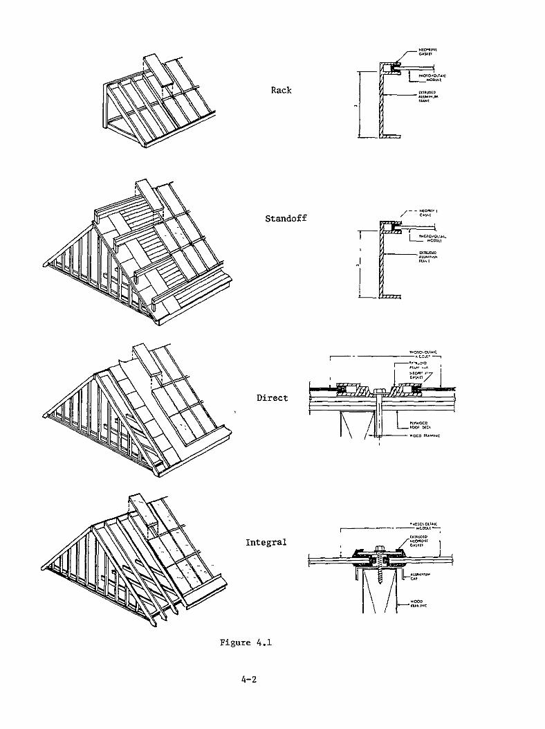
Four generic mounting types have been identified and defined in the
Residential Module and Array Requirement Study prepared by Burt Hill
Kosar Rittelmann Associates for the Jet Propulsion Laboratory Report
DOEJPL955149-791 Mounting types are
1 Rack Mounting
2 Standoff Mounting
3 Direct Mounting
4 Integral Mounting
Figure 41 shows the four mounting types and potential panelarray details
Several important characteristics of these mounting types must be
understood before operation and maintenance procedures can he described
The following is a brief description of each of these mounting types
1 Rack Mounting Rack mounted photovoltaic arrays can be located on
the ground away from the residence or on the roof of the residence
Of the four mounting types rack mounted panels are perhaps the
4-1
Rack
_-- EJEOftEI
CASStandoff
- L2A
Direct
Integral
Figure 41
4-2
easiest to install and maintain This is due to the relative ease
of accessibility to both the front and back surfaces of the panel
This is especially true of ground mounted arrays Panels can be
easily cleaned wiring systems are easily accessible and
generally mounting systems are easily reached for panel
replacement Also as this mounting type does not require array
waterproofing a minimum amount and number of materials are used in
this installation Therefore during maintenance procedures such
as panel replacement additional costs are not required for the
replacement of expensive materials other than the panel itself
ie no expensive gaskets or waterproofing materials are required
There are however some drawbacks to rack mounting of PV arrays
Structural costs both initial and maintenance can be high for
this type of mounting technique As seen in earlier studies the
use of wood is recommended for rack mounted arrays This implies
either specially treated woods or the painting of the rack
structure This requires additional maintenance tasks be performed
over te life of the array Another critical problem associated
with rack mounted arrays and related to the maintenance of such
arrays is the areas around the roof penetration caused by the rack
Special detailing and care must be given to these roof penetrations
to insure the watertight integrity of the roof
2 Standoff Mounting Elements that separate modules or panels from
the roof surface are known as standoffs By supporting the panel
away from the roof surface air and water can pass freely into the
module However the panel to roof surface distance is typically
small on the order of six inches and does not allow the easy
access of the rear surface of the panel This implies that all
installation and maintenance procedures need to be performed from
4-3
the easily accessed top surface This will require specially
designed mounting details and electrical integration details
However this mounting type does utilize fewer materials associated
with structural support of the array As with the rack mounted
arrays special attention must be given to the detailing of any
roof penetrations This implies that the overall installation
costs- for a standoff mounted array will be less than that
associated with a rack mounted array This does not imply that the
costs relative to operation and maintenance will be lower Unless
considerable effort is employed in the the thedesign of array
standoff mounted array will be extremely difficult and costly to
maintain
3 Direct Mounting Installation of direct mounted panels is
accomplished by attaching the panels directly to the roof surface
This mounting type eliminates the need for additional structural
supports Special care must be used in developing and detailing
direct mounting modules as they act as a waterproof membrane If a
typical panel is used perimeter waterproofing is needed if
shingles are used the simple overlapping technique will afford a
watertight surface
Due to the direct mounted systems inherent contact with the roof
several major problems exist These problems are similar to those
experienced when using a standoff mounted system It is necessary
for all installation and electrical detailing to ooccur on the
exposed surface thus allowing easy installation maintenance and
repair procedures
With shingle type modules special consideration must be given to
4-4
the maintenance procedure as the interruption of surrounding
modules must be minimized to reduce the probability of damaging
additional modules A more detailed discussion of this problem can
be found in Section 42 InstallationReplacement Type Description
4 Integral Mounting Integrally mounted panels are placed within the
roof structure itself The panels are supported by the existing
roof structural framing members and serve as the finished roof
surface Therefore the roof becomes a waterproof membrane With
the array acting as the roof special problems exist In the event
that a photovoltaic panel must be removed it is imperative that a
replacement be installed immediately Without a replacement the
roof is then open to the weather increasing the risk of damage to
the interior of the house
Installation and electrical connections as well as maintenance
procedures can be performed from the attic area of the residence
provided the panels are not attached above a cathedral ceiling
This mounting technique allows for venting of the back surface of
the panel However uneven heating of the array may occur in the
event that improper venting occurs in the attic space Therefore
care must be taken during the maintenance operation to insure that
the proper replacement of any installation material in the dead
space of the attic ceiling or cathedral ceiling takes place
Maintenance operations associated with the repair and replacement
of wiring the detection of electrical problems and the general
electrical testing of the array can take place during any weather
conditions as these operations can take place under the cover of
the residence It should also be noted that no additional roof
structure and associated maintenance of said structure will be
required in this mounting system
4-5
42 INSTALLATIONREPLACEMENT TYPE DESCRIPTION
In panelized construction there are three categories into which
installation and maintenance operations may fall These classifications
relate to the installationreplacement type and the procedures necessary to
perform these operations These three categories are
1 Sequential
2 Partial Interruption
3 Independent
Each of these categories imposes certain design installation and
maintenance requirements on the panel and array Both the installation
and operation and maintenance costs will be considerably different for the
three categories
The following is a brief description of each of the three panel
construction types
1 Sequential Sequential paneling requires the successive
installation andor removal of panels A good example of
sequential paneling installation is seen in the installation of
shingles The rows are installed successively in courses from vent
to ridge It is not unlikely in a sequential paneling installation
to find the first panel installed is the last panel removed In
the event that this first installed panel is damaged or requires
replacement all of the preceeding panels must be removed in order
to replace the damaged panel
Due to the sequential nature of this panel construction type costs
can be reduced as components of the system can be shared However
4-6
this construction type is the most expensive from a maintenance
standpoint In order to successfully utilize sequential paneling
for photovoltaic systems it is necessary to reduce the need for
maintenance requiring replacement of panels by insuring long
uninterrupted life of the panel This requirement may impose
severe restrictions on the materials and packaging of photovoltaic
arrays Therefore it is necessary to perform a thorough
optimization relating initial costs and maintenance costs over the
expected life of the system
Due to the potential for high maintenance costs associated with
sequential paneling systems it is not likely in the near future to
find photovoltaic arrays requiring strict sequential paneling
techniques in maintenance operations It is possible however to
have panels requiring sequential installation but not sequential
removal for maintenance purposes The shingle module is a perfect
example of this type panel
2 Partial Interruption A building panel which falls into a partial
interruption category can be replaced by disturbing only the
adjacent panels This technique will be more expensive to use for
the installation of panels but less expensive to maintain than the
sequential paneling technique It will be possible ifi this
technique for adjacent panels to use common parts However due to
the use of common parts it becomes necessary to disturb the
surrounding panels during certain maintenance procedures such as
panel replacement In the event that a panel must be removed-from
this type system it is necessary to replace it immediately with a
new panel or a dummy panel to insure the integrity of the mounting
system
4-7
3 Independent -Independent paneling is a panelized construction
where panels can be installed removed and replaced for maintenance
with no additional interruptions or disturbances of the surrounding
panels This panelized construction technique is -the least
expensive from a maintenance labor standpoint and from an
installation labor standpoint However materials cannot be shared
by adjacent panels thus increasing the materials costs associated
with this technique
Each of these installationreplacement types require different panel edge
detailing In order to generate cost data for maintenance procedures it
will be necessary to generate panel edge details associated with each
panelarray mounting type and installationreplacement type The following
section 43 PanelArray Details will explain individualized panel edge
details
43 PANELARRAY DETAILS
The finest level of detail associated with the design of a photovoltaic
array is that of the panel edge details These details will strongly
influence not only the installation costs but perhaps more critically
the maintenance costs associated with the replacement of a panel This
section will describe a number of details which were generated for this
study
Recalling from the previous section that there are three types of panelized
construction
Sequential
Partial interruption
Independent
4-8
specific details for each can be generated In some cases however these
edge details can be utilized in installations using any of the basic
mounting configurations
Figure 42 shows a detail utilizing sequential paneling techniques for both
installation and maintenance operations It can be seen that the
transverse section does not require gasketing material but the
longitudinal section employs gasket material in order to insure a watershy
tight membrane Therefore the overall installation costs associated with
this type edge detail can be reduced when compared to other details
described in this section During the maintenance operation however
other panels in the column and row must be disturbed Another important
feature of this detail is the possibility of incorporating the electrical
interconnects in the mechanical interconnect associated with the transverse
section This will likewise reduce the installation as well as the
maintenance costs
It is possible to have a panelized construction module that uses sequential
installation techniques but can be classified in the partial interruption
category for maintenance purposes The photovoltaic shingle module is an
example of such a device Figure 43 shows a portion of a photovoltaic
array using the shingle module The shingles are installed in rows moving
sequentially from eave to ridge The replacement of a shingle requires
only partial interruption for maintenance purposes As with the previous
detail gasketing material is not required for this detail to function as a
watertight membrane
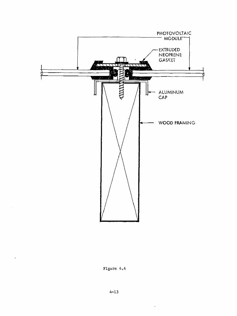
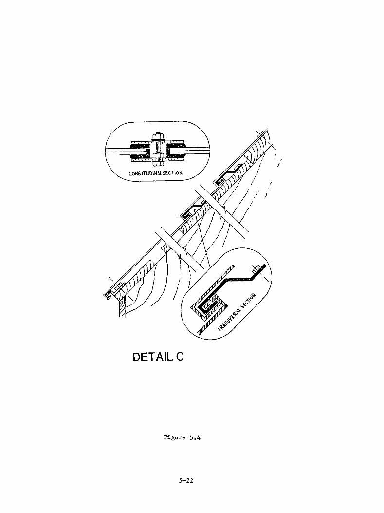
The details depicted in Figure 44 are examples of edge details used in an
integral or direct partial interruption installation This technique
requires the use of extensive gasketing material to insure watertight
integrity Also during a maintenance procedure which requires the removal
of a panel the four surrounding panels must be disturbed This increases
4-9
the probability of damage to other panels and their gasketing-material
This edge detail however is similar to those typically used in the
glazing industry and is a tried and proven method for the installation of
glass panels
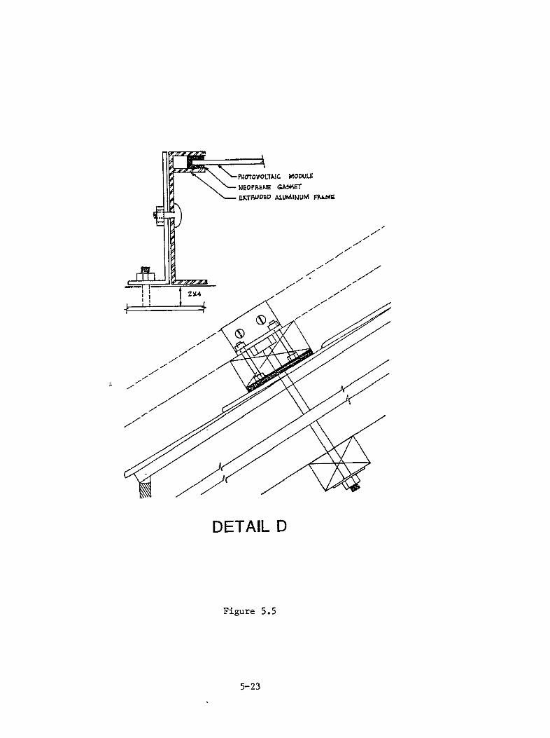
Figure 45 shows two details which can be used as vertical joints in an
integral or direct independent mounting system These details provide a
waterproof membrane without the use of gasketing material and provide for
quick and easy installation The horizontal joints are made by simply
overlapping the panels With the use of a special tool the removal of a
panel becomes a relatively simple operation
The simplest edge detail studied can be seen in Figure 46 This detail
can be used in rack and standoff applications and is an example of an
independent panelized construction type The panels surrounding a panel
requiring replacement will not be distrubed This detail is extremely
simple to install and the maintenance operations required can be performed
with little problem However this example is in need of additional
support structure in order to be utilized in an application This will of
course increase the overall installation cost but will have little effect
on the maintenance costs
Again it is important that these are example details only used for costing
purposes in the following sections Care must be used when attempting to
use these details for cost comparison purposes
4-10
Figure 42
4-11
-- Threaded terminal boss to receive plastic screw from
_ overlapping shingles
PRII TED CIRCUIT TA O Plastic Screw isOR ETL FOIL inserted and tighened to make high pressure
electrical connection etween negative
terminal here amp positive terminal of shingle underneath
Negative terminal registers+ereg I --with positive terminal _ underneath
Figure 43
4-12
PHOTOVOLTAIC MODULE
-EXTRUDED j NEOPRENE
ALUMINUM CAP
WOOD FRAMING
Figure 44
4-13
01PIAE~IWMTPh(FAL
PAMNL MUampT BE ASLE WII4TALK TOPOIONAL erTRF-pEF OF oWE CLIP
CLIP(FFl24
PAL MT BE 167LY
TENoIP F06 4MkJ CLIP TO FUICTIONPHOLY
6PECIAL CIMPER iIU4T 06 U60 TOE _ AELEA66 SACI- CLIP
Figure 45
4-14
PFROroVOL1AIC MODULE WOPRENE GAfKET ampYTUDEP ALUIIUM FhiLN1g
)7
Z-A
-A
Figure 46
4-15 5ORIGINAL PAG IOP POOR QUAITi
SECTION 5
OPERATIONMAINTENANCE
There are six basic topics pertaining to the operation and maintenance of
photovoltaic arrays which will be discussed in this section These general
topics include
1 General (normal) Maintenance
2 Cleaning
3 Panel Replacement
4 Gasket RepairReplacement
5 Wiring Repair
6 Termination Repair
Under each of these topics where possible a standard procedure was used
to identify operation and maintenance problems procedures and costs The
basic procedure used was first to identify problems associated with each of
the above mentioned topics The problem statement is followed by a
detailed description of maintenance procedures Having previously
identified mounting and panel construction details costs were identified
to perform the appropriate maintenance procedures In order to complete
the operation and maintenance cost study cost drivers were identified and
methods for reducing these costs have been recommended
It is important to note that the costs generated in this study are detail
and site specific and care must be used when attempting to determine the
applicability of these numbers relative to a manufacturers specific panel
detail As photovoltaic panels and arrays are not in abundant use it was
necessary to use where possible numbers relative to the installation of
components similar to the photovoltaic panels Estimates of the amount of
time necessary to perform certain installations and procedures were also
used
5-1
It is also important to note where detailed cost breakdowns are given a
contractor is not likely to quote a price for a maintenance procedure in as
much detail as is given in this study For example where travel set-up
and clean-up are itemized a contractor will provide a lump sum quote for
the entire maintenance task The cost operation will be the same on a
residence 10 miles from the contractors site as one 30 miles from the site
as quoted by the contractor
51 General (Normal) Maintenance
Normal maintenance is that maintenance which is required on a periodic
basis to reduce the chance of failure and maintain an accepted level of
performance Actions involved in normal maintenance include visual
mechanical and electrical inspection of panels fasteners and wiring
Also some photovoltaic arrays may require portions of the structure be
coated or painted in order to insure the integrity of the structural system
throughout the expected life of the array These normal maintenance
procedures could easily be performed by the owner of the photovoltaic
system or by a groundskeeper or by a general maintenance person The
required preventive actions depend on the panel design and the mounting
type relative to materials selected and exposure of those materials to
elements which could cause their degradation
Visual inspections and mechanical inspections require the inspector to
climb onto the roof for roof mounted array and across the array to gain
access to each panel For this reason visual and mechanical inspections
should be performed during the performance of another maintenance
operation Cleaning is one such operation which requires general access to
the outer surface of the panels If a defect does develop in a panel
visual inspection would be most revealing after the cleaning of the array
Having established accessibility to the array for visual inspections two
options are readily apparent
Option 1 Cleaning personnel could be specially trained to locate
5-2
potential problems
Option 2 The owner or qualified inspector could examine the panels
during the cleaning operation using ladders andor scaffolding
erected by the cleaning crew
Superficial visual inspections could be performed by the owner at any point
in time from any available vantage point
Normal electrical inspections should be performed on the system level The
method is therefore a systems problem and therefore beyond the scope of
this study
Problems which may be identified by visual and mechanical inspection
include minor gaps between panels loosened fastening devices paint on
frames or structures wearing or peeling broken cover glazing terminal
boot damage and terminal contact corrosionoxidation
Minor gaps between panels that form a watertight membrane may be sealed
by caulking with an elastomeric caulking compound if the gaps are not
visually noticeable and if the panels have settled into a stable position
Major gaps resulting from poor design poor installation or fastening
devices or from adverse weather conditions require more extension repair
procedures These procedures do not fall under the category of normal
maintenance and will be dealt with in sections 53 and 54
Loosened fastening devices could result from thermal cycling andor wind
induced uplift and vibration Procedures necessary for the repair of
loosened fastening devices could range from the simple tightening of these
devices (if no damage to the fastener or panel has resulted) replacement
of the fasteners (if threaded connections are stripped bent or corroded)
5-3
to total panel replacement (if the fasteners are not removable from the
panel)
There are two categories of painting associated with normal maintenance
procedures
1 Painting of the frames of the panels
2 Painting of the support structure
Painting of the panel frames may be required if those frames are of a
corrosive material or if the architectural character demands the color of
the frames be different than the natural color of the material from which
they are made Array rack structures may also require painting for the
same reasons The frequency of repainting will vary with the
weatherability of the coating used on the material and the climatic
conditions to which it is exposed Painting operations are carried out by
either the owner of the house or contracted to professional painters Due
to the location and the size of a residential photvoltaic array the later
the professional painter will most likely perform the painting operations
The procedures necessary for painting include cleaning the surface to be
painted scraping and sanding and applying paint to the clean smooth
surface Methods of applying paint to a surface include brushing
rolling and spraying
Painting costs will vary with the surface area to be painted the condition
of the surface the surface configuration and accessibility The costs
listed in Table 51 for the painting of frames were generated from figures
and formulas taken from Engelsmans 1979 Residential Cost Manual and an
5-4
overhead percentage developed from Means 1979 Building Construction Cost
Data File These costs were for the application of one coat of oil based
paint by brush In order to establish costs for frame painting a typical
array with the following specifications was used
Array Size - 1000 sq ft
Panel Sizes - 32 x 96 32 x 48 16 x 48
16 x 24 48 x 48
Frame Perimeter - 21-4
Frame Width - 2 internal I perimeter
Surface Area - 125 sq ft
Roof Height - I Story
Slope 450
The costs for painting a steel rack structure which supports the
photovoltaic array were based on surface area in square feet multiplied
by the cost per square foot for painting steel window sashes Surface area
was determined by examining the surface area per ton for light structural
steel listed in Means 1979 Building Construction Cost Data File multiplied
by the weight in tons of steel for the rack structure previously
determined in Table 14-19 of the Residential Photovoltaic Module and
Array Requirement Study The costs per square foot were obtained from
Engelsmans 1979 Residential Cost Manual
The costs for painting a wood rack structure were also based on surface
area in square feet multiplied by the cost per square foot for painting the
trim The surface area was determined from the number of board feet listed
in Table 14-20 of the Residential Photovoltaic Module and Array
Requirement Study A breakdown of these costs can be seen in Table 51
Broken cover glazing terminal boot damage and contact corrosionoxidation
will be identified by normal maintenance procedures but their repair is
5-5
45-4 45-4 45-4 45 t-4 44I-0
x0 x x x ARRAY SIZE 24 -O 24-0 24-0 24-0 24-0
32 32 16 16 48 PANEL SIZE x x x x x
96 48 48 24 48
1 FRAME EQUIVALENT AREA (Lna )1535 1875 2895 3575 1490(Lineal Ftt x 25) ____
2 PAINTING COSTSQ FT 023 023 023 023 023(Labor and Materials)
3 COST OF FRAME PAINTING (Labor and Materials) $35305 $43125 $66585 $82225 $34270
TRAVELTRANSPORTATION COST $ 7536 $ 7536 $12560 $15072 $ 7536 ($2512day) (3 days) (3 days) (5 daysi (6 days (3 days)
4 (ROOF) SET UPCLEAN UP $ 2886 $ 2886 $ 4810 $ 5772 $ 2886 ($962day) (3 days) (3 days) (5 days (6 days) (3 days)
TOTAL FRAME PAINTING COST (ROOF) $45727 $53547 $83955 $10306S $44622
5 (GROUND) SET UPCLEAN UP $ 1314 $ 1314 $ 2190 $ 2628 $ 1314 ($438day) (3 days) (3 days) (5 days (6 days) (3 days)
TOTAL FRAME PAINTING COST $51975 $81335 $99925 $43050(GROUND) $44155
1 FRAME EQUIVALENT AREA = (Lineal Ft of frame) x [(25) Multiplier used to compensate for the degree of difficulty in paintshying window frames]
2 PAINTING COSTSQ FT = Labor and material costs for sanding primer and one coat finish + 20 additional labor cost for sloped application
3 COST OF FRAME PAINTING = (FRAME EQUIVALENT AREA) x (PAINTING COSTSQ FT)
4 TOTAL FRAME PAINTING COST (ROOF) = (COST OF FRAME PAINTING) + (TRAVEL TRANSPORTATION COST) + [(ROOF) SET UPCLEAN UP COST]
5 TOTAL FRAME PAINTING COST (GROUND) = (COST OF FRA1E PAINTING) + (TRAVEL TRANSPORTATION COST) + [(GROUND)
SET UPCLEAN UP COST]
Table 51 Frame Painting Costs
5-6
32x96 (Panels) RACK STRUCTURE PAINTING COSTS
(costs for 1 field coat brush light framing)
Rack Structure Wood Steel
Rack Equivalent Area 2114 SF 1690 SF (RfMS)
Painting CostsSqFt $015 $015SF
Cost of Frame Painting $317 $25350SF Operation
Travel Time (Cost) $2512 $7536 $5024 (3 Days) (2 Days)
Ground Set UpClean Up $1314 $ 876 $438day
TOTAL RACK PAINTING COST $4055 $31250
Table 52 Rack Structure Painting Costs
TOTAL PAINTING COSTS (32x96 Panels) (8x133) Array
Rack Structure Wood Steel
Rack Painting Cost $40550 $31250
Metal Frame Painting Cost (32 x 96) $44155 $44155
TOTAL PAINTING COST $84705 $75405 (Rack + Frame)
Table 53 Total Rack and Frame Painting Costs
5-7
HOURLY LABOR RATE (Pop
SOURCE COMMENTSQJANITY LABOR TYPE COSTHR
Painter $ 8 00 Fnpelmins 1979 Reidential (et MatUi Profits are not irnluded Overhead 31 $ 250 liens 1979 Building Constnlction Cost Diti Norna] profits ire 102 of the
total cost
TOTAL $1050
TRANSPORTATION amp TRAVEL COST TIME REQUIRED AVECOST OPERATION COMMENTS
30-45 Min $ 6 56 Travel to site Hourly Labor Cost x hours required $ 6 00 Transportation to site $0 30mile x 20 miles $12 56 TravelTrausportation to Site
30-45 in $ 656 Travel from site Hourly Labor Cost x hours required
6 00 Transportation from site $0 30mile 20 miles
$12 56 TravelTransportation from site
$12 56 TravelTransportation to site $12 56 TravelTransportation from site $2512 TOTAL TRAVEITRAI1SPORTATION
SET UPCLEAN UP (Painting)
LOCATION TIME REQUIRED AVE COST OPERATION COMMENTS
ROOF 25-30 in $ 4 81 Set Up Ladders amp Equipment Estimate 25-30 in 481 Clean Up Ladders amp Fquipment
$ 9 62 TOTAL ROOFSET UPCLEAN UP
GROUND 10-15 Min $ 2 19 Set Up Tools amp Eqtipsent Estimate 10-15 in 2 19 Clean Up Tools amp Equipment
$ 438 TOTAL GROUND SET UPCLFAN UP
Table 54 Painting Cost Base
5-8
not a normal maintenance procedure Rectification of these problems are
corective in nature and will be discussed later in this section
52 Cleaning
The deposition of airborne dirt particles on photovoltaic panels has
historically been one of the most significant factors relative to power
output degradation in experimental photovoltaic power systems Although
the presence of particulants is universal the rate of accumulation and
type of particulant buildup will vary with each location and with the
ability of the cover glazing material to retain dirt Categorically
urban suburban and rural locations show great differences in the rate of
accumulation and type of airborne particle
Possible cover glazing materials can be divided into several categories
inorganic glass sheet acrylic sheet fiberglas reinforced sheet polyester
film materials and laminated polycarbonate films Acrylic sheet displays
the greatest dirt accumulation and inorganic glass sheet and laminated
polycarbonate films retain the least amount of dirt particles
Cleanability the ease of removing dirt particles from the surface relies
on the bond between the cover glazing and the dirt particles The bond
strength is related to the porousity surface texture and chemical
stability of the cover glazing as well as the chemical stability of the
dirt particles Non-porous smooth textured chemically stable materials
tend to be easily cleaned with a variety of cleaning solutions while
porous rough textured chemically unstable materials require more effort
with special cleaning solutions mild enough to leave the chemical makeup
of the material unchanged As a result of the crystalline bond within
inorganic glass sheets glass is easy to clean The weak bonds in acrylic
sheets are easily broken by a variety of chemical solutions and are
5-9
therefore easy to scratch and difficult to clean
Transparent materials currently used in residential applications with the
exception of replaceable storm windows and skylights have been limited to
inorganic glass sheets Operations for cleaning glass in the home are
normally performed by the owner of the residence Motives for cleaning
include the need for an unobstructed visual release to the exterior of the
home and the need to remove dirt which is easily noticed
The cleaning sequence involves spraying an ammoniawater solution on the
window wiping the solution and dirt from the surface with a paper towel
and polishing the surface with a clean paper towel In large residences
the window cleaning operation is contracted to window cleaning
professionals The cleaning sequence used by professional window cleaners
begins with the sponging down of the glazing with an ammoniawater solution
or a solution of trisodium phosphate in water squegeeing the surface dry
and wiping the perimeter of the glazing with a cloth
Section 3 clearly points out the reluctance of homeowners to perform any
maintenance procedures within the home Cleaning is no exception
especially in remote locations such as the roof or the exterior windows
located outside of convenient reach This is exemplified by the lack of
cleaning maintenance performed on the cover glazing of existing thermal
collectors It can therefore be assumed that photovoltaic panels will
also suffer from this reluctance to perform even the most routine
maintenance procedures
Currently photovoltaic panels are glazed with one of three materials
inorganic glass sheet thin films and RTV silicon encapsulant Although
the purpose of these materials is the same maintenance required to clean
5-10
them demonstrates the extremes in method and cleanability Any of the
methods previously discussed in this section can be used to clean inorganic
glass sheet but RTV silicon must be scrubbed twice with a solution of hot
water and pumice Experimental films and coatings over encapsulants
similar to RTV silicon may increase the cleanability of the cover glazing
only if the resulting surface is smooth and flat Ripples andor
depressions in the surface will allow pockets of dirt to accumulate as
these areas cannot be squeegeed
Cleaning cost variables include but are not limited to the time for
performing the tasks required to clean the cover glazing materials the
number and size of panels and the gasketingframe details used (Panels
having no perimeter frame or gasketing to obstruct cleaning operations
could eliminate the need for wiping edges thus reducing the number of
tasks required time required and overall cost of the operation) Total
cleaning costs however also include costs inherent to all maintenance
activity such as material costs for transportation equipment costs
general overhead and labor costs for travel time and set upclean up time
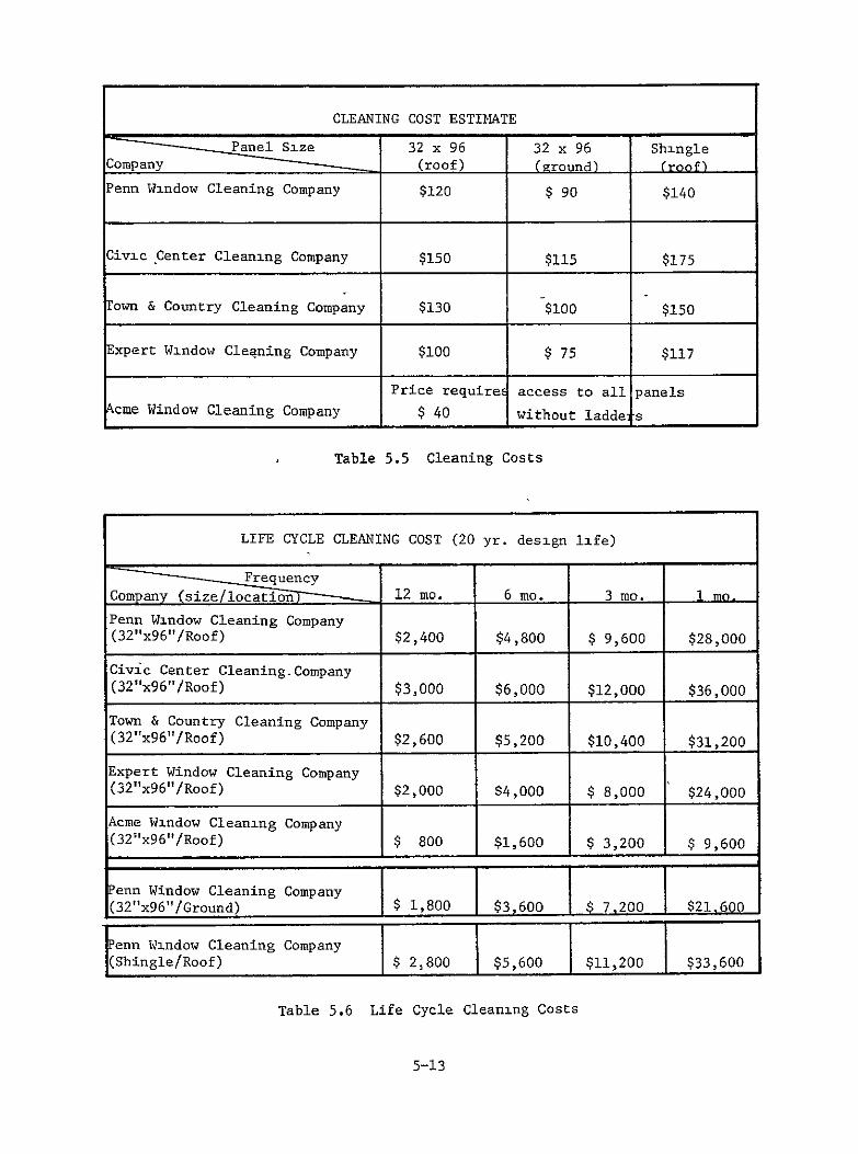
The costs given in Table 5 5 are estimates given by professional window
cleaners based on a typical array with the following specifications
Array Size 1000 sq ft
Panel Size 52 - 32x96
Shingle Size 5 x 36
Mounting Type Direct Mount Roof Rack Mount Ground
FrameGasket Type Picture Frame
Roof Height 1 Story
Slope 456 from the horizontal
The labor figures involved were based on the following cleaning process
5-11
Sponge clean glazing with an ammoniawater solution or a solution
of trisodium phosphate in water
Squeegee the surface dry
Wipe the excess solution from the pirimeter with a soft cloth
In order to demonstrate the dramatic effect cleaning frequency
has on cost Table 56 presents life cycle costing data for the
cleaning based on the estimates given in Table 55 and over a
twenty-year design life The basic conclusion as a result can
only be cleaning should not be a general maintenance procedure
A preferred method would be to instruct the owner to hose down
the array on a periodic basis
Cost driversmethods for cost reduction
Materials used for cover glazing
Improve cleanability
Reduce frequency of cleaning due to dirt retention
Accessibility of Array
Mount array on ground
Provide ladder support over the face of the array that can be
easily moved across the array while loaded similar to the
rolling ladders in bookstores and libraries See Figure 51
Provide foothold or ledge between horizontal rows of panels
5-12
CLEANING COST ESTIMATE
Panel Size 32 x 96 32 x 96 Shingle Company (roof) (ground) (roof) Penn Window Cleaning Company $120 $ 90 $140
Civic Center Cleaning Company $150 $115 $175
rown amp Country Cleaning Company $100$130 $150
Expert Window Cleaning Company $100 $ 75 $117
Price require access to all panels
cme Window Cleaning Company $ 40 without laddels
Table 55 Cleaning Costs
LIFE CYCLE CLEANING COST (20 yr design life)
_Frequency Company (sizelocation 12 mo 6 mo 3 mo I me
Penn Window Cleaning Company (32x96Roof) $2400 $4800 $ 9600 $28000
Civic Center CleaningCompany (32x96Roof) $3000 $6000 $12000 $36000
Town amp Country Cleaning Company (32x96Roof) $2600 $5200 $10400 $31200
Expert Window Cleaning Company (32x96Roof) $2000 84000 $ 8000 $24000
Acme Window Cleaning Company (32x96Roof) $ 800 $1600 $ 3200 $ 9600
Penn Window Cleaning Company T I (32x96Ground) $ 1800 $3600 $ 7200j $21600
jPenn Window Cleaning Company I (ShingleRoof) $ 2800 $5600 $11200 $33600
Table 56 Life Cycle Cleaning Costs
5-13
Pigure 51 CleAning Operation Using a Rolling Ladder
-5-14
Travel
Cleaning schedules for photovoltaic arrays do not require
specific times for the cleaning operation to occur and could
therefore tolerate a time variable A route could be
established to reduce transportation and travel costs
Frequency
Frequency of professional cleaning operations may be reduced
by rinsing the array with water from a simple garden hose or a
pole device similar to that used in swimming pool cleaning
operations altered to accept a garden hose
53 Panel Replacement
Potential problems leading to the replacement of photovoltaic panels are
those problems integral to the panel that cannot be rectified on site
without further damage to the panel andor the elements within that panel
These problems could include
Cracked worn or otherwise damaged glazing
Damaged terminals
Cracked sills
Broken interconnects
General delamination of the composite panel
5-15
The origin of these problems is generally not a function of the operation
and maintenance of the panels but can be traced to the design and
construction of the panel and its installation
The procedures necessary for the replacement of a panel can be listed under
the following general categories
Electrical disconnect
Removal of fastening devices
Removal of gasketing materials (watertight membrane system only)
Removal of panel
Installation of replacement panel
Installation of gasketing material
Installation of fastening devices
Electrical connection
Few panels require all of the above-mentioned procedures for their
replacement and specific details may alter the above sequence For
example rack mounted arrays do not require gaskets to provide a watertight
membrane Panels which are required to form watertight membrane systems
may be designed and supplied with gaskets attached to the panel or in the
case of a shingleoverlap panel the system provides watertight integrity
without gaskets The electrical disconnection of the panel may follow the
panel removal procedure in which case the electrical connections would
5-16
precede panel installation
Within the general classifications previously mentioned each panel
design has a specific set of procedures arranged in a sequence unique to
that array Further evaluation of these procedures must therefore be
detail specific Using the panelarray details described in section 43
replacement procedures and the associated costs can be developed for these
specific details
In order to establish the cost of panel replacement it was necessary to
standardize panel weight shape and size The weight limitations were set
according to an individuals lifting capacity of 50 to 60 lbs Actual
panel weights based on material weight are listed in Table 57 With the
exception of the shingle panel all panels studied were standardized to a
rectangular shape 32 x 96 The shingle panel is a hexagonal shape with
an area of approximately 1 sqft
Other variables affecting cost which have not been standardized include
mounting location mounting type and mounting method All of the details
shown in Section 43 could be ground mounted however only detail D
(Figure 46) has been costed for both roof and ground mounting
Electrical disconnection and connection varies with the type of connector
used Currently available are two types of quick connectors Sure Seal
Connectors by ITT Cannon and Scotchlok Self Stripping Connectors by 3M
However a standard J-Box connection is used by most of the photovoltaic
manufacturers to date
Cost breakdowns for panel replacement are listed in Tables 58 to 512
The development of these costs required the use of installation costs
associated with similar components found in similar mounting
5-17
PANEL TYPE
SQ
FT
32 x 96
32
48
16 Xx
48
16
24
48 X 48
Tedlar 0 0 0 0 0 0
_ _ _ _ _
Cells amp Pottant 0 0 0 0 0 0
GRC 11 235 118 59 30 176
Frame 62 38 31 19 45 Glass Reinforced
Concrete
TOTAL WEIGHT Pounds) 2412 1218 621 319 1805
Tedlar Cells amp
otatPottant
0
0
0
00
0
0
0
0
0
0
0
0
10=u n116 Aluu 6 185 92 46 23 14
Frame - 62 38 31 19 45
TOTAL WEIGHT (Pounds)
332 Annealed Glass Cells amp Pottant
-
125
0
247
267
0
130
134
0
77
67
0
42
33
0
185
20
0 OWN 116 Alun 086 185 92 46 23 140
Frame
TOTAL WEIGHT (Pounds)
18 Tempered Glass Cells amp Pottant
167
0
62
514
356
0
38
264
178
0
31
144
89
0
19
75
45
0
45
525
267
0
116 Auu 086 185 92 46 23 140
Frame - 62 38 31 19 45
-
TOTAL WEIGHT (Pounds)
18 Tempered Glass Cells amp Pottant 118
-
167
0
60
356
0
i0
178
0
16-6
89
0
J 45
45 267
0 0
aered 167 3 178 8 9 451 267
Frame TOTAL WEIGHT
(Pounds)
62
774
38
394
31
209
19
108
45
579
Table 57 Panel Weights
5-18
DETAIL TIME REQUIRED AVECOST
LABOR COST OPERATION COMMENTS
A
H
180-260 min
84 sec (14 ml
135-195 min
84 sec (1-4 min
$ 8504 $ 026 $ 8530
$ 6678
$ 026 $ 6704
Mechanical Replacement of Panel Electrical Connection amp Disconnection
(Modular Quick Connect)
Mechanical Replacement of Panel
Electrical Connection amp Disconnection (Modular Quick Connect)
42 sec + 42 sec - 84 sec (1100hr) Labor Rate See Table 5 23 for electrical
connection and disconnection cost breakdowns
C-I $ 8368 lech-Elect Replacement of Ist Panel
C-2 $ 9696 ecb-Elect Replacement of 2nd Panel
c-3 $11024 ech-Elect Replacement of 3rd Panel
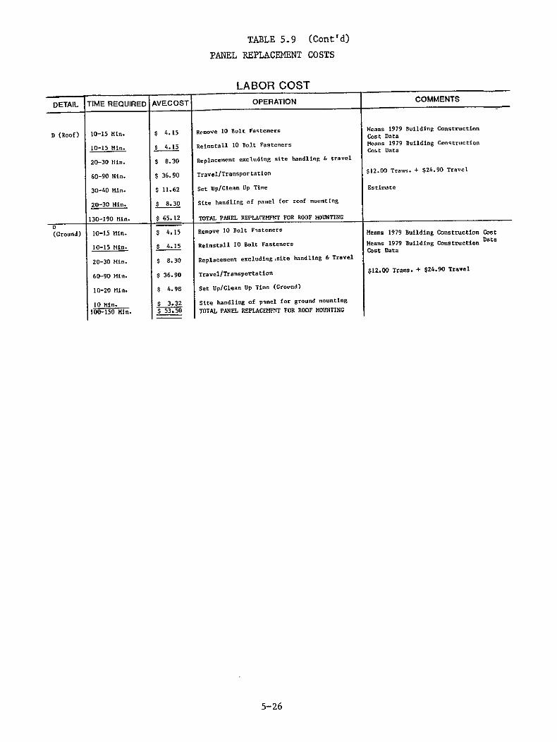
D Roof 130-190 min
84 sec (14 min $ 6512
$ 026 $ 6542
Total panel replacement for roof mounting
Electrical Connection amp Diaconnection ech-hlect Replacement
D Ground 100-150 min
60 sec (14 in
$ 5350 $ 018 $ 5368
Total Mech Replacement for ground mounting
Hech-Elect Replacemet for ground mounting
Less 40 for ground mounted locations
Shingle 180-250 min
326 see (54 min )
$ 5143
$ I on(
$ 52 43
Total shingle Mach replacement for roof
mounting Electrical Connection amp Disconnection Hecth-Flect Replacement for roof
163 sec x 2 terminals - 326 sec
Table 58 Panel Replacement Costs
5-19
PHOTOVOLTAIC MODULE ---
EXTRUDED
J ALUMINUMv
WOOD FRAMING
shy
DETAIL A
Figure 52
Picture Frame C Gasket Detail
5-20
PAiL MU6T Sf ASL
WIWTJP TOtLONAL e6Fl9beF OF OJE CLIP
DETAIL B
Figure 53 ORIGINAT PAQI
OFM POORQ
5-21
LONGITUDM SECTIO)4 I
1
DETAIL C
Figure 54
5-22
7OTOVOLIL1C MODULE
VXPLJPWV ALUMtlJINM FAMK
-A
-A shy
5-23
DETAIL D
Figure 55
5-23
- Threoded tennInol boss toi _ _ receive plsfic screw frm
- 47 overlapping shingles
PRINTED CIRCUIT- p scmr
OR METAL FOIL I inserted ond tioenea j- ~N-- - - -to make h presstwe
eleciricol corinectior - betweer negctive
Posltive terinal o shingle underneotl
Neggtive terminal registers +C 0+ -with Positive termnJ
SHINGLE
Figure 56
5-24
TABLE 59
PANEL REPLACEMENT COSTS
LABOR COST DETAIL TIME REQUIRED AVECOST OPERATION COMMENTS
A 25-30 Min $ 913 Remove 22 14 x2 lag screws oure eManResidential Cost manual
25-30 Kin $ 913 Reinstall I4x2 lag screws ource ganaResidential Cost MInual
10-20 Min $ 498 Remove alum cross members Estimate
10-20 Hi $ 498 Reinstall alum cross members Estimate
70-100 Min $ 2822 Replacement excluding site handling amp travel
60-90 in $ 3690 TravelTransportation $1200 Trans $2490 Travel
30-40 Hin $ 1162 Set UpClean Up Time Estimate
20-30 in $ 830 Site handling of panel for roof mouting Estimate
180-260 MIn $ 8504 TOTAL PANEL REPLACEMENT FOR ROOF MOUNTING
H 15-20 in $ 581 Release 10 snap clips amp panel Estimate
10-15 Min $ 415 Snap new panel into place Estimate
25-35 Kin $ 996 Replacement excluding site handling and travel
60-90 Min $ 3690 TravUTruasporLtaion $1200 Trans + $2490 Travtl
30-40 Min $ 1162 Set UpClean Up Time
20-30 Min $ 830 Site handling of panel for roof mounting 135-195 Iin 6678 10lAL PANEL REPLACEMENT FOR RDOOMOUNTING
5-30 MI 4 9 13 Rtmov- Flstaner (It amp clip) FatInite
Mt-25ln 747 ReInstill Ftcners (nails amp cltps) FLsMIt
15-21 Min $ 581 Remove Ridge Vent at Fl hin source einslResidential Cost Manual
10-15 Kin $ 415 ReinstilI Ridg Vent or Pulshing Source MensResidential Cost Manual
70-90 Mtin q 2456 Replacement exeldtnp site handling amp trivel
60-90 lfle $ 36 90 TravelTransportition $12 00 Trans + $2490 Travel
30-40 in $ II 67 Set UpClein lip Time gee Table 514
(I Panel)C-I
20-30 in 180-250 Hin
$ 830 $ 8338
site handling of panel for roof monting TOTAL PANEL REPLACEIENT FOR ROOFtOUNTThG
See Table 5 15 Replacement of top panel
20-25 Kin 747 Remove Fasteners (nails amp clips) pstisnte
15-20 Hin $ 5 81 Reinstall Fasteners (nails amp clips) Estimate
35-45 Min $ 1328 RemoveReinstall Each Additional Panel
180-250 Min s 8338 Total panel replacement for lst panel See C-I above
(2 PanLI) C-2
35-45 215-295
i1n tIm
$ 1328 $ 9666
RenoveReinstll I Additional Panel TOTAL PANEL REPLACEMENT FOR SECONDPANEL C-2 = Replacement of second panel
180-250 Kin $ 8338 Total Panel Replacenent for First Panel See C-I above
(3 Panel) C-3
70-90 Min 250-340 ini
$ 2656 $109 94
RenoeReinstali Two Additional Panels
TOTAL PANEL REPLACEMFNT FOR THIRD PANEL
2 - $1328
C-3 = Replacement of third panel
5-25
TABLE 59 (Contd)
PANEL REPLACEMENT COSTS
LABOR COST
DETAIL TIME REQUIRED AVECOST OPERATION COMMENTS
D (Roof) 10-15 Min $ 415 Remove 10 Bolt Fasteners Means 1979Cos t Daa Building Construction
10-15 Min $ 415 Reinstall 10 Bolt Fasteners Means 1979 Cost Data
Building Contruction
20-30 Min $ 830 Replacement excluding site handling amp travel
60-90 Hin $ 3690 TravelTransportatLon $1200 Trans + $2490 Travel
30-40 Kin $ 1162 Set UpClean Up Time Estimate
20-30 Hin $ 830 Site handling of panel for roof mounting
130-190 Min $ 6512 TOTAL PANEL REPLAC(7HFNT FOR ROOF MOUTING
(Ground) 10-15 Min
10-15 Min
$ 415
$ 415
Remove 10 Bolt Fisteners
Reinstall 10 Bolt Fasteners
Means 1979 Building Construction Cost
Means 1979 Building Construction Data
Cost Data
20-30 Kin $ 830 Replacement excluding site handling amp Travel
60-90 Min $ 3690 TravelTransportation $1200 Trans + $2490 Travel
10-20 Min $ 498 Set UpClean Up Time (Crotnd)
10 Min $ 332 Site handling of ploel for ground mounting
100-150 Min $ 5350 TOTAL PANEL REPLACMENT FOR ROOF MOUNTING
5-26
TABLE 510
PANEL REPLACEMENT COST BASE
HOURLY LABOR RATE
QJANTITY LA3OR TYPE WOSTHR SOURCE COMMENTS
I C] aerRoofer $ 8 00 I ngn 1979 Pesidntl-il Coast -niI Due to th dmplicrtv of tit
lonne tion devices qvilble It I LaborLr (Bidr) $ 6 50 wa d eroned tit pinel replicement 2 Crew Cot $14 50 would not require an electrician
Overhead 37 4 5 42 Hans 1979 Io dinp Construction Cast Pit
2 TOTAL CRrw co] 319 92
TRANSPORTATION TRANSPORTATION amp TRAVEL COST
TIME REQUIRED AVE COST OPERATION COMMENTS
30-45 Mio $12 45 Travel to site Hourly 6 00 Transportation to site $0 30mile x 20 miles
$18 45 TravelTransportateon to sire
30-45 Min $12 45 Travel from site Hourly 6 00 Transportation from site $0 30sle x 20 miles
$1845 TravelTransportation from site
30-45 Hin $1845 TravelTransportation to site 30-45 Min $18 45 TravelTransportation from site 60-90 ILa $3690 TOTAL TRAVELTRANSPORTATIONDAY
SET UPCLEAN UP
LOCATION TIME REQUIRED AVECOST OPERATION COMMENTS
Roof 15-20 lin $ 5 81 Set Ip Ladders A Equipment Estimate
15-20 min $ 581 Clean Up Ladders ampFquipment 30-40 min $1162 TOTAL ROOF SFT UPCLEAN UP TIME
Ground 5-10 min $ 249 Set Up Tools amp Equipment 5-10 sin $ 249 Clean Up Tools amp Fquipment Estimate
10-20 min $ 498 TOTAL GROUND SET UPLEAI UP1TIME
HANDLING
LOCATION TIME REQUIRED AVE COST OPERATION COMMENTS
Roof 10-15 mn $ 415 Remove ModulePanel from Roof Estimate of handling glazing from 10-15 sin $ 415 Raise NodulePanel to Roof roof to truck
20-30 sin $ 830 TOTAL HANDLING OF MODULEPANEL ON SITE
Ground 5 sLn $ 166 Carry ModulePanel to Truck Estimate of handling glazing from 5 mln $ 166 Carry ModuleFasel to Rack ground mounted rack to truck
10 sin $ 332 TOTAL HANDLING OF MODULEPANEL ON SITE
5-27
TABLE 511
SHINGLE REPLACEMENT COSTS
LABOR (OS I DETAIL TIME REQUIRED AVECOST OPERATION COMMENTS
Shingle 20-40 n $ 5sn Pve 4 Shlnrles
20 Min S 3 67 Reinstill 4 hlsinple
40-60 Ilin $ 917 R 1ptneI Shilnge xctdlirg Ilndi In amp Travel
60-90 Bin $ 257b TrVvelTransportltlon
50-60 Min $ 10 a set UpClean lip
30-40 Kin $ 642 site Handling of Shingle for Roof Mounting
180-250 Hi $ 5143 IOTA SHINGLE RFPILLINT FOR ROOF NOINIING
___5-28
TABLE 512
SHINGLE EPLACEN T COST BASE
HOURLY LABOR RATE I (O n cr-)
QJANTITY LABOR TYPE COSTHR SOURCE COMMENTS
I GlazierRoofer $ 8 00 - rngieans 1979 Reldential Cost 1nu
Overhead 374 $ 3 00 - Means 1979 Building Constrarfion Cot Dat
I TOTAL CREW COST $iI 00
TRANSPORTATION amp TRAVEL COST TIME REQUIRED AVE COST OPERATION COMMENTS
30-45 Min $ 6 88 Travel to site $ 6 00 Transportation to site
30-45 Min $1288 TravelTransportation to site
30-45 Min $ 6 88 Travel from site $ 6 00 Iransportation from site
30-45 in $1288 TravelTransportation from ite
30-45 Min $1288 TravelTransportation to site 30-45 Kin $1288 TravelTransportation from site
60-90 Min $2576 TOTAL TRAVELTRANSPORTATION
SE I UPGLEAN UP locreuw)(Oe
LOCATION TIME REQUIRED AVE COST OPERATION COMMENTS
Roof 25-30 min $ 504 Set Up Ladders amp Equipment ESTIMATE 25-30 mln $ 504 Clean Up lidders amp Fquipment 50-60 min $1008 TOTAL ROOFSET UPCLE UP TIME
Ground 10-15 aln $ 230 Set Up Tools amp Equipment ktitfA1a
10-15 rain $ 230 Clean Up Tools 6 Equipment 20-30 sin $ 460 SETTOTAL CROUND UPCl EAMUP TIMF
HANDLING LOCATION TIME REQUIRED AVE COST OPERATION COMMENTS
Roof 15-20 rin $ 321 Remove ModulePanel from Roof Estimate of handling a 32x96 sheet
15-20 sin $ 321 Raise ModulePanel to Roof of glass from roof to truck 30-40 sin 8 642 TOTAL HANDLING OF MODULEPANEL ONSIT
Ground 5 in $ 092 Carry ModulePanel to Truck Estimate of handling a 32x96 sheet 5 min $ 092 Carry ModulePanel to Rack of glass from ground mounted rack to 10 min $ 184 TOTAL HANDLING OF NODIIEPANEL ONSITF truck
5-29
configurations An example would be a standard sloped glazing system
which compares to a integrally mounted photovoltaic panel The time
required to perform the necessary tasks was determined and the average cost
is then a product of the mean time required and the total hourly crew
cost of the labor type performing the task
Hourly crew costs were obtained from Engeslmans 1979 Residential Cost
Manual Overhead figures were obtained from Means 1979 Building
Construction Manual and added to the hourly crew costs to produce the
total labor costs In all cases the average cost of an operation is the
produce of the mean time required to perform that operation and the total
hourly crew cost
Travel time and costs for transportation remain constant regardless of
panel variables The time required to travel to and from the site was
estimated for a distance of 20 miles A mileage rate of $030 per mile was
used The total travel cost also includes hourly crew costs Setup
cleanup costs and handling costs vary with the mounting type location and
crew size
Cost driversmethods of cost reduction
Weight
Reducing the weight of the panel will increase the ease of
handling
Size and Shape
Optimize the size and shape of the panel remembering this
application is for residential job sites and special requirements
exist
5-30
Fastening Devices
Fastening devices should be designed to be removed quickly and
easily thus reducing the time and cost of replacement
GasketingFraming
Attach the gasketing to the frame or to the panel in order to
reduce the number of pieces removed and reinstalled during the
replacement operation
Design gasketing and framing in modular units requiring as little
disturbance of other panels as possible during the replacement
of a panel
Accessibility of Array
Mounting of the array on the ground allows easy accessibility
for maintenance purposes
For roof locations provide a ladder supported over the face of the
array that can be easily moved across the array while loaded
similar to the rolling ladders in bookstores and libraries
Provide footholds or a ledge between horizontal rows of panels
Frequency of replacement
Design parts of the panel which must remain integral to the panel
such that they will perform their functions for the design life
of the panel
5-31
Design those parts of the panel which may degrade rapidly such
that they may be removed without the removal of the entire panel
Mounting Technique
Mount panels as independently as possible to reduce the disturbance
of surrounding panels in a replacement operation
Avoid sequential mounted panels Their requirement to disrupt or
remove other panels during a replacement procedure increases the
risk of damaging surrounding panels
54 Gasket Replacement
Gasketing for the purpose of this study will be limited in definition to
any ring or continuous strip of resilient material joining the panels of an
array in such a way that a watertight seal between panels is created
Problems which require the replacement of gasketing include physical
deterioration of the material due to airborne pollutants andor due to
thermal cycling mechanical separation of the gasket resulting from
inadequately designed or installed fastening devices and localized damage
caused by vandals or vermin
The need for gasketing will vary with mounting type panelized construction
type and with the specific detail used Rack and standoff mounted arrays
require no panel to panel gasketing as a watertight membrane is not
required Shingleoverlap panels provide a watertight membrane but require
no gasketing However direct and integral mountings require the use of
panel to panel gasketing to form waterproof seal
The procedures for the replacement of damaged gasketing will also vary with
5-32
the type of gasket detail used Two generic gasket types have been
identified Tape strip and picture frame C gaskets Detail A in Figure
57 is an example of a picture frame C gasket The procedures necessary
for replacing such a gasket involve all the operations necessary for panel
replacement and the additional operation required for the removing of the
gasket from the frame and installifng a replacement A slight modification
of this detail is seen in Figure 58 Detail A and is an example of a
structural H gasket The replacement of such a gasket requires the same
procedures as mentioned above
Detail B as shown in Figure 59 is an example of a tape strip gasket
The strip gasket occurs in the transverse section of the panel The
procedure for replacing the gasket includes removing the bolts fastening
the cross members removing damaged gasket (top only) installing new
gasket in its place and reinstalling the cross members
The labor costs for gasket replacement were developed using the same
methods as developed for labor costs for panel replacement A summary of
these costs and time required to complete the operations is given in Table
513
Cost DriversMethods of Cost Reduction
Degradation of materials
Exposed gasketing material should be designed to withstand all
expected environmental conditions over the life of the system
Array Accessibility
The mounting of the array on the ground allows for easy
accessibility for maintenance purposes
5-33
DETAIL Aa Figure 57
DETAIL Ab Figure 58
DETAIL Bc
Figure 59 Gasket Details
5-34
LABOR COST DETAIL TIME REQUIRED AVECOST OPERATION COMMENTS
A 25-30 Min
25-30 Min
10-20 Min
10-20 Min
70-100 Min
60-90 Min
30-40 Kin
20-30 Min
180-260 Min
$ 913
$ 913
$ 498
$ 498
$2822
$36 90
$11 62
$ 8 30
$8504
Remove 22 14x2 lag screws
Reinstall 14x2 lag screws
Remove alum cross members
Reinstall alum cross members
Replacement excluding site handling amp travel
TravelTransportation
Set UpClean Up Time
Site handling of panel for roof mounting
Total panel replacement for roof mounting
Source Means 1979 Building Cost Data
Source Means 1979 Building Cost Data
Estimate
Estimate
$12 00 Trans $24 90 Travel
Estimate
Estimate
5-10 Kin
5-10 Min
190-280 Min
$ 2 49
$ 2 49
$90 02
Remove damagedweathered gasket
Install new gasket
TOTAL CASKET REPLACEMENT
Estimate
Estimate
B 0 $ 0 00 No gasket involved
C 15-25 Min
10-20 Min
5-10 Min
5-10 Kin
10-20 Min
15-20 Min
60-105 Min
60-90 Min
30-40 Kin
150-235 Min
$ 6 64
$ 249
$ 2 49
$ 2 49
$ 498
$ 6 64
$2822
$36 00
$1162
$76 74
Remove 10 bolts
Remove aluminum cross members
Removed damagedweathered gasket (top only)
Install new gasket (top only)
Install aluminum cross members
Install 10 bolts
Gasket replacement excl TravelSite Prep
TravelTransportation
Set UpClean Up Time
TOTAL GASKET REPLACEMENT
Source Means 1979 Building Cost Data
Estimate
Estimate
Estimate
Estimate
Source Means 1979 Building Cost Data
$1200 Trans $2490 Travel
Estimate
D 0 $ 000 NO Gasket involved
Shingle 0 $ 000 No gasket involved
Table 513 Gasket Replacement
5-35
For roof locations provide a ladder supported over the face of the
array that can be easily moved across the array while loaded
similar to the rolling ladders in bookstores and libraries
Provide foothold or ledge between horizontal rows of panels to be
used as a catwalk
Accessibility and Need for Removal of Gaskets
Locate gaskets as near the front surface of the array as possible
Locate electrical terminals beneath the gasket or under the panel
so as not to require their removal during gasket replacement
operations
Detail panel connections to provide a void between panels in order
to accommodate gasket replacement without panel removal
55 Wiring Repair and Replacement
Wiring should be designed of such a quality that normal operation of the
photovoltaic array in any climate should not degrade the wiring in any
manner Insulation and conductors therefore should be designed to
function for the life of the array Occasionally however factors beyond
the control of the designer may damage the wiring such factors include
vandals vermin and unusual environmental conditions It is possible for a
vandal to cut insulation on wiring or even shear wiring with a knife or
pair of wire cutters and risk receiving an electrical shock that could be
fatal In such a case the owner may be held legally responsible for the
vandals death or injuries Vermin could gnaw insulation of a wire or even
severe a wire completely in which case the animal may also receive a fatal
5-36
shock Extreme environmental conditions which could damage wiring include
thermal cycling high winds and airborne pollutants such as ozone
Regardless of the cause wiring degradation occurs on three levels shy
universal degradation of insulation localized shearing of conductors and
insulation and localized insulation failure Universal degradation of
insulation requires replacement of the length of wire involved Procedures
for wire replacement require the removal of the wire from the terminal
contacts at each end removing the wire from its location relocating a new
wire and connecting the ends of the new wire to the terminal connectors
Localized shearing can be repaired either by replacing the wire or by
reconnecting the wire with a modular quick connect terminal or by splicing
Localized insulation failure can be repaired by any of the repair
procedures previously mentioned but may simply require a wraparound device
capable of insulating the conductor
The ease of performing the above mentioned procedures is dependent upon the
mounting type the location of the wiring with respect to the panel and
the location of the array be it ground or roof mounted The replacement
operations for exposed wiring may be accomplished with little difficulty
Wiring located within a cable bus requires the additional operation of
removing a cover or access panel before proceeding with the wiring
replacement procedure Defective wiring within a conduit must be removed
from the conduit before repairs can commence Wiring located beneath
panels may require the removal of one or more panels for wiring repair
unless some other means of access is provided
Wiring repair and replacement costs have been generated for 14 12 and
10 AWG three-wire non-metallic sheathed cables (NM) in dry locations and
three-wire underground feeder cable (UF) in wet locations Wire
replacement costs studied have been limited to those wires attached
5-37
directly to or between panels replacement of wiring beyond this point is
dependent upon system parameters and therefore becomes a system problem
However localized damage to system wiring - sheathing insulation andor
conductors - may be repaired by the methods previously stated
Labor costs for wiring repair and replacement costs associated with
travel and setupcleanup costs were based on a one-man crew The crew
costs were developed from the average hourly wage of an electrician given
in Engelsmans 1979 Residential Cost Manual A percentage for overhead
was taken from Means 1979 Building Construction Cost Data File and
added to the crew cost to achieve the total crew labor cost The
transportation costs of $030 per mile and an allotted distance of 20 miles
produced an average transportation cost of $6 to the site and $6 from the
site totalling $12 All other costs were determined using time estimates
for the replacement operation The time estimates and costs to perform the
required tasks can be seen in Tables 514 - 516
Cost estimates for the installation of modular quick connects were not
obtainable in any of the cost estimating manuals Therefore time studies
for replacing a wire in a Sure Seal Connector were performed with the
assistance of an ITT Cannon representative The operation sequence
includes shearing a wire in two stripping the conductor wires crimping
the male and female contacts onto the conductor and inserting the wire into
the quick connect housing The operation was completed using hand tools
equivalent to those which would be used in the field but the study was
conducted in a factory To compensate 20 was added for the sloped
condition and another 20 was added for the difference in height bringing
the total compensation to a 140 for a roof mounted array
5-38
Cost DriversMethods of Cost Reduction
Accessibility to the Wiring System
Ground mounted arrays are more easily accessible for maintenance
purposes
Locate wiring in such a position that it is easily accessible
without removing photovoltaic panels or cover plates of raceways
or without removing the wiring from the conduit
Mounting arrays on a rack and wiring beneath the panel provides
easy accessibility
For rooftop locations provide a ladder that can be easily moved
across the array while loaded similar to the rolling ladders
used in bookstores and libraries
Eliminate wiring by integrating the terminal connector into the
mechanical connection devices
Lack of Repairability by Owner
Simplify electrical connections to plug inout type so that repairs
could be made by unplugging damaged sections and plugging in
the replacement
NOTE Cost and time involved for wiring repair and replacement are
minimal However transportation travel and setupcleanup
time are comparatively high If simplified repair procedures
could be accomplished by the owner or caretaker of the system
a large portion of the wiring repair costs could be eliminated
5-39
56 Termination Repair
Terminals should be designed to withstand normal operating stresses and
sealed in to prevent corrosion or oxidation of metal contacts Wiring
should be secured in the terminal housing to provide reasonable resistance
to dislocation of the contacts In the event that operating stresses
exceed the design limits andor seals are broken terminals may require
repair or replacement Damage to terminals could result from mishandling
during installation improper installation carelessness during maintenance
or replacement operations vandalism vermin and unusual environmental
conditions Causes for damaged terminals are dependent on terminal type
design and location Three terminal types have been identified as
candidates for the electrical interconnects of photovoltaic panels J-Box
modular quick connectors and stud connectors (See Figures 510 511 and
512
Two major factors accessibility and repairability dictate the procedures
used for the repair or replacement of terminals Terminals integral to and
mounted beneath panels require the removal of the panel in order to gain
access to a damaged terminal unless some other means of access is provided
Terminals located within a J-Box or under a covering along the side of the
panel require only the removal of a cover panel for access to the
terminals J-Boxes normally protrude from the side or the back surface of
a panel During installation and replacement operations such a protrusion
could be accidentally sheared at the connection points to the panel
However such locations provide a measure or protection against
carelessness during maintenance operations vandalism and vermin due to the
limited accessibility to the terminals The back surface location of the
J-Box also provides protection from most environmental conditions with the
exception of pollutants in the atmosphere which may cause gasket
deterioration andor contact corrosion
5-40
CONSTRUCTION tIg pllte ainum polvethylnea Ike
FEATURES aa bm
holdco angle
rwaerprwof connector
- _junction box
Figure 510 J-Box Mounting on Panel Back
Raised Indexing Rib -Boot to Cable Multiple Seats
Optional Boot
Raised Indexing Spline
One Piece Body
ContactF~ne ieceBodyRecessed Socket
Standard Stamped Contact Multiple Ripple (Wire omitted for clarity) Wire Seals
Figure 511 Modular Quick Connect
5-41 ORIGINAL PAGED 10OF POOR QUArrJY
ri
in
THRLED TERMIAL STUD
UUT WELDED TO STUD
-~ TUREampgEO FEmMX RIVET
SILICONE TUBE CLSIMG ONd RIVET
STUD TERMINAL Figure 512 Stud Terminal Connection
5-42
Procedures specific to the repairing of a J-Box vary with the nature of the
problem requiring corrective actions and the location of each J-Box
Damaged cover seals require the removal of the cover plate removal of the
seal installation of a new seal and the installation of the rebuilt or new
cover plate Additional tasks may be required in the event that internal
damage has taken place as a result of damaged cover plate Corrosion of
contacts within the J-Box requires the removal of the cover plate spray
cleaning of the contacts with a non-conductive spray cleaner and
reinstallation of the cover plate Reattaching wires within a J-Box
requires the removal of the cover plate the removal of wire nuts
connecting the wires removal of the cable connector clamping the cable
connector to secure the cable stripping insulation from the conductors
twisting wire nuts onto wire pairs and the reinstallation of the cover
plate A J-Box sheared cleanly from the panel without damage to the box or
panel may require the removal of the cover plate to gain access to the
fastening devices to secure the J-Box to the panel It is important to
note that with all maintenance procedures requiring access to wiring
extreme caution should be taken to avoid the potential of shock hazards
A summary of the costs for the associated J-Box maintenance operations is
given in Table 514
The proposed design for modular quick connectors locate this terminal type
at the end of a wire protruding from the front side or back of a
photovoltaic panel See Figure 513 During installation and replacement
operations conductor terminations could be accidentally dislodged from the
boot which shields the conductor Locating the terminal on the back or
side of the panel limits accessibility to the terminal but affords
protection from careless maintenance men vandals and vermin Terminals
located on the face of the panel or those mounted on the side which are
exposed to weathering may experience deterioration of contacts due to
5-43
Uno
BACK SIDE FRONT
Figure 513
Quick Connect Terminal Locations
corrosion and material degradation if the -proper materials are not used
and proper protection is not afforded
The procedures specific to the repair and replacement of modular quick
connectors will vary with the type used The connector investigated in
this study was the ITT Cannon Sure Seal Connector Dislodged conductor
terminations simply require reinsertion with the aid of a simple hand
tool into the boot A damaged boot covering the contacts requires the
conductor terminations to be removed from the damaged boot and inserted
into a replacement boot Complete destruction of a quick connect requires
the damaged conductor terminations to be removed from damaged boot snipping
the damaged conductor termination from the conductor stripping the
insulation from the conductors crimping new contacts to the conductors
and inserting the conductor terminations into a new boot
A summary of costs for quick connect terminals is seen in Figure 515
Two sub-categories of terminals exist for stud-type terminals The first
utilizes an intermediate wire to electrically connect the panels The
second connects the terminals directly to one another During
installation and replacement procedures studs protruding from the panels
could easily be bent sheared in two or have threads damaged if panels are
mishandled Protruding terminals must be protected from corrosion and from
short circuiting
Repair procedures for stud terminals vary with the sub-category the method
by which the stud is attached to the panel and the accessibility of that
stud for maintenance purposes Studs integral to the panel with no
designed means of detachment require panel replacement if the studs are
damaged Detachable studs studied are of two varieties the first is
screwed into a threaded female connection permanently attached to the
panel while the second is snapped into a female connection also
5-45
LABOR COST
WIRE TIME REQUIRED AVE COST OPERATION COMMENTS
J-BoxDry 14
14
112
9 Min 26 Min
3 7 Hin
3 7 Hin
3 1 Him
9 mia
311 Mi
$ 172 $ 048
$ 070
$ 070
$ 0 58
$ 172
$ 590
$ 094
$ 684
Remove Cover Plate (Dry) Remove Wire Nutt amp Uncouple Wires
Remove Cable Connector amp-Wire
Remove Cable Connector amp Wire
Strip 6 Wires Twist 3 Wire Pairs Attach
3 Wire Nuts
Install cover 4-1116 blank (Dr))
Total RPwiring of box for 14 MM Wire (Dr))
Add 16 for 112 Wire
Total Rewiring of box for 12 NM Wire (Dry)
leans 1979
Means 1979
Means 1979
Means 1979
Means 1979
Means 1979
Means 1979
Building Construction CostData
010
$ 5 90
$ 189
$ 7 79
Total Rewiring of box for 14 NM Wire (Dry)
Add 32 for 10 Wire
Total Rewiring of Box for 510 NM Wire
Means 1979
14
112
$ 708
$ 8 21
Add 20 for Wet Locations
Total Rewiring of Box for 14 NM Wire (Wet)
Total Rewiring of Box for 12 N Wire (Wet)
Installation of Wet Box amp Cover installation of Drv Box amp Cover 1202 or 20 Additional Cost
$590 x 1207
$6 84 F 1202
-
010 $ 935 Total Rewiring of Boy for 10 NM Wire (Wet) $779 x 120
Table 514
WIRE TIME REQUIRED
(Wiring) AVE COST
LABOR COST OPERATION COMMENTS
14
12
10
15 Seconds
34 Seconds 49
20 Seconds 414 Seconds
30 Seconds
12 Seconds
42 Seconds
(07 min)
456 Seconds (6 Min)
$ 005
$ 0 11 $ 016
$ 0 06 $ 131
$ 010
$ 04
$ 014
$ 1 45
$ 023
$1 68
$ 047
$ 192
Strip conductor crimp contact onto conductor 5 Sec x 3 conductors - 15 see
With hand tool and insert conductorcontact Quoted time study from a conversation assembly into quick connect terminal housing with Den Hulse of IM Cannon
40 addition for roof mounted locations Estimate Total installed quick connection roof wiring (69 seconds x 6 conductors) - 414
Attach quick connect S snap into position Estimate from in-house time study estimate
Add 40 for roof mounted locations Estimate
Total attach male amp female quick connects and snap Into position on a roof
Attach 2 quick connects to wires and marry male (414 aeconds + 42 seconds) 456 to female quick connect
Add 16 for 12 Wires
Total Quick Connect Wiring for 12 Wires
Add 322 for 10 Wire
Total Quick Connect Wiring for 10 Wires
Table 515
5-46
(Wiring) HOURLY LABOR RATE
OJANTITY LABOR TYPE OSTHR SOURCE COMMENTS
I Electricial S 8 75 Engelsmans 1979 Residential Cost Manual
overhead 302 $ 2 65 Means 1979 Building Construction Cost Data
TOTAL $11 40
TRANSPORTATION amp TRAVEL COST TIME REQUIRED AVECOST OPERATION COMMENTS
30-45 Min $ 7 13 Travel to site Ilourl) $ 6 00 Transportation to site $O 30Mile t 20 Miles
30-45 Min $1313 TravelTransportation to Site
30-45 Kin S 713 Travel from site Hourly 6 00 Transportation from site $030mile x 20 Hiles
30-45 Min $1313 TravelTransportation from site
30-45 Kin $13 13 TravelTransportation to site 30-45 Min $1313 TravelTransportation from site
$26 26 TOTAL TRAVELTRMISPORTATION
(Wlrng) SET UPCLEAN UP
LOCATION TIME REOUIRED AVE COST OPERATION COMMENTS
ROOF 15-20 Min $ 581 Set up ladders amp equipment Estimate 15-20 Min $ 5 81 Clean up ladders amp equipment 30-40 Kin $11 62 TOTAL ROOF SFT UPCLFAN UP
GROUND 5-10 Min $ 249 Set up tools amp equipment Fstimate 5-10 Min $ 2 49 Clean up tools amp equipment
$ 4q8 TOTAL GROUND SET UPCLEAN UP TIME
Table 516
5-47
permanently attached to the panel Procedures for replacing a threaded
screw-in stud require unscrewing the stud and screwing a new stud terminal
in its place Replacing a snap-in stud requires unsnapping -the damaged
stud and snapping a new stud into its place
Cost DriversMethods of Cost Reduction
Accessibility to Panel
Ground mounted arrays are more accessible for maintenance
purposes
For roof locations provide ladder on the roof that can be easily
moved across the array while loaded similar to the rolling
ladders used in bookstores and libraries
Provide a foothold or ledge between horizontal rows of panels
to be used as a catwalk
Accessibility of Terminals
Mount terminals on the face of the panel of a direct stand-off
or integrally mounted array unless some other means of access is
provided
On rack or integrally mounted arrays locate terminals on the back
of the panels and provide access to these terminals
5-48
Lack of Repairability by Owner
Simplify electrical connections so that an owner or groundskeeper
could repair terminal damage by unplugging the damaged terminal
and replacing it with a new terminal (NOTE This would eliminate
expensive travel transportation and setupcleanup time and thus
reduce termination repair costs) Care must be taken to insure the
safety of the repairperson
Lack of Multi-Function Terminals
Terminals designed to perform multi-functions such as electrical
interconnection and mechanical fastening could be developed
Figure 514 is an example of such a device for shingle type
modules
5-49
632 x 438 LG FLAT HD MACHINE SCREW
WASHERF O MC R
T
EGATIVE 0BOSS
Figure 514 MechanicalElectrical Fastening of Shingles
5-50
SECTION 6
REPAIRREPLACEMENT STRATEGY
This section of the final report will describe several potential repair
replacement scenarios which may take place over the life of a photovoltaic
array In an attempt to identify the desirability or lack of desirability
for certain maintenance operations several costing studies have been
performed for each scenario Cost data was developed for each of four
scenarios based upon a system design life of twenty years A discount
factor of zero was approved by JPL for use in establishing life cycle cost
data for the operation and maintenance scenarios associated with
residential photovoltaic systems
Four basic scenarios are described The three basic environmental
conditions - of urban suburban and rural environments are examined for
operation and maintenance costs Each of these scenarios will include the
investigation of standard 32 x 96 panels and photovoltaic shingles The
last scenario will investigate a catastrophic failure of a portion of the
array and the considerable cost differences associated with panels versus
shingle installations
Scenario 1
For the purpose of the first scenario the photovoltaic array is located in
an urban environment (one in which heavy airborn pollutants are present)
with an expected system life of 20 years In this harsh environment
assume the array requires cleaning twice a year and the panel framing
requires coating (painting) once every three years Also five 32 x 96
panels require replacement throughout the 20 year period For comparison
purposes a shingle array consisting of 600 photovoltaic whichshingles
require cleaning twice a year do not require painting and require the
replacement of 50 shingles (replaced at one time) during the life of the
array
6-1
0
Based on these assumptions the following costs for maintenance operations
will be incurred
Panel Shingle
Panelshingle replacement $ 427 $ 815
Painting 2744 shy
Cleaning 4800 5600
TOTAL $7971 $6415
These costs were obtained in the following manner
Panel Replacement
(No of panels) x (Replacement cost per panel) = (Life cycle
replacement cost)
(5) x ($8530) = $42650
The replacement cost per panel ($8530) was taken from Table 58
(Detail A) (Traveltransportation is included)
Panel Painting
(No of paintings) x (Cost per painting) = (Life cycle
painting cost)
(6) x ($45727) = $274362
The cost per painting ($45727) was taken from Table 51 [45-4 x
24-0 array (roof mounted)]
Panel Cleaningshy
(No of Cleanings) x (Cost per cleaning) = (Life cycle
cleaning cost)
(40) x ($12000) = $480000
The cost per cleaning ($12000) was taken from Table 55 for
cleaning a roof mounted array of 32 x 96 panels by Penn Window
Cleaning Company
6-2
Shingle Replacement
[(No of shingles) x (Replacement + handling
costs)] + [(Set upclean up) + (Travel
transportation cost)] x (No of days required) (Life cycle
replacement cost)
[50 x ($917 + $642)] + ($1008 + $2576) x (2) =
(50 x $1559) + $3584 x 2 = $81534
Replacement handling set upclean up and traveltransportation
costs were taken from Table 511
Shingle Painting
$0 (Shingles have no frames which require paint)
Shingle Cleaning
(No of cleanings) x (Cost per cleaning) = (Liff cycle
cleaning cost)
(40) x ($14000) = $5600
Cost per cleaning ($14000) was taken from Table 55 for cleaning a
roof mounted array of shingles by Penn Window Cleaning Company
This maintenance scenario indicates approximately $8000 of maintenance
costs will be incurred for the 32 x 96 panel and $6500 will be incurred
for maintenance procedures on photovoltaic shingles over the life of the
array Two items contribute heavily as cost drivers for this scenario
First frame painting for the 32 x 96 panel should not be required as
the frames should be constructed of a material that does not require
coating Two options can be identified to accomplish this task The
frames may be constructed of a material such as aluminum which will not
require the application of an additional coating during the expected array
life The other alternative would be to coat with a coating system which
requires only initial treatment with an expected life of 20 years In
either case these solutions are accomplished in the factory and are
reflected in the initial panelmodule cost not in the operation and
6-3
maintenance cost Second cleaning contributes better than 50 to the shy
maintenance costs
Materials need to be developed and utilized in photovoltaic panels which do
not require cleaning If however this option is not available for
technological or economic reasons simple low-cost cleaning procedures
must be utilized A quick and simple procedure might include the
photovoltaic system owner hosing down his array on a routine basis The
frequency of this operations would be a function of the geographic location
of the array
Assuming the above cost reduction conditions can be met the
repairreplacement scenario for the urban environment might consist of the
following
Panel Shingle
Panelshingle replacement $ 427 $ 815
Painting 0 0
Cleaning - once every 3 years 800 933
TOTAL $1227 $1748
It becomes readily apparent that simple changes in the maintenance program
will result in substantial cost reductions for operation and maintenance
actions Every cost effective method and material should be investigated
for use in the design and fabrication of photovoltaic modules and arrays to
insure the need for little or no life cycle maintenance actions
Scenario 2
For the purpose of the second scenario assume a suburban environment (a
moderately harsh environment) consisting of 1000 square feet of
photovoltaic array Both a 32 x 96 panel array and a photovoltaic
shingle array will be investigated During the expected 20 year life of
the array cleaning will be required once every year painting will be
required once every five years and five panels will require replacement
while 30 shingles will be replaced (at one time)
6-4
The following costs are generated as a result of this scenario
Panel Shingle
Panelshingle replacement $ 256 $ 504
Painting 1372 0
Cleaning 2400 2800
TOTAL $4028 $3304
These costs were generated as follows
Panel Replacement
(No of panels) x (Replacement cost per panel) = (Life cycle
replacement cost)
(3) x ($8530) = $25590
The replacement cost per panel ($8530) was taken from Table 58
(Detail A) (Traveltransportation handling and all other
replacement costs are included)
Panel Painting
(No of paintings) x (Cost per painting) = (Life cycle
painting costs)
(3) x ($45727) = $137190
The cost per painting ($45727) was taken from Table 51 [45-4 x
24-0 array (roof mounted)]
Panel Cleaning
(No of Cleanings) x (Cost per cleaning) = (Life cycle
cleaning cost)
(20) x ($12000) = $2400
The cost per cleaning ($12000) was taken from Table 55 for
cleaning a roof mounted array of 32 x 96 panels by Penn Window
Cleaning
6-5
Shingle Replacement
[No of shingles x (Replacement and handling
costs)] + (Set upcleaning up + Travel
Transportation cost) = (Life cycle
replacement cost)
[30 x ($917 + $642)] + ($1008 + $2576) =
[30 x $1559] + ($3584) = $50354
Replacement handling set upclean up and traveltransportation
costs were taken from Table 511
Shingle Painting
$0 (Shingles have no frames which require paint)
Shingle Cleaning
(No of cleanings) x (Cost per cleaning) = (Life cycle
cleaning cost)
(20) x ($14000) = $5600
Cost per cleaning ($14000) was taken from Table 55 for cleaning a
roof mounted array of shingles by Penn Window Cleaning Company
As with scenario 1 the cost drivers for maintenance are cleaning and
painting Assuming the painting process can be eliminated through the use
of materials which do not require coating or special processing prior to
installation and cleaning can be reduced to once every 5 years the
following costs are-generated for maintenance operations
Panel Shingle
Panelshingle replacement $ 256 $ 504
Painting 0 0
Cleaning 480 560
TOTAL $ 736 $1064
6-6
Again it cannot be emphasized enough that considerable costs can be
incurred as a result of standard maintenance procedures These standard
maintenance procedures must be minimized or eliminated in order to make the
life cycle costing of photovoltaic power systems for residence more
attractive
Scenario 3
This scenario examines the rural environment (the least harsh) In this
case cleaning is reduced to once every two years no painting is required
and one panel requires replacement while 10 shingles require replacement
Although it may not be necessary to replace 10 shingles from an electrical
degradation standpoint replacement may be required in order to maintain
the water-tight integrity of the roofing system
The following costs are generated as the result of this scenario
Panel Shingle
Panelshingle replacement $ 85 $ 192
Painting 0 0
Cleaning 1200 1400
TOTAL $1285 $1592
The above costs were determined as follows
Panel Replacement
(No of panels) x (Replacement cost per panel) = (Life cycle cost)
replacement
(1) x ($8530) = $8530
The replacement cost per panel ($8530) was taken from Table 58
(Detail A) (Traveltransportation handling and all other
replacement costs are included)
6-7
Panel Painting
$0 (No painting is required)
Panel Cleaning
(No of cleanings) x (Cost per cleaning) = (Life cycle
cleaning cost)
(10) x ($12000) = $1200
The cost per cleaning ($12000) was taken from Table 55 for
cleaning a roof mounted array of 32 x 96 panels by Penn Window
Cleaning Company
Shingle Replacement
[(No of shingles) x (Replacement and handling
costs)] + (Set upclean up) + (Travel
transportation cost) = (Life cycle
replacement cost)
[10 x ($917 + $642)] + ($1008) + ($2576) =
10 x $1559 + ($3584) = $19174
Replacement handling set upclean up and traveltransportation
cost were taken from Table 511
Shingle Painting
$0 (Shingles have no frames which require paint)
Shingle Cleaning
(No of Cleanings) x (Cost per cleaning) = (Life cycle
cleaning cost)
(10) x ($14000) = $1400
Costs per cleaning ($14000) was taken from Table 55 for cleaning
a roof mounted array of shingles by Penn Window Cleaning Company
If during the life of the array located in a rural (mild nonharsh)
environment the cleaning operation could be eliminated by the photovoltaic
system owner hosing down his array on a routine basis the maintenance
6-8
costs would for all practical purposes be nonexistent This of course
would be the ideal situation
Table 61 provides a summary of the costs generated for each of the above
scenarios
Scenario 4
For the purposes of scenario 4 assume a roof mounted integral photovoltaic
array consising of 32 x 96 panels and a roof mounted array consisting of
approximately 600 photovoltaic shingles each 15 square foot in area As a
result of a meteorological calamity or catastrophic failure 5 panels
require replacement at one time The cost associated with this
replacement is approximately $283 which was derived from the following
formula
[(No of panels) x (Panel replacement cost less travel
transportation and set upclean up)] + [(No of days) x
(traveltransporation + per day set upclean up)] = (Total cost)
[(5) x ($8530 -$3584)] + [(l day) x ($3584)] = $28314
Panel replacement traveltransporation and set upclean up costs were
taken from Table 58 (Detail A)
Assuming an equivalent area of shingles needs to be replaced costs will be
approximately $486 which was obtained using the following formula
[(No of internal shingles) x (Shingle replacement cost
(internal))] + [(No of perimeter shingles) x (Shingle
replacement (perimeter cost))] +[(No of days) x
(Traveltransporation + Set upclean up)] = (Total shingle
replacement
cost)
[(43) x ($390)] + [(27) x ($780)] + [(3) x ($3584)] = $48552
6-9
TABLE 61
REPAIRREPLACEMENT SCENARIO SUMMARY
PANEL SHINGLE
URBAN CASE 1 CASE 2 CASE 1 CASE 2
Replacement $ 427 $ 427 $ 815 $ 815
Painting 2744 0 0 0
Cleaning 4800 800 5600 933
TOTAL $7971 $1227 $6415 $1748
SUBURBAN
Replacement $ 256 $ 256 $ 504 $ 504
Painting 1372 0 0 0
- Cleaning 2400 480 2800 560
TOTAL $4028 $ 736 $3304 $1064
RURAL
Replacement $ 85 $ 192
Painting 0 0
Cleaning 1200 1400
TOTAL $1285 $1592
Case 1 - Worst case for each scenario
Case 2 - Best case for each scenario
6-10
This example illustrates the increased replacement cost associated with a
decreased module area In the event of a catastrophic failure of a portion
of the array high maintenance replacement costs will be incurred when the
array consists of small photovoltaic modules
As a result of the above generated scenarios an ideal scenario can be
generated This scenario would eliminate the need for all but the most
necessary maintenance procedures These necessary maintenance procedures
might include panel replacement as a result of decreased electrical
performance panel replacement as a result of mechanical failure in the
array integration system and panel replacement as a result of catastrophic
failure due to natural phenomenon Cleaning would be eliminated or reduced
to a minimum required only when severe soiling occurs as a result of freak
natural occurrences such as bird droppings leaves deposited to the
surfaces of the array and foreign matter deposited as a result of vandalism
or neglect The components chosen for the ultimate design would incorporate
materials which are easy to clean and require no additional coating or
treatment All mechanical and electrical interconnects should be designed
to facilitate any expected or unexpected maintenance procedures
6-11
SECTION 7
CONCLUSION
Conclusions of this study are that
1 Residential homeowners are not prone to perform routine
maintenance procedures on the typical equipment found in a
residence
2 Homeowners are not likely to understand or wish to perform
maintenance operations on electrical equipment
3 Photovoltaic arrays which are not easily accessible will not
receive the normal maintenance procedures such as painting of
racks or frames
4 Cleaning costs will be significant as professional cleaners
will most likely perform this maintenance task
5 The life cycle costs associated with cleaning may inhibit the
use of photovoltaic panels in areas with high concentrations of
airborne particulates if the cover materials are not
self-cleaning
6 Panel placement costs can be significant if attention is not
given to the mounting type installationreplacement type and
the panelarray and its details
7 Panel replacement costs can be reduced significantly through
the use of multifunctional fasteners This type fastener would
perform both the electrical interconnection and the mechanical
fastening required to secure a panel
7-1
8 Array wiring must be easily accessible for maintenance
purposes
9 Wiring should be well protected from the environment vandals
and vermin
10 Quick connect wirings systems should be used when possible to
minimize labor and cost of maintenance operations
11 If junction boxes are used placement should insure easy
accessibility
12 If stud terminals are used the design of the terminal should
allow for the easy removal and replacement of that terminal
without damaging the panel
13 Photovoltaic panels must be designed to be durable and
typical of climatic conditions and extensive series parallel
redundancy should be incorporated in order to reduce the need
for panel replacement
14 Photovoltaic shingle array circuitry should be designed to
allow for the loss of several shingle modules before
replacement is required The costs associated with the
replacement of several shingles is not significantly larger
than the costs for replacement of one shingle
15 Thorough and detailed maintenance manuals must be developed by
panel manufacturers
7-2
16 As photovoltaic panels are electrically active and isolation is
difficult extensive documentation of all safety procedures
must be supplied with all photovoltaic panels
17 Insufficient information exists relative to the life expectancy
and long term operational characteristics of photovoltaic
panels It is therefore difficuit to develop accurate repair
replacement strategies
18 Continued studies investigating cleaning safety and circuitry
redundancy must be performed to accurately develop life cycle
costing of photovoltaic rays
7-3
SECTION 8
RECOMMENDATIONS
Recommendations of the study are that
1 Panels must be designed to be maintenance free
2 Studies examining the requirements for cleaning of cover
glazings should continue
3 A detailed optimization study examining the requirements costs
and applications must be performed in order to develop accurate
repair replacement strategy
4 Safety studies must continue and address the possibilities of
nonprofessionals performing maintenance tasks
5 Detailed maintenance manuals must be developed
6 Maintenance costs analysis should be performed by panel
manufacturers as these costs are very detail specific
7 Further studies on series paralleling should be performed for
residential scale photovoltaic arrays
8 Operation and maintenance cost studies should be performed on a
system wide level andor to address all interrelated
maintenance procedures
9 The array designer should provide an easy method of access to
the array for maintenance purposes This may include the proshy
vision of a latter support over the face of the array that can
8-1
be easily moved across the array while loaded similar to the
rolling ladders in book stores and libraries or a foothold or
ledge between horizontal rows of panels
10 Multifunction fastening devices should be developed
11 Techniques for waterproofing of arrays should be developed
which do not require extensive gasketing material
8-2
SECTION 9
NEW TECHNOLOGY
No new technology has been developed as a result of this contract
9-1
SECTION 10
BIBLIOGRAPHY
1 DOEJPL 955149-791 Residential Photovoltaic Module and Array
Requirements Study Burt Hill Kosar Rittelmann Associates
June 1979
2 National Electrical Code Handbook Boston Massachusetts National
Fire Protection Association 1978
3 Engelsman Coert 1979 Residential Cost Manual Van Nostrand
Reinhold Company New York New York 1979
4 Building Cost File compiled by McKee-Berger-Mansueto Inc Van
Nostrand Reinhold Company New York 1979
5 Building Construction Cost Data 1979 Robert Snow Means Company
Inc 1978
6 Mechanical and Electrical Cost Data 1979 Robert Snow Means Company
Inc New York New York 1978
7 Building Systems Cost Guide 1979 Robert Snow Means Company Inc
1979
8 1979 Dodge Construction Systems Costs McGraw-Hill Inc New York
New York 1978
9 MITLL-COO-4094-37 Measuring Dirt on Photovoltaic Modules
Massachusetts Institute of TechnologyLincoln Laboratory March 1979
10-1
10 MITLL-COO4094-7 Safety Procedures for the 25 KW Solar
Photovoltaic Array at Mead Nebraska Massachusetts Institute of
technologyLincoln Laboratory April 1978
11 Handbook of Materials for Solar Energy Utilization - Part I amp II
Illinois Institute of Technology Research Institute February 1978
10-2

Report No DOEJPL 955614-801 Distribution Category UC-63
OPERATION AND MAINTENANCE
COST DATA FOR RESIDENTIAL PHOTOVOLTAIC MODULESPANELS
JPL CONTRACT NO 955614
LOW-COST SOLAR ARRAY PROJECT ENGINEERING AREA
FINAL REPORT
JULY 1980
The JPL Low-Cost Solar Array Project is sponsored by the US Department of Energy and forms part of the Solar Photovoltaic Conversion Program to initiate a major effort toward the development of low-cost solar arrays This work was performed for the Jet Propulsion Laboratory California Institute of Technology by agreement between NASA and DOE
Prepared for
Jet Propulsion Laboratory Pasadena California 91103
by
BURT HILL KOSAR RITTELMANN ASSOCIATES 400 Morgan Center
Butler Pennsylvania 16001
This report was prepared as an account of work sponsored by the United
States Government Neither the United States nor the United States
Department of Energy nor any of their employees nor any of their
contractors subcontractors or their employees makes any warranty express
or implied or assumes any legal liability or responsibility for the
accuracy completeness or usefulness of any information apparatus product
or process disclosed or represents that its use would not infringe
privately owned rights
STAFF
The following persons at Burt Hill Kosar Rittelmann Associates were
responsible for the production of this Document
J R Oster Jr Project Manager
D R Zaremski Jr Principle Investigator
E M Albert Report Production
S L Hawkins Report Production
ACKNOWLEDGEMENTS
Russell Sugimura of the Jet Propulsion Laboratory was the Technical Monitor
for this study and Ronald C Ross Jr is the Task Manager of the
Engineering area of the Low-Cost Solar Array (LSA) Project for which this
study was performed
ii
ABSTRACT
Burt Hill Kosar Rittelmann Associates has conducted a study to identify and
estimate costs associated with the operation and maintenance of residential
photovoltaic modules and arrays
Six basic topics related to operation and maintenance to photovoltaic
arrays were investigated - General (Normal) Maintenance Cleaning Panel
Replacement Gasket RepairReplacement Wiring RepairReplacement and
Termination RepairReplacement The effects of the mounting types - Rack
Mount Stand-Off Mount Direct Mount and Integral Mount - and the
installationreplacement type - Sequential Partial Interruption and
Independent - have been identified and described Recommendation on
methods of reducing maintenance costs have been made
iii
CONTENTS
SECTION PAGE
1 SUMMARY 1-1
2 INTRODUCTION 2-1
21 TERMINOLOGY AND DEFINITIONS 2-2
22 COST BASIS 2-5
23 UNITS 2-6
3 CHARACTERISTICS OF MAINTENANCE 3-1
31 CHARACTERISTICS OF RESIDENTIAL MAINTENANCE 3-3
32 CHARACTERISTICS OF RESIDENTIAL MAINTENANCE
RELATIVE TO PHOTOVOLTAICS 3-5
4 PANELARRAY DESIGN 4-1
41 PANELARRAY MOUNTING TYPE 4-1
42 INSTALLATIONREPLACEMENT TYPE 4-6
43 PANELARRAY DETAILS 4-8
5 OPERATIONMAINTENANCE 5-1
51 GENERAL (NORMAL) MAINTENANCE 5-2
52 CLEANING 5-9
53 PANEL REPLACEMENT 5-15
54 GASKET REPAIRREPLACEMENT 5-32
55 WIRING REPAIR 5-36
56 TERMINATION REPAIR 5-40
6 REPAIRREPLACEMENT STRATEGY 6-1
7 CONCLUSIONS 7-1
8 RECOMMENDATIONS 8-1
9 NEW TECHNOLOGIES 9-1
10 BIBLIOGRAPHY i 10-1
iv
SECTION I
SUMMARY
This report presents the results of a study conducted by Burt Hill Kosar
Rittelmann Associates The objective of this study was to identify and
estimate costs associated with the operation and maintenance of residential
photovoltaic modules and arrays The approach used in accomplishing this
objective was to identify the potential problems associated with
photovoltaic modules and arrays identify and describe the corrective
procedures related to these problems identify and estimate costs to
perform the corrective procedures to identify the cost drivers relative to
the specified OampM procedures and to recommend where possible potential
techniques and procedures for the reduction of operation and maintenance
procedures
The costs associated with maintenance procedures will vary greatly with
strong dependencies on
The characteristics of maintenance in general
Panelarray mounting type
Installationreplacement type
Panelarray detail
In the residential sector the owner is the principal charged with the
responsibility of maintenance Specific maintenance procedures can be
carried out by the owner or an individual contracted by the owner who
specializes in a maintenance task Typically the homeowner performs only
the simplest of maintenance tasks and seeks the expertise of a more
qualified individual to perform the more detailed and technical tasks
1-1
As a result most maintenance procedures relative to photovoltaic arrays
will be carried out by professionals This will of course result in higher
operation and maintenance costs
The four basic generic mounting types as identified in the Residential
Photovoltaic Module and Array Requirement Study Report No DOEJPL 955149
- 791 are described and their affect on maintenance procedures and costs
are characterized These mounting types are
Rack Mount
Standoff Mount
Direct Mount
Integral Mount
Each of these mounting types impose certain restrictions relative to
maintenance operations For example the following installation
replacement types have been identified and investigated
Sequential
Partial Interruption
Independent
The photovoltaic systems designer must perform a detailed optimization
relative to initial costs operation and maintenance costs and the expected
life of the system This optimization must be performed while keeping in
mind the strong influence aesthetic considerations dictate in residential
design
1-2
Six basic topics pertaining to the operation and maintenance of
photovoltaic arrays were investigated in this study These tasks include
General (normal) maintenance
Cleaning
Panel replacement
Gasket repairreplacement
Wiring repairreplacement
Termination repairreplacement
It is important to note that the costs generated in this study are detail
and site specific and care must be used when attempting to determine the
applicability of these numbers relative to a manufacturers specific panel
detail
As residential homeowners are not likely to be involved in typical
maintenance operations the array must be designed to minimize owner
involvement Likewise it is necessary that the photovoltaic array be
designed to minimize all maintenance operations in order to keep the life
cycle cost to a minimum
Of the above mentioned maintenance procedures cleaning is likely to be
performed on a fairly regular basis However it appears that professional
cleaning should not be performed more than once a year unless the array
degradation is severe as a result of dirt retention The only other
maintenance category which is likely to add significantly to the operation
1-3
and maintenance costs during the life of the array is panel replacement
This cost is very sensitive to panel edge and mounting details and extreme
efforts must be taken to minimize the costs associated with replacement if
the modules are prone to permanent damage
Finally all components of the photovoltaic module and array must be
designed to be maintenance-free and have a design life of 20 years To
accomplish this care must be taken in the choice of materials and a design
optimization must include a detailed evaluation of the need for and the
associated costs of maintenance
1-4
SECTION 2
INTRODUCTION
This final report documents a study of operation and maintenance procedures
and associated costs for photovoltaic modules panels and arrays used in
residential applications The study was performed by Burt Hill Kosar
Rittelmann Associates for the engineering area of the Jet Propulsion
Laboratories Low-Cost Solar Array Project under contract No 955614 as a
part of the US Department of Energy Solar Photovoltaic Conversion
Program
The primary emphasis of the study was on costs associated with the
maintenance of the photovoltaic module panel and array in residential
applications The types of maintenance required includes such items as
panel replacement wire replacement cleaning and generalroutine
servicing The maintenance procedures which will be performed are a direct
result of the type of problem and the restrictions imposed by the nature of
the application ie the general lack of residential owners involvement
in the maintenance and repair of his house and its systems
The direct objectives of this study were
Identify potential operation problems which may surface during the life
of the photovoltaic array
Identify proper maintenance procedures for the previously
identified operation problems
Establish maintenance procedure costs
Identify major cost drivers and methods for reduction of costs assoshy
ciated with maintenance procedures
2-1
The approach used in accomplishing these objectives was to first identify
the potential problems that may be encountered during the operational life
of the PV array to investigate the nature of the residential ownerss
participation in the general maintenance of his home to establish typical
maintenance procedures which can be used to solve the typical problems
which have been previously identified and finally to determine the costs
associated with these maintenance procedures In order to complete the
study the major cost drivers corresponding to the maintenance procedures
were identified and where possible methods of reducing these costs have
been recommended The results of that effort are presented in this final
report
21 TERMINOLOGY AND DEFINITIONS
Terminology used in the final report are illustrated in Figure 1 These
come from the preliminary set of photovoltaic terminology and definitions
established in 1978 by members of the Photovoltaics Program The term
Residential Photovoltaic Power System was not in the original definition
but is provided for completeness
Also the following definitions are included for use in this report
Durabilityor Useful Life Durability is the average expected service life
of components with a specified maintenance program taking into account the
cost of maintaining the component at an acceptable performance level and
the cost of replacing the component At the point in time where the cost
of the maintenance program exceeds the cost of replacement the service
life of that component has been exceeded Reliability is the probability
that a component will perform under stated conditions its intended
function for a specified period of time
2-2
-- ----
SOLAR CELL ------
SOLAR CELL--THE BASIC PH-OTOVOLTAIC 1 DEVICE WHICH GENERATES ELECTRICITY
WHEN EXPOSED TO SUNLIGHT
MODULE--THE SMALLEST COMPLETE IL------
ENVIRONMENTALLY PROTECTED ASSEMBLY I
OF SOLAR CELLS AND OTHER COMPONENTS (INCLUDING ELECTRICAL TERMINATIONS) DESIGNED TO GENERATE DC POWER WHEN MODULE
UNDER-UNCONCENTRATED TERRESTRIAL SUN-LIGHT
PANEL--A COLLECTION OF ONE OR MORE MODULES FASTENED TOGETHER FACTORY PREASSEMBLED AND WIRED FORMiNG A FIELD INSTALLABLE UNIT
ARRAY--A MECHANICALIY INTEGRATED ASSEMBLY OF MODULES TOGETHER WITH SUPPORT STRUCTURE AND OTHER COMPONENTS ARRAY AS REQUIRED TO FORMA FIELD INSTALLED DC POWER PRODUCING UNIT BRANCH
CIRCUIT
PARALLELED MODULES CONNECTED IN SERIES TO PROVIDE DC POWER AT THE SYSTEM VOLTAGE LEVEL
PHOTOVOLTAIC SPOWER SYSTEM
RESIDENTIAL PHOTOVOLTAIC POWER SYSTEM--THE AGGREGATE OF ALL BRANCH CIRCUITS I (ARRAY(S)) TOGETHER WITH AUXILIARY SYS- II TEMS (POWER CONDITIONING WIRING PRO- I---- -TECTION CONTROL UTILITY INTERFACE) AND IUTILITY FACILITIES REQUIRED TO CONVERT TERRESTRIAL
I POWER DISTRIBUTIONSUNLIGHT INTO ELECTRICAL ENERGY SUITABLE FOR CONNECTION TO A RESIDENCES ELECTRICAL DISTRIBUTION SYSTEM ORA
POWERUTILITY ELECTRIC POWER GRID CONDITIO NERj
ELECTRICAL APPLIANCESB ]
Figure 21 Residential Photovoltaic System Terminology
2-3
Serviceability Serviceability is a measure of the degree to which
servicing the component can be accomplished under specified conditions
within a given amount of time Servicing is the performance of operations
intended to sustain the intended operation of the component this includes
such items as painting and inspecting for mechanical and electrical
integrity but does not include periodic replacement of parts or any
corrective maintenance tasks
Maintainability Maintainability is a design and installation charactershy
istic indicating the degree of ease with which a component can be restored
to its proper operation condition Maintainability is generally stated as
the quantity of time required to restore or repair failures
Periodic Maintenance Periodic maintenance is the action of performing
normal maintenance procedures on a systematic basis by scheduling service
and replacement of components in order to maintain performance or prevent
failure
Preventive Maintenance Preventive maintenance programs are planned
procedures designed to retain a price of equipment or a component at a
specified level of performance
Corrective Maintenance Corrective maintenance is an action taken as a
result of failure in order to return an item to a specified level of
performance
Accessibility Accessibility is the quality or state of being easy to
access
Repairability Repairability is the quality or state of being easy to
repair
2-4
Cleanability Cleanability is the quality or state of being easy to
clean
22 COST BASIS
Costs presented in the final report are expressed in 1980 constant dollars
unless stated otherwise Costs were developed in first quarter 1979
dollars and converted to constant 1980 dollars by use of a price inflater
117
Two major sources of costing information were used
1 Engelsman Coert 1979 Residential Cost Manual Van Nostrand
Reinholt Company New York New York 1979
2 1979 Means Cost Data File Robert Snow Means Company Inc Duxbury
Massachusetts 1979
The labor costs used throughout this report represent averaged values
obtained by investigating the costs throughout the country of specific
labor group specialists These numbers are inclusive of general and
administrative and overhead costs but do not reflect profit Table 1 an
index to geographical area conversion tables for quoted labor costs can be
used to more accurately reflect the maintenance costs for specific
locations throughout the country
2-5
23 UNITS
Despite attempts to change it the residential construction industry
remains rooted in the English system of units It is not anticipated that
the conversion of the industry to SI units will be easy or painless
Rather than indiscriminantly convert all measurements to SI units it was
decided to leave the English units as best representative of the industry
today
2-6
ROOFINGand SIDIGN LABOR LABOR LABOR LABOR ROOFING and SIDING LABOR LABOR LABOR LABOF Wter and manpprooflng etc UUOAA
AlA RURA ARIA
U8N ARIA
RURAL ARIA
Water and flmpprnofing etc URBAN ARIA
RURAL AR1A
URBAN ARIA
IUAA ARiA
ALABAMA
ALASKA
ARIZONA
Birmingham MobileHontooery
Anohoa Fairbanks Phunenlx
66 7066
I 40 I 40
79
63 6864
1 33 1 33
75
INDIANA
IZWA
EvAnsville tort WayneGary Indianapolis South Bend
Council BlutffDavenport
76 7599 96 77
7406
73 7296 82 74
783
NEW HAMPSFIIREHanchester
ia JERSEY Atlantic City Camden Govr Jersey City Long IrunchMount holly
54
92 08
I 00 1 00
9997
52
89 I 04
97 I 03 9694
BROIL ISLAND Providence
SOUll CAROLINA Charleston Columbia GreenvilIe
SOUTHIDAKOTA Rapid CitySioUX PalB
85
46 46 46
7675
01
44 44 44
i71
Tucson 82 79 Des dones 72 68 liewark I 00 95
A R IANSAS Fort Smith
Littlelock 68 68
66 65
KANSAS
DubuqueSioo City Topeho
65 83 79
62 61 76 04EV O4CICO
Toms River Trenton VinelundAlbuquerque
99 97 9261
96 92 8958
TEiNNESSEE ChattanoogaKnoxville Memphisflashvllle
60 S 7362
66 56 6959
CALIFORNIA Fretno 97 94 WIcht 68 65 Clovi 49 47
Ou AndOaklandSacramento hSanDego
San FrAncisco
I 041 06I 04 I 06 I 06
0
991 01I 00 I 02 I 01
KENTUGKV
LOUISIANA
DoNTln9 GreenLexington LOuCISVlIc Baton Rouge
646 68 71
6266 65 69
NEW YORK
Las Cruces Santa Fe
AIbanyRioghnaston aufflao
49 46
I576 99
47 44
8373 85
TEXAS Amarillo DallasEl Paso Fort NorthIlousion San AnIUnlo
45 6947 6771 0
43 6645 567 4
COLORADO Colorado Springs 75 71 New Orleans 75 72 Hineolat t I I 3 Ao
COtllECTI Ci
Denver
8r dgeputtHartford New haven
00
85 85 OS
76
82 1 92
OARlanoor
Shreveport
d0 Portland
69
60
6
58 57
New York City RIverhead L Rochester Syrause White Plains
109 I 0 92
97 I DI
| 03 1 04 89 94 96
UTAH
VERMONT
VIRGINIA
Salt Lake City
Burlington
NewPort News
76
79
46
77
75
44
OEIAWAkE Dover Wilmington
68 1 01
66 96
MARYLAND AnnapolisBaltimore
69 11
66 67
NORTH
Yonkers
CAROLINA Asheville
I 01
46
96
44
NorfoIk Richmond Roanoke
46 46 46
44 44 44
O C
P6081DA
Washington
tort taudtrdale
79
77
74
73
MASSACHUSETTS BostonSpringfield Worceotar
90 as 82
9682 79
CharlotteGreensboro Raleigh
4748 49
446 46
WASHIINGTONI SLntle Spokane
80 77
76 74
Jacksonville Plami Pensacola
tlhlcsee
70 1 I 70 70
67 1 O5 67 68
HILIIIGAN Detroit Flint Grand Rapids Ianstng
I 00 93 60 78
95 90 58 75
NORTl DAKOTA Blsmarb Fargo Minot
6)61 61
59 5 59
WCST VIRGINIA
WISCONSIN
CharleSton Huntington
Madion
83 79
76
19 75
73 I paW st Palm Beach 7277 68 IONESIFA74KtnaolMINEOT DuluthD1uhlluth 63 7g Oio Akron 895 86 11ilwaukce 89 72
GLOIGIA 1
Atlanta 59 4anA54
56 46 MISSISSIPPI
Hihaeayolii
Jackson
94
62
all
60
Clilcinoatl1 Cleveland Colunhus Dayton
94 I 02 99 87
89 97 96 83
HYDNIaG Casper CheyennL
71 75
b9 71
iAI[AII 1I11l Ilonolulu
9797 9492
MISSOURI Kansas CitySp Inglild 8364 9062 ToledoYoungstown I O92 9789 CANADA
1GARB1
ILLINOIS
Boise Pncatello
Chi1agoBe t u 8
M e1 t u r
66 70
996
6
65 60
94 8
8 3
MONTANA
N E R S A
St toniS
Billing Butte Great Fallo I i c n6
82
66 66 69
65
70
94 63 67
OKLAHUHA
ORECON
P E NNHS L YA NIIA
Oklahoma CItyCity
E ene Portland r e
77 77 77 )786
i s
733 4 74 82 7 6
CaIgary Alboto
Montreal uebLc Ottawo Ontario Quebec Quebec Toronto OntarioVA n u ver Br itish C o lu mb ia
77
0l 60 70 934
14
7 CS 67 A86 2
IG 0
PolneordI-okod
SprIngfield i-
8656885 92
82K8282
89 NEVADA
nohlNorthOaha
Las Vegas eo9Reno
55it74 94
94
53 70
09 9Scranton89
iiarrioburgPhiladelphiapitbug1
Pittsborh
84 I 030PB
1 02 00
80 9997
97 7)
Winnipeg Manitoba 64 62
Table 21
SECTION 3
CHARACTERISTICS OF MAINTENANCE
Maintenance is the general servicing repair or replacement of a component
system or piece of equipment There are basically two phases of any
maintenance program Preventative and corrective maintenance
Preventative maintenance programs are planned and scheduled procedures
which are inacted to retain a component at a specified performance level
This may be accomplished by providing systematic inspections for the
detection and prevention of inpending failures A preventative maintenance
plan for equipment or systems should minimize the frequency and difficulty
of servicing while providing maximum performance and prolonged life
These preventive maintenance programs should be established by the
manufacturers of the systems components
Corrective maintenance programs are procedures performed as a result of
failure in order to restore a component or system to its designed level of
performance Tasks included in such programs include testing failure
isolation and repairreplacement
Should an owner determine not to implement a planned maintenance program
then the equipment will operate until it fails This is however not a
recommended approach If a general maintenance program is not adhered to
it is recommended that any safety devices in the system be periodically
inspected to insure operability
All maintenance programs include to some degree the following
1 Management maintenance policy which consists of the objectives and
type of maintenance program the personnel required organization
performance schedules and cost information
3-1
2 Records of the systems systems components and associated equipment
including
a Construction drawings and specifications
b As-built drawings
c Shop drawings and equipment catalogs
d Servicing instructions maintenance instructions troubleshooting
checklists and spare parts lists
e Service and spare parts sources
f Systems diagrams
3 Procedures and Schedules This is the most important part of the
maintenance program and relates to the operation inspection servicing
repairing and replacement of components and equipment At a minimum it
includes the following requirements
a Operating instructions
1 Starting and shutdown procedures
2 Seasonal adjustments
3 Logging and recording
b Inspection
1 That equipment to be inspected
2 Points of inspection
3 Time of inspection
4 Methods of inspection
5 Evaluation recording and reporting
c Service and repair
1 Frequency of service
2 Service procedures
3 Repair procedures
4 Reporting
3-2
Operating and maintenance manuals 5 Operating and Maintenance Manuals
systemprovide instructions and information pertaining to the overall
These manuals should be prepared by the system designer in conjunction
with andor including the component manufacturers appropriate
preventive procedures shouldmaintenance information All maintenance
to perform the necessarybe included with adequate information
maintenance actions should also beprocedures Required routine
included in the maintenance manual and are typically incorporated on a
permanent label attached to the equipment However this label may
merely indicate the required procedure which is more greatly explained
in the operation and maintenance manual
two partsThe operation and maintenance manual can be organized in
with Part I containing information on the system and Part II covering
the equipment components in the overall system
31 CHARACTERISTICS OF RESIDENTIAL MAINTENANCE
In the residential sector the owner is the principal charged with the
It is the owners responsibility toresponsibility of maintenance
for his residence a broad sense the maintenance programestablish in
His policy will determine
a What type of maintenance program to adopt
onWhether to provide for operation and maintenance by contract orb
his own
3-3
The housing sector consists of two categories -- single family and
multi-family dwellings Within each of these categories the residence can
be owned or rented In general the players involved in the maintenance
tasks will be different for the two categories of dwellings and the two
owner types
Briefly single family dwellings which are rented and multi-family
dwellings which are rented or owned will be maintained under contract or
by arrangement between the owners and a qualified maintenance person In
the case of apartments townhouses and condominiums a general maintenance
person is typically on staff and is capable of performing general
maintenance and in some instances more difficultspecialized maintenance
procedures The costs for these operations when performed by an on-staff
maintenance person will be different than those outlined in this report
Investigation of the estimated US housing inventory may be a good general
indicator of the likelihood of which maintenance procedures and schedules
will be met Of the estimated 75 million dwellings in place approximately
70 are single family dwellings Therefore the majority of residences are
maintained by the owner or his appointee The general skill level of the
homeowner allows for the execution of relatively easy and minor maintenance
practices These include such items as cleaning and painting and in some
cases lubricating and minor adjustments However detailed and technical
maintenance practices are not typically performed by the homeowner These
more complex tasks are carried out by more qualified individuals who are
contracted under a short-term or long-term agreement
3-4
32 CHARACTERISTICS OF RESIDENTIAL MAINTENANCE RELATIVE TO PHOTOVOLTAICS
The maintenance of photovoltaic panels and arrays in residential
applications requires varying skill levels in order to accomplish the many
and varied maintenance tasks associated with these devices Maintenance
tasks which are specifically related to photovoltaic panels include panel
replacement cleaning wiring repair termination repair and problem
detection There are also many general maintenance procedures which will
be performed on the photovoltaic array in order to maintain a specified
array output over the life of the system
Of the above mentioned tasks only general maintenance procedures such as
painting partial cleaning and perhaps visual inspection will be
performed by the typical homeowner The remainder of these tasks will be
performed under contract or by arrangement by professionals
It is important to note the photovoltaic array is not a complex apparatus
it is an electrical generator To the general homeowner electricity is a
dangerous and complex phenomenon Therefore in the minds of most
homeowners only qualified personnel should perform maintenaice tasks on
electrical equipment Special problems arise when dealing with
photovoltaic panels as they are electrically active when exposed to light
This increases the general fear factor related to working on electrical
equipment and decreases the likelihood of homeowner involvement in
maintenancerepair operations With photovoltaic panels being electrically
active during daylight hours special precautions must be taken before any
maintenance tasks can be performed As several of these procedures are
required on the systems level it is important that the system designer have
a good understanding of the potential maintenance procedures required
during the life of the system Prior to working on the array the array
should be placed in an open circuit mode at the main junction box and
3-5
labeled to insure the system is not reactivated by others at the site The
system should be placed in a shorted condition It is important to measure
for leakage current to ground as well as any leakage current through the
frame of the system As an overall precaution the system should not be
considered safe until checked with the appropriate measurement The array
is then ready for any maintenance procedures
Specific safety procedures must be developed for individual photovoltaic
power systems Each component in a system should be supplied from the
manufacturer with an instruction manual which should include a description
of all safety precautions and procedures The system designer or the
system supplier should provide a systems maintenance manual describing all
maintenance procedures and schedules detailing the necessary safety
procedures By adhering to the guidelines established in the maintenance
manual the array should be in a safe condition before maintenance actions
are initiated
For a detailed description of an example safety procedure related to
photovoltaic arrays see Safe Procedures for the 25kw Solar Photovoltaic
Array at Mead Nebraska by Massachusetts Institute of Technology Lincoln
Laboratory 7 April 1978 The safety procedures recommended by the
manufactureers and the photovoltaic systems designer must be adhered to in
order to insure the safe and successful performance of all maintenance
actions
3-6
SECTION 4
PANELARRAY DESIGN
In order to evaluate the operation and maintenance procedures and costs for
photovoltaic arrays it is necessary to define several characteristics of
the array These characteristics are
1 PanelArray Mounting Type
2 InstallationReplacement Type
3 PanelArray Detail
41 PANELARRAY MOUNTING TYPE DESCRIPTION
Four generic mounting types have been identified and defined in the
Residential Module and Array Requirement Study prepared by Burt Hill
Kosar Rittelmann Associates for the Jet Propulsion Laboratory Report
DOEJPL955149-791 Mounting types are
1 Rack Mounting
2 Standoff Mounting
3 Direct Mounting
4 Integral Mounting
Figure 41 shows the four mounting types and potential panelarray details
Several important characteristics of these mounting types must be
understood before operation and maintenance procedures can he described
The following is a brief description of each of these mounting types
1 Rack Mounting Rack mounted photovoltaic arrays can be located on
the ground away from the residence or on the roof of the residence
Of the four mounting types rack mounted panels are perhaps the
4-1
Rack
_-- EJEOftEI
CASStandoff
- L2A
Direct
Integral
Figure 41
4-2
easiest to install and maintain This is due to the relative ease
of accessibility to both the front and back surfaces of the panel
This is especially true of ground mounted arrays Panels can be
easily cleaned wiring systems are easily accessible and
generally mounting systems are easily reached for panel
replacement Also as this mounting type does not require array
waterproofing a minimum amount and number of materials are used in
this installation Therefore during maintenance procedures such
as panel replacement additional costs are not required for the
replacement of expensive materials other than the panel itself
ie no expensive gaskets or waterproofing materials are required
There are however some drawbacks to rack mounting of PV arrays
Structural costs both initial and maintenance can be high for
this type of mounting technique As seen in earlier studies the
use of wood is recommended for rack mounted arrays This implies
either specially treated woods or the painting of the rack
structure This requires additional maintenance tasks be performed
over te life of the array Another critical problem associated
with rack mounted arrays and related to the maintenance of such
arrays is the areas around the roof penetration caused by the rack
Special detailing and care must be given to these roof penetrations
to insure the watertight integrity of the roof
2 Standoff Mounting Elements that separate modules or panels from
the roof surface are known as standoffs By supporting the panel
away from the roof surface air and water can pass freely into the
module However the panel to roof surface distance is typically
small on the order of six inches and does not allow the easy
access of the rear surface of the panel This implies that all
installation and maintenance procedures need to be performed from
4-3
the easily accessed top surface This will require specially
designed mounting details and electrical integration details
However this mounting type does utilize fewer materials associated
with structural support of the array As with the rack mounted
arrays special attention must be given to the detailing of any
roof penetrations This implies that the overall installation
costs- for a standoff mounted array will be less than that
associated with a rack mounted array This does not imply that the
costs relative to operation and maintenance will be lower Unless
considerable effort is employed in the the thedesign of array
standoff mounted array will be extremely difficult and costly to
maintain
3 Direct Mounting Installation of direct mounted panels is
accomplished by attaching the panels directly to the roof surface
This mounting type eliminates the need for additional structural
supports Special care must be used in developing and detailing
direct mounting modules as they act as a waterproof membrane If a
typical panel is used perimeter waterproofing is needed if
shingles are used the simple overlapping technique will afford a
watertight surface
Due to the direct mounted systems inherent contact with the roof
several major problems exist These problems are similar to those
experienced when using a standoff mounted system It is necessary
for all installation and electrical detailing to ooccur on the
exposed surface thus allowing easy installation maintenance and
repair procedures
With shingle type modules special consideration must be given to
4-4
the maintenance procedure as the interruption of surrounding
modules must be minimized to reduce the probability of damaging
additional modules A more detailed discussion of this problem can
be found in Section 42 InstallationReplacement Type Description
4 Integral Mounting Integrally mounted panels are placed within the
roof structure itself The panels are supported by the existing
roof structural framing members and serve as the finished roof
surface Therefore the roof becomes a waterproof membrane With
the array acting as the roof special problems exist In the event
that a photovoltaic panel must be removed it is imperative that a
replacement be installed immediately Without a replacement the
roof is then open to the weather increasing the risk of damage to
the interior of the house
Installation and electrical connections as well as maintenance
procedures can be performed from the attic area of the residence
provided the panels are not attached above a cathedral ceiling
This mounting technique allows for venting of the back surface of
the panel However uneven heating of the array may occur in the
event that improper venting occurs in the attic space Therefore
care must be taken during the maintenance operation to insure that
the proper replacement of any installation material in the dead
space of the attic ceiling or cathedral ceiling takes place
Maintenance operations associated with the repair and replacement
of wiring the detection of electrical problems and the general
electrical testing of the array can take place during any weather
conditions as these operations can take place under the cover of
the residence It should also be noted that no additional roof
structure and associated maintenance of said structure will be
required in this mounting system
4-5
42 INSTALLATIONREPLACEMENT TYPE DESCRIPTION
In panelized construction there are three categories into which
installation and maintenance operations may fall These classifications
relate to the installationreplacement type and the procedures necessary to
perform these operations These three categories are
1 Sequential
2 Partial Interruption
3 Independent
Each of these categories imposes certain design installation and
maintenance requirements on the panel and array Both the installation
and operation and maintenance costs will be considerably different for the
three categories
The following is a brief description of each of the three panel
construction types
1 Sequential Sequential paneling requires the successive
installation andor removal of panels A good example of
sequential paneling installation is seen in the installation of
shingles The rows are installed successively in courses from vent
to ridge It is not unlikely in a sequential paneling installation
to find the first panel installed is the last panel removed In
the event that this first installed panel is damaged or requires
replacement all of the preceeding panels must be removed in order
to replace the damaged panel
Due to the sequential nature of this panel construction type costs
can be reduced as components of the system can be shared However
4-6
this construction type is the most expensive from a maintenance
standpoint In order to successfully utilize sequential paneling
for photovoltaic systems it is necessary to reduce the need for
maintenance requiring replacement of panels by insuring long
uninterrupted life of the panel This requirement may impose
severe restrictions on the materials and packaging of photovoltaic
arrays Therefore it is necessary to perform a thorough
optimization relating initial costs and maintenance costs over the
expected life of the system
Due to the potential for high maintenance costs associated with
sequential paneling systems it is not likely in the near future to
find photovoltaic arrays requiring strict sequential paneling
techniques in maintenance operations It is possible however to
have panels requiring sequential installation but not sequential
removal for maintenance purposes The shingle module is a perfect
example of this type panel
2 Partial Interruption A building panel which falls into a partial
interruption category can be replaced by disturbing only the
adjacent panels This technique will be more expensive to use for
the installation of panels but less expensive to maintain than the
sequential paneling technique It will be possible ifi this
technique for adjacent panels to use common parts However due to
the use of common parts it becomes necessary to disturb the
surrounding panels during certain maintenance procedures such as
panel replacement In the event that a panel must be removed-from
this type system it is necessary to replace it immediately with a
new panel or a dummy panel to insure the integrity of the mounting
system
4-7
3 Independent -Independent paneling is a panelized construction
where panels can be installed removed and replaced for maintenance
with no additional interruptions or disturbances of the surrounding
panels This panelized construction technique is -the least
expensive from a maintenance labor standpoint and from an
installation labor standpoint However materials cannot be shared
by adjacent panels thus increasing the materials costs associated
with this technique
Each of these installationreplacement types require different panel edge
detailing In order to generate cost data for maintenance procedures it
will be necessary to generate panel edge details associated with each
panelarray mounting type and installationreplacement type The following
section 43 PanelArray Details will explain individualized panel edge
details
43 PANELARRAY DETAILS
The finest level of detail associated with the design of a photovoltaic
array is that of the panel edge details These details will strongly
influence not only the installation costs but perhaps more critically
the maintenance costs associated with the replacement of a panel This
section will describe a number of details which were generated for this
study
Recalling from the previous section that there are three types of panelized
construction
Sequential
Partial interruption
Independent
4-8
specific details for each can be generated In some cases however these
edge details can be utilized in installations using any of the basic
mounting configurations
Figure 42 shows a detail utilizing sequential paneling techniques for both
installation and maintenance operations It can be seen that the
transverse section does not require gasketing material but the
longitudinal section employs gasket material in order to insure a watershy
tight membrane Therefore the overall installation costs associated with
this type edge detail can be reduced when compared to other details
described in this section During the maintenance operation however
other panels in the column and row must be disturbed Another important
feature of this detail is the possibility of incorporating the electrical
interconnects in the mechanical interconnect associated with the transverse
section This will likewise reduce the installation as well as the
maintenance costs
It is possible to have a panelized construction module that uses sequential
installation techniques but can be classified in the partial interruption
category for maintenance purposes The photovoltaic shingle module is an
example of such a device Figure 43 shows a portion of a photovoltaic
array using the shingle module The shingles are installed in rows moving
sequentially from eave to ridge The replacement of a shingle requires
only partial interruption for maintenance purposes As with the previous
detail gasketing material is not required for this detail to function as a
watertight membrane
The details depicted in Figure 44 are examples of edge details used in an
integral or direct partial interruption installation This technique
requires the use of extensive gasketing material to insure watertight
integrity Also during a maintenance procedure which requires the removal
of a panel the four surrounding panels must be disturbed This increases
4-9
the probability of damage to other panels and their gasketing-material
This edge detail however is similar to those typically used in the
glazing industry and is a tried and proven method for the installation of
glass panels
Figure 45 shows two details which can be used as vertical joints in an
integral or direct independent mounting system These details provide a
waterproof membrane without the use of gasketing material and provide for
quick and easy installation The horizontal joints are made by simply
overlapping the panels With the use of a special tool the removal of a
panel becomes a relatively simple operation
The simplest edge detail studied can be seen in Figure 46 This detail
can be used in rack and standoff applications and is an example of an
independent panelized construction type The panels surrounding a panel
requiring replacement will not be distrubed This detail is extremely
simple to install and the maintenance operations required can be performed
with little problem However this example is in need of additional
support structure in order to be utilized in an application This will of
course increase the overall installation cost but will have little effect
on the maintenance costs
Again it is important that these are example details only used for costing
purposes in the following sections Care must be used when attempting to
use these details for cost comparison purposes
4-10
Figure 42
4-11
-- Threaded terminal boss to receive plastic screw from
_ overlapping shingles
PRII TED CIRCUIT TA O Plastic Screw isOR ETL FOIL inserted and tighened to make high pressure
electrical connection etween negative
terminal here amp positive terminal of shingle underneath
Negative terminal registers+ereg I --with positive terminal _ underneath
Figure 43
4-12
PHOTOVOLTAIC MODULE
-EXTRUDED j NEOPRENE
ALUMINUM CAP
WOOD FRAMING
Figure 44
4-13
01PIAE~IWMTPh(FAL
PAMNL MUampT BE ASLE WII4TALK TOPOIONAL erTRF-pEF OF oWE CLIP
CLIP(FFl24
PAL MT BE 167LY
TENoIP F06 4MkJ CLIP TO FUICTIONPHOLY
6PECIAL CIMPER iIU4T 06 U60 TOE _ AELEA66 SACI- CLIP
Figure 45
4-14
PFROroVOL1AIC MODULE WOPRENE GAfKET ampYTUDEP ALUIIUM FhiLN1g
)7
Z-A
-A
Figure 46
4-15 5ORIGINAL PAG IOP POOR QUAITi
SECTION 5
OPERATIONMAINTENANCE
There are six basic topics pertaining to the operation and maintenance of
photovoltaic arrays which will be discussed in this section These general
topics include
1 General (normal) Maintenance
2 Cleaning
3 Panel Replacement
4 Gasket RepairReplacement
5 Wiring Repair
6 Termination Repair
Under each of these topics where possible a standard procedure was used
to identify operation and maintenance problems procedures and costs The
basic procedure used was first to identify problems associated with each of
the above mentioned topics The problem statement is followed by a
detailed description of maintenance procedures Having previously
identified mounting and panel construction details costs were identified
to perform the appropriate maintenance procedures In order to complete
the operation and maintenance cost study cost drivers were identified and
methods for reducing these costs have been recommended
It is important to note that the costs generated in this study are detail
and site specific and care must be used when attempting to determine the
applicability of these numbers relative to a manufacturers specific panel
detail As photovoltaic panels and arrays are not in abundant use it was
necessary to use where possible numbers relative to the installation of
components similar to the photovoltaic panels Estimates of the amount of
time necessary to perform certain installations and procedures were also
used
5-1
It is also important to note where detailed cost breakdowns are given a
contractor is not likely to quote a price for a maintenance procedure in as
much detail as is given in this study For example where travel set-up
and clean-up are itemized a contractor will provide a lump sum quote for
the entire maintenance task The cost operation will be the same on a
residence 10 miles from the contractors site as one 30 miles from the site
as quoted by the contractor
51 General (Normal) Maintenance
Normal maintenance is that maintenance which is required on a periodic
basis to reduce the chance of failure and maintain an accepted level of
performance Actions involved in normal maintenance include visual
mechanical and electrical inspection of panels fasteners and wiring
Also some photovoltaic arrays may require portions of the structure be
coated or painted in order to insure the integrity of the structural system
throughout the expected life of the array These normal maintenance
procedures could easily be performed by the owner of the photovoltaic
system or by a groundskeeper or by a general maintenance person The
required preventive actions depend on the panel design and the mounting
type relative to materials selected and exposure of those materials to
elements which could cause their degradation
Visual inspections and mechanical inspections require the inspector to
climb onto the roof for roof mounted array and across the array to gain
access to each panel For this reason visual and mechanical inspections
should be performed during the performance of another maintenance
operation Cleaning is one such operation which requires general access to
the outer surface of the panels If a defect does develop in a panel
visual inspection would be most revealing after the cleaning of the array
Having established accessibility to the array for visual inspections two
options are readily apparent
Option 1 Cleaning personnel could be specially trained to locate
5-2
potential problems
Option 2 The owner or qualified inspector could examine the panels
during the cleaning operation using ladders andor scaffolding
erected by the cleaning crew
Superficial visual inspections could be performed by the owner at any point
in time from any available vantage point
Normal electrical inspections should be performed on the system level The
method is therefore a systems problem and therefore beyond the scope of
this study
Problems which may be identified by visual and mechanical inspection
include minor gaps between panels loosened fastening devices paint on
frames or structures wearing or peeling broken cover glazing terminal
boot damage and terminal contact corrosionoxidation
Minor gaps between panels that form a watertight membrane may be sealed
by caulking with an elastomeric caulking compound if the gaps are not
visually noticeable and if the panels have settled into a stable position
Major gaps resulting from poor design poor installation or fastening
devices or from adverse weather conditions require more extension repair
procedures These procedures do not fall under the category of normal
maintenance and will be dealt with in sections 53 and 54
Loosened fastening devices could result from thermal cycling andor wind
induced uplift and vibration Procedures necessary for the repair of
loosened fastening devices could range from the simple tightening of these
devices (if no damage to the fastener or panel has resulted) replacement
of the fasteners (if threaded connections are stripped bent or corroded)
5-3
to total panel replacement (if the fasteners are not removable from the
panel)
There are two categories of painting associated with normal maintenance
procedures
1 Painting of the frames of the panels
2 Painting of the support structure
Painting of the panel frames may be required if those frames are of a
corrosive material or if the architectural character demands the color of
the frames be different than the natural color of the material from which
they are made Array rack structures may also require painting for the
same reasons The frequency of repainting will vary with the
weatherability of the coating used on the material and the climatic
conditions to which it is exposed Painting operations are carried out by
either the owner of the house or contracted to professional painters Due
to the location and the size of a residential photvoltaic array the later
the professional painter will most likely perform the painting operations
The procedures necessary for painting include cleaning the surface to be
painted scraping and sanding and applying paint to the clean smooth
surface Methods of applying paint to a surface include brushing
rolling and spraying
Painting costs will vary with the surface area to be painted the condition
of the surface the surface configuration and accessibility The costs
listed in Table 51 for the painting of frames were generated from figures
and formulas taken from Engelsmans 1979 Residential Cost Manual and an
5-4
overhead percentage developed from Means 1979 Building Construction Cost
Data File These costs were for the application of one coat of oil based
paint by brush In order to establish costs for frame painting a typical
array with the following specifications was used
Array Size - 1000 sq ft
Panel Sizes - 32 x 96 32 x 48 16 x 48
16 x 24 48 x 48
Frame Perimeter - 21-4
Frame Width - 2 internal I perimeter
Surface Area - 125 sq ft
Roof Height - I Story
Slope 450
The costs for painting a steel rack structure which supports the
photovoltaic array were based on surface area in square feet multiplied
by the cost per square foot for painting steel window sashes Surface area
was determined by examining the surface area per ton for light structural
steel listed in Means 1979 Building Construction Cost Data File multiplied
by the weight in tons of steel for the rack structure previously
determined in Table 14-19 of the Residential Photovoltaic Module and
Array Requirement Study The costs per square foot were obtained from
Engelsmans 1979 Residential Cost Manual
The costs for painting a wood rack structure were also based on surface
area in square feet multiplied by the cost per square foot for painting the
trim The surface area was determined from the number of board feet listed
in Table 14-20 of the Residential Photovoltaic Module and Array
Requirement Study A breakdown of these costs can be seen in Table 51
Broken cover glazing terminal boot damage and contact corrosionoxidation
will be identified by normal maintenance procedures but their repair is
5-5
45-4 45-4 45-4 45 t-4 44I-0
x0 x x x ARRAY SIZE 24 -O 24-0 24-0 24-0 24-0
32 32 16 16 48 PANEL SIZE x x x x x
96 48 48 24 48
1 FRAME EQUIVALENT AREA (Lna )1535 1875 2895 3575 1490(Lineal Ftt x 25) ____
2 PAINTING COSTSQ FT 023 023 023 023 023(Labor and Materials)
3 COST OF FRAME PAINTING (Labor and Materials) $35305 $43125 $66585 $82225 $34270
TRAVELTRANSPORTATION COST $ 7536 $ 7536 $12560 $15072 $ 7536 ($2512day) (3 days) (3 days) (5 daysi (6 days (3 days)
4 (ROOF) SET UPCLEAN UP $ 2886 $ 2886 $ 4810 $ 5772 $ 2886 ($962day) (3 days) (3 days) (5 days (6 days) (3 days)
TOTAL FRAME PAINTING COST (ROOF) $45727 $53547 $83955 $10306S $44622
5 (GROUND) SET UPCLEAN UP $ 1314 $ 1314 $ 2190 $ 2628 $ 1314 ($438day) (3 days) (3 days) (5 days (6 days) (3 days)
TOTAL FRAME PAINTING COST $51975 $81335 $99925 $43050(GROUND) $44155
1 FRAME EQUIVALENT AREA = (Lineal Ft of frame) x [(25) Multiplier used to compensate for the degree of difficulty in paintshying window frames]
2 PAINTING COSTSQ FT = Labor and material costs for sanding primer and one coat finish + 20 additional labor cost for sloped application
3 COST OF FRAME PAINTING = (FRAME EQUIVALENT AREA) x (PAINTING COSTSQ FT)
4 TOTAL FRAME PAINTING COST (ROOF) = (COST OF FRAME PAINTING) + (TRAVEL TRANSPORTATION COST) + [(ROOF) SET UPCLEAN UP COST]
5 TOTAL FRAME PAINTING COST (GROUND) = (COST OF FRA1E PAINTING) + (TRAVEL TRANSPORTATION COST) + [(GROUND)
SET UPCLEAN UP COST]
Table 51 Frame Painting Costs
5-6
32x96 (Panels) RACK STRUCTURE PAINTING COSTS
(costs for 1 field coat brush light framing)
Rack Structure Wood Steel
Rack Equivalent Area 2114 SF 1690 SF (RfMS)
Painting CostsSqFt $015 $015SF
Cost of Frame Painting $317 $25350SF Operation
Travel Time (Cost) $2512 $7536 $5024 (3 Days) (2 Days)
Ground Set UpClean Up $1314 $ 876 $438day
TOTAL RACK PAINTING COST $4055 $31250
Table 52 Rack Structure Painting Costs
TOTAL PAINTING COSTS (32x96 Panels) (8x133) Array
Rack Structure Wood Steel
Rack Painting Cost $40550 $31250
Metal Frame Painting Cost (32 x 96) $44155 $44155
TOTAL PAINTING COST $84705 $75405 (Rack + Frame)
Table 53 Total Rack and Frame Painting Costs
5-7
HOURLY LABOR RATE (Pop
SOURCE COMMENTSQJANITY LABOR TYPE COSTHR
Painter $ 8 00 Fnpelmins 1979 Reidential (et MatUi Profits are not irnluded Overhead 31 $ 250 liens 1979 Building Constnlction Cost Diti Norna] profits ire 102 of the
total cost
TOTAL $1050
TRANSPORTATION amp TRAVEL COST TIME REQUIRED AVECOST OPERATION COMMENTS
30-45 Min $ 6 56 Travel to site Hourly Labor Cost x hours required $ 6 00 Transportation to site $0 30mile x 20 miles $12 56 TravelTrausportation to Site
30-45 in $ 656 Travel from site Hourly Labor Cost x hours required
6 00 Transportation from site $0 30mile 20 miles
$12 56 TravelTransportation from site
$12 56 TravelTransportation to site $12 56 TravelTransportation from site $2512 TOTAL TRAVEITRAI1SPORTATION
SET UPCLEAN UP (Painting)
LOCATION TIME REQUIRED AVE COST OPERATION COMMENTS
ROOF 25-30 in $ 4 81 Set Up Ladders amp Equipment Estimate 25-30 in 481 Clean Up Ladders amp Fquipment
$ 9 62 TOTAL ROOFSET UPCLEAN UP
GROUND 10-15 Min $ 2 19 Set Up Tools amp Eqtipsent Estimate 10-15 in 2 19 Clean Up Tools amp Equipment
$ 438 TOTAL GROUND SET UPCLFAN UP
Table 54 Painting Cost Base
5-8
not a normal maintenance procedure Rectification of these problems are
corective in nature and will be discussed later in this section
52 Cleaning
The deposition of airborne dirt particles on photovoltaic panels has
historically been one of the most significant factors relative to power
output degradation in experimental photovoltaic power systems Although
the presence of particulants is universal the rate of accumulation and
type of particulant buildup will vary with each location and with the
ability of the cover glazing material to retain dirt Categorically
urban suburban and rural locations show great differences in the rate of
accumulation and type of airborne particle
Possible cover glazing materials can be divided into several categories
inorganic glass sheet acrylic sheet fiberglas reinforced sheet polyester
film materials and laminated polycarbonate films Acrylic sheet displays
the greatest dirt accumulation and inorganic glass sheet and laminated
polycarbonate films retain the least amount of dirt particles
Cleanability the ease of removing dirt particles from the surface relies
on the bond between the cover glazing and the dirt particles The bond
strength is related to the porousity surface texture and chemical
stability of the cover glazing as well as the chemical stability of the
dirt particles Non-porous smooth textured chemically stable materials
tend to be easily cleaned with a variety of cleaning solutions while
porous rough textured chemically unstable materials require more effort
with special cleaning solutions mild enough to leave the chemical makeup
of the material unchanged As a result of the crystalline bond within
inorganic glass sheets glass is easy to clean The weak bonds in acrylic
sheets are easily broken by a variety of chemical solutions and are
5-9
therefore easy to scratch and difficult to clean
Transparent materials currently used in residential applications with the
exception of replaceable storm windows and skylights have been limited to
inorganic glass sheets Operations for cleaning glass in the home are
normally performed by the owner of the residence Motives for cleaning
include the need for an unobstructed visual release to the exterior of the
home and the need to remove dirt which is easily noticed
The cleaning sequence involves spraying an ammoniawater solution on the
window wiping the solution and dirt from the surface with a paper towel
and polishing the surface with a clean paper towel In large residences
the window cleaning operation is contracted to window cleaning
professionals The cleaning sequence used by professional window cleaners
begins with the sponging down of the glazing with an ammoniawater solution
or a solution of trisodium phosphate in water squegeeing the surface dry
and wiping the perimeter of the glazing with a cloth
Section 3 clearly points out the reluctance of homeowners to perform any
maintenance procedures within the home Cleaning is no exception
especially in remote locations such as the roof or the exterior windows
located outside of convenient reach This is exemplified by the lack of
cleaning maintenance performed on the cover glazing of existing thermal
collectors It can therefore be assumed that photovoltaic panels will
also suffer from this reluctance to perform even the most routine
maintenance procedures
Currently photovoltaic panels are glazed with one of three materials
inorganic glass sheet thin films and RTV silicon encapsulant Although
the purpose of these materials is the same maintenance required to clean
5-10
them demonstrates the extremes in method and cleanability Any of the
methods previously discussed in this section can be used to clean inorganic
glass sheet but RTV silicon must be scrubbed twice with a solution of hot
water and pumice Experimental films and coatings over encapsulants
similar to RTV silicon may increase the cleanability of the cover glazing
only if the resulting surface is smooth and flat Ripples andor
depressions in the surface will allow pockets of dirt to accumulate as
these areas cannot be squeegeed
Cleaning cost variables include but are not limited to the time for
performing the tasks required to clean the cover glazing materials the
number and size of panels and the gasketingframe details used (Panels
having no perimeter frame or gasketing to obstruct cleaning operations
could eliminate the need for wiping edges thus reducing the number of
tasks required time required and overall cost of the operation) Total
cleaning costs however also include costs inherent to all maintenance
activity such as material costs for transportation equipment costs
general overhead and labor costs for travel time and set upclean up time
The costs given in Table 5 5 are estimates given by professional window
cleaners based on a typical array with the following specifications
Array Size 1000 sq ft
Panel Size 52 - 32x96
Shingle Size 5 x 36
Mounting Type Direct Mount Roof Rack Mount Ground
FrameGasket Type Picture Frame
Roof Height 1 Story
Slope 456 from the horizontal
The labor figures involved were based on the following cleaning process
5-11
Sponge clean glazing with an ammoniawater solution or a solution
of trisodium phosphate in water
Squeegee the surface dry
Wipe the excess solution from the pirimeter with a soft cloth
In order to demonstrate the dramatic effect cleaning frequency
has on cost Table 56 presents life cycle costing data for the
cleaning based on the estimates given in Table 55 and over a
twenty-year design life The basic conclusion as a result can
only be cleaning should not be a general maintenance procedure
A preferred method would be to instruct the owner to hose down
the array on a periodic basis
Cost driversmethods for cost reduction
Materials used for cover glazing
Improve cleanability
Reduce frequency of cleaning due to dirt retention
Accessibility of Array
Mount array on ground
Provide ladder support over the face of the array that can be
easily moved across the array while loaded similar to the
rolling ladders in bookstores and libraries See Figure 51
Provide foothold or ledge between horizontal rows of panels
5-12
CLEANING COST ESTIMATE
Panel Size 32 x 96 32 x 96 Shingle Company (roof) (ground) (roof) Penn Window Cleaning Company $120 $ 90 $140
Civic Center Cleaning Company $150 $115 $175
rown amp Country Cleaning Company $100$130 $150
Expert Window Cleaning Company $100 $ 75 $117
Price require access to all panels
cme Window Cleaning Company $ 40 without laddels
Table 55 Cleaning Costs
LIFE CYCLE CLEANING COST (20 yr design life)
_Frequency Company (sizelocation 12 mo 6 mo 3 mo I me
Penn Window Cleaning Company (32x96Roof) $2400 $4800 $ 9600 $28000
Civic Center CleaningCompany (32x96Roof) $3000 $6000 $12000 $36000
Town amp Country Cleaning Company (32x96Roof) $2600 $5200 $10400 $31200
Expert Window Cleaning Company (32x96Roof) $2000 84000 $ 8000 $24000
Acme Window Cleaning Company (32x96Roof) $ 800 $1600 $ 3200 $ 9600
Penn Window Cleaning Company T I (32x96Ground) $ 1800 $3600 $ 7200j $21600
jPenn Window Cleaning Company I (ShingleRoof) $ 2800 $5600 $11200 $33600
Table 56 Life Cycle Cleaning Costs
5-13
Pigure 51 CleAning Operation Using a Rolling Ladder
-5-14
Travel
Cleaning schedules for photovoltaic arrays do not require
specific times for the cleaning operation to occur and could
therefore tolerate a time variable A route could be
established to reduce transportation and travel costs
Frequency
Frequency of professional cleaning operations may be reduced
by rinsing the array with water from a simple garden hose or a
pole device similar to that used in swimming pool cleaning
operations altered to accept a garden hose
53 Panel Replacement
Potential problems leading to the replacement of photovoltaic panels are
those problems integral to the panel that cannot be rectified on site
without further damage to the panel andor the elements within that panel
These problems could include
Cracked worn or otherwise damaged glazing
Damaged terminals
Cracked sills
Broken interconnects
General delamination of the composite panel
5-15
The origin of these problems is generally not a function of the operation
and maintenance of the panels but can be traced to the design and
construction of the panel and its installation
The procedures necessary for the replacement of a panel can be listed under
the following general categories
Electrical disconnect
Removal of fastening devices
Removal of gasketing materials (watertight membrane system only)
Removal of panel
Installation of replacement panel
Installation of gasketing material
Installation of fastening devices
Electrical connection
Few panels require all of the above-mentioned procedures for their
replacement and specific details may alter the above sequence For
example rack mounted arrays do not require gaskets to provide a watertight
membrane Panels which are required to form watertight membrane systems
may be designed and supplied with gaskets attached to the panel or in the
case of a shingleoverlap panel the system provides watertight integrity
without gaskets The electrical disconnection of the panel may follow the
panel removal procedure in which case the electrical connections would
5-16
precede panel installation
Within the general classifications previously mentioned each panel
design has a specific set of procedures arranged in a sequence unique to
that array Further evaluation of these procedures must therefore be
detail specific Using the panelarray details described in section 43
replacement procedures and the associated costs can be developed for these
specific details
In order to establish the cost of panel replacement it was necessary to
standardize panel weight shape and size The weight limitations were set
according to an individuals lifting capacity of 50 to 60 lbs Actual
panel weights based on material weight are listed in Table 57 With the
exception of the shingle panel all panels studied were standardized to a
rectangular shape 32 x 96 The shingle panel is a hexagonal shape with
an area of approximately 1 sqft
Other variables affecting cost which have not been standardized include
mounting location mounting type and mounting method All of the details
shown in Section 43 could be ground mounted however only detail D
(Figure 46) has been costed for both roof and ground mounting
Electrical disconnection and connection varies with the type of connector
used Currently available are two types of quick connectors Sure Seal
Connectors by ITT Cannon and Scotchlok Self Stripping Connectors by 3M
However a standard J-Box connection is used by most of the photovoltaic
manufacturers to date
Cost breakdowns for panel replacement are listed in Tables 58 to 512
The development of these costs required the use of installation costs
associated with similar components found in similar mounting
5-17
PANEL TYPE
SQ
FT
32 x 96
32
48
16 Xx
48
16
24
48 X 48
Tedlar 0 0 0 0 0 0
_ _ _ _ _
Cells amp Pottant 0 0 0 0 0 0
GRC 11 235 118 59 30 176
Frame 62 38 31 19 45 Glass Reinforced
Concrete
TOTAL WEIGHT Pounds) 2412 1218 621 319 1805
Tedlar Cells amp
otatPottant
0
0
0
00
0
0
0
0
0
0
0
0
10=u n116 Aluu 6 185 92 46 23 14
Frame - 62 38 31 19 45
TOTAL WEIGHT (Pounds)
332 Annealed Glass Cells amp Pottant
-
125
0
247
267
0
130
134
0
77
67
0
42
33
0
185
20
0 OWN 116 Alun 086 185 92 46 23 140
Frame
TOTAL WEIGHT (Pounds)
18 Tempered Glass Cells amp Pottant
167
0
62
514
356
0
38
264
178
0
31
144
89
0
19
75
45
0
45
525
267
0
116 Auu 086 185 92 46 23 140
Frame - 62 38 31 19 45
-
TOTAL WEIGHT (Pounds)
18 Tempered Glass Cells amp Pottant 118
-
167
0
60
356
0
i0
178
0
16-6
89
0
J 45
45 267
0 0
aered 167 3 178 8 9 451 267
Frame TOTAL WEIGHT
(Pounds)
62
774
38
394
31
209
19
108
45
579
Table 57 Panel Weights
5-18
DETAIL TIME REQUIRED AVECOST
LABOR COST OPERATION COMMENTS
A
H
180-260 min
84 sec (14 ml
135-195 min
84 sec (1-4 min
$ 8504 $ 026 $ 8530
$ 6678
$ 026 $ 6704
Mechanical Replacement of Panel Electrical Connection amp Disconnection
(Modular Quick Connect)
Mechanical Replacement of Panel
Electrical Connection amp Disconnection (Modular Quick Connect)
42 sec + 42 sec - 84 sec (1100hr) Labor Rate See Table 5 23 for electrical
connection and disconnection cost breakdowns
C-I $ 8368 lech-Elect Replacement of Ist Panel
C-2 $ 9696 ecb-Elect Replacement of 2nd Panel
c-3 $11024 ech-Elect Replacement of 3rd Panel
D Roof 130-190 min
84 sec (14 min $ 6512
$ 026 $ 6542
Total panel replacement for roof mounting
Electrical Connection amp Diaconnection ech-hlect Replacement
D Ground 100-150 min
60 sec (14 in
$ 5350 $ 018 $ 5368
Total Mech Replacement for ground mounting
Hech-Elect Replacemet for ground mounting
Less 40 for ground mounted locations
Shingle 180-250 min
326 see (54 min )
$ 5143
$ I on(
$ 52 43
Total shingle Mach replacement for roof
mounting Electrical Connection amp Disconnection Hecth-Flect Replacement for roof
163 sec x 2 terminals - 326 sec
Table 58 Panel Replacement Costs
5-19
PHOTOVOLTAIC MODULE ---
EXTRUDED
J ALUMINUMv
WOOD FRAMING
shy
DETAIL A
Figure 52
Picture Frame C Gasket Detail
5-20
PAiL MU6T Sf ASL
WIWTJP TOtLONAL e6Fl9beF OF OJE CLIP
DETAIL B
Figure 53 ORIGINAT PAQI
OFM POORQ
5-21
LONGITUDM SECTIO)4 I
1
DETAIL C
Figure 54
5-22
7OTOVOLIL1C MODULE
VXPLJPWV ALUMtlJINM FAMK
-A
-A shy
5-23
DETAIL D
Figure 55
5-23
- Threoded tennInol boss toi _ _ receive plsfic screw frm
- 47 overlapping shingles
PRINTED CIRCUIT- p scmr
OR METAL FOIL I inserted ond tioenea j- ~N-- - - -to make h presstwe
eleciricol corinectior - betweer negctive
Posltive terinal o shingle underneotl
Neggtive terminal registers +C 0+ -with Positive termnJ
SHINGLE
Figure 56
5-24
TABLE 59
PANEL REPLACEMENT COSTS
LABOR COST DETAIL TIME REQUIRED AVECOST OPERATION COMMENTS
A 25-30 Min $ 913 Remove 22 14 x2 lag screws oure eManResidential Cost manual
25-30 Kin $ 913 Reinstall I4x2 lag screws ource ganaResidential Cost MInual
10-20 Min $ 498 Remove alum cross members Estimate
10-20 Hi $ 498 Reinstall alum cross members Estimate
70-100 Min $ 2822 Replacement excluding site handling amp travel
60-90 in $ 3690 TravelTransportation $1200 Trans $2490 Travel
30-40 Hin $ 1162 Set UpClean Up Time Estimate
20-30 in $ 830 Site handling of panel for roof mouting Estimate
180-260 MIn $ 8504 TOTAL PANEL REPLACEMENT FOR ROOF MOUNTING
H 15-20 in $ 581 Release 10 snap clips amp panel Estimate
10-15 Min $ 415 Snap new panel into place Estimate
25-35 Kin $ 996 Replacement excluding site handling and travel
60-90 Min $ 3690 TravUTruasporLtaion $1200 Trans + $2490 Travtl
30-40 Min $ 1162 Set UpClean Up Time
20-30 Min $ 830 Site handling of panel for roof mounting 135-195 Iin 6678 10lAL PANEL REPLACEMENT FOR RDOOMOUNTING
5-30 MI 4 9 13 Rtmov- Flstaner (It amp clip) FatInite
Mt-25ln 747 ReInstill Ftcners (nails amp cltps) FLsMIt
15-21 Min $ 581 Remove Ridge Vent at Fl hin source einslResidential Cost Manual
10-15 Kin $ 415 ReinstilI Ridg Vent or Pulshing Source MensResidential Cost Manual
70-90 Mtin q 2456 Replacement exeldtnp site handling amp trivel
60-90 lfle $ 36 90 TravelTransportition $12 00 Trans + $2490 Travel
30-40 in $ II 67 Set UpClein lip Time gee Table 514
(I Panel)C-I
20-30 in 180-250 Hin
$ 830 $ 8338
site handling of panel for roof monting TOTAL PANEL REPLACEIENT FOR ROOFtOUNTThG
See Table 5 15 Replacement of top panel
20-25 Kin 747 Remove Fasteners (nails amp clips) pstisnte
15-20 Hin $ 5 81 Reinstall Fasteners (nails amp clips) Estimate
35-45 Min $ 1328 RemoveReinstall Each Additional Panel
180-250 Min s 8338 Total panel replacement for lst panel See C-I above
(2 PanLI) C-2
35-45 215-295
i1n tIm
$ 1328 $ 9666
RenoveReinstll I Additional Panel TOTAL PANEL REPLACEMENT FOR SECONDPANEL C-2 = Replacement of second panel
180-250 Kin $ 8338 Total Panel Replacenent for First Panel See C-I above
(3 Panel) C-3
70-90 Min 250-340 ini
$ 2656 $109 94
RenoeReinstali Two Additional Panels
TOTAL PANEL REPLACEMFNT FOR THIRD PANEL
2 - $1328
C-3 = Replacement of third panel
5-25
TABLE 59 (Contd)
PANEL REPLACEMENT COSTS
LABOR COST
DETAIL TIME REQUIRED AVECOST OPERATION COMMENTS
D (Roof) 10-15 Min $ 415 Remove 10 Bolt Fasteners Means 1979Cos t Daa Building Construction
10-15 Min $ 415 Reinstall 10 Bolt Fasteners Means 1979 Cost Data
Building Contruction
20-30 Min $ 830 Replacement excluding site handling amp travel
60-90 Hin $ 3690 TravelTransportatLon $1200 Trans + $2490 Travel
30-40 Kin $ 1162 Set UpClean Up Time Estimate
20-30 Hin $ 830 Site handling of panel for roof mounting
130-190 Min $ 6512 TOTAL PANEL REPLAC(7HFNT FOR ROOF MOUTING
(Ground) 10-15 Min
10-15 Min
$ 415
$ 415
Remove 10 Bolt Fisteners
Reinstall 10 Bolt Fasteners
Means 1979 Building Construction Cost
Means 1979 Building Construction Data
Cost Data
20-30 Kin $ 830 Replacement excluding site handling amp Travel
60-90 Min $ 3690 TravelTransportation $1200 Trans + $2490 Travel
10-20 Min $ 498 Set UpClean Up Time (Crotnd)
10 Min $ 332 Site handling of ploel for ground mounting
100-150 Min $ 5350 TOTAL PANEL REPLACMENT FOR ROOF MOUNTING
5-26
TABLE 510
PANEL REPLACEMENT COST BASE
HOURLY LABOR RATE
QJANTITY LA3OR TYPE WOSTHR SOURCE COMMENTS
I C] aerRoofer $ 8 00 I ngn 1979 Pesidntl-il Coast -niI Due to th dmplicrtv of tit
lonne tion devices qvilble It I LaborLr (Bidr) $ 6 50 wa d eroned tit pinel replicement 2 Crew Cot $14 50 would not require an electrician
Overhead 37 4 5 42 Hans 1979 Io dinp Construction Cast Pit
2 TOTAL CRrw co] 319 92
TRANSPORTATION TRANSPORTATION amp TRAVEL COST
TIME REQUIRED AVE COST OPERATION COMMENTS
30-45 Mio $12 45 Travel to site Hourly 6 00 Transportation to site $0 30mile x 20 miles
$18 45 TravelTransportateon to sire
30-45 Min $12 45 Travel from site Hourly 6 00 Transportation from site $0 30sle x 20 miles
$1845 TravelTransportation from site
30-45 Hin $1845 TravelTransportation to site 30-45 Min $18 45 TravelTransportation from site 60-90 ILa $3690 TOTAL TRAVELTRANSPORTATIONDAY
SET UPCLEAN UP
LOCATION TIME REQUIRED AVECOST OPERATION COMMENTS
Roof 15-20 lin $ 5 81 Set Ip Ladders A Equipment Estimate
15-20 min $ 581 Clean Up Ladders ampFquipment 30-40 min $1162 TOTAL ROOF SFT UPCLEAN UP TIME
Ground 5-10 min $ 249 Set Up Tools amp Equipment 5-10 sin $ 249 Clean Up Tools amp Fquipment Estimate
10-20 min $ 498 TOTAL GROUND SET UPLEAI UP1TIME
HANDLING
LOCATION TIME REQUIRED AVE COST OPERATION COMMENTS
Roof 10-15 mn $ 415 Remove ModulePanel from Roof Estimate of handling glazing from 10-15 sin $ 415 Raise NodulePanel to Roof roof to truck
20-30 sin $ 830 TOTAL HANDLING OF MODULEPANEL ON SITE
Ground 5 sLn $ 166 Carry ModulePanel to Truck Estimate of handling glazing from 5 mln $ 166 Carry ModuleFasel to Rack ground mounted rack to truck
10 sin $ 332 TOTAL HANDLING OF MODULEPANEL ON SITE
5-27
TABLE 511
SHINGLE REPLACEMENT COSTS
LABOR (OS I DETAIL TIME REQUIRED AVECOST OPERATION COMMENTS
Shingle 20-40 n $ 5sn Pve 4 Shlnrles
20 Min S 3 67 Reinstill 4 hlsinple
40-60 Ilin $ 917 R 1ptneI Shilnge xctdlirg Ilndi In amp Travel
60-90 Bin $ 257b TrVvelTransportltlon
50-60 Min $ 10 a set UpClean lip
30-40 Kin $ 642 site Handling of Shingle for Roof Mounting
180-250 Hi $ 5143 IOTA SHINGLE RFPILLINT FOR ROOF NOINIING
___5-28
TABLE 512
SHINGLE EPLACEN T COST BASE
HOURLY LABOR RATE I (O n cr-)
QJANTITY LABOR TYPE COSTHR SOURCE COMMENTS
I GlazierRoofer $ 8 00 - rngieans 1979 Reldential Cost 1nu
Overhead 374 $ 3 00 - Means 1979 Building Constrarfion Cot Dat
I TOTAL CREW COST $iI 00
TRANSPORTATION amp TRAVEL COST TIME REQUIRED AVE COST OPERATION COMMENTS
30-45 Min $ 6 88 Travel to site $ 6 00 Transportation to site
30-45 Min $1288 TravelTransportation to site
30-45 Min $ 6 88 Travel from site $ 6 00 Iransportation from site
30-45 in $1288 TravelTransportation from ite
30-45 Min $1288 TravelTransportation to site 30-45 Kin $1288 TravelTransportation from site
60-90 Min $2576 TOTAL TRAVELTRANSPORTATION
SE I UPGLEAN UP locreuw)(Oe
LOCATION TIME REQUIRED AVE COST OPERATION COMMENTS
Roof 25-30 min $ 504 Set Up Ladders amp Equipment ESTIMATE 25-30 mln $ 504 Clean Up lidders amp Fquipment 50-60 min $1008 TOTAL ROOFSET UPCLE UP TIME
Ground 10-15 aln $ 230 Set Up Tools amp Equipment ktitfA1a
10-15 rain $ 230 Clean Up Tools 6 Equipment 20-30 sin $ 460 SETTOTAL CROUND UPCl EAMUP TIMF
HANDLING LOCATION TIME REQUIRED AVE COST OPERATION COMMENTS
Roof 15-20 rin $ 321 Remove ModulePanel from Roof Estimate of handling a 32x96 sheet
15-20 sin $ 321 Raise ModulePanel to Roof of glass from roof to truck 30-40 sin 8 642 TOTAL HANDLING OF MODULEPANEL ONSIT
Ground 5 in $ 092 Carry ModulePanel to Truck Estimate of handling a 32x96 sheet 5 min $ 092 Carry ModulePanel to Rack of glass from ground mounted rack to 10 min $ 184 TOTAL HANDLING OF NODIIEPANEL ONSITF truck
5-29
configurations An example would be a standard sloped glazing system
which compares to a integrally mounted photovoltaic panel The time
required to perform the necessary tasks was determined and the average cost
is then a product of the mean time required and the total hourly crew
cost of the labor type performing the task
Hourly crew costs were obtained from Engeslmans 1979 Residential Cost
Manual Overhead figures were obtained from Means 1979 Building
Construction Manual and added to the hourly crew costs to produce the
total labor costs In all cases the average cost of an operation is the
produce of the mean time required to perform that operation and the total
hourly crew cost
Travel time and costs for transportation remain constant regardless of
panel variables The time required to travel to and from the site was
estimated for a distance of 20 miles A mileage rate of $030 per mile was
used The total travel cost also includes hourly crew costs Setup
cleanup costs and handling costs vary with the mounting type location and
crew size
Cost driversmethods of cost reduction
Weight
Reducing the weight of the panel will increase the ease of
handling
Size and Shape
Optimize the size and shape of the panel remembering this
application is for residential job sites and special requirements
exist
5-30
Fastening Devices
Fastening devices should be designed to be removed quickly and
easily thus reducing the time and cost of replacement
GasketingFraming
Attach the gasketing to the frame or to the panel in order to
reduce the number of pieces removed and reinstalled during the
replacement operation
Design gasketing and framing in modular units requiring as little
disturbance of other panels as possible during the replacement
of a panel
Accessibility of Array
Mounting of the array on the ground allows easy accessibility
for maintenance purposes
For roof locations provide a ladder supported over the face of the
array that can be easily moved across the array while loaded
similar to the rolling ladders in bookstores and libraries
Provide footholds or a ledge between horizontal rows of panels
Frequency of replacement
Design parts of the panel which must remain integral to the panel
such that they will perform their functions for the design life
of the panel
5-31
Design those parts of the panel which may degrade rapidly such
that they may be removed without the removal of the entire panel
Mounting Technique
Mount panels as independently as possible to reduce the disturbance
of surrounding panels in a replacement operation
Avoid sequential mounted panels Their requirement to disrupt or
remove other panels during a replacement procedure increases the
risk of damaging surrounding panels
54 Gasket Replacement
Gasketing for the purpose of this study will be limited in definition to
any ring or continuous strip of resilient material joining the panels of an
array in such a way that a watertight seal between panels is created
Problems which require the replacement of gasketing include physical
deterioration of the material due to airborne pollutants andor due to
thermal cycling mechanical separation of the gasket resulting from
inadequately designed or installed fastening devices and localized damage
caused by vandals or vermin
The need for gasketing will vary with mounting type panelized construction
type and with the specific detail used Rack and standoff mounted arrays
require no panel to panel gasketing as a watertight membrane is not
required Shingleoverlap panels provide a watertight membrane but require
no gasketing However direct and integral mountings require the use of
panel to panel gasketing to form waterproof seal
The procedures for the replacement of damaged gasketing will also vary with
5-32
the type of gasket detail used Two generic gasket types have been
identified Tape strip and picture frame C gaskets Detail A in Figure
57 is an example of a picture frame C gasket The procedures necessary
for replacing such a gasket involve all the operations necessary for panel
replacement and the additional operation required for the removing of the
gasket from the frame and installifng a replacement A slight modification
of this detail is seen in Figure 58 Detail A and is an example of a
structural H gasket The replacement of such a gasket requires the same
procedures as mentioned above
Detail B as shown in Figure 59 is an example of a tape strip gasket
The strip gasket occurs in the transverse section of the panel The
procedure for replacing the gasket includes removing the bolts fastening
the cross members removing damaged gasket (top only) installing new
gasket in its place and reinstalling the cross members
The labor costs for gasket replacement were developed using the same
methods as developed for labor costs for panel replacement A summary of
these costs and time required to complete the operations is given in Table
513
Cost DriversMethods of Cost Reduction
Degradation of materials
Exposed gasketing material should be designed to withstand all
expected environmental conditions over the life of the system
Array Accessibility
The mounting of the array on the ground allows for easy
accessibility for maintenance purposes
5-33
DETAIL Aa Figure 57
DETAIL Ab Figure 58
DETAIL Bc
Figure 59 Gasket Details
5-34
LABOR COST DETAIL TIME REQUIRED AVECOST OPERATION COMMENTS
A 25-30 Min
25-30 Min
10-20 Min
10-20 Min
70-100 Min
60-90 Min
30-40 Kin
20-30 Min
180-260 Min
$ 913
$ 913
$ 498
$ 498
$2822
$36 90
$11 62
$ 8 30
$8504
Remove 22 14x2 lag screws
Reinstall 14x2 lag screws
Remove alum cross members
Reinstall alum cross members
Replacement excluding site handling amp travel
TravelTransportation
Set UpClean Up Time
Site handling of panel for roof mounting
Total panel replacement for roof mounting
Source Means 1979 Building Cost Data
Source Means 1979 Building Cost Data
Estimate
Estimate
$12 00 Trans $24 90 Travel
Estimate
Estimate
5-10 Kin
5-10 Min
190-280 Min
$ 2 49
$ 2 49
$90 02
Remove damagedweathered gasket
Install new gasket
TOTAL CASKET REPLACEMENT
Estimate
Estimate
B 0 $ 0 00 No gasket involved
C 15-25 Min
10-20 Min
5-10 Min
5-10 Kin
10-20 Min
15-20 Min
60-105 Min
60-90 Min
30-40 Kin
150-235 Min
$ 6 64
$ 249
$ 2 49
$ 2 49
$ 498
$ 6 64
$2822
$36 00
$1162
$76 74
Remove 10 bolts
Remove aluminum cross members
Removed damagedweathered gasket (top only)
Install new gasket (top only)
Install aluminum cross members
Install 10 bolts
Gasket replacement excl TravelSite Prep
TravelTransportation
Set UpClean Up Time
TOTAL GASKET REPLACEMENT
Source Means 1979 Building Cost Data
Estimate
Estimate
Estimate
Estimate
Source Means 1979 Building Cost Data
$1200 Trans $2490 Travel
Estimate
D 0 $ 000 NO Gasket involved
Shingle 0 $ 000 No gasket involved
Table 513 Gasket Replacement
5-35
For roof locations provide a ladder supported over the face of the
array that can be easily moved across the array while loaded
similar to the rolling ladders in bookstores and libraries
Provide foothold or ledge between horizontal rows of panels to be
used as a catwalk
Accessibility and Need for Removal of Gaskets
Locate gaskets as near the front surface of the array as possible
Locate electrical terminals beneath the gasket or under the panel
so as not to require their removal during gasket replacement
operations
Detail panel connections to provide a void between panels in order
to accommodate gasket replacement without panel removal
55 Wiring Repair and Replacement
Wiring should be designed of such a quality that normal operation of the
photovoltaic array in any climate should not degrade the wiring in any
manner Insulation and conductors therefore should be designed to
function for the life of the array Occasionally however factors beyond
the control of the designer may damage the wiring such factors include
vandals vermin and unusual environmental conditions It is possible for a
vandal to cut insulation on wiring or even shear wiring with a knife or
pair of wire cutters and risk receiving an electrical shock that could be
fatal In such a case the owner may be held legally responsible for the
vandals death or injuries Vermin could gnaw insulation of a wire or even
severe a wire completely in which case the animal may also receive a fatal
5-36
shock Extreme environmental conditions which could damage wiring include
thermal cycling high winds and airborne pollutants such as ozone
Regardless of the cause wiring degradation occurs on three levels shy
universal degradation of insulation localized shearing of conductors and
insulation and localized insulation failure Universal degradation of
insulation requires replacement of the length of wire involved Procedures
for wire replacement require the removal of the wire from the terminal
contacts at each end removing the wire from its location relocating a new
wire and connecting the ends of the new wire to the terminal connectors
Localized shearing can be repaired either by replacing the wire or by
reconnecting the wire with a modular quick connect terminal or by splicing
Localized insulation failure can be repaired by any of the repair
procedures previously mentioned but may simply require a wraparound device
capable of insulating the conductor
The ease of performing the above mentioned procedures is dependent upon the
mounting type the location of the wiring with respect to the panel and
the location of the array be it ground or roof mounted The replacement
operations for exposed wiring may be accomplished with little difficulty
Wiring located within a cable bus requires the additional operation of
removing a cover or access panel before proceeding with the wiring
replacement procedure Defective wiring within a conduit must be removed
from the conduit before repairs can commence Wiring located beneath
panels may require the removal of one or more panels for wiring repair
unless some other means of access is provided
Wiring repair and replacement costs have been generated for 14 12 and
10 AWG three-wire non-metallic sheathed cables (NM) in dry locations and
three-wire underground feeder cable (UF) in wet locations Wire
replacement costs studied have been limited to those wires attached
5-37
directly to or between panels replacement of wiring beyond this point is
dependent upon system parameters and therefore becomes a system problem
However localized damage to system wiring - sheathing insulation andor
conductors - may be repaired by the methods previously stated
Labor costs for wiring repair and replacement costs associated with
travel and setupcleanup costs were based on a one-man crew The crew
costs were developed from the average hourly wage of an electrician given
in Engelsmans 1979 Residential Cost Manual A percentage for overhead
was taken from Means 1979 Building Construction Cost Data File and
added to the crew cost to achieve the total crew labor cost The
transportation costs of $030 per mile and an allotted distance of 20 miles
produced an average transportation cost of $6 to the site and $6 from the
site totalling $12 All other costs were determined using time estimates
for the replacement operation The time estimates and costs to perform the
required tasks can be seen in Tables 514 - 516
Cost estimates for the installation of modular quick connects were not
obtainable in any of the cost estimating manuals Therefore time studies
for replacing a wire in a Sure Seal Connector were performed with the
assistance of an ITT Cannon representative The operation sequence
includes shearing a wire in two stripping the conductor wires crimping
the male and female contacts onto the conductor and inserting the wire into
the quick connect housing The operation was completed using hand tools
equivalent to those which would be used in the field but the study was
conducted in a factory To compensate 20 was added for the sloped
condition and another 20 was added for the difference in height bringing
the total compensation to a 140 for a roof mounted array
5-38
Cost DriversMethods of Cost Reduction
Accessibility to the Wiring System
Ground mounted arrays are more easily accessible for maintenance
purposes
Locate wiring in such a position that it is easily accessible
without removing photovoltaic panels or cover plates of raceways
or without removing the wiring from the conduit
Mounting arrays on a rack and wiring beneath the panel provides
easy accessibility
For rooftop locations provide a ladder that can be easily moved
across the array while loaded similar to the rolling ladders
used in bookstores and libraries
Eliminate wiring by integrating the terminal connector into the
mechanical connection devices
Lack of Repairability by Owner
Simplify electrical connections to plug inout type so that repairs
could be made by unplugging damaged sections and plugging in
the replacement
NOTE Cost and time involved for wiring repair and replacement are
minimal However transportation travel and setupcleanup
time are comparatively high If simplified repair procedures
could be accomplished by the owner or caretaker of the system
a large portion of the wiring repair costs could be eliminated
5-39
56 Termination Repair
Terminals should be designed to withstand normal operating stresses and
sealed in to prevent corrosion or oxidation of metal contacts Wiring
should be secured in the terminal housing to provide reasonable resistance
to dislocation of the contacts In the event that operating stresses
exceed the design limits andor seals are broken terminals may require
repair or replacement Damage to terminals could result from mishandling
during installation improper installation carelessness during maintenance
or replacement operations vandalism vermin and unusual environmental
conditions Causes for damaged terminals are dependent on terminal type
design and location Three terminal types have been identified as
candidates for the electrical interconnects of photovoltaic panels J-Box
modular quick connectors and stud connectors (See Figures 510 511 and
512
Two major factors accessibility and repairability dictate the procedures
used for the repair or replacement of terminals Terminals integral to and
mounted beneath panels require the removal of the panel in order to gain
access to a damaged terminal unless some other means of access is provided
Terminals located within a J-Box or under a covering along the side of the
panel require only the removal of a cover panel for access to the
terminals J-Boxes normally protrude from the side or the back surface of
a panel During installation and replacement operations such a protrusion
could be accidentally sheared at the connection points to the panel
However such locations provide a measure or protection against
carelessness during maintenance operations vandalism and vermin due to the
limited accessibility to the terminals The back surface location of the
J-Box also provides protection from most environmental conditions with the
exception of pollutants in the atmosphere which may cause gasket
deterioration andor contact corrosion
5-40
CONSTRUCTION tIg pllte ainum polvethylnea Ike
FEATURES aa bm
holdco angle
rwaerprwof connector
- _junction box
Figure 510 J-Box Mounting on Panel Back
Raised Indexing Rib -Boot to Cable Multiple Seats
Optional Boot
Raised Indexing Spline
One Piece Body
ContactF~ne ieceBodyRecessed Socket
Standard Stamped Contact Multiple Ripple (Wire omitted for clarity) Wire Seals
Figure 511 Modular Quick Connect
5-41 ORIGINAL PAGED 10OF POOR QUArrJY
ri
in
THRLED TERMIAL STUD
UUT WELDED TO STUD
-~ TUREampgEO FEmMX RIVET
SILICONE TUBE CLSIMG ONd RIVET
STUD TERMINAL Figure 512 Stud Terminal Connection
5-42
Procedures specific to the repairing of a J-Box vary with the nature of the
problem requiring corrective actions and the location of each J-Box
Damaged cover seals require the removal of the cover plate removal of the
seal installation of a new seal and the installation of the rebuilt or new
cover plate Additional tasks may be required in the event that internal
damage has taken place as a result of damaged cover plate Corrosion of
contacts within the J-Box requires the removal of the cover plate spray
cleaning of the contacts with a non-conductive spray cleaner and
reinstallation of the cover plate Reattaching wires within a J-Box
requires the removal of the cover plate the removal of wire nuts
connecting the wires removal of the cable connector clamping the cable
connector to secure the cable stripping insulation from the conductors
twisting wire nuts onto wire pairs and the reinstallation of the cover
plate A J-Box sheared cleanly from the panel without damage to the box or
panel may require the removal of the cover plate to gain access to the
fastening devices to secure the J-Box to the panel It is important to
note that with all maintenance procedures requiring access to wiring
extreme caution should be taken to avoid the potential of shock hazards
A summary of the costs for the associated J-Box maintenance operations is
given in Table 514
The proposed design for modular quick connectors locate this terminal type
at the end of a wire protruding from the front side or back of a
photovoltaic panel See Figure 513 During installation and replacement
operations conductor terminations could be accidentally dislodged from the
boot which shields the conductor Locating the terminal on the back or
side of the panel limits accessibility to the terminal but affords
protection from careless maintenance men vandals and vermin Terminals
located on the face of the panel or those mounted on the side which are
exposed to weathering may experience deterioration of contacts due to
5-43
Uno
BACK SIDE FRONT
Figure 513
Quick Connect Terminal Locations
corrosion and material degradation if the -proper materials are not used
and proper protection is not afforded
The procedures specific to the repair and replacement of modular quick
connectors will vary with the type used The connector investigated in
this study was the ITT Cannon Sure Seal Connector Dislodged conductor
terminations simply require reinsertion with the aid of a simple hand
tool into the boot A damaged boot covering the contacts requires the
conductor terminations to be removed from the damaged boot and inserted
into a replacement boot Complete destruction of a quick connect requires
the damaged conductor terminations to be removed from damaged boot snipping
the damaged conductor termination from the conductor stripping the
insulation from the conductors crimping new contacts to the conductors
and inserting the conductor terminations into a new boot
A summary of costs for quick connect terminals is seen in Figure 515
Two sub-categories of terminals exist for stud-type terminals The first
utilizes an intermediate wire to electrically connect the panels The
second connects the terminals directly to one another During
installation and replacement procedures studs protruding from the panels
could easily be bent sheared in two or have threads damaged if panels are
mishandled Protruding terminals must be protected from corrosion and from
short circuiting
Repair procedures for stud terminals vary with the sub-category the method
by which the stud is attached to the panel and the accessibility of that
stud for maintenance purposes Studs integral to the panel with no
designed means of detachment require panel replacement if the studs are
damaged Detachable studs studied are of two varieties the first is
screwed into a threaded female connection permanently attached to the
panel while the second is snapped into a female connection also
5-45
LABOR COST
WIRE TIME REQUIRED AVE COST OPERATION COMMENTS
J-BoxDry 14
14
112
9 Min 26 Min
3 7 Hin
3 7 Hin
3 1 Him
9 mia
311 Mi
$ 172 $ 048
$ 070
$ 070
$ 0 58
$ 172
$ 590
$ 094
$ 684
Remove Cover Plate (Dry) Remove Wire Nutt amp Uncouple Wires
Remove Cable Connector amp-Wire
Remove Cable Connector amp Wire
Strip 6 Wires Twist 3 Wire Pairs Attach
3 Wire Nuts
Install cover 4-1116 blank (Dr))
Total RPwiring of box for 14 MM Wire (Dr))
Add 16 for 112 Wire
Total Rewiring of box for 12 NM Wire (Dry)
leans 1979
Means 1979
Means 1979
Means 1979
Means 1979
Means 1979
Means 1979
Building Construction CostData
010
$ 5 90
$ 189
$ 7 79
Total Rewiring of box for 14 NM Wire (Dry)
Add 32 for 10 Wire
Total Rewiring of Box for 510 NM Wire
Means 1979
14
112
$ 708
$ 8 21
Add 20 for Wet Locations
Total Rewiring of Box for 14 NM Wire (Wet)
Total Rewiring of Box for 12 N Wire (Wet)
Installation of Wet Box amp Cover installation of Drv Box amp Cover 1202 or 20 Additional Cost
$590 x 1207
$6 84 F 1202
-
010 $ 935 Total Rewiring of Boy for 10 NM Wire (Wet) $779 x 120
Table 514
WIRE TIME REQUIRED
(Wiring) AVE COST
LABOR COST OPERATION COMMENTS
14
12
10
15 Seconds
34 Seconds 49
20 Seconds 414 Seconds
30 Seconds
12 Seconds
42 Seconds
(07 min)
456 Seconds (6 Min)
$ 005
$ 0 11 $ 016
$ 0 06 $ 131
$ 010
$ 04
$ 014
$ 1 45
$ 023
$1 68
$ 047
$ 192
Strip conductor crimp contact onto conductor 5 Sec x 3 conductors - 15 see
With hand tool and insert conductorcontact Quoted time study from a conversation assembly into quick connect terminal housing with Den Hulse of IM Cannon
40 addition for roof mounted locations Estimate Total installed quick connection roof wiring (69 seconds x 6 conductors) - 414
Attach quick connect S snap into position Estimate from in-house time study estimate
Add 40 for roof mounted locations Estimate
Total attach male amp female quick connects and snap Into position on a roof
Attach 2 quick connects to wires and marry male (414 aeconds + 42 seconds) 456 to female quick connect
Add 16 for 12 Wires
Total Quick Connect Wiring for 12 Wires
Add 322 for 10 Wire
Total Quick Connect Wiring for 10 Wires
Table 515
5-46
(Wiring) HOURLY LABOR RATE
OJANTITY LABOR TYPE OSTHR SOURCE COMMENTS
I Electricial S 8 75 Engelsmans 1979 Residential Cost Manual
overhead 302 $ 2 65 Means 1979 Building Construction Cost Data
TOTAL $11 40
TRANSPORTATION amp TRAVEL COST TIME REQUIRED AVECOST OPERATION COMMENTS
30-45 Min $ 7 13 Travel to site Ilourl) $ 6 00 Transportation to site $O 30Mile t 20 Miles
30-45 Min $1313 TravelTransportation to Site
30-45 Kin S 713 Travel from site Hourly 6 00 Transportation from site $030mile x 20 Hiles
30-45 Min $1313 TravelTransportation from site
30-45 Kin $13 13 TravelTransportation to site 30-45 Min $1313 TravelTransportation from site
$26 26 TOTAL TRAVELTRMISPORTATION
(Wlrng) SET UPCLEAN UP
LOCATION TIME REOUIRED AVE COST OPERATION COMMENTS
ROOF 15-20 Min $ 581 Set up ladders amp equipment Estimate 15-20 Min $ 5 81 Clean up ladders amp equipment 30-40 Kin $11 62 TOTAL ROOF SFT UPCLFAN UP
GROUND 5-10 Min $ 249 Set up tools amp equipment Fstimate 5-10 Min $ 2 49 Clean up tools amp equipment
$ 4q8 TOTAL GROUND SET UPCLEAN UP TIME
Table 516
5-47
permanently attached to the panel Procedures for replacing a threaded
screw-in stud require unscrewing the stud and screwing a new stud terminal
in its place Replacing a snap-in stud requires unsnapping -the damaged
stud and snapping a new stud into its place
Cost DriversMethods of Cost Reduction
Accessibility to Panel
Ground mounted arrays are more accessible for maintenance
purposes
For roof locations provide ladder on the roof that can be easily
moved across the array while loaded similar to the rolling
ladders used in bookstores and libraries
Provide a foothold or ledge between horizontal rows of panels
to be used as a catwalk
Accessibility of Terminals
Mount terminals on the face of the panel of a direct stand-off
or integrally mounted array unless some other means of access is
provided
On rack or integrally mounted arrays locate terminals on the back
of the panels and provide access to these terminals
5-48
Lack of Repairability by Owner
Simplify electrical connections so that an owner or groundskeeper
could repair terminal damage by unplugging the damaged terminal
and replacing it with a new terminal (NOTE This would eliminate
expensive travel transportation and setupcleanup time and thus
reduce termination repair costs) Care must be taken to insure the
safety of the repairperson
Lack of Multi-Function Terminals
Terminals designed to perform multi-functions such as electrical
interconnection and mechanical fastening could be developed
Figure 514 is an example of such a device for shingle type
modules
5-49
632 x 438 LG FLAT HD MACHINE SCREW
WASHERF O MC R
T
EGATIVE 0BOSS
Figure 514 MechanicalElectrical Fastening of Shingles
5-50
SECTION 6
REPAIRREPLACEMENT STRATEGY
This section of the final report will describe several potential repair
replacement scenarios which may take place over the life of a photovoltaic
array In an attempt to identify the desirability or lack of desirability
for certain maintenance operations several costing studies have been
performed for each scenario Cost data was developed for each of four
scenarios based upon a system design life of twenty years A discount
factor of zero was approved by JPL for use in establishing life cycle cost
data for the operation and maintenance scenarios associated with
residential photovoltaic systems
Four basic scenarios are described The three basic environmental
conditions - of urban suburban and rural environments are examined for
operation and maintenance costs Each of these scenarios will include the
investigation of standard 32 x 96 panels and photovoltaic shingles The
last scenario will investigate a catastrophic failure of a portion of the
array and the considerable cost differences associated with panels versus
shingle installations
Scenario 1
For the purpose of the first scenario the photovoltaic array is located in
an urban environment (one in which heavy airborn pollutants are present)
with an expected system life of 20 years In this harsh environment
assume the array requires cleaning twice a year and the panel framing
requires coating (painting) once every three years Also five 32 x 96
panels require replacement throughout the 20 year period For comparison
purposes a shingle array consisting of 600 photovoltaic whichshingles
require cleaning twice a year do not require painting and require the
replacement of 50 shingles (replaced at one time) during the life of the
array
6-1
0
Based on these assumptions the following costs for maintenance operations
will be incurred
Panel Shingle
Panelshingle replacement $ 427 $ 815
Painting 2744 shy
Cleaning 4800 5600
TOTAL $7971 $6415
These costs were obtained in the following manner
Panel Replacement
(No of panels) x (Replacement cost per panel) = (Life cycle
replacement cost)
(5) x ($8530) = $42650
The replacement cost per panel ($8530) was taken from Table 58
(Detail A) (Traveltransportation is included)
Panel Painting
(No of paintings) x (Cost per painting) = (Life cycle
painting cost)
(6) x ($45727) = $274362
The cost per painting ($45727) was taken from Table 51 [45-4 x
24-0 array (roof mounted)]
Panel Cleaningshy
(No of Cleanings) x (Cost per cleaning) = (Life cycle
cleaning cost)
(40) x ($12000) = $480000
The cost per cleaning ($12000) was taken from Table 55 for
cleaning a roof mounted array of 32 x 96 panels by Penn Window
Cleaning Company
6-2
Shingle Replacement
[(No of shingles) x (Replacement + handling
costs)] + [(Set upclean up) + (Travel
transportation cost)] x (No of days required) (Life cycle
replacement cost)
[50 x ($917 + $642)] + ($1008 + $2576) x (2) =
(50 x $1559) + $3584 x 2 = $81534
Replacement handling set upclean up and traveltransportation
costs were taken from Table 511
Shingle Painting
$0 (Shingles have no frames which require paint)
Shingle Cleaning
(No of cleanings) x (Cost per cleaning) = (Liff cycle
cleaning cost)
(40) x ($14000) = $5600
Cost per cleaning ($14000) was taken from Table 55 for cleaning a
roof mounted array of shingles by Penn Window Cleaning Company
This maintenance scenario indicates approximately $8000 of maintenance
costs will be incurred for the 32 x 96 panel and $6500 will be incurred
for maintenance procedures on photovoltaic shingles over the life of the
array Two items contribute heavily as cost drivers for this scenario
First frame painting for the 32 x 96 panel should not be required as
the frames should be constructed of a material that does not require
coating Two options can be identified to accomplish this task The
frames may be constructed of a material such as aluminum which will not
require the application of an additional coating during the expected array
life The other alternative would be to coat with a coating system which
requires only initial treatment with an expected life of 20 years In
either case these solutions are accomplished in the factory and are
reflected in the initial panelmodule cost not in the operation and
6-3
maintenance cost Second cleaning contributes better than 50 to the shy
maintenance costs
Materials need to be developed and utilized in photovoltaic panels which do
not require cleaning If however this option is not available for
technological or economic reasons simple low-cost cleaning procedures
must be utilized A quick and simple procedure might include the
photovoltaic system owner hosing down his array on a routine basis The
frequency of this operations would be a function of the geographic location
of the array
Assuming the above cost reduction conditions can be met the
repairreplacement scenario for the urban environment might consist of the
following
Panel Shingle
Panelshingle replacement $ 427 $ 815
Painting 0 0
Cleaning - once every 3 years 800 933
TOTAL $1227 $1748
It becomes readily apparent that simple changes in the maintenance program
will result in substantial cost reductions for operation and maintenance
actions Every cost effective method and material should be investigated
for use in the design and fabrication of photovoltaic modules and arrays to
insure the need for little or no life cycle maintenance actions
Scenario 2
For the purpose of the second scenario assume a suburban environment (a
moderately harsh environment) consisting of 1000 square feet of
photovoltaic array Both a 32 x 96 panel array and a photovoltaic
shingle array will be investigated During the expected 20 year life of
the array cleaning will be required once every year painting will be
required once every five years and five panels will require replacement
while 30 shingles will be replaced (at one time)
6-4
The following costs are generated as a result of this scenario
Panel Shingle
Panelshingle replacement $ 256 $ 504
Painting 1372 0
Cleaning 2400 2800
TOTAL $4028 $3304
These costs were generated as follows
Panel Replacement
(No of panels) x (Replacement cost per panel) = (Life cycle
replacement cost)
(3) x ($8530) = $25590
The replacement cost per panel ($8530) was taken from Table 58
(Detail A) (Traveltransportation handling and all other
replacement costs are included)
Panel Painting
(No of paintings) x (Cost per painting) = (Life cycle
painting costs)
(3) x ($45727) = $137190
The cost per painting ($45727) was taken from Table 51 [45-4 x
24-0 array (roof mounted)]
Panel Cleaning
(No of Cleanings) x (Cost per cleaning) = (Life cycle
cleaning cost)
(20) x ($12000) = $2400
The cost per cleaning ($12000) was taken from Table 55 for
cleaning a roof mounted array of 32 x 96 panels by Penn Window
Cleaning
6-5
Shingle Replacement
[No of shingles x (Replacement and handling
costs)] + (Set upcleaning up + Travel
Transportation cost) = (Life cycle
replacement cost)
[30 x ($917 + $642)] + ($1008 + $2576) =
[30 x $1559] + ($3584) = $50354
Replacement handling set upclean up and traveltransportation
costs were taken from Table 511
Shingle Painting
$0 (Shingles have no frames which require paint)
Shingle Cleaning
(No of cleanings) x (Cost per cleaning) = (Life cycle
cleaning cost)
(20) x ($14000) = $5600
Cost per cleaning ($14000) was taken from Table 55 for cleaning a
roof mounted array of shingles by Penn Window Cleaning Company
As with scenario 1 the cost drivers for maintenance are cleaning and
painting Assuming the painting process can be eliminated through the use
of materials which do not require coating or special processing prior to
installation and cleaning can be reduced to once every 5 years the
following costs are-generated for maintenance operations
Panel Shingle
Panelshingle replacement $ 256 $ 504
Painting 0 0
Cleaning 480 560
TOTAL $ 736 $1064
6-6
Again it cannot be emphasized enough that considerable costs can be
incurred as a result of standard maintenance procedures These standard
maintenance procedures must be minimized or eliminated in order to make the
life cycle costing of photovoltaic power systems for residence more
attractive
Scenario 3
This scenario examines the rural environment (the least harsh) In this
case cleaning is reduced to once every two years no painting is required
and one panel requires replacement while 10 shingles require replacement
Although it may not be necessary to replace 10 shingles from an electrical
degradation standpoint replacement may be required in order to maintain
the water-tight integrity of the roofing system
The following costs are generated as the result of this scenario
Panel Shingle
Panelshingle replacement $ 85 $ 192
Painting 0 0
Cleaning 1200 1400
TOTAL $1285 $1592
The above costs were determined as follows
Panel Replacement
(No of panels) x (Replacement cost per panel) = (Life cycle cost)
replacement
(1) x ($8530) = $8530
The replacement cost per panel ($8530) was taken from Table 58
(Detail A) (Traveltransportation handling and all other
replacement costs are included)
6-7
Panel Painting
$0 (No painting is required)
Panel Cleaning
(No of cleanings) x (Cost per cleaning) = (Life cycle
cleaning cost)
(10) x ($12000) = $1200
The cost per cleaning ($12000) was taken from Table 55 for
cleaning a roof mounted array of 32 x 96 panels by Penn Window
Cleaning Company
Shingle Replacement
[(No of shingles) x (Replacement and handling
costs)] + (Set upclean up) + (Travel
transportation cost) = (Life cycle
replacement cost)
[10 x ($917 + $642)] + ($1008) + ($2576) =
10 x $1559 + ($3584) = $19174
Replacement handling set upclean up and traveltransportation
cost were taken from Table 511
Shingle Painting
$0 (Shingles have no frames which require paint)
Shingle Cleaning
(No of Cleanings) x (Cost per cleaning) = (Life cycle
cleaning cost)
(10) x ($14000) = $1400
Costs per cleaning ($14000) was taken from Table 55 for cleaning
a roof mounted array of shingles by Penn Window Cleaning Company
If during the life of the array located in a rural (mild nonharsh)
environment the cleaning operation could be eliminated by the photovoltaic
system owner hosing down his array on a routine basis the maintenance
6-8
costs would for all practical purposes be nonexistent This of course
would be the ideal situation
Table 61 provides a summary of the costs generated for each of the above
scenarios
Scenario 4
For the purposes of scenario 4 assume a roof mounted integral photovoltaic
array consising of 32 x 96 panels and a roof mounted array consisting of
approximately 600 photovoltaic shingles each 15 square foot in area As a
result of a meteorological calamity or catastrophic failure 5 panels
require replacement at one time The cost associated with this
replacement is approximately $283 which was derived from the following
formula
[(No of panels) x (Panel replacement cost less travel
transportation and set upclean up)] + [(No of days) x
(traveltransporation + per day set upclean up)] = (Total cost)
[(5) x ($8530 -$3584)] + [(l day) x ($3584)] = $28314
Panel replacement traveltransporation and set upclean up costs were
taken from Table 58 (Detail A)
Assuming an equivalent area of shingles needs to be replaced costs will be
approximately $486 which was obtained using the following formula
[(No of internal shingles) x (Shingle replacement cost
(internal))] + [(No of perimeter shingles) x (Shingle
replacement (perimeter cost))] +[(No of days) x
(Traveltransporation + Set upclean up)] = (Total shingle
replacement
cost)
[(43) x ($390)] + [(27) x ($780)] + [(3) x ($3584)] = $48552
6-9
TABLE 61
REPAIRREPLACEMENT SCENARIO SUMMARY
PANEL SHINGLE
URBAN CASE 1 CASE 2 CASE 1 CASE 2
Replacement $ 427 $ 427 $ 815 $ 815
Painting 2744 0 0 0
Cleaning 4800 800 5600 933
TOTAL $7971 $1227 $6415 $1748
SUBURBAN
Replacement $ 256 $ 256 $ 504 $ 504
Painting 1372 0 0 0
- Cleaning 2400 480 2800 560
TOTAL $4028 $ 736 $3304 $1064
RURAL
Replacement $ 85 $ 192
Painting 0 0
Cleaning 1200 1400
TOTAL $1285 $1592
Case 1 - Worst case for each scenario
Case 2 - Best case for each scenario
6-10
This example illustrates the increased replacement cost associated with a
decreased module area In the event of a catastrophic failure of a portion
of the array high maintenance replacement costs will be incurred when the
array consists of small photovoltaic modules
As a result of the above generated scenarios an ideal scenario can be
generated This scenario would eliminate the need for all but the most
necessary maintenance procedures These necessary maintenance procedures
might include panel replacement as a result of decreased electrical
performance panel replacement as a result of mechanical failure in the
array integration system and panel replacement as a result of catastrophic
failure due to natural phenomenon Cleaning would be eliminated or reduced
to a minimum required only when severe soiling occurs as a result of freak
natural occurrences such as bird droppings leaves deposited to the
surfaces of the array and foreign matter deposited as a result of vandalism
or neglect The components chosen for the ultimate design would incorporate
materials which are easy to clean and require no additional coating or
treatment All mechanical and electrical interconnects should be designed
to facilitate any expected or unexpected maintenance procedures
6-11
SECTION 7
CONCLUSION
Conclusions of this study are that
1 Residential homeowners are not prone to perform routine
maintenance procedures on the typical equipment found in a
residence
2 Homeowners are not likely to understand or wish to perform
maintenance operations on electrical equipment
3 Photovoltaic arrays which are not easily accessible will not
receive the normal maintenance procedures such as painting of
racks or frames
4 Cleaning costs will be significant as professional cleaners
will most likely perform this maintenance task
5 The life cycle costs associated with cleaning may inhibit the
use of photovoltaic panels in areas with high concentrations of
airborne particulates if the cover materials are not
self-cleaning
6 Panel placement costs can be significant if attention is not
given to the mounting type installationreplacement type and
the panelarray and its details
7 Panel replacement costs can be reduced significantly through
the use of multifunctional fasteners This type fastener would
perform both the electrical interconnection and the mechanical
fastening required to secure a panel
7-1
8 Array wiring must be easily accessible for maintenance
purposes
9 Wiring should be well protected from the environment vandals
and vermin
10 Quick connect wirings systems should be used when possible to
minimize labor and cost of maintenance operations
11 If junction boxes are used placement should insure easy
accessibility
12 If stud terminals are used the design of the terminal should
allow for the easy removal and replacement of that terminal
without damaging the panel
13 Photovoltaic panels must be designed to be durable and
typical of climatic conditions and extensive series parallel
redundancy should be incorporated in order to reduce the need
for panel replacement
14 Photovoltaic shingle array circuitry should be designed to
allow for the loss of several shingle modules before
replacement is required The costs associated with the
replacement of several shingles is not significantly larger
than the costs for replacement of one shingle
15 Thorough and detailed maintenance manuals must be developed by
panel manufacturers
7-2
16 As photovoltaic panels are electrically active and isolation is
difficult extensive documentation of all safety procedures
must be supplied with all photovoltaic panels
17 Insufficient information exists relative to the life expectancy
and long term operational characteristics of photovoltaic
panels It is therefore difficuit to develop accurate repair
replacement strategies
18 Continued studies investigating cleaning safety and circuitry
redundancy must be performed to accurately develop life cycle
costing of photovoltaic rays
7-3
SECTION 8
RECOMMENDATIONS
Recommendations of the study are that
1 Panels must be designed to be maintenance free
2 Studies examining the requirements for cleaning of cover
glazings should continue
3 A detailed optimization study examining the requirements costs
and applications must be performed in order to develop accurate
repair replacement strategy
4 Safety studies must continue and address the possibilities of
nonprofessionals performing maintenance tasks
5 Detailed maintenance manuals must be developed
6 Maintenance costs analysis should be performed by panel
manufacturers as these costs are very detail specific
7 Further studies on series paralleling should be performed for
residential scale photovoltaic arrays
8 Operation and maintenance cost studies should be performed on a
system wide level andor to address all interrelated
maintenance procedures
9 The array designer should provide an easy method of access to
the array for maintenance purposes This may include the proshy
vision of a latter support over the face of the array that can
8-1
be easily moved across the array while loaded similar to the
rolling ladders in book stores and libraries or a foothold or
ledge between horizontal rows of panels
10 Multifunction fastening devices should be developed
11 Techniques for waterproofing of arrays should be developed
which do not require extensive gasketing material
8-2
SECTION 9
NEW TECHNOLOGY
No new technology has been developed as a result of this contract
9-1
SECTION 10
BIBLIOGRAPHY
1 DOEJPL 955149-791 Residential Photovoltaic Module and Array
Requirements Study Burt Hill Kosar Rittelmann Associates
June 1979
2 National Electrical Code Handbook Boston Massachusetts National
Fire Protection Association 1978
3 Engelsman Coert 1979 Residential Cost Manual Van Nostrand
Reinhold Company New York New York 1979
4 Building Cost File compiled by McKee-Berger-Mansueto Inc Van
Nostrand Reinhold Company New York 1979
5 Building Construction Cost Data 1979 Robert Snow Means Company
Inc 1978
6 Mechanical and Electrical Cost Data 1979 Robert Snow Means Company
Inc New York New York 1978
7 Building Systems Cost Guide 1979 Robert Snow Means Company Inc
1979
8 1979 Dodge Construction Systems Costs McGraw-Hill Inc New York
New York 1978
9 MITLL-COO-4094-37 Measuring Dirt on Photovoltaic Modules
Massachusetts Institute of TechnologyLincoln Laboratory March 1979
10-1
10 MITLL-COO4094-7 Safety Procedures for the 25 KW Solar
Photovoltaic Array at Mead Nebraska Massachusetts Institute of
technologyLincoln Laboratory April 1978
11 Handbook of Materials for Solar Energy Utilization - Part I amp II
Illinois Institute of Technology Research Institute February 1978
10-2
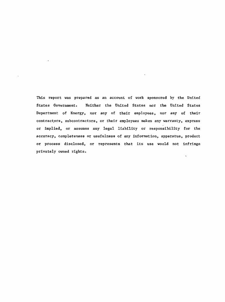
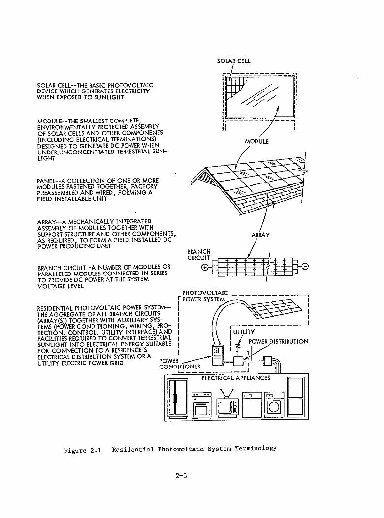