OPERATION AND ASSEMBLY MANUAL OF CENTRIFUGAL FANS …
13
OPERATION AND MONTAGE MANUAL NO.: MSB-VB/2020/V1 (valid since: 05.02.2020) Venture Industries Sp. z o.o. is not responsible for any damage caused by improper use of the fan and reserves the right to modify this document without informing the user. OPERATION AND ASSEMBLY MANUAL OF CENTRIFUGAL FANS WITH BELT DRIVE TYPE MSB-VB
Transcript of OPERATION AND ASSEMBLY MANUAL OF CENTRIFUGAL FANS …

OPERATION AND MONTAGE MANUAL NO.: MSB-VB/2020/V1 (valid since: 05.02.2020)
Venture Industries Sp. z o.o. is not responsible for any damage caused by improper use of the fan and reserves the right to modify this document without informing the user.
OPERATION AND ASSEMBLY MANUAL OF CENTRIFUGAL FANS WITH BELT DRIVE
TYPE MSB-VB
MSB-VB/2020/V1
2/13 tel. (22) 751 95 50 www.venture.pl fax. (22) 751 22 59
INTRODUCTION This manual covers fan listed on frontpage. It is source of information necessary for safe and proper use. Read this manual carefully before any use of the device, comply with it requirements and keep it in place with easy access for users and service. If case of any doubts about use of the fan, please contact with manufacturer.
Additional requirements about use of the unit can be found in electric motor documentation and markings - those requirements need to be met.
After receiving the device - check •whether the device is in compliance with order, •whether the data on the rating plate are the same as desired. •whether fan was not damaged during transport (e.g. there are no dents/cracks) •whether a motor documentation (containing manual) is attached In case of any irregularities, contact with your dealer or Venture Industries Sp. z o.o. service.
1. GENERAL INFORMATION 1.1 Information about device
The fan is a not completed machine within the meaning of the Machinery Directive 2006/42/WE (please refer to the manufacturer's declaration – Appendix D).
Fan is designed for use by trained, qualified adult persons in industrial environment. The fan is not designed for household or similar use.
The device is designed to transport clean air and air with dust - required contact with manufacturer. Do not transport the explosive mixtures, solid elements, liquids, substances that cause abrasion, chemically reactive compounds. Minimal temperature of transported medium is -20°C, maximum is determined on rating plate.
The fan must be protected from the weather (e.g. snow, rain, excessive sun radiation, lightning). The device is not designed to be installed outdoor. The fan surrounding cannot contain explosive atmospheres, substances causing abrasion, chemically aggressive substances, viscous substances, liquid, substances with high humidity. Maximum ambient temperature is determined on rating plate.
The device must not be exposed to radiation (such as microwave, UV, laser, x-ray).
The impeller has been balanced in accordance with minimum G6.3 class ISO 1940-1, and general construction of the fan in accordance with cat. BV-3 ISO 14694 Description of construction of the fan has been included in Appendix E. Additional information of the fan usage has been indicated on the device. Additional information have been included in Appendix A. 1.2 General risk and guidelines During entire fan life cycle pay particular attention to the risk and guidelines presented below: 1.2.1 moveable components
The fan is equipped with moveable components (impeller of the device, impeller of the motor). Contact with them may cause serious injury or death. The fan must not be used if covers (grids) and safety measures against contact with rotating parts have not been installed. 1.2.2 suction
The fan has high suction power. Clothing, hair, foreign particles, and even body elements can be easily sucked in. It is forbidden to approach the fan in “loose” clothing or reaching toward inlet of working fan and motor impeller. It need to be ensured, that no foreign body can be sucked in. 1.2.3 thrown elements
The air at the outlet of the fan has high energy. Elements sucked or placed inside the fan can be thrown with a high speed. The fan has stable, solid construction, but as a result of damage or improper use some parts (elements with high kinetic energy) may be thrown away. Make sure that before start and during operation of the fan there are no elements, that may be sucked in (pay special attention to fan inlet side) and there are no person in stream of transported medium (on inlet and outlet side). Do not approach in the immediate sorrounding of motor impeller. Do not use fan without proper inlet, outlet and moveable elements covers (grids).
Unit is not made as gas-tight. 1.2.4 sharp edges
During manufacturing the fan sharp edges was grinded. However the fan may have edges touching which may cause injury. We recommend the use of relevant protective gloves. 1.2.5. inertness
The fan has a high inertness. In case of no permanent fix turning on the fan will lead to it uncontrolled movement. The unit can be turn on only after proper installation. 1.2.6 noise
The sound pressure level is dependent on the operation point. Check the sound pressure level and if necessary use silencers and/or individual protection measures for personnel. 1.2.7 materials
In case of fire or transport of improper medium – fan parts can generate fumes hazardous to health. 1.2.8. environment
The fan can make over and under pressure. In areas where a specified air pressure and the quantity of air are required (e.g. in places with combustion) make sure that there would be no deficit/excess of air.

MSB-VB/2020/V1
tel. (22) 751 95 50 www.venture.pl fax. (22) 751 22 59 3/13
1.2.9 temperature (hot surfaces)
The housing and fan elements take the temperature of transported medium. During work (e.g. as a result of compression process) the temperature of medium, housing and fan components increase. Electric motor heat up to high temperatures (especially when overloaded/overheated). The appropriate steps need to be made to prevent from fire and burns caused of high temperatures. In case of fire – to extinguish a fire use fire extinguisher approved for electrical equipment and follow
recommendation of fire department.
1.2.10 unexpected start / connecting power supply Before undertaking any kind of work on fan (e.g. installation, maintenance and inspection, disassembly), it has to be completely and reliably disconnected (isolated) from power supply (check there is no voltage). It has to be ensured, that power supply will not be connected during work on fan and moveable parts are not moving.
Capacitor (only single phase fans) is still energized for certain period of time after turning off the power supply.
The appropriate steps need to be made in order to provide protection against electric shock and to prevent from access to electrical components by unauthorized person.
Fan is not equipped with control system – the connecting of power supply causes immediate start-up. The device is not equipped with system, that would permanently shut it down in case of temporary power supply loss. It has to be ensured, that any dangerous or unpermitted event does not occur in case of temporary loss of power supply. Thermal sensors installed in motor (if fitted) after tripping caused by motor overheat turn back to initial state after cooling down. It has to be ensured, that any dangerous or unpermitted event does not occur in case of action of thermal sensors and after motor cooling down. In case of impeller jamming – its unblocking may cause sudden movement. Appropriate steps need to be made in order to avoid impeller jamming. In case of impeller jamming, fan need to be completely disconnected from power supply and repaired. After disconnecting from power supply fan still works for certain time (moveable parts are moving) as a result of energy accumulation. 1.2.11 use
Improper installation and/or use may lead to damage of the device and occurrence of dangerous situation. The unit can by installed, maintained, dismantled and used only by qualified and authorized personnel, in accordance to safety rules and current regulations in the country of use (including proper electrical authorization). Personnel need to be familiar with reactions caused by the fan.
Using of fan in dismantled/uncompleted state is forbidden, e.g. without junction box cover.
During the works (e.g. maintenance, installation) the fans surrounding needt to be protected from bystanders approach.
Any modifications of the unit are forbidden. Complicated maintenance work (such as dismantling the motor or impeller) need to be made by Venture Industries Sp. z o.o. service or with it permission - according to additional guidance. Improper assembly may lead to reduce the fan parameters, damage the unit and lead to the dangerous situation. 1.2.12 Accumulation of dust
Prevent the accumulation of dust, sediment on and inside the fan. Dirt accumulated on: grids – reduce the fan parameters; impeller – may lose it balance; housing and motor – can reduce the cooling; hot surfaces (see 1.2.9) – may ignite. 1.2.13 explosive atmospheres
Contact of the fan with explosive atmospheres cause in ignition. It is forbidden to contact the fan with explosive atmospheres.
2. TRANSPORT AND STORAGE 2.1 transport and storage guidelines •The fan need to be transported and stored in original packaging, without excessive shocks. The device must be protected from weather conditions, transported and stored in dry, well ventilated, and free from substances harmful to the device areas. The fan cannot by transported and stored in areas with fertilizers, chlorinated lime, acids and other aggressive chemicals. Fan need to be protected against foreign body entrance. •Protect the fan against damage (including crush). After lifting unit it need to be put slowly. •Do not lift the unit by motor elements (e.g. eye bolt), impeller, protection net. During lifting the device must remain stable.
•Do not approach lifted device. In case of breaking, falling device may cause serious injury or death.
It is recommended that storage time does not exceed one year. After long storage, before installation check the fan. (section 5). 3. ASSEMBLY AND INSTALLATION 3.1 General information
During installation follow the guidelines contained in section 1.2
The fan is a machine not ready for use (within the meaning of the Machinery Directive 2006/42/WE - before use of the device ensure conformity with requirements of Machinery Directive 2006/42/WE. After installation the device must meet the requirements included in EN ISO 12100, EN ISO 13857, EN ISO 13850 and EN 60204-1 standards. Additional information is included in Manufacturer Declaration (Appendix D).
Before installation remove temporary items that protect fan during transport and storage (e.g. box, foil, inlet and outlet caps – do not remove any guards) – Starting the fan with those items could lead to damage of the fan. Make sure that the fan is not damaged.

MSB-VB/2020/V1
4/13 tel. (22) 751 95 50 www.venture.pl fax. (22) 751 22 59
Ensure that there are no foreign bodies (e.g. mounting elements, tools) inside fan and near of the unit, the fan is properly secured after installation (the cover of connection box is closed and secured, the connecting elements are properly tightened). Technical acceptance need to be carried out in accordance with Appendix B.
During mechanical connection special attention need to be paid to prevent from falling sold objects into fan, which would lead to it damage.
3.2 Assembly information
Fan need to by mounted in possition presented on Fig1., in horizontal motor shaft possition, with base (A) on bottom (Note: depending on model - fan outlet possition may be different than on diagram). All holes placed in the base have to be used. Ventilation installation need to be connected to fan inlet and/or outlet flange (all holes placed in flange need to be used). For mounting - fasteners secured from looseing need to be used.
Fig. 1
Where: A - base
Supporting construction has to be solid enough in order to carry the weight of the fan and generated vibration (including fan damage). The fan cannot be exposed to vibration.
Inlet and outlet covers need to be applied. Covers need to protect from touching the impeller according to ISO 13857.
Fan need to be secured from sucking foreign elements (see paragraph 1.2.3). Inlet and outlet covers must comply with IP20 (EN 60529). If there is still risk of sucking foreign objects - additional protection need to be used.
It is recommended to apply measures minimizing transmission of vibration from/to the fan. For fans mounted in flexible form - connecting on inlet and outlet side need to be also made in flexible form.
Keep safe distance between installed device and inflammable elements (special attention to hot surfaces of device need to be paid).
Keep safe distance between motor cooling impeller and obstacles (in accordance with motor documentation, but not less than on Fig. 2).
Measures protecting user from burn by hot elements need to be applied.
MSB-VB/2020/V1
tel. (22) 751 95 50 www.venture.pl fax. (22) 751 22 59 5/13
3.3 V-belt drive assembly guidelines 3.3.1. First start
Before starting any maintenance work, it is extremely important that any machine components are in a safe position which cannot be changed during maintenance work.
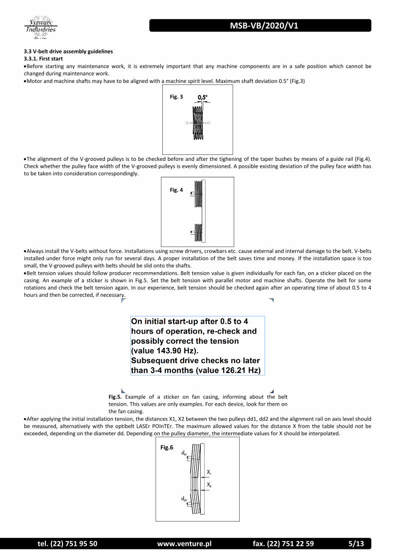
Motor and machine shafts may have to be aligned with a machine spirit level. Maximum shaft deviation 0.5° (Fig.3)
The alignment of the V-grooved pulleys is to be checked before and after the tighening of the taper bushes by means of a guide rail (Fig.4). Check whether the pulley face width of the V-grooved pulleys is evenly dimensioned. A possible existing deviation of the pulley face width has to be taken into consideration correspondingly.
Always install the V-belts without force. Installations using screw drivers, crowbars etc. cause external and internal damage to the belt. V-belts installed under force might only run for several days. A proper installation of the belt saves time and money. If the installation space is too small, the V-grooved pulleys with belts should be slid onto the shafts.
Belt tension values should follow producer recommendations. Belt tension value is given individually for each fan, on a sticker placed on the casing. An example of a sticker is shown in Fig.5. Set the belt tension with parallel motor and machine shafts. Operate the belt for some rotations and check the belt tension again. In our experience, belt tension should be checked again after an operating time of about 0.5 to 4 hours and then be corrected, if necessary.
Fig.5. Example of a sticker on fan casing, informing about the belt tension. This values are only examples. For each device, look for them on the fan casing.
After applying the initial installation tension, the distances X1, X2 between the two pulleys dd1, dd2 and the alignment rail on axis level should be measured, alternatively with the optibelt LASEr POInTEr. The maximum allowed values for the distance X from the table should not be exceeded, depending on the diameter dd. Depending on the pulley diameter, the intermediate values for X should be interpolated.
Fig. 3
Fig. 4
Fig.6
MSB-VB/2020/V1
6/13 tel. (22) 751 95 50 www.venture.pl fax. (22) 751 22 59
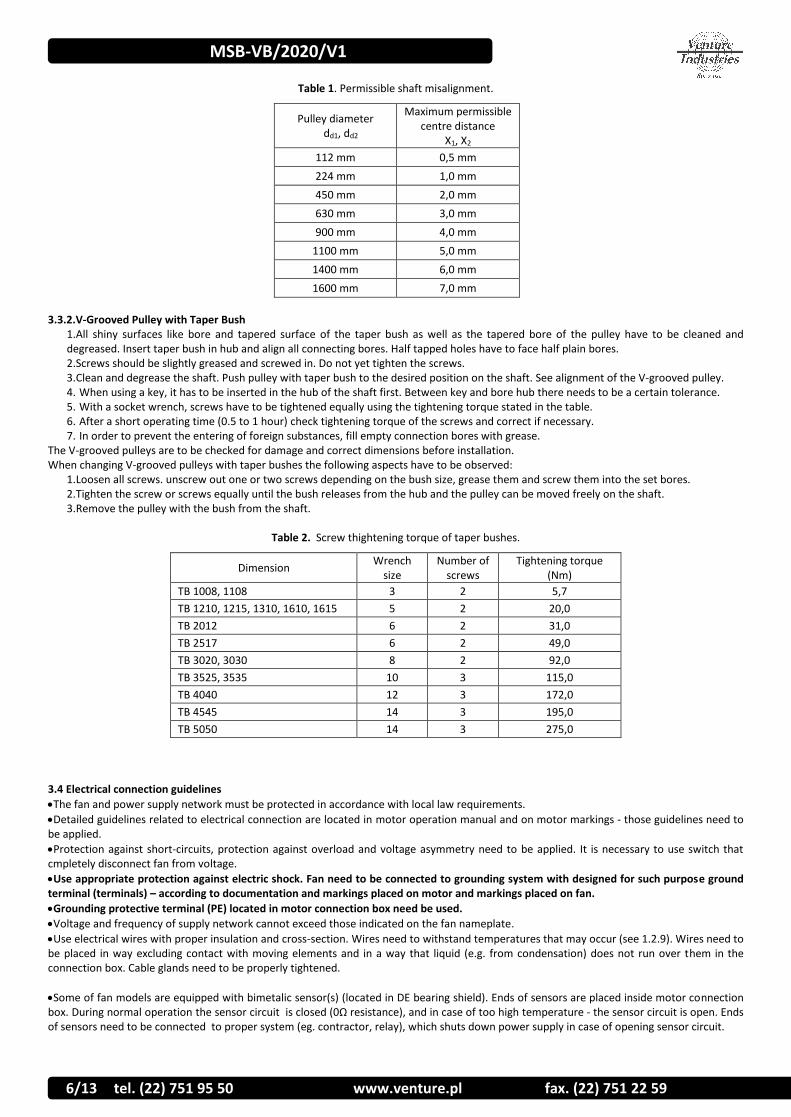
Table 1. Permissible shaft misalignment.
Pulley diameter dd1, dd2
Maximum permissible centre distance
X1, X2
112 mm 0,5 mm
224 mm 1,0 mm
450 mm 2,0 mm
630 mm 3,0 mm
900 mm 4,0 mm
1100 mm 5,0 mm
1400 mm 6,0 mm
1600 mm 7,0 mm
3.3.2.V-Grooved Pulley with Taper Bush
1.All shiny surfaces like bore and tapered surface of the taper bush as well as the tapered bore of the pulley have to be cleaned and degreased. Insert taper bush in hub and align all connecting bores. Half tapped holes have to face half plain bores. 2.Screws should be slightly greased and screwed in. Do not yet tighten the screws. 3.Clean and degrease the shaft. Push pulley with taper bush to the desired position on the shaft. See alignment of the V-grooved pulley. 4. When using a key, it has to be inserted in the hub of the shaft first. Between key and bore hub there needs to be a certain tolerance. 5. With a socket wrench, screws have to be tightened equally using the tightening torque stated in the table. 6. After a short operating time (0.5 to 1 hour) check tightening torque of the screws and correct if necessary. 7. In order to prevent the entering of foreign substances, fill empty connection bores with grease.
The V-grooved pulleys are to be checked for damage and correct dimensions before installation. When changing V-grooved pulleys with taper bushes the following aspects have to be observed:
1.Loosen all screws. unscrew out one or two screws depending on the bush size, grease them and screw them into the set bores. 2.Tighten the screw or screws equally until the bush releases from the hub and the pulley can be moved freely on the shaft. 3.Remove the pulley with the bush from the shaft.
Table 2. Screw thightening torque of taper bushes.
Dimension Wrench
size Number of
screws Tightening torque
(Nm)
TB 1008, 1108 3 2 5,7
TB 1210, 1215, 1310, 1610, 1615 5 2 20,0
TB 2012 6 2 31,0
TB 2517 6 2 49,0
TB 3020, 3030 8 2 92,0
TB 3525, 3535 10 3 115,0
TB 4040 12 3 172,0
TB 4545 14 3 195,0
TB 5050 14 3 275,0
3.4 Electrical connection guidelines
The fan and power supply network must be protected in accordance with local law requirements.
Detailed guidelines related to electrical connection are located in motor operation manual and on motor markings - those guidelines need to be applied.
Protection against short-circuits, protection against overload and voltage asymmetry need to be applied. It is necessary to use switch that cmpletely disconnect fan from voltage.
Use appropriate protection against electric shock. Fan need to be connected to grounding system with designed for such purpose ground terminal (terminals) – according to documentation and markings placed on motor and markings placed on fan.
Grounding protective terminal (PE) located in motor connection box need be used.
Voltage and frequency of supply network cannot exceed those indicated on the fan nameplate.
Use electrical wires with proper insulation and cross-section. Wires need to withstand temperatures that may occur (see 1.2.9). Wires need to be placed in way excluding contact with moving elements and in a way that liquid (e.g. from condensation) does not run over them in the connection box. Cable glands need to be properly tightened.
Some of fan models are equipped with bimetalic sensor(s) (located in DE bearing shield). Ends of sensors are placed inside motor connection box. During normal operation the sensor circuit is closed (0Ω resistance), and in case of too high temperature - the sensor circuit is open. Ends of sensors need to be connected to proper system (eg. contractor, relay), which shuts down power supply in case of opening sensor circuit.
MSB-VB/2020/V1
tel. (22) 751 95 50 www.venture.pl fax. (22) 751 22 59 7/13
Some of fan models are equipped with PTC sensors (located on motor windings). Ends of sensors are placed inside motor connection box. PTC sensor resistance grows rapidly with exceeding of permitted motor temperature value. Ends of sensor(s) placed inside connection box need to be connected to system (eg. relay), which shuts down power supply in case of exceeding permitted motor temperature. 3.5 Impeller rotation direction Make sure that after installation and during using the fan the impeller would rotate in correct direction. After mounting fan to proper construction, with special care taken and in accordance with sector 1 and 4, launch the fan in impulse way (less than 1 second) and check, if the impeller rotates in correct direction, generating airflow in proper direction (rotation direction need to be checked by checking the motor cooling impeller rotation direction). The work with impeller rotating in the wrong direction reduces fan parameters and may damage it. In case of improper impeller rotation, turn of power supply, wait until impeller stops and change proper power supplying wires in junction box. 4. USE 4.1 Use guidelines
Make sure that turning on of the fan does not make any hazard for personnel and property. Follow the guidelines featured in section 1.2.
The fan is designed for continuous operations (S1) – too high frequency of starting a fan may lead to motor overheat and damage.
Fan cannot work with voltage, frequency, current higher than shown on the fan nameplate (even if motor nameplate/manual allows it). Applying of higher frequency may cause motor damage or mechanical damage of the fan.
Use of fan with lowered voltage is not allowed - it may cause e.g. lack of fan start-up and motor overheating and damage.
The device cannot work with current consumption exceeding the value indicated on the nameplate.
In case of activation of any electrical protection, detection of damage, unit must by immediately turn out off use.
The device is adapted to work in certain range of characteristic. Too high volume flow rate of medium, start/work of device with completely opened inlet and/or outlet may lead to motor overheat caused by current consumption exceeding value on the rating plate (current consumed by fan grows as resistance of installation decreases)
Units work parameters (temperature of medium, ambient temperature, min and max flow rate....) refer to rated speed.
5. MAINTENANCE, REVIEW 5.1 Maintenance guidelines
During maintenance and review follow the guidelines contained in point 1.2
Fan need to be subject of regular review and maintenance (point 5.2).
Maintenance and review of motor need to be overtaken in accordance with motor documentation and markings. Exchange of motor bearings need to be made before the end of current bearing lifetime.
To clean fan construction use slightly damp delicate material. It is prohibited to use detergents, liquids under pressure and tools that may scratch the unit surface.
The fan need to be turned on at least once a month (minimum couple of impeller turns).
Ensure that there are no foreign bodies (e.g. assembly components, tools) near and inside the fan inled and outlet channel, the unit is clean, dry and secured after maintenance and review. After cleaning finishes, turn on the fan at max speed for 30 minutes.
During review special attention to the following need to be paid:
dust and dirt Prevent the accumulation of dust/dirt on and inside the fan. Dirt accumulated on: grids – may reduce the fan parameters; housing and motor – can reduce the cooling; hot surfaces –may ignite. Special attention must be paid to motor cooling impeller and its cover. Reduction of cooling ability may lead to overheat of motor without working of safety devices.
corrosion Corrosion of the fan may lead to mechanical damage of it. It is forbidden to use the fan if corrosion appears
overload Exceeding of nominal current may be caused by improper choice of fan, mechanical damage (e.g. impeller, bearing), improper electrical connection. Current value must be controlled, and if its growth is noticed, the reason need to be determined and device need to be repaired. Current value cannot exceed nominal value.
vibration
Excessive vibration may cause mechanical damage of the fan or it mounting construction. The vibration increase can indicate bearings damge or loss of impeller balance. Vibration value need to be controlled, and if its growth is noticed, the reason need to be determined and device must be repaired. Maximum vibration value on bearings (perpendicular to motor shaft) after fan installation cannot exceed value presented in table below:
rigidly mounted* flexibly monted*
peak r.m.s peak r.m.s.
6.4 mm/s 4.5 mm/s 8.8 mm/s 6.3 mm/s
*according to ISO 14694
belts tension Inappropriate belt tension can lead to excessive wear of belt drive and other elements of the fan. Too low belt tension causes vibration, noise and exccesive belt slip. Excessive belt tension causes additional load on bearings of impeller and motor and will reduce its service life. Applying recommended tension allows for long and reliable operation of the fan.
alignment and belts condition
Poor drive alignment can cause belts turning over or falling. In case of detect belts excessive wear, it is necessery to replace all with a new. Assembly of belts with different condition can affect the wrong operate of the fan. Too late belt replacement can leads to wear pulley grooves and bealt breaks. Broken belt can also damaged other parts of fan.

MSB-VB/2020/V1
8/13 tel. (22) 751 95 50 www.venture.pl fax. (22) 751 22 59
5.2 Review and maintenance
The set between routine checks and maintenance need to be determined by user, based on the observation of unit and specific conditions of use, in order to include specific work conditions. The set cannot be longer than introduced below
In the case of irregularities the device must be turn off and subjected to review, maintenance and possible repairs / cleaning (when dirt occurs). Examples of reasons for device to work in emergency mode are given in Appendix C.
Staff operating the device must be familiar with it normal working conditions. If the fan work differ from it normal working conditions it need to be turn off from work and inspected.
Detailed information about komponents and it tightening torque is available on request. Recommended daily review, not less frequently than once a week:
Device is undamaged, stable and works properly
There are not any leaks, smoke from motor
Device does not emit any untypical noise, and does not heat up excessively
Device is clean (general control), corrosion does not occur (general control)
Wires are not damaged
there are no untypical leaks from fan
Covers are in proper state and clean Monthly review
Fan current value is not higher than beginning value
The values of generated vibration did not increase (according to beginning value)
Device and covers are clean
Device is clean, filter is not clogged. Review once per 3 months, not less than 6 month and 3000 hours of work
Corrosion does not occur
Fasteners state is proper (they are properly tightened)
Security devices are working and set properly, protection against electrical shock is effective.
Motor insulation resistance value is correct
Structure is complete, components are not damaged (e.g. by abrasion)
Fan review made by Venture Industries Sp. z o.o. service is recommended.
6. REPAIR, WARRANTY Use only original spare parts and original accessories. Fan repairs need to be made by Venture Industries Sp. z o.o. service or outside, after manufacturer permission. Warrantee conditions are described in guarantee card. 7. DISMANTLING AND RECYCLING Disconnect unit from its power supply, and dismount according to the guidelines from section 1 of this instruction. Therefore, please deposit all left-over material and packaging in their corresponding recycling containers and hand in the replaced machines to the nearest handler of this type of waste product.

MSB-VB/2020/V1
tel. (22) 751 95 50 www.venture.pl fax. (22) 751 22 59 9/13
Appendix - A (Product indication)
[1] – product full name [2] – motor type [3] – motor power [4] – nominal current [5] – motor IP class [8] – nominal voltage [8] – power supply frequency [9] – nominal fan speed
[10]- motor insulation class [11] - weight [12] – max ambient temperature [13] – max temperature of transproted medium [14] – informetion of accordance with ErP Directive (if apply) [15] – serial number [16] – Art. No.
Additional information indicated on the device - arrow informing about correct direction of impeller rotation - arrow informing about correct air flow direction - indications related to safe use of device

MSB-VB/2020/V1
10/13 tel. (22) 751 95 50 www.venture.pl fax. (22) 751 22 59
Appendix B - (The device receipt form)
Before launch Check confirmation
Type and model of fan are in accordance with the order.
The fan is undamaged.
There is no foreign body inside fan, and the fan is clean.
The fan is reliably and solidly fixed in workplace.
The fan is properly leveled
Wires are properly tightened.
Ambient temperature and transported medium temperature are compatible with fan nameplate
Proper electrical protection is applied
Grounding of fan is applied.
Network power supply is compatible with fan power supply.
Power supply disconnecting switch is applied.
Personnel using the fan read and understood the operation and montage manual.
Proper inlet and outlet covers (grids) have been applied
Filter on inlet side is applied
Pulleys are tightened correctly.
Belts of the transmission are installed correctly.
Transmission covers were installed
Belts are tensioned correctly.
After fan launch (continuous work period minimum 30 minutes)
Readings and set of vibration measurement device has been written (they are available in future)
Readings and set of current measurement device has been written (they are available in future)
Value of current for each of phase does not exceed nominal one
The vibration value is not higher than permitted.

MSB-VB/2020/V1
tel. (22) 751 95 50 www.venture.pl fax. (22) 751 22 59 11/13
Appendix - C (EXAMPLES OF DEVICE FAULTY WORKING)
SYMPTOMS POSSIBLE REASON
Excessive vibration or noise
Used or damaged impeller
Fan levelled in wrong way
Dirt accumulated on impeller caused loss of balance;
Impeller loss of balance
Parts rubbing;
Damage or wear of bearings;
Damage of measurement system, that is responsible for signalization of excessive vibration.
Deformed motor shaft;
Loose of impeller fix screw, impeller is loose on motor shaft;
Loss of balance of motor impeller or damage of motor (wear/damage of bearing)
Motor overload
•Rubbing between fan impeller and housing; •Damage or wear of bearings; •Damage of motor windings (overheat, insulation degradation, insulation breakdown etc.); •Damage of switch or security system; •Failure of one of supply phases; •Exceeding of maximum motor speed; •Too low flow
Failed fan start-up
•Rubbing between fan impeller and housing or foreign body (e.g. tool left after installation); •Failure of one of supply phases; •Failure of start-up system, e.g. Y/D •Reset of security devices has not been made, wrong security device •Motor connected in wrong way or damaged
Too low supply voltage
Protective devices activation during fan
work and overheating
•Excessive start-up time •Motor overload
Motor launching done too often (thermal protection – if applied or overheating)
Improper set of protection system e.g. in system with PTC or thermocontact sensors (if applied) •Improper cross-section of power supply wires •Lack of sufficient motor cooling eg. dirt placed on motor cooling impeller (thermal protection – if applied or overheating)
Too low flow
Damage of device
Too low power supply frequency
Obstacles in ventilation installation
Damaged bearings
Too fast belts wear
Belt tension too low
Excessive pulley groove wear
Poor pulley alignment
Belt rubbing against or catching on protruding parts
Excessive heat
Excessive cold
Contamination by chemicals

MSB-VB/2020/V1
12/13 tel. (22) 751 95 50 www.venture.pl fax. (22) 751 22 59
Appendix - D (Declaration of Manufacturer)

MSB-VB/2020/V1
tel. (22) 751 95 50 www.venture.pl fax. (22) 751 22 59 13/13
Appendix - E (Schematic diagram of the fan)
General description (simplified)
A - base B - inlet C - inlet flange D - outlet E - outlet flange F - motor G - casing H - belt drive housing
1 – belt drive housing 2 - pulleys 3 – V-belts 4 - base 5 - motor 6 - impeller hub 7 - outlet flange 8 - casing 9 - inlet 10 – inlet flange
Casing (8), base (4), inlet flange (10), outlet flange (7) are made from carbon steel. Inlet (9) is made from aluminum / carbon steel. Connection elements are made from steel / stainless steel. For sealing - sealing paste and sealing tapes (e.g. EPDM) has been used, selected elements have been painted. Full list of components and materials used in fan can be provided on reasonable request.