Operating - Parts Towndownload.partstown.com/.../-/en_US/manuals/741-TF_spm.pdf · Operating...
27
Model No. 741-TF, 741-TCE & 741-TGB 2, 4, 8 & 12 Channel Series (Merlin II) Operating Instructions 355 East Kehoe Blvd. • Carol Stream, IL 60188 USA Telephone: 630-462-8800 • Fax : 630-462-1460 Toll Free: 1-800-PCASTLE www.princecastle.com Printed in 2004 Prince Castle Inc. 741-500FGISrevA Prince Castle’s second generation of Merlin Timers feature a new slim design which gives you mounting flexibility. The 740 Series Timers are designed so each channel can be programmed independently, and used simultaneously. The timers are simple to program and simple to use. The push of a button activates each channel, and a alarm and multi-colored flashing channel buttons alert the operator when timing is complete. TABLE OF CONTENTS Installation . . . . . . . . . . . . . . . . . . . . . . . . . . . . . . 2 Displays and Indicators . . . . . . . . . . . . . . . . . . . . 2 Controls . . . . . . . . . . . . . . . . . . . . . . . . . . . . . . . . 2 Programming . . . . . . . . . . . . . . . . . . . . . . . . . . . . 2 Operation . . . . . . . . . . . . . . . . . . . . . . . . . . . . . . . 4 Cleaning . . . . . . . . . . . . . . . . . . . . . . . . . . . . . . . . 4 Parts List . . . . . . . . . . . . . . . . . . . . . . . . . . . . . . . . 5 Exploded View . . . . . . . . . . . . . . . . . . . . . . . . . . . 5 Troubleshooting . . . . . . . . . . . . . . . . . . . . . . . . . . 6 Wiring Diagram . . . . . . . . . . . . . . . . . . . . . . . . . . . 6 Mode d’emploi . . . . . . . . . . . . . . . . . . . . . . . . . . . . 7 Betriebsanweisungen . . . . . . . . . . . . . . . . . . . . . . 12 Istruzioni per il funzionamento . . . . . . . . . . . . . . . . 17 Instrucciones de operación . . . . . . . . . . . . . . . . . . 22 Single Function Timers Channel Series Electrical 741-Series 230 Volts 50 – 60 Hz LIMITED WARRANTY This product is warranted to be free from defects in material and/or workmanship for a period of two years from date of original installation, not to exceed 30 months from date of shipment from our factory. Any component which proves to be faulty in material and/or workmanship will be replaced or repaired (at the option of Prince Castle, Inc.) without cost to the customer for parts or labor. This warranty is subject to the following exceptions/ conditions: • This equipment is portable, charges for on location service (e.g. trip charges and mileage) are not included in the provisions of this warranty. • Use of any non-genuine Prince Castle parts voids this warranty. All genuine Prince Castle replacement spare parts are warranted for ninety (90) days from date of purchase. • All work must be performed by an authorized Prince Castle Service Agency. Failure to do so will void this warranty. • Damage caused by carelessness, neglect, and/or abuse (e.g., dropping, tampering or altering parts), equipment damaged in shipment, by fire, flood or an act of God is not covered under this warranty.
Transcript of Operating - Parts Towndownload.partstown.com/.../-/en_US/manuals/741-TF_spm.pdf · Operating...
Model No. 741-TF, 741-TCE &741-TGB 2, 4, 8 & 12
Channel Series (Merlin II)
Operating Instructions
355 East Kehoe Blvd. • Carol Stream, IL 60188 USATelephone: 630-462-8800 • Fax : 630-462-1460
Toll Free: 1-800-PCASTLEwww.princecastle.com
Printed in 2004Prince Castle Inc.
741-500FGISrevA
Prince Castle’s second generation of Merlin Timers feature a new slim design which gives you mounting flexibility. The 740 Series Timers are designed so each channel can be programmed independently, and used simultaneously. The timers are simple to program and simple to use. The push of a button activates each channel, and a alarm and multi-colored flashing channel buttons alert the operator when timing is complete.
TABLE OF CONTENTSInstallation . . . . . . . . . . . . . . . . . . . . . . . . . . . . . . 2Displays and Indicators . . . . . . . . . . . . . . . . . . . . 2Controls . . . . . . . . . . . . . . . . . . . . . . . . . . . . . . . . 2Programming . . . . . . . . . . . . . . . . . . . . . . . . . . . . 2Operation . . . . . . . . . . . . . . . . . . . . . . . . . . . . . . . 4Cleaning . . . . . . . . . . . . . . . . . . . . . . . . . . . . . . . . 4Parts List . . . . . . . . . . . . . . . . . . . . . . . . . . . . . . . . 5Exploded View . . . . . . . . . . . . . . . . . . . . . . . . . . . 5Troubleshooting . . . . . . . . . . . . . . . . . . . . . . . . . . 6Wiring Diagram . . . . . . . . . . . . . . . . . . . . . . . . . . . 6Mode d’emploi . . . . . . . . . . . . . . . . . . . . . . . . . . . . 7Betriebsanweisungen . . . . . . . . . . . . . . . . . . . . . . 12Istruzioni per il funzionamento. . . . . . . . . . . . . . . . 17Instrucciones de operación . . . . . . . . . . . . . . . . . . 22
Single Function Timers
Channel Series
Electrical
741-Series230 Volts50 – 60 Hz
LIMITED WARRANTYThis product is warranted to be free from defects in material and/or workmanship for a period of two years from date of original installation, not to exceed 30 months from date of shipment from our factory.
Any component which proves to be faulty in material and/or workmanship will be replaced or repaired (at the option of Prince Castle, Inc.) without cost to the customer for parts or labor.
This warranty is subject to the following exceptions/ conditions:• This equipment is portable, charges for on location
service (e.g. trip charges and mileage) are not included in the provisions of this warranty.
• Use of any non-genuine Prince Castle parts voids this warranty. All genuine Prince Castle replacement spare parts are warranted for ninety (90) days from date of purchase.
• All work must be performed by an authorized Prince Castle Service Agency. Failure to do so will void this warranty.
• Damage caused by carelessness, neglect, and/or abuse (e.g., dropping, tampering or altering parts), equipment damaged in shipment, by fire, flood or an act of God is not covered under this warranty.

741-500FGISrevA 2
INSTALLATION1. After you have removed the timer from the carton,
inspect the unit for signs of damage. If there is damage to the unit:
• Notify carrier within 24 hours after delivery.
• Save carton and packing materials for inspection purposes.
• Contact your local dealer or, if purchased directly, the Prince Castle Customer Sales Department at 1-800-722-7853 to arrange for a replacement to be sent.
2. Verify that all parts have been received. Bracket Mounting screws provided.
3. To mount the timer, place mounting brackets in desired location. Scribe location of mounting holes, center punch, and drill holes. Attach timer to mounting brackets placing star washer between bracket and timer.
DISPLAYS AND INDICATORS
CONTROLS
PROGRAMMING1. To program, press and hold the PRINCE
CASTLE logo for six seconds. The TIME display changes from ---- to Prog, and a beep will sound. See figure 1.
figure 1
2. Select and press the timer channel to be programmed. The LED indicator for the selected button will turn yellow and a beep will sound. The selected channel number will be displayed in the CHANNEL display, the current programmed time for that channel will be displayed in the TIME display, and the time value will indicate either H:M OR M:S. See figure 2.
TIMEDisplay
Shows the time for the selected channel number.
CHANNELDisplay
Shows the channel number selected and in use. (The 741-T2 model does not have this display.)
H:M Indicates the time value is in Hours and Minutes.
M:S Indicates that the time value is in Minutes and Seconds.
LEDIndicators
Located above each channel timer button, these lights change color depending on the stage of the countdown. Green = first 70% of countdown,Yellow = next 20% of countdown, Red = last 10% of countdown.
Channel(Timer)
The 741-T2 has 2 channels, the 741-T4 has 4 channels, the 741-T8 has 8 channels and the 741T12 has 12 channels.
SCAN/UPARROW
In the program mode, it increases time values for each channel. In the Run Mode, it is used in conjunction with logo button to increase the volume.
SCAN/DOWNARROW
In the program mode, it decreases time values for each channel. In the Run Mode, it is used in conjunction with logo button to decrease the volume.
PRINCECASTLE
Logo
Activates Program Mode and used to adjust the alarm sound level.

3 741-500FGISrevA
figure 2
3. To change the program time for the selected channel, use the SCAN/UP Arrow or the SCAN/ DOWN Arrow button.
IMPORTANT: To change from Minutes and Seconds M:S to Hours and Minutes H:M. Press and hold the SCAN/UP Button. When the display reaches 59:59 it will automatically change to 1:00 Hour and the LED will switch from M:S to H:M. The program value for the H:M indicator is from 1:00 hour to 17 hours: 59 minutes. See figures 3 and 4.
figure 3
figure 4
4. To program another channel, press the desired channel button. Repeat programming procedures in steps 2 and 3. See figure 5.
figure 5
5. When finished programming each desired channel, momentarily press the PRINCE CASTLE logo to end the Program Mode. This saves the program changes you have made for all channels. See figure 6.
figure 6
6. You can change the sound level of the alarm in RUN MODE. Press and hold the PRINCE CASTLE logo; then, within six seconds, press either the SCAN UP Arrow button or the SCAN DOWN Arrow button. The SCAN UP Arrow button adjusts the sound level to the louder alarm, and the SCAN DOWN Arrow button adjusts the sound level to the lower alarm. See figure 7.
figure 7
741-500FGISrevA 4
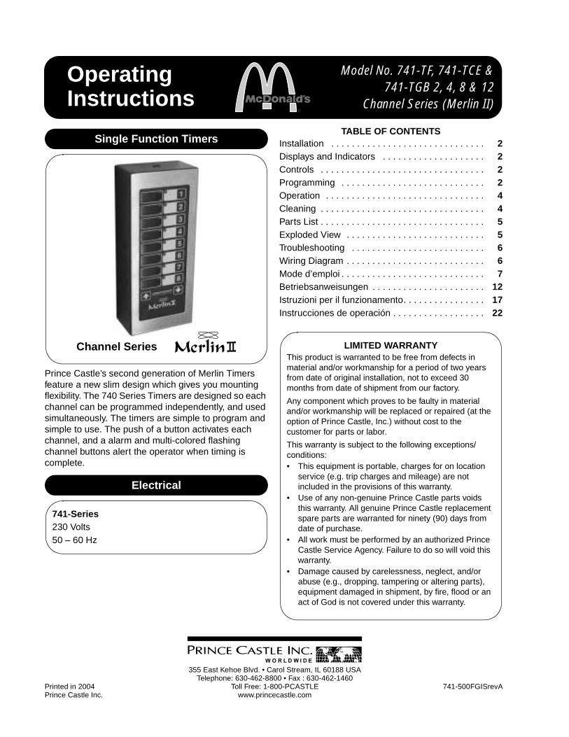
OPERATION1. Press a channel button to activate a timing
cycle. (All channels can be activated and running at the same time.) The time channel number with the least amount of time remaining will be displayed in the CHANNEL display, its time remaining will countdown in the TIME display, and the time value M:S or H:M will be illuminated. See figure 8.
figure 8
2. Press the desired channel button three times within five seconds to cancel an active timing cycle.
IMPORTANT: The channel timer button’s multi-colored LED indicator shows the status of the timer. The indicator has three colors: green, yellow, and red. The LED will be green during the first 70% of the countdown. It changes to yellow during the next 20% of the countdown. It will be red during the final 10% of the countdown, and will start flashing red once the time has run out.
3. The timer will countdown from the programmed value to zero. At zero, the display flashes End and the alarm sounds. See figure 9.
figure 9
IMPORTANT: There are three indicators that signal the operator when the timing cycle is complete: The CHANNEL display shows the channel associated with the alarm. The TIME display shows End. The LED indicator in the channel button flashes red.
4. When the timing cycle is complete, and the alarm sounds, press the channel button with the flashing red indicator to cancel the alarm. See figure 10.
figure 10
5. The scan feature is used to check the time values on other active channels. There are two different ways to scan active channels. Press the SCAN/UP or SCAN/DOWN button or press any of the active timer CHANNEL buttons. If no other button is pressed within 5 seconds, the display will change to show the timer with the least amount of time left. See figure 11.
figure 11
CLEANING1. Do not allow grease to build up on the timer, wipe
it down daily with clean damp cloth.
IMPORTANT: Do not use abrasive or chemical cleaners on your timer, this may cause damage to the overlay.
5 741-500FGISrevA
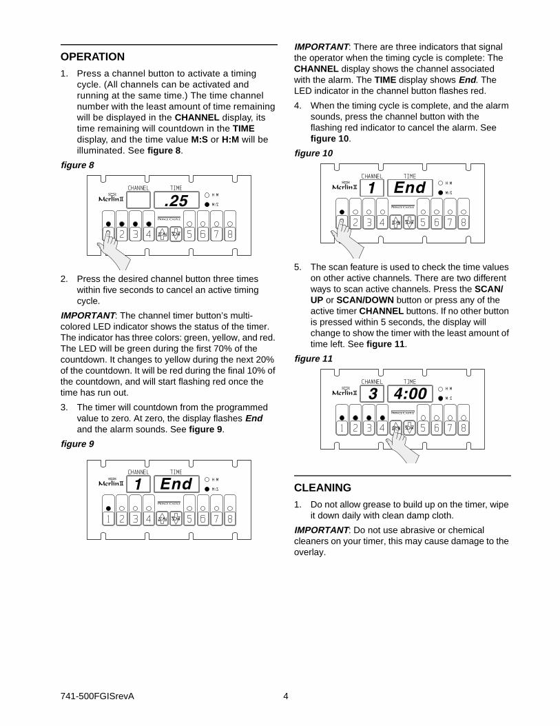
PARTS LIST
EXPLODED VIEW
Item Part Number Description7 88-653-2-4SA Speaker Assy.
10 741-021 I.C. Connector11 85-101-04S Power Supply PCB12 740-9S PCB, Main (T2)
740-225S PCB, Main (T4, T8 & T12)15 735-241S Mounting Bracket Kit16 70-048 Knob17 735-240S Switch Panel Assy. (T2)
735-211S Switch Panel Assy. (T4)740-026S Switch Panel Assy. (T8)735-208S Switch Panel Assy. (T12)
19 94-301 Label20 86-226 Spacer24 69-079S Rivet (Pkg. of 2)— 72-200-1S Line Cord (CE) Not Shown— 72-200-2S Line Cord (GB) Not Shown
16
15
10
16
15
17
20
7
19
24
11
12

741-500FGISrevA 6
TROUBLESHOOTING GUIDE
WIRING DIAGRAM 741-T2
PROBLEM CAUSE SOLUTION
A. No displays or indicators lit. Unit unplugged.Store’s circuit breaker blown.Defective transformer.
Circuit inoperable.
Plug unit in.Reset breaker.Replace Power Supply Board.
Replace Main Circuit Board.
B. Absence of Audio Alarm. Speaker inoperable.
Circuit inoperable.
Replace Speaker.
Replace Main Circuit Board.
C. Unit will not enter program mode. Display does not show “Prog”.
All channels are still counting.
Logo Switch inoperable.
Wait until channels are in stop mode.
Replace Switch Panel.
D. Unit enters program mode. Display shows “Prog”, but cannot change times.
The channel is still counting.
Arrow Switch inoperable.Circuit inoperable.
Wait until channel is in stop mode.
Replace Switch Panel.Replace Main Circuit Board.
E. Unable to start, stop, or store timer presets in program mode. Missing or abnormal characters in displays.
Circuit inoperable. Replace Switch Panel. If problem persists, replace Main Circuit Board.
YE
LL
OW
SPEAKER
MEMBRANE SWITCHMAIN PCB
RED
BLACK
POWER SUPPLY PCB
GROUND
GRN/YEL
BLUE
BROWNPOWER INLET
SPEAKER
BL
AC
K

7 741-500FGISrevA
INSTALLATION1. Après avoir extrait le minuteur de son emballage,
vérifier qu’il est en bon état. En cas de dommages de l’appareil:
• Notifier le transporteur dans les 24 heures qui suivent la livraison.
• Conserver le carton et les matériaux d’emballage à des fins d’examen.
• Contacter le revendeur local ou, en cas d’achat direct, le Service à la clientèle Prince Castle au (+1) 800-722-7853 afin d’obtenir l’envoi d’un appareil de rechange.
2. Vérifier que toutes les pièces ont été reçues. Les vis de fixation des supports sont fournies.
3. Pour poser le minuteur, placer les supports de fixation à l’endroit souhaité. Tracer l’emplacement des trous de fixation, marquer au pointeau et percer. Poser les supports de fixation en plaçant une rondelle éventail entre le support et l’appareil.
ÉCRANS ET INDICATEURS
COMMANDES
PROGRAMMATION1. Pour programmer, tenir la touche logo PRINCE
CASTLE enfoncée pendant six secondes. L’écran TIME passe de ---- à Prog et un bip sonore est audible. Voir figure 1.
figure 1
2. Appuyer sur la touche du canal minuteur à programmer. Le voyant lumineux de la touche sélectionnée s’allume en jaune et un bip sonore est audible. Le numéro du canal sélectionné s’affiche sur l’écran CHANNEL, la durée actuellement programmée pour ce canal s’affiche sur l’écran TIME, cette valeur s’affichant en mode H:M OU M:S. Voir figure 2.
ÉcranTIME
Affiche la durée pour le canal sélectionné.
ÉcranCHANNEL
Affiche le numéro de canal sélectionné et en cours d’utilisation (le modèle 741-T2 ne comporte pas cet écran).
H:M Indique que la durée est affichée en Heures et Minutes.
M:S Indique que la durée est affichée en Minutes et Secondes.
Voyantslumineux
Placés au-dessus de chaque touche de canal, ces voyants changent de couleur en fonction de l’avancement du compte à reboursVert = premiers 70% du compte à rebours, Jaune = 20% suivants du compte à rebours, Rouge = derniers 10% du compte à rebours.
Canal(Minuteur)
Le 741-T2 comporte 2 canaux, le 741-T4 4 canaux, le 741-T8 8 canaux et le 741T12 12 canaux.
FLÈCHE SCAN/HAUT
En mode Programmation, cette touche permet d’augmenter la valeur de durée d’un canal. En mode Exécution, elle s’utilise en association avec la touche logo pour augmenter le volume.
FLÈCHE SCAN/BAS
En mode Programmation, cette touche permet de diminuer la valeur de durée d’un canal. En mode Exécution, elle s’utilise en association avec la touche logo pour diminuer le volume.
Logo PRINCECASTLE
Cette touche active le mode Programmation et sert à régler le niveau sonore de l’alarme.
741-500FGISrevA 8
figure 2
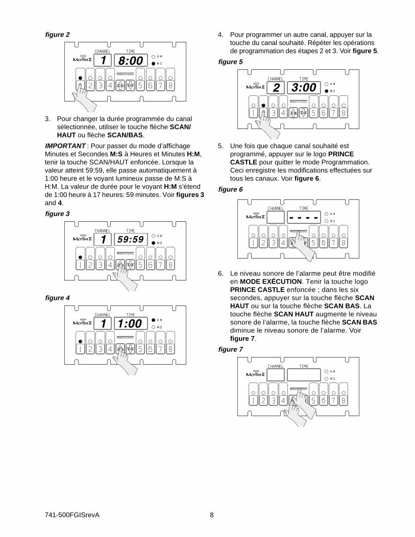
3. Pour changer la durée programmée du canal sélectionnée, utiliser le touche flèche SCAN/HAUT ou flèche SCAN/BAS.
IMPORTANT : Pour passer du mode d’affichage Minutes et Secondes M:S à Heures et Minutes H:M, tenir la touche SCAN/HAUT enfoncée. Lorsque la valeur atteint 59:59, elle passe automatiquement à 1:00 heure et le voyant lumineux passe de M:S à H:M. La valeur de durée pour le voyant H:M s’étend de 1:00 heure à 17 heures: 59 minutes. Voir figures 3 and 4.
figure 3
figure 4
4. Pour programmer un autre canal, appuyer sur la touche du canal souhaité. Répéter les opérations de programmation des étapes 2 et 3. Voir figure 5.
figure 5
5. Une fois que chaque canal souhaité est programmé, appuyer sur le logo PRINCE CASTLE pour quitter le mode Programmation. Ceci enregistre les modifications effectuées sur tous les canaux. Voir figure 6.
figure 6
6. Le niveau sonore de l’alarme peut être modifié en MODE EXÉCUTION. Tenir la touche logo PRINCE CASTLE enfoncée ; dans les six secondes, appuyer sur la touche flèche SCAN HAUT ou sur la touche flèche SCAN BAS. La touche flèche SCAN HAUT augmente le niveau sonore de l’alarme, la touche flèche SCAN BAS diminue le niveau sonore de l’alarme. Voir figure 7.
figure 7

9 741-500FGISrevA
FONCTIONNEMENT1. Appuyer sur un bouton de canal pour activer le
cycle de minutage correspondant (tous les canaux peuvent être activés et s’exécuter en même temps). L’écran CHANNEL affiche le numéro du canal minuteur dont la durée restante est la plus courte, l’écran TIME affiche le compte à rebours correspondant et le voyant de valeur de durée M:S ou H:M s’allume selon le cas. Voir figure 8.
figure 8
2. Appuyer sur la touche du canal souhaité trois fois dans les cinq secondes pour annuler un cycle de minutage actif.
IMPORTANT : Le voyant lumineux multicolore d’une touche de canal minuteur indique l’état du minuteur. Ce voyant a trois couleurs : vert, jaune et rouge. Le voyant s’affiche en vert pendant les premiers 70% du compte à rebours. Il passe au jaune durant les 20% suivants du compte à rebours. Il s’allume en rouge durant les derniers 10% du compte à rebours et clignote en rouge une fois que la durée est écoulée.
3. Le minuteur compte à rebours depuis la valeur programmée jusqu’à zéro. À zéro, l’écran affiche End en clignotant et l’alarme sonore se déclenche. Voir figure 9.
figure 9
IMPORTANT : Il y trois indicateurs signalant à l’opérateur la fin de cycle du minuteur : L’écran CHANNEL affiche le numéro de canal associé à l’alarme. L’écran TIME affiche End. Le voyant lumineux de la touche du canal clignote en rouge.
4. À la fin du cycle du minuteur, l’alarme sonore se déclenche ; appuyer sur la touche de canal dont le voyant clignote en rouge pour couper l’alarme. Voir figure 10.
figure 10
5. La fonction de consultation permet de vérifier les valeurs de durée des autres canaux actifs. Il y a deux moyens différents de consulter les canaux actifs. Appuyer sur la touche SCAN/HAUT ou SCAN/BAS ou sur la touche de l’un quelconque des canaux minuteurs actifs. Si aucune autre touche n’est enfoncée dans les 5 secondes, l’écran revient à l’affichage du minuteur de durée restante la plus courte. Voir figure 11.
figure 11
NETTOYAGE1. Ne pas laisser de graisse s’accumuler sur le
minuteur, l’essuyer chaque jour avec un chiffon humide propre.
IMPORTANT : Pour éviter d’endommager le revêtement, ne pas utiliser de détergent abrasif ou chimique sur le minuteur.

741-500FGISrevA 10
NOMENCLATURE DES PIÈCES
VUE ÉCLATÉE
Repère Référence Description7 88-653-2-4SA Haut-parleur
10 741-021 Connecteur11 85-101-04S Carte d’alimentation12 740-9S Carte principale (T2)
740-225S Carte principale (T4, T8 et T12)15 735-241S Supports de fixation16 70-048 Bouton de serrage17 735-240S Panneau de commande (T2)
735-211S Panneau de commande (T4)740-026S Panneau de commande (T8)735-208S Panneau de commande (T12)
19 94-301 Étiquette20 86-226 Bague d’espacement24 69-079S Rivet (paquet de 2)— 72-200-1S Cordon d’alimentation (CE) Non représenté— 72-200-2S Cordon d’alimentation (GB) Non représenté
16
15
10
16
15
17
20
7
19
24
11
12
11 741-500FGISrevA
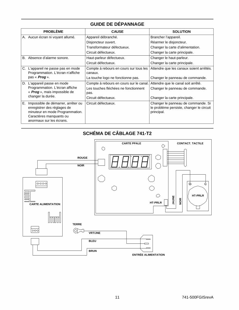
GUIDE DE DÉPANNAGE
SCHÉMA DE CÂBLAGE 741-T2
PROBLÈME CAUSE SOLUTION
A. Aucun écran ni voyant allumé. Appareil débranché.Disjoncteur ouvert.Transformateur défectueux.
Circuit défectueux.
Brancher l’appareil.Réarmer le disjoncteur.Changer la carte d’alimentation.
Changer la carte principale.
B. Absence d’alarme sonore. Haut-parleur défectueux.
Circuit défectueux.
Changer le haut-parleur.
Changer la carte principale.
C. L’appareil ne passe pas en mode Programmation. L’écran n’affiche pas « Prog ».
Compte à rebours en cours sur tous les canaux.La touche logo ne fonctionne pas.
Attendre que les canaux soient arrêtés.
Changer le panneau de commande.
D. L’appareil passe en mode Programmation. L’écran affiche « Prog », mais impossible de changer la durée.
Compte à rebours en cours sur le canal.Les touches fléchées ne fonctionnent pas.Circuit défectueux.
Attendre que le canal soit arrêté.Changer le panneau de commande.
Changer la carte principale.
E. Impossible de démarrer, arrêter ou enregistrer des réglages de minuteur en mode Programmation. Caractères manquants ou anormaux sur les écrans.
Circuit défectueux. Changer le panneau de commande. Si le problème persiste, changer le circuit principal.
JAU
NE
HT-PRLR
CONTACT. TACTILECARTE PPALE
ROUGE
NOIR
CARTE ALIMENTATION
TERRE
VRT/JNE
BLEU
BRUNENTRÉE ALIMENTATION
HT-PRLR
NO
IR
741-500FGISrevA 12
EINBAU1. Nach der Entnahme des Zeitgebers aus dem
Karton muss er auf Anzeichen von Schäden untersucht werden. Falls der Zeitgeber beschädigt ist:
• Den Spediteur innerhalb von 24 Stunden nach der Zustellung verständigen.
• Den Karton und das Verpackungsmaterial zu Inspektionszwecken aufheben.
• Den örtlichen Händler verständigen, bzw. bei Direktkauf die Prince Castle Kundendienstabteilung unter der Rufnummer 1-800-722-7853 verständigen und die Lieferung eines Ersatzproduktes arrangieren.
2. Überprüfen, ob alle Teile erhalten wurden. Die Befestigungsschrauben für die Halterung werden mitgeliefert.
3. Zur Befestigung des Zeitgebers die Befestigungshalterungen an der gewünschten Stelle anbringen. Die Lage der Befestigungslöcher anzeichnen, körnen und die Löcher vorbohren. Den Zeitgeber an den Befestigungshalterungen anbringen und Sternscheiben zwischen Halterung und Zeitgeber anbringen.
ANZEIGEN UND KONTROLLLEUCHTEN
BEDIENELEMENTE
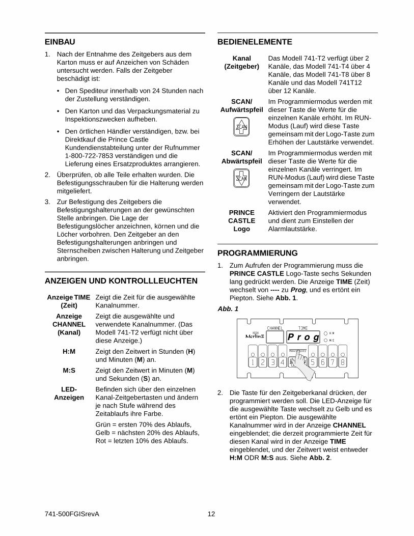
PROGRAMMIERUNG1. Zum Aufrufen der Programmierung muss die
PRINCE CASTLE Logo-Taste sechs Sekunden lang gedrückt werden. Die Anzeige TIME (Zeit) wechselt von ---- zu Prog, und es ertönt ein Piepton. Siehe Abb. 1.
Abb. 1
2. Die Taste für den Zeitgeberkanal drücken, der programmiert werden soll. Die LED-Anzeige für die ausgewählte Taste wechselt zu Gelb und es ertönt ein Piepton. Die ausgewählte Kanalnummer wird in der Anzeige CHANNEL eingeblendet; die derzeit programmierte Zeit für diesen Kanal wird in der Anzeige TIME eingeblendet, und der Zeitwert weist entweder H:M ODR M:S aus. Siehe Abb. 2.
Anzeige TIME (Zeit)
Zeigt die Zeit für die ausgewählte Kanalnummer.
Anzeige CHANNEL
(Kanal)
Zeigt die ausgewählte und verwendete Kanalnummer. (Das Modell 741-T2 verfügt nicht über diese Anzeige.)
H:M Zeigt den Zeitwert in Stunden (H) und Minuten (M) an.
M:S Zeigt den Zeitwert in Minuten (M) und Sekunden (S) an.
LED-Anzeigen
Befinden sich über den einzelnen Kanal-Zeitgebertasten und ändern je nach Stufe während des Zeitablaufs ihre Farbe.
Grün = ersten 70% des Ablaufs, Gelb = nächsten 20% des Ablaufs, Rot = letzten 10% des Ablaufs.
Kanal (Zeitgeber)
Das Modell 741-T2 verfügt über 2 Kanäle, das Modell 741-T4 über 4 Kanäle, das Modell 741-T8 über 8 Kanäle und das Modell 741T12 über 12 Kanäle.
SCAN/Aufwärtspfeil
Im Programmiermodus werden mit dieser Taste die Werte für die einzelnen Kanäle erhöht. Im RUN-Modus (Lauf) wird diese Taste gemeinsam mit der Logo-Taste zum Erhöhen der Lautstärke verwendet.
SCAN/Abwärtspfeil
Im Programmiermodus werden mit dieser Taste die Werte für die einzelnen Kanäle verringert. Im RUN-Modus (Lauf) wird diese Taste gemeinsam mit der Logo-Taste zum Verringern der Lautstärke verwendet.
PRINCE CASTLE
Logo
Aktiviert den Programmiermodus und dient zum Einstellen der Alarmlautstärke.

13 741-500FGISrevA
Abb. 2
3. Um die Programmzeit für den ausgewählten Kanal zu ändern, muss die Taste SCAN/Aufwärtspfeil oder SCAN/Abwärtspfeil benutzt werden.
WICHTIG: Um von Minuten und Sekunden M:S zu Stunden und Minuten H:M umzuschalten, die Taste SCAN/Aufwärtspfeil drücken. Wenn die Anzeige 59:59 erreicht, ändert sie sich automatisch zu 1:00 Stunde und die LED wechselt von M:S zu H:M. Der Programmwert für H:M kann zwischen 1:00 und 17 Stunden: 59 Minuten liegen. Siehe Abb. 3 und 4.
Abb. 3
Abb. 4
4. Um einen anderen Kanal zu programmieren, muss die gewünschte Kanaltaste gedrückt werden. Die Programmierverfahren in Schritten 2 und 3 oben wiederholen. Siehe Abb. 5.
Abb. 5
5. Nach Abschluss der Progammierung für die einzelnen Kanäle kurz die PRINCE CASTLE Logo-Taste drücken, um den Programmiermodus zu beenden. Dadurch werden die an allen Kanälen vorgenommenen Programmänderungen gespeichert. Siehe Abb. 6.
Abb. 6
6. Die Lautstärke des Alarms im RUN-MODUS kann auch geändert werden. Die PRINCE CASTLE Logo-Taste gedrückt halten und innerhalb von sechs Sekunden entweder die Taste SCAN/Aufwärtspfeil oder die Taste SCAN/Abwärtspfeil drücken. Die Taste SCAN/Aufwärtspfeil stellt die Lautstärke der oberen Alarms und die Taste SCAN/Abwärtspfeil die Lautstärke des unteren Alarms ein. Siehe Abb. 7.
Abb. 7

741-500FGISrevA 14
BETRIEB1. Um einen Zeitgeberzyklus zu beginnen, eine
Kanaltaste drücken. (Alle Kanäle können gleichzeitig aktiviert werden und laufen.) Die Zeitgeberkanalnummer, die als erstes ablaufen wird (kürzeste verbleibende Dauer), wird auf der Anzeige CHANNEL eingeblendet; die verbleibende Zeitdauer läuft auf der Anzeige TIME ab und der Zeitwert M:S oder H:M ist beleuchtet. Siehe Abb. 8.
Abb. 8
2. Die gewünschte Kanaltaste innerhalb von fünf Sekunden drei Mal drücken, um einen aktiven Zeitgeberzyklus abzubrechen.
WICHTIG: Die mehrfarbige LED-Kontrollleuchte der Kanalzeitgebertaste zeigt den Status des Zeitgebers an. Die Kontrollleuchte kann drei Farben haben: Grün, Gelb und Rot. Die LED ist während der ersten 70% des Zeitablaufs grün. In den nächsten 20% des Zeitablaufs leuchtet sie gelb auf. Während der letzten 10% des Zeitablaufs leuchtet sie rot und beginnt zu blinken, sobald die Zeitdauer abgelaufen ist.
3. Der Zeitgeber zählt vom programmierten Wert bis auf Null herunter. Bei Null blinkt auf der Anzeige End (Ende) und der Alarm ertönt. Siehe Abb. 9.
Abb. 9
WICHTIG: Es gibt drei Kontrollleuchten, die dem Bediener ausweisen, wann ein Zeitgeberzyklus abgelaufen ist: Die Anzeige CHANNEL (Kanal) zeigt den Kanal des jeweiligen Alarms. Die Anzeige TIME (Zeit) enthält End (Ende). Die LED-Kontrollleuchte in der Kanaltaste blinkt rot.
4. Nach Abschluss des Zeitgeberzyklus ertönt der Alarm und es muss die Kanaltaste mit der rot blinkenden Kontrollleuchte gedrückt werden, um den Alarm zu quittieren. Siehe Abb. 10.
Abb. 10
5. Die Scan-Funktion dient zum Prüfen der Zeitwerte in anderen aktiven Kanälen. Aktive Kanäle können auf zwei unterschiedliche Weisen gescannt werden. Die Taste SCAN/Aufwärtspfeil oder SCAN/Abwärtspfeil drücken oder eine Taste CHANNEL (Kanal) für einen der aktiven Zeitgeberkanäle drücken. Falls innerhalb von fünf Sekunden keine andere Taste gedrückt wird, wechselt die Anzeige zum Zeitgeber mit der geringsten verbleibenden Ablaufdauer. Siehe Abb. 11.
Abb. 11
REINIGUNG1. Nicht zulassen, dass sich Fett auf dem Zeitgeber
ablagert. Dieses täglich mit einem feuchten Tuch abwischen.
WICHTIG: Um Schäden an der Deckschicht zu verhindern, keine scheuernden Reiniger oder Chemikalien auf dem Zeitgeber anwenden.

15 741-500FGISrevA
TEILELISTE
EXPLOSIONSDARSTELLUNG
POS. TEILENUMMER BESCHREIBUNG7 88-653-2-4SA Lautsprecher
10 741-021 Steckverbinder11 85-101-04S Netzteil, Hauptsteuerkarte12 740-9S Hauptversorgung, Hauptsteuerkarte (T2)
740-225S Hauptversorgung, Hauptsteuerkarte (T4, T8 u. T12)15 735-241S Befestigungshalterung, Satz16 70-048 Taste17 735-240S Tastenfeld (T2)
735-211S Tastenfeld (T4)740-026S Tastenfeld (T8)735-208S Tastenfeld (T12)
19 94-301 Schild20 86-226 Distanzstück24 69-079S Niete (je 2 Stück)— 72-200-1S Netzkabel (CE), nicht dargestellt— 72-200-2S Netzkabel (GB), nicht dargestellt
16
15
10
16
15
17
20
7
19
24
11
12

741-500FGISrevA 16
ANLEITUNG ZUR FEHLERSUCHE
SCHALTPLAN 741-T2
PROBLEM URSACHE LÖSUNG
A. Anzeige oder Kontrollleuchten nicht an.
Einheit nicht an Stromversorgung angeschlossen.
Trennschalter ist gefallen.Trafo ist ausgefallen.Schaltkreis ist funktionsunfähig.
Einheit anschließen.
Trennschalter zurücksetzen.Netzversorgungskarte ersetzen.Hauptsteuerkarte ersetzen.
B. Kein akustischer Alarm. Lautsprecher ist funktionsunfähig.Schaltkreis ist funktionsunfähig.
Lautsprecher ersetzen.Hauptsteuerkarte ersetzen.
C. Einheit kann nicht in den Programmiermodus geschaltet werden. Anzeige enthält nicht “Prog”.
Alle Kanäle laufen noch ab.
Logo-Taste ist defekt.
Warten, bis die Kanäle im Stopp-Modus sind.Tastenfeld ersetzen.
D. Einheit ruft Programmiermodus auf. Anzeige enthält “Prog”, aber Zeitwerte können nicht geändert werden.
Der Kanal läuft noch ab.
Pfeiltaste ist defekt.Schaltkreis ist funktionsunfähig.
Warten, bis der Kanal im Stopp-Modus sind.
Tastenfeld ersetzen.Hauptsteuerkarte ersetzen.
E. Starten, Stoppen oder Speichern der Zeitgeberwerte im Programmiermodus ist nicht möglich. Fehlende oder ungewöhnliche Zeichen auf den Anzeigen.
Schaltkreis ist funktionsunfähig. Tastenfeld ersetzen. Falls sich das Problem nicht beseitigen lässt, die Hauptsteuerkarte ersetzen.
GE
LB
LAUTSPRECHER
MEMBRANTASTEHAUPTSTEUERKARTE
ROT
SCHWARZ
NETZTEIL, HAUPTSTEUERKARTE
MASSE
GRÜN/GELB
BLAU
BRAUNNETZANSCHLUSS
LAUTSPRECHER
SC
HW
AR
Z
17 741-500FGISrevA
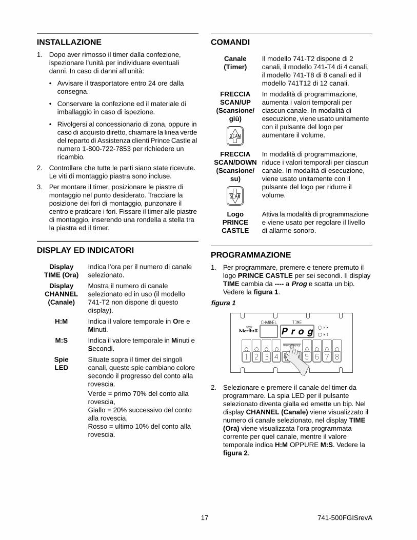
INSTALLAZIONE1. Dopo aver rimosso il timer dalla confezione,
ispezionare l’unità per individuare eventuali danni. In caso di danni all’unità:
• Avvisare il trasportatore entro 24 ore dalla consegna.
• Conservare la confezione ed il materiale di imballaggio in caso di ispezione.
• Rivolgersi al concessionario di zona, oppure in caso di acquisto diretto, chiamare la linea verde del reparto di Assistenza clienti Prince Castle al numero 1-800-722-7853 per richiedere un ricambio.
2. Controllare che tutte le parti siano state ricevute. Le viti di montaggio piastra sono incluse.
3. Per montare il timer, posizionare le piastre di montaggio nel punto desiderato. Tracciare la posizione dei fori di montaggio, punzonare il centro e praticare i fori. Fissare il timer alle piastre di montaggio, inserendo una rondella a stella tra la piastra ed il timer.
DISPLAY ED INDICATORI
COMANDI
PROGRAMMAZIONE1. Per programmare, premere e tenere premuto il
logo PRINCE CASTLE per sei secondi. Il display TIME cambia da ---- a Prog e scatta un bip. Vedere la figura 1.
figura 1
2. Selezionare e premere il canale del timer da programmare. La spia LED per il pulsante selezionato diventa gialla ed emette un bip. Nel display CHANNEL (Canale) viene visualizzato il numero di canale selezionato, nel display TIME (Ora) viene visualizzata l’ora programmata corrente per quel canale, mentre il valore temporale indica H:M OPPURE M:S. Vedere la figura 2.
DisplayTIME (Ora)
Indica l’ora per il numero di canale selezionato.
DisplayCHANNEL (Canale)
Mostra il numero di canale selezionato ed in uso (il modello 741-T2 non dispone di questo display).
H:M Indica il valore temporale in Ore e Minuti.
M:S Indica il valore temporale in Minuti e Secondi.
SpieLED
Situate sopra il timer dei singoli canali, queste spie cambiano colore secondo il progresso del conto alla rovescia. Verde = primo 70% del conto alla rovescia,Giallo = 20% successivo del conto alla rovescia, Rosso = ultimo 10% del conto alla rovescia.
Canale(Timer)
Il modello 741-T2 dispone di 2 canali, il modello 741-T4 di 4 canali, il modello 741-T8 di 8 canali ed il modello 741T12 di 12 canali.
FRECCIASCAN/UP
(Scansione/giù)
In modalità di programmazione, aumenta i valori temporali per ciascun canale. In modalità di esecuzione, viene usato unitamente con il pulsante del logo per aumentare il volume.
FRECCIASCAN/DOWN (Scansione/
su)
In modalità di programmazione, riduce i valori temporali per ciascun canale. In modalità di esecuzione, viene usato unitamente con il pulsante del logo per ridurre il volume.
LogoPRINCECASTLE
Attiva la modalità di programmazione e viene usato per regolare il livello di allarme sonoro.

741-500FGISrevA 18
figura 2
3. Per cambiare l’ora di programmazione per il canale selezionato, usare i pulsanti a freccia SCAN/UP (Scansione/su) o SCAN/ DOWN (Scansione/giù).
IMPORTANTE: per cambiare da Minuti e Secondi M:S ad Ore e Minuti H:M. Premere e tenere premuto il pulsante SCAN/UP (Scansione/su). Quando il display raggiunge 59:59, cambia automaticamente su 1:00 Ora e la spia LED passa da M:S a H:M. Il valore di programmazione per l’indicatore H:M va da 1:00 ora a 17 ore: 59 minuti. Vedere le figures 3 e 4.
figura 3
figura 4
4. Per programmare un altro canale, premere il pulsante del canale desiderato. Ripetere le procedure di programmazione indicate nella fasi 2 e 3. Vedere la figura 5.
figura 5
5. Al termine della programmazione dei singoli canali desiderati, premere temporaneamente il logo PRINCE CASTLE per terminare la modalità di programmazione. Questo salva le modifiche di programmazione apportate per tutti i canali. Vedere la figura 6.
figura 6
6. È possibile cambiare il livello sonoro dell’allarme nella MODALITÀ DI ESECUZIONE. Premere e tenere premuto il logo PRINCE CASTLE; quindi entro sei secondi, premere il pulsante a freccia SCAN UP (Scansione/su) o SCAN DOWN (Scansione/giù). Il pulsante a freccia SCAN UP (Scansione/su) aumenta il volume del livello sonoro, mentre il pulsante a freccia SCAN DOWN (Scansione/giù) lo riduce. Vedere la figura 7.
figura 7

19 741-500FGISrevA
FUNZIONAMENTO1. Premere il pulsante di un canale per attivare un
ciclo di temporizzazione (tutti i canali possono essere attivati ed eseguiti contemporaneamente). Il numero del canale temporale con un valore temporale residuo minimo viene visualizzato nel display CHANNEL, il tempo restante viene indicato con conto alla rovescia nel display TIME e viene illuminato il valore temporale M:S o H:M. Vedere la figura 8.
figura 8
2. Premere tre volte il pulsante del canale desiderato, entro cinque secondi, per annullare un ciclo di temporizzazione attivo.
IMPORTANTE: la spia LED a più colori del pulsante del timer del canale riporta lo stato del timer. L’indicatore ha tre colori: verde, giallo e rosso. La spia LED appare verde durante il primo 70% del conto alla rovescia. Diventa gialla durante il 20% successivo e diventa infine rossa durante il restante 10% del conto alla rovescia; comincia quindi a lampeggiare allo scadere del tempo.
3. Il timer effettua il conto alla rovescia dal valore programmato a zero. A zero, il display lampeggia End (Fine) e scatta l’allarme. Vedere la figura 9.
figura 9
IMPORTANTE: vi sono tre indicatori che segnalano all’operatore il completamento del ciclo di temporizzazione: Il display CHANNEL mostra il canale associato all’allarme. Il display TIME mostra End (Fine). La spia LED nel pulsante del canale lampeggia di colore rosso.
4. Al completamento del ciclo di temporizzazione scatta l’allarme; premere il pulsante del canale con l’indicatore rosso lampeggiante per annullare l’allarme. Vedere la figura 10.
figura 10
5. La funzione di scansione viene usata per controllare i valori temporali sugli altri canali attivi. Esistono due modi per effettuare la scansione dei canali attivi. Premere il pulsante SCAN/UP (Scansione su) o SCAN/DOWN (Scansione/giù) o premere uno dei pulsanti CHANNEL (Canale) dei timer attivi. Se non si premono altri pulsanti entro 5 secondi, il display mostra il timer con il valore temporale residuo minimo. Vedere la figura 11.
figura 11
PULITURA 1. Evitare la formazione di grasso sul timer; pulirlo
ogni giorno con un panno pulito ed inumidito.
IMPORTANTE: non usare solventi abrasivi o chimici sul timer, onde evitare di danneggiarne la finitura.
741-500FGISrevA 20
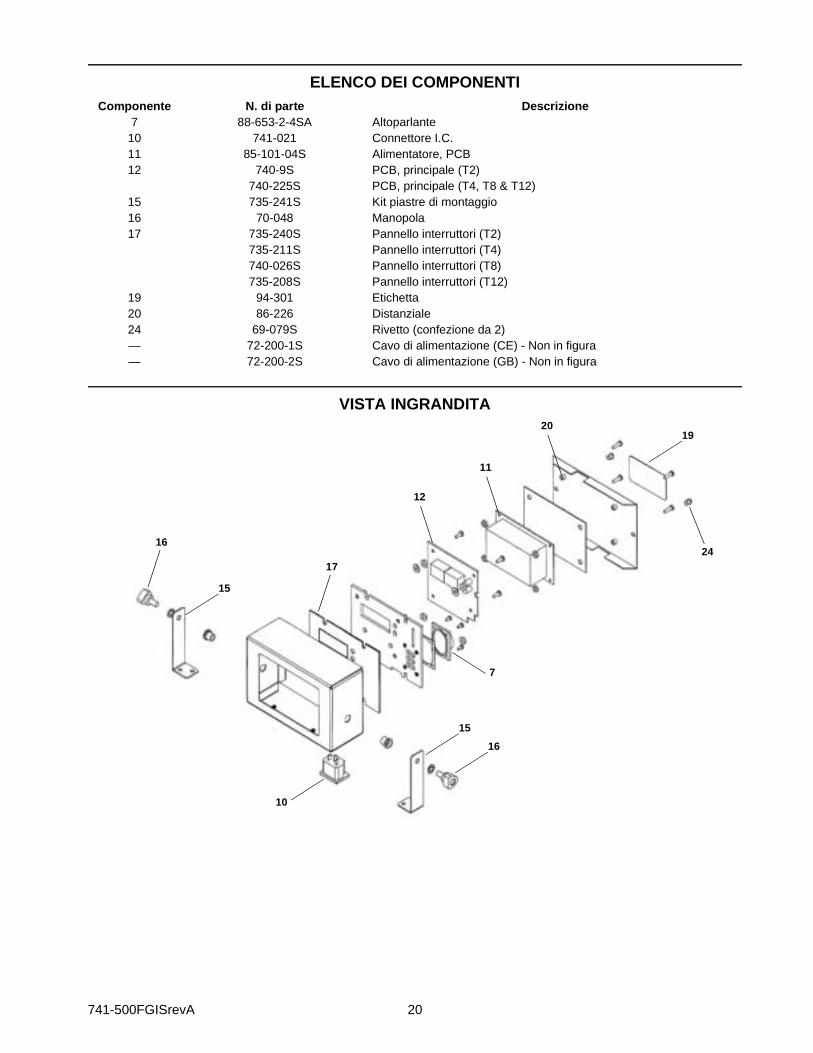
ELENCO DEI COMPONENTI
VISTA INGRANDITA
Componente N. di parte Descrizione7 88-653-2-4SA Altoparlante
10 741-021 Connettore I.C.11 85-101-04S Alimentatore, PCB12 740-9S PCB, principale (T2)
740-225S PCB, principale (T4, T8 & T12)15 735-241S Kit piastre di montaggio16 70-048 Manopola17 735-240S Pannello interruttori (T2)
735-211S Pannello interruttori (T4)740-026S Pannello interruttori (T8)735-208S Pannello interruttori (T12)
19 94-301 Etichetta20 86-226 Distanziale 24 69-079S Rivetto (confezione da 2)— 72-200-1S Cavo di alimentazione (CE) - Non in figura— 72-200-2S Cavo di alimentazione (GB) - Non in figura
16
15
10
16
15
17
20
7
19
24
11
12

21 741-500FGISrevA
GUIDA ALLA SOLUZIONE DEI PROBLEMI
SCHEMA ELETTRICO 741-T2
PROBLEMA CAUSA SOLUZIONE
A. Nessun display o indicatore acceso. Unità staccata.Interruttore automatico del negozio fuso.Trasformatore difettoso.Circuito non funzionante.
Collegare l’unità.Ripristinare l’interruttore.Sostituire la scheda dell’alimentatore.
Sostituire la scheda del circuito principale.
B. Assenza di allarme audio. Altoparlante non funzionante.Circuito non funzionante.
Sostituire l’altoparlante.Sostituire la scheda del circuito principale.
C. L’unità non passa alla modalità di programmazione. Il display non mostra “Prog”.
Tutti i canali continuano a contare.Interruttore Logo non funzionante.
Attendere fin quando tutti i canali passano alla modalità di arresto.
Sostituire il pannello degli interruttori.
D. L’unità passa alla modalità di programmazione. Il display mostra “Prog”, ma non cambia valore temporale.
Il canale continua a contare.
Pulsante a freccia non funzionante.Circuito non funzionante.
Attendere fin quando il canale passa alla modalità di arresto.Sostituire il pannello degli interruttori.
Sostituire la scheda del circuito principale.
E. Impossibile avviare, arrestare o memorizzare i valori prestabiliti del timer in modalità di programmazione. Caratteri mancanti o anomali nei display.
Circuito non funzionante. Sostituire il pannello degli interruttori. Se il problema continua, sostituire la scheda del circuito principale.
GIA
LL
O
ALTOPARLANTE
INTERRUTTORE A MEMBRANAPCB, PRINCIPALE
ROSSO
NERO
ALIMENTATORE, PCB
TERRA
VERDE/GIALLO
BLU
MARRONEINGRESSO ALIMENTAZIONE
ALTO-PARLANTE
NE
RO
741-500FGISrevA 22
INSTALACIÓN1. Luego de que haya sacado el temporizador de la
caja, inspeccione la unidad y verifique que no esté dañada. En caso de que la unidad haya sufrido algún daño:
• Infórmele al transportista dentro de las 24 horas posteriores a la entrega.
• Guarde la caja y los materiales de embalaje para propósitos de inspección.
• Comuníquese con su distribuidor local o, si la compró directamente, con el Departamento de Servicio al Cliente de Prince Castle al 1-800-722-7853 para coordinar el envío de otra unidad.
2. Verifique que recibió todas las piezas. Se incluyen los pernos de montaje para el soporte.
3. Para instalar el temporizador, coloque los soportes de montaje en la ubicación deseada. Marque la ubicación de los orificios de montaje, centre el punzón y perfore. Acople el temporizador a los soportes de montaje, colocando una arandela de estrella entre ambos.
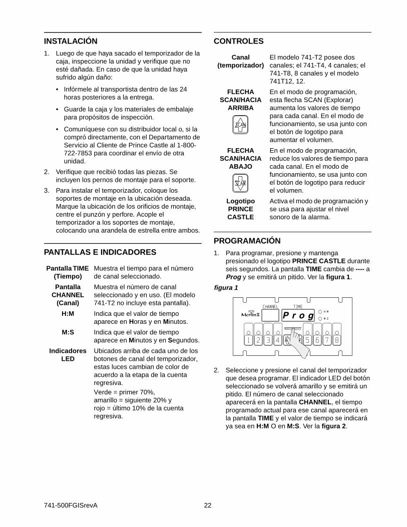
PANTALLAS E INDICADORES
CONTROLES
PROGRAMACIÓN1. Para programar, presione y mantenga
presionado el logotipo PRINCE CASTLE durante seis segundos. La pantalla TIME cambia de ---- a Prog y se emitirá un pitido. Ver la figura 1.
figura 1
2. Seleccione y presione el canal del temporizador que desea programar. El indicador LED del botón seleccionado se volverá amarillo y se emitirá un pitido. El número de canal seleccionado aparecerá en la pantalla CHANNEL, el tiempo programado actual para ese canal aparecerá en la pantalla TIME y el valor de tiempo se indicará ya sea en H:M O en M:S. Ver la figura 2.
Pantalla TIME (Tiempo)
Muestra el tiempo para el número de canal seleccionado.
Pantalla CHANNEL
(Canal)
Muestra el número de canal seleccionado y en uso. (El modelo 741-T2 no incluye esta pantalla).
H:M Indica que el valor de tiempo aparece en Horas y en Minutos.
M:S Indica que el valor de tiempo aparece en Minutos y en Segundos.
Indicadores LED
Ubicados arriba de cada uno de los botones de canal del temporizador, estas luces cambian de color de acuerdo a la etapa de la cuenta regresiva. Verde = primer 70%, amarillo = siguiente 20% y rojo = último 10% de la cuenta regresiva.
Canal (temporizador)
El modelo 741-T2 posee dos canales; el 741-T4, 4 canales; el 741-T8, 8 canales y el modelo 741T12, 12.
FLECHA SCAN/HACIA
ARRIBA
En el modo de programación, esta flecha SCAN (Explorar) aumenta los valores de tiempo para cada canal. En el modo de funcionamiento, se usa junto con el botón de logotipo para aumentar el volumen.
FLECHA SCAN/HACIA
ABAJO
En el modo de programación, reduce los valores de tiempo para cada canal. En el modo de funcionamiento, se usa junto con el botón de logotipo para reducir el volumen.
Logotipo PRINCE CASTLE
Activa el modo de programación y se usa para ajustar el nivel sonoro de la alarma.

23 741-500FGISrevA
figura 2
3. Para cambiar el tiempo programado para el canal seleccionado, use el botón de la flecha SCAN/HACIA ARRIBA o el de la flecha SCAN/HACIA ABAJO.
IMPORTANTE: Para cambiar de minutos y segundos M:S a horas y minutos H:M: Presione y mantenga presionado el botón SCAN/HACIA ARRIBA. Cuando la pantalla llegue a 59:59, cambiará automáticamente a 1:00 hora y el LED cambiará de M:S a H:M. El valor de programa para el indicador H:M va desde 1:00 hora a 17 horas con 59 minutos. Ver las figuras 3 and 4.
figura 3
figura 4
4. Para programar otro canal, presione el botón del canal deseado. Repita los pasos 2 y 3 del procedimiento de programación antes mencionado. Ver la figura 5.
figura 5
5. Cuando termine de programar cada canal deseado, presione momentáneamente el logotipo PRINCE CASTLE para finalizar el modo de programación y, así, guardar los cambios de programación que realizó para todos los canales. Ver la figura 6.
figura 6
6. Puede cambiar el nivel sonoro de la alarma en el MODO DE FUNCIONAMIENTO. Presione y mantenga presionado el logotipo PRINCE CASTLE; luego, dentro de los siguientes seis segundos, presione una de las flechas SCAN, HACIA ARRIBA O HACIA ABAJO. La flecha SCAN/HACIA ARRIBA ajusta el nivel sonoro de la alarma hasta el nivel más alto y la flecha SCAN/HACIA ABAJO lo ajusta hasta el nivel más bajo. Ver la figura 7.
figura 7

741-500FGISrevA 24
OPERACIÓN1. Presione un botón de canal para activar un ciclo
de temporización. (Todos los canales se pueden activar y funcionar al mismo tiempo). El número de canal que posea la menor cantidad de tiempo restante aparecerá en la pantalla CHANNEL, su tiempo restante se contará regresivamente en la pantalla TIME y se encenderá M:S o H:M para indicar el formato del valor de tiempo. Ver la figura 8.
figura 8
2. Presione tres veces en cinco segundos el botón del canal deseado para cancelar un ciclo de temporización activo.
IMPORTANTE: El indicador LED multicolor del botón de canal del temporizador muestra el estado del temporizador. El indicador tiene tres colores: verde, amarillo y rojo. El LED estará de color verde durante el primer 70% de la cuenta regresiva, cambia a amarillo durante el siguiente 20% y a rojo durante el 10% final de la cuenta regresiva, y comenzará a parpadear en rojo una vez que el tiempo se haya acabado.
3. El temporizador contará partiendo del valor programado hasta cero. Cuando llegue a cero, aparecerá End (Fin) en la pantalla y sonará la alarma. Ver la figura 9.
figura 9
IMPORTANTE: Existen tres indicadores que le avisan al operador una vez que el ciclo se ha completado: La pantalla CHANNEL muestra el canal asociado con la alarma. En la pantalla TIME aparece End. El indicador LED del botón de canal se enciende de color rojo y parpadea.
4. Cuando el ciclo de temporización esté completo y suene la alarma, presione el botón de canal con el indicador parpadeando en rojo para cancelar la alarma. Ver la figura 10.
figura 10
5. La función de exploración se usa para verificar los valores de tiempo de los otros canales activos. Existen dos formas distintas de explorar los canales activos. Presione el botón SCAN/HACIA ARRIBA o SCAN/HACIA ABAJO o cualquiera de los botones de CANAL del temporizador activos. Si no se presionan otros botones dentro de 5 segundos, la pantalla cambia y muestra el temporizador con la menor cantidad de tiempo restante. Ver la figura 11.
figura 11
LIMPIEZA1. No deje que se acumule grasa en el
temporizador; límpielo a diario con un paño húmedo y limpio.
IMPORTANTE: No use limpiadores abrasivos o químicos en el temporizador, ya que esto puede dañar el recubrimiento.

25 741-500FGISrevA
LISTA DE PIEZAS
VISTA DETALLADA
Item Part Number Description7 88-653-2-4SA Conjunto de altavoz
10 741-021 Conector11 85-101-04S Tarjeta de circuito impreso del suministro de energía eléctrica12 740-9S Tarjeta de circuito impreso principal (T2)
740-225S Tarjeta de circuito impreso principal (T4, T8 y T12)15 735-241S Juego de soporte de montaje16 70-048 Perilla17 735-240S Conjunto de panel de conexiones (T2)
735-211S Conjunto de panel de conexiones (T4)740-026S Conjunto de panel de conexiones (T8)735-208S Conjunto de panel de conexiones (T12)
19 94-301 Etiqueta20 86-226 Separador24 69-079S Remache (paquete de 2)— 72-200-1S Cordón de alimentación (CE). No se muestra— 72-200-2S Cordón de alimentación (RU). No se muestra
16
15
10
16
15
17
20
7
19
24
11
12

741-500FGISrevA 26
GUÍA DE SOLUCIÓN DE PROBLEMAS
DIAGRAMA DE CABLEADO DEL MODELO 741-T2
PROBLEMA CAUSA SOLUCIÓN
A. No se encienden pantallas ni indicadores.
La unidad está desenchufada.El disyuntor de la tienda está quemado.El transformador está defectuoso.El circuito está inutilizable.
Enchufe la unidad.Reajuste el disyuntor.Reemplace el tablero de alimentación.Reemplace el tablero de circuitos principal.
B. Ausencia de alarma audible. El altavoz está inutilizable.El circuito está inutilizable.
Reemplace el altavoz.Reemplace el tablero de circuitos principal.
C. La unidad no ingresa al modo de programación. “Prog” no aparece en pantalla.
Los canales aún están contando.
El interruptor de logotipo está inutilizable.
Espere hasta que los canales estén en modo detenido.Reemplace el panel de conexiones.
D. La unidad ingresa al modo de programación. Aparece “Prog” en la pantalla, pero los tiempos no se pueden modificar.
El canal aún está contando.
El interruptor de flecha está inutilizable.El circuito está inutilizable.
Espere hasta que el canal estén en modo detenido.Reemplace el panel de conexiones.Reemplace el tablero de circuitos principal.
E. No se puede iniciar, detener ni almacenar los valores preestablecidos del temporizador en el modo de programación. Caracteres faltantes o anormales en las pantallas.
El circuito está inutilizable. Reemplace el panel de conexiones. Si el problema persiste, reemplace el tablero de circuitos principal.
AM
AR
ILL
O
ALTAVOZ
INTERRUPTOR DE MEMBRANATARJETA DE CIRCUITO
IMPRESO PRINCIPAL
ROJO
NEGRO
TARJETA DE CIRCUITO IMPRESO DEL SUMINISTRO DE ENERGÍA ELÉCTRICA
TIERRA
VDE/AMA
AZUL
CAFÉTOMA DE CORRIENTE
ALTAVOZ
NE
GR
O

355 East Kehoe Blvd. • Carol Stream, IL 60188 USATelephone: 630-462-8800 • Fax : 630-462-1460
Toll Free: 1-800-PCASTLEwww.princecastle.com
Printed in 2004Prince Castle Inc.
741-500FGISrevA


![PrivacyDB V2.0 Certification Report - Common Criteria · Certification Report Page 7 [Figure-3], [Figure-4] is an API-based operating environment. Applications that are installed](https://static.fdocuments.in/doc/165x107/5f045e6e7e708231d40da2d8/privacydb-v20-certification-report-common-criteria-certification-report-page.jpg)