OPERATING MANUAL LOW-VOLTAGE DISCONNECT LVD1U200 SERIES · operating manual low-voltage disconnect...
14
OPERATING MANUAL LOW-VOLTAGE DISCONNECT LVD1U200 SERIES www.unipowerco.com Manual No. LVD1U200-2 © 2013 UNIPOWER LLC All Rights Reserved 07/13 lvd1u200-man-Rev2.indd NORTH AMERICA • 3900 Coral Ridge Drive, Coral Springs, Florida 33065, USA • Tel: +1 954-346-2442 • Fax: +1 954-340-7901 • [email protected] EUROPE • Parkland Business Centre, Chartwell Road, Lancing BN15 8UE, ENGLAND • Tel: +44(0)1903 768200 • Fax: +44(0)1903 764540 • [email protected]
Transcript of OPERATING MANUAL LOW-VOLTAGE DISCONNECT LVD1U200 SERIES · operating manual low-voltage disconnect...

OPERATING MANUALLOW-VOLTAGE DISCONNECT
LVD1U200 SERIES
www.unipowerco.com
Manual No. LVD1U200-2 © 2013 UNIPOWER LLCAll Rights Reserved07/13 lvd1u200-man-Rev2.indd
NORTH AMERICA • 3900 Coral Ridge Drive, Coral Springs, Florida 33065, USA • Tel: +1 954-346-2442 • Fax: +1 954-340-7901 • [email protected] • Parkland Business Centre, Chartwell Road, Lancing BN15 8UE, ENGLAND • Tel: +44(0)1903 768200 • Fax: +44(0)1903 764540 • [email protected]

Page 2
LVD1U200 SERIESOPERATING MANUAL
Manual No. lvd1u200-2 lvd1u200-man-Rev2-0713.indd
CONTENTS1.0 INTRODUCTION ...................................................................................................42.0 FEATURES ..............................................................................................................53.0 PRODUCT LINE .....................................................................................................54.0 SAFETY WARNINGS.............................................................................................55.0 WARRANTY (summary) ........................................................................................66.0 UNPACKING AND INSPECTION .........................................................................67.0 SPECIFICATIONS ..................................................................................................78.0 SAFETY AND INDUSTRY STANDARDS ............................................................89.0 DESCRIPTION OF OPERATION ..........................................................................810.0 FRONT PANEL DESCRIPTION ............................................................................911.0 REAR PANEL DESCRIPTION ..............................................................................912.0 FORM C RELAY CONTACTS .............................................................................1113.0 INSTALLATION ...................................................................................................1214.0 SETUP AND TESTING ........................................................................................13APPENDIX .....................................................................................................................14

Page 3
LVD1U200 SERIESOPERATING MANUAL
Manual No. lvd1u200-2 lvd1u200-man-Rev2-0713.indd
FIGURESFigure 1. LVD1U200 Low-Voltage Disconnect Panel ..................................................4Figure 2. LVD1U200 Rear Panel ...................................................................................4Figure 3. Simplified Schematic Diagram .......................................................................8Figure 4. Alarm LED Detail ..........................................................................................8Figure 5a. Connection Schematic – Battery RTN connected to RTN(OUT) ..................9Figure 5b. Connection Schematic – Battery RTN connected to System RTN ................9Figure 6. Input Bus Bar Detail .....................................................................................10Figure 7. Wire-Wrap Terminal Connections ................................................................11
Page 4
LVD1U200 SERIESOPERATING MANUAL
Manual No. lvd1u200-2 lvd1u200-man-Rev2-0713.indd
OPERATING MANUALLOW-VOLTAGE DISCONNECT LVD1U200 SERIES
1.0 INTRODUCTION
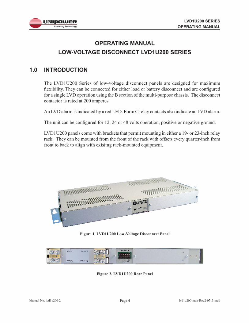
The LVD1U200 Series of low-voltage disconnect panels are designed for maximum flexibility. They can be connected for either load or battery disconnect and are configured for a single LVD operation using the B section of the multi-purpose chassis. The disconnect contactor is rated at 200 amperes.
An LVD alarm is indicated by a red LED. Form C relay contacts also indicate an LVD alarm.
The unit can be configured for 12, 24 or 48 volts operation, positive or negative ground.
LVD1U200 panels come with brackets that permit mounting in either a 19- or 23-inch relay rack. They can be mounted from the front of the rack with offsets every quarter-inch from front to back to align with exisitng rack-mounted equipment.
Figure 1. LVD1U200 Low-Voltage Disconnect Panel
Figure 2. LVD1U200 Rear Panel

Page 5
LVD1U200 SERIESOPERATING MANUAL
Manual No. lvd1u200-2 lvd1u200-man-Rev2-0713.indd
2.0 FEATURES
2.1 The following is a summary of the important features of the LVD1U200 Series.
One Mounting Position High: 1.75” 19- or 23-inch Rack Mounting Current Capacity: 200A Operating Voltage: 12, 24 or 48VDC Positive or Negative Ground Red LED Alarm Form C Relay Contacts LVD in Series with Battery or Load Rack Offset Every ¼”, Front to Back
3.0 PRODUCT LINE
The following table lists the 3 available standard configurations of the LVD1U200 series.
MODEL CONFIGURATION
LVD1U200-B1LVD1U200-B3LVD1U200-B5
±48V, 200A±24V, 200A±12V, 200A
4.0 SAFETY WARNINGS
4.1 This low-voltage disconnect operates at voltages that could potentially be hazardous. Furthermore, inadvertent short circuiting of the system battery and/or rectifier by misconnection or other error could be harmful. This product should be handled, tested and installed only by qualified technical persons who are trained in the use of power systems and are well aware of the hazards involved.
4.2 When operating the LVD1U200 the chassis ground terminal must be connected to the system frame ground or other proper safety ground for the protection of personnel.
4.3 All connections to the LVD1U200 should be carefully checked for errors before applying power to it.
4.4 This equipment is intended only for installation in a “RESTRICTED ACCESS LOCATION”.

Page 6
LVD1U200 SERIESOPERATING MANUAL
Manual No. lvd1u200-2 lvd1u200-man-Rev2-0713.indd
5.0 WARRANTY (summary)
LVD1U200 Series power distribution panels are warranted for two (2) years from date of shipment against defects in material and workmanship. This warranty does not extend to products which have been opened, altered or repaired by persons other than persons authorized by the manufacturer or to products which become defective due to acts of God, negligence or the failure of customer to fully follow instructions with respect to installation, application or maintenance.
For a complete text of UNIPOWER’s warranty conditions please request a copy from your local Sales Office.
6.0 UNPACKING AND INSPECTION
6.1 This low-voltage disconnect unit was carefully tested, inspected and packaged for shipment from our factory. Upon receipt the unit should be carefully unpacked and inspected for any damage in shipment.
6.2 If there is evidence of damage, do not attempt to install the unit. The freight carrier should be notified immediately and a claim for the cost of the unit should be filed with the carrier for direct reimbursement. Be sure to include the model and serial number of the damaged unit in all correspondence with the freight carrier. Also save the shipping carton and packing material as evidence of damage for the freight carrier’s inspection.
6.3 UNIPOWER will cooperate fully in case of any shipping damage investigation.
6.4 Always save the packing materials for later use in shipping the unit. Never ship this unit without proper packing.

Page 7
LVD1U200 SERIESOPERATING MANUAL
Manual No. lvd1u200-2 lvd1u200-man-Rev2-0713.indd
7.0 SPECIFICATIONS
INPUT / OUTPUTLVD Capacity 3 ..................................................... 200AConfiguration ...................................................... SingleVoltage 1 48V Version ......................................... 42-59VDC 24V Version ......................................... 21-29VDC 12V Version .......................................... 10.5-14.5VDCPolarity ................................................................. Positive or Negative GroundLVD Connection .................................................. In Series with Battery or LoadLVD Disconnect Voltage 2 48V Version ............. 42.5 VDC 24V Version ............. 21.25 VDC 12V Version .............. 10.6 VDCLVD Reconnect Voltage 2 48V Version ............. 49.0 VDC 24V Version ............. 24.5 VDC 12V Version .............. 12.25 VDC
ALARMSAlarm Indicator ................................................... Red LEDLED Status Indication ......................................... Red = LVD Contactor Open Off = NormalAlarm Connections ............................................. Form C Relay Contacts
SAFETY STANDARDS ....................................... UL60950-1, CSA22.2 No.60950-1, EN60950-1
ENVIRONMENTALOperating Temp. Range ..................................... -10°C to +50°CStorage Temp. Range ......................................... -40°C to + 85°CHumidity .............................................................. 0% to 95%, Non-Condensing
PHYSICAL SPECIFICATIONSCase Material ..................................................... SteelFinish .................................................................. Powder Coat GrayDimensions, Inches (mm) ................................... 1.75 H x 19.00 W x 9.00 D ............. (44.5 x 483 x 229)Weight ................................................................ 9.5 lbs. (4.16 kg.)Rack Mounting Width ......................................... 19 or 23 Inches
CONNECTIONSInput, Output, Battery ......................................... Crimp Type Lugs ¼-20 Studs, 5/8” spacing.Chassis Ground Connection ............................... No. 8-32 StudAlarm Connections ............................................. 045” sq. Wirewrap Pins
NOTES: 1. See Ordering Guide to specify voltage. 2. These voltages are adjustable at the factory. 3. Capacity=200A with minimum of 1” air space above and below the shelf. Capacity=150A with top and bottom air openings blocked.
Page 8
LVD1U200 SERIESOPERATING MANUAL
Manual No. lvd1u200-2 lvd1u200-man-Rev2-0713.indd
8.0 SAFETY AND INDUSTRY STANDARDS
8.1 The LVD1U200 Low-Voltage Disconnect meets the following safety standards: STANDARD UL60950-1 CSA22.2-60950-1 EN60950-1
8.2 The LVD1U200 Low-Voltage Disconnect is CE marked to indicate conformance to the European Union’s Low Voltage Directive.
9.0 DESCRIPTION OF OPERATION
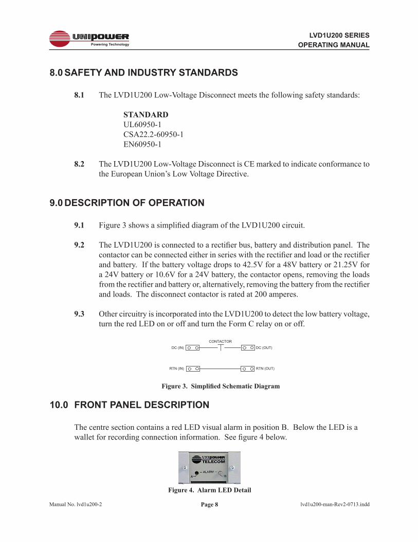
9.1 Figure 3 shows a simplified diagram of the LVD1U200 circuit.
9.2 The LVD1U200 is connected to a rectifier bus, battery and distribution panel. The contactor can be connected either in series with the rectifier and load or the rectifier and battery. If the battery voltage drops to 42.5V for a 48V battery or 21.25V for a 24V battery or 10.6V for a 24V battery, the contactor opens, removing the loads from the rectifier and battery or, alternatively, removing the battery from the rectifier and loads. The disconnect contactor is rated at 200 amperes.
9.3 Other circuitry is incorporated into the LVD1U200 to detect the low battery voltage, turn the red LED on or off and turn the Form C relay on or off.
DC (IN)
CONTACTOR
RTN (IN) RTN (OUT)
DC (OUT)
DC (IN) CONTACTORSYSTEMRECTIFIER / LOAD BUS
To RB+/RB-(Fig 5.)
SYSTEMRETURN BUS RTN (IN) RTN (OUT)
DC (OUT)+/-V(BAT)
LVD1U200
RTN(BAT)
DC (IN) CONTACTORSYSTEMRECTIFIER / LOAD BUS
To RB+/RB-(Fig 5.)
SYSTEMRETURN BUS RTN (IN) RTN (OUT)
DC (OUT)+/-V(BAT)
LVD1U200
RTN(BAT)
Figure 3. Simplified Schematic Diagram
10.0 FRONT PANEL DESCRIPTION
The centre section contains a red LED visual alarm in position B. Below the LED is a wallet for recording connection information. See figure 4 below.
Figure 4. Alarm LED Detail

Page 9
LVD1U200 SERIESOPERATING MANUAL
Manual No. lvd1u200-2 lvd1u200-man-Rev2-0713.indd
11.0 REAR PANEL DESCRIPTION
11.1 See Figure 5. The DC power inputs to the distribution panels are made by means of crimp type lugs or direct connection to ¼-20 studs to two copper bus bars on side A and side B. The upper bus bar is the battery connection (whether + or -) and the lower bus bar is the return (whether + or -).
11.2 Figure 5a below shows battery disconnect operation using the RTN bus as a connection path from the RTN(BAT) to systems return.
DC (IN)
CONTACTOR
RTN (IN) RTN (OUT)
DC (OUT)
DC (IN) CONTACTORSYSTEMRECTIFIER / LOAD BUS
To RB+/RB-(Fig 5.)
SYSTEMRETURN BUS RTN (IN) RTN (OUT)
DC (OUT)+/-V(BAT)
LVD1U200
RTN(BAT)
DC (IN) CONTACTORSYSTEMRECTIFIER / LOAD BUS
To RB+/RB-(Fig 5.)
SYSTEMRETURN BUS RTN (IN) RTN (OUT)
DC (OUT)+/-V(BAT)
LVD1U200
RTN(BAT)
Figure 5a. Connection Schematic – Battery RTN connected to RTN(OUT)
11.3 Figure 5b shows battery disconnect operation with RTN(BAT) connected directly to system return.
DC (IN)
CONTACTOR
RTN (IN) RTN (OUT)
DC (OUT)
DC (IN) CONTACTORSYSTEMRECTIFIER / LOAD BUS
To RB+/RB-(Fig 5.)
SYSTEMRETURN BUS RTN (IN) RTN (OUT)
DC (OUT)+/-V(BAT)
LVD1U200
RTN(BAT)
DC (IN) CONTACTORSYSTEMRECTIFIER / LOAD BUS
To RB+/RB-(Fig 5.)
SYSTEMRETURN BUS RTN (IN) RTN (OUT)
DC (OUT)+/-V(BAT)
LVD1U200
RTN(BAT)
Figure 5b. Connection Schematic – Battery RTN connected to System RTN
11.4 For load disconnect the LVD can be transferred to the load circuit in a similar way to that shown in Figure 5.

Page 10
LVD1U200 SERIESOPERATING MANUAL
Manual No. lvd1u200-2 lvd1u200-man-Rev2-0713.indd
11.5 The above connections to the LVD1U200 are made by means of crimp-type lugs or direct connection to ¼-20 studs on the copper bus bars on side A or B. Spacings are detailed in figure 6 below.
0.625”
1.48”
0.5”
0.34”
0.375”
0.65”
Figure 6. Input Bus Bar Detail
11.6 A list of compatible crimp-type lugs is shown in the following table for AWG wire sizes from no. 1 to 8 and one-hole or two-hole lugs. These lugs can be ordered directly from the manufacturer, Panduit Corp., using the part numbers shown in the table. A standard kit of four two-hole crimp type lugs for no. 6 AWG copper wire is available from UNIPOWER, order kit no. 775-1434-0000.
Recommended torque on the nuts securing the lugs is 40 inch-pounds.
WIREAWG
.25DIA.HOLES
PANDUIT CORP.PART NUMBER
UNIPOWERPART NUMBER
8 12
LCA8-14-LLCD8-14A-L
625-1665-0010625-1665-0110
6 12
LCA6-14-LLCD6-14A-L
625-1665-0020625-1665-0120
4 12
LCA4-14-LLCD4-14A-L
625-1665-0030625-1665-0130
2 12
LCA2-14-QLCD2-14A-Q
625-1665-0040625-1665-0140
1 12
LCA1-14-ELCD1-14A-E
625-1665-0050625-1665-0150

Page 11
LVD1U200 SERIESOPERATING MANUAL
Manual No. lvd1u200-2 lvd1u200-man-Rev2-0713.indd
12.0 FORM C RELAY CONTACTS
12.1 The centre of the back panel has connections to the Form C relay contacts for connection to external audible or visual alarm circuits; see Figure 7 below.
1 2 3 4 5 6
7 8 9 10 11 12SIDE B
NO
C NC
RB
-
RB
-
RB
+
RELAYCONTACTS
OUTPUTS
NC
C
NO
LVDALARMRELAY
RECTIFIERBUS
INPUT
.045” SQ. WIRE-WRAPPOSTS
Figure 7. Wire-Wrap Terminal Connections
12.2 The LVD1U200 has one set of Form C relay contacts and three rectifier bus input connections. Only the bottom row of contacts (as shown and marked B) are used. There are six contacts, three for Form C and three rectifier bus inputs. Pins 7, 8 and 9 are N.O., C, and N.C. connections respectively; pins 10 and 11 are -Ve rectifier bus and pin 12 is +Ve rectifier bus.
12.3 The Form C relay contacts indicate an alarm condition, i.e., the LVD contactor is open. “Normally Closed” (N.C.) and “Normally Open” (N.O.) are defined with the LVD1U200 powered; under this “normal” condition the relay is energized. The table below summarizes these connections.
ALARM PIN CONNECTIONS
PIN FUNCTION PIN FUNCTION
1 No Connection 7 Relay Contact - NO
2 No Connection 8 Relay Contact - Common
3 No Connection 9 Relay Contact - NC
4 No Connection 10 Alarm Board Power In -Ve
5 No Connection 11 Alarm Board Power In -Ve
6 No Connection 12 Alarm Board Power In +Ve
12.4 The above connections are .045 inch square wire-wrap terminals which can accept wire sizes from no. 18 to 22 AWG. The Form C relay contact ratings are 0.6A at 125VAC or 2A at 30VDC.
12.5 Just below the 12 wire-wrap terminals is the chassis ground terminal. This terminal is a no. 8-32 stud with nut.

Page 12
LVD1U200 SERIESOPERATING MANUAL
Manual No. lvd1u200-2 lvd1u200-man-Rev2-0713.indd
13.0 INSTALLATION
13.1 Mounting. This low-voltage disconnect can be mounted in either 19-inch or 23-inch racks by using the appropriate brackets. Mount it from the front of the rack using the correct offsets to align with existing rack-mounted equipment. The bracket offsets are every quarter inch from front to back.
13.1 Connections. Power connections should be made with one- or two-terminal crimp-type lugs using copper wire size from no.1 to 8 AWG, depending on current and wire length. See Section 11. The Form C relay contact and rectifier bus connections are made to the wire-wrap terminals; see Section 12. The chassis ground connection is made to the no. 8-32 stud; see Section 12. This safety ground connection should be made before operating the panel.
13.2 Checking Connections. Carefully check the polarity and correctness of all connections to the LVD1U200 before operating the unit. Reverse connections will not harm the LVD1U. Check to make sure that the chassis safety ground connection is made. Make sure that all connections are clean and firm to minimize contact resistance.

Page 13
LVD1U200 SERIESOPERATING MANUAL
Manual No. lvd1u200-2 lvd1u200-man-Rev2-0713.indd
14.0 SETUP AND TESTING
14.1 It is not necessary to have the LVD1U200 mounted in a rack for initial testing. This can be done on a bench. It is not necessary to have loads connected to the LVD1U200 for these tests.
14.2 Set an unconnected bench-type DC power supply with digital voltage display to 48VDC if a 48V LVD1U200 is being set up or to 24VDC if a 24V unit is being set up or to 12VDC if a 12V unit is being set up. Turn the power supply off.
14.3 Connect the power supply to Row B of the wire-wrap pins on the back of the LVD. Connect the minus output to pin 10 or 11 and the plus output to pin 12. It is not necessary to make connection to the Battery, Rectifier or Load bus bars terminals for this test.
14.4 Turn the power supply on. The LED for side B should be off. Reduce the power supply output voltage slowly while observing the output voltage. At approximately 42.5V for the 48V version or 21.25V for the 24V version or 10.6V for the 12V version the red LED should turn on. With an ohmmeter, measure the resistance between wire-wrap terminals 8 (C) and 7 (N.O.). It should measure a short.
14.5 Increase the power supply output voltage slowly while observing the voltage. At approximately 49.0V for the 48V version or 24.5V for the 24V version or 12.25V for the 12V version the red LED should turn off. With an ohmmeter, measure the resistance between wire-wrap terminals 9 (N.C.) and 8 (C). It should measure a short.
14.6 Turn off the power supply and disconnect the LVD1U200. It is now ready for operation in the telecom system.
Please note that there are no user serviceable parts inside either the modules or the shelves and that opening either will void the warranty.
If you are unable to resolve any problem call your nearest UNIPOWER sales office for support:
US +1 954 346 2442 UK +44 (0)1903 768200

Page 14
LVD1U200 SERIESOPERATING MANUAL
Manual No. lvd1u200-2 lvd1u200-man-Rev2-0713.indd
This document is believed to be correct at time of publication and UNIPOWER LLC accepts no responsibility for consequences from printing errors or inaccuracies. Specifications are subject to change without notice.
Appendix - REVISION HISTORY
Rev. # Date Detail Page
1 07/2012 WEB release
2 07/2013 General update various