Operating manual for message text display - Kuebler operating manual . We do not assume any...
61
Operating manual for message text display reporter 690 1.95.3 (ed 4.95)
Transcript of Operating manual for message text display - Kuebler operating manual . We do not assume any...

Operating manual for message text display
reporter 690
1.95.3 (ed 4.95)

Dear customer,
the manufacturer is not liable for any damage caused as a result of non-observance of theoperating manual . We do not assume any liability for resultant damages.
Please read the operating manual carefully before operating the reporter 690.
! Attention: Read this!
iOperating manual reporter 690
Table of Contents
Table of Contents
1. Safety notes 11.1 Use according to intended purpose ............................................................................ 1-11.2 Technical condition ..................................................................................................... 1-11.3 General safety regulations .......................................................................................... 1-21.4 Cleaning ...................................................................................................................... 1-2
2. Getting acquainted with reporter 690 22.1 Features ...................................................................................................................... 2-12.2 Operating elements and connections ......................................................................... 2-12.3 Function overview ....................................................................................................... 2-3
3. Connection of the reporter 690 33.1 Connection of the power supply ................................................................................. 3-13.2 Serial interface connection ......................................................................................... 3-23.3 Parallel message and control inputs ........................................................................... 3-33.4 Assign message output .............................................................................................. 3-4
4. REPORT Programming software 44.1 System environment ................................................................................................... 4-14.2 Installation and calling ................................................................................................ 4-14.3 REPORT Operating instructions ................................................................................. 4-24.4 REPORT Operation .................................................................................................... 4-34.5 "On line" help ............................................................................................................. 4-44.6 Quit the REPORT ....................................................................................................... 4-4
5. How to program the reporter 690 55.1 Set the interface parameters [Communication] .................................................... 5-15.1.1 Select serial port [Number PC interface] .................................................................... 5-15.1.2 Set the baud rate [Baud rate PC interface] ................................................................. 5-15.1.3 Select the communications type [Type Interface] ...................................................... 5-15.1.4 Indicate the serial port status [State interface] ........................................................... 5-25.2 Program the set-up [Set-up display] ...................................................................... 5-25.2.1 Manage the setup data ............................................................................................... 5-25.2.2 With or without option package? [Option Paket] ........................................................ 5-35.2.3 Edit setup data [Edit] ................................................................................................... 5-3
Set the baud rate [Baud rate display] ......................................................................... 5-3Set the device address [Adress (RS422/RS485)] ...................................................... 5-3Set operating mode for message text calling [Message mode] ................................. 5-4Determine the signal allocation for parallel interface [Binary/BCD] ........................... 5-5Parallel data transmission with and without strobe [Strobe input] .............................. 5-5Set delay time for static data acceptance [Input delay] .............................................. 5-6Set acknowledgement for parallel data transmission [Output] ................................... 5-6Release/lock operating key MPI [Key] ........................................................................ 5-7Acoustic acknowledgement signal on/off [Buzzer] ..................................................... 5-7Select the language [Character set] ........................................................................... 5-7Set blink rate of message texts [Blink rate] ................................................................ 5-7
ii Operating manual reporter 690
Table of Contents
Setting the cycle time for the moving screen [Cycle time] .......................................... 5-7How to program the power-on message [power-on message] .................................. 5-7
5.3 Programming of message texts [Textfile] .............................................................. 5-85.3.1 Management of messages ......................................................................................... 5-85.3.2 Message text editor [Edit] ........................................................................................... 5-9
To operate the window ............................................................................................... 5-9Message text addresses ........................................................................................... 5-10Enter message texts ................................................................................................. 5-10Allocate variable numbers ........................................................................................ 5-11Program attributes .................................................................................................... 5-12Enter default message .............................................................................................. 5-13
5.4 Additional and special functions [Commands] ................................................... 5-145.4.1 Call messages .......................................................................................................... 5-145.4.2 Programm variable data [Variable value] ................................................................. 5-145.4.3 Monitor mode [Monitor] ............................................................................................. 5-145.4.4 Optional diagnostic memory [Diagnostic memory] ................................................... 5-155.4.5 Set time and date (optional) [Time and date] ........................................................... 5-155.4.6 Activate special functions [Special funktions] ........................................................... 5-16
Delete stack memory ................................................................................................ 5-16Moving screen .......................................................................................................... 5-16Display parameters ................................................................................................... 5-16Forward output of text ............................................................................................... 5-16Backward output of text ............................................................................................ 5-16Display test ............................................................................................................... 5-16End of special functions ............................................................................................ 5-16
5.5 Terminal program ................................................................................................... 5-17
6. How to operate the reporter 690 66.1 Control via the parallel interface ............................................................................. 6-16.1.1 Call-in message texts ................................................................................................. 6-26.1.2 Transmit variable values ............................................................................................. 6-46.1.3 Activate special functions ........................................................................................... 6-56.2 Control via the serial interface ................................................................................ 6-66.2.1 Auto-Baud Recognition ............................................................................................... 6-66.2.2 Data transmission protocol ......................................................................................... 6-76.2.3 Data-acknowledgement .............................................................................................. 6-86.2.4 Calling message numbers .......................................................................................... 6-96.2.5 Indicate message texts as moving screen ................................................................. 6-96.2.6 Transmit variable values ........................................................................................... 6-106.2.7 Activate special functions ......................................................................................... 6-10
Control of the monitor mode: .................................................................................... 6-10
Appendix A AA.1 Activation via interface RS 422/485 ........................................................................... A-1A.2 Overview of the control codes ................................................................................... A-2A.3 Handshake serial interface ........................................................................................ A-3A.4 Mechanical dimensions ............................................................................................. A-4A.5 Pin configuration ........................................................................................................ A-5A.6 Technical Data ........................................................................................................... A-6A.7 Order key ................................................................................................................... A-7A.7.1 Delivery specification ................................................................................................. A-7

1-1Operating manual reporter 690
1. Safety notes
1.
1.2 Technical condition
If a supposed unsafe operation is possible, switch off the reporter 690 and secure it againstunintended switch-on. This must be supposed especially in the following cases:
� the display shows visible damages� the display does not work or works in an uncontrolled manner� in case of a prolonged storage under inadmissible conditions� after mishandling during transport
1. Safety notes
This reporter 690 left the factory in a safe and reliable condition. To maintain thiscondition and to guarantee troublefree operation, the safety notes and warningsmust be absolutely observed. They are marked in the operating manual and onthe device with this sign:
The reporter 690 must only be used indoors as a built-in display. Insure that thedisplay is installed correctly and that the operating limits are followed (see technicaldata).
Do not operate the reporter 690 outdoors or in areas subject to explosion hazardsdue to inflammable gases, vapors or dusts.
The reporter 690 is not suitable for operation at installations with fast temperaturevariations and/or a high humidity, as there is a risk of condensation of water in thedevice.
If the alarm output of the reporter 690 is used for machine control or for technicalprocesses which comprise a danger to properties and persons due to troubles orfaulty operation of the reporter 690, relevant safety precautions must be taken.
1.1 Use according to intended purpose
The reporter 690 was designed and manufactured according to the VDE standards andEN 61 010 part 1. Use this display only
� according to its intended use� in technically correct conditions� in accordance with the operating instructions and the general safety notes
1-2 Operating manual reporter 690
1.
1. Safety notes
1.3 General safety regulations
The connection, maintenance or repair work at the reporter 690 must be carried out only by atrained person who is familiar with the risks connected with this work and the relevant regulations,unless this work is performed by the manufacturer or an authorized person.
Please ensure that the persons entrusted with the operation, maintenance and installation of thereporter 690 have access to this operating manual.
1.4 Cleaning
Use a soft cloth moistened with water to clean the front side of the device, if necessary.
2-1������������� �����������
2.
2. Getting acquainted with reporter 690
2. Getting acquainted with reporter 690
2.1 Features
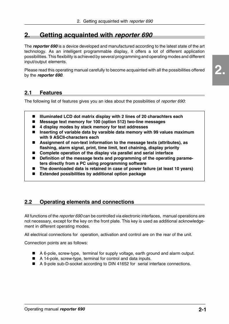
� Illuminated LCD dot matrix display with 2 lines of 20 charachters each� Message text memory for 100 (option 512) two-line messages� 4 display modes by stack memory for text addresses� Inserting of variable data by varaible data memory with 99 values maximum
with 9 ASCII-characters each� Assignment of non-text information to the message texts (attributes), as
flashing, alarm signal, print, time limit, text chaining, display priority� Complete operation of the display via parallel and serial interface� Definition of the message texts and programming of the operating parame-
ters directly from a PC using programming software� The downloaded data is retained in case of power failure (at least 10 years)� Extended possibilities by additional option package
2.2 Operating elements and connections
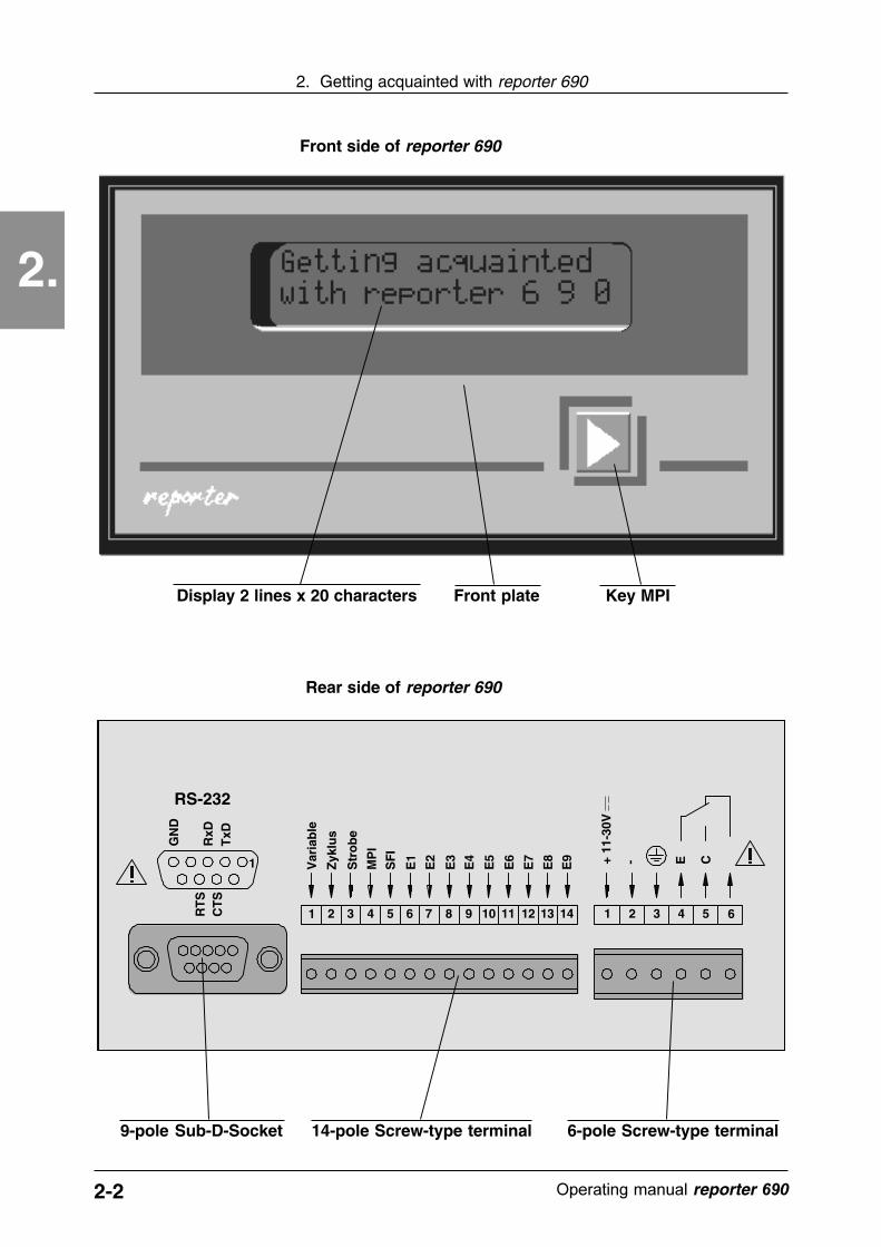
All functions of the reporter 690 can be controlled via electronic interfaces, manual operations arenot necessary, except for the key on the front plate. This key is used as additional acknowledge-ment in different operating modes.
All electrical connections for operation, activation and control are on the rear of the unit.
Connection points are as follows:
� A 6-pole, screw-type, terminal for supply voltage, earth ground and alarm output.� A 14-pole, screw-type, terminal for control and data inputs.� A 9-pole sub-D-socket according to DIN 41652 for serial interface connections.
The reporter 690 is a device developed and manufactured according to the latest state of the arttechnology. As an intelligent programmable display, it offers a lot of different applicationpossibilities. This flexibility is achieved by several programming and operating modes and differentinput/output elements.
Please read this operating manual carefully to become acquainted with all the possibilities offeredby the reporter 690.
The following list of features gives you an idea about the possibilities of reporter 690:
2-2 ������������� reporter ��
2.
2. Getting acquainted with reporter 690
Front side of reporter 690
Display 2 lines x 20 characters Key MPIFront plate
Zyk
lus
Str
ob
e
SF
I
MP
I
E1
E2
E3
E4
E5
E6
E7
E8
E9 +
11-3
0V
- E C
1 1312111098765432 14 1 2 3 4 5 6
Var
iab
le
1
RS-232
Rear side of reporter 690
6-pole Screw-type terminal9-pole Sub-D-Socket 14-pole Screw-type terminal
TxD
RxD
GN
D
RT
SC
TS
2-3������������� �����������
2.
2. Getting acquainted with reporter 690
2.3 Function overview
In this chapter you become acquainted with the design and the basic functions of the reporter 690.It gives you a brief overview. A more detailed description can be found in the correspondingchapters.
Memory for the message texts
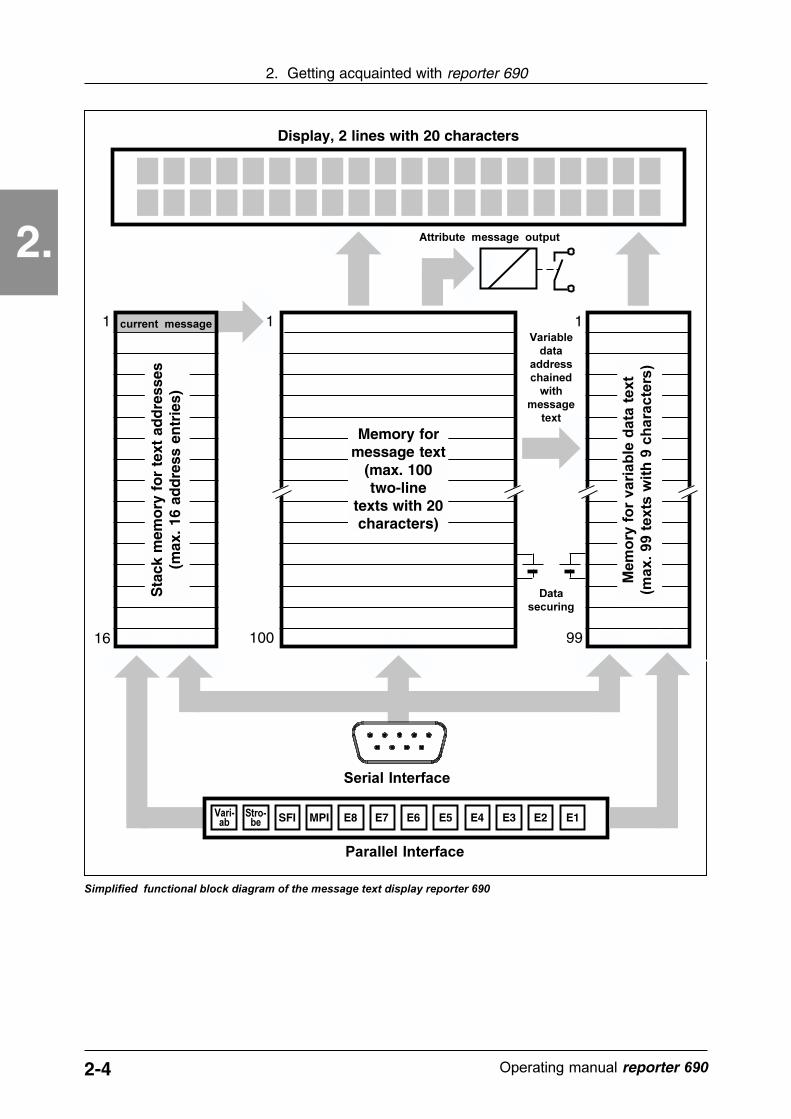
Texts, to be indicated on the display, must already be stored in the reporter 690 memory. Thismeans only the message number is transmitted via one of the interfaces and not the text itself. Atwo-line by 20 character messages each can be saved per address. Up to 100 (option 512)message numbers may be assigned text. Message text is generated directly at the PC with theREPORT programming software (included in delivery) and then transmitted to reporter 690memory via the serial interface. Message data is retained up to 10 years in memory in the eventof power loss. The messages, of course, can be changed at any time.
Stack memory for text addresses
If a message number is transmitted to the reporter 690 via one of the interfaces, the numberis sent to stack memory. This stack memory has 16 storage locations and each of these locationscan take one message number. Stack memory location no. 1 holds the number of the activelydisplayed message.
In the most simple case an incoming message number is passed through the first stack memoryaddress and the corresponding text is immediately shown on the display. We call this aninstantaneous value display. Operating modes can also be pre-selected to enter the incoming textaddresses in the stack memory, like a shift register. Additional displays as sequence display, firstvalue display und last value display can be realized by a subsequent shifting or rotating of the stackmemory.
Memory for variable data texts
The display of data along with text is sometimes desired. The insertion of variable data can beuseful. The reporter 690 enables this by a variable data memory with the capacity of 99 texts witha maximum of 8 characters. The remarkable thing is: Placeholders with a reference to a certainaddress of variables can be inserted into each line of a fixed programmed message text. Thecontents of this address is then displayed in the message text. The variable itself can be updatedcontinuously via the interface. A typical message,as shown below, can be displayed easily:
Temperature: 20.5 °C
The explanatory text is saved in the message text memory and the temperature value will beinserted as a variable and updated as new variable data is sent to the reporter 690.
2-4 ������������� reporter ��
2.
2. Getting acquainted with reporter 690
Display, 2 lines with 20 characters
1
16
Memory formessage text
(max. 100two-line
texts with 20characters)
Sta
ck m
emo
ry f
or
text
ad
dre
sses
(max
. 16
add
ress
en
trie
s)
1
99100
1
����������������� �����
�����������
������������
������������
��������
����
E1E2E3E4E5E6E7E8MPISFI�������
����
����������������
��� ����������
������������� ������������������� ��������� �� ������������ �����
�������������
���
���
��
����
� ��
����
���
��
����
����
���
���
�
����
���
���
���
2-5������������� �����������
2.
2. Getting acquainted with reporter 690
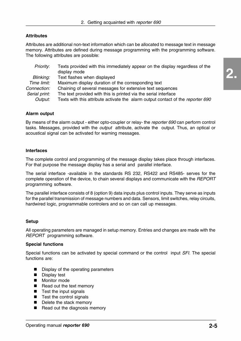
Attributes
Attributes are additional non-text information which can be allocated to message text in messagememory. Attributes are defined during message programming with the programming software.The following attributes are possible:
Priority: Texts provided with this immediately appear on the display regardless of thedisplay mode
Blinking: Text flashes when displayedTime limit: Maximum display duration of the corresponding text
Connection: Chaining of several messages for extensive text sequencesSerial print: The text provided with this is printed via the serial interface
Output: Texts with this attribute activate the alarm output contact of the reporter 690
Alarm output
By means of the alarm output - either opto-coupler or relay- the reporter 690 can perform controltasks. Messages, provided with the output attribute, activate the output. Thus, an optical oracoustical signal can be activated for warning messages.
Interfaces
The complete control and programming of the message display takes place through interfaces.For that purpose the message display has a serial and parallel interface.
The serial interface -available in the standards RS 232, RS422 and RS485- serves for thecomplete operation of the device, to chain several displays and communicate with the REPORTprogramming software.
The parallel interface consists of 8 (option 9) data inputs plus control inputs. They serve as inputsfor the parallel transmission of message numbers and data. Sensors, limit switches, relay circuits,hardwired logic, programmable controlers and so on can call up messages.
Setup
All operating parameters are managed in setup memory. Entries and changes are made with theREPORT programming software.
Special functions
Special functions can be activated by special command or the control input SFI. The specialfunctions are:
� Display of the operating parameters� Display test� Monitor mode� Read out the text memory� Test the input signals� Test the control signals� Delete the stack memory� Read out the diagnosis memory

2-6 ������������� reporter ��
2.
2. Getting acquainted with reporter 690
Option package
The reporter 690 "with option package" offers the following additional features:
� Historical memory for last 100 message numbers called� Battery-backed real-time clock� Stack memory expanded to 32 inputs� Memory expanded to 512 message numbers
REPORT Programming software
A comfortable, largely self-explaining, software enables easy programming of the reporter 690.The software requires a PC with an MS-DOS operating system to communicate with the reporter690 via a serial interface. The software is used to:
� define and manage message texts� enter defaults for variable data into the variable data memory� set operating parameters (setup)� activate and check additional and special functions

3-1������������� reporter��
3. Connection of the reporter 690
3.
3. Connection of the reporter 690This chapter covers the connections of the reporter 690, their terminal assignments and importantnotes concerning the connection.
1 Positive operating voltage connection+2 Negative operating voltage connection-3 Connection for protective earthing
Terminal Symbol Function
Terminal assignment operating voltage connection
Terminals for the power supply of the reporter 690.
Connect the supply voltage according to the printed wiring plan to terminal 1 and 2 and theprotective earthing to terminal 3. Recommended conductor cross section: 18 - 24 AWG.
Please observe:
� Apply DC voltage only� Voltage range 11 V to 30V maximum� Observe correct polarity (1=Plus, 2=Minus)� Power consumption approx. 3W
Non-observance of these points may lead to a damage of the device!
To comply with the interference immunity mentioned in the technical data� a protective earth ground must be provided.
We further recommend an interference-free supply voltage. Contactors, electroma-gnets, motors and so on should not be used with this voltage.
To observe the fire protection regulations according to EN 61 010 part 1� the supply voltage must be protected with a miniature fuse M 500 mA.
According to EN 61 010 part 1 8A/150VA (W) must not be exceeded in caseof a power failure.
Zyk
lus
Str
ob
e
SF
I
MP
I
E1
E2
E3
E4
E5
E6
E7
E8
E9 +
11-3
0V
- E C
1 1312111098765432 14 1 2 3 4 5 6
Var
iab
le
1
RS-232
TxD
RxD
GN
D
RT
SC
TS
3.1 Connection of the power supply

3-2 ������������� reporter��
3. Connection of the reporter 690
3.
2 Transmitted dataTxD3 Received dataRxD8 Request to sendRTS7 Clear to sendCTS5 GroundGND
Pin-Number Symbol FunctionSocket assignment 9-pole SUB-D-socket RS 232
3 Transmitted dataTA/RA+8 Received dataTB/RB-
Pin-Number Symbol FunctionSocket assignment 9-pole SUB-D-pin RS485
2 Transmitted dataTA+6 Transmitted dataTB-4 Received dataRA+8 Received dataRB-
Pin-Number Symbol FunctionSocket assignment 9-pole SUB-D-pin RS422
Attention: This connection is intended only standard data transmission in accordancewith RS 232, RS 422 and RS 485. A reversed polarity or an external voltage may leadto a damage of the device! To keep the interference immunity observe to following: Usemagnetically screened cable and metalized cover. Connect screen 360° with connectorhousing. Connector housing is internally grounded.
The serial port connects the controlling unit to the reporter 690. Connect one end of the cable withthe 9-pin sub-D-socket to the reporter 690 and the other end to the controlling unit.
Zyk
lus
Str
ob
e
SF
I
MP
I
E1
E2
E3
E4
E5
E6
E7
E8
E9 +
11-3
0V
- E C
1 1312111098765432 14 1 2 3 4 5 6
Var
iab
le1
RS-232T
xDR
xD
GN
D
RT
SC
TS
Connecting socket for the serial interface of the reporter 690.
3.2 Serial interface connection
3-3������������� reporter��
3. Connection of the reporter 690
3.Z
yklu
s
Str
ob
e
SF
I
MP
I
E1
E2
E3
E4
E5
E6
E7
E8
E9 +
11-3
0V
- E C
1 1312111098765432 14 1 2 3 4 5 6
Var
iab
le1
RS-232
TxD
RxD
GN
D
RT
SC
TS
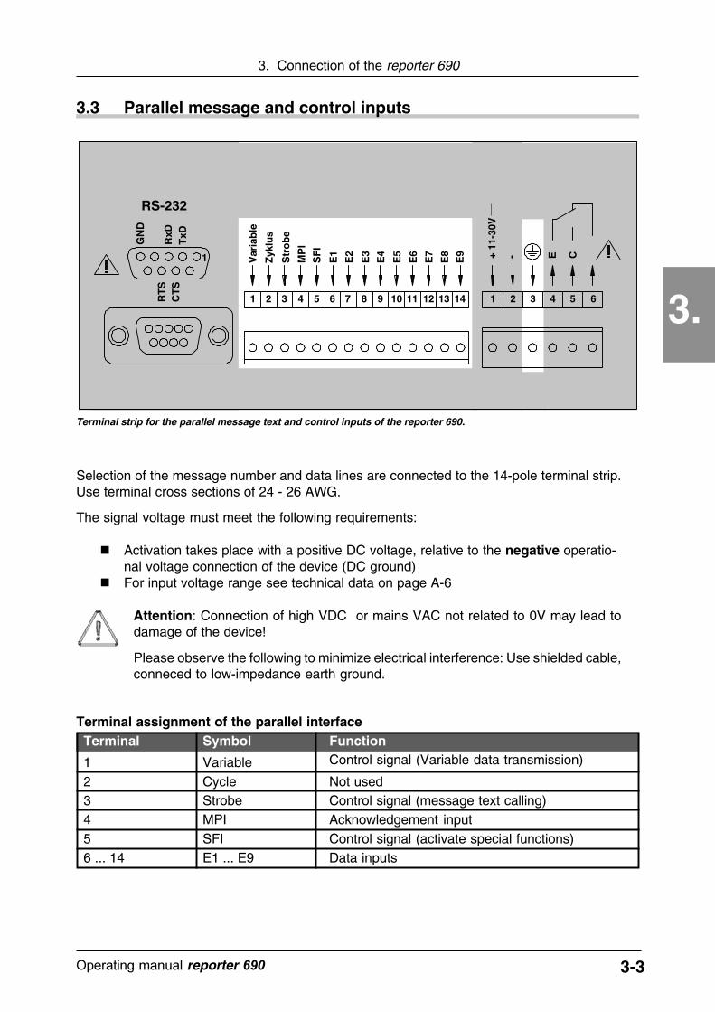
Selection of the message number and data lines are connected to the 14-pole terminal strip.Use terminal cross sections of 24 - 26 AWG.
The signal voltage must meet the following requirements:
� Activation takes place with a positive DC voltage, relative to the negative operatio-nal voltage connection of the device (DC ground)
� For input voltage range see technical data on page A-6
Attention: Connection of high VDC or mains VAC not related to 0V may lead todamage of the device!
Please observe the following to minimize electrical interference: Use shielded cable,conneced to low-impedance earth ground.
1 Control signal (Variable data transmission)Variable2 Not usedCycle3 Control signal (message text calling)Strobe4 Acknowledgement inputMPI
Terminal Symbol Function
5 Control signal (activate special functions)SFI6 ... 14 Data inputsE1 ... E9
Terminal assignment of the parallel interface
Terminal strip for the parallel message text and control inputs of the reporter 690.
3.3 Parallel message and control inputs

3-4 ������������� reporter��
3. Connection of the reporter 690
3.Z
yklu
s
Str
ob
e
SF
I
MP
I
E1
E2
E3
E4
E5
E6
E7
E8
E9 +
11-3
0V
- E C
1 1312111098765432 14 1 2 3 4 5 6
Var
iab
le1
RS-232T
xDR
xD
GN
D
RT
SC
TS
Terminals for the message output of reporter 690.
3.4 Assign message output
The connections 4,5,6 of the 6-pole terminal strip are the message output of reporter 690.
Please observe the following:
� According to the type it concerns a relay two-way contact or an opto-coupler output� Relay limits: Umax = 250VAC/30VDC, Imax =3A� Opto-coupler limits: Umax = 30VDC, Imax = 15 mA
Attention:
� Exceeding of these limits may damage the device!� The electronic output is not short-circuit proof!� The relay contact must not be used as an emergency stop according to VDE!� The user must take precautions so that a switching load of 8A / 150 VA (W) is not
exceeded (EN 61 010 part 1).� Connect only with wire end sleeves with insulating covers to prevent accidental
against contact.
4 5 6 4 5 6
Relay change-over contact Opto-coupler output
Centre contact
Emitter Collector
Pin configuration of the message output for relay and opto-coupler type.
Break contact
Makecontact

4-1Operating manual reporter 690
4. Programming software REPORT
4.
4. REPORT Programming software
4.1 System environment
Your PC should meet the following requirements:
4.2 Installation and calling
Disk format: 3 1/2 in / 720 KByte
System environment: PC compatible to MS-DOSDOS version 5.0 or later540KB free main storageRS232 Serial interfaceAny screen
Further recommendations: Fixed diskMouseColor-screenPrinter
The REPORT software consists of several files. Start REPORT by typing in " report.exe" at thedos prompt. In the easiest case directly from the disk.
e.g. a:\report
or
click REPORT.EXE twice in the corresponding drive in the DOS shell.
We recommend that you install REPORT on the fixed disk, in its own directory. To do this, copyall files on the disk into the newly created directory on the fixed disk.
e. g. with the following DOS commands:c:md reportcd reportcopy a:\*.*
You may also use the installation program install.bat, which is on the disk too. It defines a directoryon your fixed disk to which all files of REPORT are copied.
This chapter contains information about the REPORT programming software. The completeprogramming of the reporter 690 is carried out with this software.

4-2 Operating manual reporter 690
4. Programming software REPORT
4.
4.3 REPORT Operating instructions
REPORT is a menu-driven program. All commands and actions are performed by activating themenu fields. The programming prompts are displayed by hierarchical menu staggering. Theprogram can be operated with the mouse (recommended) or with the keyboard.
After starting REPORT, the following picture appears: (The menu item "Setup display" with sub-menu [Reporter 690] has been already selected).
menu line menu item selected menu item background
status line menu sub-menu
Menu line:
The menu line in the upper part of the screen contains the main menu items. The 6 itemscorrespond to the 6 groups in which the complete command set of REPORT has been arranged.
Text file - Commands to manage and define message textsCommands - Additional and special functions
Setup display - Set up of operational parameters of the reporter 690Communication - Initializing of interfaces
Terminal - Interface programEnd - Quit REPORT and return to DOS
4-3Operating manual reporter 690
4. Programming software REPORT
4.
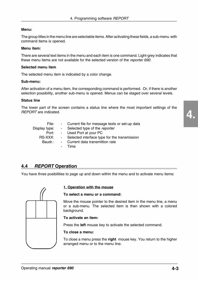
Menu:
The group titles in the menu line are selectable items. After activating these fields, a sub-menu withcommand items is opened.
Menu item:
There are several text items in the menu and each item is one command. Light-grey indicates thatthese menu items are not available for the selected version of the reporter 690.
Selected menu item
The selected menu item is indicated by a color change.
Sub-menu:
After activation of a menu item, the corresponding command is performed. Or, if there is anotherselection possibility, another sub-menu is opened. Menus can be staged over several levels.
Status line
The lower part of the screen contains a status line where the most important settings of theREPORT are indicated.
File: - Current file for message texts or set-up dataDisplay type: - Selected type of the reporter
Port: - Used Port at your PCRS-XXX: - Selected interface type for the transmission
Baudr.: - Current data transmittion rate- Time
4.4 REPORT Operation
You have three posibilities to page up and down within the menu and to activate menu items:
1. Operation with the mouse
To select a menu or a command:
Move the mouse pointer to the desired item in the menu line, a menuor a sub-menu. The selected item is then shown with a coloredbackground.
To activate an item:
Press the left mouse key to activate the selected command.
To close a menu:
To close a menu press the right mouse key. You return to the higherarranged menu or to the menu line.
4-4 Operating manual reporter 690
4. Programming software REPORT
4.
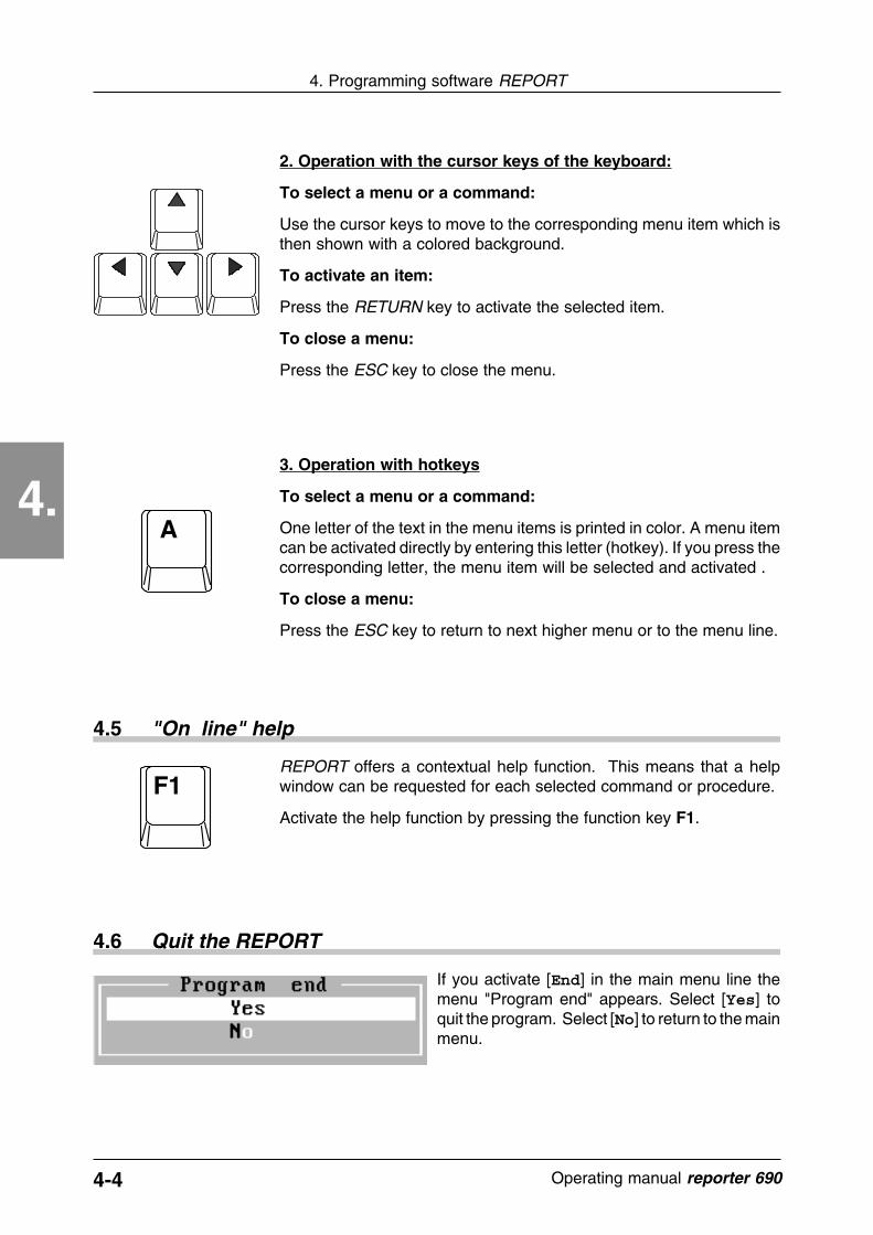
2. Operation with the cursor keys of the keyboard:
To select a menu or a command:
Use the cursor keys to move to the corresponding menu item which isthen shown with a colored background.
To activate an item:
Press the RETURN key to activate the selected item.
To close a menu:
Press the ESC key to close the menu.
3. Operation with hotkeys
To select a menu or a command:
One letter of the text in the menu items is printed in color. A menu itemcan be activated directly by entering this letter (hotkey). If you press thecorresponding letter, the menu item will be selected and activated .
To close a menu:
Press the ESC key to return to next higher menu or to the menu line.
A
4.5 "On line" help
F1REPORT offers a contextual help function. This means that a helpwindow can be requested for each selected command or procedure.
Activate the help function by pressing the function key F1.
4.6 Quit the REPORT
If you activate [End] in the main menu line themenu "Program end" appears. Select [Yes] toquit the program. Select [No] to return to the mainmenu.
5-1������������� �����������
5. How to program the reporter 690
5.
5. How to program the reporter 690
In this chapter you will learn how to program the display reporter 690 by means of the REPORTprogramming software. "Programming" means:
� determining the transmission parameters between PC and display� setting the operating parameters (Setup) of the reporter 690� generating message texts� additional functions and settings
The order of this lists corresponds with the order in which the programming should take place.Make sure you have a correct serial connection between reporter 690 and the PC.
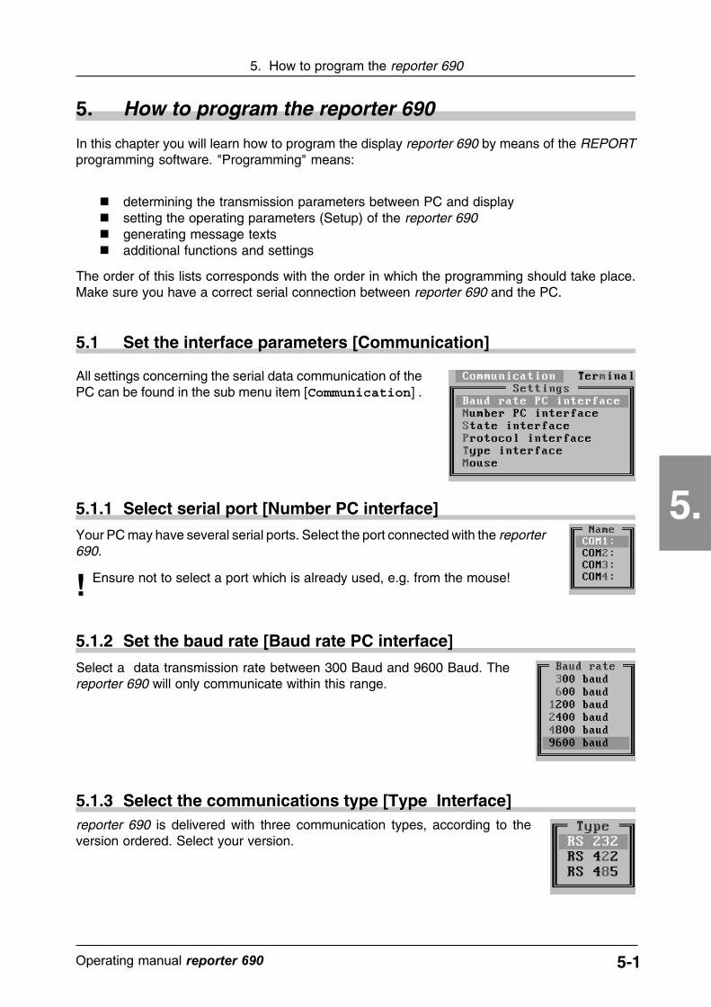
5.1 Set the interface parameters [Communication]
All settings concerning the serial data communication of thePC can be found in the sub menu item [Communication] .
Your PC may have several serial ports. Select the port connected with the reporter690.
! Ensure not to select a port which is already used, e.g. from the mouse!
5.1.2 Set the baud rate [Baud rate PC interface]
5.1.1 Select serial port [Number PC interface]
Select a data transmission rate between 300 Baud and 9600 Baud. Thereporter 690 will only communicate within this range.
reporter 690 is delivered with three communication types, according to theversion ordered. Select your version.
5.1.3 Select the communications type [Type Interface]
5-2 ������������� reporter ��
5. How to program the reporter 690
5.
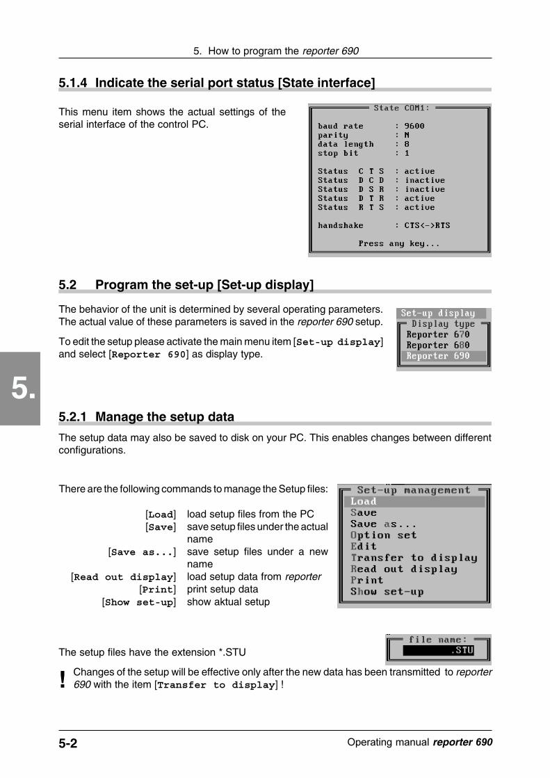
This menu item shows the actual settings of theserial interface of the control PC.
5.1.4 Indicate the serial port status [State interface]
5.2 Program the set-up [Set-up display]
The behavior of the unit is determined by several operating parameters.The actual value of these parameters is saved in the reporter 690 setup.
To edit the setup please activate the main menu item [Set-up display]and select [Reporter 690] as display type.
The setup data may also be saved to disk on your PC. This enables changes between differentconfigurations.
5.2.1 Manage the setup data
There are the following commands to manage the Setup files:
[Load] load setup files from the PC[Save] save setup files under the actual
name[Save as...] save setup files under a new
name[Read out display] load setup data from reporter
[Print] print setup data[Show set-up] show aktual setup
Changes of the setup will be effective only after the new data has been transmitted to reporter690 with the item [Transfer to display] !!
The setup files have the extension *.STU

5-3������������� �����������
5. How to program the reporter 690
5.
5.2.2 With or without option package? [Option set]
Select whether the reporter 690 to be programmed correspondsto the version "with" or "without option package".
The option package contains:
� Extended memory to 512 message texts� Extended stack memory to 32 items� Battery-backed real-time clock� Diagnostic memory
5.2.3 Edit setup data [Edit]
Select the item [Edit] in the menu "Set-up manage-ment" to edit the different setup parameters. The sub-menu "Set-up parameter" appears for the selectionof the individual parameters.
Set the baud rate [Baud rate display]
Set the reporter 690 serial interface baud rate here. Select a transmission ratewhich corresponds with the control PC.
Set the device address [Adress (RS422/RS485)]
Enter the address in hexadecimal values (0..F) !
If the display is a type with RS 422 or RS 485 communications, thereporter 690 requires a device address that corresponds to theprotocol procedures used. You may enter a device addressbetween 0..15.
!
5-4 ������������� reporter ��
5. How to program the reporter 690
5.
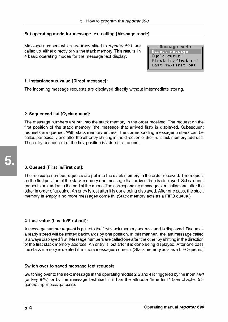
Message numbers which are transmitted to reporter 690 arecalled up either directly or via the stack memory. This results in4 basic operating modes for the message text display.
1. Instantaneous value [Direct message]:
The incoming message requests are displayed directly without imtermediate storing.
2. Sequenced list [Cycle queue]:
The message numbers are put into the stack memory in the order received. The request on thefirst position of the stack memory (the message that arrived first) is displayed. Subsequentrequests are queued. With stack memory entries, the corresponding messagenumbers can becalled periodically one after the other by shifting in the direction of the first stack memory address.The entry pushed out of the first position is added to the end.
3. Queued [First in/First out]:
The message number requests are put into the stack memory in the order received. The requeston the first position of the stack memory (the message that arrived first) is displayed. Subsequentrequests are added to the end of the queue.The corresponding messages are called one after theother in order of queuing. An entry is lost after it is done being displayed. After one pass, the stackmemory is empty if no more messages come in. (Stack memory acts as a FIFO queue.)
4. Last value [Last in/First out]:
A message number request is put into the first stack memory address and is displayed. Requestsalready stored will be shifted backwards by one position. In this manner, the last message calledis always displayed first. Message numbers are called one after the other by shifting in the directionof the first stack memory address. An entry is lost after it is done being displayed. After one passthe stack memory is deleted if no more messages come in. (Stack memory acts as a LIFO queue.)
Switch over to saved message text requests
Switching over to the next message in the operating modes 2,3 and 4 is triggered by the input MPI(or key MPI) or by the message text itself if it has the attribute "time limit" (see chapter 5.3generating message texts).
Set operating mode for message text calling [Message mode]
5-5������������� �����������
5. How to program the reporter 690
5.
Display,Message text
memory
Display,Message text
memory
Display,Message text
memory
Display,Message text
memoryS
tack
mem
ory
Sta
ck m
emo
ry
Sta
ck m
emo
ry
Sta
ck m
emo
ry
Instaneousvalue message
Sequencemessage
First valuemessage
Last valuemessage
Call Call Call Call1,2,3,4 1,2,3,4 1,2,3,4 1,2,3,4
2
1
3
4
2
1
3
4
1
2
3
4
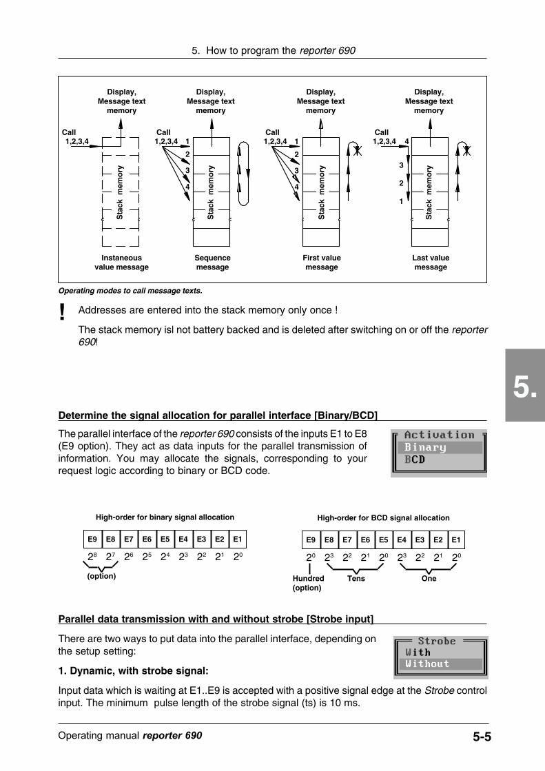
Operating modes to call message texts.
Parallel data transmission with and without strobe [Strobe input]
There are two ways to put data into the parallel interface, depending onthe setup setting:
1. Dynamic, with strobe signal:
Input data which is waiting at E1..E9 is accepted with a positive signal edge at the Strobe controlinput. The minimum pulse length of the strobe signal (ts) is 10 ms.
Addresses are entered into the stack memory only once !
The stack memory isl not battery backed and is deleted after switching on or off the reporter690!
!
Determine the signal allocation for parallel interface [Binary/BCD]
The parallel interface of the reporter 690 consists of the inputs E1 to E8(E9 option). They act as data inputs for the parallel transmission ofinformation. You may allocate the signals, corresponding to yourrequest logic according to binary or BCD code.
E9 E8 E7 E6 E5 E4 E3 E2 E1
20 23 22 21 20 23 22 21 20
High-order for BCD signal allocation
E9 E8 E7 E6 E5 E4 E3 E2 E1
28 27 26 25 24 23 22 21 20
High-order for binary signal allocation
Hundred(option)
Tens One(option)
5-6 ������������� reporter ��
5. How to program the reporter 690
5.
2. Static, without strobe signal:
When the reporter 690 recognizes a data change at the inputs E1... E9, a delay time (td) is startedinternally. After expiration of td, the data, waiting at this moment, is accepted. If a new data changeis recognized before expiration of td, the delay time is restarted.
The delay time td can be set in the setup, see next point.
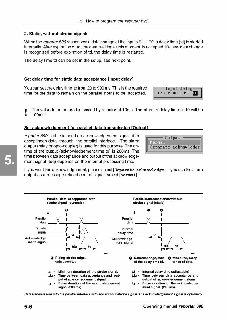
1
Paralleldata
Strobesignal
Acknowledge-ment signal
1 Rising strobe edge,data accepted.
ts
tdq tq
td
tdq tq
1 2
Internaldelay time
Acknowledge-ment signal
1 Data exchange, startof the delay time td.
td expired, accep-tance of data.
2
td - Internal delay time (adjustable)tdq - Time between data acceptance and
output of acknowledgement signal.tq - Pulse duration of the acknowledge-
ment signal (200 ms).
ts - Minimum duration of the strobe signal.tdq - Time between data acceptance and out-
put of acknowledgement signal .tq - Pulse duration of the acknowledgement
signal (200 ms).
Data transmission into the parallel interface with and without strobe signal. The acknowledgement signal is optionally.
Set acknowledgement for parallel data transmission [Output]
reporter 690 is able to send an acknowledgement signal afteracceptingan data through the parallel interface. The alarmoutput (relay or opto-coupler) is used for this purpose. The on-time of the output (acknowledgement time tq) is 200ms. Thetime between data acceptance and output of the acknowledge-ment signal (tdq) depends on the internal processing time.
If you want this acknowledgement, please select [Separate acknowledge]. If you use the alarmoutput as a message related control signal, select [Normal].
Set delay time for static data acceptance [Input delay]
You can set the delay time td from 20 to 990 ms. This is the requiredtime for the data to remain on the parallel inputs to be accepted.
The value to be entered is scaled by a factor of 10ms. Therefore, a delay time of 10 will be100ms!!
Parallel data accepptance withstrobe signal (dynamic)
Parallel data acceptance withoutstrobe signal (static)
Paralleldata

5-7������������� �����������
5. How to program the reporter 690
5.
Release/lock operating key MPI [Key]
The acknowledgement key MPI on the front plate of the reporter690 can be active or locked. If you activate the key it has thesame functions as the control input MPI of the parallel interface.
Acoustic acknowledgement signal on/off [Buzzer]
A built-in buzzer acoustically acknowledges the take-over of data or settings. Ifyou do not want a beep signal please select [Off].
Select the language [Character set]
Select the language in which the reporter 690 should display information inaddition to the message text display .
How to program the power-on message [Power-on message]
After a power-on sequence, a user-pro-gramable message is shown in the dis-play. This message is redeemed fromany activity on the serial or parallel inter-face.
To set the power-on message, choosethe item according to this point. You canenter any character for both lines. Thesecond line is alternating with a third linein a period of 3 seconds.
Set blink rate of message texts [Blink rate]
You may allocate the "flashing" attribute to message texts (seechapter 5.3.2). The corresponding text then flashes on the display.The flashing frequency is determined with a value from 2 to 50 -small values for fast flashing, large values for slow flashing.
Setting the cycle time for the moving screen [Cycle time]
Message texts can be displayed as moving screens. Both lines onthe display are permanently shifted character by character to theright or the left (see chapter 5.4.6).
The speed to move the display is determined with the setup parameter "Cycle". Values from 1...9can be entered. Select a larger value for slower movement of the text.
5-8 ������������� reporter ��
5. How to program the reporter 690
5.
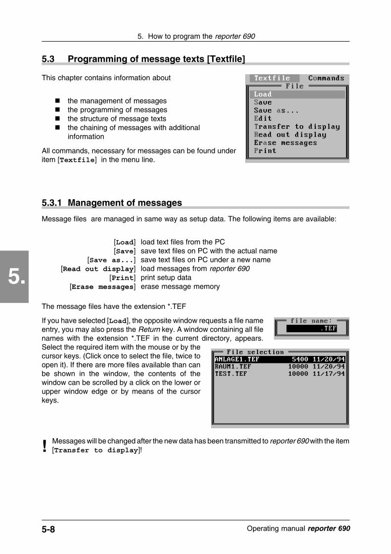
This chapter contains information about
� the management of messages� the programming of messages� the structure of message texts� the chaining of messages with additional
information
All commands, necessary for messages can be found underitem [Textfile] in the menu line.
5.3 Programming of message texts [Textfile]
The message files have the extension *.TEF
If you have selected [Load], the opposite window requests a file nameentry, you may also press the Return key. A window containing all filenames with the extension *.TEF in the current directory, appears.Select the required item with the mouse or by thecursor keys. (Click once to select the file, twice toopen it). If there are more files available than canbe shown in the window, the contents of thewindow can be scrolled by a click on the lower orupper window edge or by means of the cursorkeys.
5.3.1 Management of messages
Message files are managed in same way as setup data. The following items are available:
[Load] load text files from the PC[Save] save text files on PC with the actual name
[Save as...] save text files on PC under a new name[������������� ] load messages from reporter 690
[����] print setup data[����������] erase message memory
! Messages will be changed after the new data has been transmitted to reporter 690 with the item[Transfer to display]!
5-9������������� �����������
5. How to program the reporter 690
5.
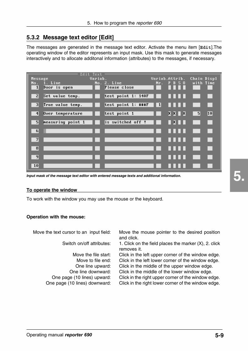
5.3.2 Message text editor [Edit]
The messages are generated in the message text editor. Activate the menu item [Edit].Theoperating window of the editor represents an input mask. Use this mask to generate messagesinteractively and to allocate additonal information (attributes) to the messages, if necessary.
Input mask of the message text editor with entered message texts and additional information.
To operate the window
To work with the window you may use the mouse or the keyboard.
Operation with the mouse:
Move the text cursor to an input field: Move the mouse pointer to the desired positionand click.
Switch on/off attributes: 1. Click on the field places the marker (X), 2. clickremoves it.
Move the file start: Click in the left upper corner of the window edge.Move to file end: Click in the left lower corner of the window edge.One line upward: Click in the middle of the upper window edge.
One line downward: Click in the middle of the lower window edge.One page (10 lines) upward: Click in the right upper corner of the window edge.
One page (10 lines) downward: Click in the right lower corner of the window edge.

5-10 ������������� reporter ��
5. How to program the reporter 690
5.
Operation with the keyboard:
! Use ESC to quit the text editor and to return to the file menu!
Position text cursor: Move to desired position with the cursor keysSwitch on/off attributes: Change with the keys Enter or Space, set with key X
and delete with key DelMove to file start: Press Ctrl and PgUp simultaneouslyMove to file end: Press Ctrl and PgDn simultaneouslyOne line upward: Cursor key Up
One line downward: Cursor key DownOne page (10 lines) upward: Key PgUp
One page (10 lines) downward: Key PgDnMove the cursor one field to the left: Key Tab
Move the cursor one field to the right: Press Shift and Tab simultaneously.Move to line start: Key HomeMove to line end: Key End
Message text addresses
Enter message texts
If a stored message is to be displayed in the normal operation of the reporter 690, it must beinitiated by transmission of its messagfe number. Therefore message numbers and the messagestored in this address are one unit. All 100 storage locations (option 512) are already designatedas input fields. The input mask is numbered successively with the addresses 1 to 100 (512). If youenter, for example, a message into field no. 1, later you may call this message by address no.1.
The fields for message text input are divided into lines 1 and 2. Each line has room for 20alphanumeric characters. This corresponds to the structure of the LCD display of the reporter 690.If you enter the text into the left field it will later appear in the upper line of the display. Texts enteredinto the right field, appear in the lower line. The text appears on the display as you have enteredit in the fields, including blank characters and spaces.
Attention: Do not use the special character "#". It is reserved as a placeholder forvariables (see the following point).!
5-11������������� �����������
5. How to program the reporter 690
5.
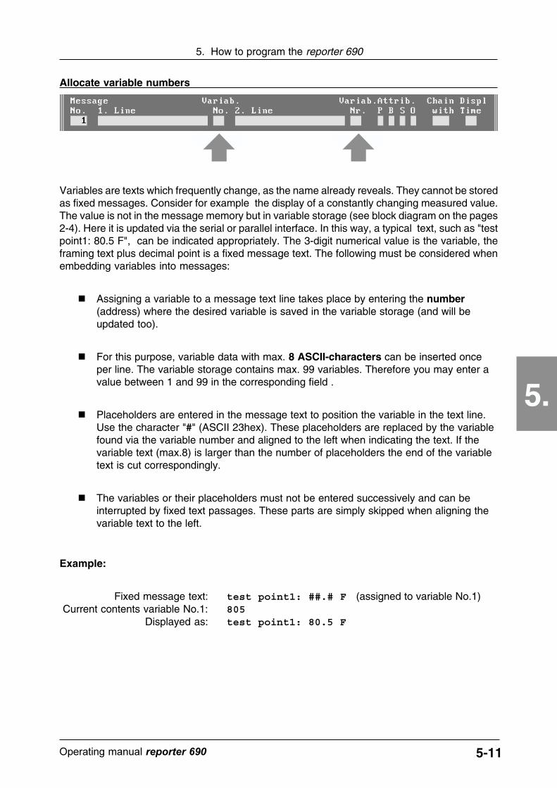
Allocate variable numbers
Variables are texts which frequently change, as the name already reveals. They cannot be storedas fixed messages. Consider for example the display of a constantly changing measured value.The value is not in the message memory but in variable storage (see block diagram on the pages2-4). Here it is updated via the serial or parallel interface. In this way, a typical text, such as "testpoint1: 80.5 F", can be indicated appropriately. The 3-digit numerical value is the variable, theframing text plus decimal point is a fixed message text. The following must be considered whenembedding variables into messages:
� Assigning a variable to a message text line takes place by entering the number(address) where the desired variable is saved in the variable storage (and will beupdated too).
� For this purpose, variable data with max. 8 ASCII-characters can be inserted onceper line. The variable storage contains max. 99 variables. Therefore you may enter avalue between 1 and 99 in the corresponding field .
� Placeholders are entered in the message text to position the variable in the text line.Use the character "#" (ASCII 23hex). These placeholders are replaced by the variablefound via the variable number and aligned to the left when indicating the text. If thevariable text (max.8) is larger than the number of placeholders the end of the variabletext is cut correspondingly.
� The variables or their placeholders must not be entered successively and can beinterrupted by fixed text passages. These parts are simply skipped when aligning thevariable text to the left.
Example:
Fixed message text: test point1: ##.# F (assigned to variable No.1)Current contents variable No.1: 805
Displayed as: test point1: 80.5 F
5-12 ������������� reporter ��
5. How to program the reporter 690
5.
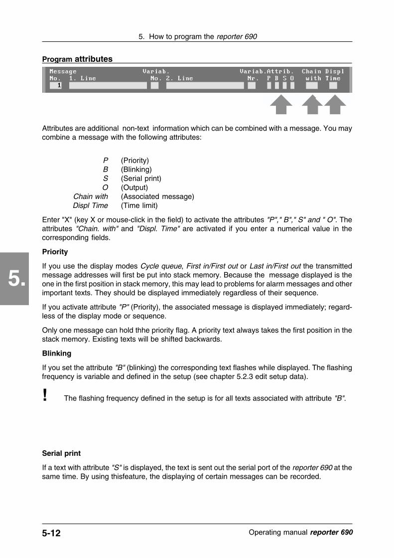
Program attributes
Attributes are additional non-text information which can be combined with a message. You maycombine a message with the following attributes:
P (Priority)B (Blinking)S (Serial print)O (Output)
Chain with (Associated message)Displ Time (Time limit)
Enter "X" (key X or mouse-click in the field) to activate the attributes "P"," B"," S" and " O". Theattributes "Chain. with" and "Displ. Time" are activated if you enter a numerical value in thecorresponding fields.
Priority
If you use the display modes Cycle queue, First in/First out or Last in/First out the transmittedmessage addresses will first be put into stack memory. Because the message displayed is theone in the first position in stack memory, this may lead to problems for alarm messages and otherimportant texts. They should be displayed immediately regardless of their sequence.
If you activate attribute "P" (Priority), the associated message is displayed immediately; regard-less of the display mode or sequence.
Only one message can hold thhe priority flag. A priority text always takes the first position in thestack memory. Existing texts will be shifted backwards.
Blinking
If you set the attribute "B" (blinking) the corresponding text flashes while displayed. The flashingfrequency is variable and defined in the setup (see chapter 5.2.3 edit setup data).
! The flashing frequency defined in the setup is for all texts associated with attribute "B".
Serial print
If a text with attribute "S" is displayed, the text is sent out the serial port of the reporter 690 at thesame time. By using thisfeature, the displaying of certain messages can be recorded.

5-13������������� �����������
5. How to program the reporter 690
5.
Alarm Output
Messages for which the attribute "O" is set, activate the alarm output of the reporter 690 when theyare displayed. The message output remains active as long as the associated message is shownon the display.
Enter default message
The attribute "O" is effective only if the parameter "Output = Normal" is set in the setup thatmeans the message output is not used for acknowledging data transmissions (see chapter5.2.3 edit setup data).
!
Chained message
Depending on the appplication, it can be useful to chain several messages (chained message).Enter the address of the message to be chained with this message in field "Chain with". Anynumber of messages can be chained in sequence.
To switch over from one message to the chained message takes place with the input MPI or bythe message if it has the attribute "Displ. Time" (see next point).
Time limit
If there are messages in the stack message or if they are chained with each other, switch-over tothe next message takes place with the control input MPI (or the key MPI if available). The time limitdesired is allocated to a message by entering a time limit in the field "Displ. Time". Enter themaximum display time in seconds.
If the time limit of a displayed message is expired, the next message in the queue automaticallyappears or the chained message. If there is no chained or waiting message, the default -messageis displayed after expiration of the display time (see next point) .
If no message is requested and all waiting messages are processed, a default message appearsin the display. The default message is message address 100 (512 "with option package").
5-14 ������������� reporter ��
5. How to program the reporter 690
5.
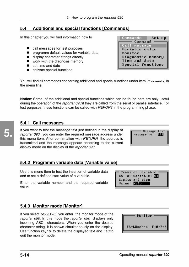
5.4 Additional and special functions [Commands]
In this chapter you will find information how to
� call messages for test purposes� programm default values for variable data� display character strings directly� work with the diagnosis memory� set time and date� activate special functions
You will find all commands concerning additional and special functions under item [Commands] inthe menu line.
Notice: Some of the additional and special functions which can be found here are only usefulduring the operation of the reporter 690 if they are called from the serial or parallel interface. Fortest purposes, these functions can be called with REPORT in the programming phase.
5.4.1 Call messages
If you want to test the message text just defined in the display ofreporter 690 , you can enter the required message address underthis menu item. After confirmation with RETURN the address istransmitted and the message appears according to the currentdisplay mode on the display of the reporter 690.
5.4.2 Programm variable data [Variable value]
Use this menu item to test the insertion of variable dataand to set a defined start value of a variable.
Enter the variable number and the required variablevalue.
5.4.3 Monitor mode [Monitor]
If you select [Monitor] you enter the monitor mode of thereporter 690. In this mode the reporter 690 displays onlyincoming ASCII characters. When you enter the desiredcharacter string, it is shown simultaneously on the display.Use function keyF6 to delete the displayed text and F10 toquit the monitor mode.

5-15Operating manual reporter 690
5. How to program the reporter 690
5.
5.4.4 Optional diagnostic memory [Diagnostic memory]
If you program the version of reporter 690 "with optionpackage", you can edit the diagnosis memory under this menuitem. You may
� read-out the diagnostic memory� save the contents of the diagnostic memory as a file� print the contents of the diagnostic memory� delete the diagnostic memory
Diagnostic memory files are saved with the extension *.DIG .
The diagnostic memory records the data traffic between reporter 690 and the control. Up to 100transmission protocols can be saved in this memory.
The storage takes place in the format date, time, set number. If the storage volume is exceededthe error code 14 will be displayed (see chapter 6.2.3).
Date Time Number
18.12.94 15:32 [08]
20.12.94 15:35 [01]
20.12.94 15:50 [01]
20.12.94 16:02 [07]
Print-out of the diagnosic memory
5.4.5 Set time and date (optional) [Time and date]
The reporter 690 "with option package" has a battery-backed real-time clock. Under this menu item time and date can be read-out orset.
5-16 Operating manual reporter 690
5. How to program the reporter 690
5.
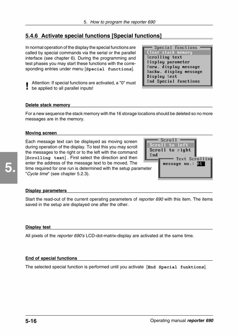
5.4.6 Activate special functions [Special functions]
In normal operation of the display the special functions arecalled by special commands via the serial or the parallelinterface (see chapter 6). During the programming andtest phases you may start these functions with the corre-sponding entries under menu [Special functions].
Attention: If special functions are activated, a "0" mustbe applied to all parallel inputs!!
Delete stack memory
For a new sequence the stack memory with the 16 storage locations should be deleted so no moremessages are in the memory.
Moving screen
Each message text can be displayed as moving screenduring operation of the display. To test this you may scrollthe messages to the right or to the left with the command[Scrolling text] . First select the direction and thenenter the address of the message text to be moved. Thetime required for one run is determined with the setup parameter"Cycle time" (see chapter 5.2.3).
Display parameters
Start the read-out of the current operating parameters of reporter 690 with this item. The itemssaved in the setup are displayed one after the other.
Display test
All pixels of the reporter 690's LCD-dot-matrix-display are activated at the same time.
End of special functions
The selected special function is performed until you activate [End Special funktions].
5-17Operating manual reporter 690
5. How to program the reporter 690
5.
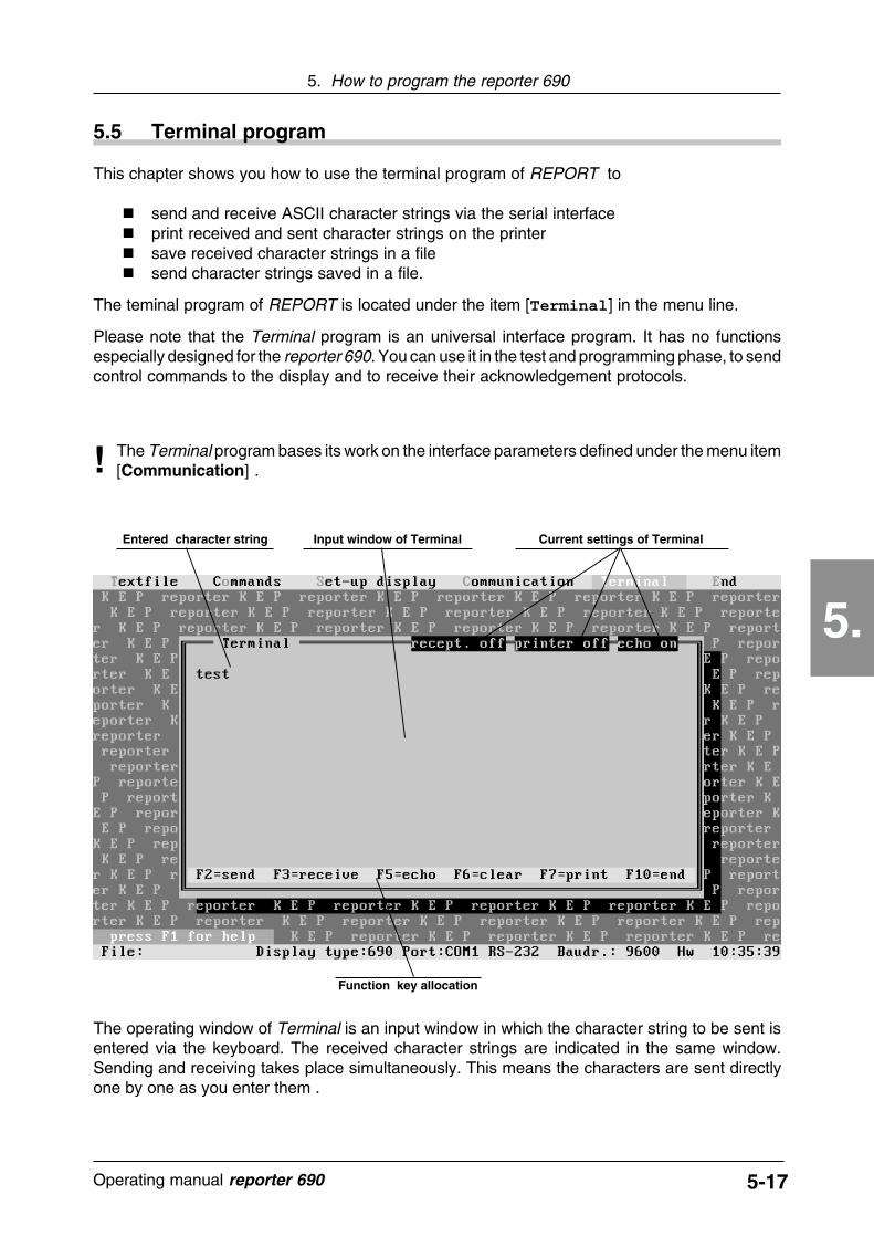
This chapter shows you how to use the terminal program of REPORT to
� send and receive ASCII character strings via the serial interface� print received and sent character strings on the printer� save received character strings in a file� send character strings saved in a file.
The teminal program of REPORT is located under the item [Terminal] in the menu line.
Please note that the Terminal program is an universal interface program. It has no functionsespecially designed for the reporter 690. You can use it in the test and programming phase, to sendcontrol commands to the display and to receive their acknowledgement protocols.
5.5 Terminal program
The Terminal program bases its work on the interface parameters defined under the menu item[Communication] .!
The operating window of Terminal is an input window in which the character string to be sent isentered via the keyboard. The received character strings are indicated in the same window.Sending and receiving takes place simultaneously. This means the characters are sent directlyone by one as you enter them .
Function key allocation
Entered character string Current settings of TerminalInput window of Terminal
5-18 Operating manual reporter 690
5. How to program the reporter 690
5.
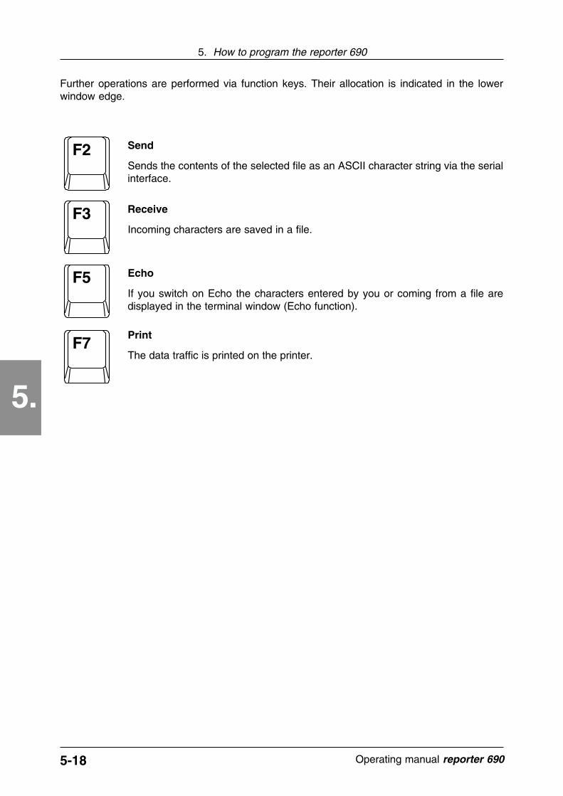
F2
F3
F5
F7Print
The data traffic is printed on the printer.
Echo
If you switch on Echo the characters entered by you or coming from a file aredisplayed in the terminal window (Echo function).
Receive
Incoming characters are saved in a file.
Send
Sends the contents of the selected file as an ASCII character string via the serialinterface.
Further operations are performed via function keys. Their allocation is indicated in the lowerwindow edge.

6-1������������� �����������
6. How to operate the reporter 690
6.
6. How to operate the reporter 690
In this chapter you will learn how to
� select message numbers� transfer variable values� activate special functions
via the serial and parallel interface.
The reporter 690 is operated from a control unit (PLC, computer, wired logic, etc.). Control maybe performed via the serial as well as via the parallel interface of the display. This depends on therequirements of the total system. When control takes place via a PLC, limit switch, relay orsomething similar, the parallel interface is used. If the reporter 690 is part of a system with a centralcontrol computer data transfer takes place via the serial interface.
The parallel interface of the reporter 690 enablessimple activation without strict signal and protocolrequirements. Some characteristics of the parallelinterface depend on the setting in the setup.
Following you will find a summary of the mostimportant points concerning the parallel interface:
Zyk
lus
Str
ob
e
SF
I
MP
I
E1
E2
E3
E4
E5
E6
E7
E8
E9
1 1312111098765432 14
Var
iab
le
Connection: 14-pole terminal block (see chapter 3.3)
Signal level: Digital control (0/1), related to the operating voltage,0=Gnd, 1=+On. Inputs not used (open inputs) arerecognized as level "0" (see chapter 3.3).
Data inputs: Connections E1...E8 (E9 with option package)
Decoding of data inputs: BCD or binary code, according to setup setting (seechapter 5.2.3)
Data strobe: Static (without control signal) or dynamic (withcontrol signal) Strobe, according to setup setting(see chapter 5.2.3)
Control inputs: Strobe - Data strobe signalVariable - Identification for variable transferSFI - Identification for special functionsMPI - Acknowledgement input
6.1 Control via the parallel interface

6-2 ������������� reporter ��
6. How to operate the reporter 690
6.
6.1.1 Call-in message texts
Summary of the most important points about message texts:
� 100 message texts maximum (512 with option package)
� One message texts includes 2 lines with max. 20 characters each
� The message texts are pre-programmed (with REPORT programming software) andare located in the message text memory of the reporter 690 (see chapter 5.3.2)
� Message texts can be provided with the attributes "P" (Priority), "B" (Blinking), "S"(Serial print), "O" (Output), "Chain. with" (Associated message) and "Displ. Time"(Time limit) (see chapter 5.3.2)
� Message texts can be indicated in the 4 operating modes "Direct message", "Cyclequeue", "First in/First out", or "Last in/First out", according to the setup setting (seechapter 5.2.3)
� Message texts may also include variable data
� Messages are called by transmission of their memory address
� If no message is called, either directly or via the stack memory, the standby messageappears (programmed in the message address 100 or with option package in address512)
� Messages in the queue of the stack memory and/or associated messages can beswitched with the input MPI
� The operating key of the reporter 690, if released in the setup, has the same functionas the input MPI
� Message requests in the stack memory are lost when switching off the operatingvoltage
To display a message text, the message address must be applied to the data inputs in binary orBCD. A rising edge at the control input Strobe activates the address. After the internal processing(in milliseconds), the corresponding message appears on the display. If you select the static datastrobe (disable strobe signal) in the setup, a message text address need only be applied to activatethe message. The following example shows how a display can be shown in this way.
Example:
In a clinic the reporter 690 is used for the monitoring and status display of an entrance gate to asensitive operating area. The automatic doors are controlled by limit switches. Therefore no"intelligent" control like a PLC or a computer system is responsible for the display.
Wiring, programming of the message texts and the setup settings are as follows:

6-3������������� �����������
6. How to operate the reporter 690
6.
Cyc
le
Str
ob
e
SF
I
MP
I
E1
E2
E3
E4
E5
E6
E7
E8
E9 +
11-3
0V
- E C
1 1312111098765432 14 1 2 3 4 5 6
Var
iab
le1
Connection to reporter 690:
Buzzer(24V)
anteroom
OP
Door contacts for
GND
+24VDC
Operating voltage
Programmed message texts:
Setup settings: Display mode Direct message (instantaneous value)Binary/BCD binary
Strobe without Strobe (statical)Output normal
- If neither of the two limit switches are active, the standby text will be displayed.- If limit switch 1 is active, message text No. 1 will be displayed.- If limit switch 2 is active, message text No. 2 will be displayed.- If both limit switches are active, a binary "3" is at the input and message No. 3 will be
displayed. Because this message has the attributes "O" (Output) and "B" (Flashing)the text flashes on the display and the alarm output of the reporter 690 is active thatmeans the buzzers are sounding.
Function of the text display:
TxD
RxD
GN
D
RT
SC
TS
RS-232
6-4 ������������� reporter ��
6. How to operate the reporter 690
6.
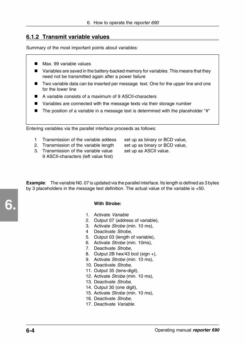
6.1.2 Transmit variable values
Summary of the most important points about variables:
� Max. 99 variable values
� Variables are saved in the battery-backed memory for variables. This means that theyneed not be transmitted again after a power failure
� Two variable data can be inserted per message text. One for the upper line and onefor the lower line
� A variable consists of a maximum of 9 ASCII-characters
� Variables are connected with the message texts via their storage number
� The position of a variable in a message text is determined with the placeholder "#"
Entering variables via the parallel interface proceeds as follows:
1 Transmission of the variable addess set up as binary or BCD value,2. Transmission of the variable length set up as binary or BCD value,3. Transmission of the variable value set up as ASCII value.
9 ASCII-characters (left value first)
Example: The variable N0. 07 is updated via the parallel interface. Its length is defined as 3 bytesby 3 placeholders in the message text definition. The actual value of the variable is +50.
With Strobe:
1. Activate Variable2. Output 07 (address of variable),3. Activate Strobe (min. 10 ms),4 Deactivate Strobe,5. Output 03 (length of variable),6. Activate Strobe (min. 10ms),7. Deactivate Strobe,8. Output 2B hex/43 bcd (sign +),9. Activate Strobe (min. 10 ms),10. Deactivate Strobe,11. Output 35 (tens-digit),12. Activate Strobe (min. 10 ms),13. Deactivate Strobe,14. Output 30 (one digit),15. Activate Strobe (min. 10 ms),16. Deactivate Strobe,17. Deactivate Variable.

6-5������������� �����������
6. How to operate the reporter 690
6.
6.1.3 Activate special functions
To activate the additional or special functions via the parallel interface, two declarations are used:
� a code which describes the respective special function and� a control signal which identifies the set bit pattern as the code for the special function.
00 Display of all parameters01 Display test02 Monitor mode03 Forward output text
Control Code Spec. function
04 Backward output text05 Test input signals06 Test control signals07 Delete stack memory09 Read out diagnosis memory
Control codes for special functions.The control signal is the connection SFI,the code is shown in the opposite list.
The signal SFI must be present aslong as the special function is to becarried out. The operating mode"Special Function" is completedwhen SFI is deactivated and thesignal Strobe is activated. The inputsignals applied at this moment areidentified as message text addres-ses.
!
Notice:The special functions Test input signals and Test control signals are not included in theREPORT programming software and consequently are not described there. Their function is asfollows:
Test input signals The level (0/1) of the inputs E1...E9 is indicated on the display.
Test control signals The current level (0/1) of the control inputs Variable, Cycle, MPI, SFIis indicated on the display.
Example: Calling of the special function 03 (Output of all saved messages).
With Strobe:
1. Activate SFI2. Output code 033. Activate Strobe (Acceptance of
the special function)4. Deactivate Strobe (Strobe
pulse duration min. 10ms)5. Deactivate SFI (special
function is completed)6. Activate Strobe
Without Strobe:
1. Activate SFI2. Output code 03 (after internal
delay time acceptance of thespecial function)
3. Deactivate SFI (special function iscompleted)
4. Activate Strobe
6-6 ������������� reporter ��
6. How to operate the reporter 690
6.
6.2 Control via the serial interface
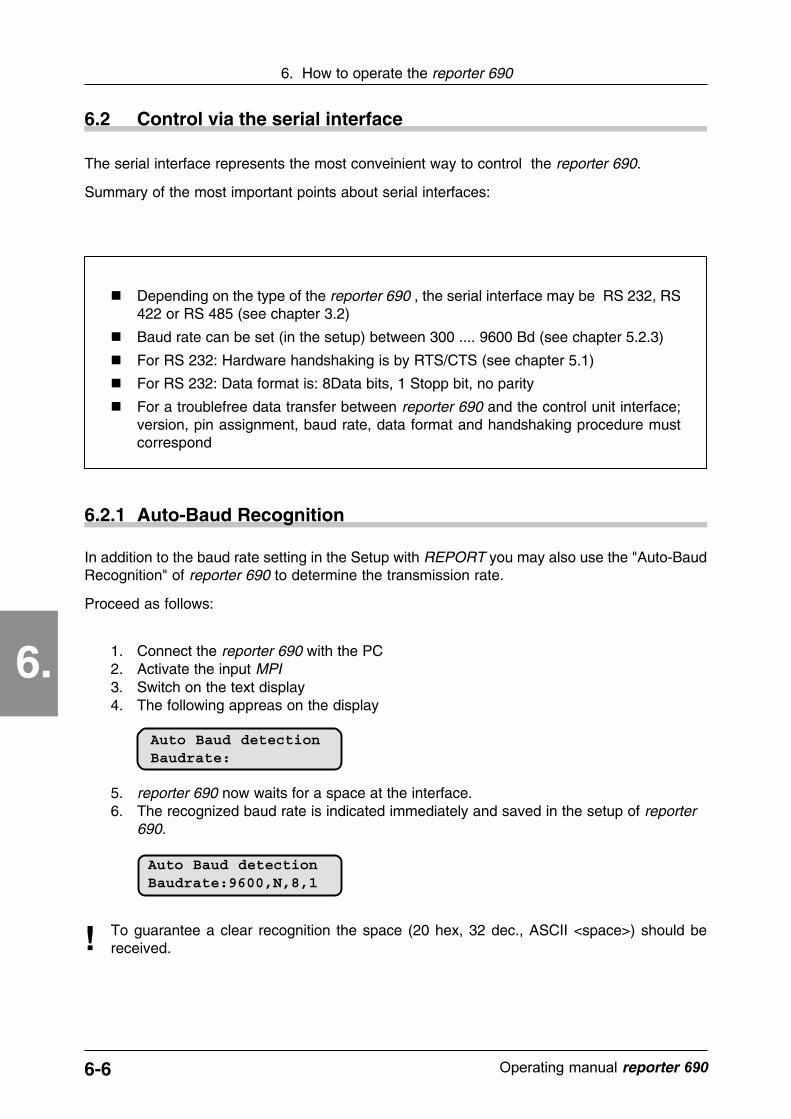
In addition to the baud rate setting in the Setup with REPORT you may also use the "Auto-BaudRecognition" of reporter 690 to determine the transmission rate.
Proceed as follows:
1. Connect the reporter 690 with the PC2. Activate the input MPI3. Switch on the text display4. The following appreas on the display
To guarantee a clear recognition the space (20 hex, 32 dec., ASCII <space>) should bereceived.!
5. reporter 690 now waits for a space at the interface.6. The recognized baud rate is indicated immediately and saved in the setup of reporter
690.
6.2.1 Auto-Baud Recognition
Auto Baud detectionBaudrate:9600,N,8,1
Auto Baud detectionBaudrate:
The serial interface represents the most conveinient way to control the reporter 690.
Summary of the most important points about serial interfaces:
� Depending on the type of the reporter 690 , the serial interface may be RS 232, RS422 or RS 485 (see chapter 3.2)
� Baud rate can be set (in the setup) between 300 .... 9600 Bd (see chapter 5.2.3)
� For RS 232: Hardware handshaking is by RTS/CTS (see chapter 5.1)
� For RS 232: Data format is: 8Data bits, 1 Stopp bit, no parity
� For a troublefree data transfer between reporter 690 and the control unit interface;version, pin assignment, baud rate, data format and handshaking procedure mustcorrespond

6-7������������� �����������
6. How to operate the reporter 690
6.
6.2.2 Data transmission protocol
An exactly defined data format is used for the communication between reporter 690 and the controlunit.
A data sequence different from the protocol is rejected by the display with an error code!
The error code is returned to the control unit via the interface and indicated for 5 seconds on thedisplay.
!
The transmission block starts with the
Start characters ESC (1Bh).
For RS 422/485 the
Device address
of the device to be addressed must follow then. Afterthis start sequence a
Control code,
follows, which describes the required function. Afterthat one or several
Data bytes.
follow. The transmission is completed with the endsequence
Carriage Return (0Dh)
and
Line feed (0Ah)
Start character <ESC>1Bh
Only RS 422/485:Device address 00..0Fh
< Carriage Return>0Dh
<Line Feed>0Ah
Control code
Data byte(s)
For a better readability of the transmission protocol, the separators [;] semicolon and [:] colon canbe inserted and sent together with the transmission. These characters will be overlooked.
All alphanumerical values as control code, device address, figures and data which will betransmitted between reporter 690 and the control , are in ASCII-Code!
If the reporter 690 in its current version does not have a function available as requested by thecontrol code, an error message is displayed!
!
Example: The data byte 03 is transmitted to the reporter 690. The function belonging to thisinformation has the control code 8. According to RS 422 or RS 485 the device address of thedisplay to be addressed is 2.
ASCII sequence for RS 232: <ESC>8,03<CR><LF>
ASCII sequence for RS 422/485: <ESC>2,8,03<CR><LF>
Note: This protocol and the control characters are generally valid for serial control of the reporter690. It is also used by the REPORT programming software. Therefore, all functions, includingprogramming and setup, can be performed by the software. You will find an overview of all controlcodes in Appendix A.

6-8 ������������� reporter ��
6. How to operate the reporter 690
6.
6.2.3 Data-acknowledgement
If an instruction sequence has been received and interpreted without any errors, the reporter 690sends a <CR> <LF> as acknowledgement to the sending unit. If the instruction did not correspondto the transmission protocol or if other transmission errors occured, a 2-digit error code (see table)will be returned to the control. The error is indicated for 5 seconds on the display of the text display.
01 Syntax error in the received byte02 Received byte faulty03 Message number invalid04 Function not allowed
Error code Cause
05 Data transmission error06 Inadmissible program function of the MPI input07 Error when writing into the EEPROM08 Mode not available09 Message number is missing10 Overflow message stack11 Error length specification12 Interface address (RS 422/485) faulty13 Variables faulty
Error code after a serial data transmission
Acknowledgement example:
Response of the reporter 690 after a correct data transmission:
<CR><LF> (Hex: 0D,0A)
Response of the reporter 690 after a transmission with a syntax error:
01<CR><LF> (Hex: 30,31,0D,0A)
Simultaneous message on the text display (approx. 5s):
Communication errorSyntax error
14 Diagnosis memory complete
6-9������������� �����������
6. How to operate the reporter 690
6.
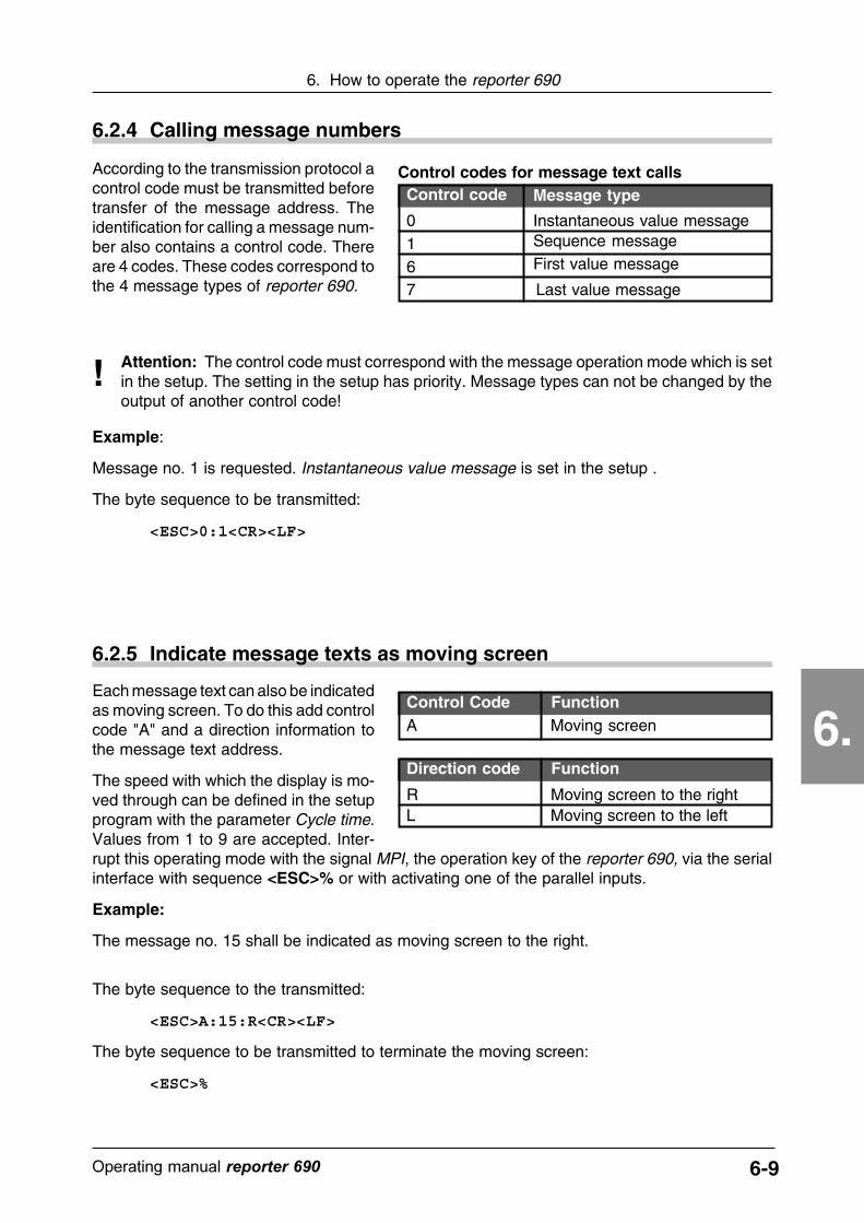
6.2.4 Calling message numbers
According to the transmission protocol acontrol code must be transmitted beforetransfer of the message address. Theidentification for calling a message num-ber also contains a control code. Thereare 4 codes. These codes correspond tothe 4 message types of reporter 690.
0167
Control codeControl codes for message text calls
Attention: The control code must correspond with the message operation mode which is setin the setup. The setting in the setup has priority. Message types can not be changed by theoutput of another control code!
!
Example:
Message no. 1 is requested. Instantaneous value message is set in the setup .
The byte sequence to be transmitted:
<ESC>0:1<CR><LF>
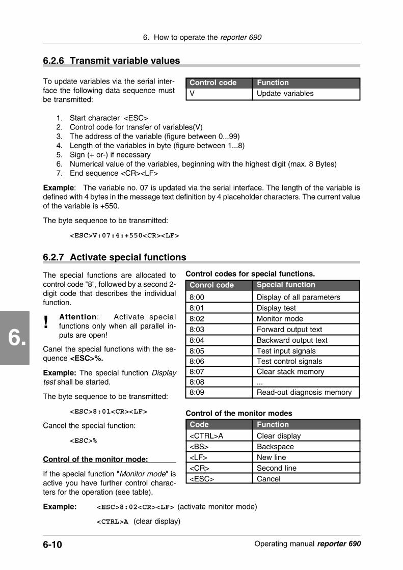
6.2.5 Indicate message texts as moving screen
Each message text can also be indicatedas moving screen. To do this add controlcode "A" and a direction information tothe message text address.
The speed with which the display is mo-ved through can be defined in the setupprogram with the parameter Cycle time.Values from 1 to 9 are accepted. Inter-rupt this operating mode with the signal MPI, the operation key of the reporter 690, via the serialinterface with sequence <ESC>% or with activating one of the parallel inputs.
Example:
The message no. 15 shall be indicated as moving screen to the right.
Control Code Function
R Moving screen to the right
Direction code Function
L Moving screen to the left
A Moving screen
The byte sequence to the transmitted:
<ESC>A:15:R<CR><LF>
The byte sequence to be transmitted to terminate the moving screen:
<ESC>%
Message type
Instantaneous value message
First value message
Last value message
Sequence message
6-10 ������������� reporter ��
6. How to operate the reporter 690
6.
6.2.6 Transmit variable values
Control code FunctionV Update variables
To update variables via the serial inter-face the following data sequence mustbe transmitted:
1. Start character <ESC>2. Control code for transfer of variables(V)3. The address of the variable (figure between 0...99)4. Length of the variables in byte (figure between 1...8)5. Sign (+ or-) if necessary6. Numerical value of the variables, beginning with the highest digit (max. 8 Bytes)7. End sequence <CR><LF>
Example: The variable no. 07 is updated via the serial interface. The length of the variable isdefined with 4 bytes in the message text definition by 4 placeholder characters. The current valueof the variable is +550.
The byte sequence to be transmitted:
<ESC>V:07:4:+550<CR><LF>
6.2.7 Activate special functions
8:00 Display of all parameters8:01 Display test8:02 Monitor mode8:03 Forward output text
Conrol code Special function
8:04 Backward output text8:05 Test input signals8:06 Test control signals8:07 Clear stack memory8:08 ...8:09 Read-out diagnosis memory
Control codes for special functions.The special functions are allocated tocontrol code "8", followed by a second 2-digit code that describes the individualfunction.
Attention: Activate specialfunctions only when all parallel in-puts are open!
!Canel the special functions with the se-quence <ESC>%.
Example: The special function Displaytest shall be started.
The byte sequence to be transmitted:
<ESC>8:01<CR><LF>
Cancel the special function:
<ESC>%
Control of the monitor mode:
If the special function "Monitor mode" isactive you have further control charac-ters for the operation (see table).
Example: <ESC>8:02<CR><LF> (activate monitor mode)
<CTRL>A (clear display)
Control of the monitor modes
<CTRL>A Clear display<BS> Backspace<LF> New line<CR> Second line<ESC> Cancel
FunctionCode
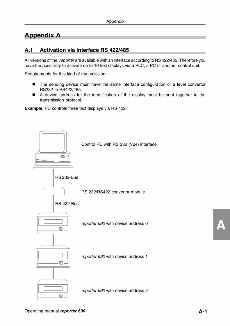
A-1������������� �����������
Appendix
A
RS 232/RS422 convertor module
reporter 690 with device address 0
reporter 690 with device address 1
reporter 690 with device address 2
RS 422-Bus
RS 232-Bus
Appendix A
All versions of the reporter are available with an interface according to RS 422/485. Therefore youhave the possibility to activate up to 16 text displays via a PLC, a PC or another control unit.
Requirements for this kind of transmission:
� The sending device must have the same interface configuration or a level convertorRS232 to RS422/485.
� A device address for the identification of the display must be sent together in thetransmission protocol.
Example: PC controls three text displays via RS 422.
A.1 Activation via interface RS 422/485
Control PC with RS 232 (V24) interface

A-2 ������������� reporter ��
Appendix
A
A.2 Overview of the control codes
FunctionControl codes of the serial interfaceCode
0 Direct message (Instantaneous value message)Example: Calling the message number address 05. 0:05
1 Cycle message (Sequence message)Example: Entry of message number add. 33 into the memory stack. 1:33
6 First in/First out (First value message)Message acknowledgement only with signal MPI, not with oper.key.Example: Entry of message number add. 05 into the memory stack. 6:05
7 Last in/First out (Last value message)Message acknowledgement only with MPI signal, not with oper. key.Example: Entry of message number add. 17 into the memory stack. 7:17
8 Special functions via the serial interface.Attention: To be called only, if all parameter inputs are open.Cancel with sequence <ESC>%Display of all parameters 8:00Display test 8:01Monitor mode (all incomming characters are displayed immediately) 8:02
<CTRL>A clears the display<BS> Backspace<LF> New line<CR> Second line<ESC> Cancel
Text memory output forward: Beginning with 1...99 (511) 8:03Text memory output backward: Beginning with 99...1 (511) 8:04Test input signals: E1..E8(9) 8:05Test control signals: MPI, SFI, VAR, ZYKL, key 8:06Delete stack memory 8:07Read out diagnosis memory (only with option package) 8:09
9 Set time (only with option package)Sequence: Sec., Min., Hour Example: 23h 59.00 9:00:59:23
A Moving screen to the left A:22:LMoving screen to the right Example text no. 22 A:22:R
S Change setup parameters00 Baud rate 2...7: (9600, 4800, 2400, 1200, 600, 300) S:00:xx01 Strobe 0 = without Strobe, 1 = with Strobe S:01:xx02 Beeper 0 = without beeper, 1 = with beeper S:02:xx03 MPI 0 = only MPI, 1 = oper. key or MPI S:03:xx04 Binary/BCD 0 = Binary, 1 = BCD S:04:xx05 Mode 0,1,6,7 = corresp. display modes S:05:xx06 Output 0 = Normal, 1 = Acknowledg. S:06:xx07 Language 0 = German, 1 = English, 2 = French S:07:xx08 Flashing freq. 2...50 = Flashing frequency S:08:xx09 Delay input 2...99 = time in 10ms S:09:xx0A Cycle time 1...9 S:0A:xx0C Device addr. 0..0F = Address S:0C:xx
V Continuous displaying of variable data1.Byte = Num. of variable, 2.Byte = Length, 3..11 Byte = Value of var.Example: Update of variables no. 01 to +50 V:01:3:+50
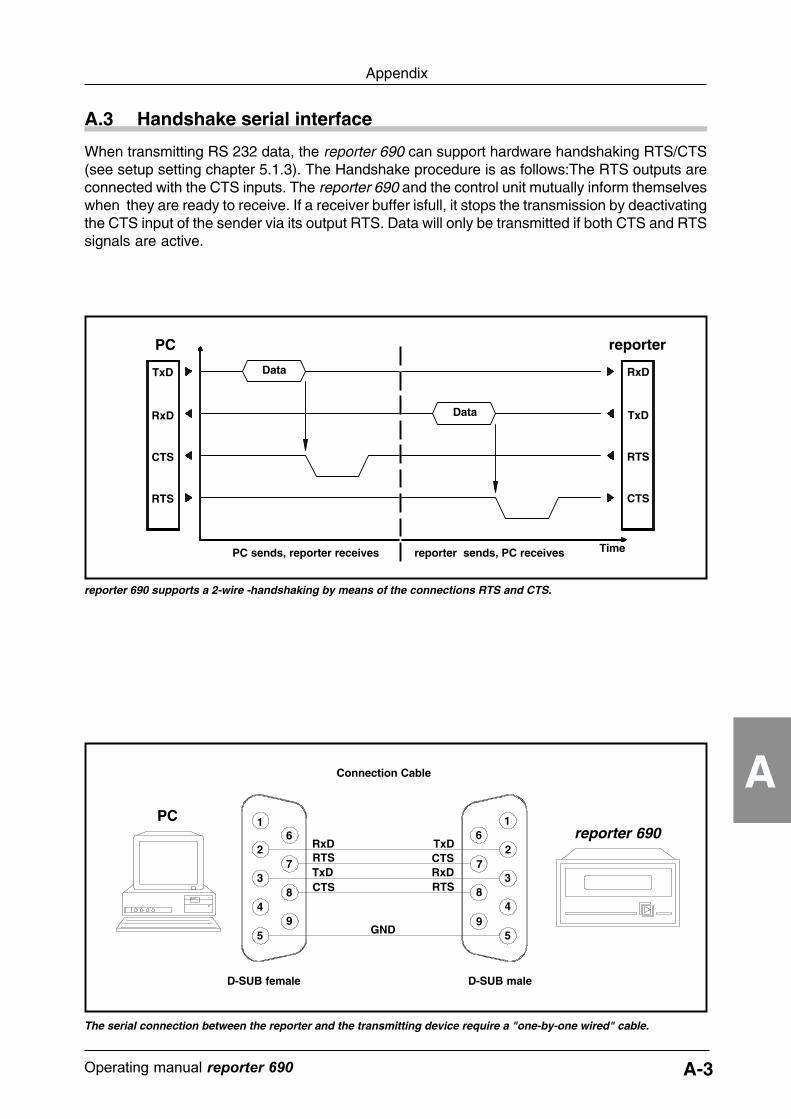
A-3������������� �����������
Appendix
A
A.3 Handshake serial interface
When transmitting RS 232 data, the reporter 690 can support hardware handshaking RTS/CTS(see setup setting chapter 5.1.3). The Handshake procedure is as follows:The RTS outputs areconnected with the CTS inputs. The reporter 690 and the control unit mutually inform themselveswhen they are ready to receive. If a receiver buffer isfull, it stops the transmission by deactivatingthe CTS input of the sender via its output RTS. Data will only be transmitted if both CTS and RTSsignals are active.
RxD
TxD
CTS
RTS
TxD
RxD
RTS
CTS
reporterPC
Time
Data
Data
PC sends, reporter receives reporter sends, PC receives
reporter 690 supports a 2-wire -handshaking by means of the connections RTS and CTS.
D-SUB maleD-SUB female
The serial connection between the reporter and the transmitting device require a "one-by-one wired" cable.
2
1
3
4
5
6
7
8
9
Connection Cable
PCreporter 690
1
2
3
4
5
6
7
8
9
RTS
TxD
RxDCTS
RxDRTSTxDCTS
GND
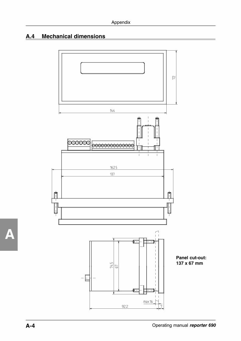
A-4 ������������� reporter ��
Appendix
A
A.4 Mechanical dimensions
Panel cut-out:137 x 67 mm

A-5������������� �����������
Appendix
A
A.5 Pin configuration
2 Transmitted dataTxD3 Received dataRxD8 Request to sendRTS7 Clear to sendCTS5 GroundGND
Pin number Symbol FunctionPin assignment of the 9-pole SUB-D-socket RS232
1 Control signal (Variable)Variable2 Not usedCycle3 Control signal (message text)Strobe4 Acknowledgement inputMPI
Terminal Symbol Function
5 Control signal (special function)SFI6 ... 14 Address inputs for message numbersE1 ... E9
Pin assignment of the 14-pole screw-type terminal
1 Positive operating voltage connection+2 Negative operating voltage connection-3 Connection for ground
Terminal Symbol FunctionPin assignment of the 6-pole screw-type terminal
Relay: Center contact Opto-coupler: EmitterE5 Relay: Make contact Opto-coupler: CollectorC6 Relay: Break contact Opto-coupler: -
4
Zyk
lus
Str
ob
e
SF
I
MP
I
E1
E2
E3
E4
E5
E6
E7
E8
E9 +
11-3
0V
- E C
1 1312111098765432 14 1 2 3 4 5 6
Var
iab
le1
RS-232
TxD
RxD
GN
D
RT
SC
TS

A-6 ������������� reporter ��
Appendix
A
Technical data reporter 690
Display LCD with background illumination, 2 x 20 characters, dot matrix 5x7 dots,international character set (PC 437) with special characters.
Text memory For 100 (option 512) 2 line texts with attributes (flashing, alarm, printtime limit, connection, priority).
A.6 Technical data
Stack memory 16 (option 32) messages.
Parallel inputs Binary: 8 bit for 100 messages (option 9 bit for 512 messages)BCD: 8 Bit for 100 messages (option 9 bit for 199 messages).
Parallel inputs,electr. data
Polarity: PNP, input resistance: 5.6 kOhm, minimum pulse time:1ms, switching level: Log "0": 0..0.2 x Ub. Log. "1": 0.55 x Ub..30V,pulse form: any, as Schmitt-Trigger inputs.
Serial interface RS 232 (option RS 422/485), 9600 Baud, 8 data bits, 1 Stop bit, noparity, automatic baud rate identification after a transmitted character.
Message types Instantaneous value display, sequence message (cycle display), firstvalue display, last value display.
Inserting ofvariables
Memory for 99 variables with max. 9 ASCII-characters which can beinserted into message texts.
Special functions 9 special functions can be called, error code display.
Setup memory All function parameter can be saved in the setup.
Output 1 progr. multi purpose output for alarm or acknowledgement output.Available as:NPN opto-coupler with open collector and emitter, switching capacity:30VDC / 15mA (UCEsat for IC=15 mA: max. 2V, UCEsat for IC = 5mA: max.0,4V).or as:Relay with potential free change-over contact, switching voltage max.250VAC/30VDC, switching current max. 3A AC/DC, switching capacitymax. 50W for DC, min. switching current for DC: 30mA.Response time output: Relay:approx. 6ms, Opto-coupler:approx. 1ms.
Beeper Acknowledgement signal.
Operating key
Option package Diagnosis memory for 100 transactions, battery-backed real time clock,memory extension to 512 messages and 32 stack positions.
Voltage supply-versorgung
11...30 VDC unregulated, max. 3W.
Data securing 10 years
Housing dimens. DIN 144 x 72 x 90 mm
Weight
Internationalprotection
IP 65 from the front, IP 20 from the rear600 gram
1 prog. key for acknowledgement.
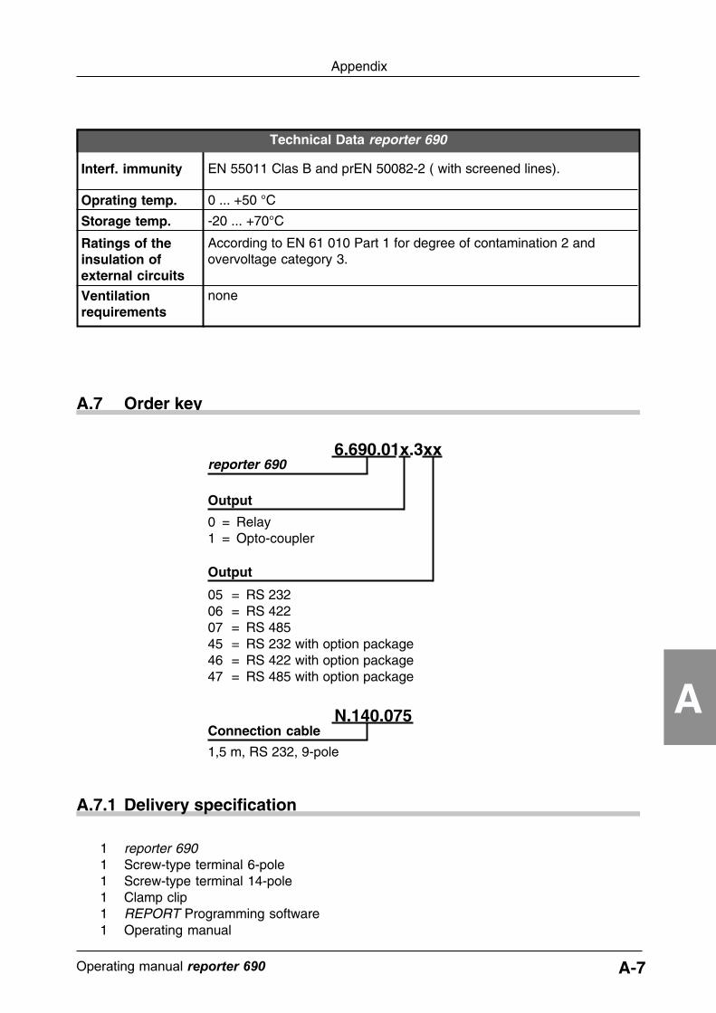
A-7������������� �����������
Appendix
A
A.7.1 Delivery specification
1 reporter 6901 Screw-type terminal 6-pole1 Screw-type terminal 14-pole1 Clamp clip1 REPORT Programming software1 Operating manual
A.7 Order key
Technical Data reporter 690
Oprating temp. 0 ... +50 °C
Storage temp. -20 ... +70°C
Ratings of theinsulation ofexternal circuits
According to EN 61 010 Part 1 for degree of contamination 2 andovervoltage category 3.
Ventilationrequirements
none
Interf. immunity EN 55011 Clas B and prEN 50082-2 ( with screened lines).
N.140.075Connection cable
1,5 m, RS 232, 9-pole
reporter 690
Output
Output
0 = Relay1 = Opto-coupler
05 = RS 23206 = RS 42207 = RS 48545 = RS 232 with option package46 = RS 422 with option package47 = RS 485 with option package
6.690.01x.3xx

Operating manual reporter 690
Index
Operating manual reporter 690
Index
Index
Aacknowledgement 5-6alarm output 1-1, 2-5, 5-13attributes 2-5, 5-12auto-baud recognition 6-6
Bbattery-backed 5-15baud rate 5-1, 5-3BCD code 5-5Binary/BCD 5-5blink rate 5-7blinking 2-5, 5-12block diagram 2-4buzzer 5-7
Ccall messages 5-14chained message 5-13character set 5-7cleaning 1-2communications type 5-1connection 2-1, 2-5, 3-1control codes A-2cursor keys 4-4cycle queue 5-4cycle time 5-7, 6-9
Ddata-acknowledgement 6-8date 5-15default message 5-13delay time 5-6delivery specification A-7device address 5-3diagnostic memory 5-3, 5-15direct message 5-4display parameters 5-16display test 5-16
Eerror code 6-8extended memory 5-3extended stack memory 5-3
Ffire protection 3-1first in/first out 5-4first value display 2-3front side 2-2function keys 5-18function overview 2-3
Hhandshake serial interface A-3hotkeys 4-4
Iinput delay 5-6installation program 4-1instantaneous value 5-4intended purpose 1-1interface parameters 5-1interfaces 2-5interference immunity 3-1
Kkeyboard 4-4
Llast in/first out 5-4last value 5-4last value display 2-3
Mmanagement of messages 5-8mechanical dimensions A-4menu 4-3menu item 4-3menu line 4-2message files 5-8message mode 5-4message number 2-3, 6-9message output 3-4message text addresses 5-10message text calling 5-4message text editor 5-9message texts 2-3, 5-8, 6-2, 6-9monitor mode 5-14
Operating manual reporter 690
Index
monitor modes 6-10moving screen 5-7, 5-16, 6-9MPI 6-9
Nnumber PC interface 5-1
OOn line help 4-4operating elements 2-1operating instructions 4-2operating key MPI 5-7operating modes 5-5option package 2-6, 5-3option set 5-3opto-coupler 3-4order key A-7output 2-5, 5-6
Pparallel data transmission 5-6parallel inputs 3-3parallel interface 2-5, 5-5, 6-1pin configuration A-5placeholders 5-11power supply 3-1power-on message 5-7print 2-5priority 2-5, 5-12programming software 2-6, 4-1protective earth ground 3-1pulse length 5-5
Qqueued 5-4
Rreal-time clock 5-3, 5-15rear side 2-2relay limits 3-4RS 232 3-2RS 422 3-2, 5-3, A-1RS 485 3-2, 5-3
Ssafety notes 1-1safety precautions 1-1
safety regulations 1-2selected menu item 4-3sequence display 2-3sequenced list 5-4serial connection A-3serial interface 2-5, 6-6serial interface connection 3-2serial port 5-1serial port status 5-2serial print 2-5, 5-12set-up 5-2setup data 5-3setup memory 2-5shielded cable 3-3signal allocation 5-5signal voltage 3-3special functions 2-5, 5-14, 5-16, 6-5, 6-
10stack memory 2-3, 5-5, 5-16state interface 5-2status line 4-3strobe input 5-5strobe signal 5-5, 5-6supply voltage 3-1switching load 3-4system environment 4-1
Ttechnical data A-6terminal program 5-17text addresses 2-3textfile 5-8time 5-15time limit 2-5, 5-13transmission protocol 6-7transmission rate 5-1type Interface 5-1
Vvariable data 5-14variable data texts 2-3variable numbers 5-11variable values 6-4, 6-10variables 5-11VDE standards 1-1
Wwarnings 1-1

Operating manual reporter 690
Index

Produced out of 100 % Recycle paper