Operating Manual CENTOR TOUCH - Andilog CT-V4.6-en.pdf · Operating Manual CENTOR TOUCH ......
41
Instructions Manual - 1.0 CENTOR TOUCH Force Gauge – STAR version Operating Manual CENTOR TOUCH ANDILOG Technologies - BP62001 - 13845 Vitrolles Cedex 9 - France Email : [email protected] Site : www.andilog.com/fr/ Tel : 0820.888.202 – Fax : 0820.888.902
Transcript of Operating Manual CENTOR TOUCH - Andilog CT-V4.6-en.pdf · Operating Manual CENTOR TOUCH ......

Instructions Manual - 1.0 CENTOR TOUCH Force Gauge – STAR version
Operating Manual CENTOR TOUCH
ANDILOG Technologies - BP62001 - 13845 Vitrolles Cedex 9 - France Email : [email protected] Site : www.andilog.com/fr/
Tel : 0820.888.202 – Fax : 0820.888.902

Instructions Manual – V4.6 CENTOR TOUCH Force Gauge - STAR version
- 1 -
I. INTRODUCTION TO THE CENTOR TOUCH ............................................................. 3
1. Presentation ............................................................................................................ 3 2. Definition ................................................................................................................. 4
II. HANDLING ................................................................................................................. 4 1. Unpacking ............................................................................................................... 4 2. Recommendation before first use ............................................................................ 4 3. Starting your force gauge ........................................................................................ 5 4. Main screen – Measurement ................................................................................... 6 5. Display Mode .......................................................................................................... 7 6. Main display: ........................................................................................................... 8 7. Advanced functions ................................................................................................. 9
III. START your measurements ...................................................................................11 1. Measurement principles .........................................................................................11 2. States Indicators ....................................................................................................12 3. Graph displaying area ............................................................................................12
IV. SCREENS setup ....................................................................................................13 1. Main screen............................................................................................................13 2. Auxiliary .................................................................................................................13 3. Bar Graph ..............................................................................................................13 4. State ......................................................................................................................13 5. Digits ......................................................................................................................13 6. Timer Selection ......................................................................................................14 7. Sensor Units V1 .....................................................................................................14 8. Sensor Units V2 .....................................................................................................14 9. Limits......................................................................................................................14
V. Limits .........................................................................................................................14 1. Activate/Deactivate.................................................................................................14 2. Load cell tab ...........................................................................................................14 3. Data Type ..............................................................................................................15 4. Top and Bottom limits .............................................................................................15 5. Activate an Output ..................................................................................................15
VI. Graph and Tests settings . .....................................................................................15 1. Setups tab. .............................................................................................................16 2. Tests settings .........................................................................................................16
VII. Graph Calculation settings .....................................................................................17 1. Calculation .............................................................................................................17 2. Output actions ........................................................................................................18
VIII. Record datas and Statistics mode. .........................................................................18 1. Statistics setup .......................................................................................................18 2. Records datas ........................................................................................................19
IX. Communication setup. ............................................................................................20 1. RS232 or Serial commands ....................................................................................20 2. USB Connection .....................................................................................................22 3. Analog Connection .................................................................................................22 4. DATASTICK – USB Memory Stick (optional) ..........................................................23 a. Presentation ...........................................................................................................23 b. Configuration ..........................................................................................................23 c. Save your data .......................................................................................................24 d. Use multiples USB stick .........................................................................................24
X. Input & Output and Foot Pedal ...................................................................................24 1. Outputs ..................................................................................................................25 2. Inputs and Pedal ....................................................................................................25
XI. General Setups ......................................................................................................26 1. Noise ......................................................................................................................26

Instructions Manual – V4.6 CENTOR TOUCH Force Gauge - STAR version
- 2 -
2. ECO Mode: ............................................................................................................26 3. Times out settings. .................................................................................................26 4. Orientation .............................................................................................................27 5. Language. ..............................................................................................................27
XII. Maintenance panel .................................................................................................27 1. General ..................................................................................................................27 2. Settin the clock: ......................................................................................................28 3. Chanels tab ............................................................................................................28 4. E/S Tor ...................................................................................................................28
XIII. ASSOCIATED PRODUCTS ...................................................................................29 1. CENTOR TOUCH family ........................................................................................29 2. Modules for external sensors .................................................................................29 3. Manual or motorised test stands.............................................................................30 4. Gripping accessories ..............................................................................................30 5. Acquisition software ...............................................................................................30 6. Interface Cables .....................................................................................................30
XIV. APPENDICES ........................................................................................................31 1. Function Chart ........................................................................................................31 2. Errors Messages ....................................................................................................33 3. Factory Settings .....................................................................................................34 4. Connections ...........................................................................................................37 5. Serial Commands and Control ...............................................................................38 6. Setup Examples .....................................................................................................39 7. Dimensions ............................................................................................................40
Instructions Manual – V4.6 CENTOR TOUCH Force Gauge - STAR version
- 3 -
I. INTRODUCTION TO THE CENTOR TOUCH 1. Presentation
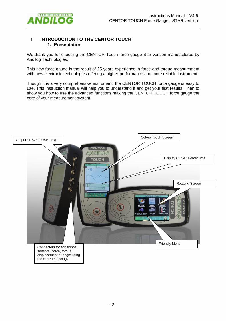
We thank you for choosing the CENTOR Touch force gauge Star version manufactured by Andilog Technologies. This new force gauge is the result of 25 years experience in force and torque measurement with new electronic technologies offering a higher-performance and more reliable instrument. Though it is a very comprehensive instrument, the CENTOR TOUCH force gauge is easy to use. This instruction manual will help you to understand it and get your first results. Then to show you how to use the advanced functions making the CENTOR TOUCH force gauge the core of your measurement system.
Output : RS232, USB, TOR Colors Touch Screen
Display Curve : Force/Time
Connectors for additionnal sensors : force, torque, displacement or angle using the SPIP technology
Rotating Screen
Friendly Menu

Instructions Manual – V4.6 CENTOR TOUCH Force Gauge - STAR version
- 4 -
2. Definition
a. Internal Channel Called also: Channel V1 or internal sensor.
b. External Channel c. Calibration
II. HANDLING
CAUTION: Unpacking. Check the CENTOR TOUCH force gauge has been supplied in its carrying case and that it has not been damaged during transportation. If in doubt, contact ANDILOG TECHNOLOGIES to obtain basic checks to ensure that the gauge has not been damaged.
1. Unpacking The CENTOR TOUCH force gauge is supplied with:
Carrying case
Extension rod (Internal sensor only)
Hook (Internal sensor only)
Compression plate (Internal sensor only)
Power adaptor
Certificate of calibration
2. Recommendation before first use a. Battery
The battery reaches its maximum capacity after several charges. This is very important! A new force gauge has a battery that does not have its full capacity at the first power on. The force gauge will shut down automatically if the battery is too low. The battery life is 8 hours of normal use. The gauge should be charged after normal use. If it is not used for a long time, you should charge it every 3 weeks. This to assure maximum life for the batteries. It is recommended to use the original power adaptor supplied by ANDILOG Technologies. The power adaptor has the following specifications: 12V , 1.5A
b. Sensor
Never connect accessories (hook, plate, . . .) directly to the sensor rod. Use the extension rod delivered with your instrument . In spite of its mechanical protection, sensor overload can damage the instrument. The instrument stops if the capacity has been exceeded 10 times. You have to return it to ANDILOG TECHNOLOGIES for checking. It is important that measured values are under 90% of the sensor capacity.
c. Test Stand The gauge can be affixed to a test stand via two M5 screws, which should not extend through the back cover more than 3 mm. Please contact ANDILOG Technologies if you need more information or if you need a fixture to mount your force gauge to a test stand.

Instructions Manual – V4.6 CENTOR TOUCH Force Gauge - STAR version
- 5 -
d. Conditions
Working Temperature: 0°C to +35°C
Stock Temperature: -20°C to +45°C
Humidity: 5% to 95%
Altitude: 3000m
e. Warranty
3. Starting your force gauge
Press the ON/OFF button, the information screen showing the status of the CENTOR TOUCH force gauge is displayed for 5 seconds and then the main screen is displayed.
Battery condition: Display the battery condition Date of the day: Display according to the format JJ/DD/AAA or MM/JJ/AAA can be setup in the maintenance menu (see chapter “maintenance”) . Software version: the line indicates the software verion installed on the force gauge Internal and External sensor: show the type of attached sensor (force, torque, deflection or angle) and its condition.
A red X indicates that the sensor is not recognized or has a serious problem.
A red exclaimation point ! indicates the sensor has a problem that is not serious: An
overload or calibration time past.
Battery condition
Internal sensor
External sensor
Date of the day Sensor Information
Software vesrion
Instructions Manual – V4.6 CENTOR TOUCH Force Gauge - STAR version
- 6 -
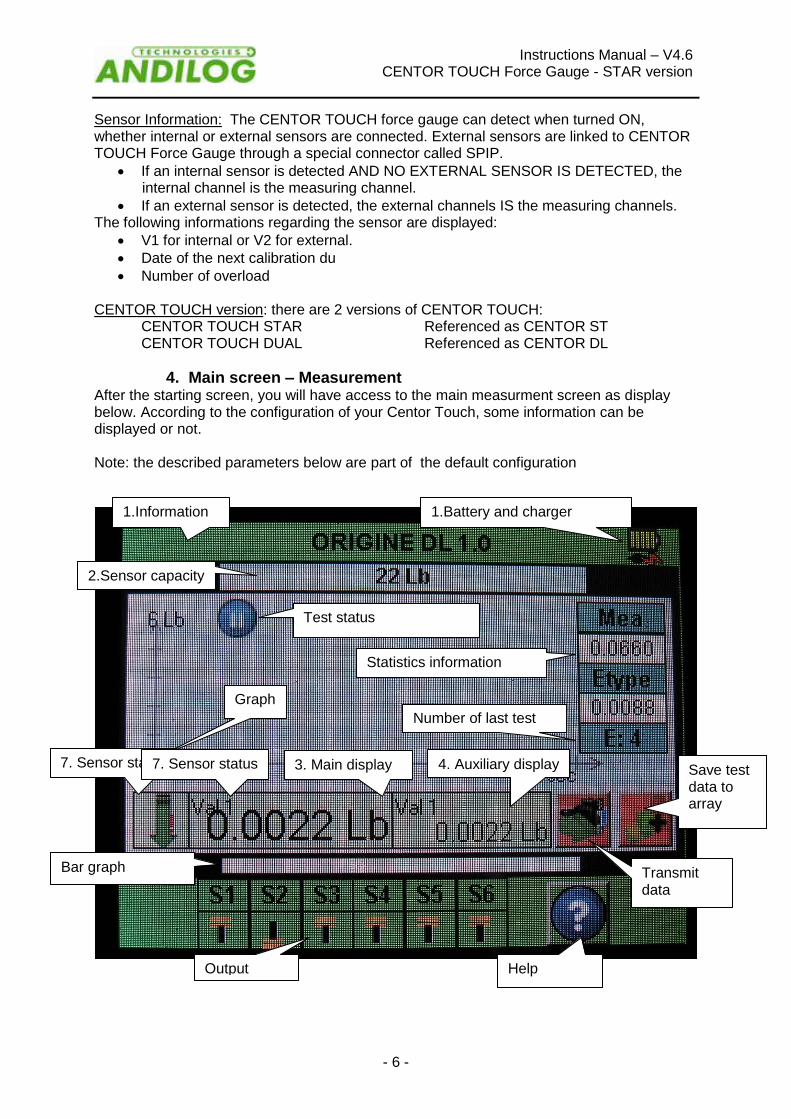
Sensor Information: The CENTOR TOUCH force gauge can detect when turned ON, whether internal or external sensors are connected. External sensors are linked to CENTOR TOUCH Force Gauge through a special connector called SPIP.
If an internal sensor is detected AND NO EXTERNAL SENSOR IS DETECTED, the internal channel is the measuring channel.
If an external sensor is detected, the external channels IS the measuring channels. The following informations regarding the sensor are displayed:
V1 for internal or V2 for external.
Date of the next calibration du
Number of overload CENTOR TOUCH version: there are 2 versions of CENTOR TOUCH: CENTOR TOUCH STAR Referenced as CENTOR ST CENTOR TOUCH DUAL Referenced as CENTOR DL
4. Main screen – Measurement After the starting screen, you will have access to the main measurment screen as display below. According to the configuration of your Centor Touch, some information can be displayed or not. Note: the described parameters below are part of the default configuration
1.Information bar
1.Battery and charger information
Bar graph
2.Sensor capacity
Test status
Graph
Statistics information
Number of last test saved
3. Main display 4. Auxiliary display Save test data to array
Output status
Help
Transmit data
7. Sensor status 7. Sensor status

Instructions Manual – V4.6 CENTOR TOUCH Force Gauge - STAR version
- 7 -
When the battery is low, a low battery message is displayed on the screen as the gauge is turned on, before carrying out tests. If the charger is connected, the message « CHARG » will be displayed. While displaying low battery indication, CENTOR TOUCH force gauge runs internal tests. If during these tests, problems are detected, the internal information screen is displayed. An error message indicates that the force gauge is not in optimum operating condition for measuring. Please see the Appendice chapter for the meaning of indications and error messages. If the error detected makes measurement impossible (defective sensor for example), the display will hold and it will be impossible to take any further action. Then return the instrument to ANDILOG TECHNOLOGIES for examination. If the error detected does not make measurement impossible (low battery for example) you can switch to the main screen by pressing MAX button.
5. Display Mode NOTE: Described here are manufacturer settings, prepared by ANDILOG TECHNOLOGIES for delivery.
When turned on, CENTOR TOUCH force gauge displays a greeting screen. After a short period of tome the gauge status screen is displayed. Sensor Capacity: the range of the sensor detected can be displayed at any time, even for additional external sensor.
GRAPH SETUP MAIN DISPLAY
SETUP
BASIC DISPLAY SETUP
STATISTICS SETUP
COMMUNICATION SETUP
MAINTENANCE SETUP

Instructions Manual – V4.6 CENTOR TOUCH Force Gauge - STAR version
- 8 -
6. Main display: Many vaues can be displayed in this window. See setup screen for details. Bar graph: A black line is the representation of the applied force. If the bar graph is full, it means that the sensors maximum range is reached: risk of overload! Auxillary display: Many vaues can be displayed in this window. See setup screen for details. Information bar: Low battery indication: pictogram indicating the battery power status via 4 horizontal lines which respectively symbolize 25%, 50%, 75% and 100% of power. Sensor status: An easy-to-remember small symbol indicates the direction of the force exerted on the sensor
Information bar
Battery and charger information
Bar graph
Sensor information
Test status
Graph
Statistics information
Number of last test saved
Main display Auxiliary display Save test data to array
Output status
Help
Transmit data
Sensor status
Type of data
Instructions Manual – V4.6 CENTOR TOUCH Force Gauge - STAR version
- 9 -
The name of the data displayed in the main and auxiliary displays is shown in the upper left of each display.. We will see on Chapter 4 part C how to change the displayed value. Zero or tare Touch the maind display window zero or tare force gauge. This action tares the gauge. The gauge will take into consideration the weight of accessories (hook or plate) fixed on the sensor’s rod. Taking this action resets all memories and peak values. NOTE: When turned ON the CENTOR TOUCH completes several self-tests to check the sensor’s health. It is possible to leave tools fixed on the force gauge, but the total weight must not exceed 10% of the sensor’s maximum capacity. Measure unit The units are displayed in the main and auxiliary display windows. We will see on Chapter 4 part C how to change the displayed units Backlight When using the force gauge, the backlight automatically turns off after a preset time of operation. The total battery life the CENTOR TOUCH will be reduced when the backlight is turned on.
7. Advanced functions
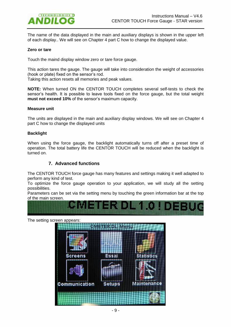
The CENTOR TOUCH force gauge has many features and settings making it well adapted to perform any kind of test. To optimize the force gauge operation to your application, we will study all the setting possibilities. Parameters can be set via the setting menu by touching the green information bar at the top of the main screen.
The setting screen appears:

Instructions Manual – V4.6 CENTOR TOUCH Force Gauge - STAR version
- 10 -
Screens Change displayed test results Graph Activate and change graph display parameters Statistics Activate and select values for statistical analysis. Communication Select and activate communications. Setups Basic steups Maintenance Diagnostics
Instructions Manual – V4.6 CENTOR TOUCH Force Gauge - STAR version
- 11 -
III. START your measurements
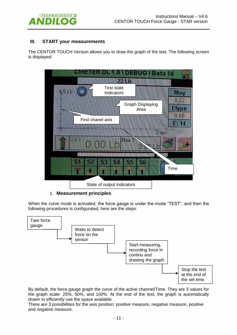
The CENTOR TOUCH Version allows you to draw the graph of the test. The following screen is displayed:
1. Measurement principles
When the curve mode is activated, the force gauge is under the mode “TEST”, and then the following procedures is configurated, here are the steps: By default, the force gauge graph the curve of the active channel/Time. They are 3 values for the graph scale: 25%, 50%, and 100%. At the end of the test, the graph is automatically drawn to efficiently use the space available. There are 3 possibilities for the axis position: positive measure, negative measure, positive and negative measure.
State of output indicators
Graph Displaying Area
First chanel axis
Time
Tare force gauge
Waits to detect force on the sensor
Start measuring, recording force in continu and drawing the graph
Stop the test at the end of the set time.
Test state Indicators

Instructions Manual – V4.6 CENTOR TOUCH Force Gauge - STAR version
- 12 -
2. States Indicators On the left corner of the main screen, the state indicator is displayed:
Stand-by mode. Waiting for a start event.
Acquisition mode. Aquiring data.
Test complete. To start a new test tare the force gauge. If you would like to stop the test before the end of the time, press the state indicator.
3. Graph displaying area To start measuring and drawing the graph, you must touch the main display area to do the tare. When the CENTOR TOUCH detects force on the sensor, it will start measuring force & drawing the graph. While applying a force to the gauge, the graph is drawn on the screen and the current and maximum values are displayed according to the setup in the SCREENS settings. The CENTOR TOUCH data capture rate is 5,000Hz, however, for better readability, it displays a maximum of 1000 points for a graph. If you wish to acquire a more precise graph, you can transfer the data in continu to a computer using :
The RS232 output allowing a maximun acquisition rate of 100 values per second
The USB outputs allowing a maximum acquisition rate of 1000 values per second
The state indicator changes from to . To stop the graph acquisition, touch the graph area . However, the acquisition automatically stops after the selected time in the graph setup screen. The test length can be set, see Chapter “Graph and test settings”.
At the end of the acquisition the state indicator changes to . At this step, you can:
Read the graph
Read calculated values during the test by touching the statistics window.
Download calculated values or the graph on a PC through the RS232 output (using the send data key “”)
Enter the CONFIGURATION mode and modify the configuration
Erase the graph by touching the graph display area” To start a new test or change to display mode, you have to erase the graph by touching the graph display area or taring the gauge by touching the main display window.
Instructions Manual – V4.6 CENTOR TOUCH Force Gauge - STAR version
- 13 -
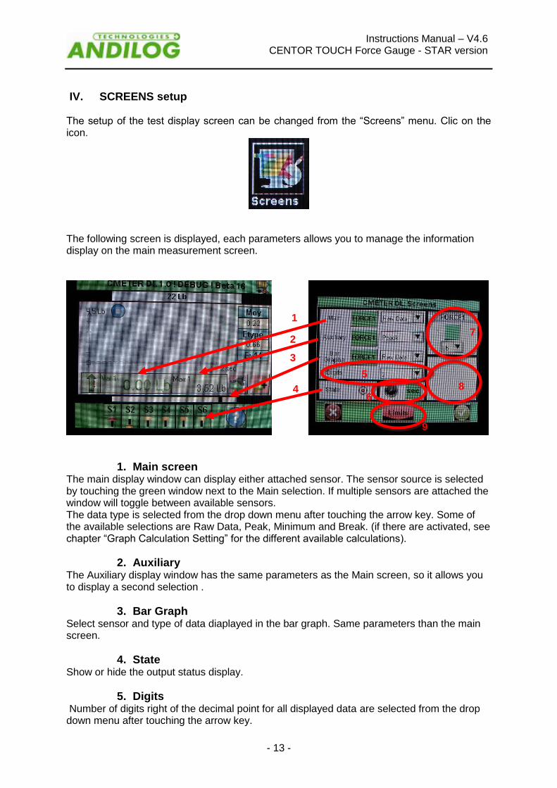
IV. SCREENS setup The setup of the test display screen can be changed from the “Screens” menu. Clic on the icon.
The following screen is displayed, each parameters allows you to manage the information display on the main measurement screen.
1. Main screen
The main display window can display either attached sensor. The sensor source is selected by touching the green window next to the Main selection. If multiple sensors are attached the window will toggle between available sensors. The data type is selected from the drop down menu after touching the arrow key. Some of the available selections are Raw Data, Peak, Minimum and Break. (if there are activated, see chapter “Graph Calculation Setting” for the different available calculations).
2. Auxiliary The Auxiliary display window has the same parameters as the Main screen, so it allows you to display a second selection .
3. Bar Graph Select sensor and type of data diaplayed in the bar graph. Same parameters than the main screen.
4. State Show or hide the output status display.
5. Digits Number of digits right of the decimal point for all displayed data are selected from the drop down menu after touching the arrow key.
1
2
9
3
4
7
8
5
6
Instructions Manual – V4.6 CENTOR TOUCH Force Gauge - STAR version
- 14 -
6. Timer Selection Touching the key next to the clock symbol will change the test timer from milliseconds to seconds then minutes.
7. Sensor Units V1 Sensor units are independently selected. Touch the arrow key in the desired display window to display all available units. The units allowed will change with the sensor attached. Force, torque or travel units. The green key above the units selection determines the sign of the displayes value, either: +, - or no sign can be selected.
8. Sensor Units V2 Same as Sensor Unit V1
9. Limits Allows you to access to the limites setting screen, see the chapter “Limits”
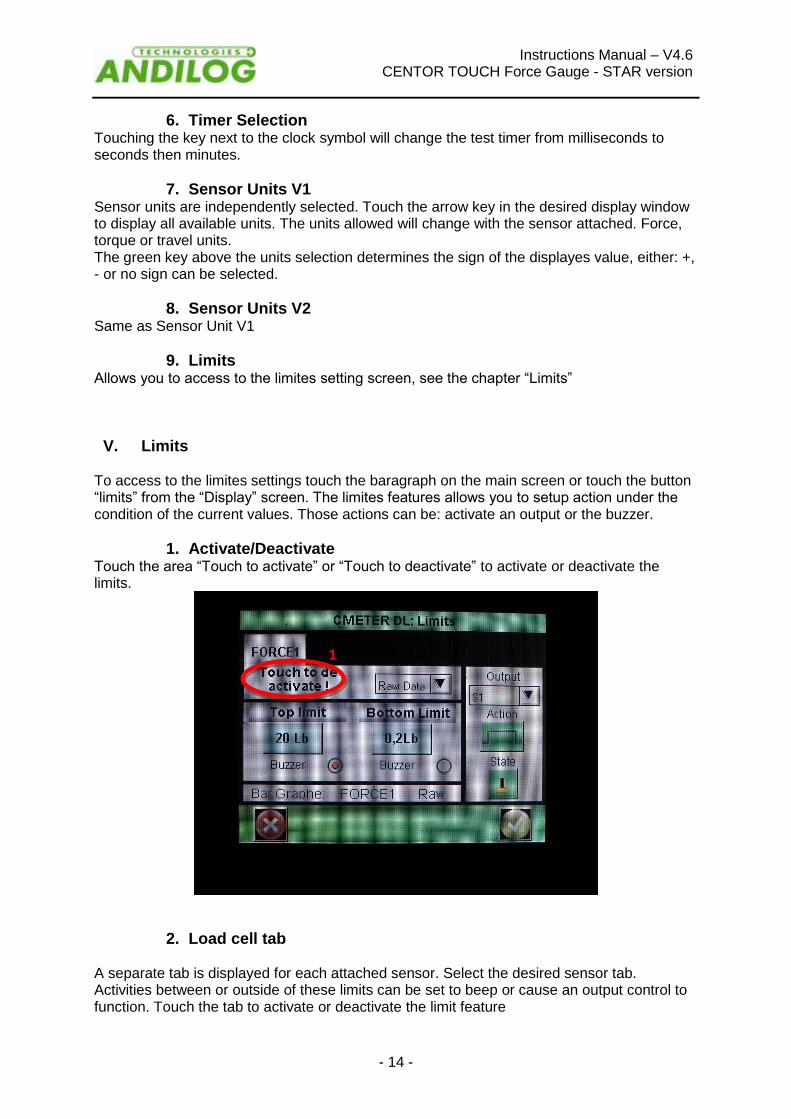
V. Limits To access to the limites settings touch the baragraph on the main screen or touch the button “limits” from the “Display” screen. The limites features allows you to setup action under the condition of the current values. Those actions can be: activate an output or the buzzer.
1. Activate/Deactivate Touch the area “Touch to activate” or “Touch to deactivate” to activate or deactivate the limits.
2. Load cell tab
A separate tab is displayed for each attached sensor. Select the desired sensor tab. Activities between or outside of these limits can be set to beep or cause an output control to function. Touch the tab to activate or deactivate the limit feature
1
Instructions Manual – V4.6 CENTOR TOUCH Force Gauge - STAR version
- 15 -
3. Data Type Select the data applied to the limit. Touch the arrow to select the data. Ganarally, the current value is used but you can setup a limit on the maximun or a calculation (mean, standard deviation, break,... see chapter “Graph calculation settings”).
4. Top and Bottom limits
You can setup a top and a bottom limits for each channel by touching the button and enter the limit value from the diplayed keyboard. Then you can select “buzzer” if desired for each limit. The buzzer will sound if the data applied to the limit falls outside the limit. The limits values will be automatically displayed on the bargraph on the main measure screen. During the test, the current reading will change of colors when a limit is reached.
5. Activate an Output
The limit can control an output action. Select the desired output or none. The output action is chosen by setting the desired output in the output control. Set the action and state as required. Operations:
If the bottom limit is the only one configurate, the state of the output will change when the measured value will exceed the limit value.
If the bottom and the top limit are configurated, the state of the output will change when the measured value will be in between of the limit values
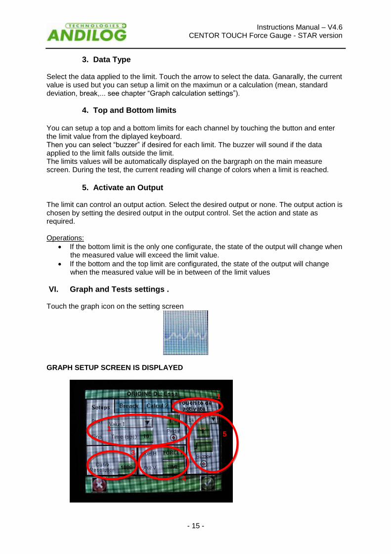
VI. Graph and Tests settings . Touch the graph icon on the setting screen
GRAPH SETUP SCREEN IS DISPLAYED
1
1
3
4
5

Instructions Manual – V4.6 CENTOR TOUCH Force Gauge - STAR version
- 16 -
1. Setups tab. Touch the control in the upper left corner to activate or deactivate the graph.
2. Tests settings There is 2 parameters that need to be defined to set the test
The start condition of the test
The length of time to run the test
a. Start settings of the test Once the force gauge is tared, the Centor Touch is waiting an event to start the acquisition. There are three type of possible events:
Force value on the load cell
External event, by example: Input on the force gauge, foot pedale,...
Trigger Choose the start condition in the roll menu (“Value 1” for the internal load cell or “Value 2” for the external load cell, “Trigger” for the external event) or clic on the red dots below “Pedal”. If you choosed “Value” 1 or “Value 2”, you have to define the percentage of the load cell capacity that start the acquisition. Example: the load cell is 100 Newton maximum, the test graph will start when the force reaches 1% of 100 Newton or 1 N. Touching the percent sign gains access to the adjustment keypad.
b. End of the test Select the length of time to run the test. This run time has an influence on the curve resolution. Example: if you running time is 10 secondes and the resolution of the curve is 1000, so you will record a point every 0.01 seconde. Touch the control to activate the keypad. Enter desired test time.
Note: A test can be stopped before the end of the running time by touching the icon or using an Input from the force gauge. See “ Chapter X – Input & Output”. However this stop before the end of the test will have no effects on the curve resolution and less points will be recorded. Example: if you running time is 10 secondes and the resolution of the curve is 1000, so you will record a point every 0.01 seconde. If the test is stopped after 5 secondes, the acquisition will recorde 500 points and the resolution will still be equal to 10ms.
c. Curve Resolution The graph display resolution is adjustable from 1 to 1000 points, by default it is set to the maximun at 1000.
d. Axe H & Axe V Horizontal and vertical display data can be changed by touching the name of the axis. You can choose to display: the time, Internal channel (Force 1), External channel. So you can display the force / time, or also torque / angle, or torque / force...
e. Output control Graph completion can cause an output control to change. Select the output control from the drop down menu then select control action and state.You can select two type of actions:

Instructions Manual – V4.6 CENTOR TOUCH Force Gauge - STAR version
- 17 -
Beep: Toggle the buzzer control to enable the buzzer for the output condition if desired
Active an Output of the force gauge: choose the output to activate (from 1 to 6) and its running mode: pulse or switch mode and the high or low state. More details on the input/output, see “Chapter X – Input & Output”.
VII. Graph Calculation settings The Force gauge Centor Touch allows you to setup automatic calculations derived from the graph. The settings of the calculation can be done in the Test menu. It is possible to perform simultaneous 2 calculations in addtion of the current value, the maximun and the minimun.
1. Calculation The Centor Touch allows you to select 2 calculs, derived from the graph. Select the Calcul 1 or 2 tab. The Test running mode should be activated to perform calculation.
The following calculations are availables: Average: The average of force or torque readings over selecter time or travel. Select time or travel parameters after selecting average. Breack: The calculated break point. Select the percent of peak to determine break point after selecting breack. C. Derive – Calculates the derivative value of the curve on a selected period of time. Allows you to determine the slope (gradient) C. Porte – Allows you to calculate the maximun force when the force is greater than a limit and for a defined period of time after the limite. This calculation is used for the check of automatic doors. First Pic – Selects the first peak in multiple peak graph. Select the percent of peak to determine peak point after selecting First Pic. Force contact – Calculates the maximun force when your closing a contact or a switch plug on the Input E1 (by example a foot pedale). Inst. Max – Calculates at which periode of the test, the maximun force occured. NiveauN – Calculates the value of a channel, when the other one reached its defined limites Peak – The maximum force or torque measured during the test. Sleeping mean – Moving average
1 2

Instructions Manual – V4.6 CENTOR TOUCH Force Gauge - STAR version
- 18 -
Traduire Force_T. – Force at a specific time. Select time in milliseconds.
2. Output actions
After each calculation, it is possible to activate an output of the force gauge. Select the output control from the drop down menu to activate (from 1 to 6) then select its running mode: pulse or switch mode and the high or low state. More details on the input/output, see “Chapter X – Input & Output”. Thoses actions can be very usefull whent you want communicate with the test stand. Example: stop the test stand when the force gauge detectes the force breack.
VIII. Record datas and Statistics mode. The Centor Touch has a memory of the last 100 values and automatically calculating the mean, the standad deviation and the mean divided by the standard deviation.It is possible to record 3 results simultaneously to choose from the maximun, the minimun, calcultaion1 and calcultion2. Note: The force gauge can’t record multiples curves. Only the last curve is stored. You have to connect the force gauge to a computer or used the memory card DATASTICK to save multples curves. Statistcs must be enabled by touching the statistics symbol on the setup screen.
1. Statistics setup
Select the desired result to be enterd into the statistic arrays, you can choose 3 types of values to record: maximun, minimun, calculation1 or calculation2 for each channel. Select the units desired.
3
1
2

Instructions Manual – V4.6 CENTOR TOUCH Force Gauge - STAR version
- 19 -
More than one result can be averaged to create a saved result. Enter this number in the Samples. Then you would be able to display the tab of values by touching button “Arays”.
2. Records datas After a test is complete the test results must be saved to the statistics array. To save the results touch the save results symbol.
Once values are saved, the mean is udpated and display in the first preview results tab..
To view all the calculation and the statistical results touch the mean window. You can then transfer those results to a computer. See the Chapter “Communication Setup”
.

Instructions Manual – V4.6 CENTOR TOUCH Force Gauge - STAR version
- 20 -
IX. Communication setup. It is poosible to connect your Centor Touch to a computer or to a system including a RS232, USB or Analog input. Select the communication setup by touching the communication symbol.
Note: One and only one of the three choices for data output is available at one time. Select the tab for either RS232, ANALOG or USB. The CENTOR TOUCH has four types of outputs:
RS232
USB
Analog
Datastick – USB Stick (optional)
1. RS232 or Serial commands Input/Output of the RS232 can be set for continuous or on demand:

Instructions Manual – V4.6 CENTOR TOUCH Force Gauge - STAR version
- 21 -
Continuous: Data can be sent continuously using the serial command, with a frequency rate around 100Hz.
Demand: A request from the force gauge has to be set to send data. This request can be setup from the computer using ASCII parameters using the serial commands (see the list below), using the input E1 or E2 from the force gauges, or data can also be sent by touching the send data symbol on the main panel.
Make the appropriate selection from the send drop down menu. Set speed, parity, stop bits and number of bits to match the connected computer. By default values are:
Speed: 9600
Parity: None
Stop: 1
Bits: 8 Here are the serial commands (Using our dedicated software R-SIC or ASCII parameters):
F: Current value
P: Maximun value
V: Minimum value
C: Calculation
T: Last 100 calculated values
W: Last Graph
Z: Tare the force gauge The following rules applied to the communication protocols on “Demand” mode:
The force gauge doesn’t send trailling carateres
The force gauge sent the sign +,- or none according to the measured values and the settings.
The resolution of the sent values depends of the load cell capacity
The force and displacement values are separated by a TAB charatere (09 decimal and 09 hexadecimal
The force gauge sent the data “?” if the request isn’t valid
The force gauge sent the data “!” if the value is empty

Instructions Manual – V4.6 CENTOR TOUCH Force Gauge - STAR version
- 22 -
2. USB Connection The USB is set as the RS232 communication: on demand or conitun mode; and commands are similar. However you can:
Set the the baud rate value in continuous mode if “Eco” is selected in the menu “Setup”
The Baud rate is fixed to 921600
3. Analog Connection The Centor Touch is able to send analog data at a rate of 100Hz. The analog output is +1/-1V. Analog output is done throught the pin 10 of the 26 pins connector.

Instructions Manual – V4.6 CENTOR TOUCH Force Gauge - STAR version
- 23 -
4. DATASTICK – USB Memory Stick (optional) a. Presentation
The DATASTICK kit is an option available with the CENTOR TOUCH, in order to save your data on a USB memory stick. The kit includes: a USB Stick and a connexion cable (to link the CETOR TOUCH through the 26 pins connector to the USB stick). This feature is available for all CENTOR TOUCH from version V4.6
b. Configuration You can activate and configure the Datastick communication setting from the Menu “communication”
The CENTOR TOUCH is able to save several types of data on the USB stick, to choose from:
Calculated values:max, min, and calculations selected in the menu “TEST”
Current value: the value measured by the sensor at the time of communication.
Curve:save the curve plotted on the screen
Curve and calculations: the plotted curve + max, min, and calculations selected in the menu “TEST”
Statistics:datas saved in the statics table of the CENTOR TOUCH
You can change the default file name for the unitary datas (statistics and values). Default file name: “ANDILOG_date” (ie: ANDILOG_20130107.txt”). Push the button to change the name. Datas will be recorded at the end of this file. The directory where the curve is saved is by default names “DATASTICK_date_hours”. You can change this default name by pushing the button. The directory includes 2 files:
Data.txt: curve datas
testSettings.txt: setting of the curve
All those files are saved as TXT format, and so can be open with regular Table software as Microsoft Excel. Datas are separated by a TAB character (09 decimal and 09 hexadecimal) and the rows are separated by a carriage return (decimal 13, hex 0D).

Instructions Manual – V4.6 CENTOR TOUCH Force Gauge - STAR version
- 24 -
c. Save your data Once the DATASTICK communication is active, a USB icom appears on the main Measure screen:
Save you data on the USB by pushingon the icon:
During the data transfer, the USB icon becomes a timer; do not disconnect the USB stick at this time. Once the timer disappears you can disconnect the USB stick.
d. Use multiples USB stick The USB stick supplied by ANDILOG at the time of the purchase of the DATASTICK option, has been set to communicate with your CENTOR TOUCH; and it recognize the serial number of your CENTOR TOUCH. However you can duplicate this USB stick as many as you want. To do so: copy and paste the file “datastick config” (saved on the original USB stick) on your own USB stick.
X. Input & Output and Foot Pedal
The Centor Touch is able to communicate and supplied information with an external system such as a test stand, using its inputs and outputs. The Centor Touch has:
3 Inputs (Pedal, E1 and E2)
6 Outputs (S1 to S6) Each Input/Output can be setuped separtly using various menu and features of the Centor Touch (limits, calculation, communication...). But a menu dedicate to setup the state and action of those Input/Output is available from the third panel “E/S Tor” from the Maintenace menu.

Instructions Manual – V4.6 CENTOR TOUCH Force Gauge - STAR version
- 25 -
1. Outputs Each output from 1 through 6 can be setupet separtly. Those outputs can change state under different conditions depending of the settings of the force gauge. The main states are:
Nothing: no action
Calcul 1: changes state at the end of calculation 1
Calcul 2: changes state at the end of calculation 2
Test End: changes state at the end of the test
Limite: changes state after reaching a limite (channel 1 or channel 2)
Over 120%: changes state when the measured value is over 20% of the maximum capacity of the load cell. It is used to protect the load cell when mounted on a test stand.
For each output, it is possible to define its default value (at the beginning of the test): high or low :
Low Level High Level Also it is possible to define the type of actions:
Switch (steady): the output changes state and stay in this new state until the end of the test or until the condition is true (limits case)
Pulse: the output changes state for a period of time of 50ms, then come back to its previous state.
2. Inputs and Pedal The 3 input (Pedal, E1 and E2) of the Centor Touch can be setuped separtly. Those Inputs allow you to do the following actions:
Active Test: start the test
End Test: Stop the test
Tare Vx: tare the channel Vx
F Contact: uses during the calculation
Instructions Manual – V4.6 CENTOR TOUCH Force Gauge - STAR version
- 26 -
For each input, it is possible to define its default value (at the beginning of the test): high or low :
Low Level High Level The Centor Touch can be connected to an external pedal switch, it is in this menu that the parameters and action af the pedal can be done.
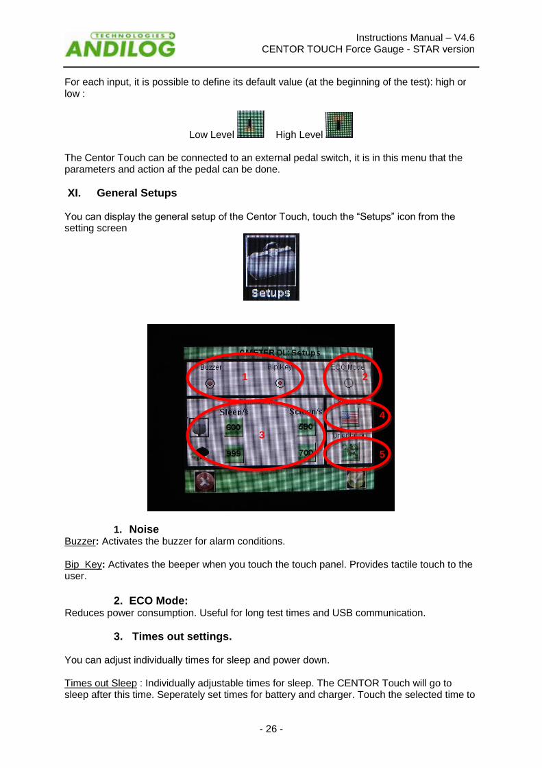
XI. General Setups You can display the general setup of the Centor Touch, touch the “Setups” icon from the setting screen
1. Noise Buzzer: Activates the buzzer for alarm conditions. Bip Key: Activates the beeper when you touch the touch panel. Provides tactile touch to the user.
2. ECO Mode:
Reduces power consumption. Useful for long test times and USB communication.
3. Times out settings. You can adjust individually times for sleep and power down. Times out Sleep : Individually adjustable times for sleep. The CENTOR Touch will go to sleep after this time. Seperately set times for battery and charger. Touch the selected time to
1 2
3
4
5

Instructions Manual – V4.6 CENTOR TOUCH Force Gauge - STAR version
- 27 -
display keypad. Erase then enter new time in seconds then touch the check key on the keypad. Times out Screen: Individualy adjustable times for display back light power down. Seperately set times for battery and charger. Touch the selected time to display keypad. Erase then enter new time in seconds then touch the check key on the keypad.
4. Orientation
The CENTOR Touch diaply can be rotated in 90 degree increments. Touch the running man picture to select orientation.
5. Language.
Touch the language picture to select desired display language. Touch the check key to exit and save settings or the “x” key to exit with no save.
XII. Maintenance panel The maintenance panel allows access to basic test and control functions. Select the maintenance symbol from the setup panel
1. General The Setup tab give you the load cell information, the software version, the state of the batterie and the possibility to adjust hours and date. Auto Test: Launches an auto test and display the health details of all sensors connected and battery conditions Color: Display color capabilities of the display. Touch pad: Allows calibration of the touch pad.
Touch to set date & time

Instructions Manual – V4.6 CENTOR TOUCH Force Gauge - STAR version
- 28 -
2. Settin the clock: Date and time are set from the maintenance Setups tab. Touch the date format control. Access is granted to the date and time panel.
Change date and time but touching the appropriate up or down arrows. Select Am or PM. You can also chose the clock format:
EU = day; month: year.
US = month; day; year. Touch the check arrow to save changes and exit or the x to forget changes and exit.
3. Chanels tab Display the details of the sensor memory data and the present settings of all input and output signals.
4. E/S Tor The ES/TOR tab allows access to all input and output controls. All can be changed from this panel. See the chapter “Input & Output and Foot Pedal” for more information.

Instructions Manual – V4.6 CENTOR TOUCH Force Gauge - STAR version
- 29 -
XIII. ASSOCIATED PRODUCTS
1. CENTOR TOUCH family There are several types of CENTOR TOUCH force gauges with increasing capabilities according to the chosen version. CENTOR TOUCH Star: first graphic type with numerous additional calculation functions and capability to read and recognize numerous external sensors. CENTOR TOUCH Dual: is the most sophisticated force gauge model with CENTOR TOUCH easy and CENTOR TOUCH DUAL functions. Plus the capability of simultaneously reading two sensors (force + force; force + torque, force + displacement; torque + angle; ect.). NOTE: Whatever the CENTOR TOUCH force gauge model, it is may possible to modify the force gauge type. If you wish update your CENTOR TOUCH force gauge, please contact your ANDILOG TECHNOLOGIES dealer. If you want more information about the CENTOR TOUCH family, please contact your ANDILOG TECHNOLOGIES dealer or visit our web site: WWW.ANDILOG.COM
2. Modules for external sensors One of CENTOR TOUCH force gauges has the capability of reading any type of force sensor. Thus an external sensor with a different capacity can be used with CENTOR TOUCH force gauge without buying a new force gauge. ANDILOG TECHNOLOGIES uses a special cable for this. This cable links the external sensor and the force gauge. It is equipped with a connector or module called ‘SPIP’. ‘SPIP’ module is a tiny case containing the definition and calibration settings of sensor. When SPIP is connected to the force gauge, the internal sensor (if there is one) is disconnected and the force gauge takes into consideration the information from the new sensor and displays data from this sensor. Disconnecting the ‘SPIP’ makes the internal sensor active again. In some applications (i.e. force sensors), where is no internal sensor available, CENTOR TOUCH force gauge only uses external sensors equipped with SPIPs. Another exceptional feature of this type of electronic instrument (sampling rate of 1000 Hz, autonomous, integrated calculation and thresholds) is the ability, thanks to SPIP module, to read not only force and torque sensors, but also to read values from linear displacement sensor (analog or incremental sensors), rotational displacement sensor (analog or incremental sensors), pressure sensor, etc…. Thanks to the SPIP module, CENTOR TOUCH can read the type of sensor connected and chooses appropriate unit choices. If you want to connect your CENTOR TOUCH to another sensor, contact your ANDILOG TECHNOLOGIES dealer.

Instructions Manual – V4.6 CENTOR TOUCH Force Gauge - STAR version
- 30 -
3. Manual or motorised test stands To ensure a precise measurement, it is important that CENTOR TOUCH force gauge is placed in the axis of the force throughout the test. To ensure this placement is correct, ANDILOG and ANDILOG TECHNOLOGIES have developed a complete range of simple and sophisticated test stands. These are manual or motorised test stands, some of them being computer-controlled. If you want more information about test stands, contact your ANDILOG TECHNOLOGIES dealer or visit our web site www.com-ten.com.
4. Gripping accessories ANDILOG TECHNOLOGIES offers a series of gripping accessories adapted to different tests: hooks, plates, pliers, self-squeezing jaws, eccentric jaws, peeling fixture, etc… If you want to receive our catalogue, contact your ANDILOG TECHNOLOGIES dealer.
5. Acquisition software ANDILOG TECHNOLOGIES has developed several programs to save and analyse values. You want to analyse values on a chart: RSIC software has been developed to this. You want to capture the values graph and use graphics tools: CALIGRAF software goes further in tests analysis. If you wish to connect your CENTOR TOUCH force gauge to a PC via one of our programs, contact your ANDILOG TECHNOLOGIES dealer.
6. Interface Cables
Several interface cables can be used with CENTOR TOUCH force gauge: External pedal: allows simulation of a keyboard button Cable for external contact: allows force calculation from closing /opening of contact (equipped with male-female plugs): Linking cable for motorised test stand STENTOR, allows to stop the stand according to a condition defined by CENTOR TOUCH force gauge: Cable for analog link (with male-female plugs): links your gauge to another system Cable for Digimatic link: connect your gauge to a statistical printer Cable for RS232 link: connect your gauge to a computer using the RS232 output Multifunction cable test stand STENTOR control and RS232 link

Instructions Manual – V4.6 CENTOR TOUCH Force Gauge - STAR version
- 31 -
XIV. APPENDICES
1. Function Chart
The different CENTOR TOUCH versions offer different functions, here is the function chart according to the different force gauge version.
FUNCTIONS AVAILABLE STAR DUAL
Resolution 1/1000 X X
Accuracy 0.1% X X
Data Capture Rate 4000 Hz X X
Bar graph display X X
Display of Torque/Time – Force/Time curve X X
Display settings X X
Display inversion X X
Capacities: 5 / 10 / 25 / 50 / 100 / 250 / 500 / 1000 N X X
Possibility to use external sensor (fixed connection) X X
Possibility to read different sensors X X
Reading of incremental sensors X X
Simultaneous reading of two sensors X
Display of 2 sensors graph F (X) X
Overload alarm X X
Simultaneous display of current and peak values X X
Selection of the unit of measure X X
Can be used with a pedal X X
Limits settings X X
Limits action on an external contact X X
Motorised test stand control on limit X X
RS232 output settings X X
Bi-directional RS232 output X X
Analogue output X X
Digimatic output X X
Calculations X X
Breaking point value X X
First peak values X X
Force / Torque value at T time X X
Average peak value X X
Derived Torque / Force value X X
Torque / Force value at the opening of contact X X
Motorised test stand control after calculation X X
Graph Memory X X
Last 100 calculated values memory X X
Compatible with RSIC X X
Auto power off X X
Battery life 8 hours in normal use X X
Non volatile settings memory X X
Factory settings memory X X
Customer settings memory X X
Restore for setting X X
Low battery indication X X
Recall of last calibration date X X
Backlit screen X X
Metal case X X

Instructions Manual – V4.6 CENTOR TOUCH Force Gauge - STAR version
- 32 -
Rubberised shock-proof protection X X
Splash-proof X X
Industrial oils resistance X X
Drop-proof to 1 m (without accessories) X X
Fixing through threaded holes / metric thread X X
Supplied in carrying case with accessories and power adaptor X X
Supplied with calibration certificate X X
English or French instruction manual (customer preference) X X
Manufactured in France X X
2 year warranty (except for sensor overload) X X

Instructions Manual – V4.6 CENTOR TOUCH Force Gauge - STAR version
- 33 -
2. Errors Messages Information screen:
This screen is displayed after completion of internal tests and a minor or major defect has been found.
Minor defects:
Low battery
Number of overloads less than 5
Expired calibration date Touch Measure to continue.
Major defects:
Damaged sensor
High number of overloads (>5)
Internal error
Sensor not attached

Instructions Manual – V4.6 CENTOR TOUCH Force Gauge - STAR version
- 34 -
3. Factory Settings Screens default
Graph default

Instructions Manual – V4.6 CENTOR TOUCH Force Gauge - STAR version
- 35 -
Statistics default
Communications default

Instructions Manual – V4.6 CENTOR TOUCH Force Gauge - STAR version
- 36 -
Setups default
Maintenance default

Instructions Manual – V4.6 CENTOR TOUCH Force Gauge - STAR version
- 37 -
4. Connections Connector detail SubDHD 26 pins connected to CENTOR TOUCH electronic card PIN 1 GND 2 E1 input 3 Digimatic Ready
4 RS232 read data 5 USB device data minus 6 USB host data minus 7 S3 output.
Open collector reguires 50 k ohm pull up to 5 volts DC 8 S2 output
Open collector reguires 50 k ohm pull up to 5 volts DC 9 Gauge reset 10 Analog output 11 E2 input 12 Digimatic request 13 Digimatic clock 14 USB device power 15 USB host power 16 S4 output
Open collector requires 50 k ohm pull up to 5 volts DC. 17 S5 output
Open collector reguires 50 k ohm pull up to 5 volts DC. 18 GND 19 Chassis ground 20 Pedal input 21 Digimatic Data 22 RS232 transmit data 23 USB device data plus 24 USB host data plus 25 S6 output.
Open collector requires 50 k ohm pull up to 5 volts DC. 26 S1 output,
Open collector requires 50 k ohm pull up to 5 volts DC.
Instructions Manual – V4.6 CENTOR TOUCH Force Gauge - STAR version
- 38 -
5. Serial Commands and Control TYPE OF DATA
ASCII
TOUCH SERIAL SETUP RATE CONTROL SETTINGS SET FROM COMMUNICATIONS SCREEN:
110 BAUD
300 BAUD
1200 BAUD
2400 BAUD
4800 BAUD
9600 BAUD RECOMMENDED FOR RS232 COMMUNICATIONS
19200 BAUD
38400 BAUD
57600 BAUD
115200 BAUD RECOMMENDED FOR USB COMMUNICATIONS
230400 BAUD PARITY:
ODD, EVEN OR NONE. STOP BITS
1 OR 2 NUMBER OF BITS
5,6,7 OR 8 CONTROL COMMANDS IF CONTROL SET TO “ON DEMAND” ON THE COMMUNICATIONS SCREEN
Character sent Z force gauge action tare
C calculation D current data & time F force gauge sends current value P maximum value S Stored results T last 100 calculated values U measure units V minimum value W the last graph
All responses from the gauge are not terminated.
The set sign character precedes all responses from the gauge. o +, - or none set in the display screen.
Number of characters sent by the gauge will vary with load cell maximum and decimal position.
Force and travel data separated by horizontal tab character. o 09 decimal, 09 hex and 11 octal.
DATA CONDITIONS IF CONTROL SET TO “CONTINUOUS” ON THE COMMUNICATIONS SCREEN
Force and travel data separated by horizontal tab character. o 09 decimal, 09 hex and 11 octal.
Data line terminated by carriage return character. o 13 decimal, 0D hex and 015 octal.

Instructions Manual – V4.6 CENTOR TOUCH Force Gauge - STAR version
- 39 -
6. Setup Examples Display with graph:
Touch information bar.
Touch graph icon. Set Start to Value 1. 1% End time 10 sec Curve resolution = 10000. Axe H = TIME. Ave V = FORCE1 Send peak data after test complete with send key to the RS232 port:
Touch information bar.
Touch the communications icon. RS232 touch to activate. Set FORCE 1 to peak. Set speed, parity, stopbits and number of bits to match com port on computer. Set Send to key.
After the test is complete touch the send key to transmit data. Start from pedal:
Touch information bar.
Touch maintenance icon. Set pedal control to tare V1

Instructions Manual – V4.6 CENTOR TOUCH Force Gauge - STAR version
- 40 -
7. Dimensions