Operating Manual - American InstrumentOperating Manual Rotational Vacuum Concentrator RVC 2-18...
80
Operating Manual Rotational Vacuum Concentrator RVC 2-18 CD&HCL Part no. 100246 Part no. Ref. Translation of the original operating manual A sb Version 04/2012 Rev. 1.0 RVC 2-18 CD&HCL; ;
Transcript of Operating Manual - American InstrumentOperating Manual Rotational Vacuum Concentrator RVC 2-18...
Operating Manual Rotational Vacuum Concentrator
RVC 2-18 CD&HCL Part no. 100246
Part no. Ref.
Translation of the original operating manual
A sb Version 04/2012 Rev. 1.0 RVC 2-18 CD&HCL; ;
RVC 2-18 CD&HCL
2 Version 04/2012, Rev. 1.0 • sb
Translation of the original operating manual
RVC 2-18 CD&HCL
Version 04/2012, Rev. 1.0 • sb 3
Translation of the original operating manual
In case of inquiries, please state the following numbers: Order number Serial number © Copyright by Martin Christ Gefriertrocknungsanlagen GmbH An der Unteren Söse 50 37520 Osterode am Harz Germany Tel.: +49 (0) 5522 / 5007-0 Fax: +49 (0) 5522 / 5007-12 Web: www.martinchrist.de E-mail: [email protected] For service: Please use our service request form: www.martinchrist.de [Service Area] or contact: Tel.: +49 (0) 5522 / 5007-84 25 Fax: +49 (0) 5522 / 5007-94 25 Web: www.martinchrist.de E-mail: [email protected]
RVC 2-18 CD&HCL
Table of contents
4 Version 04/2012, Rev. 1.0 • sb
Translation of the original operating manual
1 General information ............................................................................................................. 7 1.1 Importance of the operating manual .................................................................................. 7 1.2 Intended use ..................................................................................................................... 7 1.3 Warranty and liability ......................................................................................................... 7 1.4 Copyright .......................................................................................................................... 8 1.5 Explanation of symbols ..................................................................................................... 8 1.6 Standards and regulations ................................................................................................ 8 1.7 Scope of supply ................................................................................................................ 8
2 Layout and mode of operation .......................................................................................... 10 2.1 Layout of the RVC........................................................................................................... 10
2.1.1 Functional and operating elements ............................................................................ 10 2.1.2 Name plate ................................................................................................................ 11
2.2 Mode of operation ........................................................................................................... 12 2.2.1 Principle of the rotational vacuum concentration ........................................................ 12
2.2.1.1 Advantages of the rotational vacuum concentration ........................................... 13 2.2.1.2 Examples of use ................................................................................................ 13
3 Safety .................................................................................................................................. 14 3.1 Marking of the unit .......................................................................................................... 14 3.2 Explanation of the symbols and notes ............................................................................. 15 3.3 Responsibility of the operator .......................................................................................... 16 3.4 Operating personnel ....................................................................................................... 16 3.5 Informal safety instructions ............................................................................................. 16 3.6 Safety instructions........................................................................................................... 17
3.6.1 Electrical safety ......................................................................................................... 17 3.6.2 Mechanical safety ...................................................................................................... 17 3.6.3 Fire prevention ........................................................................................................... 18 3.6.4 Thermal safety ........................................................................................................... 18 3.6.5 Chemical and biological safety................................................................................... 18 3.6.6 Safety instructions for evaporation ............................................................................. 19
3.7 Safety devices ................................................................................................................ 19 3.7.1 Lid lock device ........................................................................................................... 19 3.7.2 System check ............................................................................................................ 19 3.7.3 Power failure safety ................................................................................................... 19 3.7.4 Earth conductor check ............................................................................................... 19
3.8 Measures in the event of hazards and accidents ............................................................ 20 3.9 Remaining hazards ......................................................................................................... 20
4 Storage and transport ....................................................................................................... 21 4.1 Storage conditions .......................................................................................................... 21 4.2 Dimensions and weight ................................................................................................... 21 4.3 Packaging ....................................................................................................................... 21 4.4 Transport safety device ................................................................................................... 22 4.5 On-site transport ............................................................................................................. 22
RVC 2-18 CD&HCL
Table of contents
Version 04/2012, Rev. 1.0 • sb 5
Translation of the original operating manual
5 Set-up and connection ...................................................................................................... 23 5.1 Installation site ................................................................................................................ 23 5.2 Power supply .................................................................................................................. 23
5.2.1 Connection ................................................................................................................ 23 5.2.2 Customer-provided fuses ........................................................................................... 23 5.2.3 Aeration valve ............................................................................................................ 24 5.2.4 Vacuum connections ................................................................................................. 24
5.3 Connection of a vacuum pump and/or a cooling trap ...................................................... 25 5.3.1 BASIC: Withdrawal of the vapours by a vacuum pump .............................................. 25 5.3.2 STANDARD: Condensation of the vapours in a glass cooling trap ............................. 26 5.3.3 PROFESSIONAL: Condensation of the vapours in a cooling trap with distributor block .................................................................................................. 27 5.3.4 PROFESSIONAL TWIN: Condensation of the vapours in a cooling trap with distributor block and two RVCs ........................................................................... 28
6 Operation ............................................................................................................................ 29 6.1 Initial start-up .................................................................................................................. 29 6.2 Switching the RVC on ..................................................................................................... 29 6.3 Opening and closing the lid ............................................................................................. 29 6.4 Installation of rotors and accessories .............................................................................. 29
6.4.1 Installation of angle rotors .......................................................................................... 29 6.4.2 Installation of swing-out rotors ................................................................................... 30 6.4.3 Installation of accessories .......................................................................................... 31
6.4.3.1 Tubes ................................................................................................................. 32 6.4.3.2 Rotor blocks ....................................................................................................... 32 6.4.3.3 Buckets .............................................................................................................. 33
6.5 CDplus control system ...................................................................................................... 34 6.5.1 User interface ............................................................................................................ 34 6.5.2 Mode ......................................................................................................................... 36 6.5.3 Main menu ................................................................................................................. 38
6.5.3.1 Changing the set values for the manual mode ................................................... 39 6.5.3.2 Process and equipment information ................................................................... 40 6.5.3.3 Options .............................................................................................................. 41
6.6 Switching the RVC off ..................................................................................................... 43
7 Malfunctions and error correction .................................................................................... 44 7.1 General malfunctions ...................................................................................................... 44 7.2 Error messages .............................................................................................................. 44
7.2.1 Process messages .................................................................................................... 45 7.2.2 System messages ..................................................................................................... 45 7.2.3 Emergency lid release ............................................................................................... 46 7.2.4 Small flange connections ........................................................................................... 48
7.3 Service contact ............................................................................................................... 49
RVC 2-18 CD&HCL
Table of contents
6 Version 04/2012, Rev. 1.0 • sb
Translation of the original operating manual
8 Maintenance and service................................................................................................... 50 8.1 Maintenance ................................................................................................................... 50
8.1.1 Rotational vacuum concentrator ................................................................................ 50 8.1.2 Rotor chamber ........................................................................................................... 51 8.1.3 Accessories ............................................................................................................... 56
8.1.3.1 Aluminium accessories ...................................................................................... 56 8.1.4 Glass breakage ......................................................................................................... 57
8.2 Disinfection of the rotor chamber and accessories .......................................................... 57 8.3 Autoclaving the accessories ............................................................................................ 58 8.4 Service............................................................................................................................ 59 8.5 Return of defective parts ................................................................................................. 60
9 Disposal .............................................................................................................................. 61 9.1 Disposal of the RVC........................................................................................................ 61 9.2 Disposal of the packaging ............................................................................................... 61
10 Technical data .................................................................................................................... 61 10.1 Ambient conditions.......................................................................................................... 62 10.2 Technical documentation ................................................................................................ 62
11 Appendix ............................................................................................................................ 63 11.1 Rotor program ................................................................................................................. 63 11.2 Overview of evaporation times ........................................................................................ 70 11.3 Brief operating instructions.............................................................................................. 72 11.4 EC-declaration of conformity ........................................................................................... 74
12 Glossary ............................................................................................................................. 75
13 Index ................................................................................................................................... 77
RVC 2-18 CD&HCL
1 General information
Version 04/2012, Rev. 1.0 • sb 7
Translation of the original operating manual
Pos: 1 /2 00 C hrist/ 360 RVC -BA (STANDARDMODU LE)/0 10 Allge mein e Inf or matio nen/ 010 Allge meine Inf orm ation en === == == === == == === == == == === == == == @ 8\m od_ 131 597 778 493 7_68 .docx @ 5 058 1 @ 1 @ 1
1 General information Pos: 2 /2 00 C hrist/ 360 RVC -BA (STANDARDMODU LE)/0 10 Allge mein e Inf or matio nen/ 010 -00 10 Stellenw ert der B etrie bsanl eitun g @ 8\mo d_1 315 977 785 987 _68. docx @ 50 589 @ 2 @ 1
1.1 Importance of the operating manual A fundamental requirement for the safe and trouble-free operation of the unit is to be familiar with the fundamental safety instructions and all possible hazards. The operating manual includes important information concerning the safe operation of the rotational vacuum concentrator (RVC). This operating manual, and in particular the notes on safety and hazards, must be observed by all persons operating the unit. In addition, the local rules and regulations for the prevention of accidents must be complied with.
Pos: 3 /0 10 U nivers almo dule/ Le erz eile @ 0\m od_ 1202 116 244 500 _0.d ocx @ 114 @ @ 1
Pos: 4 /2 00 C hrist/ 360 RVC -BA (STANDARDMODU LE)/0 10 Allge mein e Inf or matio nen/ 010 -00 20 Bestim mun gsge mä ße Ve rwen dun g @ 8 \mo d_1 315 977 786 348_ 68. docx @ 50 597 @ 2 @ 1
1.2 Intended use CHRIST rotational vacuum concentrators are solely intended for evaporation under rotation, e.g. for the following tasks: • concentration of DNA/RNA, proteins etc. • preparation of samples for HPLC/thin layer chromatography, gas
chromatography, mass-spectronomy • isolation and synthesis of organic substances • high-throughput-screening (HTS) • general in-lab evaporation. Any other use beyond this area of application is regarded as improper use. Martin Christ Gefriertrocknungsanlagen GmbH cannot be held liable for any damage resulting from such improper use. The intended use also includes: • observation of all the notes and instructions included in the operating
manual • compliance with the inspection and maintenance instructions • prohibition of any type of extensions to, or conversions of, the unit.
Pos: 5 /0 10 U nivers almo dule/ Le erz eile @ 0\m od_ 1202 116 244 500 _0.d ocx @ 114 @ @ 1
Pos: 6 /2 00 C hrist/ 360 RVC -BA (STANDARDMODU LE)/0 10 Allge mein e Inf or matio nen/ 010 -00 30 Gewä hrleis tung un d Haft ung @ 8\ mod _13 159 777 866 61_ 68.d ocx @ 506 05 @ 2 @ 1
1.3 Warranty and liability The warranty and liability are subject to our "General Terms and Conditions" that were distributed to the operator upon the conclusion of the contract. Warranty and liability claims are excluded if they are due to one or several of the following reasons: • improper use • non-compliance with the safety instructions and hazard warnings in the
operating manual • improper installation, start-up, operation, and maintenance of the RVC.
Pos: 7 /0 10 U nivers almo dule/ Seite nwechs el @ 0 \mo d_1 202 116 2443 12_ 0.d ocx @ 105 @ @ 1
RVC 2-18 CD&HCL
1 General information
8 Version 04/2012, Rev. 1.0 • sb
Translation of the original operating manual
Pos: 8 /2 00 C hrist/ 360 RVC -BA (STANDARDMODU LE)/0 10 Allge mein e Inf or matio nen/ 010 -00 40 Urh ebe rrec ht @ 8\m od_ 131 597 7787 006 _68 .docx @ 50 613 @ 2 @ 1
1.4 Copyright The copyright concerning the operating manual remains with Martin Christ Gefriertrocknungsanlagen GmbH. The operating manual is solely intended for the operator and their personnel. It includes instructions and information that may not be • duplicated, • distributed, or • communicated in any other way neither in full nor in parts. Non-compliance may be prosecuted under criminal law.
Pos: 9 /0 10 U nivers almo dule/ Le erz eile @ 0\m od_ 1202 116 244 500 _0.d ocx @ 114 @ @ 1
Pos: 10 / 200 Christ /36 0 RVC-BA (STANDARDM ODULE)/ 010 Allg emei ne I nfor mati one n/01 0-0 050 Zeiche nerkl äru ng @ 8\ mod_ 131 597 778 733 5_6 8.doc x @ 5 062 1 @ 2 @ 1
1.5 Explanation of symbols In this operating manual, the specialist terms that are explained in the glossary (see chapter 12 - "Glossary") are marked by an arrow and printed in italics (e.g. safety pressure).
Pos: 11 / 010 Unive rsalm odul e/ L ee rzeile @ 0\ mod _120 211 624 450 0_0. docx @ 11 4 @ @ 1
Pos: 12 / 200 Christ /36 0 RVC-BA (STANDARDM ODULE)/ 010 Allg emei ne I nfor mati one n/01 0-0 060 No rme n un d Vors chrif ten @ 8\ mod _13 159 7778 766 5_6 8.do cx @ 5 062 9 @ 2 @ 1
1.6 Standards and regulations EC declaration of conformity (see appendix)
Pos: 13 / 010 Unive rsalm odul e/ L ee rzeile @ 0\ mod _120 211 624 450 0_0. docx @ 11 4 @ @ 1
Pos: 14 / 200 Christ /36 1 RVC-BA (PROJEKTE) /RVC 2-1 8 CDpl us_2 -18 CD plus_HCl /010 Allgem eine Info rm ation en/0 10- 007 1 Li efe rumf ang HCl @ 1 2\m od_ 133 5169 515 010 _68 .docx @ 62 881 @ 2 @ 1
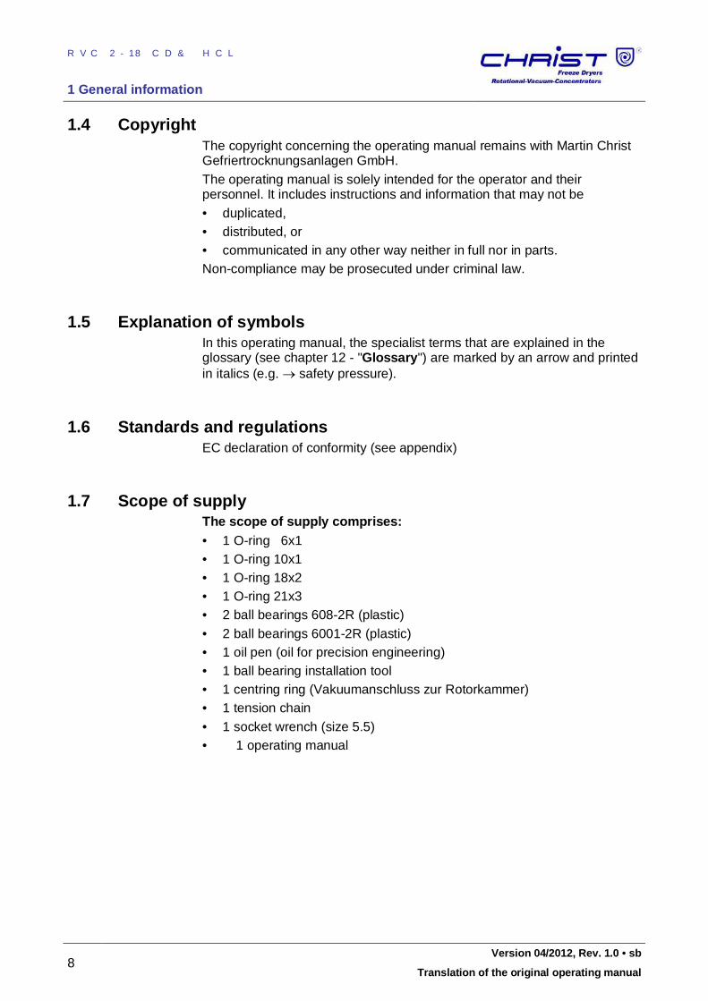
1.7 Scope of supply The scope of supply comprises: • 1 O-ring 6x1 • 1 O-ring 10x1 • 1 O-ring 18x2 • 1 O-ring 21x3 • 2 ball bearings 608-2R (plastic) • 2 ball bearings 6001-2R (plastic) • 1 oil pen (oil for precision engineering) • 1 ball bearing installation tool • 1 centring ring (Vakuumanschluss zur Rotorkammer) • 1 tension chain • 1 socket wrench (size 5.5) • 1 operating manual
RVC 2-18 CD&HCL
1 General information
Version 04/2012, Rev. 1.0 • sb 9
Translation of the original operating manual
Fig. 1: Scope of supply
Accessories and commissioning According to your order, our order confirmation, and our delivery note.
Pos: 15 / 010 Unive rsalm odul e/ Absc hnittsw echsel @ 0\ mod _12 021 245 140 62_0 .docx @ 4 18 @ @ 1
Pos: 16 / 010 Unive rsalm odul e/ Seit enwec hsel @ 0\m od_ 120 211 6244 312 _0. docx @ 10 5 @ @ 1
RVC 2-18 CD&HCL
2 Layout and mode of operation
10 Version 04/2012, Rev. 1.0 • sb
Translation of the original operating manual
Pos: 17 / 200 Christ /36 0 RVC-BA (STANDARDM ODULE)/ 020 Au fba u un d Wirku ngsw eise/0 20 A ufba u un d Wirk ungsw eise= == == === == == === == == === == == = @ 7 \mo d_1 309 255 680 878_ 68. docx @ 46 261 @ 1 @ 1
2 Layout and mode of operation Pos: 18 / 200 Christ /36 0 RVC-BA (STANDARDM ODULE)/ 020 Au fba u un d Wirku ngsw eise/0 20- 001 0 Auf bau des R otati ons-Vak uu m-Konz ent rato rs- --- -- --- -- --- -- --- --- -- --- -- --- --- -- --- -- - @ 7 \mo d_1 309 255 6817 37_ 68. docx @ 46 277 @ 2 @ 1
2.1 Layout of the RVC
Pos: 19 / 200 Christ /36 1 RVC-BA (PROJEKTE) /RVC 2-1 8 CDpl us_2 -18 CD plus_HCl /020 Aufb au u nd Wirk ungsw eise/ 020 -00 10- 001 1 Funkti ons- un d Bedie nele men te HCl @ 12\ mod _13 351 787 3543 3_6 8.d ocx @ 628 97 @ 3 @ 1
2.1.1 Functional and operating elements
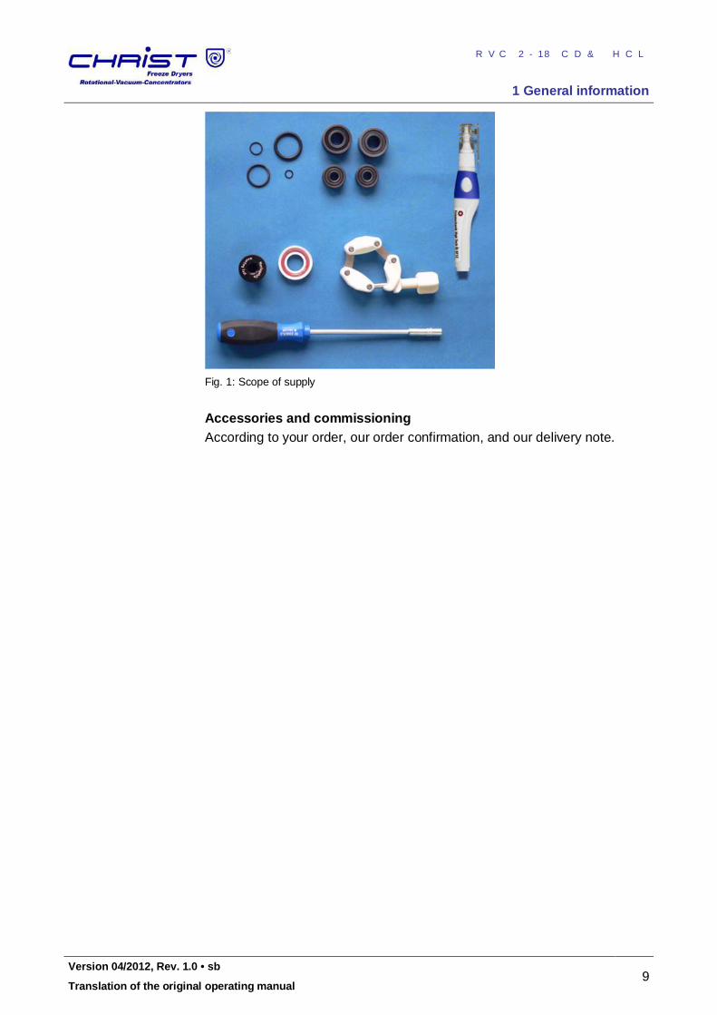
1 Lid lock device
2 Lid
3 Rotor chamber
4 User interface (see chapter 6.5.1 - "User interface")
5 Rotor shaft
6 Mains power switch
Fig. 1: Total view of the Rotational Vacuum Concentrator 2-18 CDplus HCl
7 Name plate (see chapter 2.1.2 - "Name plate")
8 Equipotential bonding screw (see chapter 3.7.4 - "Earth conductor check")
9 Connection for mains cable, with a fuse drawer
10 Electrical connection for the stop valve
11 Vacuum connection
12 Connection for aeration
Fig. 1: Rear view of the Rotational Vacuum Concentrator 2-18 CDplus HCl Pos: 20 / 010 Unive rsalm odul e/ L ee rzeile @ 0\ mod _120 211 624 450 0_0. docx @ 11 4 @ @ 1
Pos: 21 / 200 Christ /36 1 RVC-BA (PROJEKTE) /RVC 2-1 8 CDpl us_2 -18 CD plus_HCl /020 Aufb au u nd Wirk ungsw eise/ 020 -00 10- 002 1 Type nschild HCl @ 1 2\mo d_1 335 179 702 598 _68. docx @ 62 905 @ 3 @ 1
RVC 2-18 CD&HCL
2 Layout and mode of operation
Version 04/2012, Rev. 1.0 • sb 11
Translation of the original operating manual
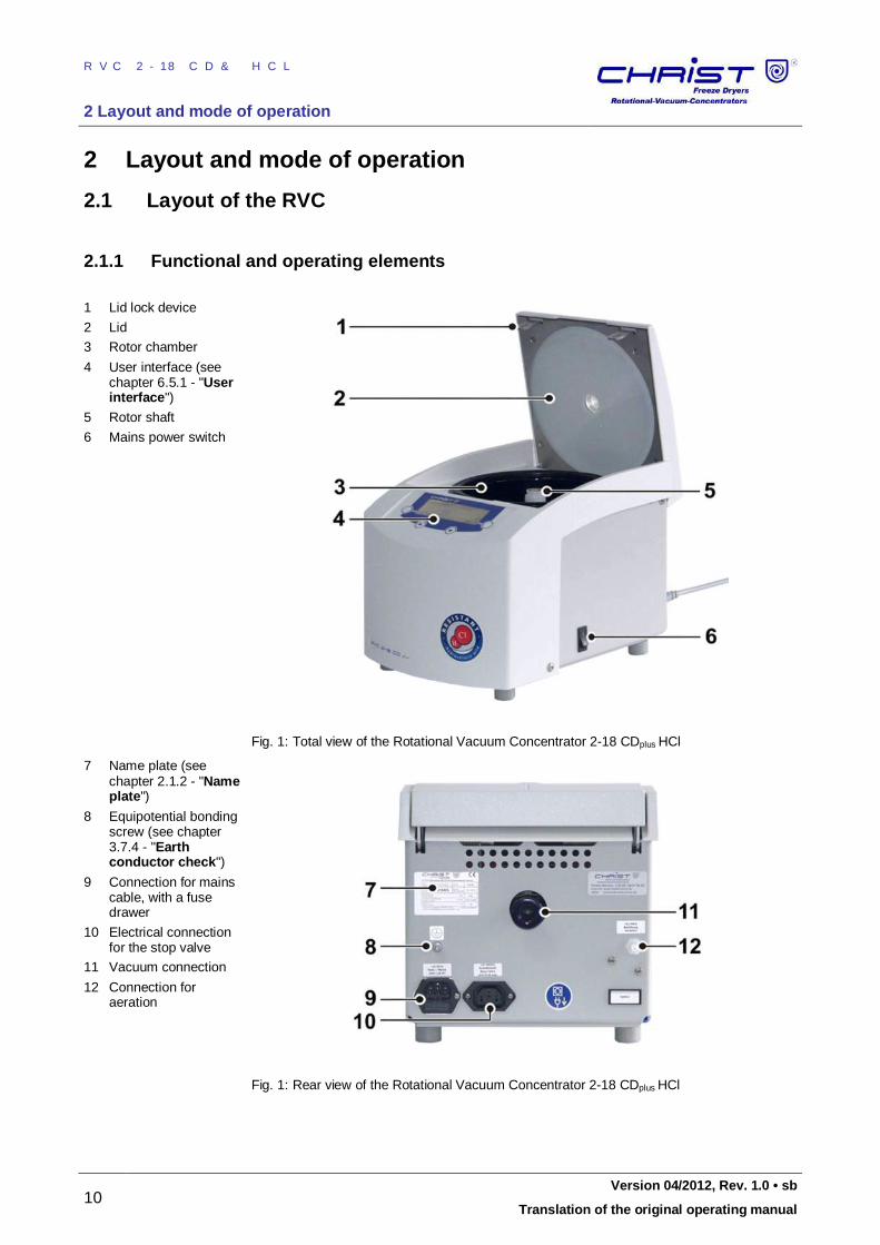
2.1.2 Name plate
1 Manufacturer
2 Registered office
3 Type
4 Serial number
5 Interference suppression
6 CE mark in compliance with the directive 2006/42/EC
7 Part number
8 Year of manufacture (month/year)
9 Power rating
10 Nominal voltage
11 Rated current 12 Country of origin
Fig. 2: Example of a name plate (enlarged photo) Pos: 22 / 010 Unive rsalm odul e/ Seit enwec hsel @ 0\m od_ 120 211 6244 312 _0. docx @ 10 5 @ @ 1
RVC 2-18 CD&HCL
2 Layout and mode of operation
12 Version 04/2012, Rev. 1.0 • sb
Translation of the original operating manual
Pos: 23 / 200 Christ /36 0 RVC-BA (STANDARDM ODULE)/ 020 Au fba u un d Wirku ngsw eise/0 20- 002 0 Wirk ungsw eise- -- --- -- --- -- --- --- -- --- -- --- --- -- --- -- --- -- --- --- -- --- -- @ 7\ mod _13 092 5568 523 7_6 8.do cx @ 4630 1 @ 2 @ 1
2.2 Mode of operation
Pos: 24 / 200 Christ /36 0 RVC-BA (STANDARDM ODULE)/ 020 Au fba u un d Wirku ngsw eise/0 20- 002 0-0 010 Prinzip de r Rot ations -Vaku um-K onze ntra tion @ 7\ mod _13 092 5568 564 3_6 8.do cx @ 4630 9 @ 3 @ 1
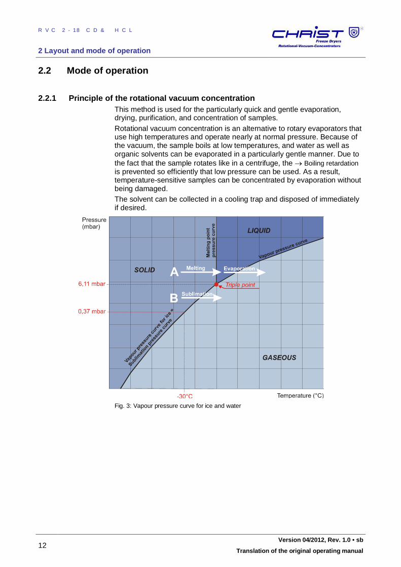
2.2.1 Principle of the rotational vacuum concentration This method is used for the particularly quick and gentle evaporation, drying, purification, and concentration of samples. Rotational vacuum concentration is an alternative to rotary evaporators that use high temperatures and operate nearly at normal pressure. Because of the vacuum, the sample boils at low temperatures, and water as well as organic solvents can be evaporated in a particularly gentle manner. Due to the fact that the sample rotates like in a centrifuge, the Boiling retardation is prevented so efficiently that low pressure can be used. As a result, temperature-sensitive samples can be concentrated by evaporation without being damaged. The solvent can be collected in a cooling trap and disposed of immediately if desired.
Fig. 3: Vapour pressure curve for ice and water
RVC 2-18 CD&HCL
2 Layout and mode of operation
Version 04/2012, Rev. 1.0 • sb 13
Translation of the original operating manual
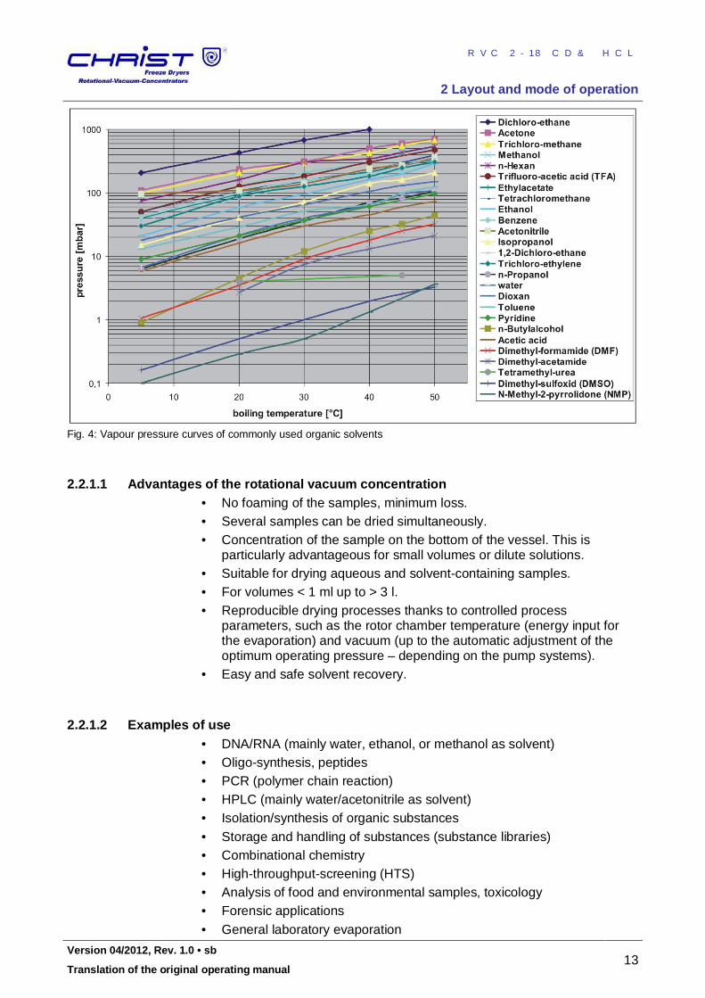
Fig. 4: Vapour pressure curves of commonly used organic solvents Pos: 25 / 010 Unive rsalm odul e/ L ee rzeile @ 0\ mod _120 211 624 450 0_0. docx @ 11 4 @ @ 1
Pos: 26 / 200 Christ /36 0 RVC-BA (STANDARDM ODULE)/ 020 Au fba u un d Wirku ngsw eise/0 20- 002 0-0 010 -00 10 Vo rteil e de r Rot ations -Vaku um -Konze ntr ation @ 7\ mod _13 092 556 8606 5_6 8.d ocx @ 463 17 @ 4 @ 1
2.2.1.1 Advantages of the rotational vacuum concentration • No foaming of the samples, minimum loss. • Several samples can be dried simultaneously. • Concentration of the sample on the bottom of the vessel. This is
particularly advantageous for small volumes or dilute solutions. • Suitable for drying aqueous and solvent-containing samples. • For volumes < 1 ml up to > 3 l. • Reproducible drying processes thanks to controlled process
parameters, such as the rotor chamber temperature (energy input for the evaporation) and vacuum (up to the automatic adjustment of the optimum operating pressure – depending on the pump systems).
• Easy and safe solvent recovery. Pos: 27 / 010 Unive rsalm odul e/ L ee rzeile @ 0\ mod _120 211 624 450 0_0. docx @ 11 4 @ @ 1
Pos: 28 / 200 Christ /36 0 RVC-BA (STANDARDM ODULE)/ 020 Au fba u un d Wirku ngsw eise/0 20- 002 0-0 020 -00 20 An wend ungs beispi ele @ 7\m od_ 130 925 568 6847 _68 .docx @ 4 633 3 @ 4 @ 1
2.2.1.2 Examples of use • DNA/RNA (mainly water, ethanol, or methanol as solvent) • Oligo-synthesis, peptides • PCR (polymer chain reaction) • HPLC (mainly water/acetonitrile as solvent) • Isolation/synthesis of organic substances • Storage and handling of substances (substance libraries) • Combinational chemistry • High-throughput-screening (HTS) • Analysis of food and environmental samples, toxicology • Forensic applications • General laboratory evaporation
RVC 2-18 CD&HCL
3 Safety
14 Version 04/2012, Rev. 1.0 • sb
Translation of the original operating manual
Pos: 29 / 010 Unive rsalm odul e/ Absc hnittsw echsel @ 0\ mod _12 021 245 140 62_0 .docx @ 4 18 @ @ 1 Pos: 30 / 010 Unive rsalm odul e/ Seit enwec hsel @ 0\m od_ 120 211 6244 312 _0. docx @ 10 5 @ @ 1 Pos: 31 / 200 Christ /36 0 RVC-BA (STANDARDM ODULE)/ 030 Sich erh eit/0 30 Sic her heit= == == === == == === == == == === == == === == == @ 7\ mod _13 0933 103 683 4_6 8.do cx @ 4 639 1 @ 1 @ 1
3 Safety Pos: 32 / 200 Christ /36 0 RVC-BA (STANDARDM ODULE)/ 030 Sich erh eit/0 30- 001 0 Besc hilde run g des Ge räts @ 7\ mod _130 933 103 719 3_6 8.doc x @ 4 639 9 @ 2 @ 1
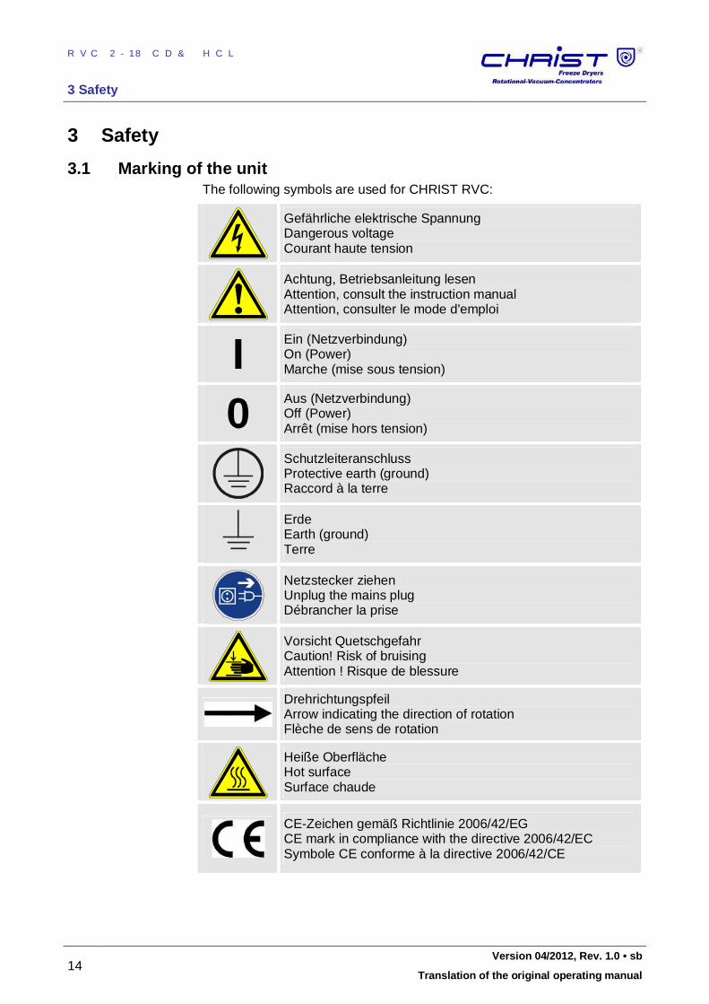
3.1 Marking of the unit The following symbols are used for CHRIST RVC:
Gefährliche elektrische Spannung Dangerous voltage Courant haute tension
Achtung, Betriebsanleitung lesen Attention, consult the instruction manual Attention, consulter le mode d'emploi
I
Ein (Netzverbindung) On (Power) Marche (mise sous tension)
0
Aus (Netzverbindung) Off (Power) Arrêt (mise hors tension)
Schutzleiteranschluss Protective earth (ground) Raccord à la terre
Erde Earth (ground) Terre
Netzstecker ziehen Unplug the mains plug Débrancher la prise
Vorsicht Quetschgefahr Caution! Risk of bruising Attention ! Risque de blessure
Drehrichtungspfeil Arrow indicating the direction of rotation Flèche de sens de rotation
Heiße Oberfläche Hot surface Surface chaude
CE-Zeichen gemäß Richtlinie 2006/42/EG CE mark in compliance with the directive 2006/42/EC Symbole CE conforme à la directive 2006/42/CE
Pos: 33 / 200 Christ /36 0 RVC-BA (STANDARDM ODULE)/ 030 Sich erh eit/0 30- 002 0 Sym bol- un d Hinweis erklä run gen @ 7\ mod _13 093 310 376 15_6 8.d ocx @ 464 07 @ 2 @ 1
RVC 2-18 CD&HCL
3 Safety
Version 04/2012, Rev. 1.0 • sb 15
Translation of the original operating manual
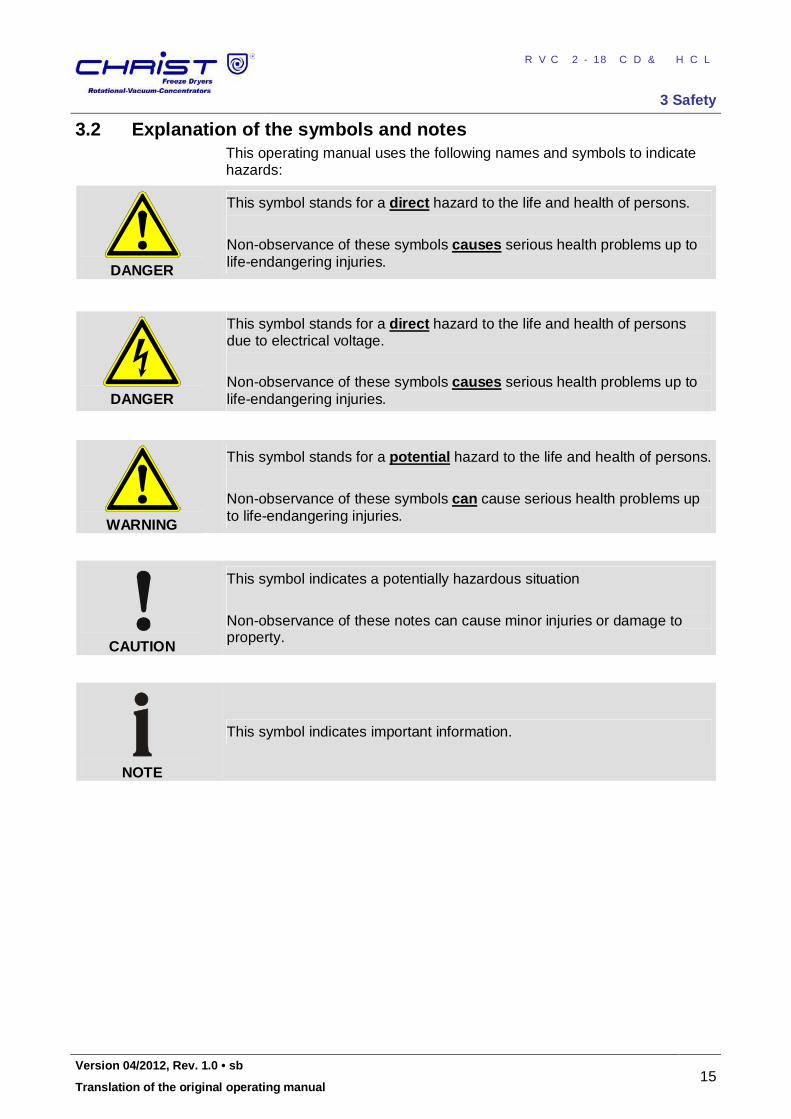
3.2 Explanation of the symbols and notes This operating manual uses the following names and symbols to indicate hazards:
DANGER
This symbol stands for a direct hazard to the life and health of persons.
Non-observance of these symbols causes serious health problems up to life-endangering injuries.
DANGER
This symbol stands for a direct hazard to the life and health of persons due to electrical voltage. Non-observance of these symbols causes serious health problems up to life-endangering injuries.
WARNING
This symbol stands for a potential hazard to the life and health of persons.
Non-observance of these symbols can cause serious health problems up to life-endangering injuries.
CAUTION
This symbol indicates a potentially hazardous situation Non-observance of these notes can cause minor injuries or damage to property.
NOTE
This symbol indicates important information.
Pos: 34 / 010 Unive rsalm odul e/ Seit enwec hsel @ 0\m od_ 120 211 6244 312 _0. docx @ 10 5 @ @ 1
RVC 2-18 CD&HCL
3 Safety
16 Version 04/2012, Rev. 1.0 • sb
Translation of the original operating manual
Pos: 35 / 200 Christ /36 0 RVC-BA (STANDARDM ODULE)/ 030 Sich erh eit/0 30- 003 0 Ve rantw ort ung des Be treib ers @ 7\ mod _13 093 310 3800 5_6 8.d ocx @ 464 15 @ 2 @ 1
3.3 Responsibility of the operator The operator is responsible for authorising only qualified personnel to work on the RVC (see chapter 3.4 - "Operating personnel"). The areas of responsibility of the personnel concerning the operation, maintenance, and care of the unit must be clearly defined. The safety-conscious work of the personnel in compliance with the operating manual and the relevant EC and national health and safety regulations as well as with the accident prevention regulations must be checked at regular intervals (e.g. every month). The RVC must be maintained regularly (see chapter 8 - "Maintenance and service").
Pos: 36 / 010 Unive rsalm odul e/ L ee rzeile @ 0\ mod _120 211 624 450 0_0. docx @ 11 4 @ @ 1
Pos: 37 / 200 Christ /36 0 RVC-BA (STANDARDM ODULE)/ 030 Sich erh eit/0 30- 004 0 Be dienp ers onal @ 7\ mod _130 933 103 834 9_6 8.doc x @ 4 642 3 @ 2 @ 1
3.4 Operating personnel Persons operating the unit must • be familiar with the fundamental regulations concerning workplace
safety and accident prevention • have read and understood this operating manual (and in particular the
safety sections and warning notes) and confirmed this with their signature.
Pos: 38 / 010 Unive rsalm odul e/ L ee rzeile @ 0\ mod _120 211 624 450 0_0. docx @ 11 4 @ @ 1
Pos: 39 / 200 Christ /36 0 RVC-BA (STANDARDM ODULE)/ 030 Sich erh eit/0 30- 005 0 I nfor melle Sicher heits hinweise @ 7\ mo d_13 093 310 386 93_ 68.d ocx @ 464 31 @ 2 @ 1
3.5 Informal safety instructions This operating manual is part of the product. • The operating manual must be kept at the location of use of the RVC.
Ensure that it is accessible at all times. • The operating manual must be handed over to any subsequent owner
or operator of the RVC. • Any changes made must be added to the operating manual. • In addition to the operating manual, the general and local rules and
regulations concerning the prevention of accidents and the protection of the environment must also be supplied.
• Safety and danger indications on the RVC must be kept readable at all times. If necessary, they must be replaced.
Pos: 40 / 010 Unive rsalm odul e/ Seit enwec hsel @ 0\m od_ 120 211 6244 312 _0. docx @ 10 5 @ @ 1
RVC 2-18 CD&HCL
3 Safety
Version 04/2012, Rev. 1.0 • sb 17
Translation of the original operating manual
Pos: 41 / 200 Christ /36 0 RVC-BA (STANDARDM ODULE)/ 030 Sich erh eit/0 30- 006 0 Sich erh eitshinw eise- -- --- --- -- --- -- --- --- -- --- -- --- -- --- --- -- --- - @ 7\m od_ 1309 331 039 036 _68. docx @ 46 439 @ 2 @ 1
3.6 Safety instructions Pos: 42 / 200 Christ /36 0 RVC-BA (STANDARDM ODULE)/ 030 Sich erh eit/0 30- 006 0-0 010 Elektris che Sich erh eit @ 7\m od_ 130 933 1039 396 _68 .docx @ 46 447 @ 3 @ 1
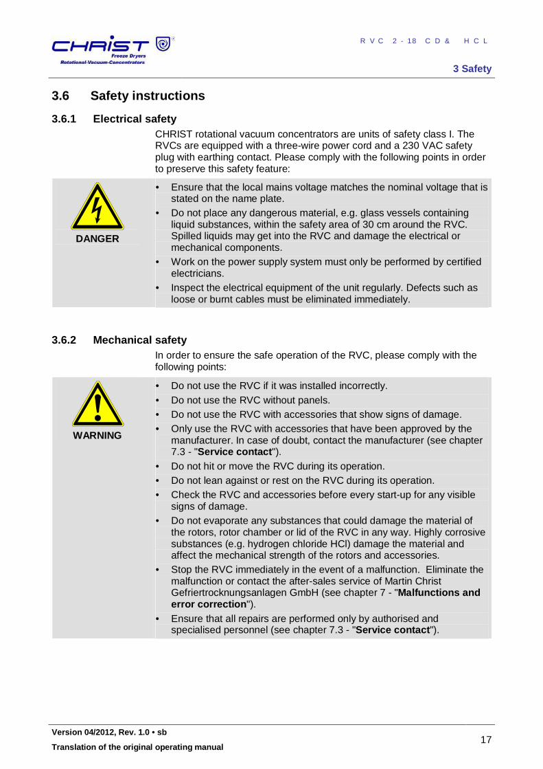
3.6.1 Electrical safety CHRIST rotational vacuum concentrators are units of safety class I. The RVCs are equipped with a three-wire power cord and a 230 VAC safety plug with earthing contact. Please comply with the following points in order to preserve this safety feature:
DANGER
• Ensure that the local mains voltage matches the nominal voltage that is stated on the name plate.
• Do not place any dangerous material, e.g. glass vessels containing liquid substances, within the safety area of 30 cm around the RVC. Spilled liquids may get into the RVC and damage the electrical or mechanical components.
• Work on the power supply system must only be performed by certified electricians.
• Inspect the electrical equipment of the unit regularly. Defects such as loose or burnt cables must be eliminated immediately.
Pos: 43 / 010 Unive rsalm odul e/ L ee rzeile @ 0\ mod _120 211 624 450 0_0. docx @ 11 4 @ @ 1
Pos: 44 / 200 Christ /36 0 RVC-BA (STANDARDM ODULE)/ 030 Sich erh eit/0 30- 006 0-0 020 M echa nische Sic her heit @ 7\ mod_ 130 933 103 975 5_6 8.docx @ 4 645 5 @ 3 @ 1
3.6.2 Mechanical safety In order to ensure the safe operation of the RVC, please comply with the following points:
WARNING
• Do not use the RVC if it was installed incorrectly. • Do not use the RVC without panels. • Do not use the RVC with accessories that show signs of damage. • Only use the RVC with accessories that have been approved by the
manufacturer. In case of doubt, contact the manufacturer (see chapter 7.3 - "Service contact").
• Do not hit or move the RVC during its operation. • Do not lean against or rest on the RVC during its operation. • Check the RVC and accessories before every start-up for any visible
signs of damage. • Do not evaporate any substances that could damage the material of
the rotors, rotor chamber or lid of the RVC in any way. Highly corrosive substances (e.g. hydrogen chloride HCl) damage the material and affect the mechanical strength of the rotors and accessories.
• Stop the RVC immediately in the event of a malfunction. Eliminate the malfunction or contact the after-sales service of Martin Christ Gefriertrocknungsanlagen GmbH (see chapter 7 - "Malfunctions and error correction").
• Ensure that all repairs are performed only by authorised and specialised personnel (see chapter 7.3 - "Service contact").
Pos: 45 / 010 Unive rsalm odul e/ Seit enwec hsel @ 0\m od_ 120 211 6244 312 _0. docx @ 10 5 @ @ 1
RVC 2-18 CD&HCL
3 Safety
18 Version 04/2012, Rev. 1.0 • sb
Translation of the original operating manual
Pos: 46 / 200 Christ /36 0 RVC-BA (STANDARDM ODULE)/ 030 Sich erh eit/0 30- 006 0-0 030 Bra ndsch utz @ 7\m od_ 130 933 104 011 5_68 .docx @ 4 646 3 @ 3 @ 1
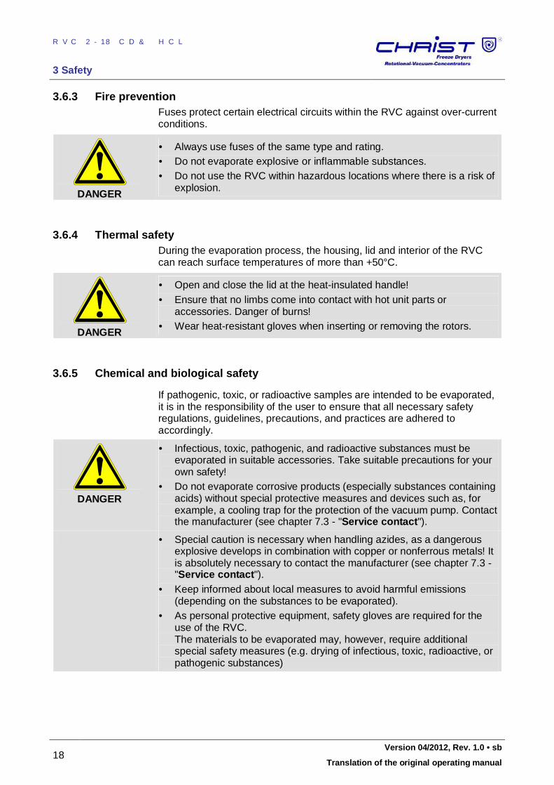
3.6.3 Fire prevention Fuses protect certain electrical circuits within the RVC against over-current conditions.
DANGER
• Always use fuses of the same type and rating. • Do not evaporate explosive or inflammable substances. • Do not use the RVC within hazardous locations where there is a risk of
explosion. Pos: 47 / 010 Unive rsalm odul e/ L ee rzeile @ 0\ mod _120 211 624 450 0_0. docx @ 11 4 @ @ 1
Pos: 48 / 200 Christ /36 0 RVC-BA (STANDARDM ODULE)/ 030 Sich erh eit/0 30- 006 0-0 040 Ther misch e Siche rheit @ 7\ mod _13 093 310 4047 4_6 8.d ocx @ 464 71 @ 3 @ 1
3.6.4 Thermal safety During the evaporation process, the housing, lid and interior of the RVC can reach surface temperatures of more than +50°C.
DANGER
• Open and close the lid at the heat-insulated handle! • Ensure that no limbs come into contact with hot unit parts or
accessories. Danger of burns! • Wear heat-resistant gloves when inserting or removing the rotors.
Pos: 49 / 010 Unive rsalm odul e/ L ee rzeile @ 0\ mod _120 211 624 450 0_0. docx @ 11 4 @ @ 1
Pos: 50 / 200 Christ /36 0 RVC-BA (STANDARDM ODULE)/ 030 Sich erh eit/0 30- 006 0-0 050 Che misch e un d biol ogisch e Siche rheit @ 7\ mo d_13 093 310 408 18_ 68.d ocx @ 464 79 @ 3 @ 1
3.6.5 Chemical and biological safety
If pathogenic, toxic, or radioactive samples are intended to be evaporated, it is in the responsibility of the user to ensure that all necessary safety regulations, guidelines, precautions, and practices are adhered to accordingly.
DANGER
• Infectious, toxic, pathogenic, and radioactive substances must be evaporated in suitable accessories. Take suitable precautions for your own safety!
• Do not evaporate corrosive products (especially substances containing acids) without special protective measures and devices such as, for example, a cooling trap for the protection of the vacuum pump. Contact the manufacturer (see chapter 7.3 - "Service contact").
• Special caution is necessary when handling azides, as a dangerous explosive develops in combination with copper or nonferrous metals! It is absolutely necessary to contact the manufacturer (see chapter 7.3 - "Service contact").
• Keep informed about local measures to avoid harmful emissions (depending on the substances to be evaporated).
• As personal protective equipment, safety gloves are required for the use of the RVC. The materials to be evaporated may, however, require additional special safety measures (e.g. drying of infectious, toxic, radioactive, or pathogenic substances)
Pos: 51 / 010 Unive rsalm odul e/ L ee rzeile @ 0\ mod _120 211 624 450 0_0. docx @ 11 4 @ @ 1
Pos: 52 / 200 Christ /36 0 RVC-BA (STANDARDM ODULE)/ 030 Sich erh eit/0 30- 006 0-0 060 Siche rheits hinweis e zu r Evap orati on @ 7\m od_ 130 933 104 119 3_68 .docx @ 4 648 7 @ 3 @ 1
RVC 2-18 CD&HCL
3 Safety
Version 04/2012, Rev. 1.0 • sb 19
Translation of the original operating manual
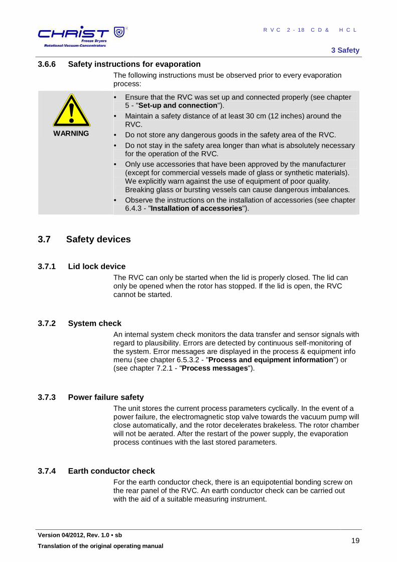
3.6.6 Safety instructions for evaporation The following instructions must be observed prior to every evaporation process:
WARNING
• Ensure that the RVC was set up and connected properly (see chapter 5 - "Set-up and connection").
• Maintain a safety distance of at least 30 cm (12 inches) around the RVC.
• Do not store any dangerous goods in the safety area of the RVC. • Do not stay in the safety area longer than what is absolutely necessary
for the operation of the RVC. • Only use accessories that have been approved by the manufacturer
(except for commercial vessels made of glass or synthetic materials). We explicitly warn against the use of equipment of poor quality. Breaking glass or bursting vessels can cause dangerous imbalances.
• Observe the instructions on the installation of accessories (see chapter 6.4.3 - "Installation of accessories").
Pos: 53 / 010 Unive rsalm odul e/ L ee rzeile @ 0\ mod _120 211 624 450 0_0. docx @ 11 4 @ @ 1
Pos: 54 / 200 Christ /36 0 RVC-BA (STANDARDM ODULE)/ 030 Sich erh eit/0 30- 007 0 Sich erh eitsein richtu nge n- --- --- -- --- -- --- -- --- --- -- --- -- --- --- -- --- -- --- -- --- - @ 7\mo d_1 309 331 041 552 _68. docx @ 46 495 @ 2 @ 1
3.7 Safety devices
Pos: 55 / 200 Christ /36 0 RVC-BA (STANDARDM ODULE)/ 030 Sich erh eit/0 30- 007 0-0 010 Deck elver rieg elung @ 7\ mo d_1 3093 340 838 55_ 68.d ocx @ 465 35 @ 3 @ 1
3.7.1 Lid lock device The RVC can only be started when the lid is properly closed. The lid can only be opened when the rotor has stopped. If the lid is open, the RVC cannot be started.
Pos: 56 / 010 Unive rsalm odul e/ L ee rzeile @ 0\ mod _120 211 624 450 0_0. docx @ 11 4 @ @ 1
Pos: 57 / 200 Christ /36 0 RVC-BA (STANDARDM ODULE)/ 030 Sich erh eit/0 30- 007 0-0 020 Syste mkon trolle @ 7\ mo d_13 093 310 418 96_ 68.d ocx @ 465 03 @ 3 @ 1
3.7.2 System check An internal system check monitors the data transfer and sensor signals with regard to plausibility. Errors are detected by continuous self-monitoring of the system. Error messages are displayed in the process & equipment info menu (see chapter 6.5.3.2 - "Process and equipment information") or (see chapter 7.2.1 - "Process messages").
Pos: 58 / 010 Unive rsalm odul e/ L ee rzeile @ 0\ mod _120 211 624 450 0_0. docx @ 11 4 @ @ 1
Pos: 59 / 200 Christ /36 1 RVC-BA (PROJEKTE) /RVC 2-1 8 CDpl us_2 -18 CD plus_HCl /030 Sicher heit/ 030 -00 70- 003 0 Ne tzausf allsiche rheit 2- 18_ 2-1 8HCl @ 1 2\m od_ 133 541 7298 636 _68 .docx @ 6 4042 @ 3 3 @ 1
3.7.3 Power failure safety The unit stores the current process parameters cyclically. In the event of a power failure, the electromagnetic stop valve towards the vacuum pump will close automatically, and the rotor decelerates brakeless. The rotor chamber will not be aerated. After the restart of the power supply, the evaporation process continues with the last stored parameters.
Pos: 60 / 010 Unive rsalm odul e/ L ee rzeile @ 0\ mod _120 211 624 450 0_0. docx @ 11 4 @ @ 1
Pos: 61 / 200 Christ /36 0 RVC-BA (STANDARDM ODULE)/ 030 Sich erh eit/0 30- 007 0-0 040 Schut zleite rpr üfun g @ 7\mo d_1 309 331 042 239 _68. docx @ 46 511 @ 3 @ 1
3.7.4 Earth conductor check For the earth conductor check, there is an equipotential bonding screw on the rear panel of the RVC. An earth conductor check can be carried out with the aid of a suitable measuring instrument.
Pos: 62 / 010 Unive rsalm odul e/ L ee rzeile @ 0\ mod _120 211 624 450 0_0. docx @ 11 4 @ @ 1
Pos: 63 / 200 Christ /36 0 RVC-BA (STANDARDM ODULE)/ 030 Sich erh eit/0 30- 008 0 Ve rhalt en b ei Ge fah ren und U nfälle n @ 7\m od_ 1309 331 042 583 _68. docx @ 46 519 @ 2 @ 1
RVC 2-18 CD&HCL
3 Safety
20 Version 04/2012, Rev. 1.0 • sb
Translation of the original operating manual
3.8 Measures in the event of hazards and accidents
DANGER
• Cool all burns immediately in cold water (10 – 20°C) for 5 minutes. Cover the burnt skin areas with sterile material.
• A fire in the electrical control system must be extinguished with a CO2 extinguisher!
• If in doubt, call the emergency doctor! Pos: 64 / 010 Unive rsalm odul e/ L ee rzeile @ 0\ mod _120 211 624 450 0_0. docx @ 11 4 @ @ 1
Pos: 65 / 200 Christ /36 0 RVC-BA (STANDARDM ODULE)/ 030 Sich erh eit/0 30- 009 0 Re strisike n @ 7\m od_1 309 331 042 927 _68. docx @ 46 527 @ 2 @ 1
3.9 Remaining hazards All CHRIST rotational vacuum concentrators were built state- of- the- art and according to the accepted safety rules. However, danger to life and limb of the operator, or of third parties, or impairments of the units or other material assets cannot be completely excluded when the units are being used. • Use the RVC only for the purpose that it was originally intended for (see
chapter 1.2 - "Intended use").
• Use the RVC only if it is in a perfect running state. • Immediately eliminate any problems that can affect safety.
Pos: 66 / 010 Unive rsalm odul e/ Absc hnittsw echsel @ 0\ mod _12 021 245 140 62_0 .docx @ 4 18 @ @ 1
Pos: 67 / 010 Unive rsalm odul e/ Seit enwec hsel @ 0\m od_ 120 211 6244 312 _0. docx @ 10 5 @ @ 1
RVC 2-18 CD&HCL
4 Storage and transport
Version 04/2012, Rev. 1.0 • sb 21
Translation of the original operating manual
Pos: 68 / 200 Christ /36 0 RVC-BA (STANDARDM ODULE)/ 040 Lag eru ng u nd Tra nsp ort/ 040 La ger ung und Tr ansp ort == == === == == === == == === == == == @ 7\ mod_ 130 933 471 646 4_6 8.doc x @ 4 654 9 @ 1 @ 1
4 Storage and transport
Pos: 69 / 200 Christ /36 0 RVC-BA (STANDARDM ODULE)/ 040 Lag eru ng u nd Tra nsp ort/ 040 -00 10 Lag erb eding ung en @ 8\ mod_ 130 933 471 722 9_6 8.doc x @ 4 656 5 @ 2 @ 1
4.1 Storage conditions In order to ensure the protection against mechanical and climatic influences, the guidelines of the German Federal Association for Wooden Packages, Pallets, and Export Packaging (Bundesverband Holzpackmittel, Paletten, Exportverpackung e.V.), the so-called HPE packaging guidelines, must be applied when packing and storing the RVC. The storage must be: • dust-free • dry • free from excessive temperature fluctuations • free from mechanical load.
Pos: 70 / 010 Unive rsalm odul e/ L ee rzeile @ 0\ mod _120 211 624 450 0_0. docx @ 11 4 @ @ 1
Pos: 71 / 200 Christ /36 1 RVC-BA (PROJEKTE) /RVC 2-1 8 CDpl us_2 -18 CD plus_HCl /040 La ger ung und Tr ansp ort/ 040 -00 21 Abme ssun gen und Gewich t HCl @ 1 2\m od_ 133 518 016 0636 _68 .docx @ 6 291 3 @ 2 @ 1
4.2 Dimensions and weight Values for the RVC without a vacuum pump:
RVC 2-18 CDplus HCl
Height: 240 mm
Height with open lid: 255 mm
Width: 242 mm
Depth (incl. vacuum flange connection) 355 mm
Weight: approx. 14 kg
Pos: 72 / 010 Unive rsalm odul e/ L ee rzeile @ 0\ mod _120 211 624 450 0_0. docx @ 11 4 @ @ 1
Pos: 73 / 200 Christ /36 1 RVC-BA (PROJEKTE) /RVC 2-1 8 CDpl us_2 -18 CD plus_HCl /040 La ger ung und Tr ansp ort/ 040 -00 31 Ve rp ackun g HCl @ 12\ mod_ 133 518 025 805 2_6 8.doc x @ 6 292 1 @ 2 @ 1
4.3 Packaging The RVC is packaged in a cardboard box or in a wooden crate, depending on the scope of supply. • After opening the packaging, take out the box containing the
accessories. • Remove the packaging material. • Lift the RVC upwards and out of the crate/cardboard box with a
sufficient number of people to lift it safely. When lifting the unit, always reach under it from the side.
CAUTION
The RVC 2-18 CDplus HCl weighs approx. 14 kg!
• Retain the packaging for any possible future transport of the RVC.
Pos: 74 / 010 Unive rsalm odul e/ Seit enwec hsel @ 0\m od_ 120 211 6244 312 _0. docx @ 10 5 @ @ 1
RVC 2-18 CD&HCL
4 Storage and transport
22 Version 04/2012, Rev. 1.0 • sb
Translation of the original operating manual
Pos: 75 / 200 Christ /36 1 RVC-BA (PROJEKTE) /RVC 2-1 8 CDpl us_2 -18 CD plus_HCl /040 La ger ung und Tr ansp ort/ 040 -00 41 Tr ans portsic her ung HCl @ 1 2\m od_ 133 697 3510 317 _68 .docx @ 6 4439 @ 2 2 @ 1
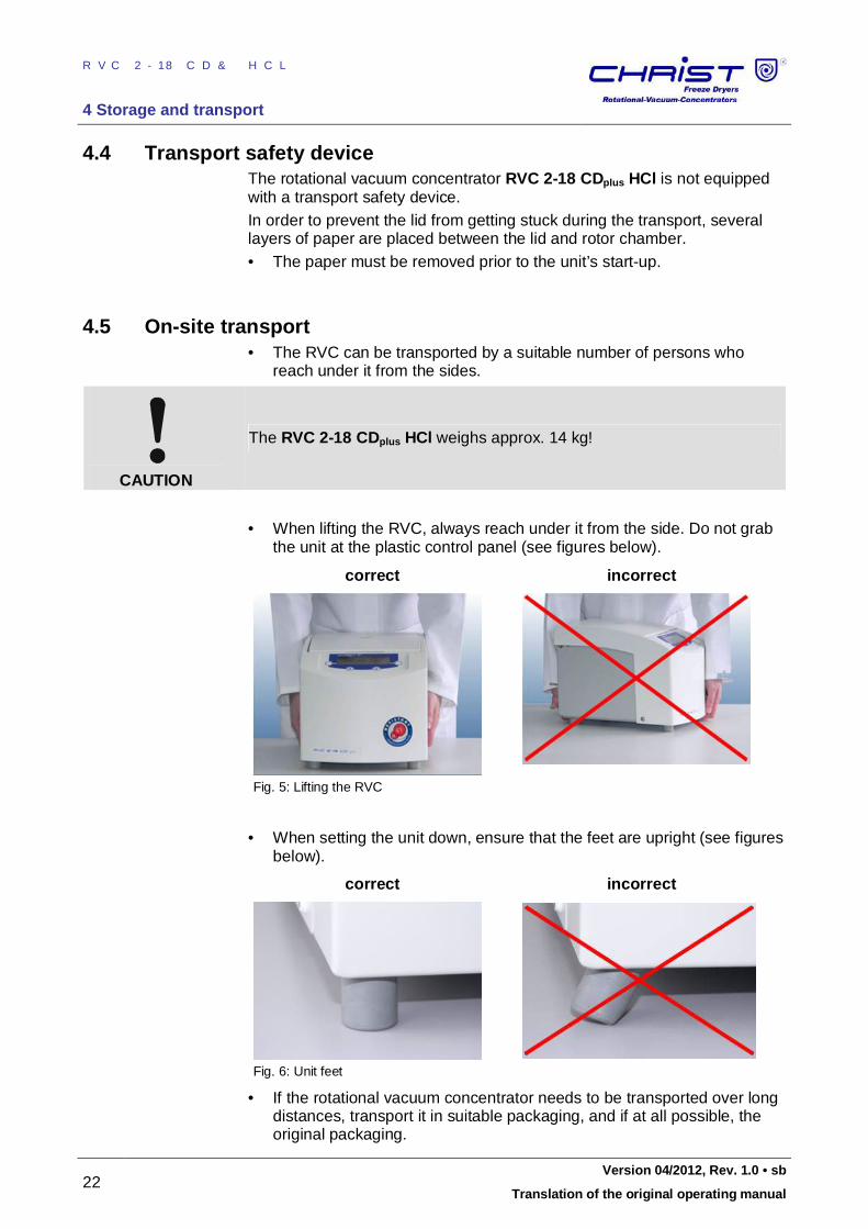
4.4 Transport safety device The rotational vacuum concentrator RVC 2-18 CDplus HCl is not equipped with a transport safety device. In order to prevent the lid from getting stuck during the transport, several layers of paper are placed between the lid and rotor chamber. • The paper must be removed prior to the unit’s start-up.
Pos: 76 / 010 Unive rsalm odul e/ L ee rzeile @ 0\ mod _120 211 624 450 0_0. docx @ 11 4 @ @ 1
Pos: 77 / 200 Christ /36 1 RVC-BA (PROJEKTE) /RVC 2-1 8 CDpl us_2 -18 CD plus_HCl /040 La ger ung und Tr ansp ort/ 040 -00 51 Inn erb etrie bliche r T rans por t HCl @ 12\m od_ 133 518 031 151 0_6 8.docx @ 6 292 9 @ 2 @ 1
4.5 On-site transport • The RVC can be transported by a suitable number of persons who
reach under it from the sides.
CAUTION
The RVC 2-18 CDplus HCl weighs approx. 14 kg!
• When lifting the RVC, always reach under it from the side. Do not grab
the unit at the plastic control panel (see figures below).
correct incorrect
Fig. 5: Lifting the RVC
• When setting the unit down, ensure that the feet are upright (see figures
below).
correct incorrect
Fig. 6: Unit feet
• If the rotational vacuum concentrator needs to be transported over long distances, transport it in suitable packaging, and if at all possible, the original packaging.
Pos: 78 / 010 Unive rsalm odul e/ Absc hnittsw echsel @ 0\ mod _12 021 245 140 62_0 .docx @ 4 18 @ @ 1 Pos: 79 / 010 Unive rsalm odul e/ Seit enwec hsel @ 0\m od_ 120 211 6244 312 _0. docx @ 10 5 @ @ 1
RVC 2-18 CD&HCL
5 Set-up and connection
Version 04/2012, Rev. 1.0 • sb 23
Translation of the original operating manual
Pos: 80 / 200 Christ /36 0 RVC-BA (STANDARDM ODULE)/ 050 Au fstellu ng u nd Ans chluss/ 050 Aufst ellung un d Anschl uss= === == == === == == === == == == == @ 8\m od_ 130 933 583 2534 _68 .docx @ 4 658 1 @ 1 @ 1
5 Set-up and connection
Pos: 81 / 200 Christ /36 0 RVC-BA (STANDARDM ODULE)/ 050 Au fstellu ng u nd Ans chluss/ 050 -00 30 A ufstello rt, Eins atzo rt @ 8\m od_ 130 9335 833 534 _68 .docx @ 46 605 @ 2 @ 1
5.1 Installation site Operate the RVC only in closed and dry rooms. • The table must be stable and have a solid, even tabletop. • Ensure sufficient ventilation. Do not place any paper, cloth, or similar
material behind or under the unit, since otherwise the air circulation will be impaired.
• Keep a safety distance of at least 30 cm from the wall so that the vents in the unit remain fully effective.
• The ambient temperature must be in the range of +10°C to +25°C. • Do not subject the RVC to thermal stress, e.g. by positioning it near
heat generators. • Avoid direct sunlight (UV radiation).
Pos: 82 / 010 Unive rsalm odul e/ L ee rzeile @ 0\ mod _120 211 624 450 0_0. docx @ 11 4 @ @ 1
Pos: 83 / 200 Christ /36 0 RVC-BA (STANDARDM ODULE)/ 050 Au fstellu ng u nd Ans chluss/ 050 -00 40 E ner gieve rsor gun g-- -- --- -- --- --- -- --- -- --- -- --- --- -- --- - @ 8\m od_ 1309 335 833 862 _68. docx @ 46 613 @ 2 @ 1
5.2 Power supply
Pos: 84 / 200 Christ /36 1 RVC-BA (PROJEKTE) /RVC 2-1 8 CDpl us_2 -18 CD plus_HCl /050 Aufstell ung und Anschluss /05 0-0 040 -00 11 An schluss art HCl @ 1 2\mo d_1 336 975 260 064 _68. docx @ 64 463 @ 33 @ 1
5.2.1 Connection
DANGER
The operating voltage on the name plate must correspond to the local supply voltage
CHRIST rotational vacuum concentrators are units of safety class I.Units of the type RVC 2-18 CDplus HCl have a three-wire power cord with an IEC C13 connector . An equipotential bonding screw is located on the back . This equipotential bonding screw can be used to perform an earth conductor check.
Pos: 85 / 010 Unive rsalm odul e/ L ee rzeile @ 0\ mod _120 211 624 450 0_0. docx @ 11 4 @ @ 1
Pos: 86 / 200 Christ /36 0 RVC-BA (STANDARDM ODULE)/ 050 Au fstellu ng u nd Ans chluss/ 050 -00 40- 002 0 Sich eru nge n ba useits @ 8\ mod _13 093 3583 459 6_6 8.do cx @ 4662 9 @ 3 @ 1
5.2.2 Customer-provided fuses Typically, the RVC must be protected with 16 Amp G fuses that are to be provided by the customer.
Pos: 87 / 010 Unive rsalm odul e/ Seit enwec hsel @ 0\m od_ 120 211 6244 312 _0. docx @ 10 5 @ @ 1
RVC 2-18 CD&HCL
5 Set-up and connection
24 Version 04/2012, Rev. 1.0 • sb
Translation of the original operating manual
Pos: 88 / 200 Christ /36 0 RVC-BA (STANDARDM ODULE)/ 050 Au fstellu ng u nd Ans chluss/ 050 -00 40- 003 0 Belü ftun gsve ntil @ 8 \mo d_1 309 419 3887 00_ 68. docx @ 46 708 @ 3 @ 1
5.2.3 Aeration valve The RVC is equipped with an electromagnetic aeration valve. The rotor chamber is aerated through this valve after the end of the evaporation process.
NOTE
Unpressurised inert gas can also be used for aerating the rotor chamber.
Pos: 89 / 010 Unive rsalm odul e/ L ee rzeile @ 0\ mod _120 211 624 450 0_0. docx @ 11 4 @ @ 1
Pos: 90 / 200 Christ /36 1 RVC-BA (PROJEKTE) /RVC 2-1 8 CDpl us_2 -18 CD plus_HCl /050 Aufstell ung und Anschluss /05 0-0 040 -00 31 Va kuu mver bind ung en HCl @ 12\ mod _13 354 274 921 60_ 68.d ocx @ 640 82 @ 3 @ 1
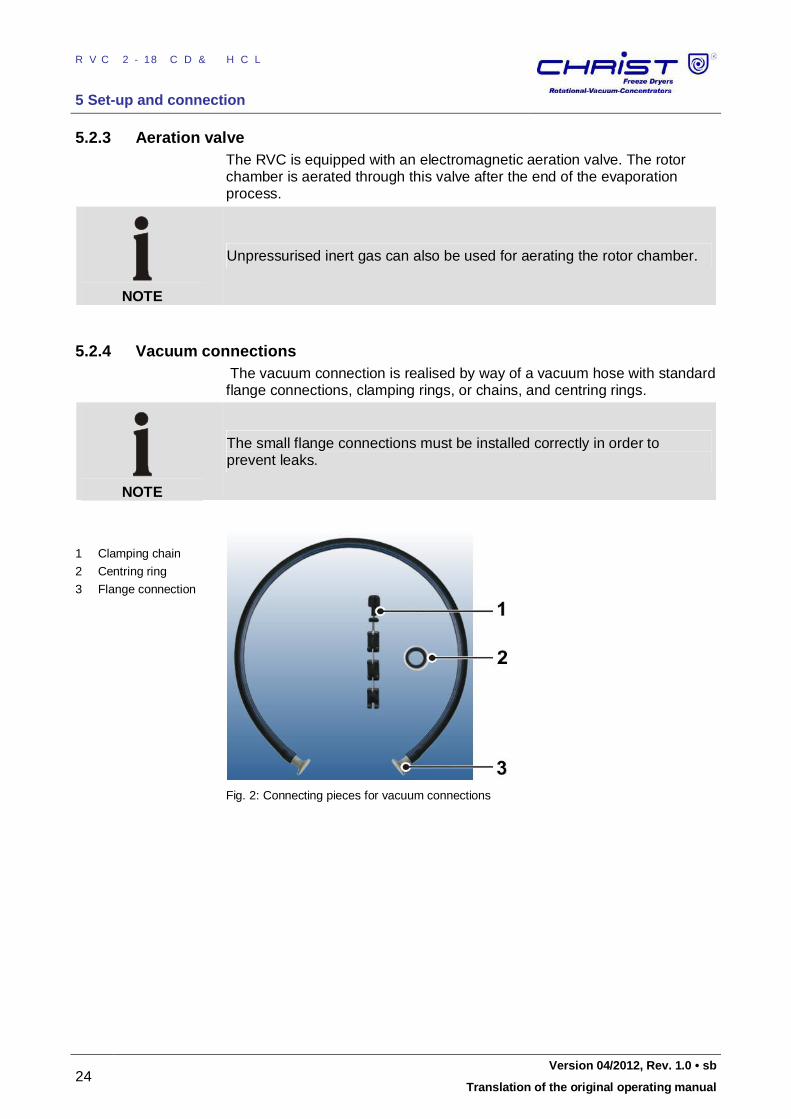
5.2.4 Vacuum connections The vacuum connection is realised by way of a vacuum hose with standard flange connections, clamping rings, or chains, and centring rings.
NOTE
The small flange connections must be installed correctly in order to prevent leaks.
1 Clamping chain
2 Centring ring
3 Flange connection
Fig. 2: Connecting pieces for vacuum connections
Pos: 91 / 010 Unive rsalm odul e/ Seit enwec hsel @ 0\m od_ 120 211 6244 312 _0. docx @ 10 5 @ @ 1
RVC 2-18 CD&HCL
5 Set-up and connection
Version 04/2012, Rev. 1.0 • sb 25
Translation of the original operating manual
Pos: 92 / 200 Christ /36 0 RVC-BA (STANDARDM ODULE)/ 050 Au fstellu ng u nd Ans chluss/ 050 -00 50 A nschluss von V akuu mpu mp e un d/od er Kü hlfalle @ 8\ mod _13 093 374 3944 3_6 8.d ocx @ 466 77 @ 2 @ 1
5.3 Connection of a vacuum pump and/or a cooling trap In order to withdraw and condense the vapours that are formed, the RVC can be connected with further components.
Pos: 93 / 010 Unive rsalm odul e/ L ee rzeile @ 0\ mod _120 211 624 450 0_0. docx @ 11 4 @ @ 1
Pos: 94 / 200 Christ /36 1 RVC-BA (PROJEKTE) /RVC 2-1 8 CDpl us_2 -18 CD plus_HCl /050 Aufstell ung und Anschluss /05 0-0 050 -00 11 BASIC: Ab pum pen übe r ei ne Vak uum pum pe_HC L @ 12\ mod_ 133 525 318 202 0_6 8.docx @ 6 399 1 @ 3 @ 1
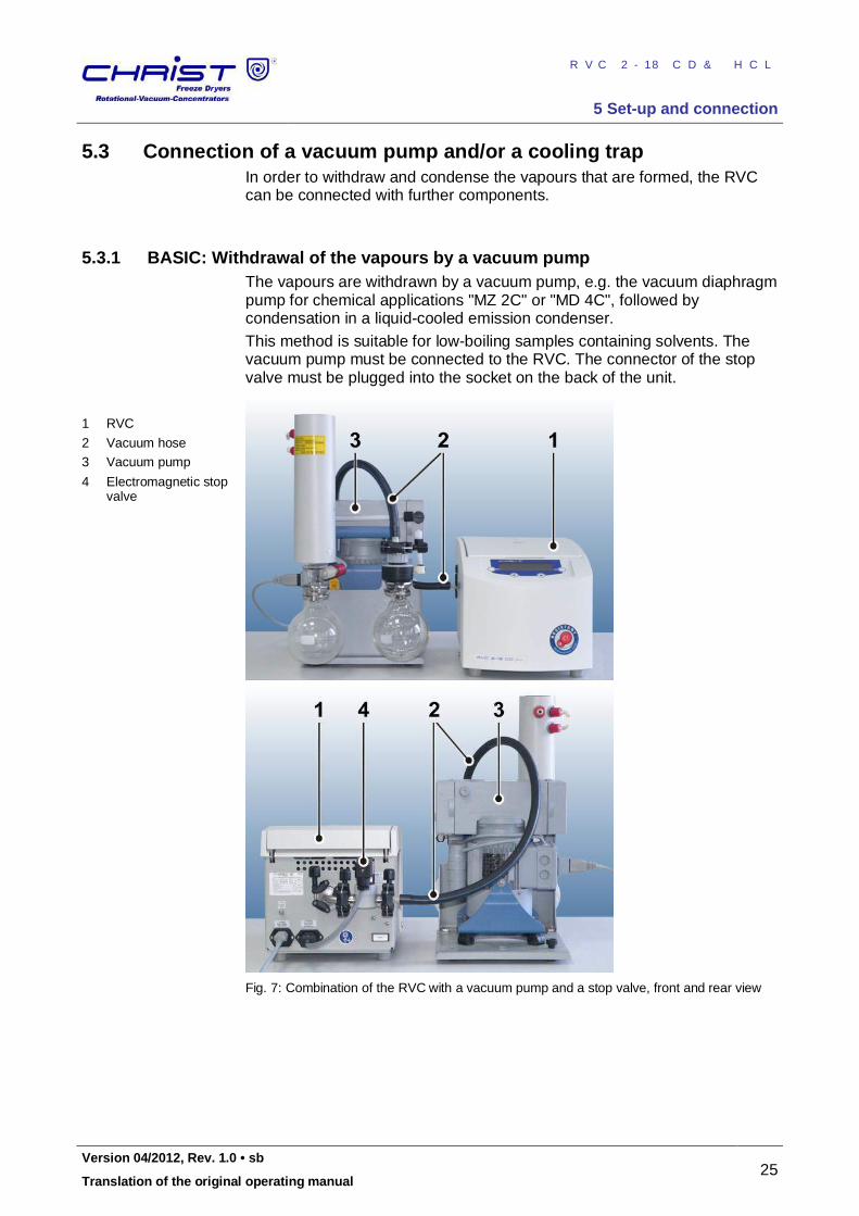
5.3.1 BASIC: Withdrawal of the vapours by a vacuum pump The vapours are withdrawn by a vacuum pump, e.g. the vacuum diaphragm pump for chemical applications "MZ 2C" or "MD 4C", followed by condensation in a liquid-cooled emission condenser. This method is suitable for low-boiling samples containing solvents. The vacuum pump must be connected to the RVC. The connector of the stop valve must be plugged into the socket on the back of the unit.
1 RVC
2 Vacuum hose
3 Vacuum pump
4 Electromagnetic stop valve
Fig. 7: Combination of the RVC with a vacuum pump and a stop valve, front and rear view
Pos: 95 / 010 Unive rsalm odul e/ Seit enwec hsel @ 0\m od_ 120 211 6244 312 _0. docx @ 10 5 @ @ 1
RVC 2-18 CD&HCL
5 Set-up and connection
26 Version 04/2012, Rev. 1.0 • sb
Translation of the original operating manual
Pos: 96 / 200 Christ /36 1 RVC-BA (PROJEKTE) /RVC 2-1 8 CDpl us_2 -18 CD plus_HCl /050 Aufstell ung und Anschluss /05 0-0 050 -00 21 S TANDARD: Kond ensa tion übe r ein e Kühlf alle_HCl @ 12\ mod _13 352 559 377 47_ 68.d ocx @ 639 99 @ 3 @ 1
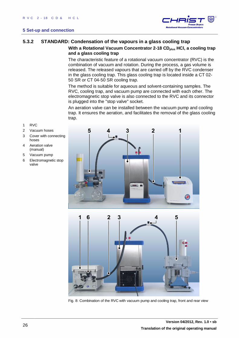
5.3.2 STANDARD: Condensation of the vapours in a glass cooling trap With a Rotational Vacuum Concentrator 2-18 CDplus HCl, a cooling trap and a glass cooling trap The characteristic feature of a rotational vacuum concentrator (RVC) is the combination of vacuum and rotation. During the process, a gas volume is released. The released vapours that are carried off by the RVC condenser in the glass cooling trap. This glass cooling trap is located inside a CT 02-50 SR or CT 04-50 SR cooling trap. The method is suitable for aqueous and solvent-containing samples. The RVC, cooling trap, and vacuum pump are connected with each other. The electromagnetic stop valve is also connected to the RVC and its connector is plugged into the "stop valve" socket. An aeration valve can be installed between the vacuum pump and cooling trap. It ensures the aeration, and facilitates the removal of the glass cooling trap.
1 RVC
2 Vacuum hoses
3 Cover with connecting hoses
4 Aeration valve (manual)
5 Vacuum pump
6 Electromagnetic stop valve
Fig. 8: Combination of the RVC with vacuum pump and cooling trap, front and rear view
Pos: 97 / 010 Unive rsalm odul e/ Seit enwec hsel @ 0\m od_ 120 211 6244 312 _0. docx @ 10 5 @ @ 1
RVC 2-18 CD&HCL
5 Set-up and connection
Version 04/2012, Rev. 1.0 • sb 27
Translation of the original operating manual
Pos: 98 / 200 Christ /36 1 RVC-BA (PROJEKTE) /RVC 2-1 8 CDpl us_2 -18 CD plus_HCl /050 Aufstell ung und Anschluss /05 0-0 050 -00 30 PRO FESSIONAL: Ko nden satio n üb er eine Kü hlfalle mit Ve rteile rblock @ 1 2\mo d_1 335 260 055 746 _68. docx @ 64 007 @ 3 @ 1
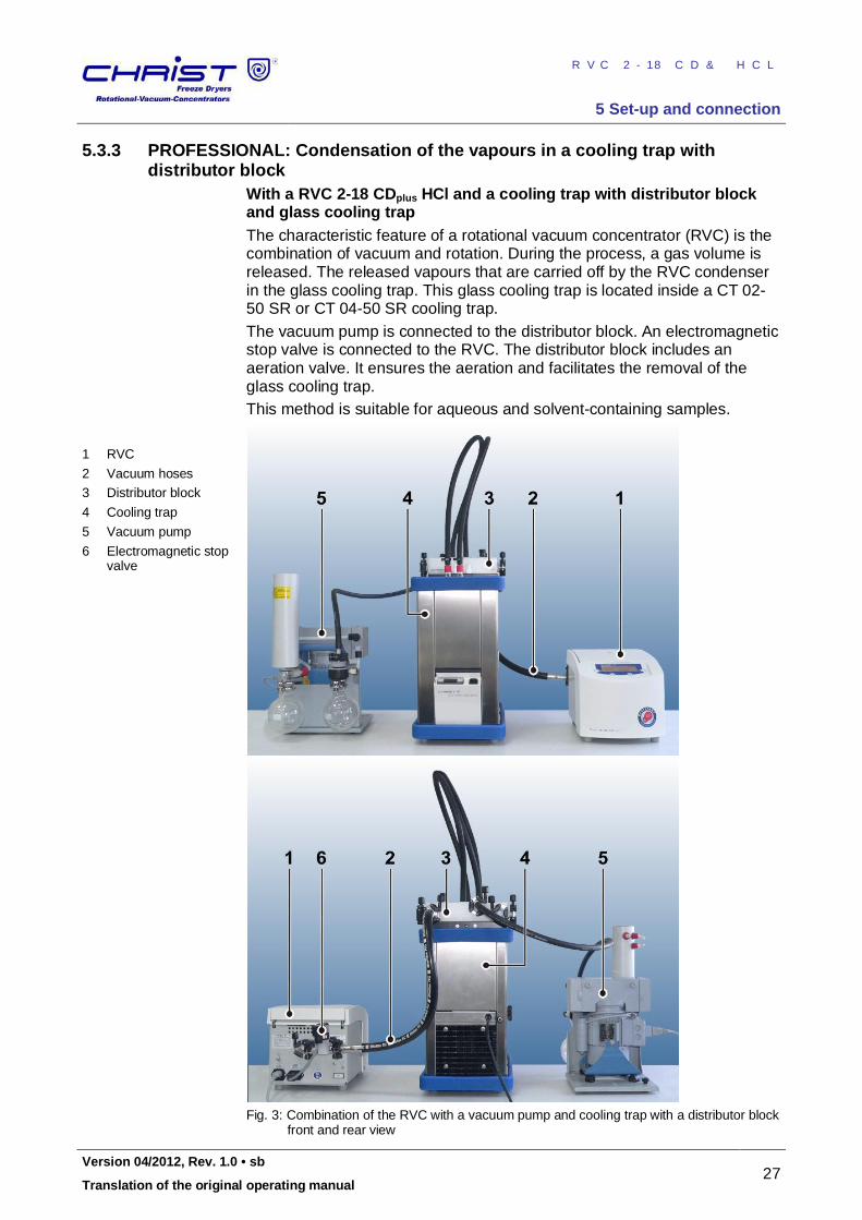
5.3.3 PROFESSIONAL: Condensation of the vapours in a cooling trap with distributor block
With a RVC 2-18 CDplus HCl and a cooling trap with distributor block and glass cooling trap The characteristic feature of a rotational vacuum concentrator (RVC) is the combination of vacuum and rotation. During the process, a gas volume is released. The released vapours that are carried off by the RVC condenser in the glass cooling trap. This glass cooling trap is located inside a CT 02-50 SR or CT 04-50 SR cooling trap. The vacuum pump is connected to the distributor block. An electromagnetic stop valve is connected to the RVC. The distributor block includes an aeration valve. It ensures the aeration and facilitates the removal of the glass cooling trap. This method is suitable for aqueous and solvent-containing samples.
1 RVC
2 Vacuum hoses
3 Distributor block
4 Cooling trap
5 Vacuum pump
6 Electromagnetic stop valve
Fig. 3: Combination of the RVC with a vacuum pump and cooling trap with a distributor block front and rear view
Pos: 99 / 010 Unive rsalm odul e/ Seit enwec hsel @ 0\m od_ 120 211 6244 312 _0. docx @ 10 5 @ @ 1
RVC 2-18 CD&HCL
5 Set-up and connection
28 Version 04/2012, Rev. 1.0 • sb
Translation of the original operating manual
Pos: 100 /20 0 Ch rist/3 61 RVC-BA (PROJEK TE)/RVC 2- 18 CD plus_ 2-1 8 CDplus _HCl/05 0 Aufst ellun g un d Anschl uss/0 50- 005 0-0 040 PROFESSIONAL TWIN: Ko nde nsatio n üb er eine Kü hlfalle mit zw ei RVC HCl @ 1 2\m od_ 133 533 260 035 7_68 .docx @ 6 402 1 @ 3 @ 1
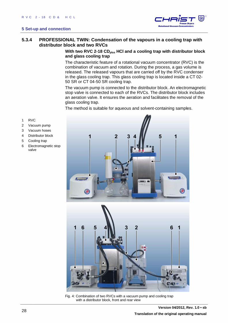
5.3.4 PROFESSIONAL TWIN: Condensation of the vapours in a cooling trap with distributor block and two RVCs
With two RVC 2-18 CDplus HCl and a cooling trap with distributor block and glass cooling trap The characteristic feature of a rotational vacuum concentrator (RVC) is the combination of vacuum and rotation. During the process, a gas volume is released. The released vapours that are carried off by the RVC condenser in the glass cooling trap. This glass cooling trap is located inside a CT 02-50 SR or CT 04-50 SR cooling trap. The vacuum pump is connected to the distributor block. An electromagnetic stop valve is connected to each of the RVCs. The distributor block includes an aeration valve. It ensures the aeration and facilitates the removal of the glass cooling trap. The method is suitable for aqueous and solvent-containing samples.
1 RVC
2 Vacuum pump
3 Vacuum hoses
4 Distributor block
5 Cooling trap
6 Electromagnetic stop valve
Fig. 4: Combination of two RVCs with a vacuum pump and cooling trap with a distributor block, front and rear view
Pos: 101 /01 0 Univ ersal mod ule/ Ab schnitt swechs el @ 0 \mo d_1 202 124 514 062_ 0.d ocx @ 418 @ @ 1
RVC 2-18 CD&HCL
6 Operation
Version 04/2012, Rev. 1.0 • sb 29
Translation of the original operating manual
Pos: 102 /01 0 Univ ersal mod ule/ Sei tenwe chsel @ 0\ mod _12 021 1624 431 2_0 .docx @ 1 05 @ @ 1 Pos: 103 /20 0 Ch rist/3 60 RVC-BA (S TANDARDMODULE) /06 0 Betri eb/0 60 Bet rieb == == === == == === == == === == == === == == == === == = @ 8\mo d_1 309 426 563 173 _68. docx @ 46 735 @ 1 @ 1
6 Operation Pos: 104 /20 0 Ch rist/3 60 RVC-BA (S TANDARDMODULE) /06 0 Betri eb/0 60- 001 0 Ers te In bet rieb nah me+ ++ ++ +++ ++ ++ +++ ++ ++ +++ ++ ++ @ 8\ mod _13 094 265 6354 8_6 8.d ocx @ 4674 3 @ 2 @ 1
6.1 Initial start-up
WARNING
Before the initial start-up, please ensure that your RVC is properly set up and installed (see chapter 5 - "Set-up and connection")
Pos: 105 /01 0 Univ ersal mod ule/ Lee rzeile @ 0\ mo d_12 021 162 445 00_ 0.doc x @ 1 14 @ @ 1
Pos: 106 /20 0 Ch rist/3 60 RVC-BA (S TANDARDMODULE) /06 0 Betri eb/0 60- 002 0 Einsc halte n+ +++ ++ ++ +++ ++ ++ +++ ++ ++ +++ ++ ++ ++ +++ ++ ++ @ 8\ mod _13 0942 656 454 8_6 8.doc x @ 4 676 7 @ 2 @ 1
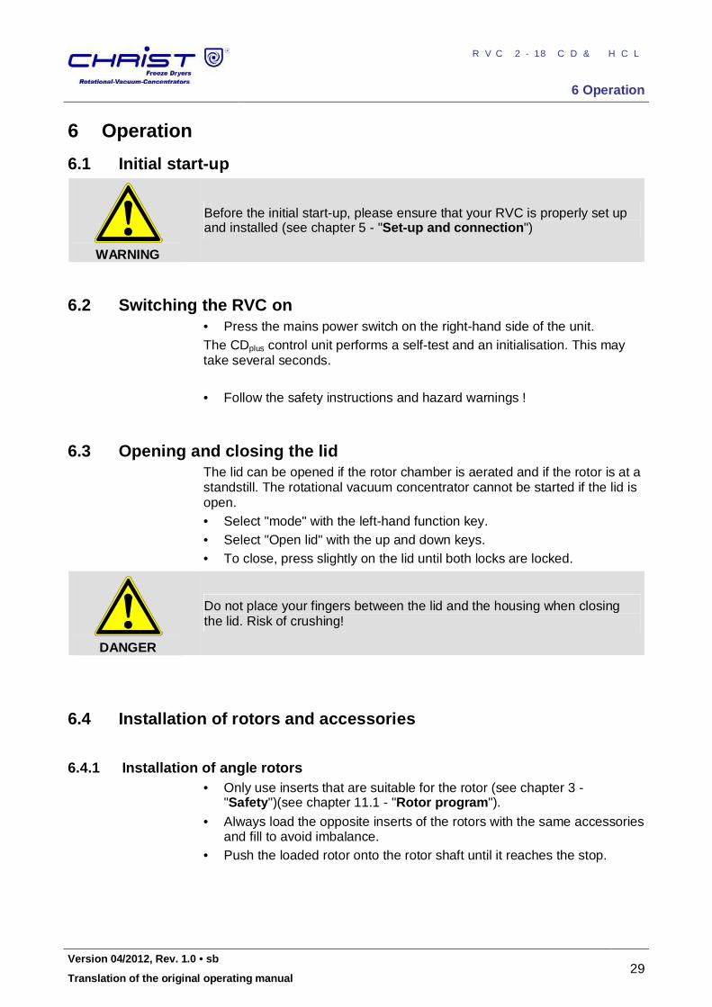
6.2 Switching the RVC on • Press the mains power switch on the right-hand side of the unit. The CDplus control unit performs a self-test and an initialisation. This may take several seconds. • Follow the safety instructions and hazard warnings !
Pos: 107 /01 0 Univ ersal mod ule/ Lee rzeile @ 0\ mo d_12 021 162 445 00_ 0.doc x @ 1 14 @ @ 1
Pos: 108 /20 0 Ch rist/3 60 RVC-BA (S TANDARDMODULE) /06 0 Betri eb/0 60- 003 0 Ö ffne n un d Schlie ßen des D eckels @ 8\ mod _13 094 270 445 54_6 8.d ocx @ 467 91 @ 2 @ 1
6.3 Opening and closing the lid The lid can be opened if the rotor chamber is aerated and if the rotor is at a standstill. The rotational vacuum concentrator cannot be started if the lid is open. • Select "mode" with the left-hand function key. • Select "Open lid" with the up and down keys. • To close, press slightly on the lid until both locks are locked.
DANGER
Do not place your fingers between the lid and the housing when closing the lid. Risk of crushing!
Pos: 109 /01 0 Univ ersal mod ule/ Lee rzeile @ 0\ mo d_12 021 162 445 00_ 0.doc x @ 1 14 @ @ 1
Pos: 110 /20 0 Ch rist/3 60 RVC-BA (S TANDARDMODULE) /06 0 Betri eb/0 60- 004 0 Eins etzen von R oto ren und Zu beh ör- -- --- -- --- --- -- --- -- --- -- --- --- -- --- - @ 8\m od_ 1309 498 541 224 _68. docx @ 46 808 @ 2 @ 1
6.4 Installation of rotors and accessories
Pos: 111 /20 0 Ch rist/3 60 RVC-BA (S TANDARDMODULE) /06 0 Betri eb/0 60- 004 0-0 010 Einsetz en v on Wink elrot ore n @ 8\m od_ 130 9496 686 889 _68. docx @ 46 801 @ 3 @ 1
6.4.1 Installation of angle rotors • Only use inserts that are suitable for the rotor (see chapter 3 -
"Safety")(see chapter 11.1 - "Rotor program").
• Always load the opposite inserts of the rotors with the same accessories and fill to avoid imbalance.
• Push the loaded rotor onto the rotor shaft until it reaches the stop.
RVC 2-18 CD&HCL
6 Operation
30 Version 04/2012, Rev. 1.0 • sb
Translation of the original operating manual
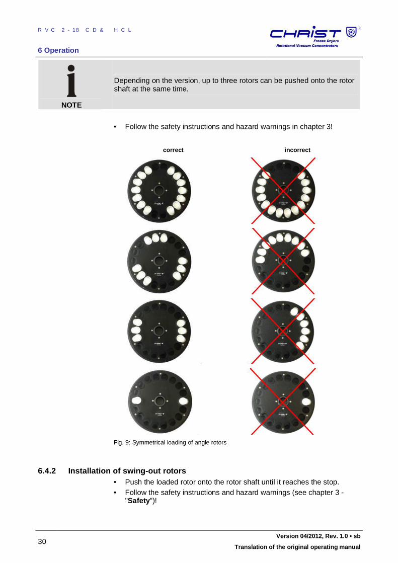
NOTE
Depending on the version, up to three rotors can be pushed onto the rotor shaft at the same time.
• Follow the safety instructions and hazard warnings in chapter 3!
correct incorrect
Fig. 9: Symmetrical loading of angle rotors Pos: 112 /01 0 Univ ersal mod ule/ Lee rzeile @ 0\ mo d_12 021 162 445 00_ 0.doc x @ 1 14 @ @ 1
Pos: 113 /20 0 Ch rist/3 60 RVC-BA (S TANDARDMODULE) /06 0 Betri eb/0 60- 004 0-0 020 Einsetz en v on Aussc hwing rot ore n @ 8 \mo d_1 309 498 6385 52_ 68. docx @ 468 15 @ 3 @ 1
6.4.2 Installation of swing-out rotors • Push the loaded rotor onto the rotor shaft until it reaches the stop. • Follow the safety instructions and hazard warnings (see chapter 3 -
"Safety")! Pos: 114 /01 0 Univ ersal mod ule/ Sei tenwe chsel @ 0\ mod _12 021 1624 431 2_0 .docx @ 1 05 @ @ 1
RVC 2-18 CD&HCL
6 Operation
Version 04/2012, Rev. 1.0 • sb 31
Translation of the original operating manual
Pos: 115 /20 0 Ch rist/3 60 RVC-BA (S TANDARDMODULE) /06 0 Betri eb/0 60- 004 0-0 030 Einsetz en v on Zub ehö r @ 8 \mo d_1 309 508 120 119 _68. docx @ 46 850 @ 3 @ 1
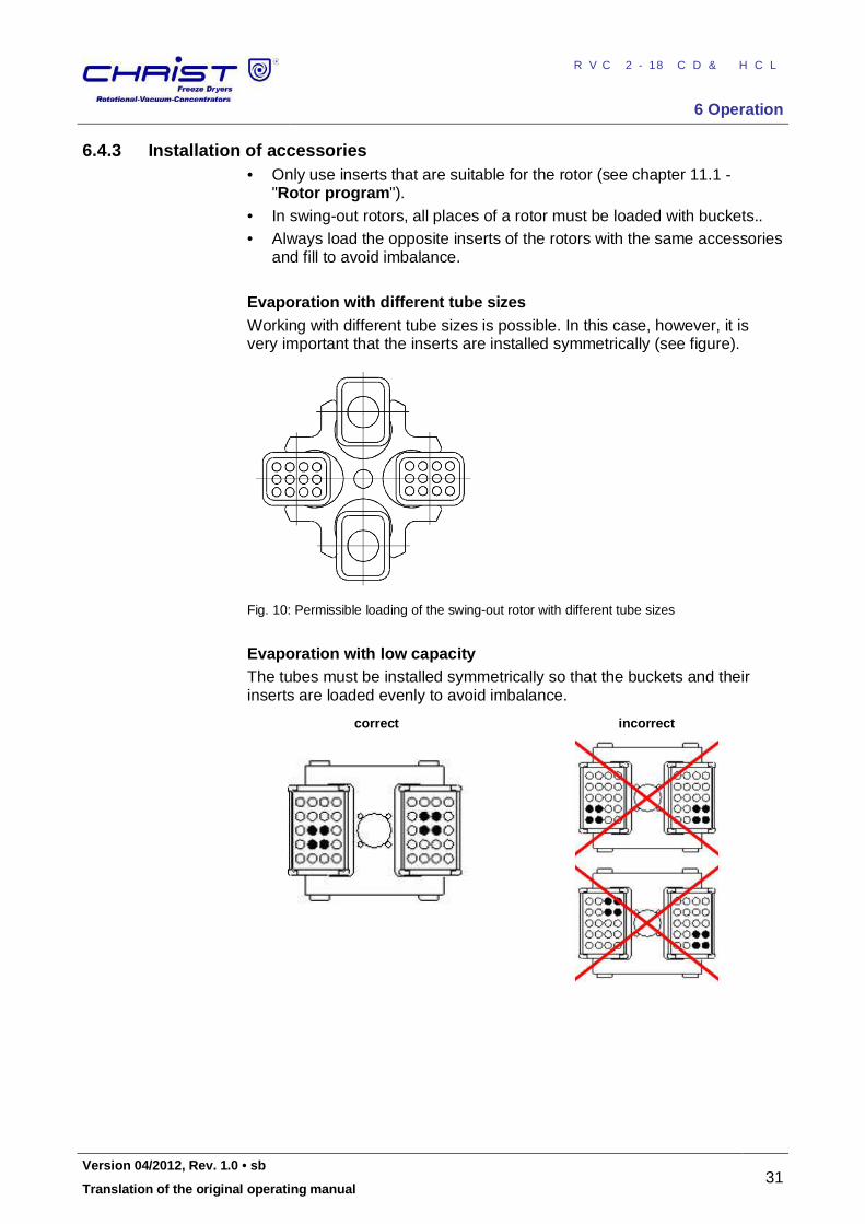
6.4.3 Installation of accessories • Only use inserts that are suitable for the rotor (see chapter 11.1 -
"Rotor program"). • In swing-out rotors, all places of a rotor must be loaded with buckets.. • Always load the opposite inserts of the rotors with the same accessories
and fill to avoid imbalance. Evaporation with different tube sizes Working with different tube sizes is possible. In this case, however, it is very important that the inserts are installed symmetrically (see figure).
Fig. 10: Permissible loading of the swing-out rotor with different tube sizes
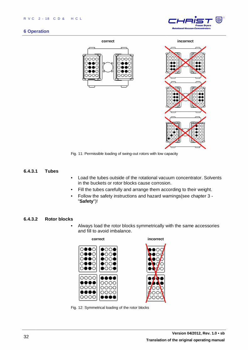
Evaporation with low capacity The tubes must be installed symmetrically so that the buckets and their inserts are loaded evenly to avoid imbalance.
correct incorrect
RVC 2-18 CD&HCL
6 Operation
32 Version 04/2012, Rev. 1.0 • sb
Translation of the original operating manual
correct incorrect
Fig. 11: Permissible loading of swing-out rotors with low capacity Pos: 116 /01 0 Univ ersal mod ule/ Lee rzeile @ 0\ mo d_12 021 162 445 00_ 0.doc x @ 1 14 @ @ 1
Pos: 117 /20 0 Ch rist/3 60 RVC-BA (S TANDARDMODULE) /06 0 Betri eb/0 60- 004 0-0 030 -00 10 Gefä ße @ 8\ mod _13 094 988 287 79_ 68.d ocx @ 468 22 @ 4 @ 1
6.4.3.1 Tubes • Load the tubes outside of the rotational vacuum concentrator. Solvents
in the buckets or rotor blocks cause corrosion. • Fill the tubes carefully and arrange them according to their weight. • Follow the safety instructions and hazard warnings(see chapter 3 -
"Safety")! Pos: 118 /01 0 Univ ersal mod ule/ Lee rzeile @ 0\ mo d_12 021 162 445 00_ 0.doc x @ 1 14 @ @ 1
Pos: 119 /20 0 Ch rist/3 60 RVC-BA (S TANDARDMODULE) /06 0 Betri eb/0 60- 004 0-0 030 -00 20 A ufna hme blöcke @ 8\ mo d_1 3094 990 493 32_ 68.d ocx @ 468 29 @ 4 @ 1
6.4.3.2 Rotor blocks • Always load the rotor blocks symmetrically with the same accessories
and fill to avoid imbalance.
correct incorrect
Fig. 12: Symmetrical loading of the rotor blocks Pos: 120 /01 0 Univ ersal mod ule/ Lee rzeile @ 0\ mo d_12 021 162 445 00_ 0.doc x @ 1 14 @ @ 1
Pos: 121 /20 0 Ch rist/3 60 RVC-BA (S TANDARDMODULE) /06 0 Betri eb/0 60- 004 0-0 030 -00 30 B eche r @ 8 \mo d_1 309 500 943 610 _68. docx @ 46 836 @ 4 @ 1
RVC 2-18 CD&HCL
6 Operation
Version 04/2012, Rev. 1.0 • sb 33
Translation of the original operating manual
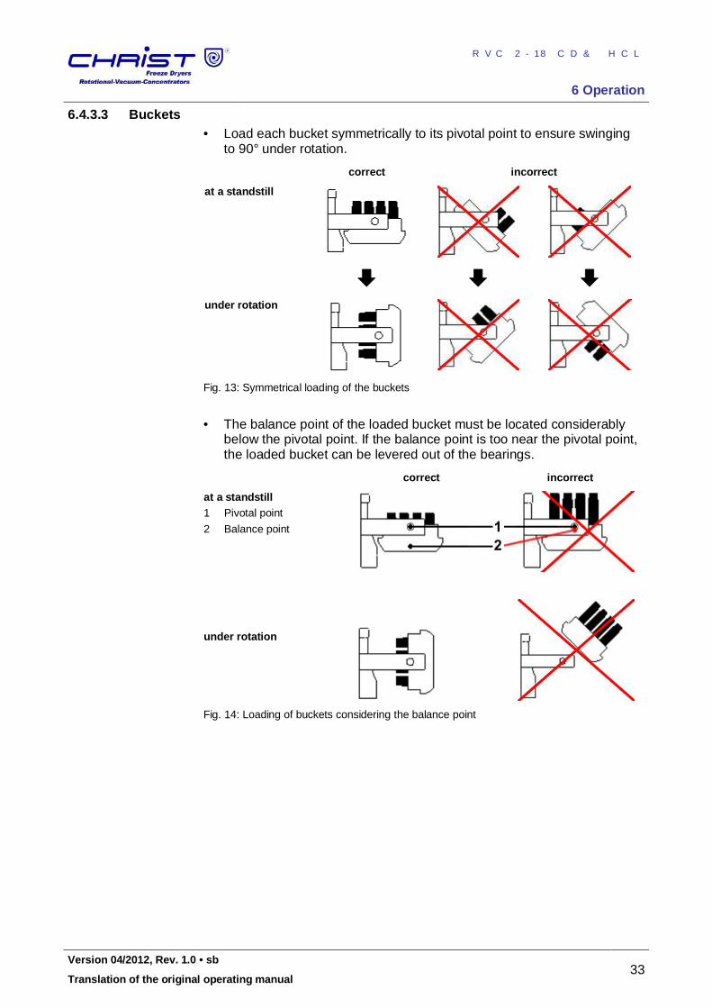
6.4.3.3 Buckets • Load each bucket symmetrically to its pivotal point to ensure swinging
to 90° under rotation.
correct incorrect
at a standstill
under rotation
Fig. 13: Symmetrical loading of the buckets
• The balance point of the loaded bucket must be located considerably
below the pivotal point. If the balance point is too near the pivotal point, the loaded bucket can be levered out of the bearings.
correct incorrect
at a standstill 1 Pivotal point
2 Balance point
under rotation
Fig. 14: Loading of buckets considering the balance point Pos: 122 /01 0 Univ ersal mod ule/ Sei tenwe chsel @ 0\ mod _12 021 1624 431 2_0 .docx @ 1 05 @ @ 1
RVC 2-18 CD&HCL
6 Operation
34 Version 04/2012, Rev. 1.0 • sb
Translation of the original operating manual
Pos: 123 /20 0 Ch rist/3 60 RVC-BA (S TANDARDMODULE) /06 0 Betri eb/CDpl us/06 0- 0050 CDpl us Anlag enst eue run g-- -- --- --- -- --- -- --- --- -- --- -- --- -- --- --- -- -- @ 8\m od_ 130 950 863 486 7_6 8.docx @ 4 685 6 @ 2 @ 1
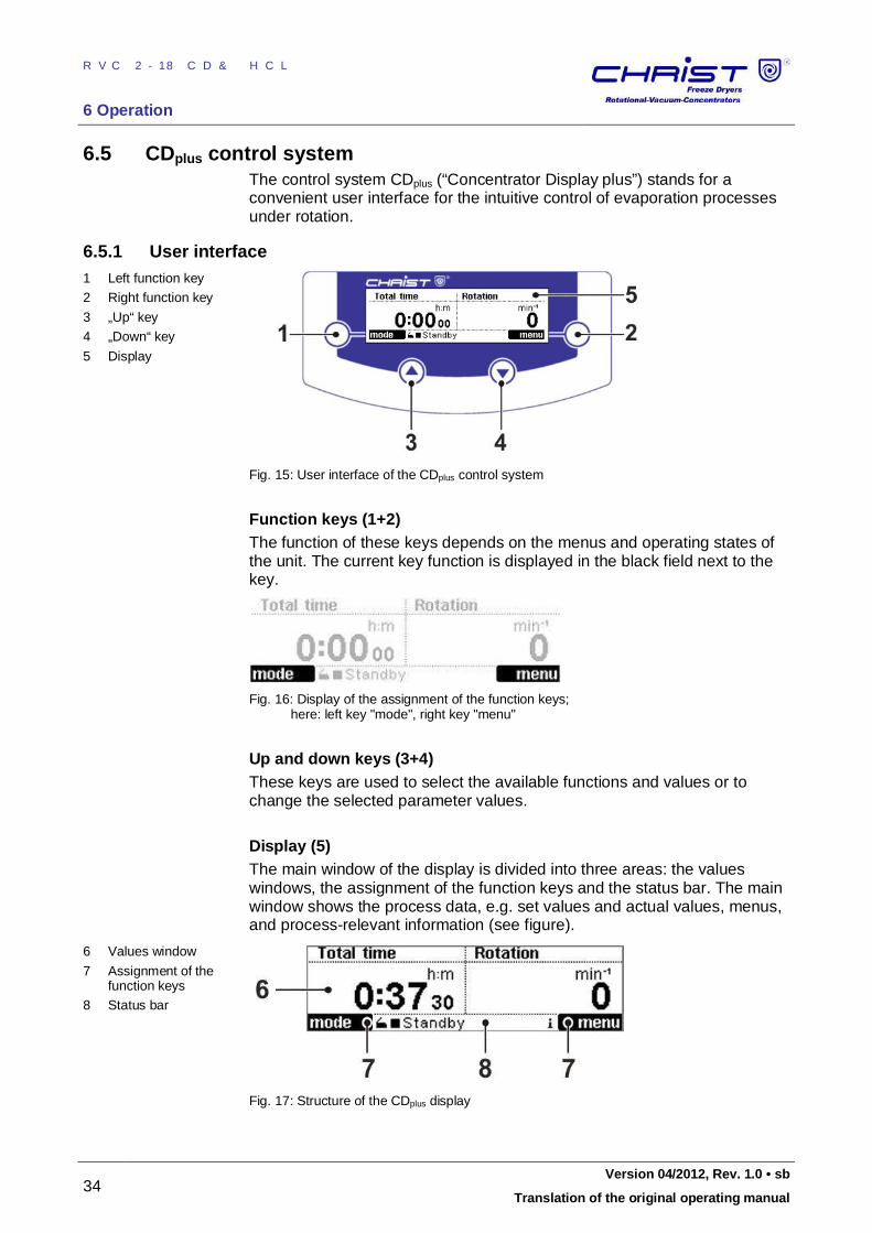
6.5 CDplus control system The control system CDplus (“Concentrator Display plus”) stands for a convenient user interface for the intuitive control of evaporation processes under rotation.
Pos: 124 /20 0 Ch rist/3 61 RVC-BA (PROJEK TE)/RVC 2- 18 CD plus_ 2-1 8 CDplus _HCl/06 0 Bet rieb/ 060 -00 50- 001 0 Bedi eno berfl äche RVC 2- 18 CDpl us @ 9\m od_1 320 906 300 798 _68. docx @ 54 100 @ 3 @ 1
6.5.1 User interface 1 Left function key
2 Right function key
3 „Up“ key
4 „Down“ key
5 Display
Fig. 15: User interface of the CDplus control system
Function keys (1+2) The function of these keys depends on the menus and operating states of the unit. The current key function is displayed in the black field next to the key.
Fig. 16: Display of the assignment of the function keys; here: left key "mode", right key "menu"
Up and down keys (3+4) These keys are used to select the available functions and values or to change the selected parameter values. Display (5) The main window of the display is divided into three areas: the values windows, the assignment of the function keys and the status bar. The main window shows the process data, e.g. set values and actual values, menus, and process-relevant information (see figure).
6 Values window
7 Assignment of the function keys
8 Status bar
Fig. 17: Structure of the CDplus display
RVC 2-18 CD&HCL
6 Operation
Version 04/2012, Rev. 1.0 • sb 35
Translation of the original operating manual
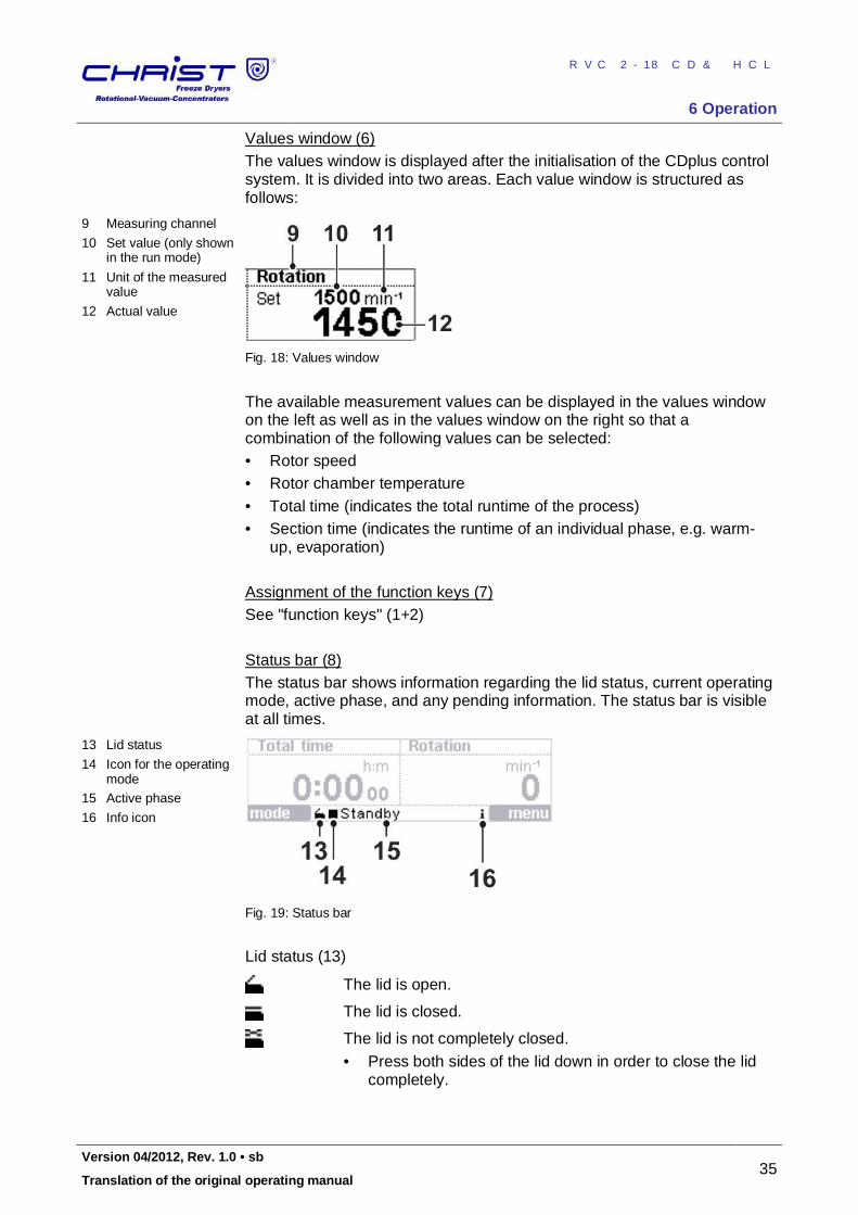
Values window (6) The values window is displayed after the initialisation of the CDplus control system. It is divided into two areas. Each value window is structured as follows:
9 Measuring channel
10 Set value (only shown in the run mode)
11 Unit of the measured value
12 Actual value
Fig. 18: Values window
The available measurement values can be displayed in the values window on the left as well as in the values window on the right so that a combination of the following values can be selected: • Rotor speed • Rotor chamber temperature • Total time (indicates the total runtime of the process) • Section time (indicates the runtime of an individual phase, e.g. warm-
up, evaporation) Assignment of the function keys (7) See "function keys" (1+2) Status bar (8) The status bar shows information regarding the lid status, current operating mode, active phase, and any pending information. The status bar is visible at all times.
13 Lid status
14 Icon for the operating mode
15 Active phase
16 Info icon
Fig. 19: Status bar
Lid status (13)
The lid is open.
The lid is closed.
The lid is not completely closed. • Press both sides of the lid down in order to close the lid
completely.
RVC 2-18 CD&HCL
6 Operation
36 Version 04/2012, Rev. 1.0 • sb
Translation of the original operating manual
Operating mode (14)
The rotational vacuum concentrator is in the standby mode. All aggregates are switched off.
The rotational vacuum concentrator is in the run mode. The timer is deactivated.
The rotational vacuum concentrator is in the run mode. The timer is activated.
Active phases (15)
Open lid The rotor is at a standstill, and the lid can be opened.
Warm-up The vacuum pump and/or the cooling trap are in the warm-up phase.
Evaporation manual
The RVC is in a manual-controlled evaporation run.
Pending information (16)
If any messages are pending, the info icon flashes every second to draw the user's attention to error messages, process messages, or general information concerning the process or the unit. The messages can be displayed in the process and equipment information window (see chapter 6.5.3.2 - "Process and equipment information")
Pos: 125 /01 0 Univ ersal mod ule/ Lee rzeile @ 0\ mo d_12 021 162 445 00_ 0.doc x @ 1 14 @ @ 1
Pos: 126 /20 0 Ch rist/3 61 RVC-BA (PROJEK TE)/RVC 2- 18 CD plus_ 2-1 8 CDplus _HCl/06 0 Bet rieb/ 060 -00 50- 002 0 Modu s RVC 2- 18 CDpl us @ 9\m od_ 132 0906 427 497 _68. docx @ 54 108 @ 3 @ 1
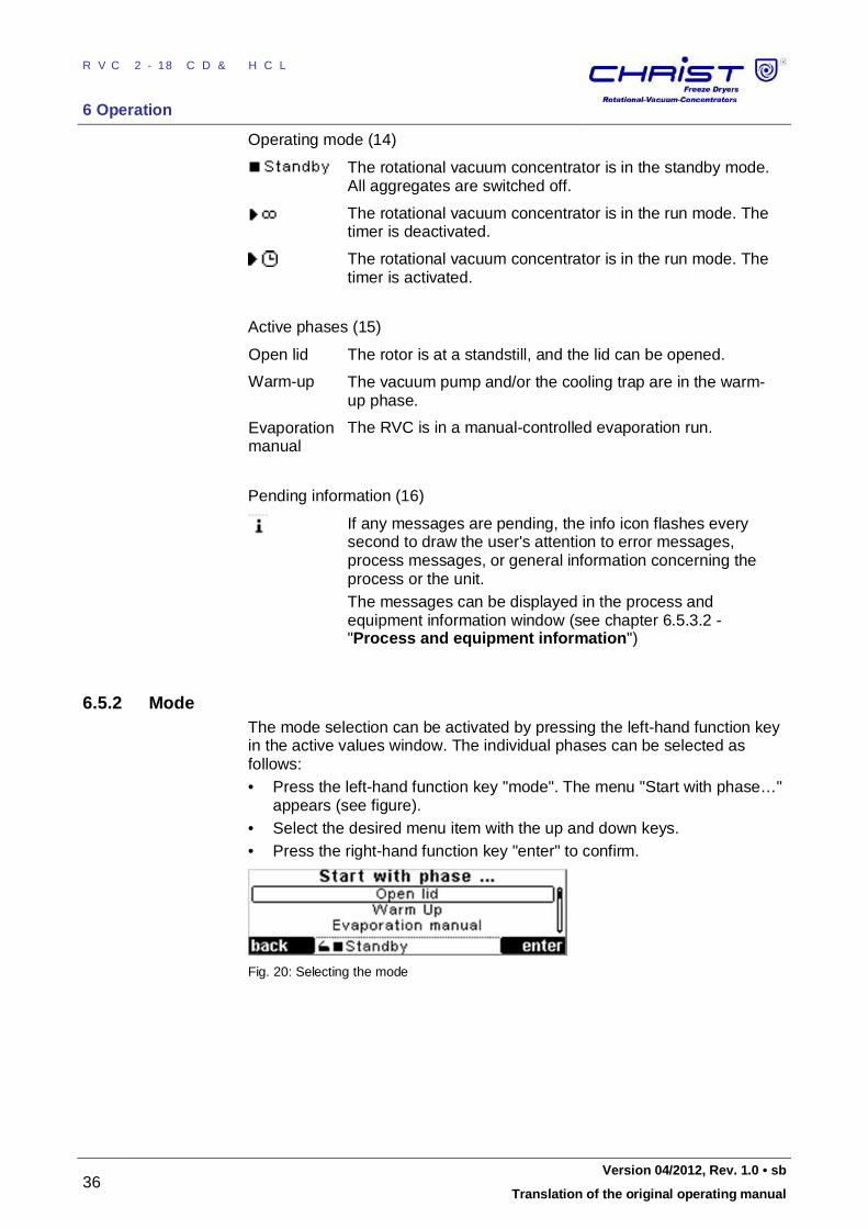
6.5.2 Mode The mode selection can be activated by pressing the left-hand function key in the active values window. The individual phases can be selected as follows: • Press the left-hand function key "mode". The menu "Start with phase…"
appears (see figure). • Select the desired menu item with the up and down keys. • Press the right-hand function key "enter" to confirm.
Fig. 20: Selecting the mode
RVC 2-18 CD&HCL
6 Operation
Version 04/2012, Rev. 1.0 • sb 37
Translation of the original operating manual
Opening the lid The lid can only be opened if the rotor is at a standstill. It is not possible to open the lid during an evaporation process
DANGER
During the evaporation process, the housing, lid and interior of the rotational vacuum concentrator can reach surface temperatures of more than +50°C. Risk of burns!
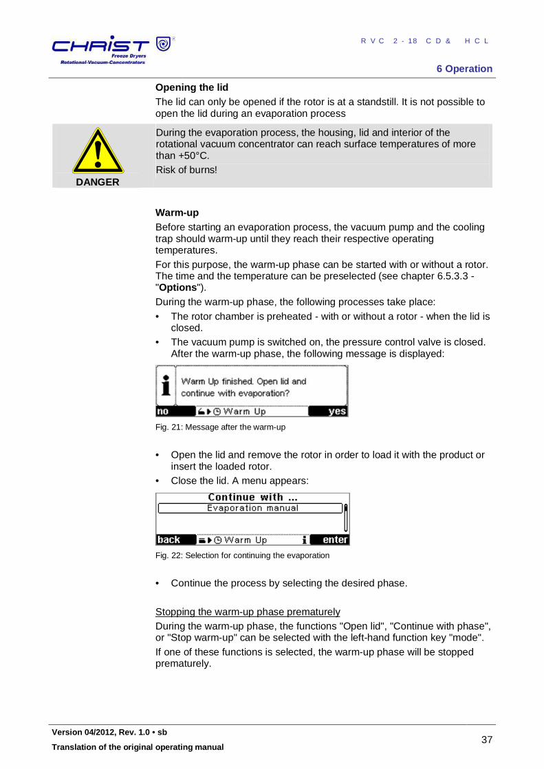
Warm-up Before starting an evaporation process, the vacuum pump and the cooling trap should warm-up until they reach their respective operating temperatures. For this purpose, the warm-up phase can be started with or without a rotor. The time and the temperature can be preselected (see chapter 6.5.3.3 - "Options"). During the warm-up phase, the following processes take place: • The rotor chamber is preheated - with or without a rotor - when the lid is
closed. • The vacuum pump is switched on, the pressure control valve is closed.
After the warm-up phase, the following message is displayed:
Fig. 21: Message after the warm-up
• Open the lid and remove the rotor in order to load it with the product or
insert the loaded rotor. • Close the lid. A menu appears:
Fig. 22: Selection for continuing the evaporation
• Continue the process by selecting the desired phase. Stopping the warm-up phase prematurely During the warm-up phase, the functions "Open lid", "Continue with phase", or "Stop warm-up" can be selected with the left-hand function key "mode". If one of these functions is selected, the warm-up phase will be stopped prematurely.
RVC 2-18 CD&HCL
6 Operation
38 Version 04/2012, Rev. 1.0 • sb
Translation of the original operating manual
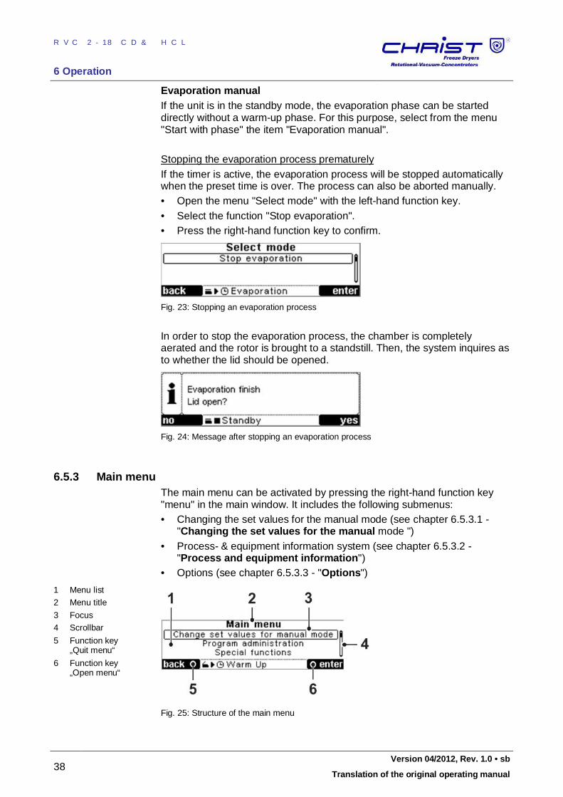
Evaporation manual If the unit is in the standby mode, the evaporation phase can be started directly without a warm-up phase. For this purpose, select from the menu "Start with phase" the item "Evaporation manual". Stopping the evaporation process prematurely If the timer is active, the evaporation process will be stopped automatically when the preset time is over. The process can also be aborted manually. • Open the menu "Select mode" with the left-hand function key. • Select the function "Stop evaporation". • Press the right-hand function key to confirm.
Fig. 23: Stopping an evaporation process
In order to stop the evaporation process, the chamber is completely aerated and the rotor is brought to a standstill. Then, the system inquires as to whether the lid should be opened.
Fig. 24: Message after stopping an evaporation process
Pos: 127 /01 0 Univ ersal mod ule/ Lee rzeile @ 0\ mo d_12 021 162 445 00_ 0.doc x @ 1 14 @ @ 1
Pos: 128 /20 0 Ch rist/3 61 RVC-BA (PROJEK TE)/RVC 2- 18 CD plus_ 2-1 8 CDplus _HCl/06 0 Bet rieb/ 060 -00 50- 003 0 Ha upt men ü RVC 2- 18 CD plus @ 9\m od_ 132 0906 561 695 _68 .docx @ 54 117 @ 3 @ 1
6.5.3 Main menu The main menu can be activated by pressing the right-hand function key "menu" in the main window. It includes the following submenus: • Changing the set values for the manual mode (see chapter 6.5.3.1 -
"Changing the set values for the manual mode ") • Process- & equipment information system (see chapter 6.5.3.2 -
"Process and equipment information") • Options (see chapter 6.5.3.3 - "Options")
1 Menu list
2 Menu title
3 Focus
4 Scrollbar
5 Function key „Quit menu“
6 Function key „Open menu“
Fig. 25: Structure of the main menu Pos: 129 /20 0 Ch rist/3 61 RVC-BA (PROJEK TE)/RVC 2- 18 CD plus_ 2-1 8 CDplus _HCl/06 0 Bet rieb/ 060 -00 50- 003 0-0 010 Sollwer te fü r M anu ellmo dus änd ern RVC 2-1 8 CDplus @ 9 \mo d_1 320 9066 423 87_ 68.d ocx @ 541 24 @ 4 @ 1
RVC 2-18 CD&HCL
6 Operation
Version 04/2012, Rev. 1.0 • sb 39
Translation of the original operating manual
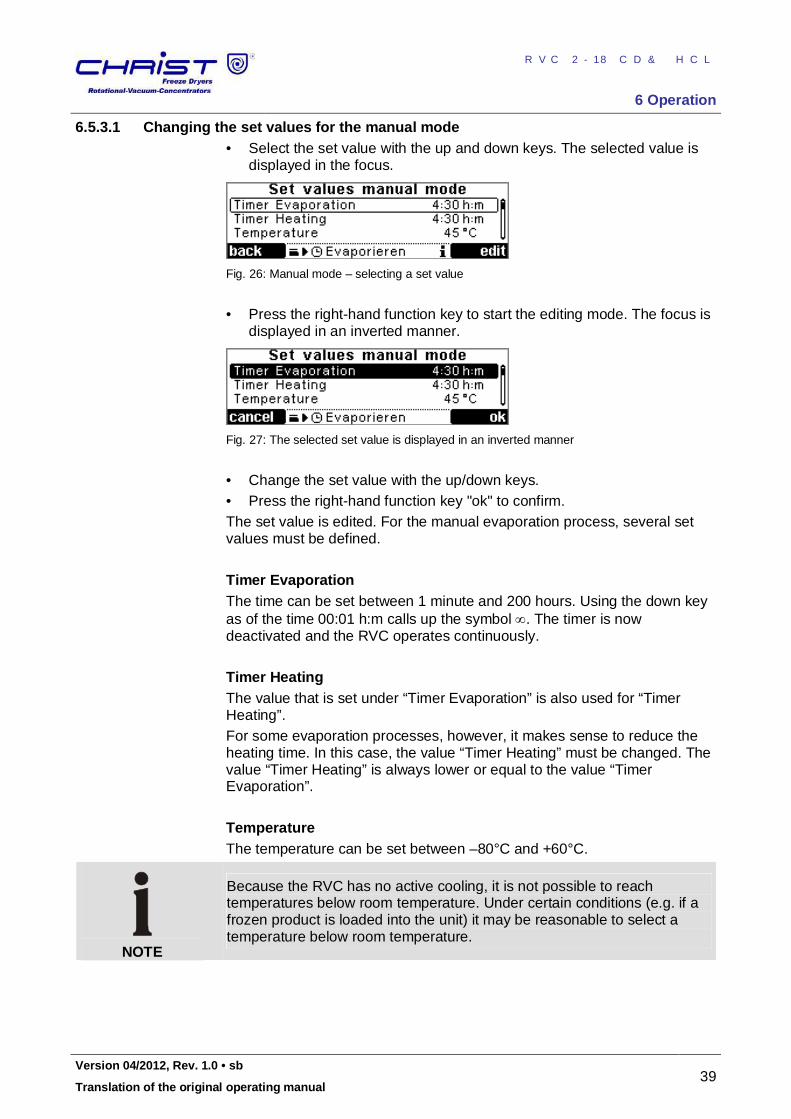
6.5.3.1 Changing the set values for the manual mode • Select the set value with the up and down keys. The selected value is
displayed in the focus.
Fig. 26: Manual mode – selecting a set value
• Press the right-hand function key to start the editing mode. The focus is
displayed in an inverted manner.
Fig. 27: The selected set value is displayed in an inverted manner
• Change the set value with the up/down keys. • Press the right-hand function key "ok" to confirm. The set value is edited. For the manual evaporation process, several set values must be defined. Timer Evaporation The time can be set between 1 minute and 200 hours. Using the down key as of the time 00:01 h:m calls up the symbol . The timer is now deactivated and the RVC operates continuously. Timer Heating The value that is set under “Timer Evaporation” is also used for “Timer Heating”. For some evaporation processes, however, it makes sense to reduce the heating time. In this case, the value “Timer Heating” must be changed. The value “Timer Heating” is always lower or equal to the value “Timer Evaporation”. Temperature The temperature can be set between –80°C and +60°C.
NOTE
Because the RVC has no active cooling, it is not possible to reach temperatures below room temperature. Under certain conditions (e.g. if a frozen product is loaded into the unit) it may be reasonable to select a temperature below room temperature.
Pos: 130 /01 0 Univ ersal mod ule/ Sei tenwe chsel @ 0\ mod _12 021 1624 431 2_0 .docx @ 1 05 @ @ 1
RVC 2-18 CD&HCL
6 Operation
40 Version 04/2012, Rev. 1.0 • sb
Translation of the original operating manual
Pos: 131 /20 0 Ch rist/3 60 RVC-BA (S TANDARDMODULE) /06 0 Betri eb/CDpl us/06 0- 0050 -00 30 -004 0 Pr ozess - un d Anla gen -Inf orm ation en @ 8\ mod _130 993 318 443 3_6 8.doc x @ 4 711 5 @ 4 @ 1
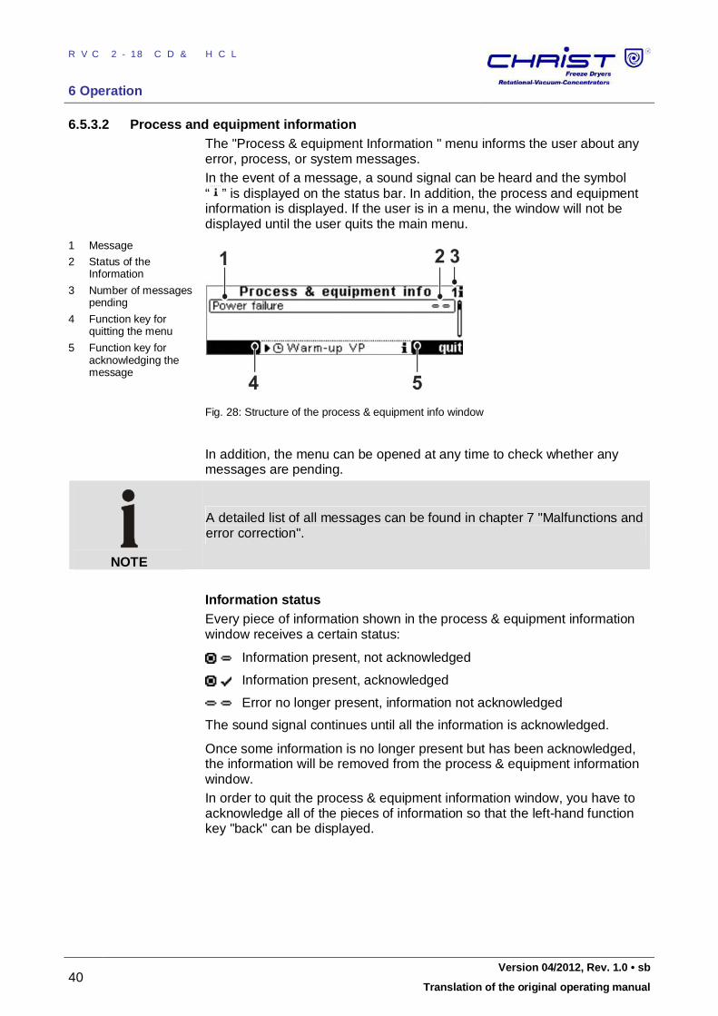
6.5.3.2 Process and equipment information The "Process & equipment Information " menu informs the user about any error, process, or system messages. In the event of a message, a sound signal can be heard and the symbol “ ” is displayed on the status bar. In addition, the process and equipment information is displayed. If the user is in a menu, the window will not be displayed until the user quits the main menu.
1 Message
2 Status of the Information
3 Number of messages pending
4 Function key for quitting the menu
5 Function key for acknowledging the message
Fig. 28: Structure of the process & equipment info window
In addition, the menu can be opened at any time to check whether any messages are pending.
NOTE
A detailed list of all messages can be found in chapter 7 "Malfunctions and error correction".
Information status Every piece of information shown in the process & equipment information window receives a certain status:
Information present, not acknowledged
Information present, acknowledged
Error no longer present, information not acknowledged
The sound signal continues until all the information is acknowledged.
Once some information is no longer present but has been acknowledged, the information will be removed from the process & equipment information window. In order to quit the process & equipment information window, you have to acknowledge all of the pieces of information so that the left-hand function key "back" can be displayed.
Pos: 132 /01 0 Univ ersal mod ule/ Sei tenwe chsel @ 0\ mod _12 021 1624 431 2_0 .docx @ 1 05 @ @ 1
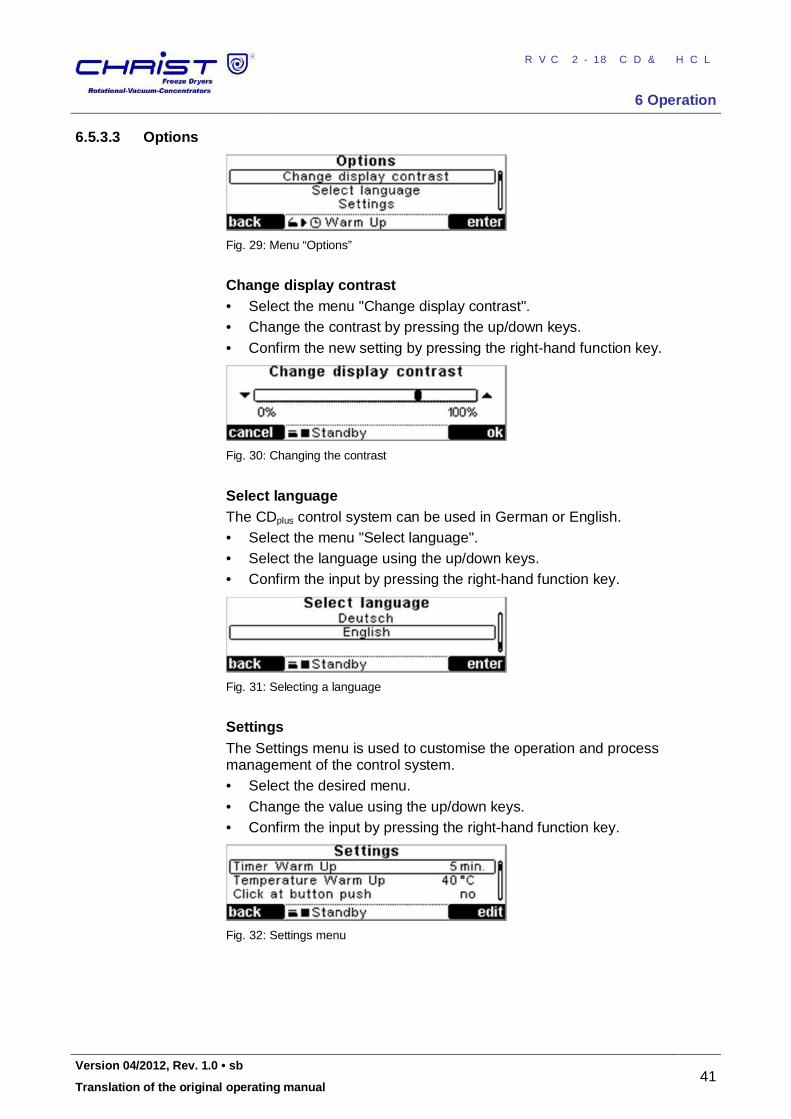
RVC 2-18 CD&HCL
6 Operation
Version 04/2012, Rev. 1.0 • sb 41
Translation of the original operating manual
Pos: 133 /20 0 Ch rist/3 61 RVC-BA (PROJEK TE)/RVC 2- 18 CD plus_ 2-1 8 CDplus _HCl/06 0 Bet rieb/ 060 -00 50- 003 0-0 050 Opti one n RVC 2- 18 CD plus @ 9\m od_ 132 090 6713 465 _68 .docx @ 5 4133 @ 4 @ 1
6.5.3.3 Options
Fig. 29: Menu “Options”
Change display contrast • Select the menu "Change display contrast". • Change the contrast by pressing the up/down keys. • Confirm the new setting by pressing the right-hand function key.
Fig. 30: Changing the contrast
Select language The CDplus control system can be used in German or English. • Select the menu "Select language". • Select the language using the up/down keys. • Confirm the input by pressing the right-hand function key.
Fig. 31: Selecting a language
Settings The Settings menu is used to customise the operation and process management of the control system. • Select the desired menu. • Change the value using the up/down keys. • Confirm the input by pressing the right-hand function key.
Fig. 32: Settings menu
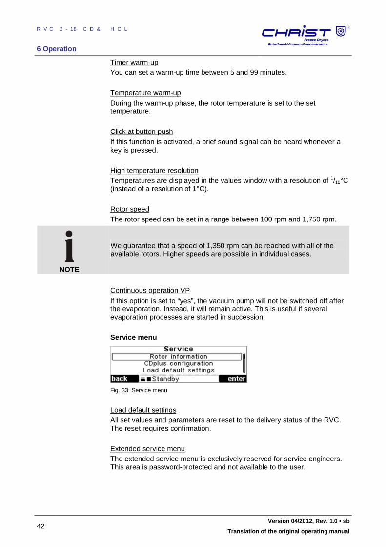
RVC 2-18 CD&HCL
6 Operation
42 Version 04/2012, Rev. 1.0 • sb
Translation of the original operating manual
Timer warm-up You can set a warm-up time between 5 and 99 minutes. Temperature warm-up During the warm-up phase, the rotor temperature is set to the set temperature. Click at button push If this function is activated, a brief sound signal can be heard whenever a key is pressed. High temperature resolution Temperatures are displayed in the values window with a resolution of 1/10°C (instead of a resolution of 1°C). Rotor speed The rotor speed can be set in a range between 100 rpm and 1,750 rpm.
NOTE
We guarantee that a speed of 1,350 rpm can be reached with all of the available rotors. Higher speeds are possible in individual cases.
Continuous operation VP If this option is set to “yes”, the vacuum pump will not be switched off after the evaporation. Instead, it will remain active. This is useful if several evaporation processes are started in succession. Service menu
Fig. 33: Service menu
Load default settings All set values and parameters are reset to the delivery status of the RVC. The reset requires confirmation. Extended service menu The extended service menu is exclusively reserved for service engineers. This area is password-protected and not available to the user.
Pos: 134 /01 0 Univ ersal mod ule/ Lee rzeile @ 0\ mo d_12 021 162 445 00_ 0.doc x @ 1 14 @ @ 1
Pos: 135 /20 0 Ch rist/3 60 RVC-BA (S TANDARDMODULE) /06 0 Betri eb/0 60- 006 0 Aussc halt en+ ++ +++ ++ ++ +++ ++ ++ +++ ++ ++ ++ + @ 8 \mo d_1 309 4265 648 76_ 68.d ocx @ 467 76 @ 2 @ 1
RVC 2-18 CD&HCL
6 Operation
Version 04/2012, Rev. 1.0 • sb 43
Translation of the original operating manual
6.6 Switching the RVC off The RVC must be in the standby status. • Switch the RVC off by pressing the mains power switch on the right-
hand side panel. Pos: 136 /01 0 Univ ersal mod ule/ Ab schnitt swechs el @ 0 \mo d_1 202 124 514 062_ 0.d ocx @ 418 @ @ 1
Pos: 137 /01 0 Univ ersal mod ule/ Sei tenwe chsel @ 0\ mod _12 021 1624 431 2_0 .docx @ 1 05 @ @ 1
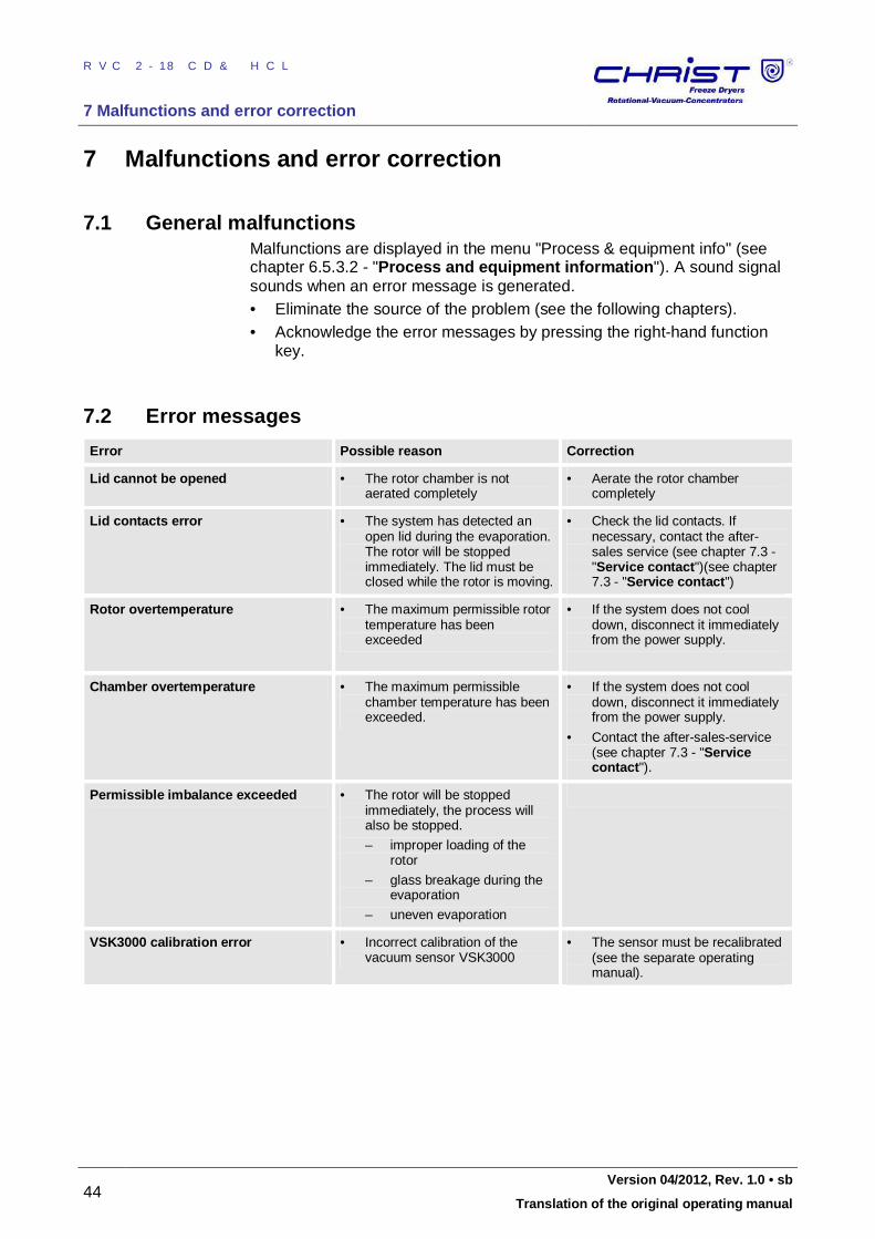
RVC 2-18 CD&HCL
7 Malfunctions and error correction
44 Version 04/2012, Rev. 1.0 • sb
Translation of the original operating manual
Pos: 138 /20 0 Ch rist/3 60 RVC-BA (S TANDARDMODULE) /07 0 Stör ung en u nd Fehl ersuc he/ 070 Stör ung en u nd Fehl ersuc he === == == === == == === == == === == = @ 8\m od_ 1309 939 131 742 _68. docx @ 47 129 @ 1 @ 1
7 Malfunctions and error correction
Pos: 139 /20 0 Ch rist/3 60 RVC-BA (S TANDARDMODULE) /07 0 Stör ung en u nd Fehl ersuc he/ 070 -00 10 Allg emei ne Stö run gen @ 8\ mod _13 099 413 440 43_ 68.d ocx @ 472 24 @ 2 @ 1
7.1 General malfunctions Malfunctions are displayed in the menu "Process & equipment info" (see chapter 6.5.3.2 - "Process and equipment information"). A sound signal sounds when an error message is generated. • Eliminate the source of the problem (see the following chapters). • Acknowledge the error messages by pressing the right-hand function
key. Pos: 140 /01 0 Univ ersal mod ule/ Lee rzeile @ 0\ mo d_12 021 162 445 00_ 0.doc x @ 1 14 @ @ 1
Pos: 141 /20 0 Ch rist/3 61 RVC-BA (PROJEK TE)/RVC 2- 18 CD plus_ 2-1 8 CDplus _HCl/07 0 Stö run gen und Fe hlers uche /070 -00 10 -001 0 Fehl er meldu nge n RVC 2- 18_ 2-1 8 HCl @ 12\ mod _13 359 3986 448 7_6 8.do cx @ 6414 1 @ 33 @ 1
7.2 Error messages
Error Possible reason Correction
Lid cannot be opened • The rotor chamber is not aerated completely
• Aerate the rotor chamber completely
Lid contacts error • The system has detected an open lid during the evaporation. The rotor will be stopped immediately. The lid must be closed while the rotor is moving.
• Check the lid contacts. If necessary, contact the after-sales service (see chapter 7.3 - "Service contact")(see chapter 7.3 - "Service contact")
Rotor overtemperature • The maximum permissible rotor temperature has been exceeded
• If the system does not cool down, disconnect it immediately from the power supply.
Chamber overtemperature • The maximum permissible chamber temperature has been exceeded.
• If the system does not cool down, disconnect it immediately from the power supply.
• Contact the after-sales-service (see chapter 7.3 - "Service contact").
Permissible imbalance exceeded • The rotor will be stopped immediately, the process will also be stopped.
– improper loading of the rotor
– glass breakage during the evaporation
– uneven evaporation
VSK3000 calibration error • Incorrect calibration of the vacuum sensor VSK3000
• The sensor must be recalibrated (see the separate operating manual).
Pos: 142 /01 0 Univ ersal mod ule/ Sei tenwe chsel @ 0\ mod _12 021 1624 431 2_0 .docx @ 1 05 @ 3 @ 1
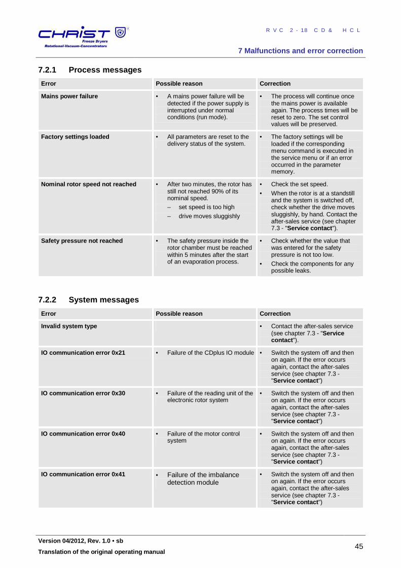
RVC 2-18 CD&HCL
7 Malfunctions and error correction
Version 04/2012, Rev. 1.0 • sb 45
Translation of the original operating manual
Pos: 143 /20 0 Ch rist/3 61 RVC-BA (PROJEK TE)/RVC 2- 18 CD plus_ 2-1 8 CDplus _HCl/07 0 Stö run gen und Fe hlers uche /070 -00 10 -002 0 Pr ozess meld ung en RVC 2 -18 _2- 18 HCl @ 12\ mo d_1 3359 398 649 60_ 68.d ocx @ 641 49 @ 33 @ 1
7.2.1 Process messages
Error Possible reason Correction
Mains power failure • A mains power failure will be detected if the power supply is interrupted under normal conditions (run mode).
• The process will continue once the mains power is available again. The process times will be reset to zero. The set control values will be preserved.
Factory settings loaded • All parameters are reset to the delivery status of the system.
• The factory settings will be loaded if the corresponding menu command is executed in the service menu or if an error occurred in the parameter memory.
Nominal rotor speed not reached • After two minutes, the rotor has still not reached 90% of its nominal speed.
– set speed is too high
– drive moves sluggishly
• Check the set speed.
• When the rotor is at a standstill and the system is switched off, check whether the drive moves sluggishly, by hand. Contact the after-sales service (see chapter 7.3 - "Service contact").
Safety pressure not reached • The safety pressure inside the rotor chamber must be reached within 5 minutes after the start of an evaporation process.
• Check whether the value that was entered for the safety pressure is not too low.
• Check the components for any possible leaks.
Pos: 144 /01 0 Univ ersal mod ule/ Lee rzeile @ 0\ mo d_12 021 162 445 00_ 0.doc x @ 1 14 @ 3 @ 1
Pos: 145 /20 0 Ch rist/3 60 RVC-BA (S TANDARDMODULE) /07 0 Stör ung en u nd Fehl ersuc he/ 070 -00 10- 003 0 Syste mm eldu ngen @ 8 \mo d_1 309 9391 353 52_ 68.d ocx @ 472 01 @ 3 @ 1
7.2.2 System messages
Error Possible reason Correction
Invalid system type • Contact the after-sales service (see chapter 7.3 - "Service contact").
IO communication error 0x21 • Failure of the CDplus IO module • Switch the system off and then on again. If the error occurs again, contact the after-sales service (see chapter 7.3 - "Service contact")
IO communication error 0x30 • Failure of the reading unit of the electronic rotor system
• Switch the system off and then on again. If the error occurs again, contact the after-sales service (see chapter 7.3 - "Service contact")
IO communication error 0x40 • Failure of the motor control system
• Switch the system off and then on again. If the error occurs again, contact the after-sales service (see chapter 7.3 - "Service contact")
IO communication error 0x41 • Failure of the imbalance detection module
• Switch the system off and then on again. If the error occurs again, contact the after-sales service (see chapter 7.3 - "Service contact")
Pos: 146 /01 0 Univ ersal mod ule/ Lee rzeile @ 0\ mo d_12 021 162 445 00_ 0.doc x @ 1 14 @ 3 @ 1
Pos: 147 /20 0 Ch rist/3 61 RVC-BA (PROJEK TE)/RVC 2- 18 CD plus_ 2-1 8 CDplus _HCl/07 0 Stö run gen und Fe hlers uche /070 -00 10 -004 0 N oten trieg elun g @ 9\mo d_1 320 657 377 043 _68. docx @ 54 003 @ 3 @ 1
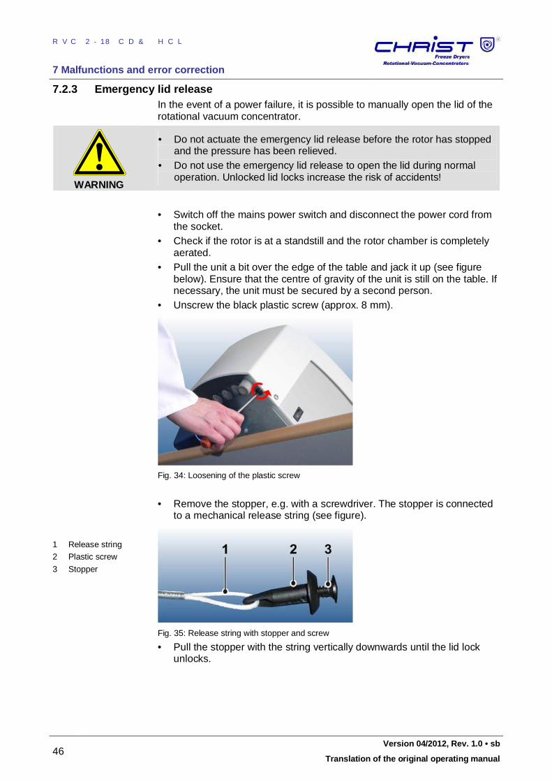
RVC 2-18 CD&HCL
7 Malfunctions and error correction
46 Version 04/2012, Rev. 1.0 • sb
Translation of the original operating manual
7.2.3 Emergency lid release In the event of a power failure, it is possible to manually open the lid of the rotational vacuum concentrator.
WARNING
• Do not actuate the emergency lid release before the rotor has stopped and the pressure has been relieved.
• Do not use the emergency lid release to open the lid during normal operation. Unlocked lid locks increase the risk of accidents!
• Switch off the mains power switch and disconnect the power cord from
the socket. • Check if the rotor is at a standstill and the rotor chamber is completely
aerated. • Pull the unit a bit over the edge of the table and jack it up (see figure
below). Ensure that the centre of gravity of the unit is still on the table. If necessary, the unit must be secured by a second person.
• Unscrew the black plastic screw (approx. 8 mm).
Fig. 34: Loosening of the plastic screw
• Remove the stopper, e.g. with a screwdriver. The stopper is connected
to a mechanical release string (see figure).
1 Release string
2 Plastic screw
3 Stopper
Fig. 35: Release string with stopper and screw
• Pull the stopper with the string vertically downwards until the lid lock unlocks.
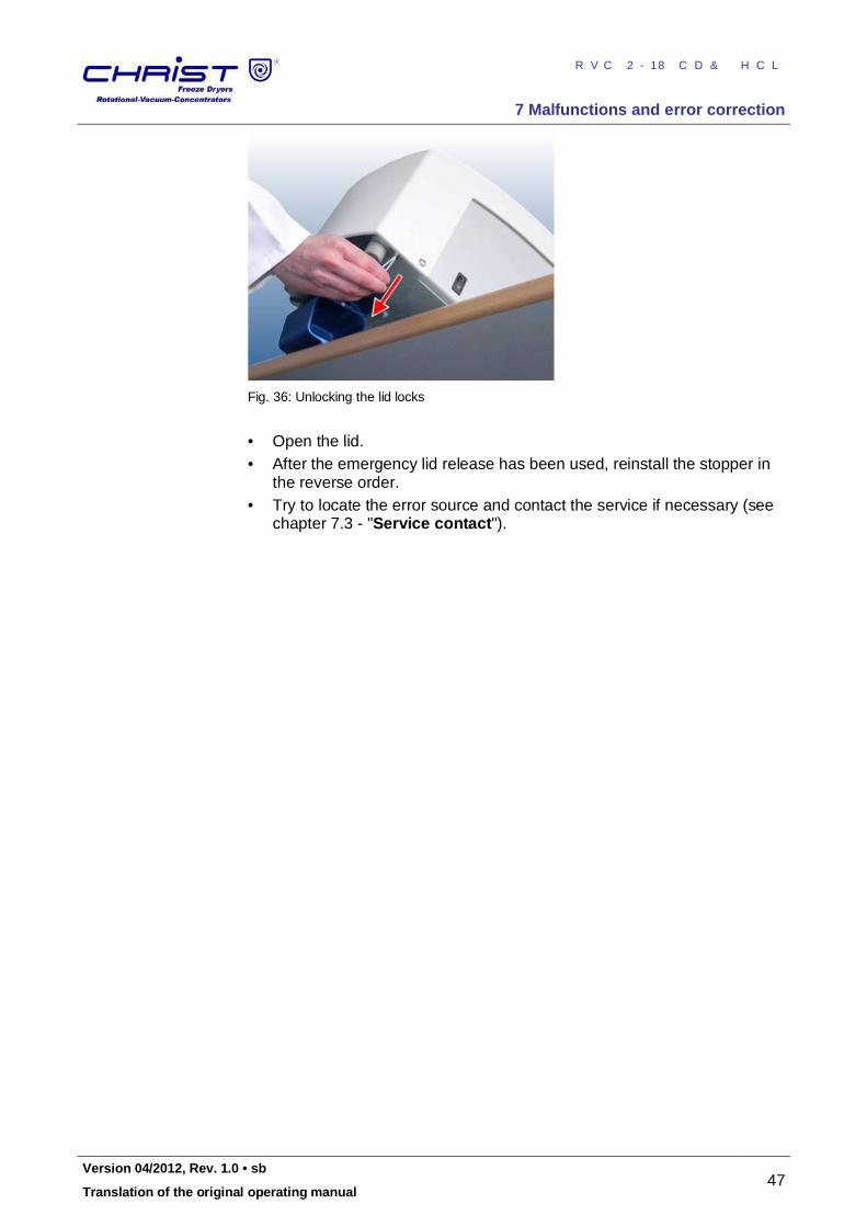
RVC 2-18 CD&HCL
7 Malfunctions and error correction
Version 04/2012, Rev. 1.0 • sb 47
Translation of the original operating manual
Fig. 36: Unlocking the lid locks
• Open the lid. • After the emergency lid release has been used, reinstall the stopper in
the reverse order. • Try to locate the error source and contact the service if necessary (see
chapter 7.3 - "Service contact"). Pos: 148 /01 0 Univ ersal mod ule/ Sei tenwe chsel @ 0\ mod _12 021 1624 431 2_0 .docx @ 1 05 @ 3 @ 1

RVC 2-18 CD&HCL
7 Malfunctions and error correction
48 Version 04/2012, Rev. 1.0 • sb
Translation of the original operating manual
Pos: 149 /20 0 Ch rist/3 60 RVC-BA (S TANDARDMODULE) /07 0 Stör ung en u nd Fehl ersuc he/ 070 -00 10- 005 0 Kleinfl ansch ver bindu nge n @ 12\ mod_ 133 517 283 489 6_6 8.docx @ 6 288 9 @ 3 @ 1
7.2.4 Small flange connections Leakages are often due to improper small flange connections between the various components and hose connections or to leakages in the valves. • Loosen the connection and place the centring ring (with sealing ring
inside) in a centred manner between the flange connections. • Seal the connection with the clamping ring or clamping chain by
tightening the wing nut. • Ensure that the centring ring neither slips out of place nor gets jammed.
Fig. 37: Small flange and centring ring Fig. 38: Small flange with centring ring
and small flange
Fig. 39: Attaching the clamping ring Fig. 40: Tightened clamping ring Pos: 150 /01 0 Univ ersal mod ule/ Sei tenwe chsel @ 0\ mod _12 021 1624 431 2_0 .docx @ 1 05 @ 2 @ 1
RVC 2-18 CD&HCL
7 Malfunctions and error correction
Version 04/2012, Rev. 1.0 • sb 49
Translation of the original operating manual
Pos: 151 /20 0 Ch rist/3 60 RVC-BA (S TANDARDMODULE) /07 0 Stör ung en u nd Fehl ersuc he/ 070 -00 20 Ko ntakt im Se rvicef all @ 8\ mo d_13 099 391 357 11_ 68.d ocx @ 472 09 @ 2 @ 1
7.3 Service contact In the event of queries, malfunctions, or spare part enquiries: From Germany: • Use the service request form at
www.martinchrist.de [Service Area] or contact • Martin Christ Gefriertrocknungsanlagen GmbH
An der Unteren Söse 50 37520 Osterode (Germany) Tel. +49 (0) 55 22 / 50 07-8425 Fax +49 (0) 55 22 / 50 07-9425 E-mail: [email protected]
Outside Germany: • Contact our agency in your country. All agencies are listed at
www.martinchrist.de [Contacts] [Foreign agencies]
NOTE
• If you would like to utilise our after-sales-service, please state the type of your RVC and its serial number.
• Please use our service request on the Internet (see above).
Pos: 152 /01 0 Univ ersal mod ule/ Ab schnitt swechs el @ 0 \mo d_1 202 124 514 062_ 0.d ocx @ 418 @ @ 1
Pos: 153 /01 0 Univ ersal mod ule/ Sei tenwe chsel @ 0\ mod _12 021 1624 431 2_0 .docx @ 1 05 @ 1 @ 1
RVC 2-18 CD&HCL
8 Maintenance and service
50 Version 04/2012, Rev. 1.0 • sb
Translation of the original operating manual
Pos: 154 /20 0 Ch rist/3 60 RVC-BA (S TANDARDMODULE) /08 0 Wart ung un d Inst and haltu ng/ 080 Wart ung und Inst and haltu ng= == == === == == === == == === == == = @ 8\mo d_1 309 944 760 465 _68. docx @ 47 238 @ 1 @ 1
8 Maintenance and service The rotational vacuum concentrator and the accessories are subject to high mechanical stress. Thorough maintenance performed by the user extends the service life and prevents premature failure.
CAUTION
If corrosion or other damage occurs due to improper care, the manufacturer cannot be held liable or subject to any warranty claims.
• Use soap water or other water-soluble, mild cleaning agents for cleaning the RVC and the accessories.
• Do not use any corrosive or aggressive substances. • Do not use solvents. • Do not use agents with abrasive particles. • Do not expose the RVC or its accessories to intensive UV radiation (e.g.
sunlight) or thermal stress (e.g. by heat generators). Pos: 155 /01 0 Univ ersal mod ule/ Lee rzeile @ 0\ mo d_12 021 162 445 00_ 0.doc x @ 1 14 @ 2 @ 1
Pos: 156 /20 0 Ch rist/3 60 RVC-BA (S TANDARDMODULE) /08 0 Wart ung un d Inst and haltu ng/ 080 -001 0 W artu ngsa rbei ten --- --- -- --- -- --- -- --- --- -- --- -- --- --- -- --- -- --- -- --- --- -- --- -- --- --- -- --- @ 8\ mo d_13 099 447 608 24_ 68.d ocx @ 472 46 @ 33 @ 1
8.1 Maintenance
Pos: 157 /20 0 Ch rist/3 60 RVC-BA (S TANDARDMODULE) /08 0 Wart ung un d Inst and haltu ng/ 080 -001 0- 0010 Rot ation s-Vaku um -Konze ntr ator @ 8\ mo d_1 3099 449 488 64_ 68.d ocx @ 472 54 @ 3 @ 1
8.1.1 Rotational vacuum concentrator • Switch off the rotational vacuum concentrator via the mains power
switch and disconnect the power cord before cleaning. • Carefully remove all product residues from the rotor chamber using a
cloth. • If the rotational vacuum concentrator has been contaminated with toxic,
radioactive, or pathogenic substances, clean the rotor chamber immediately with a suitable decontamination agent (depending on the type of contamination).
WARNING
Take suitable precautions for your own safety if there is a risk of toxic, radioactive, or pathogenic contamination.
• Check the safety guard of the fan (at the front of the bottom side) at
least once a year for dirt and clean it if necessary (e.g. with a vacuum cleaner).
• Open the rotational vacuum concentrator when it is not in use so that moisture can evaporate.
Pos: 158 /01 0 Univ ersal mod ule/ Sei tenwe chsel @ 0\ mod _12 021 1624 431 2_0 .docx @ 1 05 @ 3 @ 1
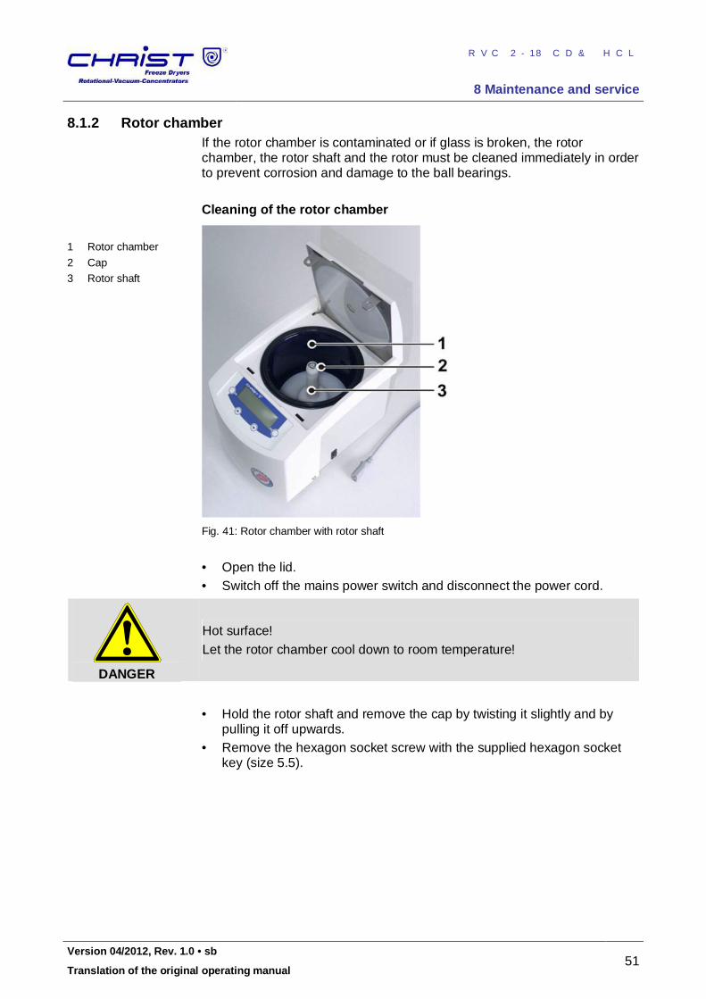
RVC 2-18 CD&HCL
8 Maintenance and service
Version 04/2012, Rev. 1.0 • sb 51
Translation of the original operating manual
Pos: 159 /20 0 Ch rist/3 61 RVC-BA (PROJEK TE)/RVC 2- 18 CD plus_ 2-1 8 CDplus _HCl/08 0 Wa rtun g un d In stan dhalt ung/ 080 -00 10- 002 1 Ro tork am mer HCl @ 1 2\m od_ 133 5341 579 279 _68. docx @ 64 031 @ 3 @ 1
8.1.2 Rotor chamber If the rotor chamber is contaminated or if glass is broken, the rotor chamber, the rotor shaft and the rotor must be cleaned immediately in order to prevent corrosion and damage to the ball bearings. Cleaning of the rotor chamber
1 Rotor chamber
2 Cap
3 Rotor shaft
Fig. 41: Rotor chamber with rotor shaft
• Open the lid. • Switch off the mains power switch and disconnect the power cord.
DANGER
Hot surface! Let the rotor chamber cool down to room temperature!
• Hold the rotor shaft and remove the cap by twisting it slightly and by
pulling it off upwards. • Remove the hexagon socket screw with the supplied hexagon socket
key (size 5.5).
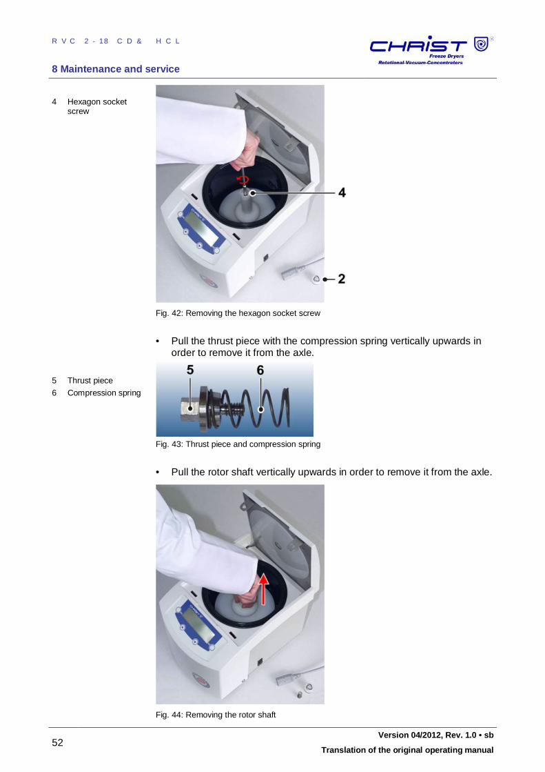
RVC 2-18 CD&HCL
8 Maintenance and service
52 Version 04/2012, Rev. 1.0 • sb
Translation of the original operating manual
4 Hexagon socket screw
Fig. 42: Removing the hexagon socket screw
• Pull the thrust piece with the compression spring vertically upwards in
order to remove it from the axle.
5 Thrust piece
6 Compression spring
Fig. 43: Thrust piece and compression spring
• Pull the rotor shaft vertically upwards in order to remove it from the axle.
Fig. 44: Removing the rotor shaft
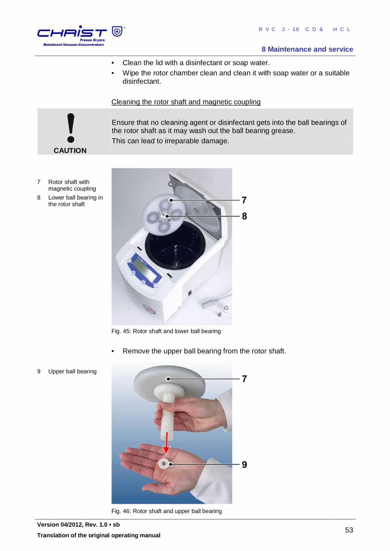
RVC 2-18 CD&HCL
8 Maintenance and service
Version 04/2012, Rev. 1.0 • sb 53
Translation of the original operating manual
• Clean the lid with a disinfectant or soap water. • Wipe the rotor chamber clean and clean it with soap water or a suitable
disinfectant. Cleaning the rotor shaft and magnetic coupling
CAUTION
Ensure that no cleaning agent or disinfectant gets into the ball bearings of the rotor shaft as it may wash out the ball bearing grease. This can lead to irreparable damage.
7 Rotor shaft with magnetic coupling
8 Lower ball bearing in the rotor shaft
Fig. 45: Rotor shaft and lower ball bearing
• Remove the upper ball bearing from the rotor shaft.
9 Upper ball bearing
Fig. 46: Rotor shaft and upper ball bearing
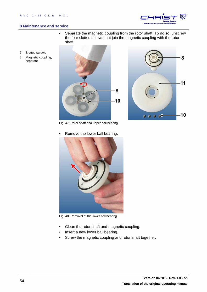
RVC 2-18 CD&HCL
8 Maintenance and service
54 Version 04/2012, Rev. 1.0 • sb
Translation of the original operating manual
• Separate the magnetic coupling from the rotor shaft. To do so, unscrew the four slotted screws that join the magnetic coupling with the rotor shaft.
7 Slotted screws
8 Magnetic coupling, separate
Fig. 47: Rotor shaft and upper ball bearing
• Remove the lower ball bearing.
Fig. 48: Removal of the lower ball bearing
• Clean the rotor shaft and magnetic coupling. • Insert a new lower ball bearing. • Screw the magnetic coupling and rotor shaft together.
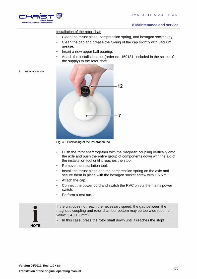
RVC 2-18 CD&HCL
8 Maintenance and service
Version 04/2012, Rev. 1.0 • sb 55
Translation of the original operating manual
Installation of the rotor shaft • Clean the thrust piece, compression spring, and hexagon socket key. • Clean the cap and grease the O-ring of the cap slightly with vacuum
grease. • Insert a new upper ball bearing. • Attach the installation tool (order no. 169181, included in the scope of
the supply) to the rotor shaft.
9 Installation tool
Fig. 49: Positioning of the installation tool
• Push the rotor shaft together with the magnetic coupling vertically onto
the axle and push the entire group of components down with the aid of the installation tool until it reaches the stop.
• Remove the installation tool. • Install the thrust piece and the compression spring on the axle and
secure them in place with the hexagon socket screw with 1.5 Nm. • Attach the cap. • Connect the power cord and switch the RVC on via the mains power
switch. • Perform a test run.
NOTE
If the unit does not reach the necessary speed, the gap between the magnetic coupling and rotor chamber bottom may be too wide (optimum value: 2.4 0.3mm). • In this case, press the rotor shaft down until it reaches the stop!
Pos: 160 /01 0 Univ ersal mod ule/ Sei tenwe chsel @ 0\ mod _12 021 1624 431 2_0 .docx @ 1 05 @ 3 @ 1
RVC 2-18 CD&HCL
8 Maintenance and service
56 Version 04/2012, Rev. 1.0 • sb
Translation of the original operating manual
Pos: 161 /20 0 Ch rist/3 60 RVC-BA (S TANDARDMODULE) /08 0 Wart ung un d Inst and haltu ng/ 080 -001 0- 0030 Zube hör @ 8\ mo d_1 3100 265 340 81_ 68.d ocx @ 472 71 @ 3 @ 1
8.1.3 Accessories
CAUTION
For the care of the accessories, special safety measures must be considered as these are measures that will ensure operational safety at the same time.
Chemical reactions as well as stress-corrosion (combination of oscillating pressure and chemical reaction) can affect or destroy the metals. Barely detectable cracks on the surface can expand and weaken the material without any visible signs. • Check the material regularly (at least once a month) for
– cracks – visible damage of the surface – pressure marks – signs of corrosion – other changes.
• Replace any damaged components immediately for your own safety. • Immediately rinse off the rotors or accessories if any liquids that may
cause corrosion come into contact with them. • Clean the accessories outside the rotational vacuum concentrator once
a week or preferably after each use. • If the rotors or accessories have been contaminated with toxic,
radioactive, or pathogenic substances, clean them immediately with a suitable decontamination agent (depending on the type of contamination). Take suitable precautions for your own safety if there is a risk of toxic, radioactive, or pathogenic contamination.
Pos: 162 /01 0 Univ ersal mod ule/ Lee rzeile @ 0\ mo d_12 021 162 445 00_ 0.doc x @ 1 14 @ 4 @ 1
Pos: 163 /20 0 Ch rist/3 60 RVC-BA (S TANDARDMODULE) /08 0 Wart ung un d Inst and haltu ng/ 080 -001 0- 0030 -00 10 Alumini umzu beh ör @ 8\ mod _131 002 678 982 9_6 8.doc x @ 4 727 8 @ 4 @ 1
8.1.3.1 Aluminium accessories Especially aluminium parts are susceptible to corrosion. • Acid-containing cleaning agents and alkaline cleaning agents must be
avoided. • Grease aluminium parts at least once a week with slushing oil for the
protection against corrosion. This essentially increases their service life and reduces susceptibility to corrosion.
Pos: 164 /01 0 Univ ersal mod ule/ Sei tenwe chsel @ 0\ mod _12 021 1624 431 2_0 .docx @ 1 05 @ 3 @ 1
RVC 2-18 CD&HCL
8 Maintenance and service
Version 04/2012, Rev. 1.0 • sb 57
Translation of the original operating manual
Pos: 165 /20 0 Ch rist/3 60 RVC-BA (S TANDARDMODULE) /08 0 Wart ung un d Inst and haltu ng/ 080 -001 0- 0040 Glas br uch @ 8\m od_ 131 002 690 5087 _68 .docx @ 4 728 5 @ 3 @ 1
8.1.4 Glass breakage
CAUTION
In the case of glass breakage, immediately remove all glass particles (e.g. with a vacuum cleaner). Replace the rubber cushions since even thorough cleaning will not remove all glass particles.
Glass particles will damage the surface coating (e.g. anodising) of the buckets, which will then lead to corrosion. Glass particles in the rubber cushions of the buckets will cause glass breakage again. Glass particles on the pivot bearing of the load- bearing bolts prevent the buckets and rotor blocks from swinging evenly, which will cause an imbalance. Glass particles in the rotor chamber will cause metal abrasion due to the circulation. This metal dust will not only pollute the rotor chamber, rotor, and materials to be evaporated but also damage the surfaces of the accessories, rotors, and rotor chamber. In order to completely remove the glass particles and metal dust from the rotor chamber • Grease the upper third of the rotor chamber with e.g. Vaseline. • Then, let the rotor rotate for a few minutes at maximum speed and
atmospheric pressure. The glass and metal particles will now collect at the greased part.
• Remove the grease with the glass and metal particles with a cloth. • If necessary, repeat this procedure. • Clean the rotor shaft.
Pos: 166 /01 0 Univ ersal mod ule/ Lee rzeile @ 0\ mo d_12 021 162 445 00_ 0.doc x @ 1 14 @ 2 @ 1
Pos: 167 /20 0 Ch rist/3 60 RVC-BA (S TANDARDMODULE) /08 0 Wart ung un d Inst and haltu ng/ 080 -002 0 D esinfek tion v on R otork am mer un d Zube hör @ 8\ mod _13 100 270 5588 9_6 8.d ocx @ 472 92 @ 2 @ 1
8.2 Disinfection of the rotor chamber and accessories • Use commercially-available disinfectants such as, for example, Incidur®,
Meliseptol®, Sagrotan®, Buraton® or Terralin® (available at chemist’s shops or drugstores).
• The rotational vacuum concentrator and the accessories consist of various materials. A possible incompatibility must be considered.
• Before using cleaning or decontamination agents that were not recommended by us, contact the manufacturer to ensure that such a procedure will not damage the rotational vacuum concentrator.
• For autoclaving, consider the continuous heat resistance of the individual materials.
• Please contact us if you have any queries (see chapter 8.4 - "Service").
DANGER
If dangerous materials (e.g. infectious and pathogenic substances) are used, the RVC and the accessories must be disinfected.
Pos: 168 /01 0 Univ ersal mod ule/ Lee rzeile @ 0\ mo d_12 021 162 445 00_ 0.doc x @ 1 14 @ 2 @ 1
Pos: 169 /20 0 Ch rist/3 60 RVC-BA (S TANDARDMODULE) /08 0 Wart ung un d Inst and haltu ng/ 080 -003 0 Au toklavie re n des Zu beh örs @ 8\ mod _13 1002 727 058 8_6 8.do cx @ 4 729 9 @ 2 @ 1
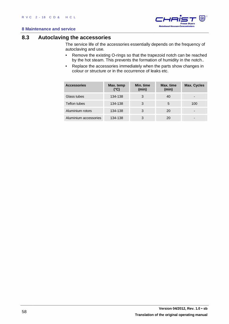
RVC 2-18 CD&HCL
8 Maintenance and service
58 Version 04/2012, Rev. 1.0 • sb
Translation of the original operating manual
8.3 Autoclaving the accessories The service life of the accessories essentially depends on the frequency of autoclaving and use. • Remove the existing O-rings so that the trapezoid notch can be reached
by the hot steam. This prevents the formation of humidity in the notch.. • Replace the accessories immediately when the parts show changes in
colour or structure or in the occurrence of leaks etc.
Accessories Max. temp (°C)
Min. time (min)
Max. time (min)
Max. Cycles
Glass tubes 134-138 3 40 -
Teflon tubes 134-138 3 5 100
Aluminium rotors 134-138 3 20 -
Aluminium accessories 134-138 3 20 - Pos: 170 /01 0 Univ ersal mod ule/ Sei tenwe chsel @ 0\ mod _12 021 1624 431 2_0 .docx @ 1 05 @ 2 @ 1
RVC 2-18 CD&HCL
8 Maintenance and service
Version 04/2012, Rev. 1.0 • sb 59
Translation of the original operating manual
Pos: 171 /20 0 Ch rist/3 60 RVC-BA (S TANDARDMODULE) /08 0 Wart ung un d Inst and haltu ng/ 080 -004 0 I nsta ndh altun gsar beite n @ 8\m od_1 310 027 462 633 _68. docx @ 47 306 @ 2 @ 1
8.4 Service
DANGER
In the event of service work that requires the removal of the panels, there is a risk of electric shock or mechanical injury. Only qualified specialist personnel is authorised to perform this service work..
The rotational vacuum concentrator is subject to high mechanical stress. In order to be able to withstand this high level of stress, high-quality components were used during the production of the rotational vacuum concentrators. Nevertheless, wear cannot be excluded and it may not be visible from the outside. This is why we recommend having the rotational vacuum concentrator checked by the manufacturer during an inspection once per year in the operating state and once every three years in the dismantled state. Information and appointments: In Germany: • Use the service request form at
www.martinchrist.de [Service area] or contact • Martin Christ Gefriertrocknungsanlagen GmbH
An der Unteren Söse 50 37520 Osterode Tel. +49 (0) 55 22 / 50 07-84 25 Fax +49 (0) 55 22 / 50 07-94 25 E-mail: [email protected]
Outside Germany: • Contact our agency in your country. All agencies are listed at
www.martinchrist.de [Contacts] [Foreign agencies]
NOTE
• If you would like to utilise our service, please state the type of your RVC and its serial number.
• Please use the online service request on the Internet.
Pos: 172 /01 0 Univ ersal mod ule/ Sei tenwe chsel @ 0\ mod _12 021 1624 431 2_0 .docx @ 1 05 @ 3 @ 1
RVC 2-18 CD&HCL
8 Maintenance and service
60 Version 04/2012, Rev. 1.0 • sb
Translation of the original operating manual
Pos: 173 /20 0 Ch rist/3 60 RVC-BA (S TANDARDMODULE) /08 0 Wart ung un d Inst and haltu ng/ 080 -005 0 R ücksen dun g d efekt er Teile @ 8\ mod _13 1002 805 897 6_6 8.do cx @ 4 732 0 @ 32 @ 1
8.5 Return of defective parts
Although we exercise great care during the production of our products, it may be necessary to return a unit or accessory to the manufacturer. In order to ensure the quick and economical processing of returns of freeze-dryers, rotational vacuum concentrators, spare parts, or accessories, we require complete and extensive information concerning the process. Please fill in the following forms completely, sign them, and enclose them with the return package: 1. Declaration of decontamination
As a certified company and due to the legal regulations for the protection of our employees and of the environment, we are obliged to certify the harmlessness of all incoming goods. For this purpose, we require a declaration of decontamination. • The form must be filled in completely and signed by authorised and
specialised personnel only. • Affix the original form in a clearly visible manner to the outside of the
packaging.
NOTE
If no such declaration is enclosed in the return package, we will perform the decontamination at your expense!
2. Form for the return of defective parts
This form is for the product-related data. They facilitate the assignment, and they enable the quick processing of the return. If several parts are returned together in one packaging, please enclose a separate problem description for every defective part. • A detailed problem description is necessary in order to perform the
repair quickly and economically. • Please note on the form if you would like to receive a cost estimate.
Cost estimates are only prepared upon request and against charge. If an order is placed, these charges will be offset.
NOTE
The unit must be packaged in a transport-safe manner. Please use the original packaging, if at all possible. If the product is dispatched to us in unsuitable packaging, you will be charged the cost for returning it to you in new packaging.
The forms can be downloaded online from www.martinchrist.de [Service Area].
Pos: 174 /01 0 Univ ersal mod ule/ Ab schnitt swechs el @ 0 \mo d_1 202 124 514 062_ 0.d ocx @ 418 @ 2 @ 1
Pos: 175 /01 0 Univ ersal mod ule/ Sei tenwe chsel @ 0\ mod _12 021 1624 431 2_0 .docx @ 1 05 @ 2 @ 1
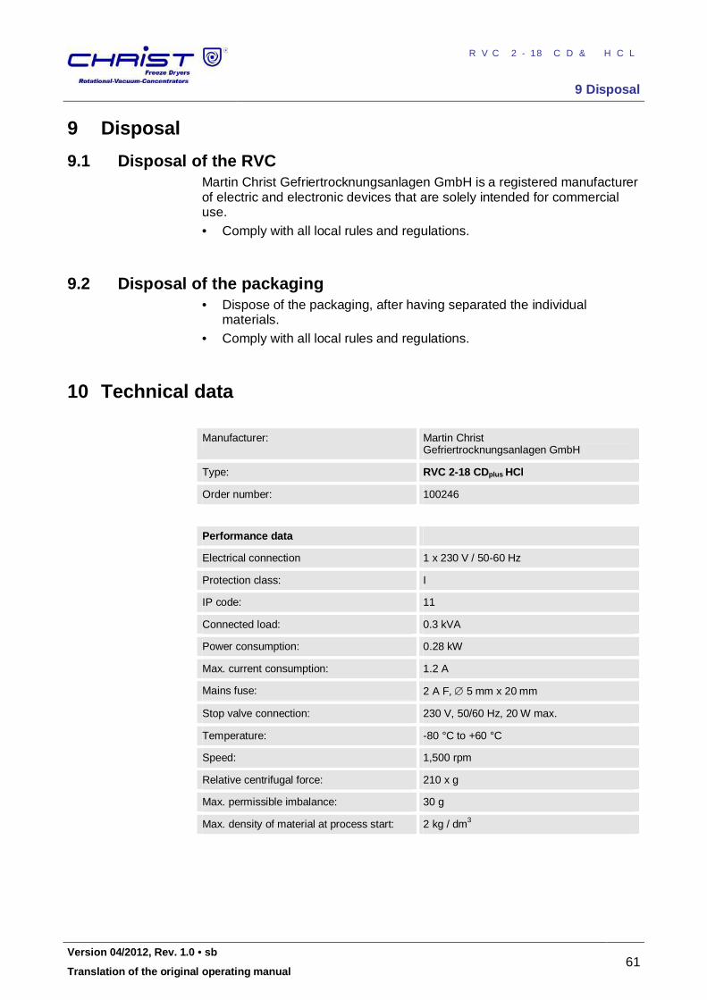
RVC 2-18 CD&HCL
9 Disposal
Version 04/2012, Rev. 1.0 • sb 61
Translation of the original operating manual
Pos: 176 /20 0 Ch rist/3 60 RVC-BA (S TANDARDMODULE) /09 0 Entso rgu ng/0 90 Entso rgu ng= == === == == == === == == === == == === == == === == == == @ 8\ mod _131 002 812 705 5_6 8.doc x @ 4 732 8 @ 22 @ 1
9 Disposal Pos: 177 /20 0 Ch rist/3 60 RVC-BA (S TANDARDMODULE) /09 0 Entso rgu ng/0 90- 001 0 Ent sor gun g des Rota tions -Vakuu m-Ko nzen trat ors @ 8\ mod _13 100 2812 738 3_6 8.do cx @ 4 733 6 @ 21 @ 1
9.1 Disposal of the RVC Martin Christ Gefriertrocknungsanlagen GmbH is a registered manufacturer of electric and electronic devices that are solely intended for commercial use. • Comply with all local rules and regulations.
Pos: 178 /01 0 Univ ersal mod ule/ Lee rzeile @ 0\ mo d_12 021 162 445 00_ 0.doc x @ 1 14 @ 22 @ 1
Pos: 179 /20 0 Ch rist/3 60 RVC-BA (S TANDARDMODULE) /09 0 Entso rgu ng/0 90- 002 0 Ent sor gun g de r Ver packu ng @ 8\ mod _13 1002 812 774 2_6 8.doc x @ 4 734 4 @ 22 @ 1
9.2 Disposal of the packaging • Dispose of the packaging, after having separated the individual
materials. • Comply with all local rules and regulations.
Pos: 180 /01 0 Univ ersal mod ule/ Ab schnitt swechs el @ 0 \mo d_1 202 124 514 062_ 0.d ocx @ 418 @ 2 @ 1
Pos: 181 /20 0 Ch rist/3 61 RVC-BA (PROJEK TE)/RVC 2- 18 CD plus_ 2-1 8 CDplus _HCl/10 0 Tech nische D ate n/10 1 Tech nische Date n HCl @ 12\ mod _133 542 527 785 0_6 8.doc x @ 6 405 0 @ 21 @ 1
10 Technical data
Manufacturer: Martin Christ Gefriertrocknungsanlagen GmbH
Type: RVC 2-18 CDplus HCl
Order number: 100246
Performance data
Electrical connection 1 x 230 V / 50-60 Hz
Protection class: I
IP code: 11
Connected load: 0.3 kVA
Power consumption: 0.28 kW
Max. current consumption: 1.2 A
Mains fuse: 2 A F, 5 mm x 20 mm
Stop valve connection: 230 V, 50/60 Hz, 20 W max.
Temperature: -80 °C to +60 °C
Speed: 1,500 rpm
Relative centrifugal force: 210 x g
Max. permissible imbalance: 30 g
Max. density of material at process start: 2 kg / dm3
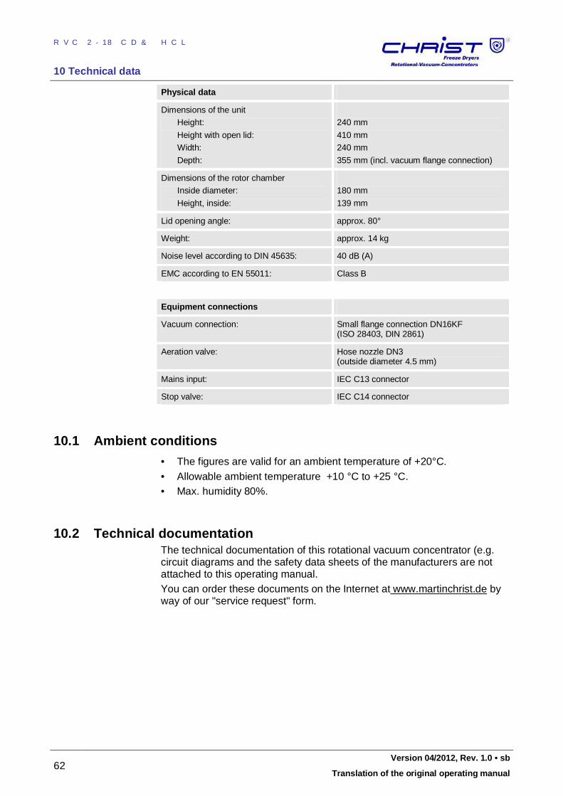
RVC 2-18 CD&HCL
10 Technical data
62 Version 04/2012, Rev. 1.0 • sb
Translation of the original operating manual
Physical data
Dimensions of the unit
Height:
Height with open lid:
Width:
Depth:
240 mm
410 mm
240 mm
355 mm (incl. vacuum flange connection)
Dimensions of the rotor chamber
Inside diameter:
Height, inside:
180 mm
139 mm
Lid opening angle: approx. 80°
Weight: approx. 14 kg
Noise level according to DIN 45635: 40 dB (A)
EMC according to EN 55011: Class B
Equipment connections
Vacuum connection: Small flange connection DN16KF (ISO 28403, DIN 2861)
Aeration valve: Hose nozzle DN3 (outside diameter 4.5 mm)
Mains input: IEC C13 connector
Stop valve: IEC C14 connector Pos: 182 /01 0 Univ ersal mod ule/ Lee rzeile @ 0\ mo d_12 021 162 445 00_ 0.doc x @ 1 14 @ 1 @ 1
Pos: 183 /20 0 Ch rist/3 60 RVC-BA (S TANDARDMODULE) /10 0 Technisc he Da ten/ 100 -00 10 Umg ebu ngsb eding ung en- -- --- -- --- --- -- --- -- --- -- --- --- -- --- -- --- --- - @ 8\m od_ 131 002 9990 683 _68 .docx @ 4 7359 @ 1 2 @ 1
10.1 Umgeb ungs bedi ngu nge n
10.1 Ambient conditions Pos: 184 /20 0 Ch rist/3 60 RVC-BA (S TANDARDMODULE) /10 0 Technisc he Da ten/ 100 -00 10 Umg ebu ngsb eding ung en Text @ 8\ mod _13 100 299 910 27_ 68.d ocx @ 473 67 @ 2 @ 1
10.1 Umgeb ungs bedi ngu nge n
• The figures are valid for an ambient temperature of +20°C. • Allowable ambient temperature +10 °C to +25 °C. • Max. humidity 80%.
Pos: 185 /01 0 Univ ersal mod ule/ Lee rzeile @ 0\ mo d_12 021 162 445 00_ 0.doc x @ 1 14 @ 2 @ 1
Pos: 186 /20 0 Ch rist/3 60 RVC-BA (S TANDARDMODULE) /10 0 Technisc he Da ten/ 100 -00 20 Tec hnisch e Dok ume ntati on @ 8\m od_ 131 002 999 140 2_68 .docx @ 4 737 5 @ 2 @ 1
10.2 Technical documentation The technical documentation of this rotational vacuum concentrator (e.g. circuit diagrams and the safety data sheets of the manufacturers are not attached to this operating manual. You can order these documents on the Internet at www.martinchrist.de by way of our "service request" form.
Pos: 187 /01 0 Univ ersal mod ule/ Ab schnitt swechs el @ 0 \mo d_1 202 124 514 062_ 0.d ocx @ 418 @ 2 @ 1
Pos: 188 /01 0 Univ ersal mod ule/ Sei tenwe chsel @ 0\ mod _12 021 1624 431 2_0 .docx @ 1 05 @ 2 @ 1
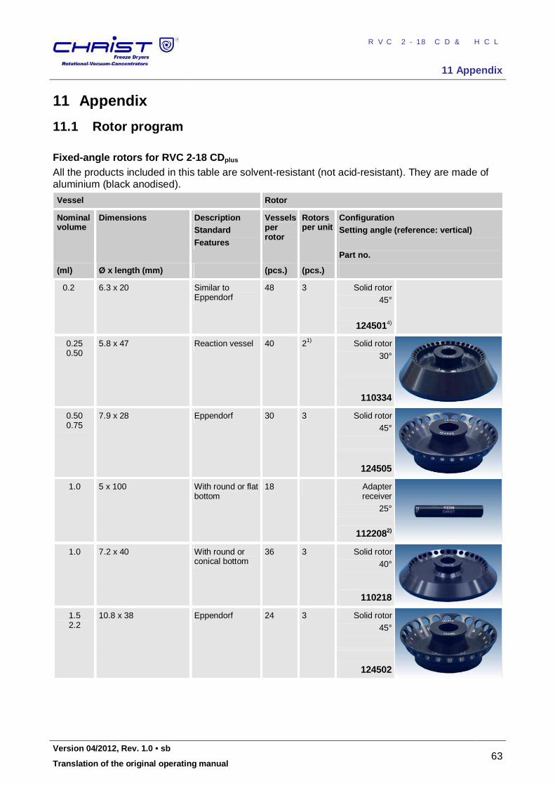
RVC 2-18 CD&HCL
11 Appendix
Version 04/2012, Rev. 1.0 • sb 63
Translation of the original operating manual
Pos: 189 /20 0 Ch rist/3 60 RVC-BA (S TANDARDMODULE) /11 0 Anha ng/ 110 A nha ng= == === == == === == == === == == == === == == === == == === == == == @ 8\ mod_ 131 003 037 974 6_6 8.doc x @ 4 739 1 @ 22 @ 1
11 Appendix Pos: 190 /20 0 Ch rist/3 61 RVC-BA (PROJEK TE)/RVC 2- 18 CD plus_ 2-1 8 CDplus _HCl/11 0 Anh ang/ 110 -00 20 Roto rpr ogr am m @ 9\m od_1 320 657 412 297 _68. docx @ 54 027 @ 21 @ 1
11.1 Rotor program Fixed-angle rotors for RVC 2-18 CDplus All the products included in this table are solvent-resistant (not acid-resistant). They are made of aluminium (black anodised).
Vessel Rotor
Nominal volume
Dimensions Description Standard Features
Vessels per rotor
Rotors per unit
Configuration Setting angle (reference: vertical) Part no.
(ml) Ø x length (mm) (pcs.) (pcs.)
0.2 6.3 x 20 Similar to Eppendorf
48 3 Solid rotor
45°
1245014)
0.25 0.50
5.8 x 47 Reaction vessel 40 21) Solid rotor
30°
110334
0.50 0.75
7.9 x 28 Eppendorf 30 3 Solid rotor
45°
124505
1.0 5 x 100 With round or flat bottom
18 Adapter receiver
25°
1122082)
1.0 7.2 x 40 With round or conical bottom
36 3 Solid rotor
40°
110218
1.5 2.2
10.8 x 38 Eppendorf 24 3 Solid rotor
45°
124502
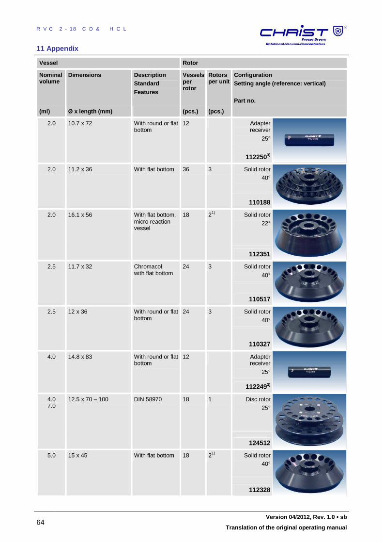
RVC 2-18 CD&HCL
11 Appendix
64 Version 04/2012, Rev. 1.0 • sb
Translation of the original operating manual
Vessel Rotor
Nominal volume
Dimensions Description Standard Features
Vessels per rotor
Rotors per unit
Configuration Setting angle (reference: vertical) Part no.
(ml) Ø x length (mm) (pcs.) (pcs.)
2.0 10.7 x 72 With round or flat bottom
12 Adapter receiver
25°
1122503)
2.0 11.2 x 36 With flat bottom 36 3 Solid rotor
40°
110188
2.0 16.1 x 56 With flat bottom, micro reaction vessel
18 21) Solid rotor
22°
112351
2.5 11.7 x 32 Chromacol, with flat bottom
24 3 Solid rotor
40°
110517
2.5 12 x 36 With round or flat bottom
24 3 Solid rotor
40°
110327
4.0 14.8 x 83 With round or flat bottom
12 Adapter receiver
25°
1122493)
4.0 7.0
12.5 x 70 – 100 DIN 58970 18 1 Disc rotor
25°
124512
5.0 15 x 45 With flat bottom 18 21) Solid rotor
40°
112328
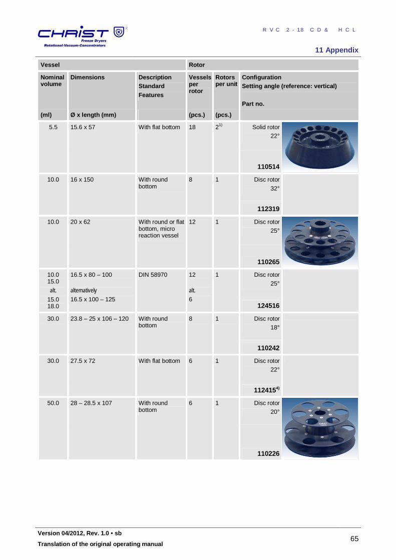
RVC 2-18 CD&HCL
11 Appendix
Version 04/2012, Rev. 1.0 • sb 65
Translation of the original operating manual
Vessel Rotor
Nominal volume
Dimensions Description Standard Features
Vessels per rotor
Rotors per unit
Configuration Setting angle (reference: vertical) Part no.
(ml) Ø x length (mm) (pcs.) (pcs.)
5.5 15.6 x 57 With flat bottom 18 21) Solid rotor
22°
110514
10.0 16 x 150 With round bottom
8 1 Disc rotor
32°
112319
10.0 20 x 62 With round or flat bottom, micro reaction vessel
12 1 Disc rotor
25°
110265
10.0 15.0
alt. 15.0 18.0
16.5 x 80 – 100
alternatively 16.5 x 100 – 125
DIN 58970 12
alt. 6
1 Disc rotor
25°
124516
30.0 23.8 – 25 x 106 – 120 With round bottom
8 1 Disc rotor
18°
110242
30.0 27.5 x 72 With flat bottom 6 1 Disc rotor
22°
1124154)
50.0 28 – 28.5 x 10⁷ With round bottom
6 1 Disc rotor
20°
110226
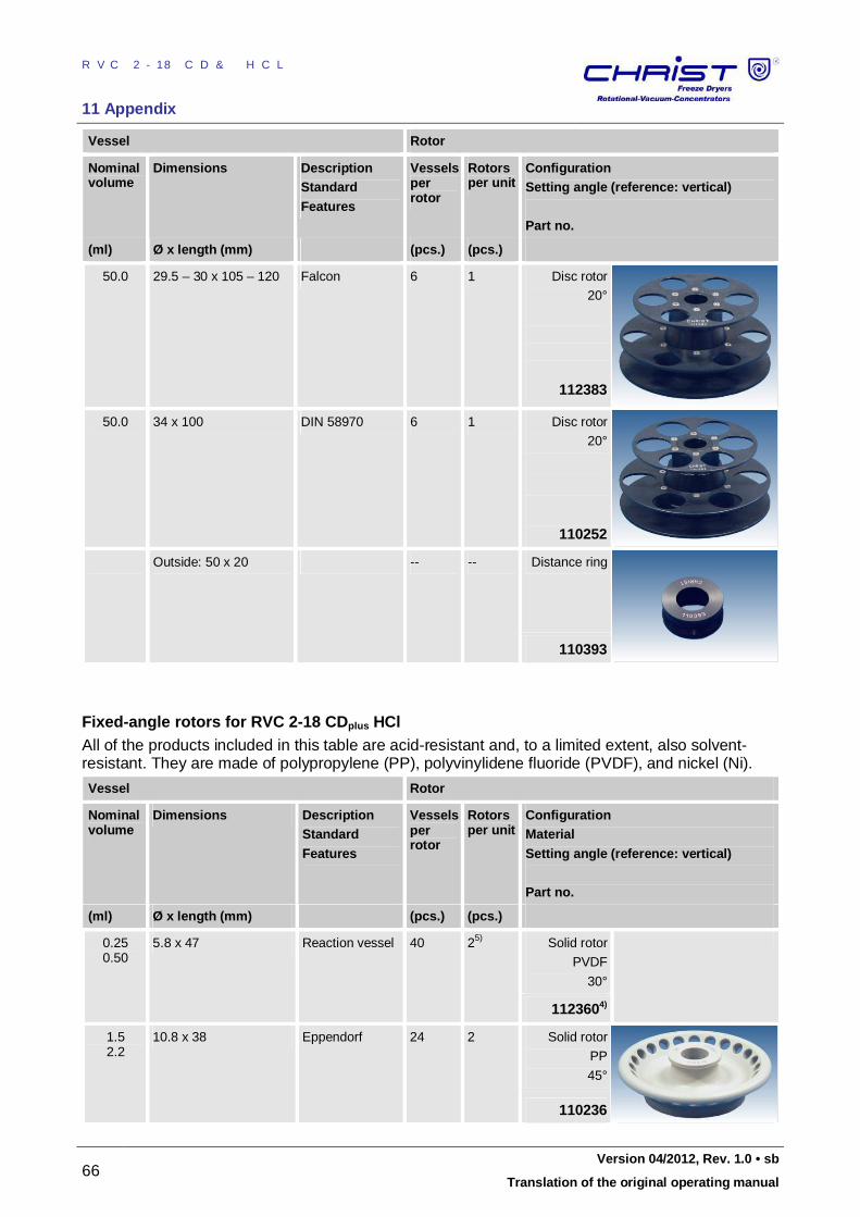
RVC 2-18 CD&HCL
11 Appendix
66 Version 04/2012, Rev. 1.0 • sb
Translation of the original operating manual
Vessel Rotor
Nominal volume
Dimensions Description Standard Features
Vessels per rotor
Rotors per unit
Configuration Setting angle (reference: vertical) Part no.
(ml) Ø x length (mm) (pcs.) (pcs.)
50.0 29.5 – 30 x 105 – 120 Falcon 6 1 Disc rotor
20°
112383
50.0 34 x 100 DIN 58970 6 1 Disc rotor
20°
110252
Outside: 50 x 20 -- -- Distance ring
110393
Fixed-angle rotors for RVC 2-18 CDplus HCl All of the products included in this table are acid-resistant and, to a limited extent, also solvent-resistant. They are made of polypropylene (PP), polyvinylidene fluoride (PVDF), and nickel (Ni).
Vessel Rotor
Nominal volume
Dimensions Description Standard Features
Vessels per rotor
Rotors per unit
Configuration Material Setting angle (reference: vertical) Part no.
(ml) Ø x length (mm) (pcs.) (pcs.)
0.25 0.50
5.8 x 47 Reaction vessel 40 25) Solid rotor
PVDF
30°
1123604)
1.5 2.2
10.8 x 38 Eppendorf 24 2 Solid rotor
PP
45°
110236
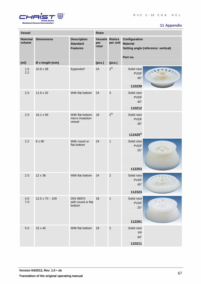
RVC 2-18 CD&HCL
11 Appendix
Version 04/2012, Rev. 1.0 • sb 67
Translation of the original operating manual
Vessel Rotor
Nominal volume
Dimensions Description Standard Features
Vessels per rotor
Rotors per unit
Configuration Material Setting angle (reference: vertical) Part no.
(ml) Ø x length (mm) (pcs.) (pcs.)
1.5 2.2
10.8 x 38 Eppendorf 24 25) Solid rotor
PVDF
45°
110239
2.0 11.6 x 32 With flat bottom 24 3 Solid rotor
PVDF
40°
110212
2.0 16.1 x 56 With flat bottom; micro meaction vessel
18 25) Solid rotor
PVDF
35°
1124254)
2.2 8 x 90 With round or flat bottom
24 1 Solid rotor
PVDF
25°
112253
2.5 12 x 36 With flat bottom 24 2 Solid rotor
PVDF
40°
112323
4.0 7.0
12.5 x 70 – 100 DIN 58970 with round or flat bottom
18 1 Solid rotor
PVDF
25°
112261
5.0 15 x 45 With flat bottom 18 2 Solid rotor
PP
40°
110211
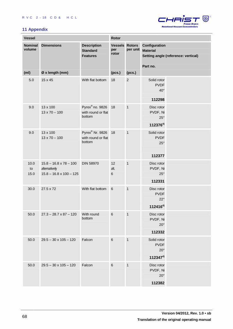
RVC 2-18 CD&HCL
11 Appendix
68 Version 04/2012, Rev. 1.0 • sb
Translation of the original operating manual
Vessel Rotor
Nominal volume
Dimensions Description Standard Features
Vessels per rotor
Rotors per unit
Configuration Material Setting angle (reference: vertical) Part no.
(ml) Ø x length (mm) (pcs.) (pcs.)
5.0 15 x 45 With flat bottom 18 2 Solid rotor
PVDF
40°
112298
9.0 13 x 100
13 x 70 – 100
Pyrex® no. 9826
with round or flat bottom
18 1 Disc rotor
PVDF, Ni
25°
1123764)
9.0 13 x 100
13 x 70 – 100
Pyrex® Nr. 9826
with round or flat bottom
18 1 Solid rotor
PVDF
25°
112377
10.0
to
15.0
15.8 – 16.8 x 78 – 100
alternatively 15.8 – 16.8 x 100 – 125
DIN 58970 12
alt. 6
1 Disc rotor
PVDF, Ni
25°
112331
30.0 27.5 x 72 With flat bottom 6 1 Disc rotor
PVDF
22°
1124164)
50.0 27.3 – 28.7 x 87 – 120 With round bottom
6 1 Disc rotor
PVDF, Ni
20°
112332
50.0 29.5 – 30 x 105 – 120 Falcon 6 1 Solid rotor
PVDF
20°
1123474)
50.0 29.5 – 30 x 105 – 120 Falcon 6 1 Disc rotor
PVDF, Ni
20°
112382
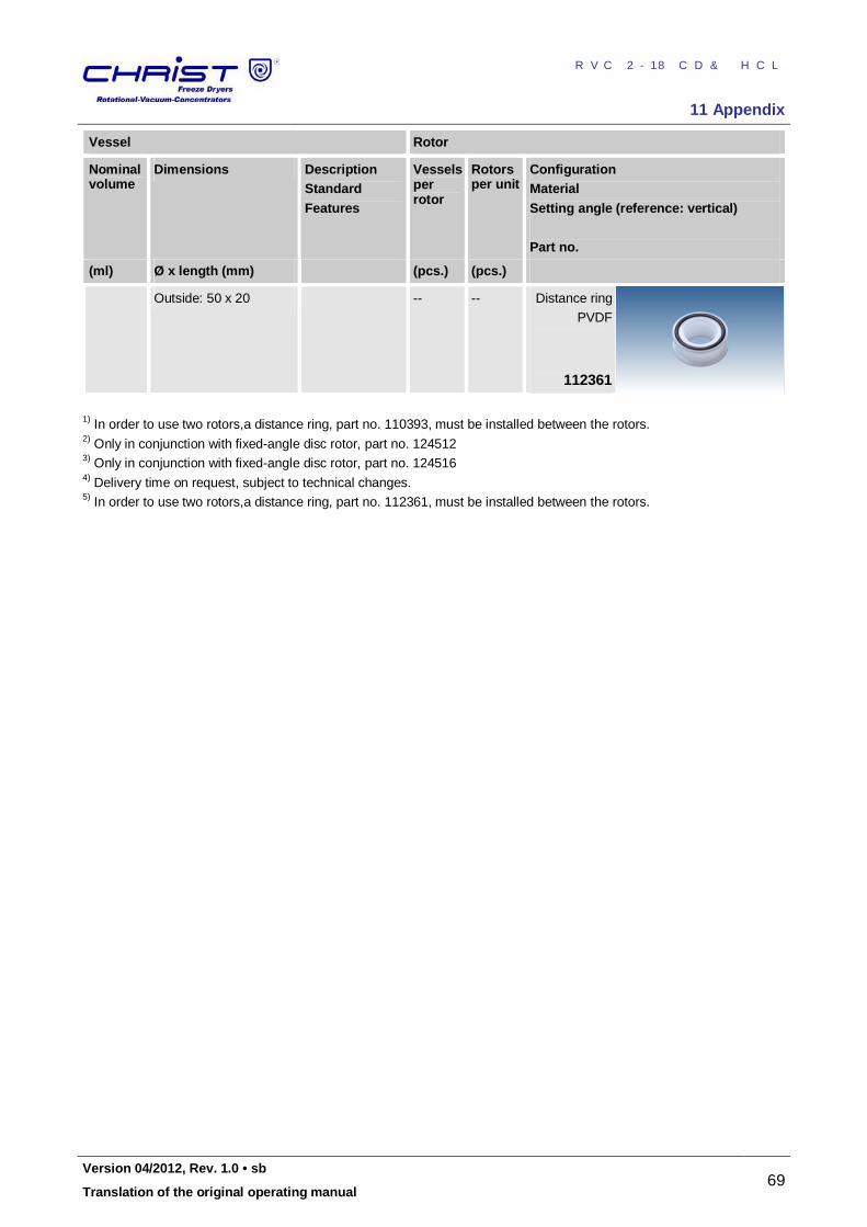
RVC 2-18 CD&HCL
11 Appendix
Version 04/2012, Rev. 1.0 • sb 69
Translation of the original operating manual
Vessel Rotor
Nominal volume
Dimensions Description Standard Features
Vessels per rotor
Rotors per unit
Configuration Material Setting angle (reference: vertical) Part no.
(ml) Ø x length (mm) (pcs.) (pcs.)
Outside: 50 x 20 -- -- Distance ring
PVDF
112361
1) In order to use two rotors,a distance ring, part no. 110393, must be installed between the rotors. 2) Only in conjunction with fixed-angle disc rotor, part no. 124512 3) Only in conjunction with fixed-angle disc rotor, part no. 124516 4) Delivery time on request, subject to technical changes. 5) In order to use two rotors,a distance ring, part no. 112361, must be installed between the rotors. Pos: 191 /01 0 Univ ersal mod ule/ Sei tenwe chsel @ 0\ mod _12 021 1624 431 2_0 .docx @ 1 05 @ 22 @ 1
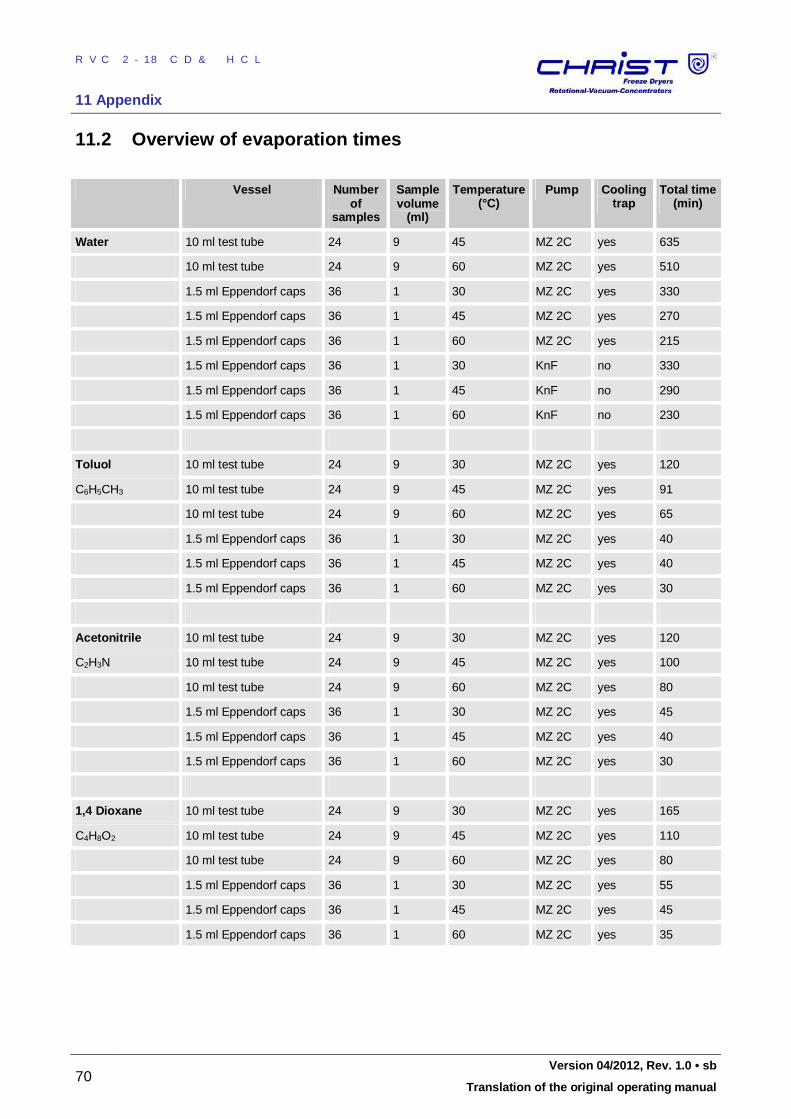
RVC 2-18 CD&HCL
11 Appendix
70 Version 04/2012, Rev. 1.0 • sb
Translation of the original operating manual
Pos: 192 /20 0 Ch rist/3 60 RVC-BA (S TANDARDMODULE) /11 0 Anha ng/ 110 -003 0 Ü bersic ht Abd am pfzeit en @ 8\m od_ 131 0103 584 670 _68 .docx @ 47 421 @ 2 2 @ 1
11.2 Overview of evaporation times
Vessel Number of
samples
Sample volume
(ml)
Temperature (°C)
Pump Cooling trap
Total time (min)
Water 10 ml test tube 24 9 45 MZ 2C yes 635
10 ml test tube 24 9 60 MZ 2C yes 510
1.5 ml Eppendorf caps 36 1 30 MZ 2C yes 330
1.5 ml Eppendorf caps 36 1 45 MZ 2C yes 270
1.5 ml Eppendorf caps 36 1 60 MZ 2C yes 215
1.5 ml Eppendorf caps 36 1 30 KnF no 330
1.5 ml Eppendorf caps 36 1 45 KnF no 290
1.5 ml Eppendorf caps 36 1 60 KnF no 230
Toluol 10 ml test tube 24 9 30 MZ 2C yes 120
C6H5CH3 10 ml test tube 24 9 45 MZ 2C yes 91
10 ml test tube 24 9 60 MZ 2C yes 65
1.5 ml Eppendorf caps 36 1 30 MZ 2C yes 40
1.5 ml Eppendorf caps 36 1 45 MZ 2C yes 40
1.5 ml Eppendorf caps 36 1 60 MZ 2C yes 30
Acetonitrile 10 ml test tube 24 9 30 MZ 2C yes 120
C2H3N 10 ml test tube 24 9 45 MZ 2C yes 100
10 ml test tube 24 9 60 MZ 2C yes 80
1.5 ml Eppendorf caps 36 1 30 MZ 2C yes 45
1.5 ml Eppendorf caps 36 1 45 MZ 2C yes 40
1.5 ml Eppendorf caps 36 1 60 MZ 2C yes 30
1,4 Dioxane 10 ml test tube 24 9 30 MZ 2C yes 165
C4H8O2 10 ml test tube 24 9 45 MZ 2C yes 110
10 ml test tube 24 9 60 MZ 2C yes 80
1.5 ml Eppendorf caps 36 1 30 MZ 2C yes 55
1.5 ml Eppendorf caps 36 1 45 MZ 2C yes 45
1.5 ml Eppendorf caps 36 1 60 MZ 2C yes 35
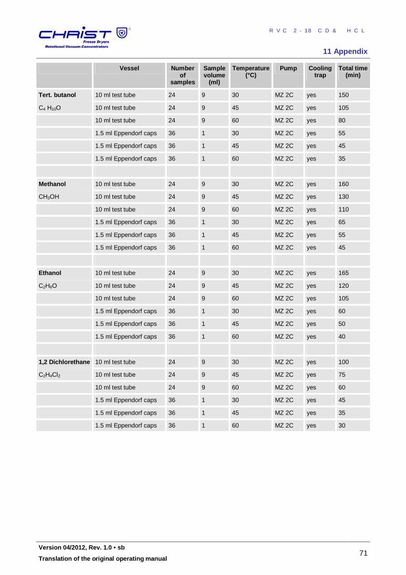
RVC 2-18 CD&HCL
11 Appendix
Version 04/2012, Rev. 1.0 • sb 71
Translation of the original operating manual
Vessel Number of
samples
Sample volume
(ml)
Temperature (°C)
Pump Cooling trap
Total time (min)
Tert. butanol 10 ml test tube 24 9 30 MZ 2C yes 150
C4 H10O 10 ml test tube 24 9 45 MZ 2C yes 105
10 ml test tube 24 9 60 MZ 2C yes 80
1.5 ml Eppendorf caps 36 1 30 MZ 2C yes 55
1.5 ml Eppendorf caps 36 1 45 MZ 2C yes 45
1.5 ml Eppendorf caps 36 1 60 MZ 2C yes 35
Methanol 10 ml test tube 24 9 30 MZ 2C yes 160
CH3OH 10 ml test tube 24 9 45 MZ 2C yes 130
10 ml test tube 24 9 60 MZ 2C yes 110
1.5 ml Eppendorf caps 36 1 30 MZ 2C yes 65
1.5 ml Eppendorf caps 36 1 45 MZ 2C yes 55
1.5 ml Eppendorf caps 36 1 60 MZ 2C yes 45
Ethanol 10 ml test tube 24 9 30 MZ 2C yes 165
C2H6O 10 ml test tube 24 9 45 MZ 2C yes 120
10 ml test tube 24 9 60 MZ 2C yes 105
1.5 ml Eppendorf caps 36 1 30 MZ 2C yes 60
1.5 ml Eppendorf caps 36 1 45 MZ 2C yes 50
1.5 ml Eppendorf caps 36 1 60 MZ 2C yes 40
1,2 Dichlorethane 10 ml test tube 24 9 30 MZ 2C yes 100
C2H4Cl2 10 ml test tube 24 9 45 MZ 2C yes 75
10 ml test tube 24 9 60 MZ 2C yes 60
1.5 ml Eppendorf caps 36 1 30 MZ 2C yes 45
1.5 ml Eppendorf caps 36 1 45 MZ 2C yes 35
1.5 ml Eppendorf caps 36 1 60 MZ 2C yes 30 Pos: 193 /01 0 Univ ersal mod ule/ Sei tenwe chsel @ 0\ mod _12 021 1624 431 2_0 .docx @ 1 05 @ 2 @ 1
RVC 2-18 CD&HCL
11 Appendix
72 Version 04/2012, Rev. 1.0 • sb
Translation of the original operating manual
Pos: 194 /20 0 Ch rist/3 61 RVC-BA (PROJEK TE)/RVC 2- 18 CD plus_ 2-1 8 CDplus _HCl/11 0 Anh ang/ 110 -00 41 Kurzb edie nun gsanl eitun g HCl @ 12\m od_ 133 542 656 832 9_68 .docx @ 6 405 8 @ 2 2 @ 1
11.3 Brief operating instructions 1. Switch the system on via the mains power switch on the right side of the
unit. 2. Switch the vacuum pump and/or the cooling trap on. 3. Close the lid. 4. Starting the warm-up phase:
• Enter the set values for the warm-up phase into "menu" "options" "timer warm-up" and "temperature warm-up". Confirm your
entries and quit the menu. • Press the left-hand function key "mode". • Select the "warm-up" menu and confirm. • Open the lid when the warm-up phase has ended. • Install the rotors and close the lid.
5. Changing the set values for time, temperature, vacuum and safety pressure: • Select "menu" with the right-hand function key. • Select "change set values for manual mode" from the main menu. • Select the set value with the aid of the up/down keys and confirm
with the right-hand function key "edit". • Change the set value with the aid of the up/down keys and confirm
with the right-hand function key "ok". • Quit the menu with the left-hand function key.
6. Starting the process "evaporation manual": • Open the "mode" menu with the left-hand function key. • Select "evaporation manual" using the up/down keys. • Start the evaporation process by pressing the right-hand function
key. The start of the evaporation process starts the following automatic process run: • The rotor speed increases (direction of rotation: anti-clockwise). • At 70% of the selected maximum speed: the aeration valve closes
automatically (to avoid boiling retardation).
• At 80% of the selected maximum speed: the stop valve opens the connection to the vacuum pump.
• Further speed increase until the preselected maximum rotor speed is reached.
7. Interrupting an evaporation process: • Press the left-hand function key "mode". • Select "stop evaporation" and confirm with the right-hand function
key. Without an interruption, the evaporation process ends after the preselected time. The following process runs automatically: • At maximum speed: the stop valve closes the connection to the
vacuum pump, the aeration valve opens; the rotor speed is maintained for 30 sec (aeration phase, to avoid boiling retardation).
• The rotor decelerates until it is at a standstill. After the standstill of the rotor the lid can be opened in order to remove the rotors.
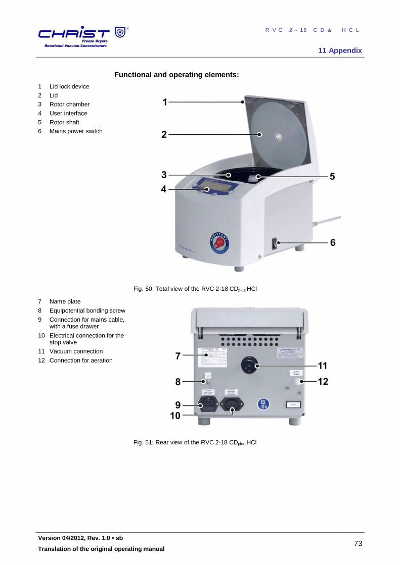
RVC 2-18 CD&HCL
11 Appendix
Version 04/2012, Rev. 1.0 • sb 73
Translation of the original operating manual
Functional and operating elements:
1 Lid lock device
2 Lid
3 Rotor chamber
4 User interface
5 Rotor shaft
6 Mains power switch
Fig. 50: Total view of the RVC 2-18 CDplus HCl
7 Name plate
8 Equipotential bonding screw
9 Connection for mains cable, with a fuse drawer
10 Electrical connection for the stop valve
11 Vacuum connection
12 Connection for aeration
Fig. 51: Rear view of the RVC 2-18 CDplus HCl
Pos: 195 /01 0 Univ ersal mod ule/ Sei tenwe chsel @ 0\ mod _12 021 1624 431 2_0 .docx @ 1 05 @ 2 @ 1
RVC 2-18 CD&HCL
11 Appendix
74 Version 04/2012, Rev. 1.0 • sb
Translation of the original operating manual
Pos: 196 /20 0 Ch rist/3 61 RVC-BA (PROJEK TE)/RVC 2- 18 CD plus_ 2-1 8 CDplus _HCl/11 0 Anh ang/ 110 -00 51 Konfo rmit ätse rklär ung HCl @ 1 2\m od_1 335 426 848 094 _68. docx @ 64 066 @ 22 @ 1
11.4 EC-declaration of conformity
Pos: 197 /01 0 Univ ersal mod ule/ Sei tenwe chsel @ 0\ mod _12 021 1624 431 2_0 .docx @ 1 05 @ 2 @ 1
RVC 2-18 CD&HCL
12 Glossary
Version 04/2012, Rev. 1.0 • sb 75
Translation of the original operating manual
Pos: 198 /01 0 Univ ersal mod ule/9 01 Gl ossa r RVC== == === == == == === == == === == == === == == = @ 8 \mo d_1 309 930 672 666_ 68. docx @ 47 101 @ 21 @ 1
12 Glossary Boiling retardation The temperature of a liquid can rise above the boiling point without the liquid actually starting to boil. Vibrations or shocks quickly lead to the formation of a large gas bubble that escapes explosively from the vessel. This phenomenon is known as boiling retardation. It occurs when neither the liquid nor the wall of the vessel include any condensation nuclei at which vapour bubbles might form. Pressure increase test The pressure increase test is used to determine whether the evaporation in the rotor chamber is complete. During the pressure increase test, the rotor chamber is separated from the cooling trap or vacuum pump by way of the stop valve. The system evaluates the pressure increase that is caused by any additionally released steam. In order to perform the pressure increase test, limits for the pressure increase as well as the test duration must be defined beforehand. Relative centrifugal force The relative centrifugal force is the acceleration that the samples are subjected to during the rotation. The acceleration is stated as a multiple of the mean gravitational acceleration g. It can be increased by increasing the radius inside the rotor chamber and by increasing the speed. These three parameters are interdependent and linked with each other via the following formula: Relative centrifugal force RCF = 11.18 x 10⁻⁶ x r x n2 r = radius in cm n = speed in rpm
RCF without any dimension
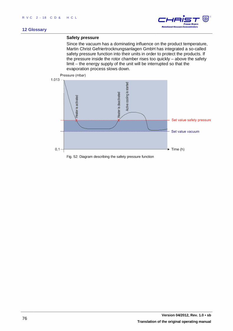
RVC 2-18 CD&HCL
12 Glossary
76 Version 04/2012, Rev. 1.0 • sb
Translation of the original operating manual
Safety pressure Since the vacuum has a dominating influence on the product temperature, Martin Christ Gefriertrocknungsanlagen GmbH has integrated a so-called safety pressure function into their units in order to protect the products. If the pressure inside the rotor chamber rises too quickly – above the safety limit – the energy supply of the unit will be interrupted so that the evaporation process slows down.
Fig. 52: Diagram describing the safety pressure function
=== E nde der Liste für Tex tma rke I nhal t = ==
RVC 2-18 CD&HCL
13 Index
Version 04/2012, Rev. 1.0 • sb 77
Translation of the original operating manual
13 Index
A
Accessories ........................................... 9, 17 Accessories, cleaning and care .................. 56 Accident prevention ................................... 16 Active phases ............................................ 36 Advantages of the rotational vacuum
concentration .......................................... 13 Aeration valve ...................................... 24, 62 Aluminium accessories .............................. 58 Aluminium accessories, cleaning and care. 56 Aluminium rotor .......................................... 58 Ambient conditions ..................................... 62 Ambient temperature ................................. 62 Assignment of the function keys ................. 35 Autoclaving the accessories ....................... 58
B
BASIC Withdrawal of the vapours by a vacuum
pump ................................................... 25 Boiling retardation ...................................... 75 Brief operating instructions ......................... 72 Bucket ........................................................ 33
C
Care of the accessories ............................. 56 CDplus control system ................................. 34 CE mark in compliance with the directive
2006/42/EC ...................................... 11, 14 Chamber overtemperature ......................... 44 Change display contrast............................. 41 Changing the set values for the manual mode
............................................................... 39 Chemical and biological safety ................... 18 Circuit diagrams ......................................... 62 Cleaning agents ......................................... 50 Cleaning of the rotor chamber .................... 51 Cleaning the rotational vacuum concentrator
............................................................... 50 Cleaning the RVC and the accessories ...... 50 Click at button push ................................... 42 Closing the lid ............................................ 29 Commissioning ............................................ 9
Condensation of the vapours in a cooling trap with distributor block ............................... 27
Condensation of the vapours in a cooling trap with distributor block and two RVCs ....... 28
Condensation of the vapours in a glass cooling trap ............................................. 26
Connected load .......................................... 61 Connection................................................. 23 Connection of a vacuum pump and/or a
cooling trap ............................................. 25 Continuous operation vacuum pump .......... 42 Copyright ..................................................... 8 Corrosion ................................. 32, 50, 51, 56 Country of origin......................................... 11 Cracks ....................................................... 56 Customer-provided fuses ........................... 23
D
Damage to the ball bearings ................ 51, 53 Dangerous goods....................................... 19 Dangerous materials .................................. 57 Declaration of conformity ........................... 74 Declaration of decontamination .................. 60 Dimensions and weight .............................. 21 Dimensions of the rotor chamber ............... 62 Dimensions of the unit................................ 62 Direct hazard to the life and health ............. 15 Disinfection of the rotor chamber and
accessories ............................................ 57 Display ....................................................... 34 Disposal of the packaging .......................... 61 Disposal of the RVC ................................... 61
E
Earth conductor check ............................... 19 EC declaration of conformity ........................ 8 EC-declaration of conformity ...................... 74 Electrical connection .................................. 61 Electrical connection for the stop valve ...... 10 Electrical safety .......................................... 17 EMC according to EN 55011 ...................... 62 Emergency lid release................................ 46 Emissions .................................................. 18 Equipment connection................................ 62
RVC 2-18 CD&HCL
13 Index
78 Version 04/2012, Rev. 1.0 • sb
Translation of the original operating manual
equipotential bonding screw ....................... 19 Equipotential bonding screw ................ 10, 23 Error correction .......................................... 44 Error messages.................................... 19, 44 Evaporation with different tube sizes .......... 31 Evaporation with low capacity .................... 31 Examples of use ........................................ 13 Explanation of symbols ................................ 8 Explanation of the symbols and notes ........ 15 Extended service menu.............................. 42
F
Factory settings loaded .............................. 45 Fire prevention ........................................... 18 Fixed-angle rotors ................................ 63, 66 Form for the return of defective parts ......... 60 Function keys ............................................. 34 Functional elements ................................... 10 Fuse drawer ......................................... 10, 73 Fuses ......................................................... 18
G
General conditions ....................................... 7 General malfunctions ................................. 44 Glass breakage .......................................... 57 Glass tubes ................................................ 58
H
Hazard warnings .................................... 7, 29 High temperature resolution ....................... 42 Highly corrosive substances ...................... 17
I
Imbalance ............................................ 19, 29 Importance of the operating manual ............. 7 Important information ................................. 15 Infectious substances ................................ 18 Inflammable substances ............................ 18 Informal safety instructions ........................ 16 Information status ...................................... 40 Initial start-up ............................................. 29 Installation of accessories .......................... 31 Installation of angle rotors .......................... 29 Installation of rotors and accessories ......... 29 Installation of swing-out rotors.................... 30 Installation site ........................................... 23 Intended use ................................................ 7
Interference suppression ............................ 11 IO communication error.............................. 45 IP code ...................................................... 61
L
Layout of the RVC ...................................... 10 Lid cannot be opened ................................ 44 Lid contacts error ....................................... 44 Lid lock device ........................................... 19 Lid status ................................................... 35 Load default settings .................................. 42
M
Main menu ................................................. 38 Mains fuse ................................................. 61 Mains input ................................................ 62 Mains power failure .................................... 45 Mains power switch .................................... 29 Maintenance .............................................. 50 Maintenance and service ........................... 50 Malfunctions ............................................... 44 Manual evaporation ................................... 38 Manufacturer .......................11, 18, 19, 50, 61 Marking of the unit ..................................... 14 Max. current consumption .......................... 61 Max. density of material at process start .... 61 Max. humidity ............................................. 62 Max. lid opening angle ............................... 62 Max. permissible imbalance ....................... 61 Measures in the event of hazards and
accidents ................................................ 20 Mechanical safety ...................................... 17 Mode.......................................................... 36 Mode of operation ...................................... 12
N
Name plate .............................. 10, 11, 17, 23 Noise level according to DIN 45635 ........... 62 Nominal rotor speed not reached ............... 45 Nominal voltage ................................... 11, 17 Notes on safety and hazards........................ 7
O
Online download of forms .......................... 60 Online service request ............................... 59 On-site transport ........................................ 22 Opening the lid ..................................... 29, 37
RVC 2-18 CD&HCL
13 Index
Version 04/2012, Rev. 1.0 • sb 79
Translation of the original operating manual
Operating elements .................................... 10 Operating mode ......................................... 36 Operating personnel .................................. 16 Operating voltage....................................... 23 Options ...................................................... 41 Order number ............................................ 61 Overview of evaporation times ................... 70
P
Packaging .................................................. 21 Packaging, disposal ................................... 61 Part number ............................................... 11 Pathogenic substances .............................. 18 Pending information ................................... 36 Performance data ...................................... 61 Permissible imbalance exceeded ............... 44 Physical data ............................................. 62 Pivotal point ............................................... 33 Potential hazard to the life and health ........ 15 Potentially hazardous situation................... 15 Power consumption ................................... 61 Power cord................................................. 17 Power failure safety ................................... 19 Power rating ............................................... 11 Power supply ............................................. 23 Pressure increase test ............................... 75 Pressure marks .......................................... 56 Prevention of accidents .......................... 7, 16 Principle of the rotational vacuum
concentration .......................................... 12 Process and equipment information ........... 40 Process messages ..................................... 45 PROFESSIONAL TWIN: Condensation of the
vapours in a cooling trap with distributor block and two RVCs ............................... 28
PROFESSIONAL: Condensation of the vapours in a cooling trap with distributor block ....................................................... 27
Protection class.......................................... 61 Protection of the environment .................... 16
R
Radioactive substances ............................. 18 Rated current ............................................. 11 Registered office ........................................ 11 Relative centrifugal force ............................ 61 Remaining hazards .................................... 20
Remove the glass particles and the metal dust from the rotor chamber ................... 57
Responsibility of the operator ..................... 16 Return of defective parts ............................ 60 Risk of burns .............................................. 37 Rotor blocks ............................................... 32 Rotor chamber ........................................... 51 Rotor overtemperature ............................... 44 Rotor program ............................................ 63 Rotor speed ............................................... 42
S
Safety area ................................................ 19 Safety class ......................................... 17, 23 Safety data sheets ..................................... 62 Safety devices ........................................... 19 Safety distance .............................. 17, 19, 23 Safety instructions .................................. 7, 29 Safety instructions for evaporation ............. 19 Safety pressure .......................................... 76 Safety pressure not reached ...................... 45 Safety-conscious work ............................... 16 Scope of supply ........................................... 8 Select language ......................................... 41 Serial number ................................ 11, 49, 59 Service ....................................................... 59 Service contact .......................................... 49 Service life ........................................... 50, 56 Service life of the accessories .................... 58 Service menu ............................................. 42 Service request .......................... 3, 49, 59, 62 Settings ...................................................... 41 Set-up and connection ............................... 23 Signs of corrosion ...................................... 56 Small flange connections ........................... 48 Solvents. .................................................... 50 Specialist personnel ................................... 59 Speed ........................................................ 61 STANDARD: Condensation of the vapours in
a glass cooling trap ................................ 26 Standards and regulations ........................... 8 Status bar .................................................. 35 Stop valve .................................................. 62 Stop valve connection ................................ 61 Stop valve, electrical connection ................ 10
RVC 2-18 CD&HCL
13 Index
80 Version 04/2012, Rev. 1.0 • sb
Translation of the original operating manual
Stopping the evaporation process prematurely ............................................ 38
Stopping the warm-up phase prematurely .. 37 Storage and transport ................................ 21 Storage conditions ..................................... 21 Stress-corrosion ......................................... 56 Supply voltage ........................................... 23 Surface temperature ............................ 18, 37 Susceptibility to corrosion .......................... 56 Switching the RVC off ................................ 43 Switching the RVC on ................................ 29 System check ............................................ 19 System messages ...................................... 45
T
Technical data ........................................... 61 Technical documentation ........................... 62 Teflon tubes ............................................... 58 Temperature ........................................ 39, 61 Temperature warm-up................................ 42 Thermal safety ........................................... 18 Thermal stress ..................................... 23, 50 Timer Evaporation ...................................... 39 Timer Heating ............................................ 39 Timer warm-up ........................................... 42 Toxic substances ....................................... 18
Transport safety device .............................. 22 Tubes ......................................................... 32 Type..................................................... 11, 61 Type of the RVC ........................................ 59
U
Up and down keys ..................................... 34 User interface ............................................ 34 UV radiation ......................................... 23, 50
V
Vacuum connection ............................. 10, 62 Vacuum connections .................................. 24 Values window ........................................... 35 Vapour pressure curve for ice and water .... 12 Ventilation .................................................. 23 Visible damage of the surface .................... 56 VSK3000 calibration error .......................... 44
W
Warm-up .................................................... 37 Warranty and liability .................................... 7 Weight ....................................................... 62 Withdrawal of the vapours by a vacuum
pump ...................................................... 25
Y
Year of manufacture .................................. 11