Operating Manual ALTAIR 4X - Sure-Safe · MSA Declaration of Conformity GB ALTAIR 4X 3 Declaration...
68
Operating Manual ALTAIR 4X Multigas Detector Order No. 10106503/01
-
Upload
vuongthuan -
Category
Documents
-
view
231 -
download
0
Transcript of Operating Manual ALTAIR 4X - Sure-Safe · MSA Declaration of Conformity GB ALTAIR 4X 3 Declaration...

Operating Manual
ALTAIR 4XMultigas Detector
Order No. 10106503/01

MSA AUER GmbHThiemannstrasse 1D-12059 Berlin
Germany
© MSA AUER GmbH. All rights reserved

Declaration of ConformityMSA
ALTAIR 4XGB 3
Declaration of Conformity
Manufactured by: Mine Safety Appliances Company
1000 Cranberry Woods Drive
Cranberry Township, PA 16066 USA
European authorized representative:
MSA AUER GmbH
Thiemannstrasse 1
D-12059 BerlinWe declare that the
MSA ALTAIR 4X
complies with the provisions of the council directive 94/9/EC [ATEX].This declaration is based on the EC-Type Examination Certificate FTZU 07 ATEX 0169 X in accordance with Annex III of the ATEX Directive 94/9/EC. Quality Assurance Notification issued by Ineris, Notified Body number 0080, in accordance with Annex IV of the ATEX Directive 94/9/EC.
We additionally declare that this product is in conformance with the EMC Directive 2004/108/EC in accordance with the standards
EN 50270:2006 Type 2 and EN 61000-6-3:2007
The product is in conformance with the directive 2010/68 EC, [MarED]:
EC-Type Examination Certificate: 213.048 Notified Body number: 0736
MSA AUER GmbH
Dr. Axel Schubert
R&D Instruments
Berlin, April 2011
MSAContents
ALTAIR 4X4 GB
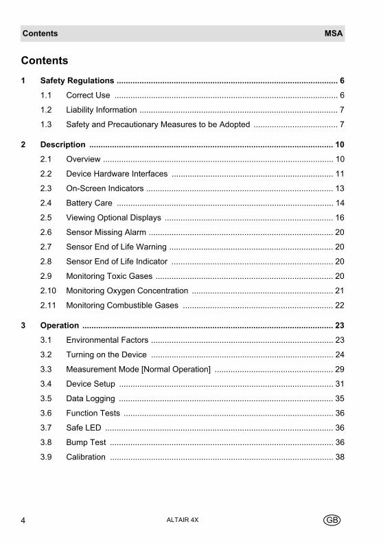
Contents
1 Safety Regulations ................................................................................................. 6
1.1 Correct Use .................................................................................................. 6
1.2 Liability Information ....................................................................................... 7
1.3 Safety and Precautionary Measures to be Adopted ..................................... 7
2 Description ........................................................................................................... 10
2.1 Overview ..................................................................................................... 10
2.2 Device Hardware Interfaces ....................................................................... 11
2.3 On-Screen Indicators .................................................................................. 13
2.4 Battery Care ............................................................................................... 14
2.5 Viewing Optional Displays .......................................................................... 16
2.6 Sensor Missing Alarm ................................................................................. 20
2.7 Sensor End of Life Warning ........................................................................ 20
2.8 Sensor End of Life Indicator ....................................................................... 20
2.9 Monitoring Toxic Gases .............................................................................. 20
2.10 Monitoring Oxygen Concentration .............................................................. 21
2.11 Monitoring Combustible Gases .................................................................. 22
3 Operation .............................................................................................................. 23
3.1 Environmental Factors ................................................................................ 23
3.2 Turning on the Device ................................................................................ 24
3.3 Measurement Mode [Normal Operation] .................................................... 29
3.4 Device Setup .............................................................................................. 31
3.5 Data Logging .............................................................................................. 35
3.6 Function Tests ............................................................................................ 36
3.7 Safe LED .................................................................................................... 36
3.8 Bump Test .................................................................................................. 36
3.9 Calibration .................................................................................................. 38
ContentsMSA
ALTAIR 4XGB 5
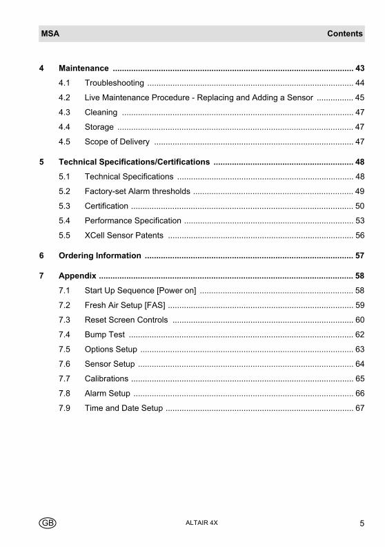
4 Maintenance ......................................................................................................... 43
4.1 Troubleshooting .......................................................................................... 44
4.2 Live Maintenance Procedure - Replacing and Adding a Sensor ................ 45
4.3 Cleaning ..................................................................................................... 47
4.4 Storage ....................................................................................................... 47
4.5 Scope of Delivery ....................................................................................... 47
5 Technical Specifications/Certifications ............................................................. 48
5.1 Technical Specifications ............................................................................. 48
5.2 Factory-set Alarm thresholds ...................................................................... 49
5.3 Certification ................................................................................................. 50
5.4 Performance Specification .......................................................................... 53
5.5 XCell Sensor Patents ................................................................................. 56
6 Ordering Information ........................................................................................... 57
7 Appendix ............................................................................................................... 58
7.1 Start Up Sequence [Power on] ................................................................... 58
7.2 Fresh Air Setup [FAS] ................................................................................. 59
7.3 Reset Screen Controls ............................................................................... 60
7.4 Bump Test .................................................................................................. 62
7.5 Options Setup ............................................................................................. 63
7.6 Sensor Setup .............................................................................................. 64
7.7 Calibrations ................................................................................................. 65
7.8 Alarm Setup ................................................................................................ 66
7.9 Time and Date Setup .................................................................................. 67

MSASafety Regulations
ALTAIR 4X6 GB
1 Safety Regulations
1.1 Correct Use
The ALTAIR 4X Multigas Detector is intended for use by trained and qualified per-sonnel. It is designed to be used when performing a hazard assessment to:
- assess potential worker exposure to combustible and toxic gases and vapours as well as low level of oxygen.
- determine the appropriate gas and vapour monitoring needed for a workplace.
The ALTAIR 4X Multigas Detector can be equipped to detect:
- Combustible gases and certain combustible vapours
- Oxygen-deficient or oxygen-rich atmospheres
- Specific toxic gases for which a sensor is installed.
It is imperative that this operating manual be read and observed when using the product. In particular, the safety instructions, as well as the information for the use and operation of the product, must be carefully read and observed. Furthermore, the national regulations applicable in the user's country must be taken into account for a safe use.
Alternative use, or use outside this specification will be considered as non-compli-ance. This also applies especially to unauthorised alterations to the product and to commissioning work that has not been carried out by MSA or authorised persons.
While the device can detect up to 30 % oxygen in ambient air, it is approved for use only up to 21 % oxygen.
Danger!
This product is supporting life and health. Inappropriate use, mainte-nance or servicing may affect the function of the device and thereby se-riously compromise the user's life.
Before use the product operability must be verified. The product must not be used if the function test is unsuccessful, it is damaged, a compe-tent servicing/maintenance has not been made, genuine MSA spare parts have not been used.
Safety RegulationsMSA
ALTAIR 4XGB 7
1.2 Liability Information
MSA accepts no liability in cases where the product has been used inappropriately or not as intended. The selection and use of the product are the exclusive respon-sibility of the individual operator.
Product liability claims, warranties also as guarantees made by MSA with respect to the product are voided, if it is not used, serviced or maintained in accordance with the instructions in this manual.
1.3 Safety and Precautionary Measures to be Adopted
Check function each day before use
Before each use, check the function and calibration of the device. Otherwise there is a danger that incorrect results will be displayed. The check is performed using a suitable calibration gas.
Perform a bump test each day before use
Perform a bump test before each day's use to verify proper operation. The device must pass the bump test. If it fails the test, perform a calibration before using the device.
Perform a bump test more frequently if the device is subjected to physical shock or high levels of contaminants. Also, perform a bump test more frequently if the tested atmosphere contains the following materials, which may desensitize the combusti-ble gas sensor and reduce its readings:
- Organic silicones
- Silicates
- Lead-containing compounds
- Hydrogen sulphide exposures over 200 ppm or exposures over 50 ppm for one minute.
Check minimum concentration of a combustible gas
The minimum concentration of a combustible gas in air that can ignite is defined as the Lower Explosive Limit [LEL]]. A combustible gas reading of "XXX” indicates the atmosphere is above 100 % LEL or 5.00 % vol CH4, and an explosion hazard ex-ists. Move away from hazardous area immediately.
Attention!
The following safety instructions must be observed implicitly. Only in this way can the safety and health of the individual operators, and the correct functioning of the device, be guaranteed.
MSASafety Regulations
ALTAIR 4X8 GB
Observe atmosphere
Do not use the device to test for combustible or toxic gases in the following atmos-pheres as this may result in erroneous readings:
- Oxygen-deficient or oxygen-rich atmospheres
- Reducing atmospheres
- Furnace stacks
- Inert environments
- Atmospheres containing combustible airborne mists/dusts.
Use the device only to detect gases/vapours for which a sensor is installed.
Make sure adequate oxygen is present.
Not to be used for gases having a flashpoint in excess of 38 °C
Do not use the device to test for combustible gases in atmospheres containing va-pours from liquids with a high flash point [above 38 °C], as this may result in erro-neously low readings.
Physical shock
Recheck calibration if device is subjected to physical shock.
Sensor maintenance
Do not block sensor openings as this may cause inaccurate readings. Do not press on the face of the sensors, as this may damage them and cause erroneous read-ings. Do not use compressed air to clean the sensor holes, as the pressure may damage the sensors.
Observe proper time for diplay stabilising
Allow sufficient time for device to display accurate reading. Response times vary based on the type of sensor being utilized.
Observe proper battery maintenance
Use only battery chargers made available by MSA for use with this device; other chargers may damage the battery pack and the device. Dispose of in accordance with local health and safety regulations.
Use of the GALAXY Automated Test System is an alternate approved method for charging ALTAIR 4X devices.
Safety RegulationsMSA
ALTAIR 4XGB 9
Be aware of environmental conditions
A number of environmental factors may affect the sensor readings, including changes in pressure, humidity and temperature.
Pressure and humidity changes also affect the amount of oxygen actually present in the atmosphere.
Be aware of the procedures for handling electrostatically sensitive electronics
The device contains electrostatically sensitive components. Do not open or repair the device without using appropriate electrostatic discharge [ESD] protection. The warranty does not cover damage caused by electrostatic discharges.
Be aware of the product regulations
Follow all relevant national regulations applicable in the country of use.
Be aware of the warranty regulations
The warranties made by Mine Safety Appliances Company with respect to the prod-uct are voided if the product is not used and maintained in accordance with the in-structions in this manual. Please protect yourself and others by following them. We encourage our customers to write or call regarding this equipment prior to use or for any additional information relative to use or service.
MSADescription
ALTAIR 4X10 GB
2 Description
2.1 Overview
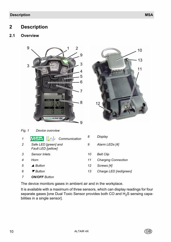
Fig. 1 Device overview
The device monitors gases in ambient air and in the workplace.
It is available with a maximum of three sensors, which can display readings for four separate gases [one Dual Toxic Sensor provides both CO and H2S sensing capa-bilities in a single sensor].
1 Communication8 Display
2 Safe LED [green] and Fault LED [yellow]
9 Alarm LEDs [4]
3 Sensor Inlets 10 Belt Clip
4 Horn 11 Charging Connection
5 Button 12 Screws [4]
6 Button 13 Charge LED [red/green]
7 ON/OFF Button
9
9
1 2
9
3
456
7
8
311
10
12
13
DescriptionMSA
ALTAIR 4XGB 11
The alarm levels for the individual gases are factory-set and can be changed through the Setup Menu. These changes can also be made through MSA Link soft-ware. Ensure that the latest version of the MSA Link software has been downloaded from MSA’s website www.msanet.com.
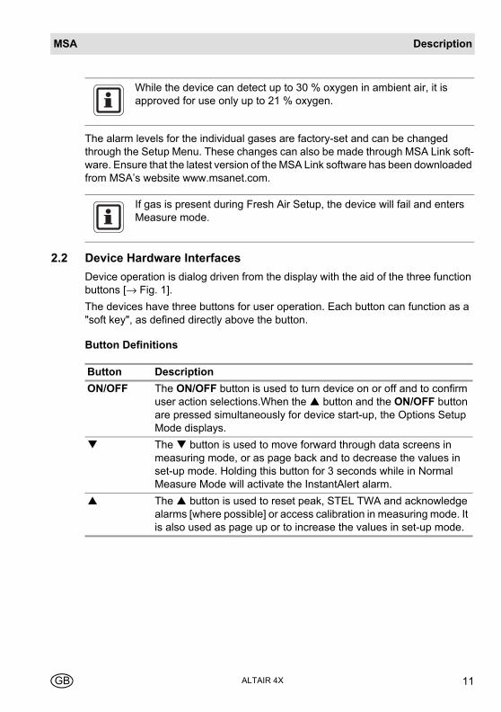
2.2 Device Hardware Interfaces
Device operation is dialog driven from the display with the aid of the three function buttons [→ Fig. 1].
The devices have three buttons for user operation. Each button can function as a "soft key", as defined directly above the button.
Button Definitions
While the device can detect up to 30 % oxygen in ambient air, it is approved for use only up to 21 % oxygen.
If gas is present during Fresh Air Setup, the device will fail and enters Measure mode.
Button Description
ON/OFF The ON/OFF button is used to turn device on or off and to confirm user action selections.When the button and the ON/OFF button are pressed simultaneously for device start-up, the Options Setup Mode displays.
The button is used to move forward through data screens in measuring mode, or as page back and to decrease the values in set-up mode. Holding this button for 3 seconds while in Normal Measure Mode will activate the InstantAlert alarm.
The button is used to reset peak, STEL TWA and acknowledge alarms [where possible] or access calibration in measuring mode. It is also used as page up or to increase the values in set-up mode.
MSADescription
ALTAIR 4X12 GB
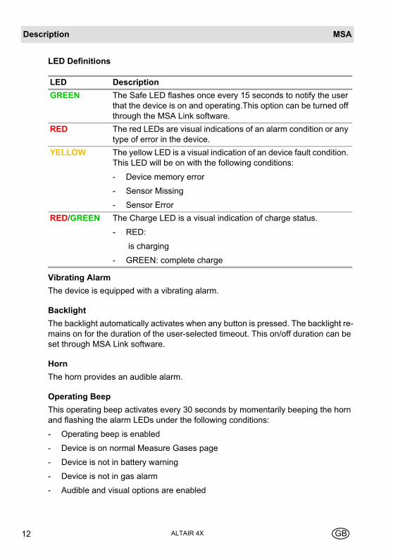
LED Definitions
Vibrating Alarm
The device is equipped with a vibrating alarm.
Backlight
The backlight automatically activates when any button is pressed. The backlight re-mains on for the duration of the user-selected timeout. This on/off duration can be set through MSA Link software.
Horn
The horn provides an audible alarm.
Operating Beep
This operating beep activates every 30 seconds by momentarily beeping the horn and flashing the alarm LEDs under the following conditions:
- Operating beep is enabled
- Device is on normal Measure Gases page
- Device is not in battery warning
- Device is not in gas alarm
- Audible and visual options are enabled
LED Description
GREEN The Safe LED flashes once every 15 seconds to notify the user that the device is on and operating.This option can be turned off through the MSA Link software.
RED The red LEDs are visual indications of an alarm condition or any type of error in the device.
YELLOW The yellow LED is a visual indication of an device fault condition. This LED will be on with the following conditions:
- Device memory error
- Sensor Missing
- Sensor Error
RED/GREEN The Charge LED is a visual indication of charge status.
- RED:
is charging
- GREEN: complete charge

DescriptionMSA
ALTAIR 4XGB 13
2.3 On-Screen Indicators
Fig. 2 Display
1 Graphic Symbols 3 Gas Concentration
2 Gas Type
Alarm Symbol – Indicates alarm state.
Motion Alert – Indicates Motion Alert is active.
Bump Check Symbol – Indicates successful bump or cal.
Indicates required interaction.
Battery Condition – Indicates the battery charge level.
Sensor Labels.
Cal Gas Cylinder – Indicates cal gas must be applied.
No Gas Cylinder – Indicates cal gas should not be applied and device must be exposed to fresh air.
Hourglass – Indicates user should wait.
1
2
3
O2CO
H2S
COMB/EX
MSADescription
ALTAIR 4X14 GB
2.4 Battery Care
Battery Life Indicator
The battery condition icon is continuously displayed in the upper right-hand corner of the display. As the battery is depleted, battery icon segments blank until only the battery icon outline remains.
Each indicator segment represents approximately 25 % of the total battery capaci-ty.
Battery Warning
The nominal run-time of the device at room temperature is 24 hours. Actual run-time will vary depending on ambient temperature and alarm conditions. The runtime of the device at -20 °C [-4 °F] will be approximately 14 hours.
The alarm levels for the individual gases are factory-set and can be changed through the Setup Menu.
A Low Battery Warning indicates that a nominal 30 minutes of operation remain be-fore the battery’s charge is depleted.
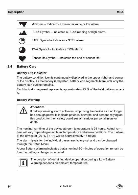
Minimum – Indicates a minimum value or low alarm.
PEAK Symbol – Indicates a PEAK reading or high alarm.
STEL Symbol – Indicates a STEL alarm.
TWA Symbol – Indicates a TWA alarm.
Sensor life Symbol – Indicates the end of sensor life
Attention!
If battery warning alarm activates, stop using the device as it no longer has enough power to indicate potential hazards, and persons relying on this product for their safety could sustain serious personal injury or death.
The duration of remaining device operation during a Low Battery Warning depends on ambient temperatures.
DescriptionMSA
ALTAIR 4XGB 15
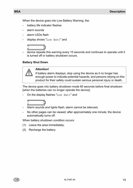
When the device goes into Low Battery Warning, the:
- battery life indicator flashes
- alarm sounds
- alarm LEDs flash
- display shows "Low Batt" and
- device repeats this warning every 15 seconds and continues to operate until it is turned off or battery shutdown occurs.
Battery Shut Down
The device goes into battery shutdown mode 60 seconds before final shutdown [when the batteries can no longer operate the device]:
- On the display flashes "Low Batt" and
- Alarm sounds and lights flash; alarm cannot be silenced,
- No other pages can be viewed; after approximately one minute, the device automatically turns off.
When battery shutdown condition occurs:
(1) Leave the area immediately.
(2) Recharge the battery.
Attention!
If battery alarm displays, stop using the device as it no longer has enough power to indicate potential hazards, and persons relying on this product for their safety could sustain serious personal injury or death.
MSADescription
ALTAIR 4X16 GB
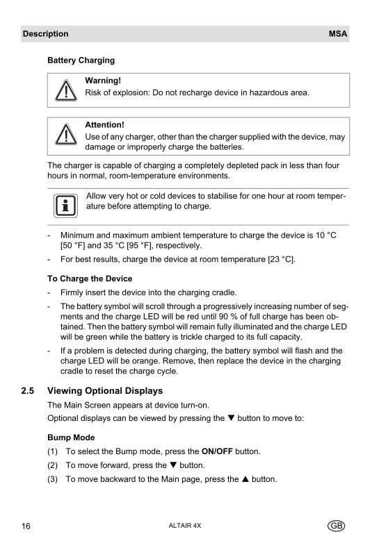
Battery Charging
The charger is capable of charging a completely depleted pack in less than four hours in normal, room-temperature environments.
- Minimum and maximum ambient temperature to charge the device is 10 °C [50 °F] and 35 °C [95 °F], respectively.
- For best results, charge the device at room temperature [23 °C].
To Charge the Device
- Firmly insert the device into the charging cradle.
- The battery symbol will scroll through a progressively increasing number of seg-ments and the charge LED will be red until 90 % of full charge has been ob-tained. Then the battery symbol will remain fully illuminated and the charge LED will be green while the battery is trickle charged to its full capacity.
- If a problem is detected during charging, the battery symbol will flash and the charge LED will be orange. Remove, then replace the device in the charging cradle to reset the charge cycle.
2.5 Viewing Optional Displays
The Main Screen appears at device turn-on.
Optional displays can be viewed by pressing the button to move to:
Bump Mode
(1) To select the Bump mode, press the ON/OFF button.
(2) To move forward, press the button.
(3) To move backward to the Main page, press the button.
Warning!
Risk of explosion: Do not recharge device in hazardous area.
Attention!
Use of any charger, other than the charger supplied with the device, may damage or improperly charge the batteries.
Allow very hot or cold devices to stabilise for one hour at room temper-ature before attempting to charge.
DescriptionMSA
ALTAIR 4XGB 17
Peak Readings [PEAK page]
The peak icon [→ chapter 2.3] shows the highest levels of gas recorded by the de-vice since turn-on or since peak readings were reset.
To reset the peak readings:
(1) Access the PEAK page.
(2) Press the button.
Minimum Readings [MIN page]
This page shows the lowest level of oxygen recorded by the device since turn-on or since the MIN reading was reset.
The minimum icon [→ chapter 2.3] appears on the display.
To reset the MIN reading:
(1) Access the MIN page.
(2) Press the button.
Short Term Exposure Limits [STEL page]
The STEL icon [→ chapter 2.3] appears on the display to show the average expo-sure over a 15 minute period.
When the amount of gas detected by the device is greater than the STEL limit:
- Alarm sounds
- Alarm LEDs flash
- STEL icon flashes.
To reset the STEL:
(1) Access the STEL page.
(2) Press the button.
The STEL alarm is calculated over a 15 minute exposure.
Attention!
If the STEL alarm activates, leave the contaminated area immediately; the ambient gas concentration has reached the preset STEL alarm level. Failure to follow this warning will cause over-exposure to toxic gases and persons relying on this product for their safety could sustain serious per-sonal injury or death.
MSADescription
ALTAIR 4X18 GB
STEL calculation examples:
Assume the device has been running for at least 15 minutes:
15 minute exposure of 35 ppm:
10 minute exposure of 35 ppm and 5 minutes exposure of 5 ppm:
Time Weighted Average [TWA page]
The TWA icon [→ chapter 2.3] appears on the display to show the average expo-sure since the device was turned on or since the TWA reading was reset. When the amount of gas detected is greater than the eight-hour TWA limit:
- Alarm sounds
- Alarm LEDs flash
- TWA icon flashes.
To reset the TWA:
(1) Access the TWA page.
(2) Press the button.
The TWA alarm is calculated over an eight-hour exposure.
[15 minutes x 35 ppm] = 35 ppm
15 minutes
[10 minutes x 35 ppm] + [5 minutes x 5 ppm] = 25 ppm
15 minutes
Attention!
If the TWA alarm activates, leave the contaminated area immediately; the ambient gas concentration has reached the preset TWA alarm level. Failure to follow this warning will cause over-exposure to toxic gases and persons relying on this product for their safety could sustain serious per-sonal injury or death.
DescriptionMSA
ALTAIR 4XGB 19
TWA calculation examples:
1 hour exposure of 50 ppm:
4 hour exposure of 50 ppm and 4 hour exposure of 100 ppm:
12 hour exposure of 100 ppm:
Time Display
Current time appears on the display in a 12 hour format by default.
A 24-hour format can be selected using MSA Link.
Date Display
Current date appears on the display in the format: MMM-DD-YYYY.
Last cal page
Displays the device last successful calibration date in the format: MMM-DD-YYYY
Cal due page
Displays the days until the device's next calibration is due [user selectable].
Motion Alert Activation
To activate or deactivate the Motion Alert feature, press the button while the Motion Alert Activation page is displayed. When the Motion Alert feature is active, the Motion Alert symbol [→ chapter 2.3] will flash every 3 seconds. The device will enter pre-alarm when no motion is detected for 20 seconds. This condition can be cleared by moving the device.
After 30 seconds of inactivity, the full Motion Alert alarm is triggered. This alarm can only be cleared by pressing the button.
[1 hour x 50 ppm] + [7 hours x 0 ppm] = 6.25 ppm
8 hours
[4 hours x 50 ppm] + [4 hours x 100 ppm] = 75 ppm
8 hours
[12 hours x 100 ppm] = 150 ppm
8 hours
MSADescription
ALTAIR 4X20 GB
2.6 Sensor Missing Alarm
The device enters the Sensor Missing alarm if the device detects the sensor is not properly installed in the device or is not functional.
If a sensor is detected as missing, the following occurs:
- "SENSOR ERROR" displays
- The flag above the sensor detected as missing flashes on the display
- Alarm sounds and lights flash.
- Yellow Fault LED is on solid.
- If there is a sensor error at startup, the device shuts off in 60 seconds.
2.7 Sensor End of Life Warning
If a sensor is nearing its end of life, the device will warn the user following a sensor calibration. The sensor is still fully functional at this point, but the warning gives the user time to plan for a replacement sensor and minimise downtime. The ♥ symbol will be continuously displayed. For more details see chapter 3.9.
2.8 Sensor End of Life Indicator
If the device cannot calibrate one or more sensors, the device will display "SPAN ERR" followed by the Alarm symbol and ♥ symbol to indicate end of sensor life. For more details see chapter 3.9.
2.9 Monitoring Toxic Gases
The device can monitor the concentration of the following toxic gases in ambient air:
- Carbon Monoxide [CO]
- Hydrogen Sulphide [H2S]
The device displays the gas concentration in parts per million [PPM] or mg/m3 on the Measuring page until another page is selected or the device is turned off.
Attention!
If an alarm is triggered while using the device, leave the area immediately.
Remaining in the area under such circumstances can cause serious personal injury or death.
DescriptionMSA
ALTAIR 4XGB 21
The device has four gas alarms:
- HIGH Alarm
- LOW Alarm
- STEL Alarm
- TWA Alarm
If the gas concentration reaches or exceeds the alarm set point, the device:
- backlight turns on
- provides a vibrating alarm
- displays and flashes the Alarm symbol and either the Minimum icon [LOW alarm] or the Maximum [PEAK] icon [HIGH alarm]
- enters an alarm state.
2.10 Monitoring Oxygen Concentration
The device monitors the oxygen concentration in ambient air. The alarm set points can be set to activate on two different conditions:
- Enriched - oxygen concentration > 20.8 % or
- Deficient - oxygen concentration < 19.5 %.
When the alarm set point is reached for either of the above conditions:
- an alarm sounds
- alarm LEDs flash
- a vibrating alarm triggers
- device displays and flashes the Alarm icon and either the Minimum icon [En-riched alarm] or the Maximum icon [Deficient alarm] [→ chapter 2.3] along with the corresponding oxygen concentration.
While the device can detect up to 30 % oxygen in ambient air, it is approved for use only up to 21 % oxygen.
Attention!
If an alarm is triggered while using the device, leave the area immediately.
Remaining in the area under such circumstances can cause serious personal injury or death.

MSADescription
ALTAIR 4X22 GB
2.11 Monitoring Combustible Gases
The device can monitor these concentrations in ambient air:
- Methane
- Combustible gases
The device displays the gas concentration in % LEL or % CH4 on the Measuring page until another page is selected or the device is turned off.
The device has two alarm set points:
- HIGH Alarm
- LOW Alarm
If the gas concentration reaches or exceeds the alarm set point, the device:
- backlight turns on
- a vibrating alarm triggers
- displays and flashes the Alarm symbol and either the Minimum icon [LOW alarm] or the Maximum [PEAK] icon [HIGH alarm]
- enters an alarm state.
The LOW alarm [oxygen deficient] is latching and will not automatically reset when the O2 concentration rises above the LOW set point. To re-set the alarm press the button. If the alarm condition still exists, the button only silences the alarm for five seconds.
False oxygen alarms can occur due to changes in barometric pressure [altitude] or extreme changes in ambient temperature.
It is recommended that an oxygen calibration be performed at the tem-perature and pressure of use. Be sure that the device is in known fresh air before performing a calibration.
Attention!
If an alarm is triggered while using the device, leave the area immediately.
Remaining in the area under such circumstances can cause serious personal injury or death.
OperationMSA
ALTAIR 4XGB 23
In such cases, the device LockAlarm feature activates.
3 Operation
3.1 Environmental Factors
A number of environmental factors may affect the gas sensor readings, including changes in pressure, humidity and temperature. Pressure and humidity changes af-fect the amount of oxygen actually present in the atmosphere.
Pressure Changes
If pressure changes rapidly [e.g., stepping through airlock], the oxygen sensor read-ing may temporarily shift and possibly cause the detector to alarm. While the per-centage of oxygen may remain at or near 20.8 Vol %, the total amount of oxygen present in the atmosphere available for respiration may become a hazard if the overall pressure is reduced by a significant degree.
Humidity Changes
If humidity changes by any significant degree [e.g., going from a dry, air conditioned environment to outdoor, moisture laden air], oxygen readings can be reduced by up to 0.5 %, due to water vapour in the air displacing oxygen.
The oxygen sensor has a special filter to reduce the effects of humidity changes on oxygen readings. This effect will not be noticed immediately, but slowly impacts oxygen readings over several hours.
When gas reading exceeds 100% LEL CH4, the device enters a Lock Alarm state , the combustible sensor shuts down and displays “xxx” in place of the actual reading. This state can only be reset by turn-ing the device off and on in a fresh air environment.
Attention!
A combustible gas reading of "100” indicates the atmosphere is above 100% LEL CH4 and an explosion hazard exists. Move away from con-taminated area immediately.
Check your national standard values for 100 % LEL. Some countries use 5 Vol % and some use 4.4 Vol % as 100 % LEL CH4.
MSAOperation
ALTAIR 4X24 GB
Temperature Changes
The sensors have built-in temperature compensation. However, if temperature shifts dramatically, the sensor reading may shift. Zero the device at the work site temperature for the least effect.
3.2 Turning on the Device
For more information, see the flow charts in [→ chapter 7].
Turn the device on with the ON/OFF button.
The device performs a self test and then goes to Fresh Air Setup:
- all display segments are activated
- audible alarm sounds
- alarm LEDs light
- vibrating alarm is activated.
During the self test, the device checks for missing sensors. In the case of a missing sensor, the device displays the Sensor Missing screen and alarms until it is turned off. Otherwise, the turn-on sequence continues.
The device displays:
- Alarm & display self test
- Manufacturer name
- Device name
- Software version
- Sensor discovery
- Combustible gas type
- Toxic gas units
- Alarm set points [PEAK, MIN] [STEL, TWA]
- Calibration values
- Date and time display
- Last cal date [if activated]
- CAL due date [if activated]
- Fresh Air Setup option.
OperationMSA
ALTAIR 4XGB 25
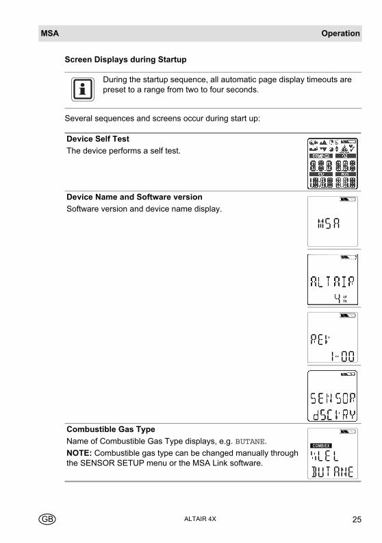
Screen Displays during Startup
Several sequences and screens occur during start up:
During the startup sequence, all automatic page display timeouts are preset to a range from two to four seconds.
Device Self Test
The device performs a self test.
Device Name and Software version
Software version and device name display.
Combustible Gas Type
Name of Combustible Gas Type displays, e.g. BUTANE.
NOTE: Combustible gas type can be changed manually through the SENSOR SETUP menu or the MSA Link software.
COMB/EX
MSAOperation
ALTAIR 4X26 GB
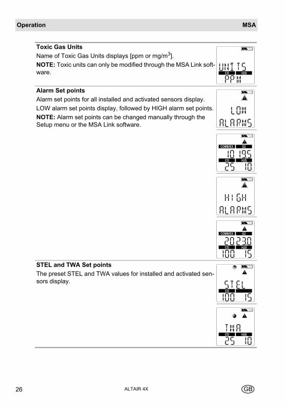
Toxic Gas Units
Name of Toxic Gas Units displays [ppm or mg/m3].
NOTE: Toxic units can only be modified through the MSA Link soft-ware.
Alarm Set points
Alarm set points for all installed and activated sensors display.
LOW alarm set points display, followed by HIGH alarm set points.
NOTE: Alarm set points can be changed manually through the Setup menu or the MSA Link software.
STEL and TWA Set points
The preset STEL and TWA values for installed and activated sen-sors display.
H2SCO
COMB/EX O2
H2SCO
COMB/EX O2
H2SCO
CO
H2SCO
OperationMSA
ALTAIR 4XGB 27
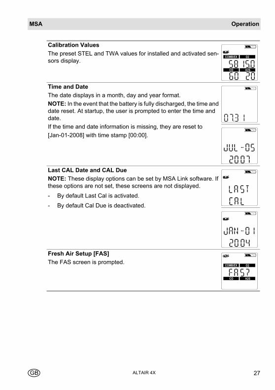
Calibration Values
The preset STEL and TWA values for installed and activated sen-sors display.
Time and Date
The date displays in a month, day and year format.
NOTE: In the event that the battery is fully discharged, the time and date reset. At startup, the user is prompted to enter the time and date.
If the time and date information is missing, they are reset to
[Jan-01-2008] with time stamp [00:00].
Last CAL Date and CAL Due
NOTE: These display options can be set by MSA Link software. If these options are not set, these screens are not displayed.
- By default Last Cal is activated.
- By default Cal Due is deactivated.
Fresh Air Setup [FAS]
The FAS screen is prompted.
COMB/EX O2
H2SCO
COMB/EX O2
H2SCO
MSAOperation
ALTAIR 4X28 GB
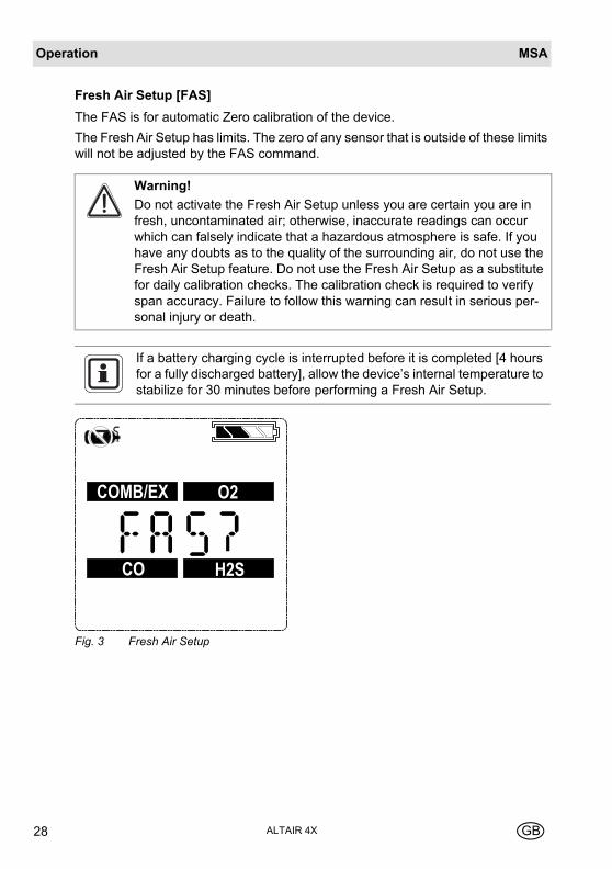
Fresh Air Setup [FAS]
The FAS is for automatic Zero calibration of the device.
The Fresh Air Setup has limits. The zero of any sensor that is outside of these limits will not be adjusted by the FAS command.
Fig. 3 Fresh Air Setup
Warning!
Do not activate the Fresh Air Setup unless you are certain you are in fresh, uncontaminated air; otherwise, inaccurate readings can occur which can falsely indicate that a hazardous atmosphere is safe. If you have any doubts as to the quality of the surrounding air, do not use the Fresh Air Setup feature. Do not use the Fresh Air Setup as a substitute for daily calibration checks. The calibration check is required to verify span accuracy. Failure to follow this warning can result in serious per-sonal injury or death.
If a battery charging cycle is interrupted before it is completed [4 hours for a fully discharged battery], allow the device’s internal temperature to stabilize for 30 minutes before performing a Fresh Air Setup.
COMB/EX O2
H2SCO
OperationMSA
ALTAIR 4XGB 29
If this option is enabled, the device displays "FAS?", prompting the user to perform a Fresh Air Setup.
(3) Press the button to bypass the Fresh Air Setup.
The Fresh Air Setup is skipped and the device goes to the Measuring page [Main page].
(4) Press the ON/OFF button within 10 seconds to perform the Fresh Air Setup.
The device starts the FAS.
The screen shows a No Gas Symbol, a blinking hourglass, and all enabled gas sensor readings.
At the end of the FAS Calibration, the device displays "FAS OK" or "FAS ERR". along with the flags of the sensors that were outside of the FAS limits. All sensors that are within the FAS limits will be zeroed.
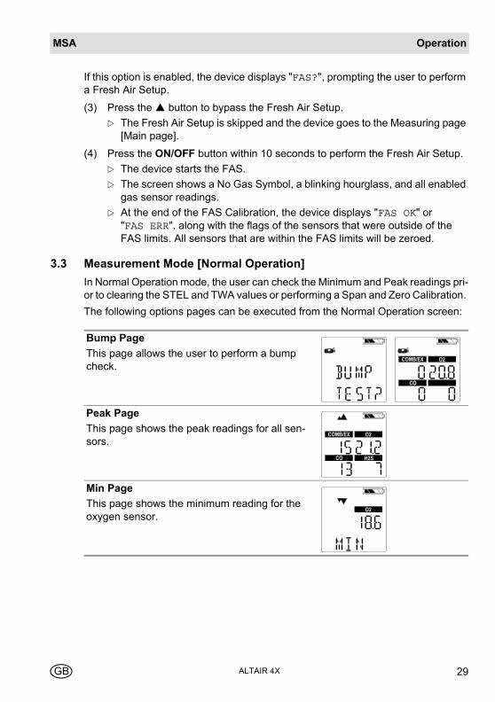
3.3 Measurement Mode [Normal Operation]
In Normal Operation mode, the user can check the Minimum and Peak readings pri-or to clearing the STEL and TWA values or performing a Span and Zero Calibration.
The following options pages can be executed from the Normal Operation screen:
Bump Page
This page allows the user to perform a bump check.
Peak Page
This page shows the peak readings for all sen-sors.
Min Page
This page shows the minimum reading for the oxygen sensor.
COMB/EX O2
CO
COMB/EX O2
H2SCO
O2
MSAOperation
ALTAIR 4X30 GB
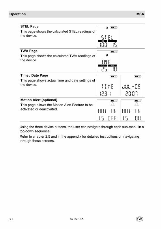
Using the three device buttons, the user can navigate through each sub-menu in a top/down sequence.
Refer to chapter 2.5 and in the appendix for detailed instructions on navigating through these screens.
STEL Page
This page shows the calculated STEL readings of the device.
TWA Page
This page shows the calculated TWA readings of the device.
Time / Date Page
This page shows actual time and date settings of the device.
Motion Alert [optional]
This page allows the Motion Alert Feature to be activated or deactivated.
CO
H2SCO
OperationMSA
ALTAIR 4XGB 31
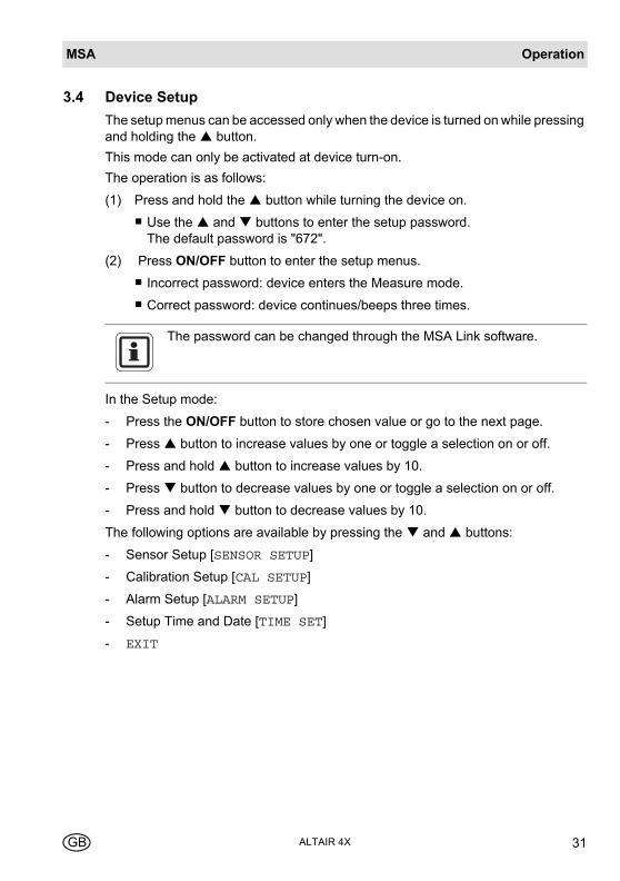
3.4 Device Setup
The setup menus can be accessed only when the device is turned on while pressing and holding the button.
This mode can only be activated at device turn-on.
The operation is as follows:
(1) Press and hold the button while turning the device on.
Use the and buttons to enter the setup password.The default password is "672".
(2) Press ON/OFF button to enter the setup menus.
Incorrect password: device enters the Measure mode.
Correct password: device continues/beeps three times.
In the Setup mode:
- Press the ON/OFF button to store chosen value or go to the next page.
- Press button to increase values by one or toggle a selection on or off.
- Press and hold button to increase values by 10.
- Press button to decrease values by one or toggle a selection on or off.
- Press and hold button to decrease values by 10.
The following options are available by pressing the and buttons:
- Sensor Setup [SENSOR SETUP]
- Calibration Setup [CAL SETUP]
- Alarm Setup [ALARM SETUP]
- Setup Time and Date [TIME SET]
- EXIT
The password can be changed through the MSA Link software.
MSAOperation
ALTAIR 4X32 GB
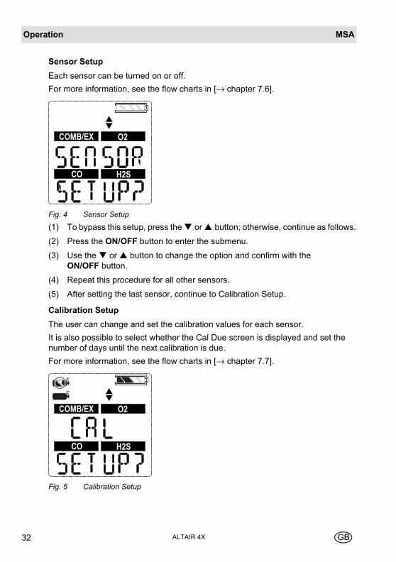
Sensor Setup
Each sensor can be turned on or off.
For more information, see the flow charts in [→ chapter 7.6].
Fig. 4 Sensor Setup
(1) To bypass this setup, press the or button; otherwise, continue as follows.
(2) Press the ON/OFF button to enter the submenu.
(3) Use the or button to change the option and confirm with the ON/OFF button.
(4) Repeat this procedure for all other sensors.
(5) After setting the last sensor, continue to Calibration Setup.
Calibration Setup
The user can change and set the calibration values for each sensor.
It is also possible to select whether the Cal Due screen is displayed and set the number of days until the next calibration is due.
For more information, see the flow charts in [→ chapter 7.7].
Fig. 5 Calibration Setup
COMB/EX O2
H2SCO
COMB/EX O2
H2SCO
OperationMSA
ALTAIR 4XGB 33
(1) To bypass this setup, press the or button; otherwise, continue as follows.
(2) Press the ON/OFF button to enter the submenu.
The calibration gas concentration of the first sensor is shown.
(3) Press the or button to change the value.
(4) Press the ON/OFF button to store the value.
Setup screen for the next sensor is displayed.
(5) Repeat the procedure for all other sensors.
After setting the last sensor, the user is prompted to set CALDUE.
(6) Press the or button to enable or disable CALDUE.
Press the ON/OFF button to confirm the selection.
(7) If CALDUE is set on, press the or button to select the number of days
(8) Confirm with the ON/OFF button.
(9) After confirmation, continue to Alarm setup.
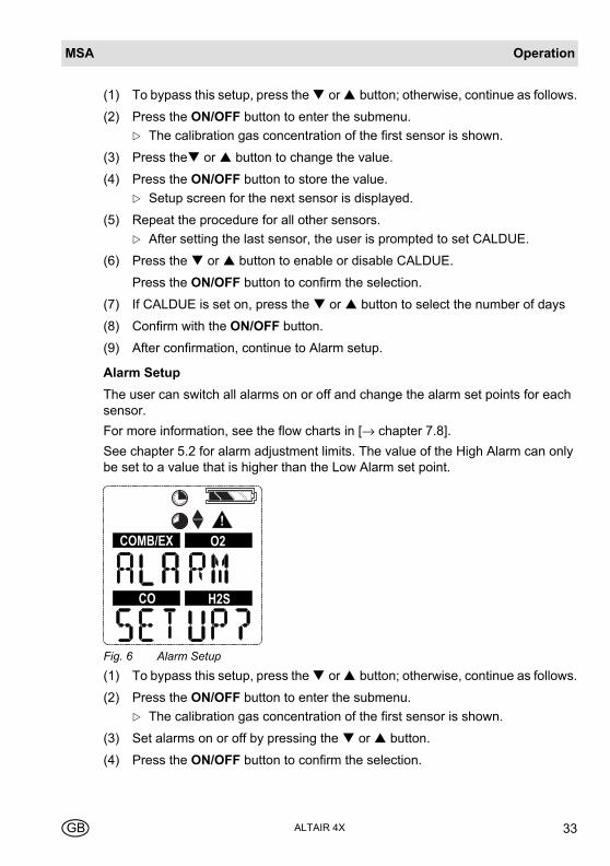
Alarm Setup
The user can switch all alarms on or off and change the alarm set points for each sensor.
For more information, see the flow charts in [→ chapter 7.8].
See chapter 5.2 for alarm adjustment limits. The value of the High Alarm can only be set to a value that is higher than the Low Alarm set point.
Fig. 6 Alarm Setup
(1) To bypass this setup, press the or button; otherwise, continue as follows.
(2) Press the ON/OFF button to enter the submenu.
The calibration gas concentration of the first sensor is shown.
(3) Set alarms on or off by pressing the or button.
(4) Press the ON/OFF button to confirm the selection.
COMB/EX O2
H2SCO
MSAOperation
ALTAIR 4X34 GB
LOW ALARM settings for the first sensor display.
(5) Press the or button to change the value.
(6) Press the ON/OFF button to store the value.
HIGH ALARM settings for the first sensor display.
(7) Press the or button to change the value.
(8) Press the ON/OFF button to store the value.
STEL ALARM settings [for toxic sensors only] display.
(9) Press the or button to change the value.
(10) Press the ON/OFF button to store the value.
TWA ALARM settings [for toxic sensor only] for display.
(11) Press the or button to change the value.
(12) Press the ON/OFF button to store the value.
(13) Repeat the procedure for all other sensors.
(14) After setting the last sensor, continue to Time and Date setup.
60% L.E.L. or 3.0% volume of methane is the maximum High Alarm set point that can be programmed.
The combustible alarm can be turned off in the device setup.
When the combustible alarm is turned off, this is only indicated during startup of the device: a startup screen will indicate that the combustible alarm is turned off. When turned on, the combustible high alarm is latching.
The combustible alarm can be silenced momentarily by pressing the button. However, if the gas concentration causing the alarm is still present, the device will go back into alarm.
OperationMSA
ALTAIR 4XGB 35
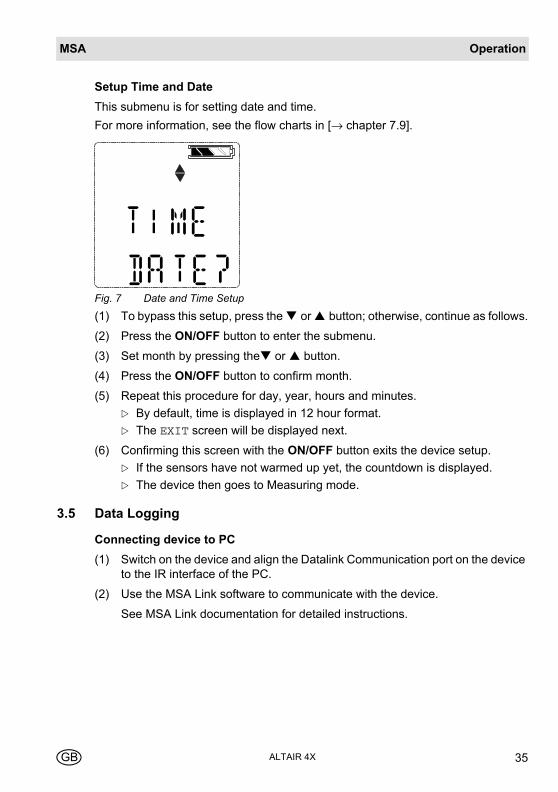
Setup Time and Date
This submenu is for setting date and time.
For more information, see the flow charts in [→ chapter 7.9].
Fig. 7 Date and Time Setup
(1) To bypass this setup, press the or button; otherwise, continue as follows.
(2) Press the ON/OFF button to enter the submenu.
(3) Set month by pressing the or button.
(4) Press the ON/OFF button to confirm month.
(5) Repeat this procedure for day, year, hours and minutes.
By default, time is displayed in 12 hour format.
The EXIT screen will be displayed next.
(6) Confirming this screen with the ON/OFF button exits the device setup.
If the sensors have not warmed up yet, the countdown is displayed.
The device then goes to Measuring mode.
3.5 Data Logging
Connecting device to PC
(1) Switch on the device and align the Datalink Communication port on the device to the IR interface of the PC.
(2) Use the MSA Link software to communicate with the device.
See MSA Link documentation for detailed instructions.
MSAOperation
ALTAIR 4X36 GB
3.6 Function Tests
Alarm Test
Turn on the device. Verify that:
- all LCD segments are activated momentarily
- alarm LEDs flash
- horn sounds briefly
- vibrating alarm triggers briefly.
3.7 Safe LED
The device is equipped with a green Safe LED. This green Safe LED flashes every 15 seconds under the following conditions:
- the SAFE LED feature is enabled
- device is in Measurement Mode [Normal Operation]
- combustible reading is 0% LEL or 0.00% CH4
- Oxygen [O2] reading is 20.8%
- Carbon Monoxide [CO] reading is 0 ppm or mg/m3
- Hydrogen Sulphide [H2S] reading is 0 ppm or 0 mg/m3
- no gas alarms are present [low or high]
- device is not in Low Battery warning or alarm
- CO, H2S, STEL and TWA readings are 0 ppm or 0 mg/m³.
3.8 Bump Test
This test quickly confirms that the gas sensors are functioning. Perform a full cali-bration periodically to ensure accuracy and immediately if the device fails the Bump Test. The Bump Test can be performed using the procedure below or auto-matically using the GALAXY Test Stand.
It is required that the device's sensitivity be tested before each day's use on a known concentration of methane equivalent to 25 - 50% of full scale concentration. Accuracy must be within 0 to +20% of actual. Correct accuracy by performing the calibration procedure within this manual.
Attention!
Perform a Bump Test before each day’s use to verify proper device operation. Failure to perform this test can result in serious personal inju-ry or death.
OperationMSA
ALTAIR 4XGB 37
Equipment
See accessory section for ordering information for these components.
- Calibration Check Gas Cylinder
- 0.25 liters/min. Flow Regulator
- 1/8” ID Superthane Ester Tubing
- Calibration Cap
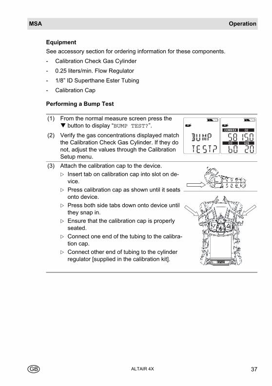
Performing a Bump Test
(1) From the normal measure screen press the button to display “BUMP TEST?”.
(2) Verify the gas concentrations displayed match the Calibration Check Gas Cylinder. If they do not, adjust the values through the Calibration Setup menu.
(3) Attach the calibration cap to the device.
Insert tab on calibration cap into slot on de-vice.
Press calibration cap as shown until it seats onto device.
Press both side tabs down onto device until they snap in.
Ensure that the calibration cap is properly seated.
Connect one end of the tubing to the calibra-tion cap.
Connect other end of tubing to the cylinder regulator [supplied in the calibration kit].
COMB/EX O2
H2SCO
MSAOperation
ALTAIR 4X38 GB
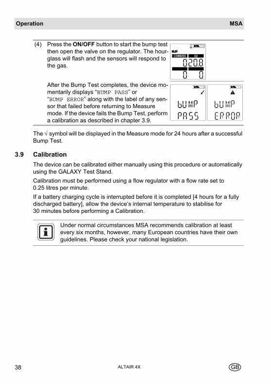
The √ symbol will be displayed in the Measure mode for 24 hours after a successful Bump Test.
3.9 Calibration
The device can be calibrated either manually using this procedure or automatically using the GALAXY Test Stand.
Calibration must be performed using a flow regulator with a flow rate set to 0.25 litres per minute.
If a battery charging cycle is interrupted before it is completed [4 hours for a fully discharged battery], allow the device’s internal temperature to stabilise for 30 minutes before performing a Calibration.
(4) Press the ON/OFF button to start the bump test then open the valve on the regulator. The hour-glass will flash and the sensors will respond to the gas.
After the Bump Test completes, the device mo-mentarily displays “BUMP PASS” or “BUMP ERROR” along with the label of any sen-sor that failed before returning to Measure mode. If the device fails the Bump Test, perform a calibration as described in chapter 3.9.
COMB/EX O2
Under normal circumstances MSA recommends calibration at least every six months, however, many European countries have their own guidelines. Please check your national legislation.
OperationMSA
ALTAIR 4XGB 39
Fresh Air Setup and Zero Calibration
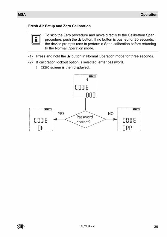
(1) Press and hold the button in Normal Operation mode for three seconds.
(2) If calibration lockout option is selected, enter password.
ZERO screen is then displayed.
To skip the Zero procedure and move directly to the Calibration Span procedure, push the button. If no button is pushed for 30 seconds, the device prompts user to perform a Span calibration before returning to the Normal Operation mode.
Password correct?
YES NO
MSAOperation
ALTAIR 4X40 GB
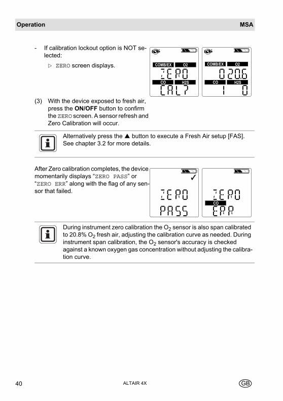
- If calibration lockout option is NOT se-lected:
ZERO screen displays.
(3) With the device exposed to fresh air, press the ON/OFF button to confirm the ZERO screen. A sensor refresh and Zero Calibration will occur.
COMB/EX O2
H2SCO
COMB/EX O2
H2SCO
Alternatively press the button to execute a Fresh Air setup [FAS]. See chapter 3.2 for more details.
After Zero calibration completes, the device momentarily displays “ZERO PASS” or “ZERO ERR” along with the flag of any sen-sor that failed.
CO
During instrument zero calibration the O2 sensor is also span calibrated to 20.8% O2 fresh air, adjusting the calibration curve as needed. During instrument span calibration, the O2 sensor's accuracy is checked against a known oxygen gas concentration without adjusting the calibra-tion curve.
OperationMSA
ALTAIR 4XGB 41
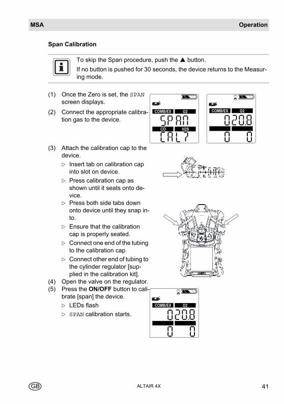
Span Calibration
To skip the Span procedure, push the button.
If no button is pushed for 30 seconds, the device returns to the Measur-ing mode.
(1) Once the Zero is set, the SPAN screen displays.
(2) Connect the appropriate calibra-tion gas to the device.
(3) Attach the calibration cap to the device.
Insert tab on calibration cap into slot on device.
Press calibration cap as shown until it seats onto de-vice.
Press both side tabs down onto device until they snap in-to.
Ensure that the calibration cap is properly seated.
Connect one end of the tubing to the calibration cap.
Connect other end of tubing to the cylinder regulator [sup-plied in the calibration kit].
(4) Open the valve on the regulator.(5) Press the ON/OFF button to cali-
brate [span] the device.
LEDs flash
SPAN calibration starts.
H2SCO
COMB/EX O2 COMB/EX O2
COMB/EX O2
MSAOperation
ALTAIR 4X42 GB
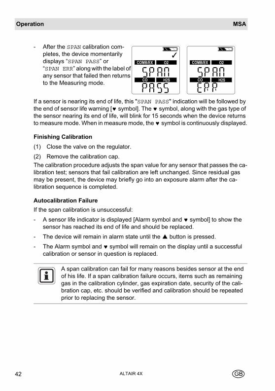
If a sensor is nearing its end of life, this "SPAN PASS" indication will be followed by the end of sensor life warning [♥ symbol]. The ♥ symbol, along with the gas type of the sensor nearing its end of life, will blink for 15 seconds when the device returns to measure mode. When in measure mode, the ♥ symbol is continuously displayed.
Finishing Calibration
(1) Close the valve on the regulator.
(2) Remove the calibration cap.
The calibration procedure adjusts the span value for any sensor that passes the ca-libration test; sensors that fail calibration are left unchanged. Since residual gas may be present, the device may briefly go into an exposure alarm after the ca-libration sequence is completed.
Autocalibration Failure
If the span calibration is unsuccessful:
- A sensor life indicator is displayed [Alarm symbol and ♥ symbol] to show the sensor has reached its end of life and should be replaced.
- The device will remain in alarm state until the button is pressed.
- The Alarm symbol and ♥ symbol will remain on the display until a successful calibration or sensor in question is replaced.
- After the SPAN calibration com-pletes, the device momentarily displays “SPAN PASS” or “SPAN ERR” along with the label of any sensor that failed then returns to the Measuring mode.
COMB/EX O2
H2SCO
COMB/EX O2
H2SCO
A span calibration can fail for many reasons besides sensor at the end of his life. If a span calibration failure occurs, items such as remaining gas in the calibration cylinder, gas expiration date, security of the cali-bration cap, etc. should be verified and calibration should be repeated prior to replacing the sensor.
MaintenanceMSA
ALTAIR 4XGB 43
4 MaintenanceIf an error occurs during operation, use the displayed error codes to determine ap-propriate next steps.
The MSA warranty for sensors, rechargeable batteries, housing and electronics is only valid if the device is annually maintained by the manufacturer or an authorized person in accordance with the operating manual.
Refer to EN 50073 [Guide for the selection, installation, use and main-tenance of apparatus for the detection and measurement of combusti-ble gases or oxygen].

MSAMaintenance
ALTAIR 4X44 GB
4.1 Troubleshooting
Problem Description Reaction
ERROR TEMP Temperature is below
-40°C or above 75°C.
Return device to normal temperature range and recali-brate.
Contact MSA
ERROR EE EEPROM Memory error Contact MSA
ERROR PRG Flash Memory error Contact MSA
ERROR RAM RAM Memory error Contact MSA
ERROR UNK Unknown error Contact MSA
LOW BATT
Battery warning repeats every 15 seconds.
Remove from service as soon as possible and recharge battery
BATT ALARM
Battery is completely discharged.
Device is no longer sensing gas.
Remove from service and recharge battery.
ERROR CHARGE Charge error Device must be between 10° C and 36° C to charge.
Contact MSA if problem persists
SENSOR ERROR Missing Sensor Verify if sensor is properly installed
Device does not turn on
Low battery Charge device
Sensor warning Sensor is near the end of its life
Sensor alarm Sensor has reached the end of its life and cannot be calibrated. Re-place sensor and recalibrate.
&
MaintenanceMSA
ALTAIR 4XGB 45
4.2 Live Maintenance Procedure - Replacing and Adding a Sensor
To add a sensor to an device that is not already equipped with a full array of sen-sors, remove the sensor plug from in front of the formerly unused sensor housing.
(1) Verify that the device is turned off.
(2) Remove the four case screws, and remove the case front while carefully not-ing the orientation of the sensor gasket.
(3) Gently lift out and properly discard the sensor to be replaced.
Using fingers only, gently remove the toxic, combustible, or oxygen sensor by gently rocking it while pulling it straight from its socket.
(4) Carefully align the new sensor contact pins with the sockets on the printed cir-cuit board and pressing it firmly in place.
Insert the toxic sensor by placing it in the left-hand position of the sensor holder.
Insert the O2 sensor by placing it in the right-hand position of the sensor holder.
Insert the combustible sensor by placing it in the middle position of the sen-sor holder.
(5) Ensure groove in combustible sensor aligns with tab at top of holder.
If any sensor is not to be installed, ensure that a sensor plug is installed properly in its place.
Warning!
Remove and reinstall sensors carefully, ensuring that the components are not damaged; otherwise device intrinsic safety may be adversely af-fected, wrong readings could occur, and persons relying on this product for their safety could sustain serious personal injury or death.
Attention!
Before handling the PC board, ensure you are properly grounded; oth-erwise, static charges from your body could damage the electronics. Such damage is not covered by the warranty. Grounding straps and kits are available from electronics suppliers.
While device case is open, do not touch any internal components with metallic/conductive objects or tools.
Damage to the device can occur.

MSAMaintenance
ALTAIR 4X46 GB
(6) If replacing sensor filters at this time:
Carefully peel off old filters taking care not to damage the inside of the case.
On new filters peel off backing exposing adhesive. Note proper orientation of each filter and apply to inside of front case adhesive side against case.
Press filter into place taking care not to damage filter surface.
(7) Reinstall the sensor gasket in the case front.
(8) Ensure sensor gasket is properly installed.
(9) Re-install the screws.
(10) Turn on the device.
(11) Calibrate the device after the sensors have stabilised.
If the sensor replaced is the same as the previous sensor:
If the sensor replaced is not the same as the previous sensor or this sensor channel was deactivated:
- The device starts up normally.
- The device automatically senses that a new sensor is installed and displays the "SENSOR DSCVRY" screen.
- The device automatically senses the difference and displays "SENSOR CHANGE".
- "ACCEPT?" appears on the display.
Accept the change with button or reject with button.
Go into the sensor setup and turn on the appropriate sensor [→ chapter 3.4].
Danger!
Calibration is required after a sensor is installed; otherwise, the device will not perform as expected and persons relying on this product for their safety could sustain serious personal injury or death.
Allow sensors to stabilise at room temperature for at least 30 minutes before calibration [→ chapter 3.9].
MaintenanceMSA
ALTAIR 4XGB 47
4.3 Cleaning
Clean the exterior of the device regularly using only a damp cloth. Do not use clea-ning agents as many contain silicones which will damage the combustible sensor.
4.4 Storage
When not in use, store the device in a safe, dry place between 18 °C and 30 °C [65 °F and 86 °F]. After storage, always recheck device calibration before use.
4.5 Scope of Delivery
Pack the device in its original shipping container with suitable padding. If the origi-nal container is unavailable, an equivalent container may be substituted.
MSATechnical Specifications/Certifications
ALTAIR 4X48 GB
5 Technical Specifications/Certifications
5.1 Technical Specifications
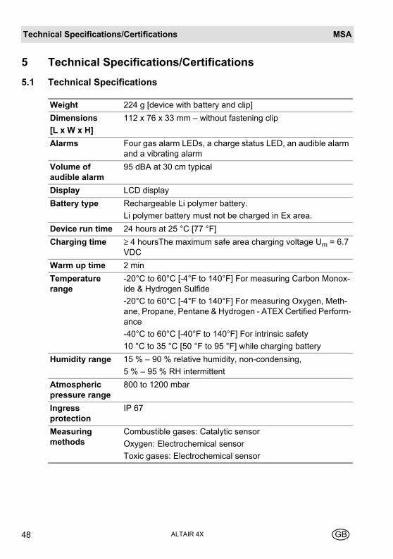
Weight 224 g [device with battery and clip]
Dimensions
[L x W x H]
112 x 76 x 33 mm – without fastening clip
Alarms Four gas alarm LEDs, a charge status LED, an audible alarm and a vibrating alarm
Volume of audible alarm
95 dBA at 30 cm typical
Display LCD display
Battery type Rechargeable Li polymer battery.
Li polymer battery must not be charged in Ex area.
Device run time 24 hours at 25 °C [77 °F]
Charging time ≥ 4 hoursThe maximum safe area charging voltage Um = 6.7 VDC
Warm up time 2 min
Temperature range
-20°C to 60°C [-4°F to 140°F] For measuring Carbon Monox-ide & Hydrogen Sulfide
-20°C to 60°C [-4°F to 140°F] For measuring Oxygen, Meth-ane, Propane, Pentane & Hydrogen - ATEX Certified Perform-ance
-40°C to 60°C [-40°F to 140°F] For intrinsic safety
10 °C to 35 °C [50 °F to 95 °F] while charging battery
Humidity range 15 % – 90 % relative humidity, non-condensing,
5 % – 95 % RH intermittent
Atmospheric pressure range
800 to 1200 mbar
Ingress protection
IP 67
Measuring methods
Combustible gases: Catalytic sensor
Oxygen: Electrochemical sensor
Toxic gases: Electrochemical sensor
Technical Specifications/CertificationsMSA
ALTAIR 4XGB 49
5.2 Factory-set Alarm thresholds
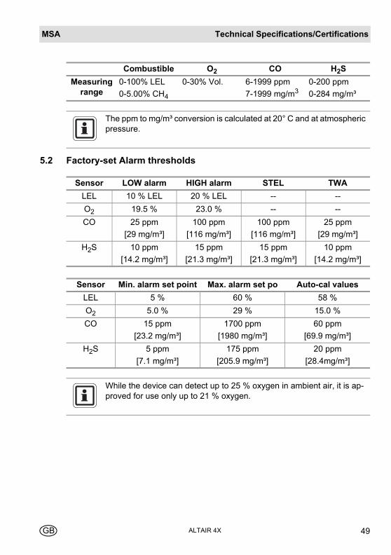
Combustible O2 CO H2S
Measuring range
0-100% LEL
0-5.00% CH4
0-30% Vol. 6-1999 ppm
7-1999 mg/m30-200 ppm
0-284 mg/m³
The ppm to mg/m³ conversion is calculated at 20° C and at atmospheric pressure.
Sensor LOW alarm HIGH alarm STEL TWA
LEL 10 % LEL 20 % LEL -- --
O2 19.5 % 23.0 % -- --
CO 25 ppm
[29 mg/m³]
100 ppm
[116 mg/m³]
100 ppm
[116 mg/m³]
25 ppm
[29 mg/m³]
H2S 10 ppm
[14.2 mg/m³]
15 ppm
[21.3 mg/m³]
15 ppm
[21.3 mg/m³]
10 ppm
[14.2 mg/m³]
Sensor Min. alarm set point Max. alarm set po Auto-cal values
LEL 5 % 60 % 58 %
O2 5.0 % 29 % 15.0 %
CO 15 ppm
[23.2 mg/m³]
1700 ppm
[1980 mg/m³]
60 ppm
[69.9 mg/m³]
H2S 5 ppm
[7.1 mg/m³]
175 ppm
[205.9 mg/m³]
20 ppm
[28.4mg/m³]
While the device can detect up to 25 % oxygen in ambient air, it is ap-proved for use only up to 21 % oxygen.
MSATechnical Specifications/Certifications
ALTAIR 4X50 GB
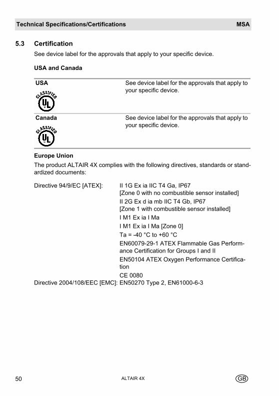
5.3 Certification
See device label for the approvals that apply to your specific device.
USA and Canada
Europe Union
The product ALTAIR 4X complies with the following directives, standards or stand-ardized documents:
USA See device label for the approvals that apply to your specific device.
Canada See device label for the approvals that apply to your specific device.
Directive 94/9/EC [ATEX]: II 1G Ex ia IIC T4 Ga, IP67 [Zone 0 with no combustible sensor installed]
II 2G Ex d ia mb IIC T4 Gb, IP67 [Zone 1 with combustible sensor installed]
I M1 Ex ia I Ma
I M1 Ex ia I Ma [Zone 0]
Ta = -40 °C to +60 °C
EN60079-29-1 ATEX Flammable Gas Perform-ance Certification for Groups I and II
EN50104 ATEX Oxygen Performance Certifica-tion
CE 0080Directive 2004/108/EEC [EMC]: EN50270 Type 2, EN61000-6-3
Technical Specifications/CertificationsMSA
ALTAIR 4XGB 51
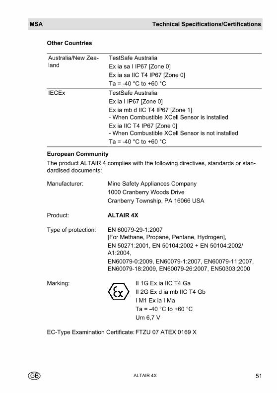
Other Countries
European Community
The product ALTAIR 4 complies with the following directives, standards or stan-dardised documents:
Australia/New Zea-land
TestSafe Australia
Ex ia sa I IP67 [Zone 0]
Ex ia sa IIC T4 IP67 [Zone 0]
Ta = -40 °C to +60 °C
IECEx TestSafe Australia
Ex ia I IP67 [Zone 0]
Ex ia mb d IIC T4 IP67 [Zone 1] - When Combustible XCell Sensor is installed
Ex ia IIC T4 IP67 [Zone 0] - When Combustible XCell Sensor is not installed
Ta = -40 °C to +60 °C
Manufacturer: Mine Safety Appliances Company
1000 Cranberry Woods Drive
Cranberry Township, PA 16066 USA
Product: ALTAIR 4X
Type of protection: EN 60079-29-1:2007 [For Methane, Propane, Pentane, Hydrogen],
EN 50271:2001, EN 50104:2002 + EN 50104:2002/A1:2004,
EN60079-0:2009, EN60079-1:2007, EN60079-11:2007, EN60079-18:2009, EN60079-26:2007, EN50303:2000
Marking: II 1G Ex ia IIC T4 Ga
II 2G Ex d ia mb IIC T4 Gb
I M1 Ex ia I Ma
Ta = -40 °C to +60 °C
Um 6,7 V
EC-Type Examination Certificate: FTZU 07 ATEX 0169 X
MSATechnical Specifications/Certifications
ALTAIR 4X52 GB
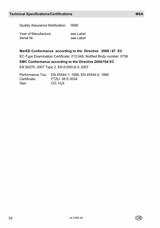
MarED Conformance according to the Directive 2008 / 67 EC
EC-Type Examination Certificate: 213.048, Notified Body number: 0736
EMC Conformance according to the Directive 2004/104 EC
EN 50270: 2007 Type 2, EN 61000-6-3: 2007
Quality Assurance Notification: 0080
Year of Manufacture: see LabelSerial Nr.: see Label
Performance Tox: EN 45544-1: 1999, EN 45544-2: 1999Certificate: FTZU 08 E 0034Gas: CO, H2S
Technical Specifications/CertificationsMSA
ALTAIR 4XGB 53
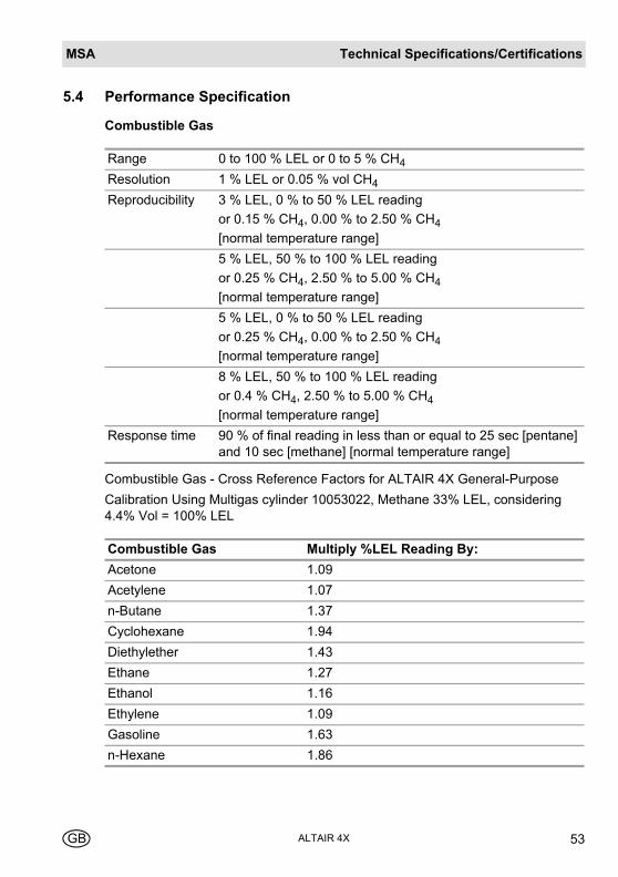
5.4 Performance Specification
Combustible Gas
Combustible Gas - Cross Reference Factors for ALTAIR 4X General-Purpose
Calibration Using Multigas cylinder 10053022, Methane 33% LEL, considering 4.4% Vol = 100% LEL
Range 0 to 100 % LEL or 0 to 5 % CH4
Resolution 1 % LEL or 0.05 % vol CH4
Reproducibility 3 % LEL, 0 % to 50 % LEL reading
or 0.15 % CH4, 0.00 % to 2.50 % CH4
[normal temperature range]
5 % LEL, 50 % to 100 % LEL reading
or 0.25 % CH4, 2.50 % to 5.00 % CH4
[normal temperature range]
5 % LEL, 0 % to 50 % LEL reading
or 0.25 % CH4, 0.00 % to 2.50 % CH4
[normal temperature range]
8 % LEL, 50 % to 100 % LEL reading
or 0.4 % CH4, 2.50 % to 5.00 % CH4
[normal temperature range]
Response time 90 % of final reading in less than or equal to 25 sec [pentane] and 10 sec [methane] [normal temperature range]
Combustible Gas Multiply %LEL Reading By:
Acetone 1.09
Acetylene 1.07
n-Butane 1.37
Cyclohexane 1.94
Diethylether 1.43
Ethane 1.27
Ethanol 1.16
Ethylene 1.09
Gasoline 1.63
n-Hexane 1.86
MSATechnical Specifications/Certifications
ALTAIR 4X54 GB
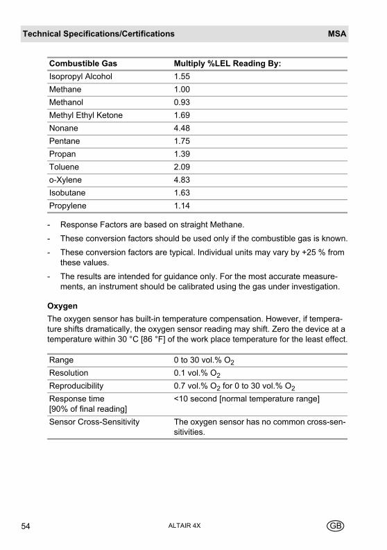
- Response Factors are based on straight Methane.
- These conversion factors should be used only if the combustible gas is known.
- These conversion factors are typical. Individual units may vary by +25 % from these values.
- The results are intended for guidance only. For the most accurate measure-ments, an instrument should be calibrated using the gas under investigation.
Oxygen
The oxygen sensor has built-in temperature compensation. However, if tempera-ture shifts dramatically, the oxygen sensor reading may shift. Zero the device at a temperature within 30 °C [86 °F] of the work place temperature for the least effect.
Isopropyl Alcohol 1.55
Methane 1.00
Methanol 0.93
Methyl Ethyl Ketone 1.69
Nonane 4.48
Pentane 1.75
Propan 1.39
Toluene 2.09
o-Xylene 4.83
Isobutane 1.63
Propylene 1.14
Range 0 to 30 vol.% O2
Resolution 0.1 vol.% O2
Reproducibility 0.7 vol.% O2 for 0 to 30 vol.% O2
Response time [90% of final reading]
<10 second [normal temperature range]
Sensor Cross-Sensitivity The oxygen sensor has no common cross-sen-sitivities.
Combustible Gas Multiply %LEL Reading By:
Technical Specifications/CertificationsMSA
ALTAIR 4XGB 55
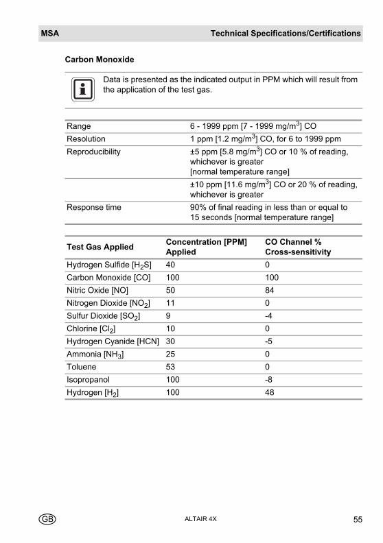
Carbon Monoxide
Data is presented as the indicated output in PPM which will result from the application of the test gas.
Range 6 - 1999 ppm [7 - 1999 mg/m3] CO
Resolution 1 ppm [1.2 mg/m3] CO, for 6 to 1999 ppm
Reproducibility ±5 ppm [5.8 mg/m3] CO or 10 % of reading, whichever is greater [normal temperature range]
±10 ppm [11.6 mg/m3] CO or 20 % of reading, whichever is greater
Response time 90% of final reading in less than or equal to 15 seconds [normal temperature range]
Test Gas AppliedConcentration [PPM] Applied
CO Channel % Cross-sensitivity
Hydrogen Sulfide [H2S] 40 0
Carbon Monoxide [CO] 100 100
Nitric Oxide [NO] 50 84
Nitrogen Dioxide [NO2] 11 0
Sulfur Dioxide [SO2] 9 -4
Chlorine [Cl2] 10 0
Hydrogen Cyanide [HCN] 30 -5
Ammonia [NH3] 25 0
Toluene 53 0
Isopropanol 100 -8
Hydrogen [H2] 100 48
MSATechnical Specifications/Certifications
ALTAIR 4X56 GB
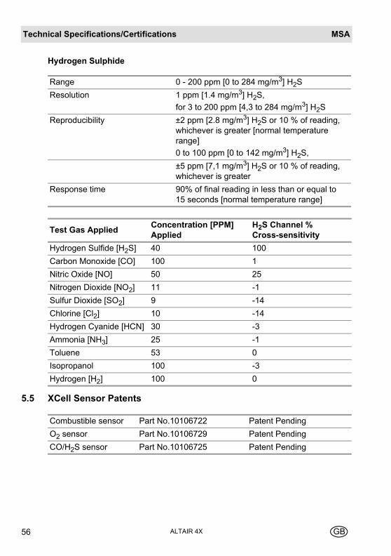
Hydrogen Sulphide
5.5 XCell Sensor Patents
Range 0 - 200 ppm [0 to 284 mg/m3] H2S
Resolution 1 ppm [1.4 mg/m3] H2S,
for 3 to 200 ppm [4,3 to 284 mg/m3] H2S
Reproducibility ±2 ppm [2.8 mg/m3] H2S or 10 % of reading, whichever is greater [normal temperature range]
0 to 100 ppm [0 to 142 mg/m3] H2S,
±5 ppm [7,1 mg/m3] H2S or 10 % of reading, whichever is greater
Response time 90% of final reading in less than or equal to 15 seconds [normal temperature range]
Test Gas AppliedConcentration [PPM] Applied
H2S Channel % Cross-sensitivity
Hydrogen Sulfide [H2S] 40 100
Carbon Monoxide [CO] 100 1
Nitric Oxide [NO] 50 25
Nitrogen Dioxide [NO2] 11 -1
Sulfur Dioxide [SO2] 9 -14
Chlorine [Cl2] 10 -14
Hydrogen Cyanide [HCN] 30 -3
Ammonia [NH3] 25 -1
Toluene 53 0
Isopropanol 100 -3
Hydrogen [H2] 100 0
Combustible sensor Part No.10106722 Patent Pending
O2 sensor Part No.10106729 Patent Pending
CO/H2S sensor Part No.10106725 Patent Pending
Ordering InformationMSA
ALTAIR 4XGB 57
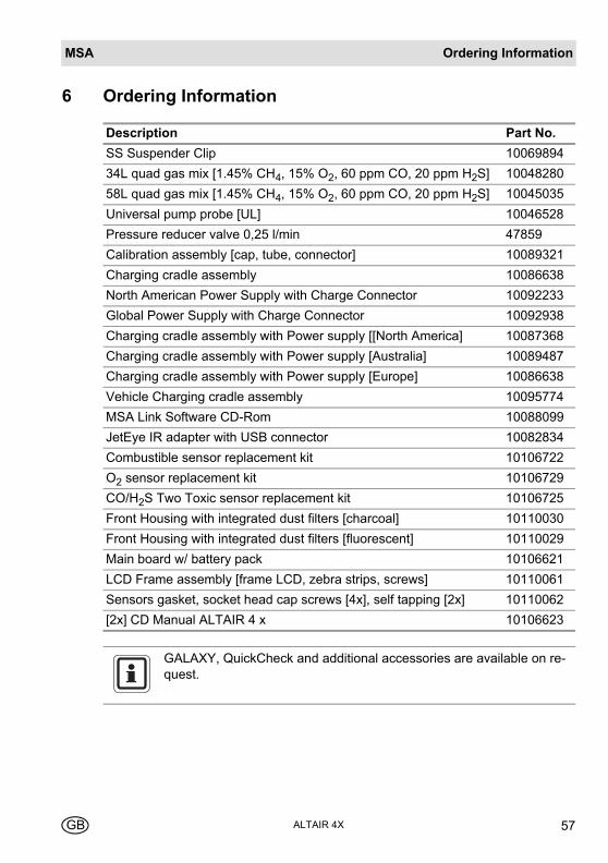
6 Ordering Information
Description Part No.
SS Suspender Clip 10069894
34L quad gas mix [1.45% CH4, 15% O2, 60 ppm CO, 20 ppm H2S] 10048280
58L quad gas mix [1.45% CH4, 15% O2, 60 ppm CO, 20 ppm H2S] 10045035
Universal pump probe [UL] 10046528
Pressure reducer valve 0,25 l/min 47859
Calibration assembly [cap, tube, connector] 10089321
Charging cradle assembly 10086638
North American Power Supply with Charge Connector 10092233
Global Power Supply with Charge Connector 10092938
Charging cradle assembly with Power supply [[North America] 10087368
Charging cradle assembly with Power supply [Australia] 10089487
Charging cradle assembly with Power supply [Europe] 10086638
Vehicle Charging cradle assembly 10095774
MSA Link Software CD-Rom 10088099
JetEye IR adapter with USB connector 10082834
Combustible sensor replacement kit 10106722
O2 sensor replacement kit 10106729
CO/H2S Two Toxic sensor replacement kit 10106725
Front Housing with integrated dust filters [charcoal] 10110030
Front Housing with integrated dust filters [fluorescent] 10110029
Main board w/ battery pack 10106621LCD Frame assembly [frame LCD, zebra strips, screws] 10110061
Sensors gasket, socket head cap screws [4x], self tapping [2x] 10110062
[2x] CD Manual ALTAIR 4 x 10106623
GALAXY, QuickCheck and additional accessories are available on re-quest.

MSAAppendix
ALTAIR 4X58 GB
7 Appendix
7.1 Start Up Sequence [Power on]
H2SCO
H2SCO
COMB/EX COMB/EX
COMB/EX O2
H2SCO
COMB/EX O2
H2SCO CO
Begin Normal Operation
From Power on (Press )
COMB/EX
H2SCO
COMB/EX O2
H2SCO
COMB/EX O2
H2SCO
AppendixMSA
ALTAIR 4XGB 59
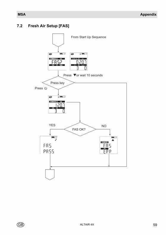
7.2 Fresh Air Setup [FAS]
Press key
Press
From Start Up Sequence
or wait 10 seconds
Press
FAS OK?YES NO
MSAAppendix
ALTAIR 4X60 GB
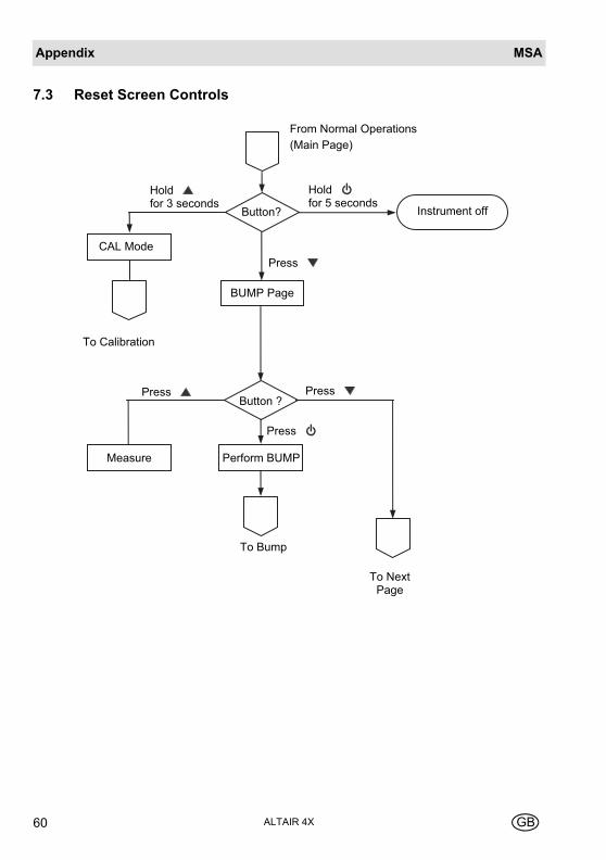
7.3 Reset Screen Controls
To Bump
Button ?
Button?
Holdfor 3 seconds
Holdfor 5 seconds
Instrument off
CAL Mode Press
BUMP Page
Press Press
Press
Perform BUMPMeasure
To Next Page
From Normal Operations (Main Page)
To Calibration

AppendixMSA
ALTAIR 4XGB 61
COMB/EX O2
H2SCO
COMB/EX O2
H2SCO
From previous page
Button ?
Press Press
O2
O2
Button ?
Press Press
H2SCO
H2SCO
Button ?
Press Press
Press
Press
Press
H2SCO
H2SCO
Button ?
Press
Press
Press
To Time and Date
Main Page
MSAAppendix
ALTAIR 4X62 GB
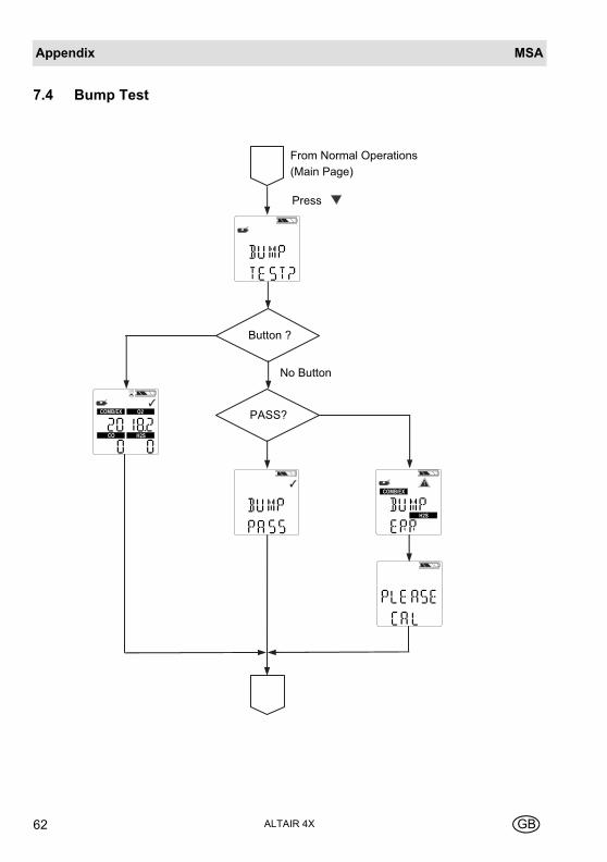
7.4 Bump Test
COMB/EX O2
H2SCO
COMB/EX
H2S
Button ?
From Normal Operations (Main Page)
Press
No Button
PASS?

AppendixMSA
ALTAIR 4XGB 63
7.5 Options Setup
Password Correct?
NOYES
Button?orSetup
COMB/EX O2
H2SCO
COMB/EX O2
H2SCO
To Sensor Setup
To CAL Setup
COMB/EX O2
H2SCO
To Alarm SetupTo Time/
Date Setup
To MainPage
FromDate/Time Setup
FromAlarmSetup
FromCALSetup
MSAAppendix
ALTAIR 4X64 GB
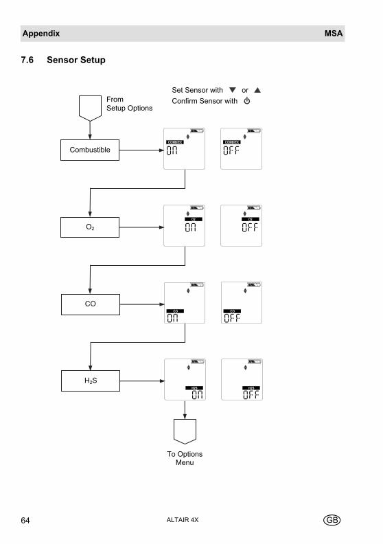
7.6 Sensor Setup
H2S
COMB/EX
CombustibleCOMB/EX
O2
O2
O2
COCO
CO
H2SH2S
To Options Menu
FromSetup Options
Set Sensor with orConfirm Sensor with

AppendixMSA
ALTAIR 4XGB 65
7.7 Calibrations
ZERO CAL
Perform ZERO CAL?
SPAN CAL
Perform SPAN CAL?
CAL COMPLETE Return to Normal Operation
Press
Press
Press
Press
From Measure Page when is held for 3 seconds
CO
COMB/EX O2
H2S CO
Press
YES
NO

MSAAppendix
ALTAIR 4X66 GB
7.8 Alarm Setup
COMB/EXCOMB/EX
From Setup Options
Combustible
O2
CO
H2S
ToTime/DateSetup
O2O2
COCO COCO
H2SH2S H2SH2S
Set Alarms on or off
Set Alarms with or Confirm Alarms with
AppendixMSA
ALTAIR 4XGB 67
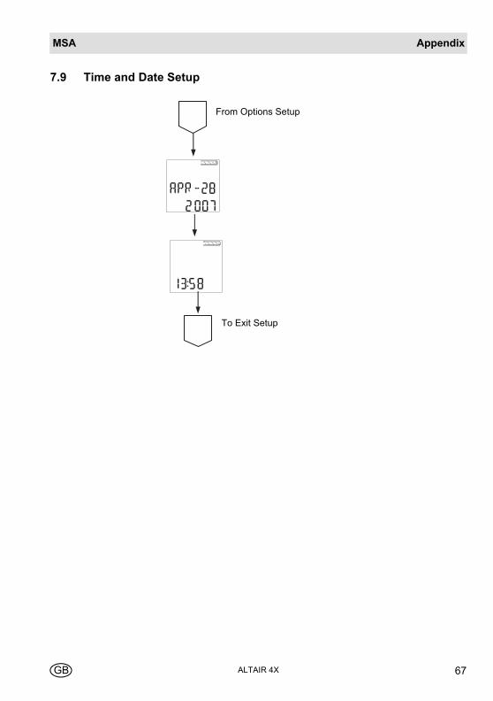
7.9 Time and Date Setup
From Options Setup
To Exit Setup
MSA in Europe[ www.msa-europe.com & www.msa-gasdetection.com ]
Northern Europe Southern Europe Eastern Europe Central Europe
NetherlandsMSA NederlandKernweg 201627 LH HoornPhone +31 [229] 25 03 03Fax +31 [229] 21 13 [email protected]
BelgiumMSA BelgiumDuwijckstraat 172500 LierPhone +32 [3] 491 91 50Fax +32 [3] 491 91 [email protected]
Great BritainMSA BritainLochard HouseLinnet WayStrathclyde Business ParkBELLSHILL ML4 3RAScotlandPhone +44 [16 98] 57 33 57Fax +44 [16 98] 74 [email protected]
SwedenMSA NORDICKopparbergsgatan 29214 44 MalmöPhone +46 [40] 699 07 70Fax +46 [40] 699 07 [email protected]
MSA SORDINRörläggarvägen 833153 VärnamoPhone +46 [370] 69 35 50Fax +46 [370] 69 35 [email protected]
FranceMSA GALLETZone Industrielle Sud01400 Châtillon sur ChalaronnePhone +33 [474] 55 01 55Fax +33 [474] 55 47 [email protected]
ItalyMSA ItalianaVia Po 13/1720089 Rozzano [MI]Phone +39 [02] 89 217 1Fax +39 [02] 82 59 [email protected]
SpainMSA EspañolaNarcís Monturiol, 7Pol. Ind. del Sudoeste08960 Sant-Just Desvern[Barcelona]Phone +34 [93] 372 51 62Fax +34 [93] 372 66 [email protected]
PolandMSA Safety Polandul. Wschodnia 5A05-090 Raszyn k/WarszawyPhone +48 [22] 711 50 33Fax +48 [22] 711 50 [email protected]
Czech RepublicMSA Safety CzechPikartská 1337/7716 07 Ostrava-RadvanicePhone +420 [59] 6 232222Fax +420 [59] 6 [email protected]
HungaryMSA Safety HungariaFrancia út 101143 BudapestPhone +36 [1] 251 34 88Fax +36 [1] 251 46 [email protected]
RomaniaMSA Safety RomaniaStr. Virgil Madgearu, Nr. 5Ap. 2, Sector 1014135 BucurestiPhone +40 [21] 232 62 45Fax +40 [21] 232 87 [email protected]
RussiaMSA Safety RussiaPokhodny Proezd, 14 125373 MoscowPhone +7 [495] 921 1370/74Fax +7 [495] 921 [email protected]
GermanyMSA AUERThiemannstrasse 112059 BerlinPhone +49 [30] 68 86 0Fax +49 [30] 68 86 15 [email protected]
AustriaMSA AUER AustriaKaplanstrasse 83430 TullnPhone +43 [22 72] 63 360Fax +43 [22 72] 63 360 [email protected]
SwitzerlandMSA SchweizEichweg 68154 OberglattPhone +41 [43] 255 89 00Fax +41 [43] 255 99 [email protected]
European International Sales[Africa, Asia, Australia, Latin America, Middle East]
MSA EUROPEThiemannstrasse 112059 BerlinPhone +49 [30] 68 86 55 5Fax +49 [30] 68 86 15 [email protected]