Operating, Maintenance & Parts Manual T 250 Kg. To 2000 Kg ...
48
83877 ENTERTAINMENT ® Manual No. E627 Operating, Maintenance & Parts Manual 1/4 To 2 Ton 250 Kg. To 2000 Kg. Columbus McKinnon Corporation CM Entertainment Division 140 John James Audubon Parkway Amherst, New York 14228-1197 1-800-888-0985 1-716-689-5400 cmrigging.com ®
Transcript of Operating, Maintenance & Parts Manual T 250 Kg. To 2000 Kg ...

83877
EENN
TTEE
RRTT
AAIINN
MMEE
NNTT
®
Manual No. E627
Operating, Maintenance & PPaarrttss MMaannuuaall11//44 TToo 22 TToonn
225500 KKgg.. TToo 22000000 KKgg..
Columbus McKinnon CorporationCM Entertainment Division
140 John James Audubon ParkwayAmherst, New York 14228-1197
1-800-888-09851-716-689-5400cmrigging.com
®

LIMITATION OF WARRANTIES, REMEDIES AND DAMAGES
THE WARRANTY STATED BELOW IS GIVEN IN PLACE OF ALLOTHER WARRANTIES, EXPRESS OR IMPLIED, OF MER-CHANTABILITY, FITNESS FOR A PARTICULAR PURPOSE, OROTHERWISE, NO PROMISE OR AFFIRMATION OF FACT MADEBY ANY AGENT OR REPRESENTATIVE OF SELLER SHALLCONSTITUTE A WARRANTY BY SELLER OR GIVE RISE TOANY LIABILITY OR OBLIGATION.
Seller warrants that on the date of delivery to carrier the goods arefree from defects in workmanship and materials.
SELLER’S SOLE OBLIGATION IN THE EVENT OF BREACH OFWARRANTY OR CONTRACT OR FOR NEGLIGENCE OR OTHER-WISE WITH RESPECT TO GOODS SOLD SHALL BE EXCLUSIVE-LY LIMITED TO REPAIR OR REPLACEMENT, F.O.B. SELLER’SPOINT OF SHIPMENT, OF ANY PARTS WHICH SELLER DETER-MINES TO HAVE BEEN DEFECTIVE or if Seller determines thatsuch repair or replacement is not feasible, to a refund of the pur-chase price upon return of the goods to Seller.
Any action against Seller for breach of warranty, negligence or oth-erwise, must be commenced within one year after such cause ofaction occurs.
NO CLAIM AGAINST SELLER FOR ANY DEFECT IN THE GOODSSHALL BE VALID OR ENFORCEABLE UNLESS BUYER’S WRIT-TEN NOTICE THEREOF IS RECEIVED BY SELLER WITHIN ONEYEAR FROM THE DATE OF SHIPMENT.Seller shall not be liable for any damage, injury or loss arising out of
the use of the goods if, prior to such damage, injury or loss, suchgoods are (1) damaged or misused following Seller’s delivery to car-rier; (2) not maintained, inspected, or used in compliance with appli-cable law and Seller’s written instructions and recommendations; or(3) installed, repaired, altered or modified without compliance withsuch law, instructions or recommendations.UNDER NO CIRCUMSTANCES SHALL SELLER BE LIABLE FORINCIDENTAL OR CONSEQUENTIAL DAMAGES AS THOSETERMS ARE DEFINED IN SECTION 2-715 OF THE UNIFORMCOMMERCIAL CODE.
INDEMNIFICATION AND SAFE OPERATIONBuyer shall comply with and require its employees to comply withdirections set forth in instructions and manuals furnished by Sellerand shall use and require its employees to follow such instructionsand manuals and to use reasonable care in the use and mainte-nance of the goods. Buyer shall not remove or permit anyone toremove any warning or instruction signs on the goods. In the eventof personal injury or damage to property or business arising fromthe use of the goods, Buyer shall within 48 hours thereafter giveSeller written notice of such injury or damage. Buyer shall cooperatewith Seller in investigating any such injury or damage and in thedefense of any claims arising therefrom.
If Buyer fails to comply with this section or if any injury or damage iscaused, in whole or in part, by Buyer’s failure to comply with appli-cable federal or state safety requirements, Buyer shall indemnifyand hold Seller harmless against any claims, loss or expense forinjury or damage arising from the use of the goods.
®
!! WARNINGAlterations or modifications of equipment and use of non-factory repair parts can lead to dangerous operation andinjury.
TO AVOID INJURY:• Do not alter or modify equipment.• Do use only CM replacement parts.
Columbus McKinnon CorporationCM Entertainment Division
140 John James Audubon ParkwayAmherst, New York 14228-1197
1-800-888-09851-716-689-5400
Fax 1-716-689-5644cmrigging.com
© 2006 Columbus McKinnon Corp. 8/06 Printed in USA
All Columbus McKinnon (CM®) Lodestar Electric ChainHoists are thoroughly inspected and performance testedprior to shipment. If any properly maintained hoist developsa performance problem due to a material or workmanshipdefect, as verified by CM, repair or replacement of the unitwill be made to the original purchaser without charge. Thisrepair/replacement policy applies only to Lodestar Hoistsinstalled, maintained and operated as outlined in this manual,and specifically excludes parts subject to normal wear,abuse, improper installation, improper or inadequate mainte-nance, hostile environmental effects and unauthorizedrepairs/modifications.
We reserve the right to change materials or design, if, in ouropinion, such changes will improve our product. Abuse,repair by an unauthorized person, or use of non-CMreplacement parts voids the guarantee and could lead to dangerous operation. For full Terms of Sale, see SalesOrder Acknowledgement. Also, refer to the back cover forLimitations of Warranties, Remedies and Damages, andIndemnification and Safe Operation.
GENERAL INFORMATION

CM HOIST PARTS AND SERVICES ARE AVAILABLE WORLD WIDEAs a CM Hoist user, you are assured of reliable repair and parts services through a network of Master Parts Depots and Service Centers that are strate-gically located World Wide. These facilities have been selected on the basis of their demonstrated ability to handle all parts and repair requirementspromptly and efficiently.
Below is a list of the Master Parts Depots and Entertainment Hoist Service Stations. To quickly obtain the name of the U.S. Service Center located near-est you, call (800) 888-0985. Fax: (716) 689-5644.
ARGENTINAIFAN RENIERI Y CIA SA.Aristobulo Del Valle 1933/43(1295) Buenos Aires, ArgentinaUPSTAGE, S.A.Warnes 2351(1427) Capital FederalBuenos Aires, Argentina
AUSTRIATüchler GmbHRennbahnweg 78Vienna 1220Austria(43)-1-400-10-23Fax (43)-1-400-10-20
AUSTRALIAPWB ANCHOR441 Grimshaw StreetBundoora Victoria,Australia 3083(61)-39-467-2933Fax (61)-39-467-4320
BRASILHABITASUL S.A. COMERCIOEXTERI157-Sala 130290.010.030Porto Alegre-RS-BrasilROSCO DO BRASILRua Antonio De Barros #827Cep 03401-000Sao Paulo, Brasil
BOLIVIASONILUM ILUMINACION YSONIDOTucuman 20 (6 Este) EquipetrolSanta Cruz De La SierraBolivia
CHINAHANGZHOU, LILA LIFT./LASH. CO.Zhijiang Hi-Tech ZoneHangzhou, Zhejiang, 310053P.R. Of China(86)-571-8669-6946Fax (86)-571-8669-6219
ENGLANDTOMCAT UK Ltd.Unit 2, Skiddaw RdCroft Business ParkBromborough, Wirral CH62 3RBUnited Kingdom(44)-151-482-3100Fax (44)-151-482-3111
FRANCESONOSSAvenue De La RotondeSac Postal 959465 Lomme, FranceLomme (Cedex)(33)-3-20-00-92-10Fax (33)-3-20-00-92-11
GERMANYLMP LICHTTECHNIKGildestrasse 5549477 Ibbenburen, GermanyPFAFF SILBERBLAUPostfach 102229Augsburg 86012, GermanyHOAC HANDELS GMBHPferdsweide 39CNordrhein-Westfalen, DeutschlaMores, Germany 47441(49)-2841-90-828-28Fax (49) 2841-90-828-70
ISRAELGILON SUPPLY (1946) LTD21, Frug St.Tel-Aviv, 63417, Israel
ITALYLitec SrlVia Venier 5230020 Macron (Ve)Italy(39)-041-596-0000Fax (39) 041-595-1082
JAPANKATSUYAMA KIKAI LTD104-18 Honjounishi 2Chome, Higashiosaka, Osaka, 578-0965Japan(81)-6-6747-6390Fax (81)-6-6748-2039SHIMIZU OCTO INC1-4-1 Shimoochiai, Shinjuku-KuTokyo 161-0033Japan(81)-0-3-3360-7743Fax (81)-0-3-3360-1664
MEXICOCOLUMBUS McKINNONDe Mexico S.A. De C.V.Venustiano Carranza #301Santiago TianguistencoC.P. 52600, Mexico
NETHERLANDSLouis Reyners B.V.Symon Spiersweg 13APostbus 21181500 GC ZaandamNetherlands(31)-75-650-4750Fax (31)-75-650-4760
SINGAPORECSP PRODUCTIONS (PTE) LTDNo 3 Upper Aljunied Link 05-04Joo Seng Warehouse Tower B Singapore 367902(65)-6283-0220Fax (65)-6284-0220
CALIFORNIAOTTO SYSTEMS, INC.12010 Bloomfield Ave.Sante Fe Springs, CA 90670562/462-1612 or 800/596-7392Fax 562/462-1617or7656 Las Positas RoadLivemore, CA 94551925/245-8800 or 800/508-6886Fax 925/245-8804STAGE RIGGING2690 Middlefield Road, Unit FRedwood City, CA 94063650/299-1189Fax 650/299-1617
FLORDIANATIONAL PRODUCTIONS SERVICES9561 Satellite Blvd.Orlando, FL 32837407/857-6446Fax 407/857-6264
GEORGIAATLANTA RIGGING SYSTEMS1270 Tacoma Dr.Atlanta, GA 30318404/355-4370Fax 404/355-4360ACE INDUSTRIES, INC.6295 McDonough DriveNorcross, GA 30093770/441-0898 or 800/733-2231Fax 800/628-3648
ILLINOISREED RIGGING2309 S. Keeler Ave.Chicago IL 60623773/521-7333Fax 773/521-1709
INDIANAHORNER ELECTRIC COMPANY, INC.1521 East Washington StreetIndianapolis, IN 46201317/639-4261Fax 317/639-4342
IOWAVMI HOIST & CRANE SERVICES901 17th Street NECedar Rapids, IA 52406319/365-4662Fax 319/365-8075
LOUISIANABEERMAN PRECISION, INC.4206 Howard Ave.New Orleans, LA 70125504/486-9391Fax 504/486-7482
MASSACHUSETTSABEL DISTRIBUTORS, INC.50 Parker Street, Unit 2Newburyport, MA 01950978/463-0700Fax 978/463-5200
MISSOURIINDEPENDENT ELECTRIC MACHINERY4425 Oliver StreetKansas City, MO 66106913/362-1155Fax 913/904-3330
NEVADASILVER STATE WIRE ROPE5380 S. Valley View Blvd.Suite ALas Vegas, NV 89118702/597-2010Fax 702/896-1977TOMCAT USA, INC4020 Ali Baba LaneBldg. D. Suite ALas Vegas, NV 89118702/798-6200Fax 702/798-6225
NEW JERSEYSHUPPER-BRICKLE EQUIPMENT CO.2394 Route 130, Suite CDayton, NJ 08810732/438-3888Fax 732/438-3889
NEW YORKVOLLAND ELECTRIC EQUIPMENT CO.75 Innsbruck DriveBuffalo, NY 14227716/656-9900Fax 716/656-8898/8899
NORTH CAROLINATEAM SESCO2225 Freedom DriveCharlotte, NC 28208704/372-4832 or 800/487-3726Fax 704/358-1098
OHIOMAZZELLA LIFTING TECHNOLOGIES21000 Aerospace ParkwayCleveland, OH 44142440/239-5700 or 800/362-4601Fax 440/239-5707
PENNSYLVANIAAMICK ASSOCIATES, INC.11 Sycamore StreetCarnegie, PA 15106-0529412/429-1212 or 800/445-9456Fax 412/429-0191RAM MOTORS & CONTROLS, INC.5460-B Pottsville PikeLeesport, PA 19533610/916-8000 or 877/916-8018Fax 610/916-7957MOUNTAIN PRODUCTIONS80 New Fredrick St.Wilkes-Barre, PA 18702570/826-5566 or 800/733-5553Fax 570/824-6139
TEXASABEL EQUIPMENT CO., INC.3710 Cavalier DriveGarland, TX 75042972/272-7706Fax 972/272-6955HYDRAULIC EQUIPMENT SERVICES,INC.1021 North San Jacinto StreetHouston, TX 77002713/228-9601 Fax 713/228-0931SHIMIZU INTERNATIONAL PRO-DUCTION SERVICES, INC.1500 East Belt Line RoadCarrollton, TX. 75006
TOMCAT USA2160 Commerce DrMidland TX 79703432/694-7070Fax 432/689-3805
WISCONSINTRESTER HOIST & EQUIPMENT, INC.W136 N4863 Campbell DriveMenomonee Falls, WI 53051262/790-0700 or 800/234-6098Fax 262/790-1009
ALBERTABENNETT & EMMOTT, LTD.18131 118th AvenueEdmonton, Alberta T5S 1M8403/454-9000Fax 403/454-8990
CHRISTIE LITES2610 3rd AvenueCalagary, AB T2A 2L5403/243-2688Fax 403/243-2689
MASTER PARTS DEPOT
i
“ENTERTAINMENT HOIST”SERVICE STATIONS
“ENTERTAINMENT HOIST”SERVICE STATIONS
ALBERTA**COLUMBUS McKINNON, LTD.10311-174th StreetEdmonton, Alberta T5S 1H1800/263-1997Fax 403/486-6160
BRITISH COLUMBIAFLECK BROTHERS, LTD.4084 McConnel CourtBurnaby, British Columbia V5A 3N7CHRISTIE LITES3686 Bainbridge Ave.Burnaby, BC V5C 5A9604/255-9943Fax 604/255-9194STUDIO CITY RENTALS2050 Alfa AvenueBurnaby, BC V5C 5A9604/291-9414Fax 604/292-6786
MANITOBAKING’S ELECTRIC MOTORS, INC.633 Tyne AvenueWinnipeg, Manitoba R2L 1J5204/663-5332Fax 204/663-4059
NOVA SCOTIA*W & A MOIR95 Ilsley Ave.Burnside Park, Nova Scotia B3B 1L5902/468-7720Fax 902/468-3777
ONTARIOCHRISTIE LITES102-15 North Queen St.Toronto, ON M8Z 6C1416/644-1010Fax 416/644-0404PRG LIGHTING2480 Tedlo St.Mississaua, ON L5A 3V3905/270-9050Fax 905/270-2590*R & W HOIST REPAIR, LTD.790 Redwood SquareUnits 5, 6, & 7Oakville, Ontario L6L 6N3905/825-5500Fax 905/825-5315STUDIO CITY RENTALS75 Commissioner St.Toronto, ON M5A 1A6416/465-6434Fax 416/465-7008*TORONTO ELECTRIC HOIST SALES & SERVICE9 CoDeco CourtNorth York, Ontario M3A 1A1416/386-0820Fax 416/386-0821*MASLACK SUPPLY, LTD.488 Falconbridge RoadSudbury, Ontario P3A 4S4705/566-1270Fax 705/566-4208*COLUMBUS McKINNON, LTD.P.O. Box 110610 Brook Road, NorthCobourg, Ontario K9A 4W5905/372-0153Fax 905/372-3078
QUEBEC*HERCULES SLING & CABLE3800 TransCanada HighwayPointe-Claire, Quebec H9R 1B1514/428-5511514/48631-5511Fax 514/428-5555*LEGER PALANS ET OUTILLAGES, INC.7995-17th Ave.Montreal, Quebec H1Z 3R2514/376-3050Fax 514/376-0657
SOLOTECH4820 4th AvenueMontreal, QC H1Y 2T8514/526-7725Fax 514/526-7729
**ARE ALSO MASTER PARTS DEPOTS
**MASTER PARTS DEPOT ONLY
“ENTERTAINMENT HOIST”SERVICE STATIONS
“ENTERTAINMENT HOIST”SERVICE STATIONS

1. NOT lift people.2. NOT allow people on unsecured load without fall protection.3. NOT exceed rated capacity of hoist.4. NOT remove or obscure any capacity or warning label.5. Check the supporting structure. The connection between the
load hook and structure. The load itself and the connection betweenthe hoist support and the load for their ability to withstand the loadsimposed with an adequate design factor.
6. Tie off the load with auxiliary chains or cables before access to the area beneath the load is permitted. As an alternative, the system may be designed such that malfunction or failure of one hoist’s load bearing components does not cause load loss and/or overloading of any other hoists in the system. Note that in such a system, hoist performance and function must be monitored visuallyor with use of load cells.
7. Read hoist manual and special instructions before installing and operating the hoist.
Successful Theatrical Hoist Operation Requires the following actions:
At the loose end, maintain a minimum of 24 inches of chain freelyhanging over the side of hoist.
Keep load chain well lubricated using Lubriplate® 10R Bar and Chain oil.
Do make sure hoist is phased properly and chain travel limits function properly.
If a chain container is used, inspect before each use for damaged,loose hardware and water drainage provisions. Make certain containerattachment hardware has an adequate design factor of a minimum of5 to 1. Also, make sure chain container is of sufficient capacity: chainchain in fully loaded container shall not exceed 75% of containerheight.
1. Maintain a firm footing or be otherwise secured when operating the hoist.
2. Check brake function by tensioning the hoist prior to each lift operation.
3. Use hook latches. Latches are to retain slings, chains, etc. under slack conditions only.
4. Make sure the hook latches are closed and not supporting any parts of the load.
5. Make sure the load is free to move and will clear all obstructions.6. Avoid swinging the load or hook.7. Make sure hook travel is in the same direction as shown on the
controls.8. Inspect the hoist regularly, replace damaged or worn parts, and
keep appropriate records of maintenance.9. Use CM parts when repairing the unit.10. Lubricate load chain per instructions in this manual.11. NOT use the hoist load limiting or warning device to measure load.12. NOT use limit switches as routine operating stops. They are
emergency devices only.13. NOT allow your attention to be diverted when operating hoist.14. NOT allow the hoist to be subjected to sharp contact with other
hoists, structures, or objects through misuse.15. NOT adjust or repair the hoist unless qualified to perform such
adjustments or repairs.
SAFETY PRECAUTIONSEach Entertainment-Lodestar Electric Hoist is built in accordance with the specifications contained herein and at the time ofmanufacture complied with our interpretation of applicable sections of the *American Society of Mechanical Engineers CodeB30.16 “Overhead Hoists”, the National Electrical Code (ANSI/NFPA 70), the Occupational Safety and Health Act, British HealthSafety Executives, TUV and CE Directive. Since OSHA states the National Electrical Code applies to all electric hoists,installers are required to provide current overload protection and grounding on the branch circuit section in keeping with thecode. Check each installation for compliance with the application, operation and maintenance sections of these articles.
The safety laws for elevators, lifting of people and for dumbwaiters specify construction details that are not incorporated in CMindustrial hoists. For such applications, refer to the requirements of applicable state and local codes, and the AmericanNational Safety Code for elevators, dumbwaiters, escalators and moving walks (ASME A17.1). Columbus McKinnonCorporation cannot be responsible for applications other than those for which CM equipment is intended.
*Copies of this Standard can be obtained from ASME Order Department, 22 Law Drive, Box 2300, Fairfield, NJ 07007-2300,U.S.A.
THIS SYMBOL POINTS OUT IMPORTANT SAFETY INSTRUCTIONS WHICH IF NOT FOL-LOWED COULD ENDANGER THE PERSONAL SAFETY AND/OR PROPERTY OF YOUR-SELF AND OTHERS. READ AND FOLLOW ALL INSTRUCTIONS IN THIS MANUAL ANDANY PROVIDED WITH THE EQUIPMENT BEFORE ATTEMPTING TO OPERATE YOURLODESTAR HOIST.
!! !! WWAARRNNIINNGG
Usage of hoists that do not involve lifting of the load onthe lower hook or using hoists in the inverted positionwithout special precaution may cause an accidentresulting in injury and/or property damage.
WWAARRNNIINNGG
Improper operation of a hoist can create a potentiallyhazardous situation which, if not avoided, could resultin death or serious injury. To avoid such a potentially hazardous situation, the operator shall:
CCAAUUTTIIOONNImproper operation of a hoist can create a potentiallyhazardous situation which, if not avoided, could resultin minor or moderate injury. To avoid such a potentiallyhazardous situation, the operator shall:
ii
!! !!
!!
!!!!
CCAAUUTTIIOONN!!
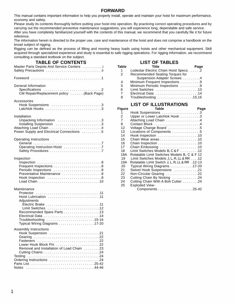
TABLE OF CONTENTSMaster Parts Depots And Service Centers . . . . . . . . . .iSafety Precautions . . . . . . . . . . . . . . . . . . . . . . . . . . . .ii
Foreword . . . . . . . . . . . . . . . . . . . . . . . . . . . . . . . . . . .1
General InformationSpecifications . . . . . . . . . . . . . . . . . . . . . . . . . . . . .2CM Repair/Replacement policy . . . . . . .(Back Page)
AccessoriesHook Suspensions . . . . . . . . . . . . . . . . . . . . . . . . .3Latchlok Hooks . . . . . . . . . . . . . . . . . . . . . . . . . . . .3
InstallationUnpacking Information . . . . . . . . . . . . . . . . . . . . . .3Installing Suspension . . . . . . . . . . . . . . . . . . . . . . .3
Attaching Load Chain . . . . . . . . . . . . . . . . . . . . . . . . . .4Power Supply and Electrical Connections . . . . . . . . . .5
Operating InstructionsGeneral . . . . . . . . . . . . . . . . . . . . . . . . . . . . . . . . . .7Operating Instruction-Hoist . . . . . . . . . . . . . . . . . . .7Safety Procedures . . . . . . . . . . . . . . . . . . . . . . . . . .7
InspectionInspection . . . . . . . . . . . . . . . . . . . . . . . . . . . . . . . .8Frequent Inspections . . . . . . . . . . . . . . . . . . . . . . . .8Periodic Inspections . . . . . . . . . . . . . . . . . . . . . . . .8Preventative Maintenance . . . . . . . . . . . . . . . . . . . .8Hook Inspection . . . . . . . . . . . . . . . . . . . . . . . . . . .8Load Chain . . . . . . . . . . . . . . . . . . . . . . . . . . . . . .10
MaintenanceProtector . . . . . . . . . . . . . . . . . . . . . . . . . . . . . . . .11Hoist Lubrication . . . . . . . . . . . . . . . . . . . . . . . . . .11Adjustments
Electric Brake . . . . . . . . . . . . . . . . . . . . . . . . . . .11Limit Switches . . . . . . . . . . . . . . . . . . . . . . . . . .12
Recommended Spare Parts . . . . . . . . . . . . . . . . . .13Electrical Data . . . . . . . . . . . . . . . . . . . . . . . . . . . .14Troubleshooting . . . . . . . . . . . . . . . . . . . . . . . .15-16Typical Wiring Diagrams . . . . . . . . . . . . . . . . . .17-20
Assembly InstructionsHook Suspension . . . . . . . . . . . . . . . . . . . . . . . . .21Gearing . . . . . . . . . . . . . . . . . . . . . . . . . . . . . . . . .22Fasteners . . . . . . . . . . . . . . . . . . . . . . . . . . . . . . .22Lower Hook Block Pin . . . . . . . . . . . . . . . . . . . . . .22Removal and Installation of Load Chain . . . . . . . .23Cutting Chains . . . . . . . . . . . . . . . . . . . . . . . . . . . .24
Testing . . . . . . . . . . . . . . . . . . . . . . . . . . . . . . . . . . . .24Ordering Instructions . . . . . . . . . . . . . . . . . . . . . . . . .24Parts List . . . . . . . . . . . . . . . . . . . . . . . . . . . . . . . .25-42Notes . . . . . . . . . . . . . . . . . . . . . . . . . . . . . . . . . .44-46
LIST OF TABLESTable Title Page
1 Lodestar Electric Chain Hoist Specs. . . . . .22 Recommended Seating Torques for
Suspension Adapter Screws . . . . . . . . .44 Minimum Frequent Inspections . . . . . . . . . .95 Minimum Periodic Inspections . . . . . . . . . .96 Limit Switches . . . . . . . . . . . . . . . . . . . . .137 Electrical Data . . . . . . . . . . . . . . . . . . . . .148 Troubleshooting . . . . . . . . . . . . . . . . . .15,16
LIST OF ILLUSTRATIONSFigure Table Page
1 Hook Suspensions . . . . . . . . . . . . . . . . . . .32 Upper or Lower Latchlok Hook . . . . . . . . . .37 Attaching Load Chain . . . . . . . . . . . . . . . . .48 Contact Block . . . . . . . . . . . . . . . . . . . . . . .412 Voltage Change Board . . . . . . . . . . . . . . . .513 Locations of Components . . . . . . . . . . . . . .514 Hook Inspection . . . . . . . . . . . . . . . . . . . .1015 Chain Wear areas . . . . . . . . . . . . . . . . . . .1016 Chain Inspection . . . . . . . . . . . . . . . . . . . .1017 Chain Embossing . . . . . . . . . . . . . . . . . . .1018 Limit Switches Models B, C & F . . . . . . . . .1218A Rotatable Limit Switches Models B, C & F 1219 Limit Switches Models J, L, R, LL & RR . . . .1219A Rotatable Limit Switch J, L, R, LL & RR .12-1320 Typical Wiring Diagrams . . . . . . . . . . .17-2021 Swivel Hook Suspensions . . . . . . . . . . . .2122 Non-Circular Gearing . . . . . . . . . . . . . . . .2223 Cutting Chain By Nicking . . . . . . . . . . . . .2424 Cutting Chain With A Bolt Cutter . . . . . . . .2425 Exploded View-
Components . . . . . . . . . . . . . . . . . 25-42
FORWARDThis manual contains important information to help you properly install, operate and maintain your hoist for maximum performance,economy and safety.Please study its contents thoroughly before putting your hoist into operation. By practicing correct operating procedures and bycarrying out the recommended preventive maintenance suggestions, you will experience long, dependable and safe service.After you have completely familiarized yourself with the contents of this manual, we recommend that you carefully file it for futurereference.The information herein is directed to the proper use, care and maintenance of the hoist and does not comprise a handbook on thebroad subject of rigging.Rigging can be defined as the process of lifting and moving heavy loads using hoists and other mechanical equipment. Skillacquired through specialized experience and study is essential to safe rigging operations. For rigging information, we recommendconsulting a standard textbook on the subject.
1

SSPPEECCIIFFIICCAATTIIOONNSSThe Lodestar Electric Chain Hoist is a highly versatile materi-als handling device that can be used to lift loads that arewithin its rated capacity. The mechanical features of thesehoists include an alloy liftwheel, Load Protector, hardenedsteel chain guides, hardened steel load chain, hardened steelgear train, life-time lubrication, forged steel hooks, and light-weight aluminum frame. The electrical features includedhoist-duty motor, rugged hoist brake, magnetic reversing con-tactor and voltage conversion board (dual voltage units).
Follow all instructions and warnings forinspecting, maintaining and operating this hoist.
The use of any hoist presents some risk of personal injury orproperty damage. That risk is greatly increased if properinstructions and warnings are not followed. Before using thishoist, each operator should become thoroughly familiar withall warnings, instructions, and recommendations in this manual.Retain this manual for future reference and use.Forward this manual to the hoist operator.Failure to operate the equipment as directed in the manualmay cause injury.
Before putting hoist into service, fill in the information below.Refer to the hoist identification plate.
MMooddeell NNuummbbeerr __________________________________
SSeerriiaall NNuummbbeer ____________________________________
PPuurrcchhaassee DDaattee __________________________________
VVoollttaaggee __________________________________________
RRaatteedd LLooaadd ______________________________________
Table 1. Specifications
Entertainment-Lodestar Electric Chain Hoists
MaximumCapacity
(Tons) Model
*LiftingSpeed
Per Min.(Feet)
*LiftingSpeed
Per Min.(M)
MotorH.P.
MotorK.W.
ShortestDistanceBetweenHooks
(Inches)
ShortestDistanceBetweenHooks (mm)
NetWeight(Lbs.)
NetWeight(Kg.)
Single Speed 230/460-3-60 or 220/380-3-50or 220/415-3-50
1/4 B 16 4.88 1/4 .186 14-1/4 362.0 57 25.81/41/2
CF
3216
9.754.88
1/21/2
.372
.37214-1/414-1/4
362.0362.0
6564
29.529.0
1/212
JLR
32168
9.754.882.44
111
.746
.746
.746
15-9/1615-9/1622-1/2
395.3395.3571.5
115117136
52.253.161.7
Single Speed 230/460-3-60 or 220/380-3-50or 220/415-3-50
1 LL 32 9.75 2 1.49 15-9/16 395.3 121 54.9
2 RR 16 4.88 2 1.49 22-13/16 579.4 136 61.7
*Lifting and travel speeds listed are for 60 Hertz units. For50 Hertz units, these speeds will be 5/6 of those listed.
2

HOOK SUSPENSIONSSwivel and rigid type hook suspensions (see Figure 1) areavailable for all Lodestar Electric Hoists. However, swiveltype hook suspensions are normally recommended for mostapplications.
UNPACKING INFORMATIONWhen received, the hoist should be carefully inspected fordamage which may have occurred during shipment or han-dling. Check the hoist frame for dents or cracks, the externalcords for damaged or cut insulation, the control station for cutor damaged enclosure, and inspect the load chain for nicksand gouges. If shipping damage has occurred, refer to thepacking list envelope on the carton for claim procedure.
Before using the hoist, make sure the voltage change board(Key# 627-1013) is connected for the intended power supplythe hoist is to be operated.
NOTE: To assure long life and top performance, be sureto follow the load chain lubricating instructions on page11.
INSTALLING THE SUSPENSION
A. Single Reeved Units:Remove the hook suspension from its carton and the twosuspension screws. Place the suspension assembly into therecess on top of the hoist so that the adapter body follows thecontour of the hoist. Insert the suspension screws throughthe holes in the adapter and hand thread these into the selflocking nuts enclosed in the hoist. The screws will turn freelyinto the nuts until the last 1/4” (6.35 mm) of travel, duringwhich the resistance of the nut locking collar will be encoun-tered. Securely tighten the screws to the recommended seat-ing torque (see Table 2) using a 12 point socket (½” (13mm)socket) which fits the head of the screw.
LATCHLOK® HOOKSCM’s Latchlok hooks (see Figure 2) are available to replacethe standard upper and lower hooks used on the LodestarElectric Hoists.
B. Double Reeved Units:Remove the hook suspension from its carton and the twosuspension screws, dead end pin, washer and cotter pin. Itshould be noted that the suspension includes a dead end boltand block for supporting the dead end of the load chain asshown in Figure 7.
Place the suspension assembly into the recess on top of thehoist. The dead end block should project through the bottomof the hoist with the pin hole and slot aligned to the under-side of the hoist as shown in Figure 7. If these are notaligned as shown, lift the head of the bolt from the hexrecess in the adapter and turn the bolt and block assemblyand reseat the bolt head to obtain the proper alignment. Donot change the position of the dead end block on the bolt toattain this alignment.
Check the position of the pin hole in the dead end block tomake sure it has not been disturbed from its factory setting.The distance from the top of the pin hole to the bottom of thehoist should not exceed 7/16” (11.11 mm) for the Models R andRR. If the distance is not correct, adjust the position of thedead end block to obtain the proper distance (see Page 21).
INSTALLATION
ACCESSORIES
Figure 1. Hook Suspensions Figure 2. Upper or Lower Latchlok® Hook
3
CCAAUUTTIIOONNUSE OF IMPACT TOOLS (ELECTRIC OR PNEUMATIC)MAY CAUSE PREMATURE FAILURE OF ATTACHINGHARDWARE.
!!

Now, insert the suspension screws through the holes in theadapter and hand thread these into the self locking nutsenclosed in the hoist frame. The screws will turn freely intothe nut until the last 1/4” (6.35mm) of travel during whichthe resistance of the nut locking collar will be encountered.Securely tighten the screws to the recommended seatingtorque (see Table 2) using a 12 point socket which fits thehead of the screw.The dead end of the load chain is temporarily positioned (afew links from the end) by a wire tie. Do not remove this tiebefore attaching the chain to the dead end block. (See Fig.7).
Table 2. Recommended Seating Torques For SuspensionAdapter Screws
ATTACHING LOAD CHAIN
The Model R & RR are shipped with the dead end of the loadchain temporarily connected to the bottom of the hoist by awire tie (1) as shown in Figure 7. The clip is located a few linksfrom the end of the chain, and it should not be removed untilthe chain is to be attached to the dead end block (2). To attachthe chain to the dead end block, proceed as follows:
1. Suspend the hoist from an adequate support.2. The hoist is shipped with the dead end of the load chain
temporarily positioned a few links from the end by a light wire clip (1) as shown in Figure 7. Do not remove this clipuntil the chain is secured.
3. Remove the clip (1) by inserting a screw driver blade through a chain link and levering against the bottom of the hoist. Slide the contact block up the chain until it is against the bottom of the hoist and the dead end block isprojecting through the square opening in the bottom of the block. Insert the last link of the load chain, making sure there are no twists between the hook block and thedead end block, into the dead end block. Push the contact block up slightly and secure the load chain to thedead end block using the dead end pin, washer andcotter pin furnished with the suspension. The dead end pin also supports the contact block (See Figure 8).
4. Do not remove the wire ties from the load chain at this time.
Models No’s Screw SizeRecommendedSeating Torque
B, C & F 3/8”-16UNC-2A 40.7 to 61.0 Nm(30 to 45 lb. ft.)
J, L, R, LL & RR 1/2”-20UNF-2A 54.2 to 108.5 Nm(40 to 80 lb. ft.)
1. Wire Clip 7. Chain guide2. Dead end block 8. Loose end link3. Suspension assembly 9. Liftwheel4. Suspension self-locking nut 10. Gear housing5. Dead end bolt 11. Loose end screw
and lockwasher6. Load Chain(Do not order parts by these numbers. See parts list).
WWAARRNNIINNGGUsing other than CM supplied high strength suspensionscrews to attach the suspension adapter to the hoist maycause the screws to break and allow the hoist and load tofall.
TO AVOID INJURY:Use only the CM supplied suspension screws to attach thesuspension to the hoist and hand torque these screws tothe recommended seating torque as specified above.DO NOT apply any type of lubricant to the threads of thesescrews. Lubricating the threads will reduce the effort to seatthe screws and as a result, tightening the screws to the aboverecommended torque may break the screw, damage the sus-pension adapter, strip the nuts and/or damage the hoistframe.
!!
Figure 7. Attaching Load Chain Models R and RR
4
3
5
6DeadEnd
2ContactBlock
Removed ForClarity
4
8LooseEnd
11
10
9
ContactBlock
Figure 8. Contact Block Used On Models R & RR.
CCAAUUTTIIOONNUSE OF IMPACT TOOLS (ELECTRIC OR PNEUMATIC)MAY CAUSE PREMATURE FAILURE OF ATTACHINGHARDWARE.
!!
7
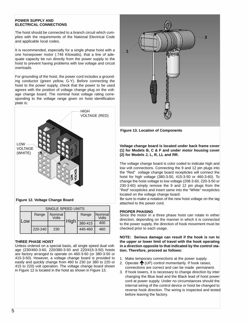
POWER SUPPLY AND ELECTRICAL CONNECTIONS
The hoist should be connected to a branch circuit which com-plies with the requirements of the National Electrical Codeand applicable local codes.
It is recommended, especially for a single phase hoist with aone horsepower motor (.746 Kilowatts), that a line of ade-quate capacity be run directly from the power supply to thehoist to prevent having problems with low voltage and circuitoverloads.
For grounding of the hoist, the power cord includes a ground-ing conductor (green yellow, G-Y). Before connecting thehoist to the power supply, check that the power to be usedagrees with the position of voltage change plug on the volt-age change board. The nominal hoist voltage rating corre-sponding to the voltage range given on hoist identificationplate is:
THREE PHASE HOIST Unless ordered on a special basis, all single speed dual volt-age (230/460-3-60, 220/380-3-50 and 220/415-3-50) hoistsare factory arranged to operate on 460-3-60 (or 380-3-50 or415-3-50). However, a voltage change board is provided toeasily and quickly change from 460 to 230 (or 380 to 220 or415 to 220) volt operation. The voltage change board shownin Figure 12 is located in the hoist as shown in Figure 13.
Voltage change board is located under back frame cover(1) for Models B, C & F and under motor housing cover(2) for Models J, L, R, LL and RR.
The voltage change board is color coded to indicate high andlow volt connections. Connecting the 9 and 12 pin plugs intothe “Red” voltage change board recepticles will connect thehoist for high voltage (380-3-50, 415-3-50 or 460-3-60). Tochange the hoist voltage to low voltage (208-3-60, 220-3-50 or230-3-60) simply remove the 9 and 12 pin plugs from the“Red” recepticles and insert same into the “White” recepticleslocated on the voltage change board.Be sure to make a notation of the new hoist voltage on the tagattached to the power cord.
PROPER PHASINGSince the motor in a three phase hoist can rotate in eitherdirection, depending on the manner in which it is connectedto the power supply, the direction of hook movement must bechecked prior to each usage.
NOTE: Serious damage can result if the hook is run tothe upper or lower limit of travel with the hook operatingin a direction opposite to that indicated by the control sta-tion. Therefore, proceed as follows:
1. Make temporary connections at the power supply.2. Operate (UP) control momentarily. If hook raises,
connections are correct and can be made permanent.3. If hook lowers, it is necessary to change direction by inter
changing the Blue lead and the Black lead of hoist powercord at power supply. Under no circumstances should theinternal wiring of the control device or hoist be changed toreverse hook direction. The wiring is inspected and tested before leaving the factory.
SINGLE SPEED UNITS
LowRange Nominal
VoltsHigh
Range NominalVolts
380-415 400
220-240 230 440-460 460
5
Figure 12. Voltage Change Board
Figure 13. Location of Components
2
1
HIGHVOLTAGE (RED)
LOWVOLTAGE (WHITE)

Do not force the Lodestar Protector to compensate forimproperly adjusted limit switches or reverse voltage phasing.
CHECKING FOR TWIST IN LOAD CHAIN Models R, RRThe best way to check for this condition is to run the lowerhook, without a load, up to within about 2 feet (.61 Meters) ofhoist. If the dead end of the chain has been properly installed,a twist can occur only if the lower hook block has been cap-sized between the strands of chain. Reverse capsize toremove twist.
CHECKING FOR ADEQUATE VOLTAGE AT HOISTThe hoist must be supplied with adequate electrical power inorder to operate properly. For proper operation, the voltage,(measured at the hoist end of the standard power cord withthe hoist operating in the , up direction with full load) mustbe as indicated in the table below.
SIGNS OF INADEQUATE ELECTRICAL POWER (LOW VOLTAGE) ARE:
• Noisy hoist operations due to brake and/or contactorchattering.
• Dimming of lights or slowing of motors connected tothe same circuit.
• Heating of the hoist motor and other internal compo-nents as well as heating of the wires and connectorsin the circuit feeding the hoists.
• Failure of the hoist to lift the load due to motor stalling.• Blowing of fuses or tripping of circuit breakers.
To avoid these low voltage problems, the hoist must be con-nected to an electrical power supply system that complieswith the National Electrical Code and applicable local codes.This system must also provide (slow blow fuses or inverse-time type circuit breakers) and provisions for grounding thehoist.
Low voltage may also be caused by using an undersizedcord and/or connectors to supply power to the hoist. The fol-lowing chart should be used to determine the size wires inthe extension cord in order to minimize the voltage dropbetween the power source and the hoist.
Remember, operation with low voltage can void the CMrepair/replacement policy. When in doubt about any of theelectrical requirements, consult a qualified electrician.
WWAARRNNIINNGGAllowing the hook block to run into the bottom of the hoistwhen raising a load or allowing the chain to become tautbetween the loose end screw and the frame when loweringa load may break the chain and allow the load to drop.
TTOO AAVVOOIIDD IINNJJUURRYY::Do not allow the hook block to contact the bottom of thehoist or the loose end chain to become taut.
!!
NOMINALCURRENT
MINIMUMRUNNINGVOLTAGE
MINIMUMSTARTINGVOLTAGE
230-3-60 187 -
460-3-60 396 -
220-3-50 198 -
380-3-50 365 -
415-3-50 399 -
6
WWAARRNNIINNGGFailure to properly ground the hoist presents the danger ofelectric shock.
TTOO AAVVOOIIDD IINNJJUURRYY::Permanently ground the hoist as instructed in this manual.
!!
LENGTHOF
EXTENSIONCORD
THREEPHASEHOISTS
MINIMUMWIRE SIZE
UP TO 50 FEET #16 AWG(1.6 mm)
80 FEET(24.4 M)
#16 AWG(1.6 mm)
120 FEET(36.7 M)
#14 AWG(2.0 mm)
200 FEET(61.0 M)
#14 AWG(2.0 mm)
300 FEET(91.4 M)
#12 AWG(2.7 mm)
For runs beyond 300 Feet contact factory.
WWAARRNNIINNGGFailure to provide a proper power supply system for thehoist may cause hoist damage and offers the potential fora fire.
TTOO AAVVOOIIDD IINNJJUURRYY::Provide each hoist with a 20 amp, minimum, overcurrentprotected power supply system per the National ElectricalCode and applicable local codes as instructed in this manual.
!!
WWAARRNNIINNGGTTOO AAVVOOIIDD IINNJJUURRYY::
Always disconnect the power cord from the power supplysystem and lockout/tagout disconnecting means beforeservicing the hoist. Working in or near exposed energizedelectrical equipment presents the the danger of electricshock.

CHECKING LIMIT SWITCH OPERATION IF HOIST ISEQUIPPEDOperate hoist over the entire length of its rated lift, checkingupper and lower limit switches for correct operation as follows:
1. Press (UP) control and raise the lower hook untiltop of hook block is about one foot (.30 M) below thehoist.
2. Cautiously continue raising the hook until the upper limit switch stops the upward motion. The upper limitswitch is set at the factory to stop the hook block 6 inches (152 mm) from the bottom of all hoists.
3. If adjustment is necessary, see page 12.
4. Press (DOWN) control and cautiously lower hook until lower limit switch stops the downward motion. Maintain a minimum of 24” (610 mm) of chain freely hanging over the side of the hoist.
5. If adjustment is necessary, see page 12.NOTE: If the hoist is equipped with a chain container/bag, reset the upper and lower limit switches as indicated on page 12.Under no condition should the hook block or loadbe permitted to come in contact with the chain container/bag. If contact is made, the function of the chain container can be interfered with and itsfasterners imperiled.NOTE: When chain bag is filled to capacity the
bag must be no more than 75% filled.
GENERAL1. The Protector is designed to allow the intermediate gear
to slip on an excessive overload. An overload is indicatedwhen the hoist will not raise the load. Also, some clutchingnoise may be heard if the hoist is loaded beyond rated capacity. Should this occur, immediately release the
(UP) control to stop the operation of the hoist. At this point, the load should be reduced to the rated hoist capacityor the hoist should be replaced with one of the proper capacity. When the excessive load is removed, normal hoist operation is automatically restored.
CAUTION: The Protector is susceptible to overheatingand wear when slipped for extended periods. Under nocircumstance should the clutch be allowed to slip formore than a few seconds.Due to the above, a hoist equipped with a Protector is not rec-ommended for use in any application where there is a possi-bility of adding to an already suspended load to the point ofoverload. This includes dumbwaiter (*see below) installa-tions, containers that are loaded in mid-air, etc.(*) Refer to limitations on Page ii concerning dumbwaiter applications.
Also, if a Lodestar Hoist with a Protector is used at unusualextremes of ambient temperatures, above 66°C (1500F), orbelow -9°C (15°F), changes in lubricant properties may per-mit the hoist to raise larger loads than under normal operat-ing conditions and presents possibility of damage or injury.
2. With hoists that are equipped with an adjustable screw limit switch, the limit switch will automatically stop the hook at any predetermined point when either hoisting or lowering.
OPERATING INSTRUCTIONSHOIST1. Check to ensure that the load point is in line with the hoist
head.2. WHEN APPLYING A LOAD, IT MUST BE DIRECTLY
IN LINE WITH HOIST. AVOID OFF-CENTER LOADING OF ANY KIND.
3. Take up a slack load chain carefully and start load easily to avoid shock and jerking of hoist load chain. If there is any evidence of overloading, immediately lower the load and remove the excess load.
4. Do not allow the load to swing or twist while hoisting.5. Do not allow the load and/or attachments to bear against
the hook latch.
SAFETY PROCEDURESFor safety precautions and a list of Do’s and Do Not’s for safeoperation of hoists, refer to page i.
1. When preparing to lift a load, be sure that the attachmentsto the hook are firmly seated in hook saddle. Avoid off center loading of any kind, especially loading on the pointof hook.
2. When lifting, raise the load only enough to clear the flooror support and check to be sure that the attachments to the hook and load are firmly seated. Continue lift only afteryou are assured the load is free of all obstructions.
3. Do not load hoist beyond the rated capacity shown on hoist identification plate or on the hoist motor housing cover, Models B, C & F and on hoist back frame cover, Models J, L, R, LL & RR. Overload can cause immediate failure of some load-carrying part or create a defect causing subsequent failure at less than rated capacity. When in doubt, use the next larger capacity of CM Lodestar Hoist.
4. Do not use this or any other overhead materials handling equipment for lifting persons.
5. Warn personnel of your intention to lift a load in the area.Tie off the load with auxiliary chains or cables before access to the area beneath the load is permitted.
6. Permit only competent personnel to operate unit.7. Do not wrap the load chain around the load and hook onto
itself as a choker chain.Doing this will result in:a. The loss of the swivel effect of the hook which could
result in twisted chain and a jammed lift wheel.b. The upper limit switch, if so equipped, is by-passed
and the load could hit the hoist.c. The chain could be damaged at the hook.
8. Before lifting load, check for twists in the load chain. A twistcan occur if the lower hook block has been capsized between the strands of chain. Reverse the capsize to remove twist.
WWAARRNNIINNGGAllowing the hook block to run into the bottom of the hoistwhen raising a load or allowing the chain to become tautbetween the loose end screw and the frame when loweringa load may break the chain and allow the load to drop.
TTOO AAVVOOIIDD IINNJJUURRYY::Do not allow the hook block to contact the bottom of thehoist or the loose end chain to become taut.
!!
OPERATING INSTRUCTIONS
7

9. On single reeved chain hoist used in conjuction with headblocks and ground support systems. Check for twistsbetween the hoist and head block. Twisted load can resultin a jammed liftwheel.
10.Do not allow the load to bear against the hook latch. The latch is to help maintain the hook in position while the chain is slack before taking up slack chain.
11. Take up a slack load chain carefully and start load easily toavoid shock and jerking of hoist load chain. If there is anyevidence of overloading, immediately lower the load and remove the excess load.
12.Do not allow the load to swing or twist while hoisting.13.Never operate the hoist when flammable materials or
vapors are present. Electrical devices produce arcs or sparks that can cause a fire or explosion.
14.STAY ALERT! Watch what you are doing and use common sense. Do not use the hoist when you are tired, distracted or under the influence of drugs, alcohol or medication causing diminished control.
To maintain continuous and satisfactory operation, a regularinspection procedure must be initiated to replace worn ordamaged parts before they become unsafe. Inspection inter-vals must be determined by the individual application and arebased on the type of service to which the hoist will be subject-ed and the degree of exposure to wear, deterioration or mal-function of the critical components.
The type of service to which the hoist is subjected can be clas-sified as “Normal”, Heavy”, or “Severe”.
Normal Service: Involves operation with randomly distributedloads within the rated load limit, or uniform loads less than 65percent of rated load for not more than 25 percent of the time.
Heavy Service: Involves operating the hoist within the ratedload limit which exceeds normal service.Severe Service: Normal or heavy service with abnormaloperating conditions.
Two classes of inspection - frequent and periodic - must beperformed.
Frequent Inspections: These inspections are visual exami-nations by the operator or other designated personnel.Records of such inspections are not required. The frequentinspections are to be performed monthly for normal service,weekly to monthly for heavy service, and daily to weekly forsevere service, and they should include those items listed inTable 4.
Periodic Inspections: These inspections are visual inspectionsof external conditions by an appointed person. Records ofperiodic inspections are to be kept for continuing evaluation ofthe condition of the hoist.
Periodic inspections are to be performed yearly for normalservice, semi-annually for heavy service and quarterly forsevere service, and they are to include those items listed inTable 5.
CAUTION: Any deficiencies are to be corrected beforethe hoist is returned to service. Also, the external condi-tions may show the need for disassembly to permit amore detailed inspection, which, in turn, may require theuse of nondestructive type testing.
PREVENTIVE MAINTENANCEIn addition to the above inspection procedure, a preventivemaintenance program should be established to prolong theuseful life of the hoist and maintain its reliability and continuedsafe use. The program should include the periodic and fre-quent inspections with particular attention being paid to the lubri-cation of the various components using the recommendedlubricants (see page 11).
HOOK INSPECTIONHooks damaged from chemicals, deformations or cracks, orthat have more than a 10o twist from the hook’s unbent plane,excessive opening or seat wear must be replaced. Also, hooksthat are opened and allow the latch to not engage the tip mustbe replaced. Any hook that is twisted or has excessive throatopening indicates abuse or overloading of the unit. Inspectother load sustaining parts, hook block screws, load pins andhook block bodies for damage.
On latch type hooks, check to make sure that the latch is notdamaged or bent and that it operates properly with sufficientspring pressure to keep the latch tightly against the tip of thehook and allow the latch to spring back to the tip whenreleased. If the latch does not operate properly, it should bereplaced. See Figure 14 to determine when the hook must bereplaced.
WWAARRNNIINNGGAllowing the load to bear against the hook latch and/or hooktip can result in loss of load.
TTOO AAVVOOIIDD IINNJJUURRYY::Do not allow the load and/or attachments to bear againstthe hook latch and/or hook tip. Apply load to hook bowl orsaddle only.
!!
INSPECTION
8

TYPE OF SERVICEITEM
Normal Heavy Severe
a) Brake for evidence of slippage.b) Control functions for proper operation.c) Hooks for damage, cracks, twists, excessive throat opening, latch engagement and latch
operation - see page 10.d) Load chain for adequate lubrication, as well as for signs of wear, damaged links or foreign
matter - see page 10.e) Load chain for proper reeving and twists.
Table 5. Minimum Periodic Inspections
TYPE OF SERVICEITEM
Normal Heavy Severe
a) All items listed in Table 4 for frequent inspections.b) External evidence of loose screws, bolts or nuts.c) External evidence of worn, corroded, cracked or distorted hook block, suspension screws,
gears, bearings and dead end block and chain pin.d) External evidence of damage to hook retaining nut and pin. Also check the upper suspen-
sion adapter making sure it is fully seated in the hoist frame and that both screws are tight.e) External evidence of damage or excessive wear of the liftwheel and hook block sheave
chain pockets. Widening and deepening of the pockets may cause the chain to lift-up in the pocket and result in binding between liftwheel and chain guides or between the sheave and hook block. Also, check the chain guide for wear or burring where the chain enters the hoist. Severely worn or damaged parts should be replaced.
f) External evidence of excessive wear of brake parts, and brake adjustment - see page 11.g) External evidence of pitting or any deterioration of contactor contacts. Check the opera-
tion of the control station making sure the buttons operate freely and do not stick in either position.
h) Inspect the electrical cords and cables and control station enclosure for damaged insulation.i) Inspect trolley trackwheels for external wear on tread and flange and for wear on internal
bearing surfaces as evidenced by a looseness on the stud. Suspension components for damage, cracks, wear and operation. Also check suspension adapter screws for proper tightness - see page 4.
j) Inspect the loose end link, loose end screw and dead end block on double reeved units. Replace worn or distorted parts.
k) Inspect the suspension lug or hook for excess free play or rotation. Replace worn parts asevidenced by excess free play or rotation.
l) Inspect for signs of lubricant leaks at the gasket between the gear housing and back frame. tighten screws holding back frame to gear housing. If leak persists, repack housing and gears with grease and install a new gasket.
Mon
thly
Wee
kly
to M
onth
ly
Dai
ly
to W
eekl
y
Year
ly
Ever
y 6
Mon
ths
Ever
y 3
Mon
ths
Table 4. Minimum Frequent Inspections
9

LOAD CHAINChain should feed smoothly into and away from the hoist orhook block. If chain binds, jumps or is noisy, first clean andlubricate it (see below). If trouble persists, inspect chain andmating parts for wear, distortion or other damage.
Chain InspectionFirst Clean chain with a non-caustic/non-acid type solvent andmake a link by link inspection for nicks, gouges, twisted links,weld splatter, corrosion pits, striations (minute parallel lines),cracks in weld areas, wear and stretching. Chain with any oneof these defects must be replaced.
Slack the portion if the chain that normally passes over the lift-wheel. Examine the interlink area for the point of maximumwear (polishing, see Figure 15). Measure and record the stockdiameter at this point of the link. Then measure stock diameterin the same area on a link that does not pass over the liftwheel(use the link adjacent to the loose end link for this purpose).compare these two measurements. If the stock diameter of theworn link is 0.010 inches (0.254 mm), or more, less than thestock diameter of the unworn link, the chain must be replace.
On double reeved units, repeat this examination of the chainthat passes through the hook block.
Also check chain for stretch using a vernier caliper as shownin Figure 16. Select an unused, unstretched section of chain(usually at the lose end) and measure and record the lengthover 11 chain links (pitches). Measure and record the samelength on a worn section of the chain. Obtain the amount ofstretch and wear by subtracting the measurement of the wornsection. If the result (amount of stretch and wear) is greaterthan 0.145 inch (3.7mm), the chain must be replaced.
Use only a “Knife-edge” caliper to eliminate possibility of falsereading by not measuring full pitch length.
Note that worn chain can be an indication of worn hoist com-ponents. For this reason, the hoist’s chain guide, hook block and liftwheel should be examined for wear and replaced asnecessary when replacing worn chain.
Also, these chains are specially heat treated and hardenedand should never be repaired.
UUssee oonnllyy SSttaarr ((**)) ggrraaddee llooaadd cchhaaiinn aanndd oorriiggiinnaall rreeppllaacceemmeennttppaarrttss.. UUssee ooff ootthheerr cchhaaiinn aanndd ppaarrttss mmaayy bbee ddaannggeerroouuss aannddvvooiiddss ffaaccttoorryy wwaarrrraannttyy..
IMPORTANT: Do not use replaced chain for other pur-poses such as lifting or pulling. Load chain may break sud-denly without visual deformation. For this reason, cut replacedchain into short lengths to prevent use after disposal.
10
Figure 14. Hook Inspection
MEASURE
OPENING
LATCH TYPE HOOK(Upper and Lower)TO MEASURE OPENING,DEPRESS LATCH AGAINSTHOOK BODY AS SHOWN.
LATCHLOCK® TYPE HOOK(UPPER AND LOWER)
“A”
“B” Max.
Models
Replace HooksWhen Opening
is GreaterThan
B, C AND F 1 3/16 (30.2mm)
J, L, AND LL 1 5/16 (33.3mm)
R AND RR 1 1/2 (38.1mm)
ModelsReplace HookWhen Opening
or Seat are:
B, C, F, J, L, AND LL
“A” Max “B” Max
1 31/64 in.(37.7mm)
2 1/32 in.(51.6mm)
R AND RR 1 59/64 in.(48.8mm)
27/32 in.(21.4mm)
Figure 15. Chain Wear Areas WWAARRNNIINNGGUse of commerical or other manufactures’ chain and partsto repair Lodestar Hoists may cause load loss.
TTOO AAVVOOIIDD IINNJJUURRYY::Use only factory supplied replacement load chain and parts.Chain and parts may look alike, but factory original chainand parts are made of specific materials or processed toachieve specific properties. See Figure 17.
!!
Figure 17. Chain Embossing
Figure 16. Chain Inspection

PROTECTORThe Protector should operate for the normal life of the hoistwithout service. The device has been lubricated and calibratedat the factory for a specific model of hoist and is not adjustableor interchangeable with other models. For proper overload pro-tection, be sure before installing a Protector that it is correct forthe unit. The spring washer of the Protector had been colorcoded at the factory as follows:
HOIST LUBRICATIONGEARSNOTE: To assure extra long life and top performance, besure to lubricate the various parts of the Lodestar Hoistusing the lubricants specified below. If desired, theselubricants may be purchased from CM. Refer to page 29for information on ordering the lubricants.
• The Protector should operate for the normal life of the hoist without service. The device has been lubricated andcalibrated at the factory for a specific model of Lodestar Hoist and is not adjustable or interchangeable with other models.
CAUTION: The Protector is to be used with “CenturyLubricants HB-11 #3” grease. Do not use any other greaseor the Protector will not operate properly and parts couldbe damaged.
The gears and Protector (627-327 and 627-328) are packed atassembly with grease and should not need to be renewedunless the gears have been removed from the housing anddegreased.
CAUTION: Never degrease the Protector or attempt to disassemble this device. Degreasing the Protector maydamage parts and using a device that has been degreasedmay cause erratic, inconsistent operation. If the Protectorhas been degreased, it must be replaced by a factory calibrated device.
If the gears are removed from the housing, wipe the excessgrease off the outside surfaces of the Protector with a soft clothand degrease the remaining gears and housings. Uponreassembly, add 7 oz. of the above grease to gears and hous-ing. Also, coat the spline on the end of the drive shaft (627-311)with a Molydisulphide lubricant such as “Super Herculon”.
For Models LL, and RR, see page 22 for special gearing align-ment instructions.
• The limit switch gears are of molded nylon and require no lubrication.
• Apply a light film of machine oil to the limit switch shaft threads (627-220, page 28) at least once a year.
BEARINGS• All bearings and bushings, except the lower hook thrust
bearing, are pre-lubricated and require no lubrication. The lower hook thrust bearing should be lubricated at least once a month.
CHAIN GUIDES, LIFTWHEEL AND LOWER SHEAVE WHEEL• When the hoist is disassembled for inspection and/or
repair, the chain guides, lower sheave wheel (on doublechain units) and liftwheel must be lubricated with . . . .Lubriplate Bar and Chain Oil 10-R (Fiske Bros. Refining Co. or equivalent) prior to reassembly. The lubricant must be applied in sufficient quantity to obtain natural runoff andfull coverage of these parts.
LOAD CHAINA small amount of lubricant will greatly increase the life of loadchain. Do not allow the chain to run dry.
Keep it clean and lubricate at regular intervals withLubriplate Bar and Chain Oil 10-4 (Fiske Bros. Refining Co.)or equal lubricant. Normally, weekly lubrication and cleaningis satisfactory, but under hot and dirty conditions, it may benecessary to clean the chain at least once a day and lubri-cate it several times between cleanings.When lubricating the chain, apply sufficient lubricant to obtainnatural run-off and full coverage, especially in the interlinkarea.
ELECTRIC BRAKE ASSEMBLYThe correct air gap between armature and field, when brakeis not energized, is 0.025 inch (.635mm) and need not beadjusted until the gap reaches 0.045 inch (1.143mm). Whenchecking brake gap, always reset to .025 inch (.635 mm).To adjust the brake, proceed as follows:
1. Disconnect hoist from power supply.2. Remove back frame cover, see figure 133. Before adjusting the gap: a) back off the stud nuts
and examine friction linings and friction surfaces for excessive wear (min. thickness .188 inch, 4.78mm),scoring or scoring or warpage. b) Check shading coils to be sure they are in place and not broken. Amissing or brokenshading coil will cause the brake to be noisy when hoist is operated. Any of these symptoms indicate the need for replacement parts.
MAINTENANCE
WWAARRNNIINNGGUsed motor oils contain known carcinogenic materials.
TTOO AAVVOOIIDD HHEEAALLTTHH PPRROOBBLLEEMMSS::Never use used motor oils as a chain lubricant. Only useLubriplate Bar and Chain Oil 10-R as a lubricant for the loadchain.
!!
11
WWAARRNNIINNGGThe lubricants used in and recommended for the LodestarHoist may contain hazardous materials that mandate specific handling and disposal procedures.
TTOO AAVVOOIIDD CCOONNTTAACCTT AANNDD CCOONNTTAAMMIINNAATTIIOONN::Handle and dispose of lubricants only as directed in applica-ble material safety data sheets and in accordance withapplicable local, state and federal regulations.
!!
Models Protector Color Code No. of Teeth onGear
B White 63
C, F Orange 63
J Red 71
L, R Green 92
LL, RR Yellow 92
WWAARRNNIINNGGDO NOT REMOVE PROTECTOR SNAP RING
Removing the snap ring on the Protector assembly willallow the parts to spring apart. Personal injury may occur.
TTOO AAVVOOIIDD IINNJJUURRYY::Do not attempt to disassemble the Protector.
!!

4. Turn adjusting nuts clockwise gaging the air gap at both ends.
5. Replace cover, reconnect the power and check .operation.
LIMIT SWITCHES
If limit switch operation has been checked as described onpage 7 and is not operating correctly or is not automaticallystopping the hook at a desired position, proceed as follows:
1. Disconnect hoist from power supply.2. Remove back frame cover, see Figure 13.3. The position of upper and lower limit switches are indi-
cated on the fiber insulator.4. Loosen the screws to permit guide plate to be moved
out of engagement with the traveling nuts, refer to Fig-ures 18 and 19.
Figure 18. Limit Switches, Models B, C & F 1. Limit switch sub-assy 4. Guide plate2. Limit switch shaft 5. Screws3. Traveling nuts
Figure 18A. Rotatable Limit Switches, Models B, C & F
1. Disconnect the hoist from the power supply system.
2. Refer to th exploded views and remove the back frame cover from the hoist.
3. Remove and discard the limit switch guide plate and .attaching screws.
4. Refer to Figure 18A and assemble the rotatable limit switchguide from the kit to the limit switch bracket (spring back theguide tab to engage the slots in the traveling nuts) using thescrews provided. Securely tighten the screws.
5. Reset the limit switches. Spring back the guide tab to allowthe traveling nuts to be rotated to the desired position.
Figure 19. Limit Switches, Models J, L, R, LL & RR1. Limit switch sub-assy 4. Guide plate2. Limit switch shaft 5. Screws3. Traveling nuts
Figure 19A. Industrial Limit Switches, Models J, L, R, LL& RR
12
2
1
5
4
3
LIMIT SWITCHSHAFT SPRINGREPLACE
LIMIT SWITCH SHAFT BEARING
LIMIT SWITCHGUIDE PLATEAND ATTACHINGSCREWS-REMOVE ANDDISCARD
LIMIT SWITCHSHAFT ASSEMBLY

Figure 19B. Rotatable Limit Switches, Models J, L, R, LL& RRSETTING UPPER LIMIT SWITCH
5. Refer to Table 6 - The “A” dimensions given are the mini-mum distances that should be set between top of hook block and bottom of hoist. In other words, the highest allowable hook position.
CAUTION: THE “A” DIMENSIONS SHOWN IN THE TABLEARE THE MINIMUM ALLOWED FOR SAFE OPERATIONAND SHOULD NOT BE REDUCED. REFER TO TABLE 6.
6. Reconnect hoist to power supply.7. Run hook to the desired upper position, cautiously operat-
ing the hoist without a load.8. Disconnect hoist from power supply.9. Moving one traveling nut toward the other increases hook
travel and away from the other decreases the travel. Now, turn the nut nearest the switch indicated as the “UPPER LIMIT SWITCH” until it just breaks the limit switch contacts. An audible click will be heard as the switch opens. Continue to rotate the nut toward the switch an additional one full tooth.
10.Reposition the guide plate in the next slot and securelytighten screws.
11. Reconnect hoist to power supply and check the stopping point of hook by first lowering the hook about 61 cm (2 Foot), then raise the hook by jogging cautiously until the upper limit switch stops upward motion. The stopping point of hook should be the desired upper position. If not,repeat the above instructions.
12.Double check setting by lowering the hook about 61cm(2 feet) and then run the hook into the upper limit with
(UP) control held depressed.13.Fine adjustment of the upper limit setting may be obtained
by inverting the guide plate in Step 10. The offset on the plate gives adjustments equivalent to 1/2 notch, see Table6 for the “Hook Travel Per Notch of Limit Switch Nut” Wheninverting the plate, it may be necessary to use the notch adjacent to the one used in the preliminary setting.
SETTING LOWER LIMIT SWITCH5. Refer to Table 6 - The “B” dimensions given are the mini-
mum distances that should be set between top of hook block and bottom of hoist. In other words, the highest allowable hook position.
CAUTION: THE “B” DIMENSIONS SHOWN IN THE TABLEARE THE MINIMUM ALLOWED FOR SAFE OPERATIONAND SHOULD NOT BE REDUCED. REFER TO TABLE 6.
6. Reconnect hoist to power supply.
7. Run hook to the desired lower position, cautiously operat-ing the hoist without a load.
8. Disconnect hoist from power supply.9. Moving one traveling nut toward the other increases hook
travel and away from the other decreases the travel. Now,turn the nut nearest the switch indicated as the “LOWERLIMIT SWITCH” until it just breaks the limit switch contacts.An audible click will be heard as the switch opens.Continue to rotate the nut toward the switch an additionalone full tooth.
10.Reposition the guide plate in the next slot and securelytighten screws.
11. Reconnect hoist to power supply and check the stopping point of hook by first raising the hook about 61 Centimeters(2 feet) then lower the hook by jogging cautiously until thelower limit switch stops downward motion. The stopping point of hook should be the desired lower position. If not, repeat the above instructions.
12.Double check setting by raising the hook about 61 cm (2 feet) and then run the hook into the lower limit with
(DOWN) control held depressed.
13.Fine adjustment of the lower limit setting may be obtainedby inverting the guide plate in Step 10. The offset on the plate gives adjustments equivalent to 1/2 notch, see Table6 for the “Hook Travel Per Notch of Limit Switch Nut” Wheninverting the plate, it may be necessary to use the notch adjacent to the one used in the preliminary setting.
RECOMMENDED SPARE PARTSTo insure continued service of the Lodestar Hoist, the follow-ing is a list of parts that are recommended to be kept on handat all times to replace parts that have worn or failed:
KEY NO. PART NAMEQTY. FOR EACH
HOIST INSERVICE
627-222 Limit Switch Kit 1627-259 Brake Coil 1627-261 Brake Friction Disc
Models B All Other Models
12
627-1007 Transformer and Bracket Assembly 1627-563 Control Station Parts Kit 1627-565 Control Station Switch Kit 1627-650 Contactor 1Refer to Page 24 for ordering instructions and the Parts List for part numbers.
Table 6.LIMIT SWITCHES
Hook Travel Per Notch of Limit Switch NutMODEL MAX.
LENGTHOF LIFTM (ft.)
HOOKTRAVEL
Per Notchmm (in.)
Amm (IN.)
Min.
B(links)Min.
C 62.2 (204) 33.3 (15/16) 38.1 (1½) 6B, F 31.1 (102) 17.5 (11/16) 38.1 (1½) 6J, L 38.1 (125) 19.0 (3/4) 38.1 (1½) 8LL 77.4 (254) 37.3 (115/32) 38.1 (1½) 8R 20.1 (66) 9.5 (3/8) 63.5 (2½) 8RR 38.1 (125) 19.0 (3/4) 63.5 (2½) 8
13
LIMIT SWITCHBRACKET
ROTATABLE LIMITSWITCH GUIDE

*Resistance Values listed are nominal and they may vary slightly from component to component.
**On dual voltage units (230/460-3-60, 220/380-3-50 and 220/415-3-50), brake coils operate on 230 (220) volts.
14
ELECTRICAL DATATO DETECT OPEN AND SHORT CIRCUITS IN ELECRICAL COMPONENTS
Open circuits in the coils of electrical components may be detected by isolating the coil and checking for continuity with anohmeter or with the unit in series with a light or bell circuit.
Shorted turns are indicated by a current draw substantially above normal (connect ammeter in series with suspected elementand impose normal voltage) or D.C. resistance substantially below normal. The current method is recommend for coils withvery low D.C. resistance.
Motor current draw in the stator should be measured with the rotor in place and running. Brake, relay and contactor coil cur-rent should be measured with the core iron in operating position.
Table 7. Electrical Data For Hoist ComponentsTransformer
VoltageLeads *D.C.
Resistance(Ohms)
230/460 To 115 X1 To X2 22.8H1 To H2 127H3 To H4 158
220/380 To 48 X1 To X2 4.0H1 To H2 127H3 To H4 158
220/415 To 24 X1 To X2 1.1H1 To H2 127H3 To H4 158
Models Brake Coil
Voltage
NominalCurrent(Amps)
*D.C.Resistance
(Ohms)B, C and F **230 .17 23.1
J, L, R **230 .46 4.6
JJ, LL,RR **230 1.7 2.2
Models ContactorCoil Voltage
NominalCurrent(Amps)
*D.C.Resistance
(Ohms)
B thru RR 115 0.04 297.5
48 0.09 56.3
24 0.19 14.9
Models/Cap.
Volts-Phase-Hertz
H.P(Kw)
FullLoad
Current(Amps)
MotorLeads
*D.C.Resist.(Ohms)
B - 1/4 Ton
230/460-3-60
1/4(.186)
1.6/.81W-BL to O-
19.4W-B to O-B
220/380-3-50 1.9/.85W to O-G
Y-B to Y-BL
39.3220/415-3-50 1.9/.80
Y-B to Y-GY-BLto Y-G
C - 1/4 Ton
F - 1/2 Ton
230/460-3-60
1/2(.373)
1.7/.85W-BL to O-
12.4W-B to O-B
220/380-3-50 2.0/1.0W to O-G
Y-B to Y-BL
24.5220/415-3-50 2.0/1.0
Y-B to Y-GY-BLto Y-G
Models/Cap.
Volts-Phase-Hertz
H.P.(Kw)
FullLoad
Current(Amps)
MotorLeads
*D.C.Resist.(Ohms)
J - 1/2 Ton
L- 1 Ton
R - 2 Ton
230/460-3-60
1(.746)
4.1/2.2W-BL to O-BL
5.1W-B to O-B
230/380-3-50 4.6/2.3W to O-G
Y-B to Y-BL10.2
230/415-3-50 4.2/2.1Y-B to Y-GY-BL to Y-G
LL- 1 Ton
RR - 2 Ton
230/460-3-60
2(1.49)
7.3/3.9 W-BL to O-BL2.3W-B to O-B
230/380-3-50 8.6/3.7 W to O-GY-B to Y-BL
4.6230/380-3-50 8.6/3.9
Y-B to Y-GY-BLto Y-G
MOTOR DATA
MOTOR DATA

15
TROUBLE SHOOTINGAll Hoists
Table 8.
TROUBLE PROBABLE CAUSE CHECK AND REMEDY1. Hook does not respond
to the control station or control device
A.) No voltage at hoist-main line or branch circuit switch open; branch line fuse blown or circuit breaker tripped.
A.) Close switch, replace fuse or reset breaker.
B.) Phase failure (single phasing, three phase unit only)-open circuit, grounded or faulty connection in one line of supply system, hoist wiring, reversing contactor, motor leads or windings.
B.) Check for electical continuity and repair or replace defective part.
C.) Upper or lower limit switch has opened the control circuit.
C.) Press the “other” control and the hook should respond. Adjust limit switches as described on page 12.
D.) Open control circuit-open or shorted winding in transformer, reversing contactor coil or loose connection or broken wire in circuit;mechanical binding in contactor control station contacts not closing or opening.
D.) Check electrical continuity and repair or replace defective part.
E.) Wrong voltage or frequency.. E.) Use the voltage and frequency indicated onhoist identification plate.For three phase dual voltage unit, make sure the connections at the voltage changeboard are the proper voltage as described on page 5.
F.) Low Voltage. F.) Correct low voltage condition as described on page 5.
G.) Brake not releasing-open or shorted coil winding; armature binding.
G.) Check electrical continutiy and connections.Check that correct coil has been installed. The coil for three phase dual voltage unit operates at 230 volts when the hoist is connected for either 230 volt or 460 volt operation. Check brake adjustment as described on page 11.
H.) Excessive load. H.) Reduce loading to the capacity limit of hoistas indicated on the identifcation plate.
2.) Hook moves in wrong direction.
A.) Phase reversal (three phase unit only). A.) Refer to installation instruction on page 8.
3.) Hook lowers but will not raise.
A.) Excessive load. A.) See item 1H.B.) Open hoisting circuit-open or shorted
winding in reversing contactor coil loose connection or broken wire in circuit; controlstation contacts not making; upper limit switch contacts open.
B.) Check electrical continuity and repair or replace defective part. Check operation of limit switch as described on page 10.
C.) Phase failure (three phase unit only). C.) See item 1B.
16
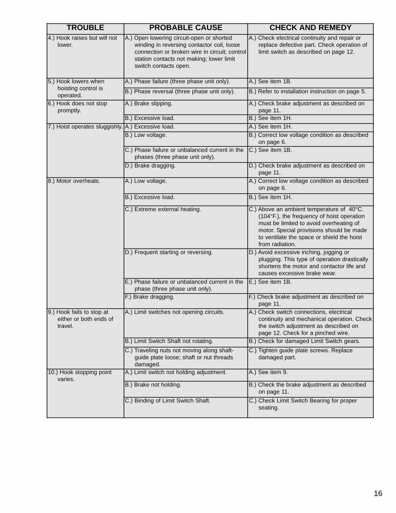
TROUBLE PROBABLE CAUSE CHECK AND REMEDY4.) Hook raises but will not
lower.A.) Open lowering circuit-open or shorted
winding in reversing contactor coil, loose connection or broken wire in circuit; controlstation contacts not making; lower limit switch contacts open.
A.) Check electrical continuity and repair or replace defective part. Check operation of limit switch as described on page 12.
5.) Hook lowers when hoisting control isoperated.
A.) Phase failure (three phase unit only). A.) See item 1B.
B.) Phase reversal (three phase unit only). B.) Refer to installation instruction on page 5.
6.) Hook does not stop promptly.
A.) Brake slipping. A.) Check brake adjustment as described on page 11.
B.) Excessive load. B.) See item 1H.7.) Hoist operates sluggishly. A.) Excessive load. A.) See item 1H.
B.) Low voltage. B.) Correct low voltage condition as described on page 6.
C.) Phase failure or unbalanced current in the phases (three phase unit only).
C.) See item 1B.
D.) Brake dragging. D.) Check brake adjustment as described on page 11.
8.) Motor overheats. A.) Low voltage. A.) Correct low voltage condition as described on page 6.
B.) Excessive load. B.) See item 1H.
C.) Extreme external heating. C.) Above an ambient temperature of 40°C. (104°F.), the frequency of hoist operation must be limited to avoid overheating of motor. Special provisions should be made to ventilate the space or shield the hoist from radiation.
D.) Frequent starting or reversing. D.) Avoid excessive inching, jogging or plugging. This type of operation drastically shortens the motor and contactor life and causes excessive brake wear.
E.) Phase failure or unbalanced current in the phase (three phase unit only).
E.) See item 1B.
F.) Brake dragging. F.) Check brake adjustment as described on page 11.
9.) Hook fails to stop at either or both ends of travel.
A.) Limit switches not opening circuits. A.) Check switch connections, electrical continuity and mechanical operation. Checkthe switch adjustment as described on page 12. Check for a pinched wire.
B.) Limit Switch Shaft not rotating. B.) Check for damaged Limit Switch gears.C.) Traveling nuts not moving along shaft-
guide plate loose; shaft or nut threads damaged.
C.) Tighten guide plate screws. Replacedamaged part.
10.) Hook stopping point varies.
A.) Limit switch not holding adjustment. A.) See item 9.
B.) Brake not holding. B.) Check the brake adjustment as described on page 11.
C.) Binding of Limit Switch Shaft. C.) Check Limit Switch Bearing for proper seating.

17
Figure 20. Typical Wiring Diagrams (Entertainment)Wiring Diagrams shown are representative. Consult diagram in hoist or furnished with unit.
WIR
ING
DIA
GR
AM
LOD
ESTA
R H
OIS
TM
OD
ELS
B-C
& F
TELE
MEC
HANI
QUE
CO
NTAC
TOR

18
Figure 20. Typical Wiring Diagrams (Entertainment)Wiring Diagrams shown are representative. Consult diagram in hoist or furnished with unit.
WIR
ING
DIA
GR
AM
LOD
ESTA
R H
OIS
TM
OD
ELS
J, J
J, L
, LL,
R &
RR
DUAL
VOLT
AGE
3 PH
ASE
TELE
MEC
HANI
QUE
CO
NTAC
TOR

Figure 20. Typical Wiring Diagrams (Direct Control)Wiring Diagrams shown are representative. Consult diagram in hoist or furnished with unit.
19
WIR
ING
DIA
GRA
MLO
DEST
AR H
OIS
TM
OD
ELS
B-C
& F
220/
415-
3-50
, 230
/460
-3-6
0DI
RECT
CO
NTRO
LUN
IT

Figure 20. Typical Wiring Diagrams (Direct Control)Wiring Diagrams shown are representative. Consult diagram in hoist or furnished with unit.
20
WIR
ING
DIA
GRA
MLO
DEST
AR H
OIS
TM
OD
ELS
J, J
J,L,
LL, R
& R
R22
0/41
5-3-
50, 2
30/4
60-3
-60
DIRE
CT C
ONT
ROL
UNIT

ASSEMBLY INSTRUCTIONS
SWIVEL HOOK SUSPENSIONModels R & RR.Assemble the dead end bolt and block through the suspen-sion adapter as shown in Figure 21.
Figure 21. Swivel Hook Suspension
INSTRUCTIONS FOR ASSEMBLING UPPER SUSPENSION TO HOIST-DOUBLE REEVED CHAIN MODELS
Place the suspension assembly into the recess provided onthe hoist. The dead end block should project through the bottom of the hoist with the pin hole and slot aligned to theunderside of the hoist as shown in the Figure 8 pg. 4. Ifthese are not aligned as shown, lift the head of the bolt fromthe hex recess in the adapter and turn the bolt and block assembly and reseat the bolt head to obtain proper align-ment. DO NOT change the position of the dead end block onthe bolt to attain this alignment.
Check the postion of the pin hole in the dead end block tomake sure that it has not been disturbed from its factory set-tings. The distance from the top of the pin hole to the bottomof the hoist should not exceed 7/16” (11mm) for Models R &RR. If the distance is not correct, adjust the position of thedead end block to obtain the proper distance. CAUTION: DONOT apply oil or any other lubricant to the threads of thesuspension adapter screws. Such lubricant will significantlyaffect the frictional characteristics and may damage thescrew or nut if the screw is tightened to the recommendedseating torques.
Now, insert the screws, supplied with the assembly, throughthe holes in the suspension adapter and thread these intothe self locking nut enclosed in the hoist. The screws willturn freely into the nut until the last 1/4” (6.35mm) of travelduring which the resistance of the nut locking collar will beencountered. Security tighten the screws to the recommend-ed seating torque specified in Table 9, using a 12 point socket (½” socket) which fits the head of the screw.
The dead end of the load chain is temporarily positioned (afew links from the end) by a wire clip. DO NOT remove thisclip before attaching the chain to the dead end block. Referto Figure 7, page 4 and the tag attached to the load chain onthe hoist.
Models B, C, F, J, L & LLINSTRUCTIONS FOR ASSEMBLING UPPER HOOK SUSPENSION TO HOIST-SINGLE CHAIN MODELS
Place the suspension assembly into the recess on the top ofthe hoist so that the adapter body follows the contour of thehoist. CAUTION: DO NOT apply oil or any other lubricant tothe threads of the suspension adapter screws. Such lubri-cant will significantly affect the frictional characteristics andmay damage the screw or nut if the screw is tightened to therecommended seating torques. Insert the screws, suppliedwith this assembly, through the holes in the adapter andthread these into the self locking nuts enclosed in the hoist.The screws will turn freely into the nuts until the last 1/4”(6.35mm) of travel during which the resistance of the nutlocking collar will be encountered. Securely tighten thescrews to the recommended seating torque specified inTable 9, using a 12 point socket (½” 13mm) which fits thehead of the screw.
WWAARRNNIINNGGThe suspension screws are special high strength screwsand under no circumstances should screws other thanthese be used to attach the supsension to the hoist. If otherthan the suppled, high strength screws are used, they maybreak and allow the hoist to fall from the support and thismay result in an accident that could cause injury and/orproperty damage.
!!
SCREW SIZE RECOMMENDED SEATING TORQUE
3/8-16 UNC-3A40.7 TO 61.0 Nm.(30 TO 45 LB. FT.)
1/2-20 UNF-3A 54.2 TO 108.5 Nm.(40 TO 80 LB. FT.)
Table 9. Recommended Seating Torque For SuspensionAdapter Screws
5 3/16”(132mm)
Models R & RR
Underside of BoltHead
Dead End Bolt
Dead End Block
CCAAUUTTIIOONNUSE OF IMPACT TOOLS (ELECTRIC OR PNEUMATIC)MAY CAUSE PREMATURE FAILURE OF ATTACHINGHARDWARE.
!!
21

GEARINGModels LL & RR have a special Liftwheel Gear (627-303)and Intermediate Pinion (627-325).
If the gear train in these hoists is disassembled, the followingsteps must be observed in order to properly orient the threeparts when reassembling:
1. Assemble liftwheel gear to liftwheel.
NOTE: These parts have their splines keyed in such a way that they will go together only one way. See Figure 20.
Figure 22. Non-Circular Gearing
2. To install the intermediate pinion, align the arrows that are stamped on the pinion and liftwheel gear so they point toward each other.
3. Check operation of gear train by rotating the pinion four (4) complete revolutions; liftwheel gear will turn one (1) complete revolution and the arrows will again be aligned as shown. If the arrows do not align or there is binding between the gear teeth, repeat the above steps.
4. For gearing lubrication instruction, see page 16.
FASTENERSModels B, C & F tighten motor housing cover screws (627-108) to where they have a minimum breakaway torque of5.423 Nm (48 pound inch) and the brake attaching screws(627-253) have a 5.649 Nm (50 pound inch) minimum break-away torque.
Models J, L, R, LL & RR tighten limit switch bracket attach-ing screws (627-220), motor end bell attaching screws (627-411), brake attaching screws (627-253) and hexagonal brakestud (627-265) to where they have a minimum breakawaytorque of 5.649 Nm (50 pound inch). The liftwheel gear nut(627-305) should be tighten to a seating torque of 115.245Nm (85 pound feet).
LOWER HOOK BLOCK PINWhen removing or installing the lower hook pin (627-764),care must be taken so as to prevent damaging the pinand/or hook block. These pins are tapered groove pins andas a result, they can only be removed in one direction. Toremove the pin, a V-Block, drift and hammer (or slow actingpress) are required. The drift should be the same diameteras the pin (5/16” diameter (7.94mm) for Models B, C & Fand 3/8” (9.52mm) diameter for Models J, L, R, LL & RR,and it should be placed on the small end of the pin. Thesmall end of the pin is the end opposite the end on which the3 grooves are visible. Place the hook block in the V-Blockand drive the pin out using the drift and a hammer or slowacting press.
To re-install the pin, the parts must be arranged the same asthey were when the pin was removed. To do this, use thesmall end of the pin as a gage. First check the holes in thehook block body and determine which hole is the largest.Place the hook body in the V-Block with the larger hole ontop. Next, check each end of the hole in the lower hookchain block (627-775) and determine which end is thelargest. Place the chain in the slot of the chain block andinsert the chain block, with the large hole on top, into thehook block body. Align the holes in the hook block body withthe hole in the chain block and insert the small end of the pinin the hole. Push the pin in by hande until it stops and thenuse a hammer or slow acting press to drive the pin into posi-tion so that the end of the pin is flush with the outside suraceof the hook block body.
22
WWAARRNNIINNGGUse of improper lower hook chain block pin as well asimproper installation of the pin can cause the pin to breakand allow the load to fall.
TTOO AAVVOOIIDD IINNJJUURRYY AANNDD PPRROOPPEERRTTYY DDAAMMAAGGEE::Use only CM supplied, special high strength lower hookchain block pin to attach the chain to the lower hook blockand install the pin as directed above.
!!IntermediatePinion 627-325
Liftwheel Gear627-303
Arrows Must BeAligned As Shown
Liftwheel627-302
Missing Tooth SpaceIn Liftwheel GearSpline
Missing Tooth InLiftwheel Spline
CA
UTI
ON
AT A
SSEM
BLY
AR
RO
WS
ON
GEA
R &
PIN
ION
MU
STLI
NE
UP

23
REMOVAL AND INSTALLATION OFLOAD CHAIN
USE ONLY CM DIN OR STAR ( ) GRADE LOAD CHAINAND CM REPLACEMENT PARTS. USE OF OTHER CHAINAND PARTS MAY BE DANGEROUS AND VOIDS FACTORY WARRANTY.
Hoist load chain can be installed by any one ofseveral methods.
The first method is recommended when replacing severelyworn load chain and requires disassembling the hoist.Method 2 does not require hoist disassembly, where asMethod 3 requires only partial disassembly.Method #1
a) Disconnect hoist from power supply.b) Remove back frame cover and disengage the limit
switch guide plate from the traveling nuts, see page 12 or 13.
c) Detach loose end of load chain from hoist frame, seeFigure 7. Also on single reeved models, detach the lower hook block from the load chain (see pg. 22). On double reeved models R & RR unfasten the deadend side of load chain.
d) Continue to disassemble the hoist and inspect the liftwheel, chain guides, motor housing and gear housing which if worn or damaged may cause pre-mature failure of the new chain. Parts can be easily identified by referring to pages 25 thru 44.
e) If the liftwheel pockets, in particular the ends, are worn or scored, replace liftwheel. If chain guidesand housing are worn, cracked or damaged these parts should also be replaced.
f) Reassemble hoist with the new load chain inserted over the liftwheel. Position chain with the weld on upstanding links away from liftwheel and leave only one foot of chain hanging free on loose end side. On double reeved models, make certain that the new load chain is free of twists.
g) Attach the loose end link to chain and connect it to the hoist frame with the loose end screw, washer andlockwasher, see Figure 7. BE CERTAIN THERE IS NO TWIST.
h) For single reeved models, attach the hook block to load chain (see Page 23) and proceed to step K.
i) For double reeved models, run the hoist (UP) untilonly 914.4 mm (36” Inches) of chain remains on deadend side. This will minimize the chance of introducinga twist between hook block and hoist. Allow the chainto hang free to remove twists.
j) Using a wire as a starter, insert the chain, flat link first, into lower hook blook (upstanding links will haveweld toward sheave) and pull through. Insert last link into slot in dead end block making certain that no twist exists in the reeving at any point. Assemble dead end pin, washer and cotter pin as shown in Figure 7.
k) Adjust limit switches as describe in Table 6, page 13. If the new chain is longer than the old, check to be sure limit switch will allow for new length of lift. In the event maximum adjustment does not allow entire length of lift, check with CM® for modification ifnecessary.
Method #2Treat the old load chain in hoist as a “starter chain” and pro-ceed with Steps from Method #1, a, b, c and h thru k. If astarter chain is used, the loose end link (two links requiredfor double reeved models) can serve as a temporary cou-pling link to connect together the starter chain in the hoistand the new load chain to be installed. Then, under power,reeve the new load chain through the liftwheel area, replac-ing the starter chain in unit. Run enough chain through toattach loose end link to hoist frame.CAUTION: For double reeved models, be sure to disconnect one of the loose end links from the loadchain before attaching it to the hoist.
Method #3a) First proceed with Steps 1a, b & c from Method #1.b) Then, carefully run the load chain out of the hoist,c) Disconnect hoist from power supply.d) Remove the electric brake assembly.e) Rotate the brake hub by hand, at the same time
feeding the load chain into and through liftwheel areawith hoist upside down or using a wire to pull the loadchain up onto the liftwheel as explained in Method #1step 1f.
f) Refer to Method #1 steps g thru j above to complete the installation.
WWAARRNNIINNGGUUSSEE OOFF CCOOMMMMEERRIICCAALL OORR OOTTHHEERR
MMAANNUUFFAACCTTUURREERR’’SS CCHHAAIINN AANNDD PPAARRTTSS TTOORREEPPAAIIRR CCMM HHOOIISSTTSS MMAAYY CCAAUUSSEE LLOOAADD LLOOSSSS..
TTOO AAVVOOIIDD IINNJJUURRYY::Use only CM supplied replacement load chain and parts.Chain and parts may look alike, but CM chain and parts aremade of specific material or processed to achieve specificproperties.
!!
WWAARRNNIINNGGImproper installation (reeving) of the load chain can result ina dropped load.
TTOO AAVVOOIIDD IINNJJUURRYY//DDAAMMAAGGEE:: Verify use of proper size and type of hoist load chain for
specific hoist.Install load chain properly as indicated below.
!!
WWAARRNNIINNGGDo not allow hook block to hit hoist or allow load
chain to become taut between loose end screw andframe or else serious damage will result. If hook block
should inadvertently hit the hoist-the hoist frames,load chain and hook block should be inspected for
damage before further use.
!!

CUTTING CHAIN
CM®Load chain is hardened and it is difficult to cut. The fol-lowing methods are recommended when cutting a length ofnew chain from stock or cutting off worn chain.
1. Use a grinder and nick the link on both sides (Figure 21), then secure the link in a vise and break off with a hammer.
2. Use a 177.8 mm (7 inches) minimum diameter by 3.175 mm (1/8 inch) thick abrasive wheel (or type recommended by wheel supplier) that will clear adjacent links.
3. Use a bolt cutter (Figure 22) similar to the H.K. Porter No. 0590MTC with special cutter jaws forcutting hardened chain (25.4mm-1 inch) long cutting edge.
Figure 23. Cutting Chain by Nicking
Figure 24. Cutting Chain with a Bolt Cutter
NOTE: For additional information on inspection andtesting, refer to Code B30.16 “Overhead Hoists” obtaine-able from ASME Order Department, 22 Law Drive, Box2300, Fairfield, NJ 07007-2300, U.S.A.
The following information must accompany all correspondence orders for replacement parts:
1. Hoist Model Number from identification plate.2. Serial number of the hoist stamped below identification
plate.3. Voltage, phase, Hertz from the identification plate.4. Length of lift.5. Key number of part from parts list.6. Number of parts required.7. Part name from parts list.8. Part number from the parts list.
NOTE: When ordering replacement parts, it isrecommended that consideration be given to the need for also ordering such items as gaskets, fasteners, insulators, etc. These items may be damaged or lost during disassembly or just unfit for future use because of deterioration from age or service.
24
ORDERING INSTRUCTIONS
WWAARRNNIINNGGUsing “Commercial” or other manufacturer’s parts to repairthe CM Lodestar Hoists may cause load loss.
TTOO AAVVOOIIDD IINNJJUURRYY::Use only CM supplied replacement parts. Parts may lookalike but CM parts are made of specific materials or processed to achieve specific properties.
!!
WWAARRNNIINNGGCutting Chain Can Produce Flying Particles.
TTOO AAVVOOIIDD IINNJJUURRYY:: Wear Eye Protection. Provide A shield Over Chain to Prevent Flying Particles.
!!
WWAARRNNIINNGGTESTING
Before using, all altered, repaired or used hoists thathave not been operated for the previous 12 monthsshall be tested by the user for proper operation. Firsttest the unit without a load and then with a light load of22.7 kg. (50 pounds) times the number of load support-ing parts of load chain to be sure that the hoist oper-ates properly and that the brake holds the load whenthe control is released. Next test with a load of *125% ofrated capacity. In addition, hoists in which load sustain-ing parts have been replaced should be tested with*125% of rated capacity by or under the direction of anappointed person and written report prepared forrecord purposes. After this test, check that theProtector functions. If the Protector permits lifting aload in excess of 200% of rated metric load, it shouldbe replaced.
*If Protector prevents lifting of a load of 125% of ratedcapacity, reduce load to rated capacity and continue
test.
!!

ENTERTAINMENT/DIRECT CONTROL LODESTAR-HOIST FRAMEKey No. Part Name Models B, C & F
(Qty.)Models J, L R, LL & RR
(Qty.)627-101 Motor Housing Cover Gasket 27847 (1) Weatherproof
Units Only35841 (1) Weatherproof
Units Only627-102 Back Frame Cover Gasket 27848 (1) Weatherproof
Units Only35840 (1) Weatherproof
Units Only627-108 Motor Housing Cover Screw 987397 (2) 987553 (2)627-109 Motor Housing Cover Screw Lockwasher 982226 (2)
982251 (2) WeatherproofUnits Only
982226 (2)982251 (2) Weatherproof
Units Only627-110 Motor Housing Cover 27597 (1) 36009 (1)627-115 Motor Housing 27063 (1) 35073 (1)627-120 Gear Housing 27038 (1) 35627 (1)627-124 Gear Housing Gasket 27747 (1) 35707 (1)627-125 Back Frame 27618 (1) 35031 (1)627-130 Back Frame Cover 28009 (1) 36008 (1)627-131 Back Frame Cover Screw Lockwasher 982226 (3)
982251 (3) WeatherproofUnits Only
982226 (4)982251 (4) Weatherproof
Units Only627-132 Back Frame Cover Screw 87325 (3) 968752 (4)627-445 Capacity Label 27277 (¼ Ton), 27227 (½ Ton) 35200 (½ Ton), 35201 (1 Ton),
35202 (2 Ton)627-685 Series Label 27238 (1) 36840 (1)
25
627-108
627-109
627-445
627-110
627-101
627-115
627-120
627-124
627-125
627-102
627-130
627-685
627-131
627-132
LIMIT SWITCH
ELECTRIC BRAKE
VOLTAGE CHANGE BOARD
CONTACTOR
TRANSFORMER
DRIVE SHAFT AND PINION
INTERMEDIATE GEAR AND PINION
LIFTWHEEL GEAR
LIFTWHEEL AND BEARINGS
CHAIN GUIDES
ADAPTOR NUTS
ROTOR ASSEMBLY
STATOR ASSEMBLY
MODELS B, C & F
SEE PAGE 27

627-108
627-109
627-685
627-110
627-101
627-120
627-124
627-125
627-102
627-130
627-131
627-132
627-445
627-115
ROTOR/STATOR ASSEMBLY
VOLTAGE CHANGE BOARD
CONTACTOR
TRANSFORMER
LIFTWHEEL AND BEARINGS
CHAIN GUIDES
ADAPTOR NUT
DRIVE SHAFT AND PINION
INTERMEDIATE GEAR AND PINION
LIFTWHEEL GEAR
LIMIT SWITCH
ELECTRIC BRAKE
MODELS J, L, R, LL & RR
26
SEE PAGE 27

27
ENTERTAINMENT/DIRECT CONTROL LODESTAR ELECTRIC CHAIN HOIST PARTS LIST-MECHANICAL627-700 Swivel Hook Suspension; 627-710 Rigid Hook Suspension
ModelsKeyNumber Part Name
No.Req’d.
B, C & F J, L & LL R & RRPart Number
627-700 Swivel Hook Suspension (includes items 627-701 thru 627-706 for B , C & F,J, L& LLIncludes items 627-701 thru 627-706, 627-830 & 627-833 thru 627-836 for model RR ).
1 *2792(latch type hook)
*3661(latch type hook)
*3660(latch type hook)
627-701Upper Hook with LatchLatch Type 1 28689 35617 35616Upper Hook-Latchlok Type 28643 36678 36680
627-702 Suspension Adapter Screw (Special Alloy Steel) 2 27529 35588
627-703 Suspension Adapter 1 27703 35740 35741627-704 Upper Hook Washer for Swivel Hook Suspension 1 27786 45930 45918
627-705 Upper Hook Collar/Nut for Swivel Hook Suspension 1 27350 35042 35041
627-706 Upper Hook or Suspension Lug Pin-Special Alloy Steel-Specify whether for Swivel or Rigid Type Suspension
1 27805 983763 for Rigid Susp.983764 for SwivelSusp.
983761 Rigid Susp.983762 SwivelSusp
627-710 Rigid Hook Suspension (includes items 627-701, 627-702, 627-703,627-706 & 627-711 for models B, C & F, J, L & LL. Includes items627-701, 627-702, 627-703, 627-706, 672-711, 627-830 and 627-833thr 627-836 for model RR.
1*2788
(latch type hook)*3651
(latch type hook)*3658
(latch type hook)
627-711 Upper Hook or Suspension Lug Collar(for Rigid Hook or Lug Suspension) 1 27361 35459 35479
627-716 Latch Kit (specify no req’d) - 45661 45662 45663
627-700-Complete Swivel Hook Suspension
627-701
627-702
627-716
627-703
*627-830
627-705
627-706
627-704
*Latch Type Hook contact CM for part number of Lower Hook Assembly with Latchlok Type Hook.**With Latch Type Hook. If lower hook block assembly with Latchlok Type Hook is required. Contact CM.***Contact CM for Part Number of Latchlok Type Hook.
627-711
627-706
627-703
627-701
627-716627-702
627-702
627-710 Complete Rigid Hook Suspensions

28
627-222
627-231
627-220
627-220
627-231
627-220
627-220
627-125
ENTERTAINMENT LODESTAR ELECTRIC CHAIN HOIST PARTS LIST-CONTROL ENDModels
KeyNumber Part Name No.
Req’d.B, C & F J, L, LL, R & RR
Part Number627-220 Limit Switch Shaft & Gear Kit 1 27749 36656627-222 Limit Switch Kit 1 31631 31636627-231 Limit Switch Bracket Sub-Assembly 1 27502 36644
Entertainment Lodestar Models B, C & FLimit Switch
Entertainment LodestarModels J, L, LL, R & RR
Limit Switch

ENTERTAINMENT/DIRECT CONTROL LODESTAR ELECTRIC CHAIN HOIST PARTS LIST-CONTROL END
ModelsKeyNumber Part Name No.
Req’d.B, C & F J, L, LL, R & RR
Part Number
627-125 Back Frame 127618 (Includes
627-123 & 627 211)
35031
627-127 Back Frame Attaching Screw 3 982699 -627-127A BackFrame Attaching Screw L.W. 3 982226 -627-128 Back Frame Attaching Screw 2 - 982698 (13/4” Lg., 44.5mm)627-128A BackFrame Attaching Screw L.W. 2 - 940830627-129 Back Frame Attaching Screw 2 - 987322 (2” Lg., 50.8mm)627-129A BackFrame Attaching Screw L.W. 2 - 940830627-245 Back Frame Seal Screw 1 - 982623627-251 Brake Base Plate And Studs 1 28668 35643627-252 Brake Attaching Screw L.W. - 982226,
2 req’d.945851, 1 red’d.
627-253 Brake Attaching Screw - 982708, 2 req’d.
982709, 1 req’d.
627-254 Brake Intermediate Plate 1 27090 35069627-255 Brake Spring 2 27751
(color codedblue)
35716 (color coded yellow) for ModelsJ, L & R
35717 (color coded green) for Models LL &RR
627-256 Brake Field Sub-Assembly 1 28677 (Includes627-262)
35629
627-257 Brake Stud Nut 2 945840 945840627-258 Brake Coil Retainer Strap 1 57753 35704627-259 Brake Coil 1 51518 51511 for Models J,L & R
51512 for Models LL & RR627-260 Brake Armature Assembly 1 28678 35600 (Includes 627-262)
627-261 Brake Friction Disc 1 or 2 27677 35632
627-262 Brake Shading Coil 2 54831 35826
29
Part Number for Packaged LubricantsUsed in the Lodestar Electric Chain Hoists
(Refer to page 11 for Lubrication Instructions)
LubricantUsage
Type of Lubricant
Part Numbers andPackaged Quantity of
LubricantsHoist Gears Grease
(Special)28605 for ½ # Can28616 for 1# Can28617 for 4# Can
Spline on end ofDrive Shaft
Oil-GraphiteMixture
40628 for 1 pint Can
Load Chain Oil 28608 for 1 Pint Can28619 for 1 Gal Can
Limit Switch ShaftThreads
*Oil “3 in 1” or Light MachineOil-obtain locally
Lower HookThrust Bearing
*Oil Heavy Machine Oil-obtain locally
*These oils are not furnished by CM in Packaged Quantities.When ordering lubricants, specify the type of lubricant, part number and packages quantily required.Touch-up Paints for Lodestar Electric Chain Hoists:Hoist Order *(1) case (12-12 oz. Aerosol Cans) of Black Touch-up paints Part Number 84189.
*Touch-up paints are only available in case quantities.
NOTE: When painting Hoists, also order warning labels, identification labels, etc. that may be coated during painting.

30
Entertainment/Direct Control Lodestar Models B, C & F Brake
Entertainment/Direct Control Lodestar Models J, L, LL, R & RR Brake

EENNTTEERRTTAAIINNMMEENNTT//DDIIRREECCTT CCOONNTTRROOLL--LLOODDEESSTTAARR EELLEECCTTRRIICC CCHHAAIINN HHOOIISSTT--PPRROOTTEECCTTOORR KKIITT
KKeeyyNNuummbbeerr
PPaarrtt NNaammee NNoo.. RReeqq’’dd..
MMooddeellss
BB,,CC && FF JJ,, LL,, LLLL,, RR && RRRR
662277--112200 GGeeaarr HHoouussiinngg 11 2277003388 3355662277 ((IInncclluuddeess 662277--111199))662277--112222 GGeeaarr HHoouussiinngg AAttttaacchhiinngg SSccrreeww 44 2288883300 3355773333662277--112222AA GGeeaarr HHoouussiinngg AAttttaacchhiinngg SSccrreeww LL..WW.. 44 994400880022 994400883300662277--112244 GGeeaarr HHoouussiinngg GGaasskkeett 11 2277774477 3355770077662277--330033 LLiiffttwwhheeeell GGeeaarr 11 2277000099 ((5533 TTeeeetthh)) ffoorr MMooddeell BB && FF
2277001100 ((4477 TTeeeetthh)) ffoorr MMooddeell CC 3355000099 ((7799 TTeeeetthh)) ffoorr MMooddeellss JJ,, LL && RR,,3355663399 ((6600 TTeeeetthh)) ffoorr MMooddeellss LLLL && RRRR
662277--330044 LLiiffttwwhheeeell GGeeaarr SSnnaapp RRiinngg 11 2277776677 --662277--330055 LLiiffttwwhheeeell GGeeaatt NNuutt 11 -- 3355777733662277--330066 LLiiffttwwhheeeell GGeeaarr NNuutt WWaasshheerr 11 -- 998866227766662277--330077 LLiiffttwwhheeeell BBeeaarriinngg--GGeeaarr EEnndd 11 8888442299 8822000022662277--331100 DDrriivvee SShhaafftt aanndd PPiinniioonn SS..AA..
((IItteemmss 662277--331111 TThhrruu 662277--331155,,aass aapppplliiccaabbllee))
112277665533 ffoorr MMooddeell BB
2277665544 ffoorr MMooddeellss CC && FF3355668888 ffoorr MMooddeell JJ
3355668877 ffoorr MMooddeellss LL,, LLLL,, RR && RRRR
662277--331111 DDrriivvee SShhaafftt aanndd PPiinniioonn 11 2244664411 ffoorr MMooddeell BB2244664422 ffoorr MMooddeellss CC && FF
3355335577 ((1188 tteeeetthh)) ffoorr MMooddeell JJ3355335566 ((1122 tteeeetthh)) ffoorr MMooddeellss LL,, LLLL,, RR && RRRR
662277--331122 DDrriivvee SShhaafftt PPiinniioonn BBeeaarriinngg 11 8822000099 8833669911662277--331133 DDrriivvee SShhaafftt BBeeaarriinngg SSppaacceerr 11 2277771100 --662277--331144 BBrraakkee HHuubb 11 2277885511 ((2211//3322 LLgg..)) ffoorr MMooddeell BB
2277885522 ((11--11//88 LLgg..)) ffoorr MMooddeellss CC && FF3355774444
662277--331155 BBrraakkee HHuubb SSnnaapp RRiinngg 11 2277776666 3355776666662277--332211 IInntteerrmmeeddiiaattee GGeeaarr && PPiinniioonn
BBeeaarriinngg--OOuuttbbooaarrdd 11 8822000099 8888443377
662277--332222 LLiimmiitt SSwwiittcchh DDrriivvee PPiinniioonn 11 2277771122 --662277--332233 IInntteerrmmeeddiiaattee GGeeaarr SSnnaapp RRiinngg 11 2277776655 3355776633662277--332255 IInntteerrmmeeddiiaattee PPiinniioonn ((iinncclluuddeess IItteemm
662277--332222 ((IIff aapppplliiccaabbllee))11 2288662233 ((88 tteeeetthh)) ffoorr MMooddeellss BB && FF
2288662244 ((1144 tteeeetthh)) ffoorr MMooddeell CC 3355335511 ((1100 tteeeetthh)) ffoorr MMooddeellss JJ,, LL && RR3355442200 ((1155 tteeeetthh)) ffoorr MMooddeellss LLLL && RRRR
662277--332266 IInntteerrmmeeddiiaattee GGeeaarr aanndd PPiinniioonnBBeeaarriinngg--IInnbbooaarrdd
11 8888444400 OOrrddeerr ((11)) BBeeaarriinngg 8833667700 aanndd((11)) SShhaafftt AAddaapptteerr 2244335500
662277--332277 LLooddeessttaarr PPrrootteeccttoorr 11 2288669944 ffoorr MMooddeell BB,,2288669955 ffoorr MMooddeellss CC && FF
3366666688 ffoorr MMooddeell JJ,,3366667700 ffoorr MMooddeellss LL && RR
3366667711 ffoorr MMooddeellss LLLL && RRRR662277--332288 LLooddeessttaarr PPrrootteeccttoorr KKiitt ((IInncclluuddeess
iitteemmss 662277--112244,, 662277--332211,, 662277--332222,,662277--332233,, 662277--332255 && 662277--332277))
11 22887788 ffoorr MMooddeell BB,,22888800 ffoorr MMooddeellss CC && FF
33660022 ffoorr MMooddeell JJ,,33660033 ffoorr MMooddeellss LL && RR
33660044 ffoorr MMooddeellss LLLL && RRRR
31
Entertainment/Direct Control LodestarModels B, C & F
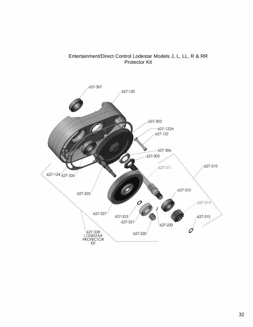
Entertainment/Direct Control Lodestar Models J, L, LL, R & RRProtector Kit
32

627-108
627-109
627-110
627-415
627-413
627-417
627-417
627-416
627-101
627-115
EENNTTEERRTTAAIINNMMEENNTT//DDIIRREECCTT CCOONNTTRROOLL--LLOODDEESSTTAARR EELLEECCTTRRIICC CCHHAAIINN HHOOIISSTT--MMOOTTOORR EENNDD
KKeeyyNNuummbbeerr
PPaarrtt NNaammee NNoo.. RReeqq’’dd..
MMooddeellss
BB,,CC && FF JJ,, LL,, LLLL,, RR && RRRR
PPaarrtt NNuummbbeerr662277--110011 GGeeaarr HHoouussiinngg GGaasskkeett 11 2277884477 WWeeaatthheerrpprrooooff UUnniittss OOnnllyy 3355884411 WWeeaatthheerrpprrooooff UUnniittss OOnnllyy662277--110088 MMoottoorr HHoouussiinngg CCoovveerr SSccrreeww -- 998877339977 ((22 RReeqq’’dd..)) 998877555533 ((22 RReeqq’’dd..))662277--110099 MMoottoorr HHoouussiinngg CCoovveerr SSccrreeww LLoocckk
WWaasshheerr-- 998822222266 ((22 RReeqq’’dd..))
998822225511 ((22 RReeqq’’dd..)) WWeeaatthheerrpprrooooffUUnniittss oonnllyy
998822222266 ((44 RReeqq’’dd..))998822225511 ((44 RReeqq’’dd..))WWeeaatthheerrpprrooooff UUnniittss
oonnllyy662277--111100 MMoottoorr HHoouussiinngg CCoovveerr 11 2277005599 3366007766662277--111155 MMoottoorr HHoouussiinngg 11 2277006633 3355007733662277--112244 GGeeaarr HHoouussiinngg GGaasskkeett 11 2277774477 3355770077662277--441111 MMoottoorr TThhrruu BBoollttss
44------ 8877337777 ffoorr MMooddeellss JJ,, LL && RR
8877333366 ffoorr MMooddeellss LLLL && RRRR
662277--441133 RRoottoorr && SShhaafftt AAsssseemmbbllyy 11 228866000044 FFoorr MMooddeell BB228866000000 FFoorr MMooddeellss CC && FF ******336677000022 ffoorr MMooddeellss JJ,, LL && RR
****** 336677000088 ffoorr MMooddeellss LLLL && RRRR662277--441155 SSttaattoorr 11 228877000066 FFoorr MMooddeell BB228877000011 FFoorr MMooddeellss CC && FF
662277--441166 MMoottoorr SShhaafftt BBeeaarriinngg ((IInnbbooaarrdd)) 11 8822000033 8822000044662277--441177 MMoottoorr SShhaafftt IInnbbooaarrdd BBeeaarriinngg
SSnnaapprriinngg22 2277779900 3355776644
****** 33//44 MMoottoorr IInncclluuddeess SSttaattoorr,, RRoottoorr && SShhaafftt AAsssseemmbbllyy,, EEnndd BBeellll && AAttttaacchhiinngg SSccrreewwss aasssseemmbblleedd ccoommpplleettee..IInnddiivviidduuaall RRoottoorr aanndd SShhaafftt AAsssseemmbbllyy && SSttaattoorrss ffoorr RReeppaaiirrss nnoott yyeett aavvaaiillaabbllee..
Models B, C & FMotor End
33

34
Models J, L, LL, R & RRMotor End

627-760COMPLETE SINGLE REEVED
LOWER HOOK BLOCK ASSEMBLY
627-760
627-774
627-776
627-771
627-716
627-763
627-777
627-772
627-764
*Latch Type Hook contact CM for part number of Lower Hook Assembly with Latchlok Type Hook.
**With Latch Type Hook. If lower hook block assembly with Latchlok Type Hook is required. Contact CM.
***Contact CM for Part Number of Latchlok Type Hook.
627-860COMPLETE DOUBLE REEVED
LOWER HOOK BLOCK ASSEMBLY
ENTERTAINMENT/DIRECT CONTROL LODESTAR ELECTRIC CHAIN HOIST PARTS LIST-MECHANICAL627-760 Single Reeved Complete Lower Hook Block Assembly627-860 Double Reeved Complete Lower Hook Block Assembly
ModelsKeyNumber
Part Name No.Req’d.
B, C & F J, L & LL R & RR
Part Number
627-716 Latch Kit (specify no. req’d) - 45661 45662 45663627-760 Lower Hook Block Assembly 1 **28683 **35651 35621627-763 Lower Hook Body 1 45401 35370 -627-764 Lower Hook Chain Block Pin 1 45943 35790 -627-770 Lower Hook Block Assembly 1 - - *35645
627-771Lower Hook with Latch:Latch Type Hook 1 28686 35611 35612Latchlok Type Hook 1 28604 28604 36681
627-772 Lower Hook Thrust Bearing 1 88485 88485 88505627-773 Lower Hook Collar 1 - - 35369627-774 Lower Hook Pin 1 983772 983772 45946627-775 Lower Hook Chain Block 1 28007 35026 -627-776 Lower Hook Nut 1 982526 982526 -627-777 Lower Hook Block Washer 1 945921 945921 -627-833 Dead End Block 1 - - 35418627-834 Dead End Pin 1 - - 82314627-835 Dead End Pin Cotter Pin 1 - - 988330627-836 Dead End Pin Washer 1 - - 987877627-837 Contact Block 1 - - 36764627-860 Lower Hook Block Assembly-Complete 1 - - **35621627-861 Hook Block Sheave 1 - - 35010627-862 Hook Block Sheave Bearing 2 - - 83674627-863 Hook Block (Order in Pairs) 2 - - 35034627-864 Hook Block Screw-Long 2 - - 982374627-865 Hook Block Screw-Short 1 - - 982370627-866 Hook Block Screw L.W. 3 - - 940830627-867 Hook Block Screw Nut 3 - - 982445
627-775
35

V1 EN
TERTA
INM
ENT-M
OD
ELS B, C
& F
Key No.D
escriptio
nQ
ty.Part N
o.
627-602Contactor Bracket Plate Stud
327836
627-604Contactor Bracket Plate Stud Lockw
asher3
982226627-605
Contactor Bracket Plate Stud Nut
3982514
627-1000In
sulated
Brake C
oil Term
inal
2983197
627-1001Contactor Bracket
131633
627-1002Spare Fuse Clam
p1
951951Fuse (160m
A)-Sp
ecify Qu
antity
-27675
627-1003Spare Fuse Label
127674
627-1003AG
rou
nd
Symb
ol Lab
el1
20940
627-1004Fu
se Clam
p A
ttachin
g Screw
1982574
Fuse Clamp A
ttaching Screw Lockw
asher1
987844
627-1005
Reversin
g C
on
atactor (115v C
oil)
(48 v Co
il)(24v C
oil)
124799
124797
128860
627-1006C
on
tactor A
ttachin
g Screw
2982718
627-1007Transform
er w/fusing
(115v sec)
(Fuses n
ot in
clud
ed) (48v sec)(24v sec)
128294
128295
128296
627-1008Tran
sform
er Mo
un
ting
Screw2
982683627-1009
Contactor/Transformer W
iring Harness
127602
627-1010Line Connector-Specify Q
ty.-
982158627-1011
Motor W
iring Harness (1 Speed)
127603
627-1012B
oard
Attach
ing
Screw1
987862627-1013
Vo
ltage C
han
ge B
oard
(1 Speed
)1
27672627-1014
Vo
ltage C
han
ge B
oard
Insu
lator
127685
627-1016W
arning Tag1
81704627-1017
Instru
ction
Tag1
28271627-1018
Pow
er Co
rd1
31701627-1019
Control Cord Assem
bly-Entertainment
131703
627-1020H
oist I.D
. Plate1
Co
ntact
Factory
627-1021
Vo
ltage Lab
el-Mo
del B
127698
Mo
del C
127699
Mo
del F
127696
627-1022Ju
mp
ers:W
1 “UP” Lim
it Switch
Jum
per
127613
W2 “D
ow
n” Lim
it Switch
Jum
per
127614
R10 Tran
sform
er Jum
per
127609
R13 Tran
sform
er Jum
per
127610
G-Y
Ground Jum
per1
27686Contactor Coil Jum
per1
27627
3637

3938
V2 EN
TERTA
INM
ENT-M
OD
ELS J, L, R, LL &
RR
Key No.D
escriptio
nQ
ty.Part N
o.
627-599Contactor Bracket M
tg. Screw3
983643627-1000
Insu
lated B
rake Co
il Termin
al2
983197627-1001
Contactor Bracket1
31635
627-1002Spare Fuse Clam
p1
951951Fuse (160m
A)-Sp
ecify Qu
antity
-27675
627-1003Spare Fuse Label
127674
627-1003AG
rou
nd
Symb
ol Lab
el1
20940
627-1004Fu
se Clam
p A
ttachin
g Screw
1982574
Fuse Clamp A
ttaching Screw Lockw
asher1
987844
627-1005
Reversin
g C
on
atactor (115v C
oil)
(48 v Co
il)(24v C
oil)
124799
124797
128860
627-1006C
on
tactor A
ttachin
g Screw
1982718
627-1007Transform
er w/fusing
(115v sec)
(Fuses n
ot in
clud
ed) (48v sec)(24v sec)
128294
128295
128296
627-1008Tran
sform
er Mo
un
ting
Screw2
982683627-1009
Contactor/Transformer W
iring Harness
135613
627-1010Line Connector-Specify Q
ty.-
982158627-1011
Motor W
iring Harness (1 Speed)
135615
627-1012B
oard
Attach
ing
Screw1
987862627-1013
Vo
ltage C
han
ge B
oard
(1 Speed
)1
27672627-1014
Vo
ltage C
han
ge B
oard
Insu
lator
127685
627-1016W
arning Tag1
81704627-1017
Instru
ction
Tag1
28271627-1018
Pow
er Co
rd1
31701627-1019
Control Cord Assem
bly-Entertainment
131704
627-1020H
oist I.D
. Plate1
Co
ntact
Factory
627-1021
Vo
ltage Lab
el-Mo
del J
127690
Mo
del L
127687
Mo
del R
127691
Mo
del LL
127692
Mo
del R
R1
27693627-1022
Jum
pers:
W1 “U
P” Limit Sw
itch Ju
mp
er1
35661W
2 “Do
wn
” Limit Sw
itch Ju
mp
er1
35662R
10 Transfo
rmer Ju
mp
er1
35638R
13 Transfo
rmer Ju
mp
er1
35641G
-Y G
round Jumper
127686
Contactor Coil Jumper
127627

V1 DIRECT CONTROL - MODELS B, C & FKey No. Description Qty. Part No.624-163 Loose End Chain (8-Links) 1 85832624-164 Loose End Block 1 24015
624-165Loose End Chain Pin &Load Chain Pin 1 C328
624-166 Stop Block 1 24785627-1000 Insulated Brake Coil Terminal 2 983197627-1003A Ground Symbol Label 1 20940627-1017 Instruction Tag 1 28271627-1018 Power Cord Assembly 1 27637627-1020 Hoist I.D. Plate 1 Contact
Factory627-1023 Grommet Plug 1 27891
627-1024 Brake Jumper Harness 1 27715627-1025 Terminal Strip 1 27700
627-1026Terminal Strip Mounting Screw 2 982718Terminal Strip Mounting Plate Lockwasher 2 987929
627-1027 Bracket Spacer 2 27709627-1028 Terminal Strip Mounting Plate 1 27704
627-1029Bracket Mounting Screw 2 987395Bracket Mounting Screw Lockwasher 2 982226
40

41
V2 DIRECT CONTROL - MODELS J, L, R, LL & RRKey No. Description Qty. Part No.624-163 Loose End Chain (8-Links) 1 85832624-164 Loose End Block 1 24016
624-165Loose End Chain Pin &Load Chain Pin 1 C348
624-166 Stop Block 1 24786627-599 Mounting Plate Screws 2 983643627-1000 Insulated Brake Coil Terminal 2 983197627-1003A Ground Symbol Label 1 20940627-1017 Instruction Tag 1 28271627-1018 Power Cord Assembly 1 31711627-1020 Hoist I.D. Plate 1 Contact
Factory627-1023 Grommet Plug 1 27891
627-1024 Brake Jumper Harness 1 35637627-1025 Terminal Strip 1 27700
627-1026Terminal Strip Mounting Screw 2 982718Terminal Strip Mounting PlateLockwasher
2 987929
627-1028 Terminal Strip Mounting Plate 1 27704

42
GEARINGKey No. Description Qty. Part No.627-115 Motor Housing 1 27063627-117 Suspension Adapter Nut 2 927755627-118 Chain Guide 2 27008627-302 LiftWheel 1 27360627-307 Lift Wheel Bearing (Gear End) 1 88429627-308 Lift Wheel Bearing (Motor End) 1 88429627-740 Loose End Screw 1 927764
627-741 Loose End Screw Lockwasher 1 982226627-742 Loose End Screw Washer 1 954802627-743 Loose End Link 1 27351627-750 Load Chain - 85994627-1030 Dead End Block Hole Plug 1 27223
V1 ENTERTAINMENT/DIRECT CONTROLMODELS B, C & F

43
GEARINGKey No. Description Qty. Part No.
627-112 Suspension Adapter 2 35066627-115 Motor Housing 1 35073627-117 Suspension Adapter Nut 2 935791627-118 Chain Guide 2 35018627-302 LiftWheel 1 35421627-307 Lift Wheel Bearing (Gear End) 1 82002627-308 Lift Wheel Bearing (Motor End) 1 83669627-740 Loose End Screw 1 987210
627-741 Loose End Screw Lockwasher 1 945851627-742 Loose End Screw Washer 1 954807627-743 Loose End Link 1 35367627-750 Load Chain - 85949627-833 Dead End Block 1 35418627-834 Dead End Pin (Models R & RR) 1 82314627-835 Dead End Pin Cotter Pin (Models R & RR) 1 988330627-836 Dead End Pin Washer (Models R & RR) 1 987877627-837 Contact Block (Models R & RR) 1 36764627-1030 Dead End Block Hole Plug (Models J, L & LL) 1 35291
V2 ENTERTAINMENT/DIRECT CONTROLMODELS J, L, R, LL & RR

44
NOTES

45
NOTES

46
NOTES