
Operating Instructions • Warning Information • Parts Break ...mytoolservice.com/man/5008.pdf ·...
16
5008 Rev. 02/06/06 Operating Instructions • Warning Information • Parts Breadown Capacity...................................... 90˚ 8" (200mm) 8" x " (200 x 280mm) 2.4" x 3.8" (60 x 350mm) Capacity...................................... 45˚ 5.5" (40mm) 5.5" x 6" (40 x 55mm) Blade Size ............." x 0.035"x07" (27 x 0.9 x 2720mm) Blade Speed ..... 86/28/75/244 FPM (26/39/53/74 MPM) Motor ...............5HP Phase, 8 Amp, 732 RPM Shipping 62.5" x 3.3" x 45" Measurement .. (588 x 795 x 43mm) Net Weight .................... 57lbs (235kg) Gross Weight............. 594 lbs (270kgs) SPECIFICATIONS ALWAYS READ INSTRUCTIONS BEFORE USING POWER TOOLS ALWAYS WEAR SAFETY GOGGLES WEAR HEARING PROTECTION 5008 8"X 14" HORIZONTAL BAND SAW 5008_OpMan020606.indd 1 2/6/06 4:50:50 PM
Transcript of Operating Instructions • Warning Information • Parts Break ...mytoolservice.com/man/5008.pdf ·...

5008 � Rev.02/06/06
Operating Instructions • Warning Information • Parts Breakdown
Capacity......................................90˚
8"(200mm)
8"x��"(200x280mm)
2.4"x�3.8"(60x350mm)
Capacity......................................45˚
5.5"(�40mm)
5.5"x6"(�40x�55mm)
BladeSize.............�"x0.035"x�07"
(27x0.9x2720mm)
BladeSpeed..... 86/�28/�75/244FPM
(26/39/53/74MPM)Motor..............�.5HP�Phase,�8Amp, �732RPM
Shipping 62.5"x3�.3"x45"Measurement.. (�588x795x��43mm)
NetWeight....................5�7lbs(235kg)
GrossWeight............. 594lbs(270kgs)
SPECIFICATIONS
AlwAys reAd instructions before using power tools
AlwAys weAr sAfety goggles
weAr heAring protection
5008 8"x 14"
Horizontal Band Saw
5008_OpMan020606.indd 1 2/6/06 4:50:50 PM

5008 2 Rev.02/06/06
This Instruction Manual Contains Important Safety Information.
READ THIS INSTRUCTION MANUAL CAREFULLY AND UNDERSTAND ALL INFORMATION BEFORE OPERATING THIS TOOL.�. KEEPGUARDSINPLACEandinworkingorder.
2. REMOVEADJUSTINGKEYSANDWRENCHES. Alwaysensurekeysandadjustingwrenchesare removedfromtoolbeforeturningiton.
3. KEEPWORKAREACLEAN.Clutteredareasand benchesinviteaccidents.
4. DONOTUSEINDANGEROUSENVIRONMENT. Donotusepowertoolsindamporwetlocations,or exposethemtorain.Keepworkareawelllighted.
5. KEEPCHILDRENAWAY.Allvisitorsshouldbekeptsafe distancefromworkarea.
6. MAKEWORKSHOPCHILDPROOFwithpadlocks, masterswitches,orbyremovingstarterkeys.
7. DONOTFORCETOOL.Itwilldothejobbetterand saferattherateforwhichitwasdesigned.
8. USERIGHTTOOL.Donotforcetoolorattachmentto doajobforwhichitwasnotdesigned.
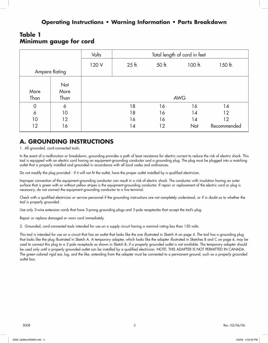
9. USEPROPEREXTENSIONCORD.Makesureyour extensioncordisingoodcondition.Whenusingan extensioncord,besuretouseoneheavyenoughto carrythecurrentyourproductwilldraw.An undersizedcordwillcauseadropinlinevoltage resultinginlossofpowerandoverheating.Table� showsthecorrectsizecordtousedependingoncord lengthandnameplateampererating.Ifindoubt,use thenextheaviergauge.Thesmallerthegaugenumber, theheavierthecord.
�0. WEARPROPERAPPAREL.Donotwearlooseclothing, gloves,neckties,rings,bracelets,orotherjewelry whichmaygetcaughtinmovingparts.Nonslip footwearisrecommended.Wearprotectivehair coveringtocontainlonghair.
��. ALWAYSUSESAFETYGLASSES.Usefaceordust maskifcuttingoperationisdusty.Remember,everyday eyeglassesonlyhaveimpactresistantlenses,theyare NOTsafetyglasses.
�2. SECUREWORK.Useclampsoravisetoholdwork whenpractical.Itissaferthanusingyourhandandit freesbothhandstooperatetool.
�3. DONOTOVERREACH.Keepproperfootingand balanceatalltimes.
�4. MAINTAINTOOLSWITHCARE.Keeptoolssharpand cleanforbestandsafestperformance.Follow instructionsforlubricatingandchangingaccessories.
�5. DISCONNECTTOOLSfrompowersourcebefore servicing,orwhenchangingaccessories,suchas blades,bits,cutters,etc.
�6. REDUCETHERISKOFUNINTENTIONALSTARTING. MakesureswitchisinOFFpositionbeforepluggingin powercord.
�7. USERECOMMENDEDACCESSORIES.Consultthe owner’smanualforrecommendedaccessories.Theuse ofimproperaccessoriesmayincreaseriskofinjuryto persons.
�8. NEVERSTANDONTOOLSeriousinjurycouldresult ifthetoolistippedorifthecuttingtoolis unintentionallycontacted.
�9. ALWAYSCHECKFORDAMAGEDPARTS.Before eachuseofthetool,aguardorotherpartthatis damagedshouldbecarefullycheckedtodetermine thatitwilloperateproperlyandperformitsintended function-checkforalignmentofmovingparts,binding ofmovingparts,breakageofparts,mounting,andany otherconditionsthatmayaffectitsoperation. A guard or other part that is damaged should be properly repaired or replaced.
20. DIRECTIONOFFEED.Feedworkintoabladeor cutteragainstthedirectionofrotationofthebladeor cutteronly.
2�. NEVERLEAVETOOLUNATTENDED WHILERUNNING.TURNPOWEROFF. Donotleavetooluntilitcomestoacompletestop.
For Your Own Safety Read Instruction Manual Before Operating This Tool
5008_OpMan020606.indd 2 2/6/06 4:50:56 PM
5008 3 Rev.02/06/06
Operating Instructions • Warning Information • Parts Breakdown
A. GROUNDING INSTRUCTIONS�. Allgrounded,cord-connectedtools:
Intheeventofamalfunctionorbreakdown,groundingprovidesapathofleastresistanceforelectriccurrenttoreducetheriskofelectricshock.Thistoolisequippedwithanelectriccordhavinganequipment-groundingconductorandagroundingplug.Theplugmustbepluggedintoamatchingoutletthatisproperlyinstalledandgroundedinaccordancewithalllocalcodesandordinances.
Donotmodifytheplugprovided-ifitwillnotfittheoutlet,havetheproperoutletinstalledbyaqualifiedelectrician.
Improperconnectionoftheequipment-groundingconductorcanresultinariskofelectricshock.Theconductorwithinsulationhavinganoutersurfacethatisgreenwithorwithoutyellowstripesistheequipment-groundingconductor.Ifrepairorreplacementoftheelectriccordorplugisnecessary,donotconnecttheequipment-groundingconductortoaliveterminal.
Checkwithaqualifiedelectricianorservicepersonnelifthegroundinginstructionsarenotcompletelyunderstood,orifindoubtastowhetherthetoolisproperlygrounded.
Useonly3-wireextensioncordsthathave3-pronggroundingplugsand3-polereceptaclesthatacceptthetool’splug.
Repairorreplacedamagedorworncordimmediately.
2. Grounded,cord-connectedtoolsintendedforuseonasupplycircuithavinganominalratinglessthan�50volts:
ThistoolisintendedforuseonacircuitthathasanoutletthatlooksliketheoneillustratedinSketchAonpage4.ThetoolhasagroundingplugthatlooksliketheplugillustratedinSketchA.Atemporaryadapter,whichlooksliketheadapterillustratedinSketchesBandConpage4,maybeusedtoconnectthisplugtoa2-polereceptacleasshowninSketchB,ifaproperlygroundedoutletisnotavailable.Thetemporaryadaptershouldbeusedonlyuntilaproperlygroundedoutletcanbeinstalledbyaqualifiedelectrician.NOTE:THISADAPTERISNOTPERMITTEDINCANADA.Thegreen-coloredrigidear,lug,andthelike,extendingfromtheadaptermustbeconnectedtoapermanentground,suchasaproperlygroundedoutletbox.
Table 1Minimum gauge for cord
Volts Totallengthofcordinfeet
�20V 25ft. 50ft. �00ft. �50ft. AmpereRating Not More More Than Than AWG
0 6 �8 �6 �6 �4 6 �0 �8 �6 �4 �2 �0 �2 �6 �6 �4 �2 �2 �6 �4 �2 Not Recommended
5008_OpMan020606.indd 3 2/6/06 4:50:56 PM

5008 4 Rev.02/06/06
Operating Instructions • Warning Information • Parts Breakdown
Grounding Methods
Electrical Schematic – Single Phase
5008_OpMan020606.indd 4 2/6/06 4:50:59 PM

5008 5 Rev.02/06/06
General Safety Information�. ReadtheInstructionmanualbeforeoperatingthemachine.
2. Ifyouarenotthoroughlyfamiliarwiththeoperationofhorizontal bandsaws,obtainadvicefromyoursupervisor,instructororother qualifiedperson.
3. Removetie,rings,watchandotherjewelry,androllupsleeves.
4. Alwayswearsafetyglassesorafaceshield.
5. Makesurewiringcodesandrecommendedelectricalconnection instructionsarefollowedandthatmachineisproperlygrounded.
6. Makealladjustmentswiththepowershut-off.
7. Adjustandpositionthebladeguidebeforestartcutting.
8. Makesurethatbladetensionisproperlyadjustedbeforestart cutting.
9. Stopthesawbeforeputtingaworkpieceinthevise.
�0.Alwayskeephandsandfingersawayfromthebladewhenthe machineisrunning.
��.Stopthemachinebeforeremovingchips.
�2.Alwayshavestockfirmlyclampedinvise,beforestartcutting.
�3.Disconnectmachinefrompowersourcewhenmakingrepairs.
�4.Beforeleavingthemachine,makesuretheworkareaisclean.
Operating Instructions�. CheckCoolant:Lowcoolantlevelcausesfoamingandhighblade temperatures.Dirtyorweakcoolantcanclogpump,causes crookedcuts,lowcuttingrateandpermanentbladefailure.Dirty coolantcausesthegrowthofbacteriawithensuingskinirritation.
2. Keepviseslidescleanandoiled.
3. Cleanchipsfrombladewheelsandtheareasaroundwheels.
4. SawGuide:Keepsawguidesproperlyadjusted.Looseguideswill affectcuttingaccuracy.
5. SawBlade:Ensurethatthesawbladeissharp.
6. BladeSpeed:Ensurebladespeedissetcorrectlyforworkpiece materialandshape.
7. CheckBladeTension:Particularlyafterinitialcutswithanewblade.
Blade Selection�. Neveruseabladesocoarsethatlessthan3teethareengaged intheworkpieceatanytime.(Toofewteethwillcauseteethto stripout.)
2. Neveruseabladefinerthanrequiredtoobtainasatisfactory surfacefinishorsatisfactoryflatness.(Toomanyteethengaged intheworkpiecewillpreventattainmentofasatisfactorysawing rate;frequentlycauseprematurebladewear;frequentlyproduce “dished”cutsorthecutsareneithersquarenorparallel.)
3. Thechartwhichfollowsisnotexpectedtobeexactlycorrectforall cases.Itisintendedasageneralguidetogoodsawingpractices Yourbladesupplierorthequalifiedengineersshouldbeyourmost reliablesourceofcorrectinformationforoperationaldetailsofsaw bladesandtheiruse.
THE SELECTION OF SAWBLADES
<3mm >5mm >50mm >�00mm >�50mm >200mm
Sawblade <0.�2" >0.2" >2" >4" >6" >8"
(HSS)�4T •
(HSS)6/�0T •
(HSS)5/8T •
(HSS)4/6T • •
(HSS)3/4T •
(HSS)2/3T • •
(HSS)�/2T •
(HCS)�0T •
(HCS)8T •
(HCS)6T •
(HCS)4T •
(HCS)2T • •Remarks: HSS-HighSpeedSteelSawblade HCS-HighCarbonSteelSawblade
NOTE:
�. Whenstandardwallpipe,tubes,channelironandangled"I" beamsarecut,a�0pitchsawbladeofwave-settypeor sawbladeof(HSS)6/�0Tisfrequentlyusedtogoodadvantage.
2. Tubesorstructurewithwallthicknessorwebthicknessof�/2” ormorecanusuallyusean8or6pitchbladeorsawbladeof (HSS)4/6Tsatisfactorily.
3. Whenrectangularsolidbaristobesawed,theworkshould, wheneverpossible,beloadedwiththethinnestcrosssection exposedtothebladeteeth.Thepitch(ornumberofteethperinch ofblade)selectedmustprovideengagementofatleast3teethin theworkpiece.Shouldapplicationofthisrulenotbepossible becausethethinnestcrosssectionistoothin,thepiecemustbe loadedwiththewiderdimensionexposedtothesawteethanda coarserbladeselectedfromthelistingofrecommendationsfor roundandsquaresolidbars.
Operating Instructions • Warning Information • Parts Breakdown
CuttingMaterial
5008_OpMan020606.indd 5 2/6/06 4:51:00 PM

5008 6 Rev.02/06/06
The controls – Fig. 1A.Indicatorlight
B.Cyclestartswitch
C.ArmDescentValve
D.Emergencystopbutton
E.Coolantpump
F.Flowcontrolregulator
Single PhaseRefertothewiredrawinginsidetheelectricalboxandaboveforpropermotorandtransformerconnections,leadselectionandwiringconnectionsfromthemotortothepowersourceforthevoltageyouareusing.(IMPORTANT:IMMEDIATELYAFTERWIRINGTHEMACHINE,TURNONTHEPOWERANDMAKESURETHEMOTORISRUNNINGINTHERIGHTDIRECTION,COUNTER-CLOCKWISEWHENLOOKINGATTHEBLADEROTATION.)
NOTE:
�. Whenstandardwallpipe,tubes,channelironandangleIbeams arecut,a�0pitchsawbladeofwave-settypeorsawbladeof (HSS)6/�0Tisfrequentlyusedtogoodadvantage.
2. Tubesorstructurewithwallthicknessorwebthicknessof�/2” ormorecanusuallyusean8or6pitchbladeorsawbladeof (HSS)4/6Tsatisfactorily.
3. Whenrectangularsolidbaristobesawed,theworkshould, wheneverpossible,beloadedwiththethinnestcrosssection exposedtothebladeteeth.Thepitch(ornumberofteethperinch ofblade)selectedmustprovideengagementofatleast3teethin theworkpiece.Shouldapplicationofthisrulenotbepossible becausethethinnestcrosssectionistoothin,thepiecemustbe loadedwiththewiderdimensionexposedtothesawteethanda coarserbladeselectedfromthelistingofrecommendationsfor roundandsquaresolidbars.
Removing and Installing the BladeWhenyourmachinewasshipped,abladewassuppliedandassembledtothesaw.Whenselectinganewbladerefertotheselectionofsawblades.
�. Disconnectthemachinefromthepowersource.
2. Raisethesawframeabout6"andclosetheflowcontrolregulator (F)Fig.�tostopthesawframefromdescending.
3. Openbothwheelcoversandcleanthechipsoutofthemachine.
4. Releasebladetensionbyturningthebladetensionhandwheel(G) Fig.2counter-clockwise.
5. Slideleftbladeguidearmtotherightasfaraspossible(I)Fig.2.
6. Removethebladefrombothwheels(H)Fig.2,guidewheels(J) Fig.3,andoutofeachbladeguide.
7. Makesuretheteethofthenewbladearepointinginthedirection oftravel.Ifnecessary,turnthebladeinsideout.
Operating Instructions • Warning Information • Parts Breakdown
Fig. 1
Fig. 2
H
G
A
D C
F
B
E
5008_OpMan020606.indd 6 2/6/06 4:51:01 PM

5008 7 Rev.02/06/06
8. Placethebladeinplaceonthewheels(H)Fig.2,theguidewheels (J)Fig.3,andthroughthelowerbladeguard(I)Fig.4,and bearingsguide.
Note:Blademustrunontheoutsideofthebladewheelsasshownin (J)Fig.3.
9. Workthebladeallthewayupbetweenthebladeguidebearings withthebackofthebladeagainsttheback-upbearing,asshown in(I)Fig.4.
Note:Ifbearingsneedadjustment,refertothesectionadjustingbladeguiderollerbearings.
�0.Putlighttensiononthebladeandworkitonbothwheels.Make surethatthebackofthebladeisagainstthewheelflangesofboth wheels.Thisisveryimportant.
��.Whenyouaresurethebackofthebladeisagainstthewheel flangesofbothwheelsandproperlyinsertedintotheguides,finish puttingtensionontheblade.
Propertension�400kg/cm2isachievedwhenthepointer(K)Fig. 5isontheleftmarkofthebladetensionscalebehindthedriven wheel.
�2.Jogthepower“on”and“off”tobesurethebladeisinplaceand trackingproperly.Ifbladeisnottrackingproperly,refertothe sectiontrackingtheblade.
Starting and Stopping the Machine
Thesawframemustbeintheraisedpositionbeforestartingthemachine.Themachineisstartedbypushingthestartbutton(B)Fig.�,andwillcontinuetorununtilthesawframeisinthedownpositionattheendofthecut.Inanemergency,presstheemergencybutton(D)Fig.�.
Operating Instructions • Warning Information • Parts Breakdown
Fig. 3
Fig. 5
Fig. 4
J
JI
K
5008_OpMan020606.indd 7 2/6/06 4:51:02 PM

5008 8 Rev.02/06/06
Blade Tracking AdjustmentBladetrackinghasbeensetatthefactoryandshouldrequirenoadjust-ment.Ifatrackingproblemoccurs,adjustthemachineasfollows:Sincetrackingcanonlybeadjustedwhilemachineisrunning,itissug-gestedthatthisadjustmentbeaccomplishedbyqualifiedpersonnelthatarefamiliarwiththistypeofadjustmentandthedangersassociatedwithit.
�. Raisesawarmtoitshighestpositionandclosecuttingpressure controlvalve(F)Fig.�toholdsawarminplace.
2. Runthebladeataslowspeed.
3. Locatetrackingadjustmentplateonthebacksideofthedriven bladewheel.
4. Loosenthethreebolts(L-Fig.6)locatedonthetopofthe trackingnuts.
5. Trackingadjustmentisaccomplishedbyeitherlooseningor tighteningthreeadjustingnuts(O-Fig.6).
6. Trackingissetproperlywhenthebackofthebladelightlytouches thewheelflange.
Note:Over-tracking(allowingbladebacktorubhardagainstwheel flange)willdamagethebladewheelsandblade.
7. Tightenlockingbolts(L)onceproperlytrackingiscompleted.
Adjusting Feed RateWhenthefeedarmdescentvalve(C)Fig.�isturnedclockwiseasfarasitwillgo,thesawframewillnotmovedown.
Byturningthefeedcontrolvalvecounter-clockwise,youregulatetheflowofoilfromthecylinderanddeterminethespeedatwhichthesawframewilllowerandthebladewillfeedthroughthework.
Toomanyfactorsareinvolvedtomaketabulateddatapracticalonfeedrates.Asageneralrule,anevenpressurewithoutforcingthebladegivesbestresults.Avoidforcingthebladeatthestartasthismayshortenbladelifeandproduceabadcut.Byinspectingthechipswhilethecutisbeingmadewillindicatewhetherthefeedrateiscorrect.
Finepowderychipsindicateafeedratewhichistoolight.Theteetharerubbingoverthesurfaceinsteadofcutting.
Burnedchipsindicateexcessivefeedwhichcausestheteethtobreakoffasthebladeoverheats.
Theidealfeedrateisindicatedbychipsthathaveafreecurlandthiswillgivethefastestcuttingtimeandlongestbladelife.
Operating Instructions • Warning Information • Parts Breakdown
Fig. 6
L O
5008_OpMan020606.indd 8 2/6/06 4:51:02 PM

5008 9 Rev.02/06/06
Adjusting Blade Guide BracketsThebladeguidesshouldbesetasclosetothevisejawsaspossible.Therightbladeguidebracketisnotadjustableandispre-setatthefactorytocleartherighthandvisejaw.Theleftbladeguidebracketcanbemovedtotheleftorrightdependingonthepositionofthelefthandvisejaw.Tomovetheleftbladeguidebracket(M)Fig.7,loosenthehandknob(N),positionbladeguidebracketandtightenhandknob(N).
Automatic Shut-Off AdjustmentThemotorshouldshutoffimmediatelyafterthebladehascutthroughthematerialandjustbeforetheheadcomestorestonthehorizontalstopbolt.Ifthemachinecontinuestorunaftertheworkpiecehasbeenfullycut,ormachineshutsoffbeforetheworkpiecehasbeencomplete-lycut,loosennut(U)Fig.8,adjustbolt(O)Fig.8,toactuatethemicroswitchattheproperheight,andtightenthenut(U).
Adjusting the Blade Guide Bearings�.Disconnectthemachinefromthepowersource.
2.Raisearmtoverticalpositionandlockinplacebyturningoffthe hydrauliccylindervalve(F)Fig.�.
3.Loosenhexcapscrew(V)Fig.9,andturneccentricnut(W)Fig.9 toadjustthebearingsnugtotheblade,approximately0.08mm~ 0.�2mm.Bladeshouldstillmoveupanddownfreelywhen grasped.
WARNING! MAKE SURE POWER IS DISCONNECTED AND HANDS ARE PROTECTED BEFORE HANDLING BLADE. BE SURE THAT BLADE TEETH DO NOT INTERFERE WITH THE ROLLER BEARINGS.
4.Repeatforotherbladeguideassembly.
5.Connectmachinetothepowersource.
Operating Instructions • Warning Information • Parts Breakdown
Fig. 7
Fig. 8
Fig. 9
N
M
OU
V
W
5008_OpMan020606.indd 9 2/6/06 4:51:03 PM

5008 �0 Rev.02/06/06
Vise AdjustmentTopositionthemoveablevisejaw:
�. Turnvisehandwheel(P)Fig.�0,�/2turncounter-clockwise.
2. Pullupfoldhandle(T)Fig.��,toquicklymovethevisejaw(Q) Fig.�0,todesiredlocationbyslidingalongthebed.Lifthandle(T) backintopositiontoconnectittotheleadscrew.
3. Turnthehandwheel(P)Fig.�0,totightenorloosenthevise.
To adjust the vise for angle cutting:�. Loosenbolts(S)Fig.��onthefixedvisejaw(R),androtatevise jaw(R)Fig.�0,todesiredanglescaleatsideofbase.
2. Aftersettingthevisetodesiredangle,andtightenthenut(S)onthe fixedvisejaw.
3. Adjustthemovablevisetobeparalleltothefixedvise.Loosenbolts (S)Fig.��onthemovableviseandslideitflushwiththesetfixed vise(R)Fig.�0.Thensecurebolts(S)Fig.��onthemovablevise.
Setting Up the Machine for Operation�. Selecttheproperspeedandbladeforthetypeofmaterialyouare goingtocut.
2. Makesurebladetensionisadjustedproperly.
3. Liftthesawframeupandturnofftheoilregulatingknob(F)Fig.� tostopthesawbow,andturnthefeedrateknob(C)Fig.� clockwisetothezeroposition.
4. Placethestockbetweenthevisejaws,setthestockforthedesired widthofcutandtightenthevise.
5. Makesuretheleftbladeguidebracket(M)Fig.7,isadjustedas closeaspossibletotheleftvisejaw(Q)Fig.�0.
6. Opentheflowcontrolknob(F)Fig.�andturnthefeedcontrolvalve (C)Fig.�,counter-clockwiseuntilthesawbladebeginstolowerby thedesiredrate.
7. Proceedtocutthroughtheworkpiece.Themachinewillshutoff uponcompletionofcut.
Operating Instructions • Warning Information • Parts Breakdown
Fig. 10
Fig. 11
P
Q
R
QTS
R
5008_OpMan020606.indd 10 2/6/06 4:51:04 PM

5008 �� Rev.02/06/06
Changing SpeedsYourmachineisprovidedwithfourspeeds.Tochangespeeds,proceedasfollows:
�. Disconnectthemachinefromthepowersource.
2. Loosenwingnut(U)Fig.�2,andliftupandswingbeltandpulley covertothesideofthemachine.
3. Releasetensiononthebeltbylooseningmotorlockbolt(X)Fig.�3, counter-clockwiseandletthemotorswingforward.
4. Shiftthebelttothedesiredgroovesonthepulleysandadjustbelt tensionbypullingthemotorplatebackuntilcorrectbelttensionis obtainedandtightenmotorlockbolt(X)Fig.�3.
5. Closebeltandpulleycoverandtightenthewingnut(U)Fig.�2.
Gear CaseAfterthefirst50hoursofuse,thegearboxshouldbedrainedandrefilled.Removedrainplug(Y)Fig.�3,drainalloftheoiloutofthegearboxandreplaceplug.Removeoilfillerpluglocatedunderneaththerightbladewheel.Removethefillhexcapscrew(Z)Fig.�3andfillthegearboxwith�-�/2pintsofMOBILCYL.OIL#600Worequiva-lent.Replacethehexcapscrew(Z).
Operating Instructions • Warning Information • Parts Breakdown
Fig. 12
Fig. 13
U
Y
X
Z
5008_OpMan020606.indd 11 2/6/06 4:51:05 PM

5008 �2 Rev.02/06/06
40(8)
4(8)
5(8)
3(8)
8(8)
6(2)
7(8)
1
122
121
118
2(2)
119
120
113A
115
114
117
39
116(2)38
26
41(2)32(2)
42
43
88(2)23
24(4)
44
25
22
27
62
111 110
103
97
66
67
96
65
61(4)
60
100
98
99
101
109-1(2)
109-2(2)
109-3(2)
105(2)
104(2)
82
54
59 55(2)
63
74
72(2)
68
64
73(2)71(2)
70(2)
80(4)
81(4)
86
76(4)
85(2)
91
89
92
95
94(2)
93
84(2)
83(2)
75
45
90(5)
87
77
46
49
69(4)
53
48(2)
47(2)
79
78
52
50
51
57(2)
5856(2)
106(2)
102A
7-1(8)
116-1(2) 41-1(2)
95-1
73-1(2)
57-1(2)
35(8)
36
37(2)
15
20(4)
9(4)
10
19
17
12
16
30
34(8)
33(8)29
28
11(2)
31
14(2)
21
109107
108(2)
18(2)
15-1
13
12-1(3)
20-1(4)
50088"x14" Horizontal Band Saw
5008_OpMan020606.indd 12 2/6/06 4:51:08 PM
5008 �3 Rev.02/06/06
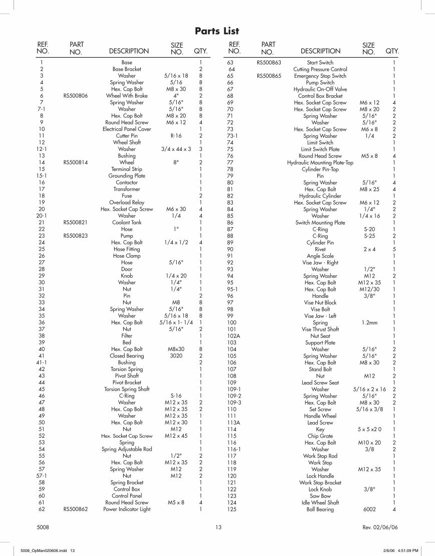
Parts List
� Base � 2 BaseBracket 2 3 Washer 5/�6x�8 8 4 SpringWasher 5/�6 8 5 Hex.CapBolt M8x30 8 6 RS500806 WheelWithBrake 4" 2 7 SpringWasher 5/�6" 8 7-� Washer 5/�6" 8 8 Hex.CapBolt M8x20 8 9 RoundHeadScrew M6x�2 4 �0 ElectricalPanelCover � �� CutterPin R-�6 2 �2 WheelShaft � �2-� Washer 3/4x44x3 3 �3 Bushing � �4 RS5008�4 Wheel 8" 2 �5 TerminalStrip � �5-� GroundingPlate � �6 Contactor � �7 Transformer � �8 Fuse 2 �9 OverloadRelay � 20 Hex.SocketCapScrew M6x30 4 20-� Washer �/4 4 2� RS50082� CoolantTank � 22 Hose �" � 23 RS500823 Pump � 24 Hex.CapBolt �/4x�/2 4 25 HoseFitting � 26 HoseClamp � 27 Hose 5/�6" � 28 Door � 29 Knob �/4x20 � 30 Washer �/4" � 3� Nut �/4" � 32 Pin 2 33 Nut M8 8 34 SpringWasher 5/�6" 8 35 Washer 5/�6x�8 8 36 Hex.CapBolt 5/�6x�-�/4 � 37 Nut 5/�6" 2 38 Filter � 39 Bed � 40 Hex.CapBolt M8x30 8 4� ClosedBearing 3020 2 4�-� Bushing 2 42 TorsionSpring � 43 PivotShaft � 44 PivotBracket � 45 TorsionSpringShaft � 46 C-Ring S-�6 � 47 Washer M�2x35 2 48 Hex.CapBolt M�2x35 2 49 Washer M�2x35 � 50 Hex.CapBolt M�2x30 � 5� Nut M�2 � 52 Hex.SocketCapScrew M�2x45 � 53 Spring � 54 SpringAdjustableRod � 55 Nut �/2" 2 56 Hex.CapBolt M�2x35 2 57 SpringWasher M�2 2 57-� Nut M�2 2 58 SpringBracket � 59 ControlBox � 60 ControlPanel � 6� RoundHeadScrew M5x8 4 62 RS500862 PowerIndicatorLight �
63 RS500863 StartSwitch �64 CuttingPressureControl �65 RS500865 EmergencyStopSwitch �66 PumpSwitch �67 HydraulicOn-OffValve �68 ControlBoxBracket �69 Hex.SocketCapScrew M6x�2 470 Hex.SocketCapScrew M8x20 27� SpringWasher 5/�6" 272 Washer 5/�6" 273 Hex.SocketCapScrew M6x8 273-� SpringWasher �/4 274 LimitSwitch �75 LimitSwitchPlate �76 RoundHeadScrew M5x8 477 HydraulicMountingPlate-Top �78 CylinderPin-Top �79 Pin �80 SpringWasher 5/�6" 48� Hex.CapBolt M8x25 482 HydraulicCylinder �83 Hex.SocketCapScrew M6x�2 284 SpringWasher �/4" 285 Washer �/4x�6 286 SwitchMountingPlate �87 C-Ring S-20 �88 C-Ring S-25 289 CylinderPin �90 Rivet 2x4 59� AngleScale �92 ViseJaw-Right �93 Washer �/2" �94 SpringWasher M�2 295 Hex.CapBolt M�2x35 �95-� Hex.CapBolt M�2/30 �96 Handle 3/8" �97 ViseNutBlock �98 ViseBolt �99 ViseJaw-Left ��00 Spring �.2mm ��0� ViseThrustShaft ��02A NutSeat ��03 SupportPlate ��04 Washer 5/�6" 2�05 SpringWasher 5/�6" 2�06 Hex.CapBolt M8x30 2�07 StandBolt ��08 Nut M�2 2�09 LeadScrewSeat ��09-� Washer 5/�6x2x�6 2�09-2 SpringWasher 5/�6" 2�09-3 Hex.CapBolt M8x30 2��0 SetScrew 5/�6x3/8 ���� HandleWheel ���3A LeadScrew ���4 Key 5x5x20 ���5 ChipGrate ���6 Hex.CapBolt M�0x20 2��6-� Washer 3/8 2��7 WorkStopRod ���8 WorkStop ���9 Washer M�2x35 ��20 LockHandle ��2� WorkStopBracket ��22 LockKnob 3/8" ��23 SawBow ��24 IdleWheelShaft ��25 BallBearing 6002 4
DESCRIPTION QTY.
REF.NO.
PARTNO.
SIZENO.
DESCRIPTION QTY.
REF.NO.
PARTNO.
SIZENO.
5008_OpMan020606.indd 13 2/6/06 4:51:09 PM

5008 �4 Rev.02/06/06
184
183
180
181
190(
2)
188
189(
2)19
119
219
318
2
187
185(
2)
186
179
178
194(
2)
198(
2)
199(
2)
200(
2)
201(
2) 205
206 20
7(2)
209(
2)
210(
2)
211(
4)
212(
4)
213(
4)
214(
4)
215(
4)
216(
2)21
7(4)
218(
4)
219(
2)
220(
8)
221(
4)
222
224
22522
6
227
228
234
233
237
238(
2)
239A
123
124(
2)125(
4)12
6(2)
134(
8)
135(
2)
150
151
152
136(
4)
138(
2)
139(
2)
142
140
143
144
145
146
147
149(
2)
148(
2)
154
155(
4)156(
4)
158
159(
4)
162
157
153
160(
4)16
1(4)
164
165
167
166(
2)
171(
2) 172
173
174
175A
163
168(
2)
169(
2) 170(
2)
208
229(
4)
230(
4)231(
2)
232
236(
3)
235
242(
3)
241(
3)
261
260
259
258
257
256
255(
4)
254(
2)
253
243
244(
2)24
5(13
)24
6
247
248
249
251
252
250
(27)
176
177
204
196(
2)19
5(2)
197
223
240
232-
1
194-
1(4)
155-
1(4)
144-
1
236-
1
236-
2
255-
1(4)
141
198-
1(2)
50088"x14" Horizontal Band Saw
5008_OpMan020606.indd 14 2/6/06 4:51:12 PM

5008 �5 Rev.02/06/06
Parts List
�26 IdleWheel 2�34 FlatHeadCrossScrew M4x8 8�35 UpperLatch 2�36 RoundHeadScrew M6x�2 4�37 SpringWasher �/4" 4�38 Brace 2�39 AdjustingValve 2�40 Hose �/4" ��4� Hose 5/�6” ��42 ConnectionTube ��43 Nut �/2" ��44 Washer �/2" ��44-� SpringWasher �/2 ��45 MotorMountBracket ��46 SupportShaft ��47 C-Ring S-�9 ��48 SpringWasher M�2 2�49 Hex.CapBolt M�2x30 2�50 Hex.CapBolt M8x40 ��5� SpringWasher 5/�6" ��52 Washer 5/�6x�8 ��53 MotorTiltPlate ��54 Bushing ��55 Hex.CapBolt M8x40 4�55-� SpringWasher 5/�6 4�56 Washer 5/�6x�8 4�57 MotorMountPlate ��58 Motor ��59 Washer 5/�6x�8 4�60 SpringWasher 5/�6" 4�6� Nut M8 4�62 Key 7x7x30 ��63 RS5008�63 GearBox ��64 Key 7x7x30 ��65 Key 7x7x40 ��66 Bushing 2�67 LockKnob �/4x�3 ��68 Washer 5/�6" 2�69 SpringWasher 5/�6" 2�70 Hex.CapBolt M8x40 2�7� SetScrew M8x�0 2�72 RS5008�72 MotorPulley ��73 RS5008�73 Belt A-38 ��74 RS5008�74 GearBoxPulley ��75A RS5008�75A PulleyCover ��76 Hose 5/�6" ��77 GreaseCup 3/8PT ��78 Washer M�2x35 ��79 Hex.CapBolt M�2x30 ��80 RS5008�80 Blade 8/�2TPI ��8� Bushing ��82 RS5008�82 DriveWheel ��83 Washer M�2x50 ��84 Hex.CapBolt M�2x30 ��85 Hex.CapBolt M6x�2 2�86 Pin ��87 BrushBracket ��88 ChipBrush ��89 Washer �/4 2�90 SpringWasher �/4 2�9� Washer �/4" ��92 SpringWasher �/4" ��93 RoundHeadScrew M6x�2 ��94 SetScrew M8x�0 2�94-� Hex.CapBolt M�2x35 4�95 Hex.CapBolt M�0x30 2�96 SpringWasher M�0 2�97 SettingPlate �
�98 SpringWasher 5/�6 2�98-� Washer 5/�6 2�99 Hex.SocketCapScrew M8x30 2200 RoundHeadScrew M5x8 220� NozzleSupport 2204 Hose �/4" �205 GuideBracket-Right �206 Hose �/4" �207 Connector 2208 GuideBracket-Left �209 Hex.SocketCapScrew M8x20 22�0 BallBearing 22�� SpringWasher 5/�6" 42�2 BladeGuide 42�3 Washer M6 42�4 SpringWasher M6 42�5 Hex.SocketCapScrew M6x20 42�6 CentricShaft 22�7 Hex.SocketCapScrew M8x40 42�8 SpringWasher 5/�6" 42�9 EccentricShaft 2220 BallBearing 822� Washer 5/�6x�8 4222 LockHandle �223 Washer M�2x35 �224 BallBearingSeat �225 BladeGuard �226 Washer �/4x�6 2227 SpringWasher �/4" 2228 HexSocketCapScrew M8x20 �229 RoundHeadScrew M4x6 4230 FlatHeadCrossScrew M4x8 423� CoverLockKnob 2232 FrontLatch �232-� BackLatch �233 Nut �/2" �234 Handle �235 RS5008235 IdlerWheel �236 BallBearing 6205 3236-� Washer W�2x35 �236-2 Hex.CapBolt M�2x20 �237 BladeWheelCover �238 FlatHeadCrossScrew M4x8 2239A WireBrushGuard �240 SlideBracket �24� TrackingAdj.Screw M�6x30 3242 Hex.SocketCapScrew M�0x60 3243 IndicatorScale �244 RoundHeadScrew M5x8 2245 DiscSpring �3246 Washer �247 TensionIndicator �248 ThrustBearing 5��04 �249 SetScrew M8x�0 �250 Handwheel �25� Key 5x5x�0 �252 ExtensionBar �253 TensionShaft �254 Gib 2255 Hex.SocketCapScrew M8x20 4255-� SpringWasher 5/�6 4256 BladeWheelShaft �257 Nut M�6 �258 SetScrew M6x8 �259 Slide �260 Washer M�2x35 �26� Hex.SocketCapScrew M�2x20 �
DESCRIPTION QTY.
REF.NO.
PARTNO.
SIZENO.
DESCRIPTION QTY.
REF.NO.
PARTNO.
SIZENO.
5008_OpMan020606.indd 15 2/6/06 4:51:12 PM

5008 �6 Rev.02/06/06
LIMITED WARRANTY:SUNEX INTERNATIONAL, INC. WARRANTS TO ITS CUSTOMERS THAT THE COMPANY’S SUNEX TOOLS®
BRANDED PRODUCTS ARE FREE FROM DEFECTS IN WORKMANSHIP AND MATERIALS.
SunexInternational,Inc.willrepairorreplaceitsSunexTools®brandedproductswhichfailtogivesatisfactoryserviceduetodefectiveworkmanshipormaterials,baseduponthetermsandconditionsofthefollowingdescribedwarrantyplansattributedtothatspecificproduct.
ThisproductcarriesaONE-YEARwarranty.Duringthiswarrantyperiod,SunexToolswillrepairorreplaceatouroptionanypartorunitwhichprovestobedefectiveinmaterialorworkmanship.
Other important warranty information...Thiswarrantydoesnotcoverdamagetoequipmentortoolsarisingfromalteration,abuse,misuse,damageanddoesnotcoveranyrepairsorreplacementmadebyanyoneotherthanSunexToolsoritsauthorizedwarrantyservicecenters.
TheforegoingobligationisSunexTools’soleliabilityunderthisoranyimpliedwarrantyandundernocircumstancesshallwebeliableforanyincidentalorconsequentialdamages.
Note:Somestatesdonotallowtheexclusionorlimitationofincidentalorconsequentialdamages,sotheabovelimitationorexclusionmaynotapplytoyou.
ReturnequipmentorpartstoSunexToolsoranauthorizedSunexhydraulicwarrantycenter,transportationprepaid.Becertaintoincludeyournameandaddress,evidenceofthepurchasedate,anddescriptionofthesuspecteddefect.
Ifyouhaveanyquestionsaboutwarrantyservice,pleasewritetoSunexTools.Thiswarrantygivesyouspecificlegalrightsandyoumayalsohaveotherrightswhichvaryfromstatetostate.
RepairkitsandreplacementpartsareavailableformanyofSunexToolsproductsregardlessofwhetherornottheproductisstillcoveredbyawarrantyplan.
5008_OpMan020606.indd 16 2/6/06 4:51:12 PM