OPERATING INSTRUCTIONS, SERVICE INSPECTION AND …
8
AEROMOTORS AEROMOTORS BACAU – ROMANIA BACAU – ROMANIA M-14P, M-14P-XDK OPERATING INSTRUCTIONS, SERVICE INSPECTION AND ASSOCIATED MAINTENANCE JULY 2001
Transcript of OPERATING INSTRUCTIONS, SERVICE INSPECTION AND …

AEROMOTORS AEROMOTORS BACAU – ROMANIABACAU – ROMANIA
M-14P, M-14P-XDK
OPERATING INSTRUCTIONS, SERVICE INSPECTION AND
ASSOCIATED MAINTENANCE
JULY 2001

TABLE OF CONTENTS
1. Introduction 32. General 53. Fire combat and labor protection measures 54. General data about the M-14P engine 65. Engine installation sequence on the airplane 66. In flight operation of the engine 107. Engine operation under low ambient temperatures 118. Maintenance schendule 139. Aggregates replacement and adjustment 2910.Engine troubleshooling, causes and
remedies 4511.Engine storage, returning to service from storage 55
and preservation
Page.2

1. INTRODUCTION
1.1 This publication comprises the Operating Instructions for the M-14P engine, that are mandatory to be observed.
1.2 In this publication the following definition and abbreviations will be used :O.I. -Operating Instruction Front View -The observer stands in the front of installed engine propeller shaft (fig.1).Rear View -The observer stands behind the engine (fig.2).
Fig.1 – FRONT VIEW
Page.3

Fig.2 – REAR VIEW
The propeller end of the engine will be referred to as the “Front” and anti- propeller end as the “Rear” of the engine .
Page.4

The terms “right” and “left” are determined by viewing the engine from the rear and looking in the direction in which the propeller shaft points .Directions of rotation are determined when looking from the rear toward the front of the engine .
a.Clockwise -The engine is rotating clockwise .b.Counter clockwise -The engine is rotating counter – clockwise.
PEG -Propeller Engine Group .
The position of the piston inside the cylinder :a.UDC -Upper Dead Center (internal) ;b.LDC -Lower Dead Center (external); TCL -Throttle Control Lever GCM -Greasing and Combustible Materials
1.3 When operating the M-14P engine read also the technical description , the engine logbook and the certificates of the aggregates .
2. GENERAL
2.1 Only the aviation service qualified personnel is allowed to operate the M-14P engine.2.2 Before starting the operation , check the existence of the operation documents and their
appropriation by the operators .2.3 All works made on the engine and its aggregates in service shall be entered in the engine
logbook and the certificates of the aggregates .2.4 During service it is FORBIDDEN to :
- use other types of fuel,oil,grease and compressed gases than those specified in the OI .
- modify the technological succession of the works and operations performed on the engine .
- simultaneously disconnect both magnetos when the engine is running and the throttle valve of the carburetor is completely open .
2.5 When the signaling screen lamp is lit ,watch oil pressure and temperature gauges of the engine and, depending on the situation , the pilot will decide whether to land or not .It is forbidden to perform another flight before ascertaining trouble that made the lamp to lit and correcting the failures .
2.6 The engine mounting shall be replaced by the manufacturing plant only .2.7 The carburetor air intake shall be equipped with an air filter .2.8 It is FORBIDDEN to rotate the propeller shaft before returning to service from storage
the magneto and air compressor .
3 FIRE COMBAT AND LABOUR PROTECTION MEASURES
3.1 During the operation of the engine , the following safety measures shall be observed : - the engine shall be started only when within the plane of rotation of the
propeller there are no people or other foreign objects .- the propeller may be turn over by hand provided the ignition is “off” and at a
temperature less than 80 C of the cylinder heads .- do not switch the ignition if people , foreign bodies or ground equipment are
placed near the engine .- do not leave the cabin of the airplane when the engines is running .
3.2 In case of fire on the engine or if the fuel is burnt in the carburetor , the access of the gasoline to the engine shall be closed , completely open the throttle valve and switch the fire extinguishing system of the airplane .
IT IS FORBIDDEN :
Page.5

- to stop the engine by closing the fire cock in order to prevent the generation of backfires and burning .
- to cover the engine with the hood when the temperature of the cylinder heads is higher than 120C .
3.3 Hoisting units:- They must operate properly ; periodical tests shall be performed and the
results will be recorded .- Do not leave the engine lifted on the hoisting unit and no works shall be
performed while the engine is hooked on .
3.4 No GCM leakage and leaky oil and fuel lines are allowed . The people who came in contact with the GCM , after finishing the work , shall wash their hands with soap and water .
4. GENERAL DATA ABOUT THE M-14P ENGINE
The aviation M-14P engine is a four-stroke engine ,- air cooled - operating with gasoline - 9 radial cylinder engine - the fuel-air mixture is made in the carburetor - rotary compressor .
The M-14P engine is made of the following assemblies :- housing , cylinder ,crank and connecting rod assembly , pistons , reducer ;- gas distribution system;- fuel feed system ;- ignition system ;- lubricating system ;- signaling screen ;
The following aggregates are installed on the engine :- the R-2 speed governor , 04 series is installed on the reducer ;- the AK-14P carburetor ;- two M-9F magnetos ;- the GSR-300M generator ;- the compressed air distributor ;- the DTE-1speedmeter transducer ;- the MN-14A oil pump ;- the 702ML gasoline pump ;- the AK-50A compressor ;are installed on the rear cover of the housing .- two SD-49SMM spark plugs and a starting valve are installed on the cylinder heads .
The fuel fine filtering is installed on the airplane .The engine is started with compressed air .The oil strainer has a signaling screen for metal deposits indicating failure in the master rod bearing or other internal parts.
5. ENGINE INSTALLATION SEQUENCE ON THE AIRPLANE
- Check the existence of the seals , all aggregates and tool kit ;- In case of some lacks , make a visual inspection and send a report to the
supplier of the engine ;- Lift the engine without causing any damages to its parts or aggregates ;
Page.6
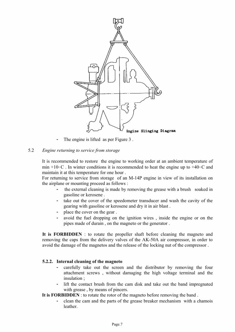
- The engine is lifted as per Figure 3 .
5.2 Engine returning to service from storage
It is recommended to restore the engine to working order at an ambient temperature of min +10C . In winter conditions it is recommended to heat the engine up to +40C and maintain it at this temperature for one hour .For returning to service from storage of an M-14P engine in view of its installation on the airplane or mounting proceed as follows :
- the external cleaning is made by removing the grease with a brush soaked in gasoline or kerosene .
- take out the cover of the speedometer transducer and wash the cavity of the gearing with gasoline or kerosene and dry it in air blast .
- place the cover on the gear .- avoid the fuel dropping on the ignition wires , inside the engine or on the
pipes made of durain , on the magneto or the generator .
It is FORBIDDEN : to rotate the propeller shaft before cleaning the magneto and removing the caps from the delivery valves of the AK-50A air compressor, in order to avoid the damage of the magnetos and the release of the locking nut of the compressor .
5.2.2. Internal cleaning of the magneto- carefully take out the screen and the distributor by removing the four
attachment screws , without damaging the high voltage terminal and the insulation ;
- lift the contact brush from the cam disk and take out the band impregnated with grease , by means of pincers.
It is FORBIDDEN : to rotate the rotor of the magneto before removing the band .- clean the cam and the parts of the grease breaker mechanism with a chamois
leather.
Page.7

- grease the cam surface (that is cleaned up to brighlustre) and the lever needle with oil by using a pincers ,without any leaks of oil on the contacts and the parts near them .
- in case of the magnetos stored for a long time (min two years) , use a pipette to drop oil on the wick coming out from the cam and grease the cam .wipe the grease breaker contacts with chamois leather soaked in clean alcohol.
It is FORBIDDEN : -to wash the grease breaker mechanism and the cam with gasoline .
- the presence of corrosion on the needle of the grease breaker and the cam working profile . Otherwise , these parts shall be replaced .
- install back the parts of the magneto and wirelock the attachment screws of the joint .
- unscrew the caps , the dehydrator plugs and the adapters from the holes for the spark plugs and the exhaust parts of all cylinders, unscrew the drain plugs from the inlet pipes of the cylinders 4,5,6 and remove the signaling screen.
5.2.3. Internal cleaning of the air compressor- remove the cover of the discharge valve , the safetylock, the sieve , the filter
cell and the second sieve ;- clean the external surfaces and the flange of the compressor with gasoline ;- drain out the storage grease from the compressor by rotating the propeller
shaft clockwise (front view) . Rotate the shaft by using a special wrench or the propeller till the complete exhaustion of the grease from the cylinder of the compressor . If the engine is installed on the plane , after rotating the propeller shaft ,unscrew the ring (fig 3);
- wash the screen cell in gasoline and dry it in air blast ;- assembly the sieve , the screen cell ,the second sieve back in place and lock
them with springy lock , install the cover of the discharge valve ;- remove the grease from the high and lateral cylinders by using grease pump
,the piston being in the UDC position;- wash the signaling screen and install it back.
5.2.4. After the internal returning to service from storage of the engine on the mounting :- screw in caps or spark plugs ;- screw in and wirelock the drain plugs of the inlet pipes from the cylinders
4,5,6 ;- assembly the generator on the engine and the filter for fine filtering on the
airplane ;- install the screen cell ;- install caps on the aggregates as well as on the drain holes of all the
cylinders ;
5.2.5. After the internal returning to service from storage of the engine on the airplane - check if the caps , the dehydrator plugs and the adapters have been removed
from the holes provided for the spark plugs of all the cylinders;- assembly the front and rear spark plugs back in place ;- screw in and wirelock the drain caps of the of the inlet pipes of the cylinders
4,5,6 .
5.2.6. The internal returning to service from storage of the AK-14P carburetor is made as per par. 9.5.3
5.2.7. The returning to service from storage of the 702ML fuel pump :
Page.8