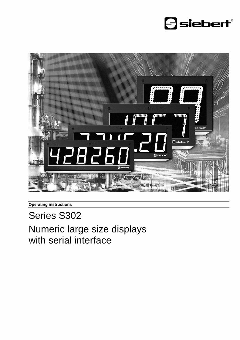
Operating instructions Series S302 Numeric large size ...
25
Operating instructions Series S302 Numeric large size displays with serial interface
Transcript of Operating instructions Series S302 Numeric large size ...
Pos: 2 /Siebert/Bedienungsanl eitungen/Serie S302/SX302/Ti telseiten/S302 SER @ 0\mod_1316097598153_48.docx @ 2373 @ @ 1
Operating instructions
Series S302
Numeric large size displays with serial interface Pos: 3 /Siebert/Seitenumbruch @ 0\mod_1314194553878_0.docx @ 150 @ @ 1

BAL S302 SER 4.01 2/25
Pos : 4 /Siebert/Bedienungsanl eitungen/Gerätebeschr eibung Grossanzeigen all e Serien/Kontakt @ 1\mod_1339668951540_48.docx @ 4323 @ 1 @ 1
1 Contact
www.siebert-group.com
GERMANY
Siebert Industrieelektronik GmbH Siebertstrasse, D-66571 Eppelborn P.O. Box 11 30, D-66565 Eppelborn Phone +49 (0)6806 980-0, Fax +49 (0)6806 980-999 email [email protected]
AUSTRIA
Siebert Österreich GmbH Mooslackengasse 17. A-1190 Wien Phone +43 (0)1 890 63 86-0, Fax +43 (0)14 890 63 86-99 email [email protected]
FRANCE
Siebert France Sarl 33 rue Poincaré, F-57200 Sarreguemines P.O. Box 90 334, F-57203 Sarreguemines Cédex Phone +33 (0)3 87 98 63 68, Fax +33 (0)3 87 98 63 94 email [email protected]
THE NETHERLANDS
Siebert Nederland B.V. Jadedreef 26, NL-7828 BH Emmen Phone +31 (0)591-633444, Fax +31 (0)591-633125 email [email protected]
SWITZERALND
Siebert AG Bützbergstrasse 2, P.O. Box 91, CH-4912 Aarwangen Phone +41 (0)62 922 18 70, Fax +41 (0)62 922 33 37 email [email protected]
Pos: 5 /Siebert/Seitenumbruch @ 0\mod_1314194553878_0.docx @ 150 @ @ 1

BAL S302 SER 4.01 3/25
Pos : 6 /Siebert/Bedienungsanl eitungen/Gerätebeschr eibung Grossanzeigen all e Serien/R echtlicher Hi nweis @ 1\mod_1339668878995_48.docx @ 4317 @ 1 @ 1
2 Legal note
© Siebert Industrieelektronik GmbH
This operation manual has been prepared with the utmost care. However, we do not accept any liability for possible errors. We always appreciate your suggestions for improvement, corrections, comments and proposals. Please contact us: [email protected]
Siebert®, LRD
® and XC-Board
® are registered trademarks of Siebert Industrieelektronik GmbH. All
other product names mentioned herein may be trademarks or registered trademarks of their respective owners.
We reserve the right to make alterations to the technical data and delivery options without notice. - All rights reserved, including the rights of translation. No part of this document may in any form or by any means (print, photocopy, microfilm or any other process) be reproduced or by using electronic systems be processed, copied or distributed without our written permission.
Pos: 7 /Siebert/Seitenumbruch @ 0\mod_1314194553878_0.docx @ 150 @ @ 1
BAL S302 SER 4.01 4/25
Pos : 8 /Siebert/Bedienungsanl eitungen/M odul Inhaltsverzeichnis @ 1\mod_1352981287156_48.docx @ 5155 @ @ 1
Table of contents
1 Contact 2
2 Legal note 3
3 Safety precautions 6
Important information ......................................................................................................................................... 6
Safety ................................................................................................................................................................. 6
Intended use ....................................................................................................................................................... 6
Mounting and installation .................................................................................................................................... 6
Grounding ........................................................................................................................................................... 6
EMC measures ................................................................................................................................................... 7
Disposal .............................................................................................................................................................. 7
4 Unit description 8
Model designation .............................................................................................................................................. 8
Unit construction ................................................................................................................................................. 8
Principle circuit diagram ..................................................................................................................................... 9
Central Processing Unit .................................................................................................................................... 10
Serial Interface ................................................................................................................................................. 10
Function inputs ................................................................................................................................................. 10
Auxiliary voltage ............................................................................................................................................... 10
Menu display .................................................................................................................................................... 11
Menu buttons .................................................................................................................................................... 11
Switching output ............................................................................................................................................... 11
Status indicators ............................................................................................................................................... 11
Power supply .................................................................................................................................................... 11
5 Control 12
Serial Interface ................................................................................................................................................. 12
Interface parameter .......................................................................................................................................... 12
Ignore characters ............................................................................................................................................. 12
Addressing ........................................................................................................................................................ 12
Flashing ............................................................................................................................................................ 12
Brightness ......................................................................................................................................................... 12
Blanking ............................................................................................................................................................ 13
LED color .......................................................................................................................................................... 13
Switching output ............................................................................................................................................... 13
Time-out ........................................................................................................................................................... 13
Decimal point .................................................................................................................................................... 13
Leading zero suppression ................................................................................................................................ 13
Display test ....................................................................................................................................................... 14

BAL S302 SER 4.01 5/25
Demo operation mode ...................................................................................................................................... 14
ESC sequences ................................................................................................................................................ 14
Power-on reset ................................................................................................................................................. 14
Character set .................................................................................................................................................... 14
6 Parametrization 15
Menu ................................................................................................................................................................. 15
Menu operation................................................................................................................................................. 15
Menu table ........................................................................................................................................................ 16
7 Notes on RS485 interface configuration 18
Menu settings ................................................................................................................................................... 18
Data lines .......................................................................................................................................................... 18
Applikation example A ...................................................................................................................................... 19
Applikation example B ...................................................................................................................................... 19
Applikation example C ...................................................................................................................................... 19
Applikation example D ...................................................................................................................................... 20
8 Technical data 21
Unit properties .................................................................................................................................................. 21
Max. power consumption ................................................................................................................................. 22
Switching output ............................................................................................................................................... 22
Screw-type terminals ........................................................................................................................................ 22
Housing colors .................................................................................................................................................. 22
Front frame ....................................................................................................................................................... 23
Ambient conditions ........................................................................................................................................... 23
Measurements and weights ............................................................................................................................. 24
=== Ende der Liste für Textmar ke Inhalt1 ===
Pos: 10 /Si ebert /Seitenumbr uch @ 0\mod_1314194553878_0.docx @ 150 @ @ 1
BAL S302 SER 4.01 6/25
Pos : 11 /Si ebert /Bedi enungsanlei tungen/Ger ätebeschrei bung Gr ossanzeigen alle Serien/Sicherheitshinweise Gr ossanzeigen @ 1\mod_1339668771568_48.docx @ 4311 @ 12222222 @ 1
3 Safety precautions
Important information
Read these operating instructions before starting the unit. They provide you with important information on the use, safety and maintenance of the units. This helps you to protect yourself and prevent damage to the unit.
Information intended to help you to avoid death, bodily harm or considerable damage to property is highlighted by the warning triangle shown here; it is imperative that this information be properly heeded.
The operating instructions are intended for trained professional electricians familiar with the safety standards of electrical technology and industrial electronics.
Store these operating instructions in an appropriate place.
The manufacturer is not liable if the information in these operating instructions is not complied with.
Safety
Components inside the units are energized with electricity during operation. For this reason, mounting and maintenance work may only be performed by professionally-trained personnel while observing the corresponding safety regulations.
The repair and replacement of components and modules may only be carried out by the manufacturer for safety reasons and due to the required compliance with the documented unit properties.
The units do not have a power switch. They are operative as soon as the operating voltage is applied.
Intended use
The units are intended for use in industrial environments. They may only be operated within the limit values stipulated by the technical data.
When configuring, installing, maintaining and testing the units, the safety and accident-prevention regulations relevant to use in each individual case must be complied with.
Trouble-free, safe operation of the units requires proper transport, storage, installation, mounting and careful operation and maintenance of the units.
Mounting and installation
The attachment options for the units were conceived in such a way as to ensure safe, reliable mounting.
The user must ensure that the attachment hardware, the unit carrier and the anchoring at the unit carrier are sufficient to securely support the unit under the given surrounding conditions.
The units are to be mounted in such a way that they can be opened up while mounted. Sufficient space for the cables must be available in the unit near the cable entries.
Sufficient space is to be kept clear around the units to ensure air circulation and to prevent the build-up of heat resulting from use. The relevant information must be heeded in the case of units ventilated by other means.
When the housing fasteners are opened, the front frame of the housing hinges out upward or downward (depending on the unit version) automatically.
Grounding
All devices are equipped with a metal housing. They comply with safety class I and require a protective earth connection. The connecting cable for the operating voltage must contain a protective earth wire of a sufficient cross section (DIN VDE 0106 part 1, DIN VDE 0411 part 1).

BAL S302 SER 4.01 7/25
EMC measures
The devices comply with the EU Directive 2004/108/EC (EMC Directive) and provide the required interference immunity. Observe the following when connecting the operating voltage and data cables:
Use shielded data cables.
The data and operating voltage cables must be laid separately. They may not be laid together with heavy-current cables or other interference-producing cables.
The cable thickness must be properly assessed (DIN VDE 0100 Part 540).
The cable lengths inside the units are to be kept as short as possible to prevent interference. This applies especially to unshielded operating voltage cables. Shielded cables are also to be kept short due to any interference which might be emitted by the shielding.
Neither excessively long cables nor cable loops may be placed inside the units.
The connection of the cable shielding to the functional ground (PE) must be as short and low-impedance as possible. It should be made directly to the mounting plate over a large area with a conductive clip:
contro l
conductive c lam p
m outing p la te
data line term inals
bare
m etal surface
The cable shielding is to be connected at both cable ends. If equipotential bonding currents are expected due to the cable arrangement, electrical isolation is to be performed on one side. In this case, capacitive connection (approx. 0.1μF/600 V AC) of the shielding on the isolated side must occur.
Disposal
Units or unit parts which are no longer needed are to be disposed of in accordance with the regulations in effect in your country.
Pos: 12 /Si ebert /Seitenumbr uch @ 0\mod_1314194553878_0.docx @ 150 @ @ 1

BAL S302 SER 4.01 8/25
Pos : 13 /Si ebert /Bedi enungsanlei tungen/Seri e S302/SX302/Gerätebeschrei bung/ÜBS Ger ätebeschrei bung @ 0\mod_1315481662300_48.docx @ 1005 @ 1 @ 1
4 Unit description
Pos: 14 /Si ebert /Bedi enungsanlei tungen/Seri e S302/SX302/Gerätebeschrei bung/S302 Geltungsber eich SER @ 0\mod_1315481831824_48.docx @ 1037 @ 2 @ 1
Model designation
This manual applies to units with the following model designation (x = the 'x's in the model designation indicate the size and design of the units (see Chapter 8):
S302-xx/xx/xx-xxx/xx-S0 (Interface RS485/RS232) S302-xx/xx/xx-xxx/xx-T0 (Interface TTY 20mA/RS232)
Pos: 15 /Si ebert /Bedi enungsanlei tungen/Seri e S302/SX302/Gerätebeschrei bung/S302 Geräteaufbau AN A, CAN , ETH , D VN, FR Q, IBS, MDB, MDB TCP, PAR, PFB, PFN, PFN IR T, SER , ZLR @ 0\mod_1315481910892_48.docx @ 1061 @ 2 @ 1
Unit construction
The following figure shows model type S302-05/10/xx-xxx/xx-xx as example for the other model types. The front frame of the housing is locked with quick-action releases. When opening the unit the front frame hinges downward.
The following figure shows the unit when open.
Central
Processing
Unit
Power supply
unit
Display modules
Units with double-sided display show the same information on the front and on the rear side. Pos: 16 /Si ebert /Bedi enungsanlei tungen/Seri e S302/SX302/Gerätebeschrei bung/S302 Prinzipschaltbil d SER @ 0\mod_1315481982407_48.docx @ 1085 @ 2 @ 1
BAL S302 SER 4.01 9/25
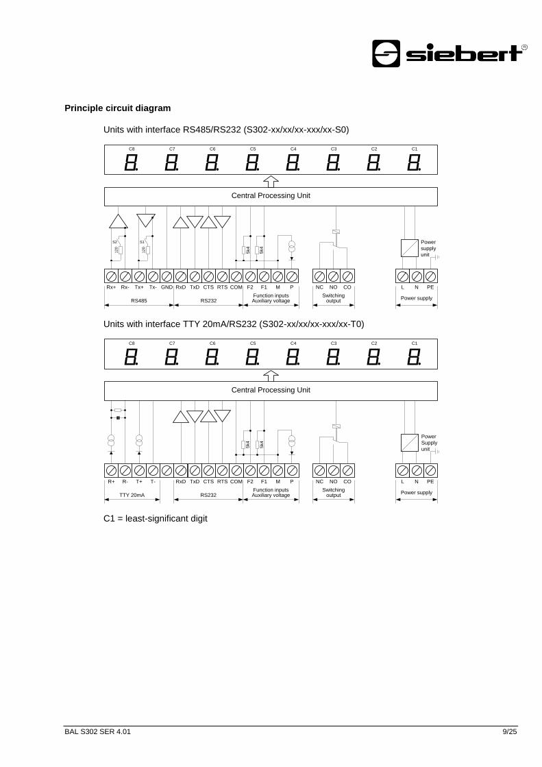
Principle circuit diagram
Units with interface RS485/RS232 (S302-xx/xx/xx-xxx/xx-S0)
Power
supply
unit
L N PE
Power supplyFunction inputs
F2 F1 P
RS232RS485
Rx+ Rx- Tx- GND RxD TxD CTS RTS
C6 C5 C4 C3
8. 8. 8. 8. 8.C7
8. 8.C2 C1
8.C8
Central Processing Unit
S2
12
0
S1
12
0
Tx+ COM CO
Switching output
NC NOM
Auxiliary voltage
5k4
5k4
Units with interface TTY 20mA/RS232 (S302-xx/xx/xx-xxx/xx-T0)
Power
Supply
unit
L N PE
Power supply
F2 F1 P
RS232TTY 20mA
R+ R- T- RxD TxD CTS RTS
C6 C5 C4 C3
8. 8. 8. 8. 8.C7
8. 8.C2 C1
8.C8
Central Processing Unit
T+ COM CO
Switching output
NC NOM
5k4
5k4
Function inputsAuxiliary voltage
C1 = least-significant digit Pos: 17 /Si ebert /Bedi enungsanlei tungen/Seri e S302/SX302/Gerätebeschrei bung/S302 Steuerr echner SER @ 0\mod_1315482116772_48.docx @ 1121 @ 2 @ 1 xxx

BAL S302 SER 4.01 10/25
Central Processing Unit
The following figure shows the Central Processing Unit, located in the lower part of the housing.
88888 8
Screw terminal strip
Menu display
Menu buttons
OUT
ERR
DATA
S1 S2
Switch S1/S2 only with S302-xx/xx/xx-xxx/xx-S0 Pos: 18 /Si ebert /Bedi enungsanlei tungen/Seri e S302/SX302/Gerätebeschrei bung/S302 Serielle Schnitts tell e SER, WTS @ 0\mod_1315482244923_48.docx @ 1145 @ 2 @ 1
Serial Interface
The serial interface is located on the screw-type terminal strip of the control computer. Depending on the unit version it has the following formats:
RS485 and RS232 (S302-xx/xx/xx-xxx/xx-S0) TTY 20mA and RS232 (S302-xx/xx/xx-xxx/xx-T0)
The type of interface format is set in menu item 1 (see Chapter 6).
The switches S1 and S2 serve for locking the data lines of the RS485 (see Chapter 7).
Preferably, the interfaces RS485 or TTY 20 mA are to be used for activation. They are galvanically isolated from all other electric circuits and provide optimum preconditions for a reliable and safe operation of the devices due to its physical characteristics.
The interface RS232 is determined for testing purposes and is not recommended for activation because of its physical properties.
Pos: 19 /Si ebert /Bedi enungsanlei tungen/Ger ätebeschrei bung Gr ossanzeigen Ü bereinsti mmung versch. Seri en/Gerätebeschr eibung S302/SX302 SX502/Funktionseingänge S302 SER , SX502 SER @ 0\mod_1315482406687_48.docx @ 1199 @ 2 @ 1
Function inputs
The function inputs are located on the screw-type terminal strip of the control computer. They allow reduction in brightness and flashing of the display, independently of commands via the serial interface (see Chapter 5).
Pos: 20 /Si ebert /Bedi enungsanlei tungen/Ger ätebeschrei bung Gr ossanzeigen Ü bereinsti mmung versch. Seri en/Gerätebeschr eibung S302/SX302 SX502/Funktionseing.S302AN A,CAN ,DVN ,ETH ,IBS,MD B,MD BTCP,NTP,PFN ,PFN IRT,SER ,TMR,WTH,WTS, SX502 s.u. @ 0\mod_1315482328929_48.docx @ 1151 @ @ 1
The function inputs are designed for the following signal voltages:
Signal voltage: L = -3.5...+5 V (open input = L) H = +18...30 V (active H), M = reference potential
Pos: 21 /Si ebert /Bedi enungsanlei tungen/Ger ätebeschrei bung Gr ossanzeigen alle Serien/Hilfsspannung Grossanzeigen ( S302 alle ausser PFB) @ 0\mod_1315487007476_48.docx @ 1624 @ 2 @ 1
Auxiliary voltage
The units supply terminal P with an auxiliary voltage galvanically isolated from the operating voltage (24 V ± 20%, max. 50 mA, M = reference potential). It can be used for supplying power to the current loop or as H signal for the function inputs.
Pos: 22 /Si ebert /Bedi enungsanlei tungen/Seri e S302/SX302/Gerätebeschrei bung/S302 Menüanzeig e (all e S302) @ 0\mod_1315482547561_48.docx @ 1223 @ 2 @ 1

BAL S302 SER 4.01 11/25
Menu display
The parameterization of the units is carried out in a menu of the menu display (see Chapter 6).In normal mode, the menu display corresponds to the main display. For devices with more than six
positions, is shown in the menu display in normal operation. Pos: 23 /Si ebert /Bedi enungsanlei tungen/Ger ätebeschrei bung Gr ossanzeigen alle Serien/M enütasten Gr ossanzeigen @ 0\mod_1315482591663_48.docx @ 1229 @ 2 @ 1
Menu buttons
The menu buttons are used to control the menu (see Chapter 6). Pos: 24 /Si ebert /Bedi enungsanlei tungen/Seri e S302/SX302/Gerätebeschrei bung/S302 Schaltausgang C AN, D VN, ETH, IBS, MDB, MDB TCP, PFN, PFN IRT, SER, WTS @ 0\mod_1315482634499_48.docx @ 1235 @ 2 @ 1
Switching output
The devices dispose of a switching output (relay) with potential-free make contact (NC, NO, CO). Pos: 25 /Si ebert /Bedi enungsanlei tungen/Seri e S302/SX302/Gerätebeschrei bung/S302 Statusanzeigen MD B, SER, WTS @ 0\mod_1315482734251_48.docx @ 1253 @ 2 @ 1
Status indicators
The status indicators (LEDs) of the control computer have the following meaning:
DATA Data are received ERR Error in data format OUT Switching output is active
Pos: 26 /Si ebert /Bedi enungsanlei tungen/Ger ätebeschrei bung Gr ossanzeigen alle Serien/Betri ebsspannung Grossanzeigen @ 0\mod_1315494019425_48.docx @ 1864 @ 2 @ 1
Power supply
The screw-type terminals for the power supply are located on the power supply unit in the bottom section of the housing. They have the following designations:
Devices for a power supply 115 V AC or 230 V AC L, N and PE Devices for a power supply 24 V DC +, – and PE
Pos: 27 /Si ebert /Seitenumbr uch @ 0\mod_1314194553878_0.docx @ 150 @ @ 1

BAL S302 SER 4.01 12/25
Pos : 28 /Si ebert /Bedi enungsanlei tungen/Seri e S302/SX302/Ans teuerung/ÜBS Ans teuerung @ 0\mod_1315481589472_48.docx @ 998 @ 1 @ 1
5 Control
Pos: 29 /Si ebert /Bedi enungsanlei tungen/Seri e S302/SX302/Ans teuerung/S302 Seri elle Schni ttstelle SER, WTS @ 0\mod_1315482800539_48.docx @ 1289 @ 2 @ 1
Serial Interface
Depending on the device model the serial interface has the following formats:
RS485 and RS232 (S302-xx/xx/xx-xxx/xx-S0) TTY 20mA and RS232 (S302-xx/xx/xx-xxx/xx-T0)
The interface format is set in menu item 1 (see Chapter 5).
With interface RS485 different settings are possible in menu item 1 (see Chapter 7 Notes on RS485 interface configuration).
With interface RS232 the RTS/CTS Handshake is always active. Pos: 30 /Si ebert /Bedi enungsanlei tungen/Seri e S302/SX302/Ans teuerung/S302 Schnit tstellenpar ameter SER @ 0\mod_1315483068515_48.docx @ 1301 @ 2 @ 1
Interface parameter
Data format, parity, baud rate, protocol and protocol reply are set in menu items 2 to 6.
If protocol 3964 is selected in menu item 5, 8 bit data format and even parity are set automatically.
If setting 'Echo' is selected in menu item 6, the device transmits the received data telegrams via the serial interface.
Pos: 31 /Si ebert /Bedi enungsanlei tungen/Seri e S302/SX302/Ans teuerung/S302 Zeichen ignorier en SER, WTS @ 0\mod_1315483094288_48.docx @ 1307 @ 2 @ 1
Ignore characters
If the characters to be represented in the display do not start on the first data telegram position, in menu item 7 you can set how many preceding characters have to be ignored.
Pos: 32 /Si ebert /Bedi enungsanlei tungen/Seri e S302/SX302/Ans teuerung/S302 Adr essi erung SER, WTS @ 0\mod_1315483148632_48.docx @ 1313 @ 2 @ 1
Addressing
If no addressing is desired, select the setting 0 in menu item 8.
If the devices are to be selectively addressable, they receive an individual address. In menu item 8, it is defined if the address has one, two or three digits.
In menu item 9, the address is set (1…999). The address 0 is reserved as broadcast address, with which all devices are addressed. If the device receives the address 0, it does not send back a telegram reply.
If the address 0 is set in menu item 9, the device is addressed with any address but it does not send back a telegram reply.
Pos: 33 /Si ebert /Bedi enungsanlei tungen/Seri e S302/SX302/Ans teuerung/S302 Blinken ETH, SER , WTS @ 0\mod_1315483174789_48.docx @ 1331 @ 2 @ 1
Flashing
Flashing of the display can be controlled with the following commands:
$F1 Flashing on
$F0 Flashing off
If $F1 is sent in the data telegram, the succeeding digits will flash until the end of the data telegram or
until $F0 is sent in the data telegram.
Flashing of the display can also be activated by application of the H signal to functional input F1 (priority over commands).
For devices provided with an LRD® display flashing is not possible.
Pos: 34 /Si ebert /Bedi enungsanlei tungen/Seri e S302/SX302/Ans teuerung/S302 H elligkeit ETH, SER, WTS @ 0\mod_1315483265518_48.docx @ 1349 @ 2 @ 1
Brightness
The brightness of the display can be reduced with the following command:
$L1 Reduced brightness
$L0 Normal brightness
BAL S302 SER 4.01 13/25
The brightness of the display can also be reduced with an H signal applied to functional input F2 (priority over commands).
For devices provided with an LRD®
display brightness reduction is not possible Pos: 35 /Si ebert /Bedi enungsanlei tungen/Seri e S302/SX302/Ans teuerung/S302 D unkles teuerung ETH , SER, WTS @ 0\mod_1315483539504_48.docx @ 1360 @ 2 @ 1
Blanking
The display can be blanked with the following command (priority over flashing):
$B1 Blanking on
$B0 Blanking off Pos: 36 /Si ebert /Bedi enungsanlei tungen/Seri e S302/SX302/Ans teuerung/S302 LED-Farbe ETH, SER @ 0\mod_1319712301658_48.docx @ 3411 @ 2 @ 1
LED color
Devices with switchable LED color display the characters in red color. If the command $A… is sent in
the data telegram the following characters are displayed in the corresponding LED color:
$A0 Red
$A1 Green
$A2 Orange Pos: 37 /Si ebert /Bedi enungsanlei tungen/Seri e S302/SX302/Ans teuerung/S302 Schaltausgang ETH , SER, WTS @ 0\mod_1315484287695_48.docx @ 1378 @ 2 @ 1
Switching output
The devices dispose of a switching output (relay) with potential-free change-over contact (NC, NO, CO).
When setting OFF in menu item r, the switching output can be controlled with the following commands:
$Q@1 Activate switching contact
$Q@0 Deactivate switching contact
The relay only switches after realized telegram ending
When setting 1, 2 or 4 in menu item r, the command $Q@1 causes a wiping pulse at the switching
output with a duration of 1, 2 or 4 seconds.
When setting A1, A2 or A4 in menu item r, each telegram at the switching output automatically gives a wiping pulse with a duration of 1, 2 or 4 seconds.
The wiping function is suitable, for example, for activating optical or acoustic signal transmitters.
The status indicator OUT of the control computer is lighted with active switching output. Pos: 38 /Si ebert /Bedi enungsanlei tungen/Seri e S302/SX302/Ans teuerung/S302 Ti me-out ETH, MDB, MDB TCP, SER , WTS @ 0\mod_1315484371889_48.docx @ 1390 @ 2 @ 1
Time-out
In menu item t, it is possible to set whether a time-out occurs, and if so, after what time. Time-out means that minus signs appear on the display if the device has not received a data telegram after a defined time.
Pos: 39 /Si ebert /Bedi enungsanlei tungen/Seri e S302/SX302/Ans teuerung/S302 D ezi malpunkt ETH, SER, WTS @ 0\mod_1315484404394_48.docx @ 1408 @ 2 @ 1
Decimal point
A fixed decimal point can be set in menu item A.
The decimal point can also be controlled via the serial interface. In menu item A you must select setting 0 (no decimal point).
A decimal point set in menu item A has priority.
Devices with a LRD® display have no decimal points.
Pos: 40 /Si ebert /Bedi enungsanlei tungen/Seri e S302/SX302/Ans teuerung/S302 Vor nullenausblendung AN A, D VN, ETH , IBS, MDB, MD B TC P, PAR , PFB, PFN, PFN IRT, SER, WTS, ZLR @ 0\mod_1315484430970_48.docx @ 1414 @ 2 @ 1
Leading zero suppression
In menu item C it is set if leading zeros are to be displayed or suppressed. Pos: 41 /Si ebert /Bedi enungsanlei tungen/Seri e S302/SX302/Ans teuerung/S302 Displaytest ETH, SER, WTS @ 0\mod_1315484524558_48.docx @ 1432 @ 2 @ 1
BAL S302 SER 4.01 14/25
Display test
In menu item F, you can set whether a display test is to be performed after the operating voltage is applied.
The display test can also be controlled with the following commands:
$T1 Display test on
$T0 Display test off
The display test has priority over blanking and flashing. Pos: 42 /Si ebert /Bedi enungsanlei tungen/Seri e S302/SX302/Ans teuerung/S302 D emo-Betrieb ANA, CAN , DCF, DVN , ETH, IBS, MD B, MDB TC P, PAR, PFB, PFN, PFN IRT, SER, WTS, ZLR @ 0\mod_1315484550592_48.docx @ 1438 @ 2 @ 1
Demo operation mode
If the setting is selected in menu item F, random characters are displayed. In this case, it is impossible to control the unit.
Pos: 43 /Si ebert /Bedi enungsanlei tungen/Seri e S302/SX302/Ans teuerung/S302 ESC- Seq uenzen ETH , SER, WTS @ 0\mod_1315484574013_48.docx @ 1444 @ 2 @ 1
ESC sequences
The character $ can be used in the commands instead of <ESC>, e.g. <ESC>L1 instead of $L1. Pos: 44 /Si ebert /Bedi enungsanlei tungen/Seri e S302/SX302/Ans teuerung/S302 Einschaltr eset C AN, D VN, ETH, IBS, MDB, MDB TCP, PAR , PFB, PFN , PFN IRT , SER, WTH, WTS @ 0\mod_1315484598667_48.docx @ 1450 @ 2 @ 1
Power-on reset
After power-on, minus signs are displayed to signalize that the unit is ready for operation. If a display test has been preselected in menu item F, it will run beforehand.
Pos: 45 /Si ebert /Bedi enungsanlei tungen/Seri e S302/SX302/Ans teuerung/S302 Zeichensatz CAN, DVN , ETH, IBS, MD B, MDB TC P, PFB, PFN, PFN IRT , SER, WTS @ 0\mod_1315484621600_48.docx @ 1456 @ 2 @ 1
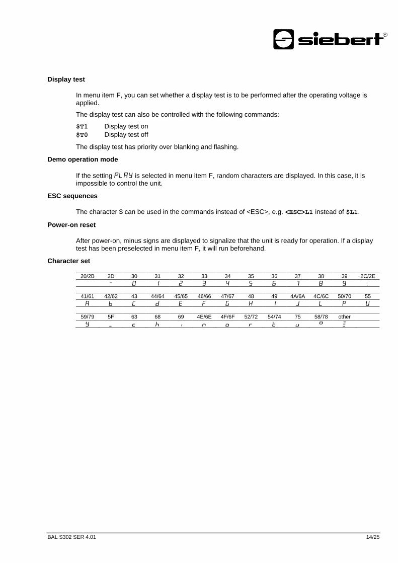
Character set
20/2B 2D 30 31 32 33 34 35 36 37 38 39 2C/2E
8 .
41/61 42/62 43 44/64 45/65 46/66 47/67 48 49 4A/6A 4C/6C 50/70 55
59/79 5F 63 68 69 4E/6E 4F/6F 52/72 54/74 75 58/78 other
Pos: 46 /Si ebert /Seitenumbr uch @ 0\mod_1314194553878_0.docx @ 150 @ @ 1

BAL S302 SER 4.01 15/25
Pos : 47 /Si ebert /Bedi enungsanlei tungen/Seri e S302/SX302/Par ametri erung/ÜBS Par ametrierung @ 0\mod_1315481752944_48.docx @ 1019 @ 1 @ 1
6 Parametrization
Pos: 48 /Si ebert /Bedi enungsanlei tungen/Seri e S302/SX302/Par ametri erung/S302 M enü (alle ausser ZLR) @ 0\mod_1315484655103_48.docx @ 1462 @ 2 @ 1
Menu
The parameterization of the devices is carried out in a menu in the menu display. Pos: 49 /Si ebert /Bedi enungsanlei tungen/Seri e S302/SX302/Par ametri erung/S302 M enübedi enung @ 0\mod_1315484679215_48.docx @ 1468 @ 2 @ 1
Menu operation
To start the menu, press both menu buttons simultaneously (approx. 1 sec.) until the first menu item appears in the menu display. It is now possible to navigate in the menu as follows:
Next menu item Shortly press key [] Page menu items forward Press key [] long Previous menu item Double-click on key [] Page menu items backward Double-click on key [] and keep it pressed
Next setting Shortly press key [] Page settings forward Press key [] long Previous setting Double-click on key [] Page setting backward Double-click on key [] and keep it pressed
To exit the menu shortly press the key [] in menu item U. Depending on the setting in menu item U the settings made are either saved (set) or not saved (escape) or the factory settings are reset (default).
Canceling the menu without saving the settings made is possible by pressing both menu buttons simultaneously (approx. 1 sec.). It will occur automatically if 60 seconds pass without a menu button being pressed.
Once the menu is closed, the device behaves in the same manner as when the operating voltage was applied.
In the menu mode the character appears in the main display. Control of the display is not possible in menu mode.
Pos: 50 /Si ebert /Bedi enungsanlei tungen/Par ametrierung Gr ossanzeigen Ü ber einsti mmung versch. Serien/M enütabell e Einl eitungssatz S302 alle (ausser WTH) SX502 D VN, ETH, MDB, PFB, SER @ 0\mod_1315484703273_48.docx @ 1474 @ 2 @ 1
BAL S302 SER 4.01 16/25
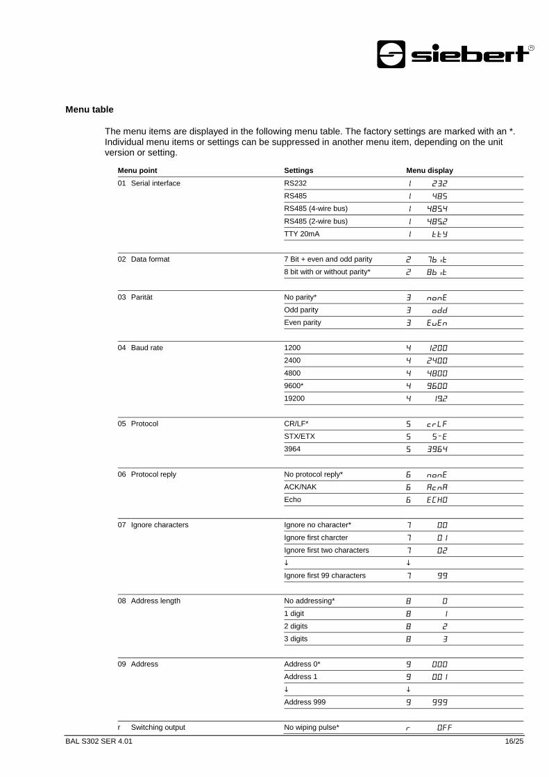
Menu table
The menu items are displayed in the following menu table. The factory settings are marked with an *. Individual menu items or settings can be suppressed in another menu item, depending on the unit version or setting.
Pos: 51 /Si ebert /Bedi enungsanlei tungen/Seri e S302/SX302/Par ametri erung/S302 M enütabelle SER @ 1\mod_1360236864261_48.docx @ 5769 @ @ 1
Menu point Settings Menu display
01 Serial interface RS232
RS485 8
RS485 (4-wire bus) 8.
RS485 (2-wire bus) 8.
TTY 20mA
02 Data format 7 Bit + even and odd parity
8 bit with or without parity* 8
03 Parität No parity*
Odd parity
Even parity
04 Baud rate 1200
2400
4800 8
9600*
19200 .
05 Protocol CR/LF*
STX/ETX
3964
06 Protocol reply No protocol reply*
ACK/NAK
Echo
07 Ignore characters Ignore no character*
Ignore first charcter
Ignore first two characters
Ignore first 99 characters
08 Address length No addressing* 8
1 digit 8
2 digits 8
3 digits 8
09 Address Address 0*
Address 1
Address 999
r Switching output No wiping pulse*

BAL S302 SER 4.01 17/25
Wiping pulse 1 sec.
Wiping pulse 2 sec.
Wiping pulse 4 sec.
Automatic wiping pulse 1 sec.
Automatic wiping pulse 2 sec.
Automatic wiping pulse 4 sec.
t Time-out No time-out*
Time-out after 2 s
Time-out after 4 s
Time-out after 8 s 8
Time-out after 16 s
Time-out after 32 s
Time-out after 64 s
Time-out after 128 s 8
A Decimal point No decimal point*
Decimal point digit C1 .
Decimal point digit C2 .
Decimal point digit C8 8.
C Leading zeros Leading zeros not displayed* .
Leading zeros displayed .
F Display test No display test at power on*
Display test at power on 8888
Demo operation mode
U Saving Saving parameters* (Set)
Not saving parameters (Escape)
Restore to factory settings (Default)
Pos: 52 /Si ebert /Seitenumbr uch @ 0\mod_1314194553878_0.docx @ 150 @ @ 1

BAL S302 SER 4.01 18/25
Pos : 53 /Si ebert /Bedi enungsanlei tungen/Seri e S302/SX302/Pr ojektier ungshinweise zu R S485/ÜBS Proj ekti erungshi nweise zu R S485 @ 0\mod_1315484806512_48.docx @ 1481 @ 1 @ 1
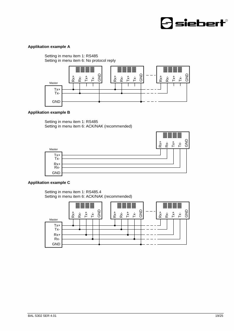
7 Notes on RS485 interface configuration
Pos: 54 /Si ebert /Bedi enungsanlei tungen/Proj ektier ungshinweise zu R S485 Gr ossanzeigen Ü berei nsti mmung versch. Seri en/Menüei nst ellungen S302 SER, WTS, SX502 SER @ 0\mod_1318496686697_48.docx @ 3045 @ 2 @ 1
Menu settings
The interface format RS485 allows the settings 8, 8. and 8. in the menu item 1 (see Chapter 6). The selected setting depends on whether the protocol reply is to be sent by the display:
Protocol-
answer?
Used
Multiple
display
control
4-wire-bus
Single
display
control
Not used
2-wire-bus
see
Application note A
see
Application note B
see
Application note C
see
Application note D
If the display should not send a protocol reply (normal case), application example A applies for activating one or more displays.
If a protocol reply is expected, a differentiation has to be made whether one single unit or more units are to be activated. If one single unit is activated, application example B is valid.
If several units are to be activated, a bus wiring is necessary. You have to differentiate, if a 4-wire bus (full-duplex) or a 2-wire bus (half-duplex) is used. Application example C applies for 4-wire bus and application example D applies for 2-wire bus.
Pos: 55 /Si ebert /Bedi enungsanlei tungen/Seri e S302/SX302/Pr ojektier ungshinweise zu R S485/S302 Datenlei tungen , MDB, SER, WTH, WTS @ 0\mod_1315573961301_48.docx @ 2097 @ 2 @ 1
Data lines
To achieve the highest possible interference immunity, the data lines of the RS485 have to be terminated on both ends. The required resistors are provided in the control computer and can be connected on the screw terminal strip with the switches S1 (Tx) and S2 (Rx) (see Chapter 4, Principle Circuit Diagram).
The polarization of the data lines must be ensured by means of the master.
For the data lines, you always have to ensure that:
Shielded twisted-pair cables of sufficiently large cross-section are used
The shielding is connected on both line ends
For the signal ground (GND) use a wire pair short-circuited on both ends in the data cable. The shielding may not be used as the signal ground
A twisted pair of conductors is used each for Tx+ and Tx- and for Rx+ and Rx-. Non-observance of this instruction causes the protective function of the twisted-pair cable to be lost.
Improperly terminated data lines cause faults during data transfer. Pos: 56 /Si ebert /Bedi enungsanlei tungen/Seri e S302/SX302/Pr ojektier ungshinweise zu R S485/S302 Appli kati onsbeispiel SER , WTS @ 0\mod_1315484903711_48.docx @ 1486 @ 2222 @ 1
BAL S302 SER 4.01 19/25
Applikation example A
Setting in menu item 1: RS485 Setting in menu item 6: No protocol reply
Master
Tx+Tx-
GND
Rx+
Rx-
Tx+
Tx-
GN
D
ABCD
Rx+
Rx-
Tx+
Tx-
GN
D
ABCDR
x+
Rx-
Tx+
Tx-
GN
D
ABCD
Applikation example B
Setting in menu item 1: RS485 Setting in menu item 6: ACK/NAK (recommended)
Master
Tx+Tx-
Rx+Rx-
GND
Rx+
Rx-
GN
D
ABCD
Tx-
Tx+
Applikation example C
Setting in menu item 1: RS485.4 Setting in menu item 6: ACK/NAK (recommended)
Master
Tx+Tx-
Rx+Rx-
GND
Rx+
Rx-
Tx+
Tx-
GN
D
ABCD
Rx+
Rx-
Tx+
Tx-
GN
D
ABCD
Rx+
Rx-
Tx+
Tx-
GN
D
ABCD
BAL S302 SER 4.01 20/25
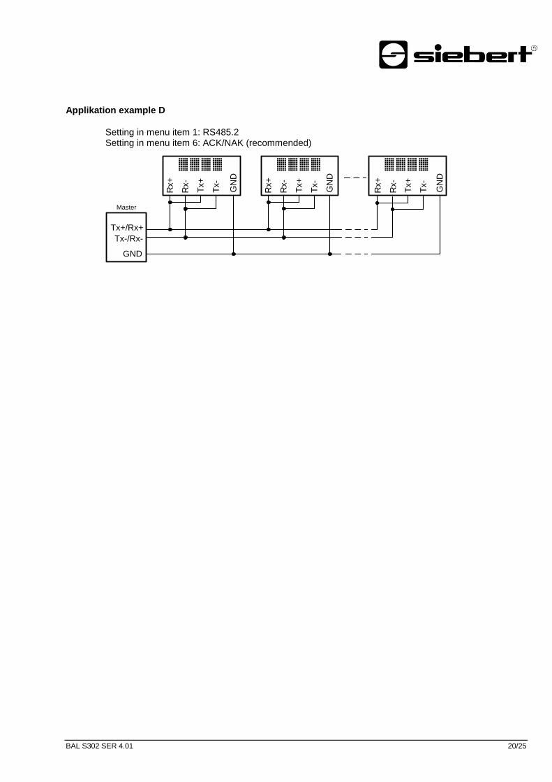
Applikation example D
Setting in menu item 1: RS485.2 Setting in menu item 6: ACK/NAK (recommended)
Master
Rx+
Rx-
Tx+
Tx-
GN
D
ABCDR
x+
Rx-
Tx+
Tx-
GN
D
ABCD
Rx+
Rx-
Tx+
Tx-
GN
D
ABCD
Tx+/Rx+
Tx-/Rx-
GND
Pos: 57 /Si ebert /Seitenumbr uch @ 0\mod_1314194553878_0.docx @ 150 @ @ 1

BAL S302 SER 4.01 21/25
Pos : 58 /Si ebert /Bedi enungsanlei tungen/Seri e S302/SX302/Technische D aten/Ü BS Technische Daten @ 0\mod_1314712092954_48.docx @ 354 @ 1 @ 1
8 Technical data
Pos: 59 /Si ebert /Bedi enungsanlei tungen/Seri e S302/SX302/Technische D aten/S302 Ger äteausführung @ 0\mod_1314709982956_48.docx @ 337 @ 2 @ 1
Unit properties
The model designation is structured as follows:
S302 – / / – / –
: : : : : : : : : : : : :
No dimension symbol 0 : : : : : : : : : : : :
Dimension symbol F : : : : : : : : : : : :
: : : : : : : : : : : :
1 Digit 1 : : : : : : : : : : :
2 Digits 2 : : : : : : : : : : :
: : : : : : : : : : :
8 Digits 8 : : : : : : : : : : :
: : : : : : : : : : :
Character height 25 mm 0 3 : : : : : : : : :
Character height 57 mm 0 6 : : : : : : : : :
Character height 100 mm 1 0 : : : : : : : : :
Character height 160 mm 1 6 : : : : : : : : :
Character height 250 mm 2 5 : : : : : : : : :
: : : : : : : : :
LED Standard 0 : : : : : : : :
LED, SMD technology : : : : : : : :
LED for outdoor use 2 : : : : : : : :
LRD® 4 : : : : : : : :
: : : : : : : :
Character color red R : : : : : : :
Character color green G : : : : : : :
Character color white W : : : : : : :
Character color red/green/orange switchable M : : : : : : :
: : : : : : :
Display readable on one side 1 : : : : : :
Display readable on both sides 2 : : : : : :
: : : : : :
Steel sheet housing, coated 0 : : : : :
Steel sheet housing, bilayer painting 1 : : : : :
Stainless steel housing V2A, coated 2 : : : : :
Stainless steel housing V2A, brushed 3 : : : : :
Stainless steel housing V4A, brushed 5 : : : : :
: : : : :
Protection type IP54 0 : : : :
Protection type IP65 1 : : : :
Protection type IP54 with climate adjustment 2 : : : :
Protection type IP54 with climate adjustment and heating 4 : : : :
: : : :
Wall mounting, cable entry point from the bottom 0 : : :
Wall mounting, cable entry point from the top 1 : : :
Hanging installation, cable entry point from the bottom 2 : : :
Hanging installation, cable entry point from the top 3 : : :
Wall mounting and hanging installation, cable entry point from the bottom 4 : : :
Wall mounting and hanging installation, cable entry point from the top 5 : : :
: : :
Power supply 230 V AC ±15 %, 50 Hz A : :
Power supply 24 V DC ±15 % B : :
Power supply 115 V AC ±15 %, 60 Hz C : :
: :
Interface x x

BAL S302 SER 4.01 22/25
Pos: 60 /Si ebert /Bedi enungsanlei tungen/Seri e S302/SX302/Technische D aten/S302 M axi mal e Leis tungsaufnahme @ 0\mod_1314971476367_48.docx @ 777 @ 2 @ 1
Max. power consumption
Units with one-sided display [VA]1) Units with double-sided display [VA]
1)
1 digit 1 digit
S302-x1/10/xx-1xx/xx-xx 12 (50) S302-x1/10/xx-2xx/xx-xx 16 (91)
S302-x1/16/xx-1xx/xx-xx 22 (50) S302-x1/16/xx-2xx/xx-xx 35 (91)
S302-x1/25/xx-1xx/xx-xx 26 S302-x1/25/xx-2xx/xx-xx 42
2 digits 2 digits
S302-x2/06/xx-1xx/xx-xx 12 S302-x2/06/xx-2xx/xx-xx 15
S302-x2/10/xx-1xx/xx-xx 15 (50) S302-x2/10/xx-2xx/xx-xx 21 (91)
S302-x2/16/xx-1xx/xx-xx 37 (50) S302-x2/16/xx-2xx/xx-xx 66 (91)
S302-x2/25/xx-1xx/xx-xx 46 S302-x2/25/xx-2xx/xx-xx 83
3 digits 3 digits
S302-x3/06/xx-1xx/xx-xx 13 S302-x3/06/xx-2xx/xx-xx 17
S302-x3/10/xx-1xx/xx-xx 17 (50) S302-x3/10/xx-2xx/xx-xx 26 (91)
S302-x3/16/xx-1xx/xx-xx 51 (50) S302-x3/16/xx-2xx/xx-xx 92 (91)
S302-x3/25/xx-1xx/xx-xx 63 S302-x3/25/xx-2xx/xx-xx 116
4 digits 4 digits
S302-x4/06/xx-1xx/xx-xx 14 S302-x4/06/xx-2xx/xx-xx 19
S302-x4/10/xx-1xx/xx-xx 21 (50) S302-x4/10/xx-2xx/xx-xx 33 (91)
S302-x4/16/xx-1xx/xx-xx 64 (50) S302-x4/16/xx-2xx/xx-xx 119 (91)
S302-x4/25/xx-1xx/xx-xx 79 S302-x4/25/xx-2xx/xx-xx 150
5 digits 5 digits
S302-x5/06/xx-1xx/xx-xx 15 S302-x5/06/xx-2xx/xx-xx 21
S302-x5/10/xx-1xx/xx-xx 23 (50) S302-x5/10/xx-2xx/xx-xx 38 (91)
S302-x5/16/xx-1xx/xx-xx 77 (50) S302-x5/16/xx-2xx/xx-xx 146 (91)
S302-x5/25/xx-1xx/xx-xx 96 S302-x5/25/xx-2xx/xx-xx 184
6 digits 6 digits
S302-x6/03/xx-1xx/xx-xx 16 S302-x6/03/xx-2xx/xx-xx 23
S302-x6/06/xx-1xx/xx-xx 16 S302-x6/06/xx-2xx/xx-xx 23
S302-x6/10/xx-1xx/xx-xx 26 (50) S302-x6/10/xx-2xx/xx-xx 43 (91)
S302-x6/16/xx-1xx/xx-xx 91 (50) S302-x6/16/xx-2xx/xx-xx 173 (91)
S302-x6/25/xx-1xx/xx-xx 113 S302-x6/25/xx-2xx/xx-xx 217
7 digits 7 digits
S302-x7/06/xx-1xx/xx-xx 17 S302-x7/06/xx-2xx/xx-xx 25
S302-x7/10/xx-1xx/xx-xx 30 (50) S302-x7/10/xx-2xx/xx-xx 51 (91)
S302-x7/16/xx-1xx/xx-xx 104 (50) S302-x7/16/xx-2xx/xx-xx 200 (91)
S302-x7/25/xx-1xx/xx-xx 130 S302-x7/25/xx-2xx/xx-xx 250
8 digits 8 digits
S302-x8/06/xx-1xx/xx-xx 18 S302-x8/06/xx-2xx/xx-xx 27
S302-x8/10/xx-1xx/xx-xx 32 (50) S302-x8/10/xx-2xx/xx-xx 55 (91)
1) The values given are approximate values. For units with built-in heating, the values for power consumption specified in the
table increase by approx. 10 – 100 VA (exact values on request), depending on the unit size. ( ) Values in parentheses are valid for LRD
® versions.
The power consumption for the unit version model S302-xx/xx/0x-xxx/xx-xx is also valid for the unit version S302-xx/xx/2x-xxx/xx-xx (LEDs for external use).
Pos: 61 /Si ebert /Bedi enungsanlei tungen/Seri e S302/SX302/Technische D aten/S302 Schaltausgang AN A,C AN,D VN,ETH,IBS,MDB, MDB TCP, PFN, PFN IRT,SER,TMR,WTS,ZLR @ 0\mod_1315485075465_48.docx @ 1492 @ 2 @ 1
Switching output
Maximum switching voltage 30 V AC/DC Maximum switching current 500 mA (ohmic load)
Pos: 62 /Si ebert /Bedi enungsanlei tungen/Technische D aten Grossanzeigen Ü ber eins timmung versch. Serien/Schr aubkl emmen S302 SX502 @ 0\mod_1315485201477_48.docx @ 1498 @ 2 @ 1
Screw-type terminals
Control computer Capacity of terminals 0,14…1,5 mm² Power supply Capacity of terminals 0,2…4 mm²
Pos: 63 /Si ebert /Bedi enungsanlei tungen/Technische D aten Grossanzeigen Ü ber eins timmung versch. Serien/Gehäusefarben S302 SX502 @ 0\mod_1315485236449_48.docx @ 1504 @ 2 @ 1
Housing colors
Case front RAL 5002 ultramarine Case rear part RAL 7035 light grey
Pos: 64 /Si ebert /Bedi enungsanlei tungen/Seri e S302/SX302/Technische D aten/S302 Fr ontschei be @ 0\mod_1315485269818_48.docx @ 1516 @ 2 @ 1

BAL S302 SER 4.01 23/25
Front frame
S302-xx/xx/xR-xxx/xx-xx Plastic, tinted red, non-reflective S302-xx/06/xG-xxx/xx-xx Plastic, tinted green, non-reflective S302-xx/10/xG-xxx/xx-xx Plastic, tinted green, non-reflective Other model types Plastic, clear, non-reflective
Pos: 65 /Si ebert /Bedi enungsanlei tungen/Seri e S302/SX302/Technische D aten/S302 U mgebungsbedi ngung en @ 0\mod_1315485292083_48.docx @ 1522 @ 2 @ 1
Ambient conditions
Operating temperature 0…55 °C Storage temperature -30…85 °C Relative humidity max. 95 % (non-condensing)
Pos: 66 /Si ebert /Bedi enungsanlei tungen/Seri e S302/SX302/Technische D aten/S302 Abmessungen & Gewichte @ 0\mod_1314183097270_48.docx @ 92 @ 2 @ 1

BAL S302 SER 4.01 24/25
Measurements and weights
Units with one-sided display
The following figure shows unit versions S302-04/10/4x-1xx/xx-xx and S302-F3/10/4x-1xx/xx-, representing the other unit versions listed in the following table.
1 digit a [mm] b [mm] c [mm] d [mm] Ø [mm] Weight [kg] 1)
S302-01/10/xx-1xx/xx-xx 330 2) 245 110 (145) 16 7 6 (7)
2)
S302-01/16/xx-1xx/xx-xx 390 300 110 (145) 20 9 7 (9)
S302-01/25/xx-1xx/xx-xx 570 400 110 20 9 11
2 digits 1 digit + dimension symbol
S302-02/06/xx-1xx/xx-xx - 300 3) 185 110 16 7 5
3)
S302-02/10/xx-1xx/xx-xx S302-F1/10/xx-1xx/xx-xx 330 2) 245 110 (145) 16 7 6 (7)
2)
S302-02/16/xx-1xx/xx-xx S302-F1/16/xx-1xx/xx-xx 390 300 110 (145) 20 9 7 (9)
S302-02/25/xx-1xx/xx-xx S302-F1/25/xx-1xx/xx-xx 570 400 110 20 9 11
3 digit 2 digit + dimension symbol
S302-03/06/xx-1xx/xx-xx S302-F2/06/xx-1xx/xx-xx 300 3) 185 110 16 7 5
3)
S302-03/10/xx-1xx/xx-xx S302-F2/10/xx-1xx/xx-xx 480 245 110 (145) 16 7 8 (9)
S302-03/16/xx-1xx/xx-xx S302-F2/16/xx-1xx/xx-xx 670 300 110 (145) 20 9 11 (13)
S302-03/25/xx-1xx/xx-xx S302-F2/25/xx-1xx/xx-xx 1030 400 110 20 9 18
4 digit 3 digit + dimension symbol
S302-04/06/xx-1xx/xx-xx S302-F3/06/xx-1xx/xx-xx 300 3) 185 110 16 7 5
3)
S302-04/10/xx-1xx/xx-xx S302-F3/10/xx-1xx/xx-xx 480 245 110 (145) 16 7 8 (9)
S302-04/16/xx-1xx/xx-xx S302-F3/16/xx-1xx/xx-xx 670 300 110 (145) 20 9 11 (13)
S302-04/25/xx-1xx/xx-xx S302-F3/25/xx-1xx/xx-xx 1030 400 110 20 9 18
5 digit 4 digit + dimension symbol
S302-05/03/xx-1xx/xx-xx - 300 3) 185 110 16 7 5
3)
S302-05/06/xx-1xx/xx-xx S302-F4/06/xx-1xx/xx-xx 400 185 110 16 7 6
S302-05/10/xx-1xx/xx-xx S302-F4/10/xx-1xx/xx-xx 680 245 110 (145) 16 7 10 (12)
S302-05/16/xx-1xx/xx-xx S302-F4/16/xx-1xx/xx-xx 960 300 110 (145) 20 9 14 (17)
S302-05/25/xx-1xx/xx-xx S302-F4/25/xx-1xx/xx-xx 1500 400 110 20 9 24
6 digit 5 digit + dimension symbol
S302-06/03/xx-1xx/xx-xx S302-F5/03/xx-1xx/xx-xx 300 3) 185 110 16 7 5
3)
S302-06/06/xx-1xx/xx-xx S302-F5/06/xx-1xx/xx-xx 400 185 110 16 7 6
S302-06/10/xx-1xx/xx-xx S302-F5/10/xx-1xx/xx-xx 680 245 110 (145) 16 7 10 (12)
S302-06/16/xx-1xx/xx-xx S302-F5/16/xx-1xx/xx-xx 960 300 110 (145) 20 9 14 (17)
S302-06/25/xx-1xx/xx-xx S302-F5/25/xx-1xx/xx-xx 1500 400 110 20 9 24
7 digit 6 digit + dimension symbol
- S302-F6/03/xx-1xx/xx-xx 300 3) 185 110 16 7 5
3)
S302-07/06/xx-1xx/xx-xx S302-F6/06/xx-1xx/xx-xx 510 185 110 16 7 7
S302-07/10/xx-1xx/xx-xx S302-F6/10/xx-1xx/xx-xx 870 245 110 (145) 16 7 12 (14)
S302-07/16/xx-1xx/xx-xx S302-F6/16/xx-1xx/xx-xx 1100 300 110 (145) 20 9 16 (20)
S302-07/25/xx-1xx/xx-xx S302-F6/25/xx-1xx/xx-xx 1730 400 110 20 9 28
8 digit 7 digit + dimension symbol
S302-08/06/xx-1xx/xx-xx S302-F7/06/xx-1xx/xx-xx 510 185 110 32 7 7
S302-08/10/xx-1xx/xx-xx S302-F7/10/xx-1xx/xx-xx 870 245 110 (145) 32 7 12 (14)
1) The figures shown for weight are approximate.
2) Units with Profibus interface: a = 480 mm, Weight = 8 (9) kg
3) Units with Profibus interface or integrated heating: a = 400 mm, Weight = 6 kg;
Units with Profibus interface and integrated heating: a = 510 mm, Weight = 7 kg ( ) Values in round brackets are valid for LRD
® versions.

BAL S302 SER 4.01 25/25
Units with double-sided display
The following figure shows unit versions S302-04/10/4x-2xx/xx-xx and S302-F3/10/4x-2xx/xx-, representing the other unit versions listed in the following table.
1 digit a [mm] b [mm] c [mm] Weight [kg] 1)
S302-01/10/xx-2xx/xx-xx 330 2) 245 170 (240) 9 (11)
2)
S302-01/16/xx-2xx/xx-xx 390 300 170 (240) 11 (12)
S302-01/25/xx-2xx/xx-xx 570 400 170 17
2 digit 1 digit + dimension symbol
S302-02/06/xx-2xx/xx-xx - 300 3) 185 170 7
3)
S302-02/10/xx-2xx/xx-xx S302-F1/10/xx-2xx/xx-xx 330 2) 245 170 (240) 9 (9)
2)
S302-02/16/xx-2xx/xx-xx S302-F1/16/xx-2xx/xx-xx 390 300 170 (240) 11 (11)
S302-02/25/xx-2xx/xx-xx S302-F1/25/xx-2xx/xx-xx 570 400 170 17
3 digit 2 digit + dimension symbol
S302-03/06/xx-2xx/xx-xx S302-F2/06/xx-2xx/xx-xx 300 3) 185 170 7
3)
S302-03/10/xx-2xx/xx-xx S302-F2/10/xx-2xx/xx-xx 480 245 170 (240) 12 (15)
S302-03/16/xx-2xx/xx-xx S302-F2/16/xx-2xx/xx-xx 670 300 170 (240) 17 (19)
S302-03/25/xx-2xx/xx-xx S302-F2/25/xx-2xx/xx-xx 1030 400 170 27
4 digit 3 digit + dimension symbol
S302-04/06/xx-2xx/xx-xx S302-F3/06/xx-2xx/xx-xx 300 3) 185 170 7
3)
S302-04/10/xx-2xx/xx-xx S302-F3/10/xx-2xx/xx-xx 480 245 170 (240) 12 (15)
S302-04/16/xx-2xx/xx-xx S302-F3/16/xx-2xx/xx-xx 670 300 170 (240) 17 (19)
S302-04/25/xx-2xx/xx-xx S302-F3/25/xx-2xx/xx-xx 1030 400 170 27
5 digit 4 digit + dimension symbol
S302-05/03/xx-2xx/xx-xx - 300 3) 185 170 7
3)
S302-05/06/xx-2xx/xx-xx S302-F4/06/xx-2xx/xx-xx 400 185 170 8
S302-05/10/xx-2xx/xx-xx S302-F4/10/xx-2xx/xx-xx 680 245 170 (240) 15 (19)
S302-05/16/xx-2xx/xx-xx S302-F4/16/xx-2xx/xx-xx 960 300 170 (240) 21 (26)
S302-05/25/xx-2xx/xx-xx S302-F4/25/xx-2xx/xx-xx 1500 400 170 36
6 digit 5 digit + dimension symbol
S302-06/03/xx-2xx/xx-xx S302-F5/03/xx-2xx/xx-xx 300 3) 185 170 7
3)
S302-06/06/xx-2xx/xx-xx S302-F5/06/xx-2xx/xx-xx 400 185 170 8
S302-06/10/xx-2xx/xx-xx S302-F5/10/xx-2xx/xx-xx 680 245 170 (240) 15 (19)
S302-06/16/xx-2xx/xx-xx S302-F5/16/xx-2xx/xx-xx 960 300 170 (240) 21 (27)
S302-06/25/xx-2xx/xx-xx S302-F5/25/xx-2xx/xx-xx 1500 400 170 36
7 digit 6 digit + dimension symbol
- S302-F6/03/xx-2xx/xx-xx 300 3) 185 170 7
3)
S302-07/06/xx-2xx/xx-xx S302-F6/06/xx-2xx/xx-xx 510 185 170 9
S302-07/10/xx-2xx/xx-xx S302-F6/10/xx-2xx/xx-xx 870 245 170 (240) 18 (23)
S302-07/16/xx-2xx/xx-xx S302-F6/16/xx-2xx/xx-xx 1100 300 170 (240) 24 (29)
S302-07/25/xx-2xx/xx-xx S302-F6/25/xx-2xx/xx-xx 1730 400 170 42
8 digit 7 digit + dimension symbol
S302-08/06/xx-2xx/xx-xx S302-F7/06/xx-2xx/xx-xx 510 185 170 9
S302-08/10/xx-2xx/xx-xx S302-F7/10/xx-2xx/xx-xx 870 245 170 (240) 18 (23)
1) The figures shown for weight are approximate.
2) Units with Profibus interface: a = 480 mm, Weight = 12 (15) kg
3) Units with Profibus interface or integrated heating: a = 400 mm, Weight = 8 kg;
Units with Profibus interface and integrated heating: a = 510 mm, Weight = 9 kg ( ) Values in round brackets are valid for LRD
® versions.
=== Ende der Liste für Textmar ke Inhalt2 ===
Units with character height of 25 mm (S302-xx/03/xx-2xx/xx-xx) and 57 mm (S302-xx/06/xx-2xx/xx-xx) are provided with 2 eyes instead of 4.