Operating instructions RPP / RPP-A 2-jaw parallel gripper
37
Original: 27.03.2014 ___________________________________________________________________________ ID 1104573 Operating Manual RPP; RPP-A Röhm GmbH, Dillingen Works Röhmstr. 6, 89407 Dillingen/Donau, GERMANY, Tel. (49)9071/508-0 Page 1 of 37 Assembly- and Operating Instructions: 2-jaw parallel grippers, pneumatically actuated RPP/ RPP-A Description Page Comparison: RPP/ RPP-A 2 Overview: RPP/ RPP-A 4 Safety Precautions and Guidelines for Use 6 Description of the Parallel Grippers: RPP 9 Description of the Parallel Grippers: RPP-A 17 Installation, Commissioning: RPP/ RPP-A 25 Maintenance, Repair: RPP/ RPP-A 32 Accessories: RPP/ RPP-A 35 Declaration of incorporation: RPP/ RPP-A 37 Date of issue: Dillingen, 27.03.2014
Transcript of Operating instructions RPP / RPP-A 2-jaw parallel gripper
Original: 27.03.2014
___________________________________________________________________________
ID 1104573 Operating Manual RPP; RPP-A
Röhm GmbH, Dillingen Works Röhmstr. 6, 89407 Dillingen/Donau, GERMANY, Tel. (49)9071/508-0 Page 1 of 37
Assembly- and Operating Instructions:
2-jaw parallel grippers, pneumatically actuated
RPP/ RPP-A
Description Page Comparison: RPP/ RPP-A 2 Overview: RPP/ RPP-A 4 Safety Precautions and Guidelines for Use 6 Description of the Parallel Grippers: RPP 9 Description of the Parallel Grippers: RPP-A 17 Installation, Commissioning: RPP/ RPP-A 25 Maintenance, Repair: RPP/ RPP-A 32 Accessories: RPP/ RPP-A 35 Declaration of incorporation: RPP/ RPP-A 37 Date of issue: Dillingen, 27.03.2014
Comparison: RPP; RPP-A 2-jaw parallel grippers ___________________________________________________________________________
ID 1104573 Operating Manual RPP; RPP-A
Röhm GmbH, Dillingen Works Röhmstr. 6, 89407 Dillingen/Donau, GERMANY, Tel. (49)9071/508-0 Page 2 of 37
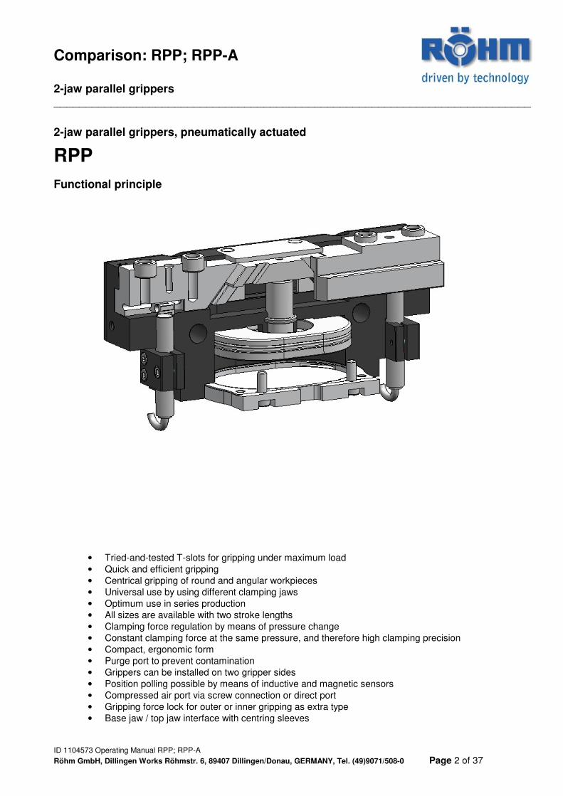
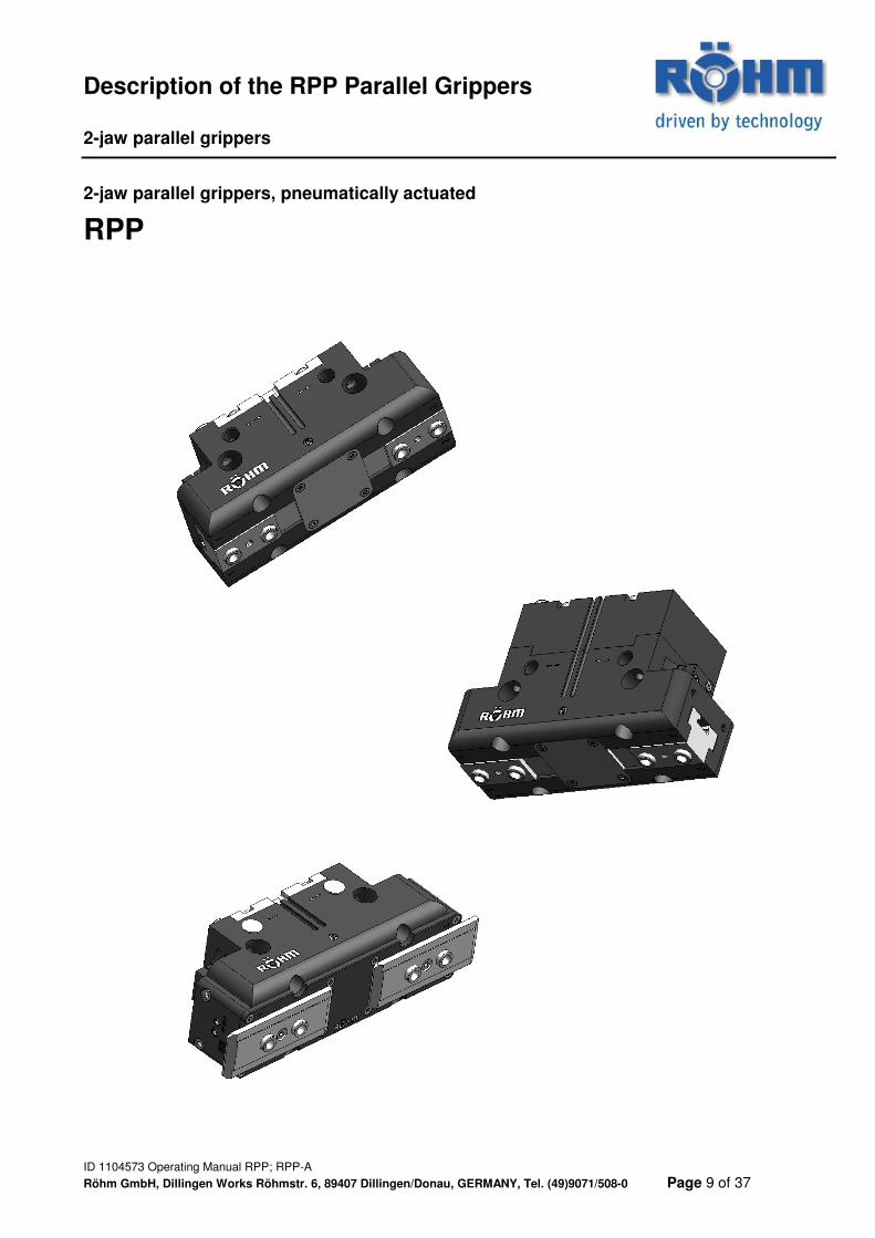
2-jaw parallel grippers, pneumatically actuated
RPP
Functional principle
• Tried-and-tested T-slots for gripping under maximum load • Quick and efficient gripping • Centrical gripping of round and angular workpieces • Universal use by using different clamping jaws • Optimum use in series production • All sizes are available with two stroke lengths • Clamping force regulation by means of pressure change • Constant clamping force at the same pressure, and therefore high clamping precision • Compact, ergonomic form • Purge port to prevent contamination • Grippers can be installed on two gripper sides • Position polling possible by means of inductive and magnetic sensors • Compressed air port via screw connection or direct port • Gripping force lock for outer or inner gripping as extra type • Base jaw / top jaw interface with centring sleeves
Comparison: RPP; RPP-A 2-jaw parallel grippers ___________________________________________________________________________
ID 1104573 Operating Manual RPP; RPP-A
Röhm GmbH, Dillingen Works Röhmstr. 6, 89407 Dillingen/Donau, GERMANY, Tel. (49)9071/508-0 Page 3 of 37
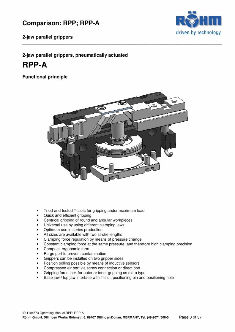
2-jaw parallel grippers, pneumatically actuated
RPP-A
Functional principle
• Tried-and-tested T-slots for gripping under maximum load • Quick and efficient gripping • Centrical gripping of round and angular workpieces • Universal use by using different clamping jaws • Optimum use in series production • All sizes are available with two stroke lengths • Clamping force regulation by means of pressure change • Constant clamping force at the same pressure, and therefore high clamping precision • Compact, ergonomic form • Purge port to prevent contamination • Grippers can be installed on two gripper sides • Position polling possible by means of inductive sensors • Compressed air port via screw connection or direct port • Gripping force lock for outer or inner gripping as extra type • Base jaw / top jaw interface with T-slot, positioning pin and positioning hole
Overview: RPP; RPP-A 2-jaw parallel grippers
ID 1104573 Operating Manual RPP; RPP-A
Röhm GmbH, Dillingen Works Röhmstr. 6, 89407 Dillingen/Donau, GERMANY, Tel. (49)9071/508-0 Page 4 of 37
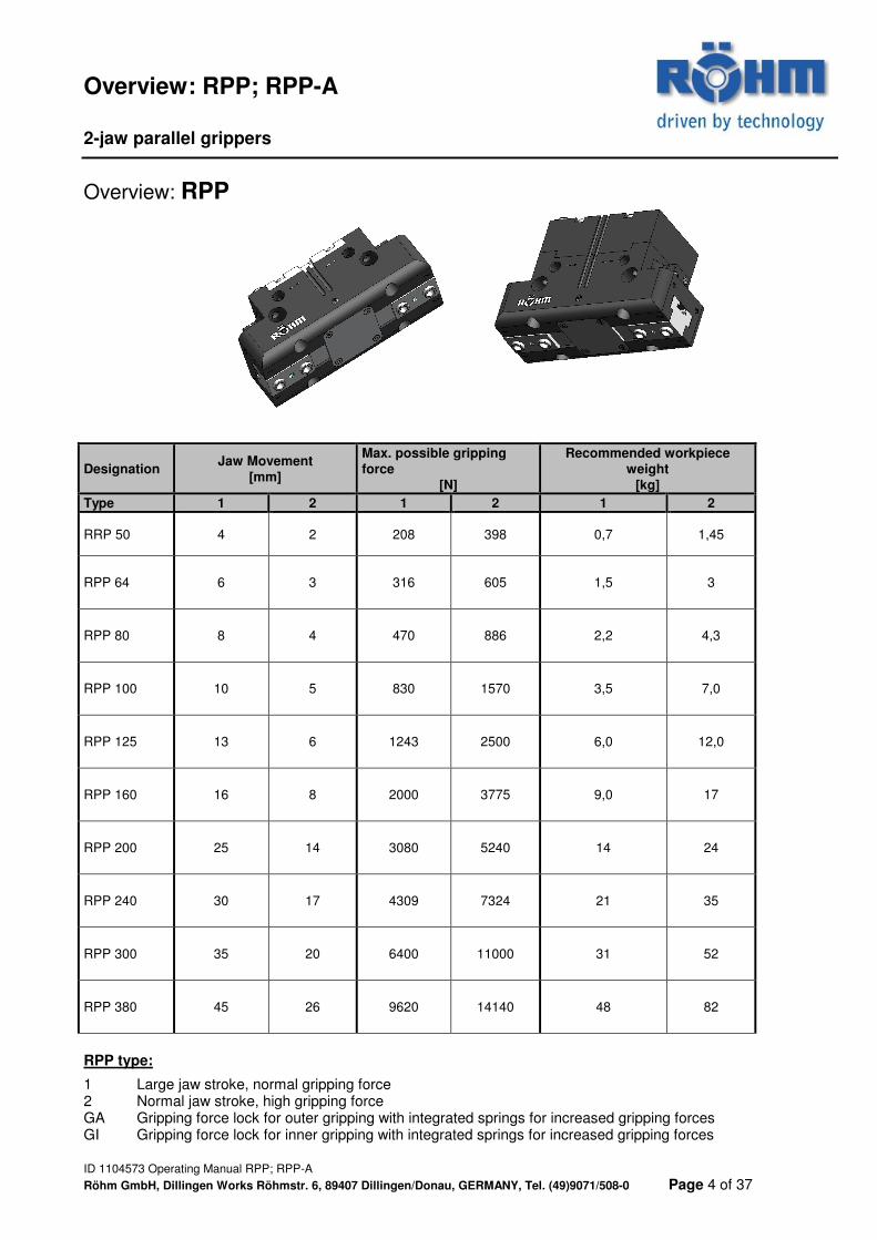
Overview: RPP
Designation Jaw Movement [mm]
Max. possible gripping force
[N]
Recommended workpiece weight
[kg] Type 1 2 1 2 1 2
RRP 50 4 2 208 398 0,7 1,45
RPP 64 6 3 316 605 1,5 3
RPP 80 8 4 470 886 2,2 4,3
RPP 100 10 5 830 1570 3,5 7,0
RPP 125 13 6 1243 2500 6,0 12,0
RPP 160 16 8 2000 3775 9,0 17
RPP 200 25 14 3080 5240 14 24
RPP 240 30 17 4309 7324 21 35
RPP 300 35 20 6400 11000 31 52
RPP 380 45 26 9620 14140 48 82
RPP type:
1 Large jaw stroke, normal gripping force 2 Normal jaw stroke, high gripping force GA Gripping force lock for outer gripping with integrated springs for increased gripping forces GI Gripping force lock for inner gripping with integrated springs for increased gripping forces
Overview: RPP; RPP-A 2-jaw parallel grippers
ID 1104573 Operating Manual RPP; RPP-A
Röhm GmbH, Dillingen Works Röhmstr. 6, 89407 Dillingen/Donau, GERMANY, Tel. (49)9071/508-0 Page 5 of 37
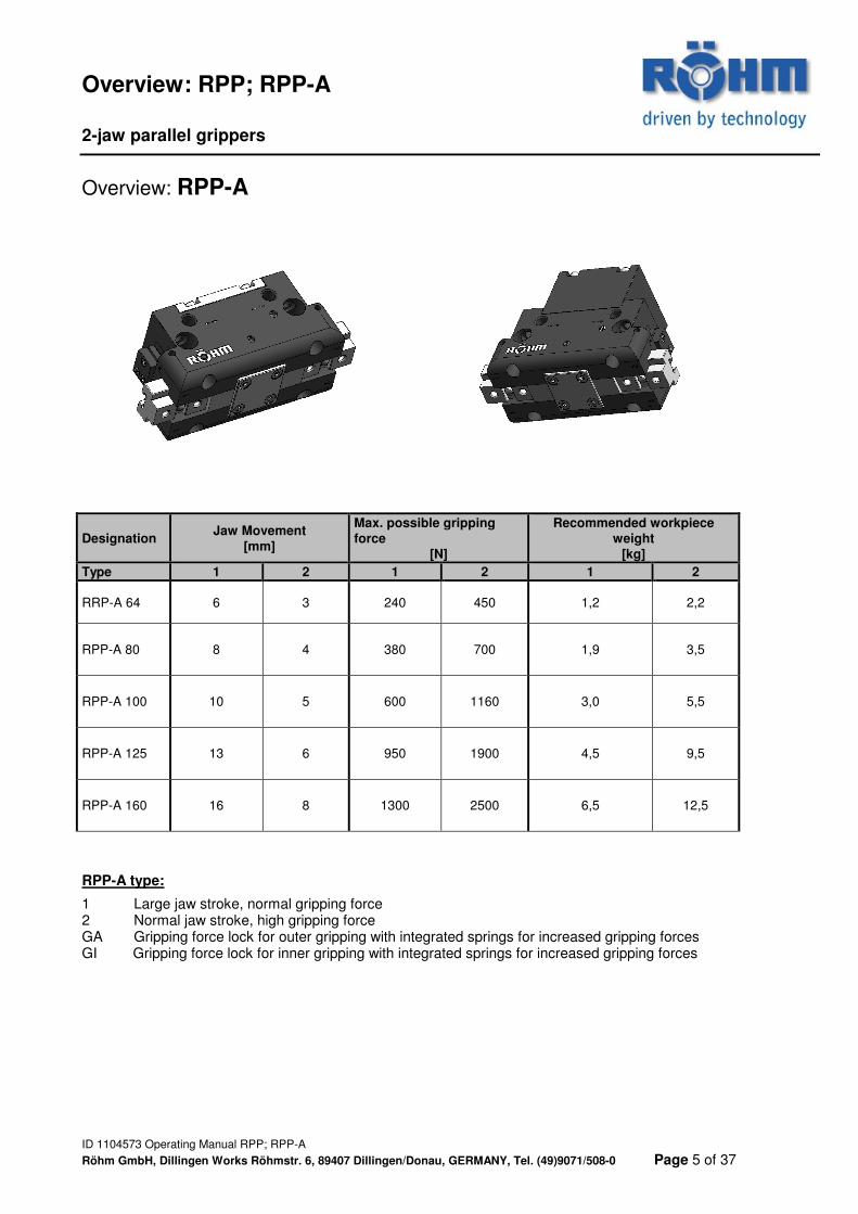
Overview: RPP-A
Designation Jaw Movement [mm]
Max. possible gripping force
[N]
Recommended workpiece weight
[kg] Type 1 2 1 2 1 2
RRP-A 64 6 3 240 450 1,2 2,2
RPP-A 80 8 4 380 700 1,9 3,5
RPP-A 100 10 5 600 1160 3,0 5,5
RPP-A 125 13 6 950 1900 4,5 9,5
RPP-A 160 16 8 1300 2500 6,5 12,5
RPP-A type:
1 Large jaw stroke, normal gripping force 2 Normal jaw stroke, high gripping force GA Gripping force lock for outer gripping with integrated springs for increased gripping forces GI Gripping force lock for inner gripping with integrated springs for increased gripping forces
Safety Precautions and Guidelines for Use 2-jaw parallel grippers
ID 1104573 Operating Manual RPP; RPP-A
Röhm GmbH, Dillingen Works Röhmstr. 6, 89407 Dillingen/Donau, GERMANY, Tel. (49)9071/508-0 Page 6 of 37
I. Qualifications of the operator Persons with no experience in working with gripping installations are exposed to particular danger due to incorrect behaviour, particularly during set-up work due to the gripping movements and forces occurring. Gripping installations may therefore only be operated, adjusted or repaired by persons specifically qualified or trained for this work, or who have many years of experience in this work. II. Risk of injury For technical reasons, this unit may consist partly of sharp-edged individual parts. Particular care must therefore be taken to avoid injury when working on these parts! 1. Installed energy accumulators Moving parts preloaded with compression springs, tension springs of other springs or with other elastic elements represent a hazard potential due to their stored energy. Underestimating this potential can result in serious injuries due to projectile-like individual parts flying around uncontrolled. This stored energy must be relieved before further work can be carried out. Gripping installations to be dismantled must therefore be examined for such potential sources of danger using the corresponding assembly drawings. If the relief of this stored energy cannot be carried out without danger, the dismantling may only be carried out by authorised personnel. 2. Calculation of the necessary gripping forces If this gripping installation is intended to hold or clamp the workpiece against machining forces exerted from the outside, the machining forces involved in a given machining process must be determined and provided with a safety allowance commensurate with the calculation method and the machining operation. The gripping installation must then be able to generate at least the gripping forces calculated in this way. 3. Use of other/further clamping inserts/workpieces The necessary minimum clamping force must always be determined when using other clamping inserts or workpieces. 1.Clamping of other/further workpieces If special clamping sets are provided for this gripping installation (jaws, clamping inserts, systems, alignment elements, position fixators, tips, etc.), only the workpieces for which the clamping sets were designed may be clamped in the intended manner using these clamping sets. If this is not observed, insufficient clamping forces or unfavourable clamping positions may result in material damage or personal injury. If further or similar workpieces are to be clamped with the same clamping set, written approval must therefore be obtained from the manufacturer. 4. Gripping force check Gripping force check (general) In accordance with standard EN 1550 § 6.2 No. d) for rotating work holding chucks which can also be applied to stationary clamping installations in this one point, static gripping force measuring instruments should be used to inspect the maintenance condition at regular intervals in accordance with the maintenance manual. This prescribes that a gripping force check should be performed after approx. 40 operating hours, irrespective of the clamping frequency. If necessary, special clamping force measuring jaws or instruments (load cells) must be used for this.
Safety Precautions and Guidelines for Use 2-jaw parallel grippers
ID 1104573 Operating Manual RPP; RPP-A
Röhm GmbH, Dillingen Works Röhmstr. 6, 89407 Dillingen/Donau, GERMANY, Tel. (49)9071/508-0 Page 7 of 37
5. Strength of the workpiece to be clamped In order to ensure reliable gripping of the workpiece with the applied load forces, the clamped material must be strong enough to withstand the gripping force. Non-metallic materials such as plastic or rubber, etc. may only be clamped after testing and under particular observation! 6. Installation and adjustment work During clamping or alignment movements, etc., short distances are travelled in short times, in some cases with high forces. The drive system provided for the gripper actuation must therefore always be switched off during installation and adjustment work. If the clamping movements are essential during set-up mode, however, then for clamping strokes longer than 4 mm - A fixed or temporarily installed workpiece holder must be installed on the device, or - An independently actuated holding device must be installed, or - A workpiece loading aid must be provided, or - The set-up operations must be performed in hydraulic, pneumatic or electric jog mode (corresponding control must be possible!). The type of this set-up aid depends fundamentally on the machine tool employed and may have to be procured separately! The machine owner must ensure that during the whole clamping process, any danger to persons from the movements of the clamping means is ruled out. For this reason, either 2-hand controls for actuation of the clamping movement or - even better - corresponding guards must be provided. 7. Tightening and replacement of bolts If bolts are replaced or loosened, faulty replacement or tightening may result in dangers for persons and materials. For this reason, the tightening torque recommended by the bolt manufacturer and corresponding to the bolt grade must always be used for al mounting bolts unless expressly specified otherwise. The following tightening torque table applies for all the standard sizes M5 - M24 for grades 8.8, 10.9 and 12.9:
Grade M5 M6 M8 M10 M12 M14 M16 M18 M20 M22 M24 8.8 5,5 9,5 23 46 80 130 190 270 380 510 670 Nm 10.9 8,1 13 33 65 110 180 270 380 530 720 960 Nm 12.9 9,5 16 39 78 140 220 330 450 640 860 1120 Nm
All figures in Nm If replacing the original bolts, always use bolt grade 12.9 in case of doubt. The grade 12.9 must always be used for the mounting bolts of clamping inserts, top jaws, fixed stops, cylinder covers and comparable elements. All mounting bolts which due to their intended use have to be frequently loosened and tightened again (e.g. due to tooling work) must be coated with lubricant (grease paste) every six months in the thread area and on the head contact surface.

Safety Precautions and Guidelines for Use 2-jaw parallel grippers
ID 1104573 Operating Manual RPP; RPP-A
Röhm GmbH, Dillingen Works Röhmstr. 6, 89407 Dillingen/Donau, GERMANY, Tel. (49)9071/508-0 Page 8 of 37
III. Environmental hazards A very wide variety of different media are currently required for lubrication, cooling, etc. during operation of a clamping or gripping installation. These are generally connected to the clamping installation by pipes or hoses. The most frequently used are hydraulic oil, lubricating oil/grease and coolants. Particular attention must be paid to these media when working with the clamping installation to ensure that they do not get into the ground or water. Caution! Environmental hazard! This applies in particular:
� During installation/removal as there may still be residues in the pipework, piston chambers or oil drain plugs, � To porous, defective or not correctly installed gaskets, � To lubricants that for design reasons escape or are slung out of the clamping installation during operation.
These escaping substances should therefore be collected and recycled or disposed of in accordance with the applicable regulations. IV. Safety engineering demands on power-actuated gripping installations:
1. The gripping installation may only be moved when the clamping pressure in the gripper has been built up and clamping can be carried out in the admissible working range.
2. Clamping may only be released when the gripping installation has come to a standstill. 3. In the event of a failure of the clamping energy, a signal must be given that immediately stops the machine. 4. In the event of a failure of the clamping energy, the workpiece must remain firmly clamped. 5. In the event of an electric power failure and return, it must not be possible for the momentary switching
position to change. V. Safety precautions:
1. Do not move parts by hand when the power supply is connected and switched on. 2. Do not reach into the open mechanical elements or between the clamping jaws. 3. Disconnect the energy supplies during installation, retooling, maintenance and adjustment
operations. 4. Carry out maintenance, retooling or attachment outside the danger zone. 5. During installation, connection, adjustment, commissioning and testing, measures must be
taken to ensure that accidental actuation of the unit by the fitter or other persons is not possible.
6. When using all handling modules, protective guards in accordance with the EC Machinery Directive must be fitted.
7. Dangers are posed by objects falling or being slung out. Measures must be taken to prevent such falling or slinging out.
8. The service and maintenance intervals must be observed. 9. Grippers which clamp under spring load or which have a gripping force lock with springs are
under spring tension. The resilient pressing star is also under spring tension. Particular care is therefore necessary during dismantling.
10. Particularly on grippers with gripping force maintenance, top jaws must be designed such that in pressure-free state, a gripper reaches one of the end positions so that no residual energy is released during changing of the top jaws. In addition, the admissible active clearances from the corresponding tables must be observed. Furthermore, the safety and accident prevention regulations applicable at the place of operation must be observed.
Description of the RPP Parallel Grippers 2-jaw parallel grippers
ID 1104573 Operating Manual RPP; RPP-A
Röhm GmbH, Dillingen Works Röhmstr. 6, 89407 Dillingen/Donau, GERMANY, Tel. (49)9071/508-0 Page 9 of 37
2-jaw parallel grippers, pneumatically actuated
RPP
Description of the RPP Parallel Grippers 2-jaw parallel grippers
ID 1104573 Operating Manual RPP; RPP-A
Röhm GmbH, Dillingen Works Röhmstr. 6, 89407 Dillingen/Donau, GERMANY, Tel. (49)9071/508-0 Page 10 of 37
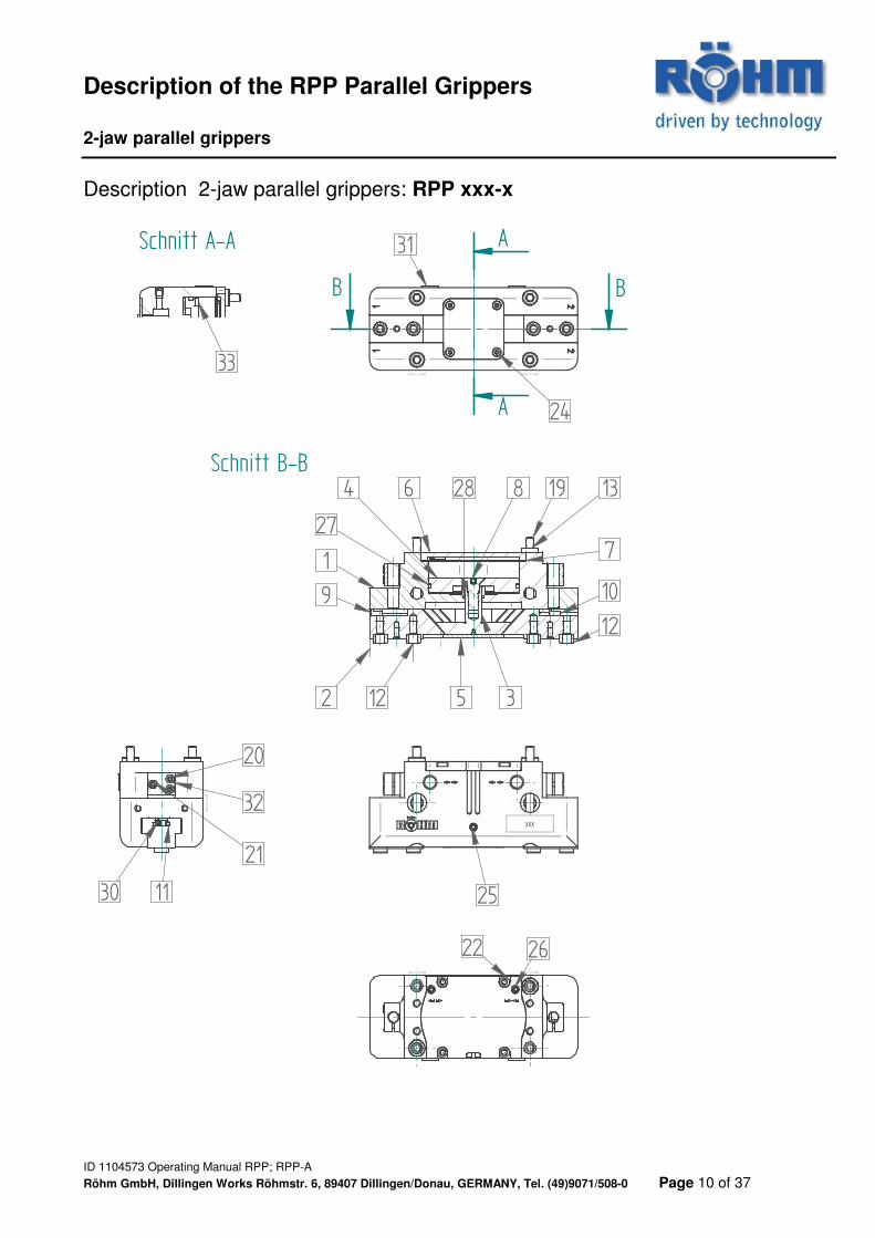
Description 2-jaw parallel grippers: RPP xxx-x
XXX
B B
Schnitt B-B
2 3
4
5
6
12
13
109
28 8
12
1
24
7
2622
25
19
20
21
32
27
30
33
11
31 A
A
Schnitt A-A
Description of the RPP Parallel Grippers 2-jaw parallel grippers
ID 1104573 Operating Manual RPP; RPP-A
Röhm GmbH, Dillingen Works Röhmstr. 6, 89407 Dillingen/Donau, GERMANY, Tel. (49)9071/508-0 Page 11 of 37
Description 2-jaw parallel grippers: RPP xxx-x
Item Designation Wear part 1 Gripper body
2 Base jaw
3 Wedge piston
4 Piston disc
5 Lower cover
6 Upper cover
7 Gasket x
8 Countersunk-head locating screw
9 Shifting block 1
10 Shifting block 2
11 Adjustment spindle
12 Centering sleeve
13 Centering sleeve
19 Mounting bolt
20 Mounting bolt
21 Mounting bolt
22 Mounting bolt
24 Mounting bolt
25 Grub screw DIN 913
26 Grub screw DIN 913
27 Quad-Ring x
28 Quad-Ring x
30 Clamping bolt
31 Protective plug
32 Sensor holder
33 Round magnet
Description of the RPP Parallel Grippers 2-jaw parallel grippers
ID 1104573 Operating Manual RPP; RPP-A
Röhm GmbH, Dillingen Works Röhmstr. 6, 89407 Dillingen/Donau, GERMANY, Tel. (49)9071/508-0 Page 12 of 37
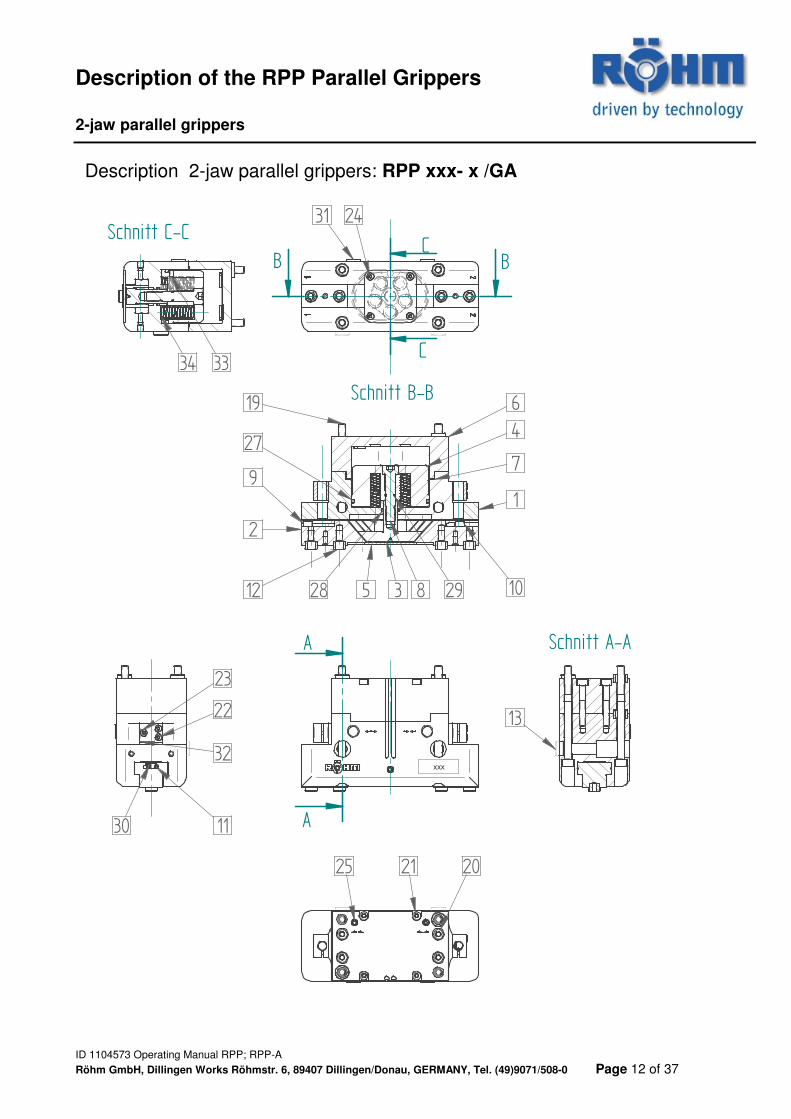
Description 2-jaw parallel grippers: RPP xxx- x /GA
XXX
A
A
Schnitt A-A
B B
Schnitt B-B
C
C
Schnitt C-C
1
2
35
7
12
9
10
6
4
8 2928
27
19
1130
32
22
23
34 33
25 21 20
13
2431

Description of the RPP Parallel Grippers 2-jaw parallel grippers
ID 1104573 Operating Manual RPP; RPP-A
Röhm GmbH, Dillingen Works Röhmstr. 6, 89407 Dillingen/Donau, GERMANY, Tel. (49)9071/508-0 Page 13 of 37
Description 2-jaw parallel grippers: RPP xxx- x /GA
Item Designation Wear part 1 Gripper body
2 Base jaw
3 Wedge piston
4 Piston
5 Lower cover
6 Spring housing
7 Gasket x
8 Locating screw
9 Shifting block 1
10 Shifting block 2
11 Adjustment spindle
12 Centering sleeve
13 Centering sleeve
19 Mounting bolt
20 Mounting bolt
21 Mounting bolt
22 Mounting bolt
23 Mounting bolt
24 Mounting bolt
25 Grub screw DIN 913
27 Quad-Ring x
28 Quad-Ring x
29 O-ring x
30 Clamping bolt
31 Protective plug
32 Sensor holder
33 Round magnet
34 Compression spring
Description of the RPP Parallel Grippers 2-jaw parallel grippers
ID 1104573 Operating Manual RPP; RPP-A
Röhm GmbH, Dillingen Works Röhmstr. 6, 89407 Dillingen/Donau, GERMANY, Tel. (49)9071/508-0 Page 14 of 37
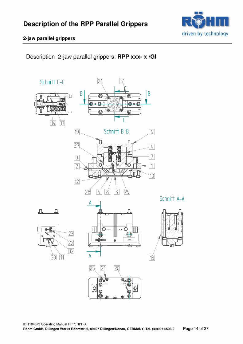
Description 2-jaw parallel grippers: RPP xxx- x /GI
XXX
A
A
Schnitt A-A
B B
Schnitt B-B
C
C
Schnitt C-C
12
35
7
12
9
10
6
4
8 2928
27
19
113032
22
23
34 33
31
25 21 20
13
24

Description of the RPP Parallel Grippers 2-jaw parallel grippers
ID 1104573 Operating Manual RPP; RPP-A
Röhm GmbH, Dillingen Works Röhmstr. 6, 89407 Dillingen/Donau, GERMANY, Tel. (49)9071/508-0 Page 15 of 37
Description 2-jaw parallel grippers: RPP xxx- x /GI
Item Designation Wear part 1 Gripper body
2 Base jaw
3 Wedge piston
4 Piston
5 Lower cover
6 Spring housing
7 Gasket x
8 Locating screw
9 Shifting block 1
10 Shifting block 2
11 Adjustment spindle
12 Centering sleeve
13 Centering sleeve
19 Mounting bolt
20 Mounting bolt
21 Mounting bolt
22 Mounting bolt
23 Mounting bolt
24 Mounting bolt
25 Grub screw DIN 913
27 Quad-Ring x
28 Quad-Ring x
29 O-ring x
30 Clamping bolt
31 Protective plug
32 Sensor holder
33 Round magnet
34 Compression spring
Description of the RPP Parallel Grippers 2-jaw parallel grippers
ID 1104573 Operating Manual RPP; RPP-A
Röhm GmbH, Dillingen Works Röhmstr. 6, 89407 Dillingen/Donau, GERMANY, Tel. (49)9071/508-0 Page 16 of 37
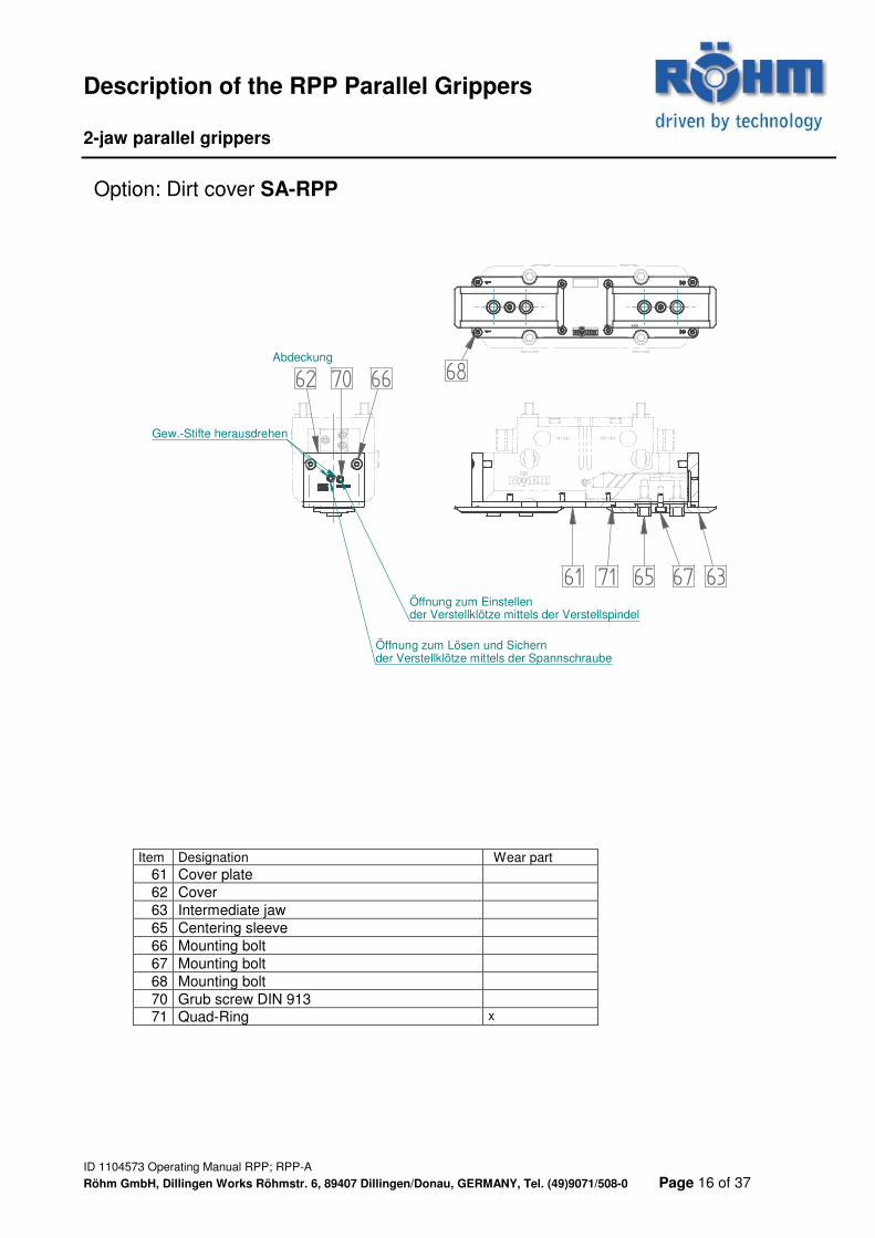
Option: Dirt cover SA-RPP
Item Designation Wear part 61 Cover plate
62 Cover
63 Intermediate jaw
65 Centering sleeve
66 Mounting bolt
67 Mounting bolt
68 Mounting bolt
70 Grub screw DIN 913
71 Quad-Ring x
XXX XXX
61 63
62
6765
66 6870
71
Gew.-Stifte herausdrehen
Abdeckung
Öffnung zum Lösen und Sichernder Verstellklötze mittels der Spannschraube
Öffnung zum Einstellender Verstellklötze mittels der Verstellspindel
Description of the RPP-A Parallel Grippers 2-jaw parallel grippers
ID 1104573 Operating Manual RPP; RPP-A
Röhm GmbH, Dillingen Works Röhmstr. 6, 89407 Dillingen/Donau, GERMANY, Tel. (49)9071/508-0 Page 17 of 37
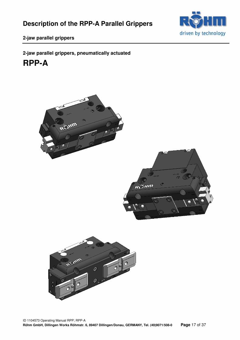
2-jaw parallel grippers, pneumatically actuated
RPP-A
Description of the RPP-A Parallel Grippers 2-jaw parallel grippers
ID 1104573 Operating Manual RPP; RPP-A
Röhm GmbH, Dillingen Works Röhmstr. 6, 89407 Dillingen/Donau, GERMANY, Tel. (49)9071/508-0 Page 18 of 37
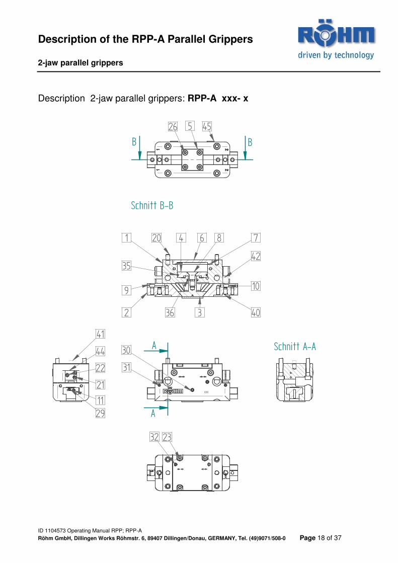
Description 2-jaw parallel grippers: RPP-A xxx- x
XXX
A
A
Schnitt A-A
B B
Schnitt B-B
1 7
109
36
35
4
526
23
11
2 3
6
29
8
42
40
31
45
32
21
22
44
20
41
30
Description of the RPP-A Parallel Grippers 2-jaw parallel grippers
ID 1104573 Operating Manual RPP; RPP-A
Röhm GmbH, Dillingen Works Röhmstr. 6, 89407 Dillingen/Donau, GERMANY, Tel. (49)9071/508-0 Page 19 of 37
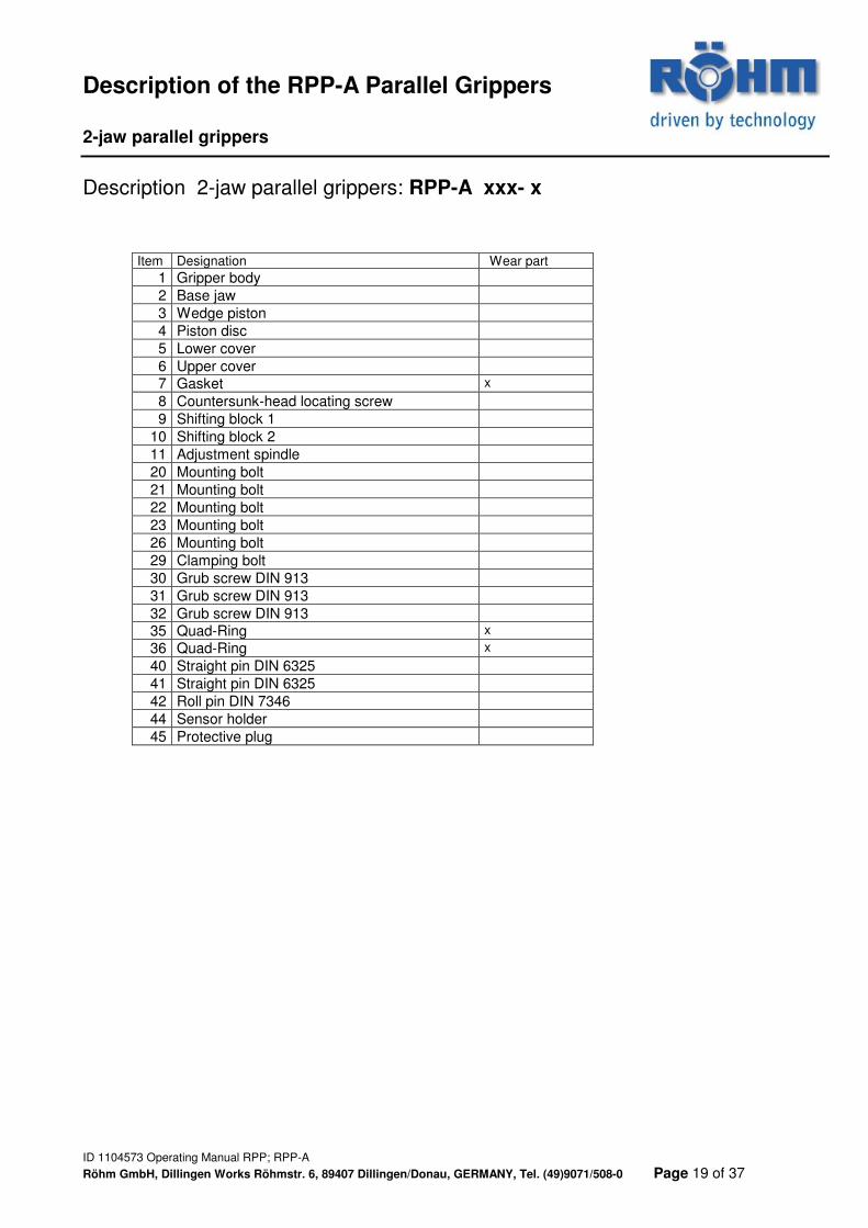
Description 2-jaw parallel grippers: RPP-A xxx- x
Item Designation Wear part 1 Gripper body
2 Base jaw
3 Wedge piston
4 Piston disc
5 Lower cover
6 Upper cover
7 Gasket x
8 Countersunk-head locating screw
9 Shifting block 1
10 Shifting block 2
11 Adjustment spindle
20 Mounting bolt
21 Mounting bolt
22 Mounting bolt
23 Mounting bolt
26 Mounting bolt
29 Clamping bolt
30 Grub screw DIN 913
31 Grub screw DIN 913
32 Grub screw DIN 913
35 Quad-Ring x
36 Quad-Ring x
40 Straight pin DIN 6325
41 Straight pin DIN 6325
42 Roll pin DIN 7346
44 Sensor holder
45 Protective plug
Description of the RPP-A Parallel Grippers 2-jaw parallel grippers
ID 1104573 Operating Manual RPP; RPP-A
Röhm GmbH, Dillingen Works Röhmstr. 6, 89407 Dillingen/Donau, GERMANY, Tel. (49)9071/508-0 Page 20 of 37
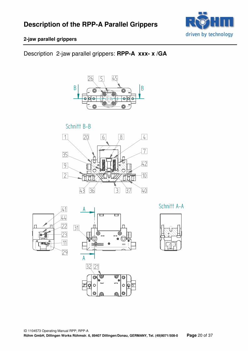
Description 2-jaw parallel grippers: RPP-A xxx- x /GA
XXX
A
A
Schnitt A-A
B B
Schnitt B-B
32 21
455
41
22
29
2
11
10
40
9
1
36
35
20
26
3
6 8
37
4
7
23
42
31
44
43

Description of the RPP-A Parallel Grippers 2-jaw parallel grippers
ID 1104573 Operating Manual RPP; RPP-A
Röhm GmbH, Dillingen Works Röhmstr. 6, 89407 Dillingen/Donau, GERMANY, Tel. (49)9071/508-0 Page 21 of 37
Description 2-jaw parallel grippers: RPP-A xxx- x /GA
Item Designation Wear part 1 Gripper body
2 Base jaw
3 Wedge piston
4 Piston disc GA
5 Lower cover
6 Spring housing
7 Gasket x
8 Locating screw
9 Shifting block 1
10 Shifting block 2
11 Adjustment spindle
20 Mounting bolt
21 Mounting bolt
22 Mounting bolt
23 Mounting bolt
26 Mounting bolt
29 Clamping bolt
31 Grub screw DIN 913
32 Grub screw DIN 913
35 Quad-Ring x
36 Quad-Ring x
37 O-ring x
40 Straight pin DIN 6325
41 Straight pin DIN 6325
42 Roll pin DIN 7346
43 Compression spring
44 Sensor holder
45 Protective plug
Description of the RPP-A Parallel Grippers 2-jaw parallel grippers
ID 1104573 Operating Manual RPP; RPP-A
Röhm GmbH, Dillingen Works Röhmstr. 6, 89407 Dillingen/Donau, GERMANY, Tel. (49)9071/508-0 Page 22 of 37
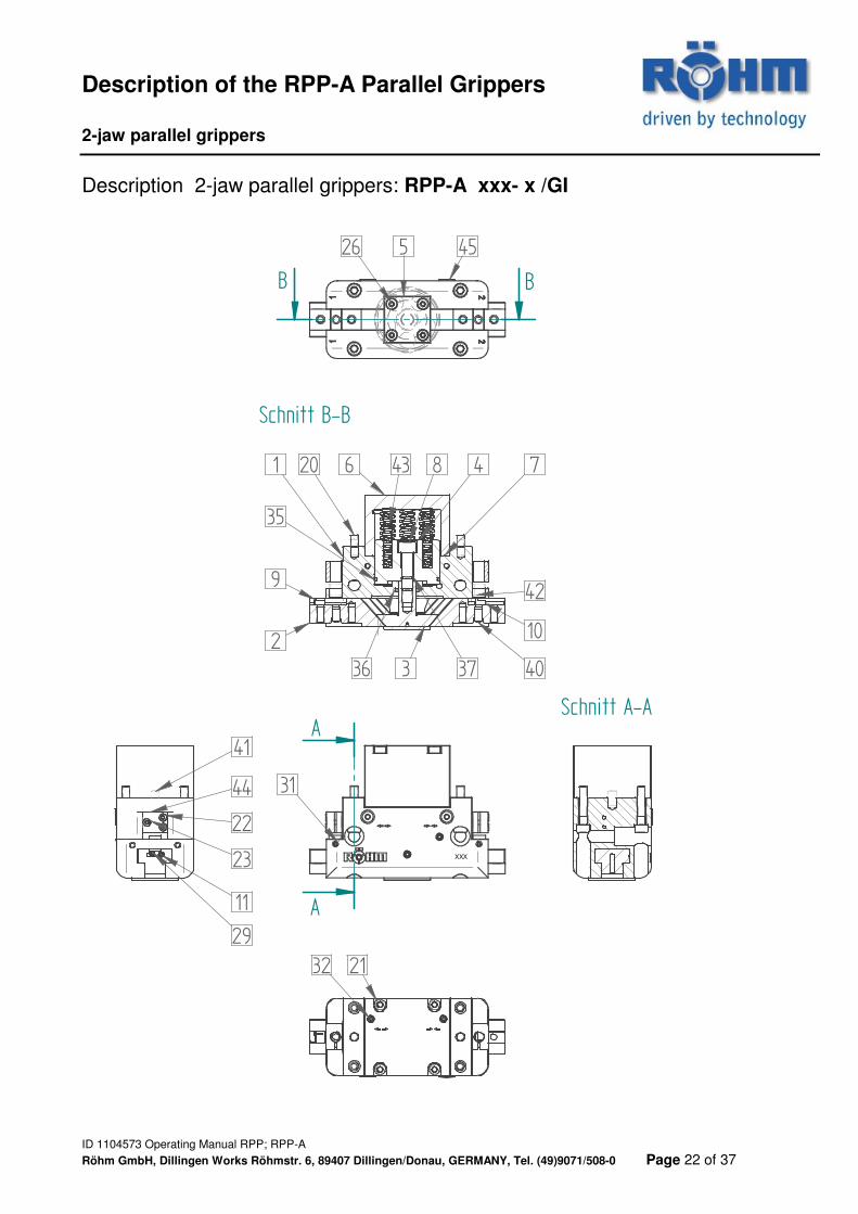
Description 2-jaw parallel grippers: RPP-A xxx- x /GI
XXX
A
A
Schnitt A-A
B B
Schnitt B-B
32 21
455
41
22
29
2
11
10
40
9
1
36
35
20 43
26
3
6 8
37
4 7
23
42
3144
Description of the RPP-A Parallel Grippers 2-jaw parallel grippers
ID 1104573 Operating Manual RPP; RPP-A
Röhm GmbH, Dillingen Works Röhmstr. 6, 89407 Dillingen/Donau, GERMANY, Tel. (49)9071/508-0 Page 23 of 37
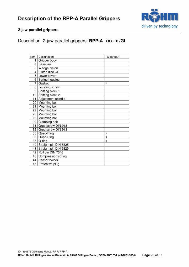
Description 2-jaw parallel grippers: RPP-A xxx- x /GI
Item Designation Wear part 1 Gripper body
2 Base jaw
3 Wedge piston
4 Piston disc GI
5 Lower cover
6 Spring housing
7 Gasket x
8 Locating screw
9 Shifting block 1
10 Shifting block 2
11 Adjustment spindle
20 Mounting bolt
21 Mounting bolt
22 Mounting bolt
23 Mounting bolt
26 Mounting bolt
29 Clamping bolt
31 Grub screw DIN 913
32 Grub screw DIN 913
35 Quad-Ring x
36 Quad-Ring x
37 O-ring x
40 Straight pin DIN 6325
41 Straight pin DIN 6325
42 Roll pin DIN 7346
43 Compression spring
44 Sensor holder
45 Protective plug
Description of the RPP-A Parallel Grippers 2-jaw parallel grippers
ID 1104573 Operating Manual RPP; RPP-A
Röhm GmbH, Dillingen Works Röhmstr. 6, 89407 Dillingen/Donau, GERMANY, Tel. (49)9071/508-0 Page 24 of 37
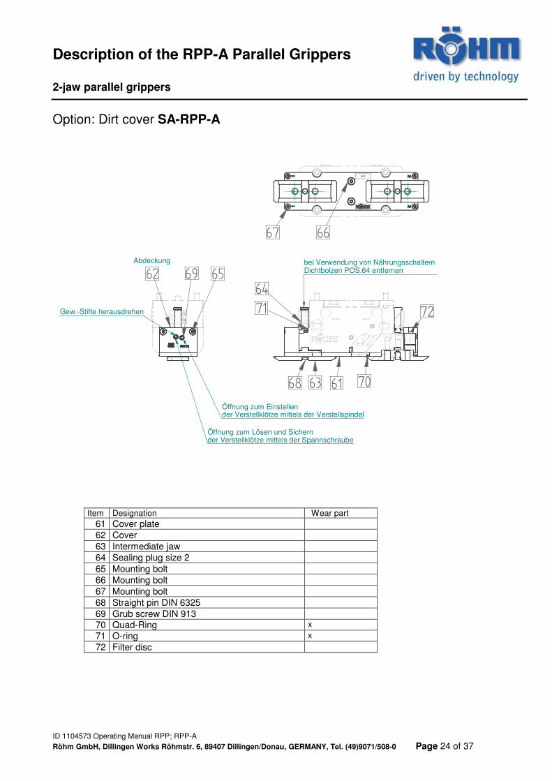
Option: Dirt cover SA-RPP-A
XXX
bei Verwendung von Nährungsschaltern Dichtbolzen POS.64 entfernen69
6462
71
68 63 61 70
72
67 66
65
Gew.-Stifte herausdrehen
Abdeckung
Öffnung zum Lösen und Sichernder Verstellklötze mittels der Spannschraube
Öffnung zum Einstellender Verstellklötze mittels der Verstellspindel
Item Designation Wear part 61 Cover plate
62 Cover
63 Intermediate jaw
64 Sealing plug size 2
65 Mounting bolt
66 Mounting bolt
67 Mounting bolt
68 Straight pin DIN 6325
69 Grub screw DIN 913
70 Quad-Ring x
71 O-ring x
72 Filter disc
Installation, Commissioning of Parallel Grippers 2-jaw parallel grippers
ID 1104573 Operating Manual RPP; RPP-A
Röhm GmbH, Dillingen Works Röhmstr. 6, 89407 Dillingen/Donau, GERMANY, Tel. (49)9071/508-0 Page 25 of 37
RPP
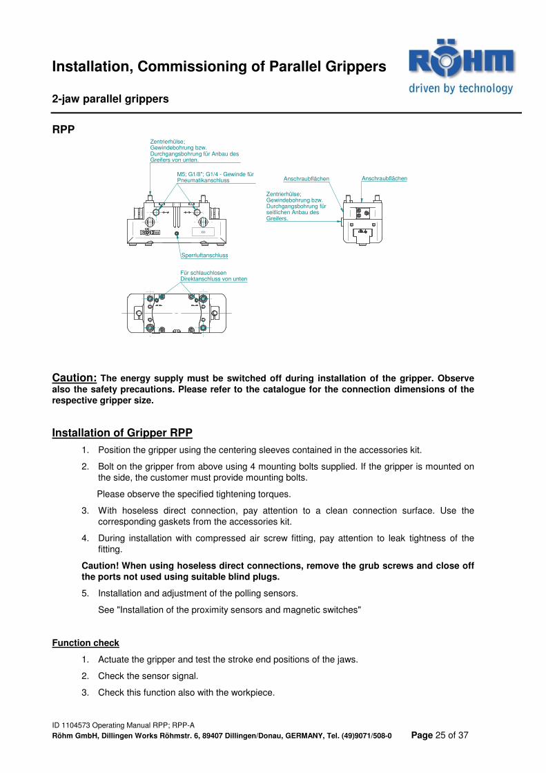
Caution: The energy supply must be switched off during installation of the gripper. Observe
also the safety precautions. Please refer to the catalogue for the connection dimensions of the
respective gripper size.
Installation of Gripper RPP
1. Position the gripper using the centering sleeves contained in the accessories kit.
2. Bolt on the gripper from above using 4 mounting bolts supplied. If the gripper is mounted on the side, the customer must provide mounting bolts.
Please observe the specified tightening torques.
3. With hoseless direct connection, pay attention to a clean connection surface. Use the corresponding gaskets from the accessories kit.
4. During installation with compressed air screw fitting, pay attention to leak tightness of the fitting.
Caution! When using hoseless direct connections, remove the grub screws and close off
the ports not used using suitable blind plugs.
5. Installation and adjustment of the polling sensors.
See "Installation of the proximity sensors and magnetic switches"
Function check
1. Actuate the gripper and test the stroke end positions of the jaws.
2. Check the sensor signal.
3. Check this function also with the workpiece.
XXX
AnschraubflächenAnschraubflächen
Für schlauchlosen Direktanschluss von unten
M5; G1/8"; G1/4 - Gewinde für Pneumatikanschluss
Zentrierhülse;Gewindebohrung bzw.Durchgangsbohrung für Anbau des Greifers von unten.
Zentrierhülse;Gewindebohrung bzw.Durchgangsbohrung für seitlichen Anbau des Greifers.
Sperrluftanschluss
Installation, Commissioning of Parallel Grippers 2-jaw parallel grippers
ID 1104573 Operating Manual RPP; RPP-A
Röhm GmbH, Dillingen Works Röhmstr. 6, 89407 Dillingen/Donau, GERMANY, Tel. (49)9071/508-0 Page 26 of 37
RPP-A
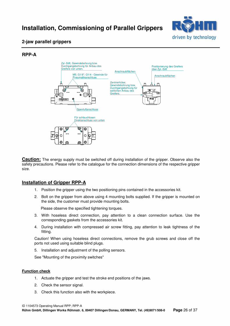
Caution: The energy supply must be switched off during installation of the gripper. Observe also the safety precautions. Please refer to the catalogue for the connection dimensions of the respective gripper size.
Installation of Gripper RPP-A
1. Position the gripper using the two positioning pins contained in the accessories kit.
2. Bolt on the gripper from above using 4 mounting bolts supplied. If the gripper is mounted on the side, the customer must provide mounting bolts.
Please observe the specified tightening torques.
3. With hoseless direct connection, pay attention to a clean connection surface. Use the corresponding gaskets from the accessories kit.
4. During installation with compressed air screw fitting, pay attention to leak tightness of the fitting.
Caution! When using hoseless direct connections, remove the grub screws and close off the ports not used using suitable blind plugs.
5. Installation and adjustment of the polling sensors.
See "Mounting of the proximity switches"
Function check
1. Actuate the gripper and test the stroke end positions of the jaws.
2. Check the sensor signal.
3. Check this function also with the workpiece.
Anschraubflächen
Anschraubflächen
Für schlauchlosen Direktanschluss von unten
M5; G1/8"; G1/4 - Gewinde für Pneumatikanschluss
Zyl.-Stift, Gewindebohrung bzw.Durchgangsbohrung für Anbau des Greifers von unten.
Zentrierhülse;Gewindebohrung bzw.Durchgangsbohrung für seitlichen Anbau des Greifers.
Sperrluftanschluss
Positionierung des Greifers über Zyl.-Stift
Installation, Commissioning of Parallel Grippers 2-jaw parallel grippers
ID 1104573 Operating Manual RPP; RPP-A
Röhm GmbH, Dillingen Works Röhmstr. 6, 89407 Dillingen/Donau, GERMANY, Tel. (49)9071/508-0 Page 27 of 37
RPP/ RPP-A
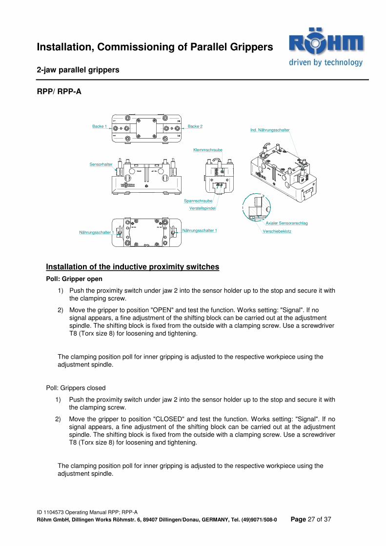
Installation of the inductive proximity switches
Poll: Gripper open
1) Push the proximity switch under jaw 2 into the sensor holder up to the stop and secure it with the clamping screw.
2) Move the gripper to position "OPEN" and test the function. Works setting: "Signal". If no signal appears, a fine adjustment of the shifting block can be carried out at the adjustment spindle. The shifting block is fixed from the outside with a clamping screw. Use a screwdriver T8 (Torx size 8) for loosening and tightening.
The clamping position poll for inner gripping is adjusted to the respective workpiece using the adjustment spindle.
Poll: Grippers closed
1) Push the proximity switch under jaw 2 into the sensor holder up to the stop and secure it with the clamping screw.
2) Move the gripper to position "CLOSED" and test the function. Works setting: "Signal". If no signal appears, a fine adjustment of the shifting block can be carried out at the adjustment spindle. The shifting block is fixed from the outside with a clamping screw. Use a screwdriver T8 (Torx size 8) for loosening and tightening.
The clamping position poll for inner gripping is adjusted to the respective workpiece using the adjustment spindle.
Ind. NährungsschalterBacke 1 Backe 2
Axialer Sensoranschlag
Sensorhalter
Klemmschraube
Spannschraube
Verstellspindel
Nährungsschalter 1 Nährungsschalter 1 Verschiebeklotz
Installation, Commissioning of Parallel Grippers 2-jaw parallel grippers
ID 1104573 Operating Manual RPP; RPP-A
Röhm GmbH, Dillingen Works Röhmstr. 6, 89407 Dillingen/Donau, GERMANY, Tel. (49)9071/508-0 Page 28 of 37
RPP/ RPP-A
XXX XXX
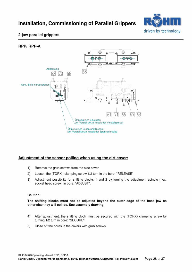
61 63
62
6765
66 6870
71
Gew.-Stifte herausdrehen
Abdeckung
Öffnung zum Lösen und Sichernder Verstellklötze mittels der Spannschraube
Öffnung zum Einstellender Verstellklötze mittels der Verstellspindel
Adjustment of the sensor polling when using the dirt cover:
1) Remove the grub screws from the side cover
2) Loosen the (TORX ) clamping screw 1/2 turn in the bore: "RELEASE"
3) Adjustment possibility for shifting blocks 1 and 2 by turning the adjustment spindle (hex. socket head screw) in bore: "ADJUST".
Caution:
The shifting blocks must not be adjusted beyond the outer edge of the base jaw as
otherwise they will collide. See assembly drawing
4) After adjustment, the shifting block must be secured with the (TORX) clamping screw by turning 1/2 turn in bore: "SECURE".
5) Close off the bores in the covers with grub screws.
Installation, Commissioning of Parallel Grippers 2-jaw parallel grippers
ID 1104573 Operating Manual RPP; RPP-A
Röhm GmbH, Dillingen Works Röhmstr. 6, 89407 Dillingen/Donau, GERMANY, Tel. (49)9071/508-0 Page 29 of 37
RPP/ RPP-A
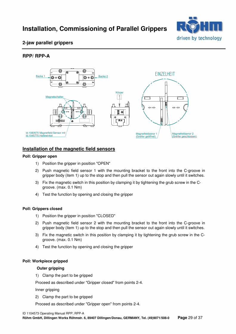
Installation of the magnetic field sensors
Poll: Gripper open
1) Position the gripper in position "OPEN"
2) Push magnetic field sensor 1 with the mounting bracket to the front into the C-groove in gripper body (item 1) up to the stop and then pull the sensor out again slowly until it switches.
3) Fix the magnetic switch in this position by clamping it by tightening the grub screw in the C-groove. (max. 0.1 Nm)
4) Test the function by opening and closing the gripper
Poll: Grippers closed
1) Position the gripper in position "CLOSED"
2) Push magnetic field sensor 2 with the mounting bracket to the front into the C-groove in gripper body (item 1) up to the stop and then pull the sensor out again slowly until it switches.
3) Fix the magnetic switch in this position by clamping it by tightening the grub screw in the C-groove. (max. 0.1 Nm)
4) Test the function by opening and closing the gripper
Poll: Workpiece gripped
Outer gripping
1) Clamp the part to be gripped
Proceed as described under "Gripper closed" from points 2-4.
Inner gripping
2) Clamp the part to be gripped
Proceed as described under "Gripper open" from points 2-4.
Backe 1 Backe 2
Magnetschalter
EINZELHEIT
Id.1083570 Magnetfeld-Sensor mitId.1045770 Haltewinkel
Magnetfeldsenor 1(Greifer geöffnet)
Magnetfeldsenor 2(Greifer geschlossen)
1Körper
Installation, Commissioning of Parallel Grippers 2-jaw parallel grippers
ID 1104573 Operating Manual RPP; RPP-A
Röhm GmbH, Dillingen Works Röhmstr. 6, 89407 Dillingen/Donau, GERMANY, Tel. (49)9071/508-0 Page 30 of 37
XXX XXX
61 63
62
6765
66 6870
71
Gew.-Stifte herausdrehen
Abdeckung
Öffnung zum Lösen und Sichernder Verstellklötze mittels der Spannschraube
Öffnung zum Einstellender Verstellklötze mittels der Verstellspindel
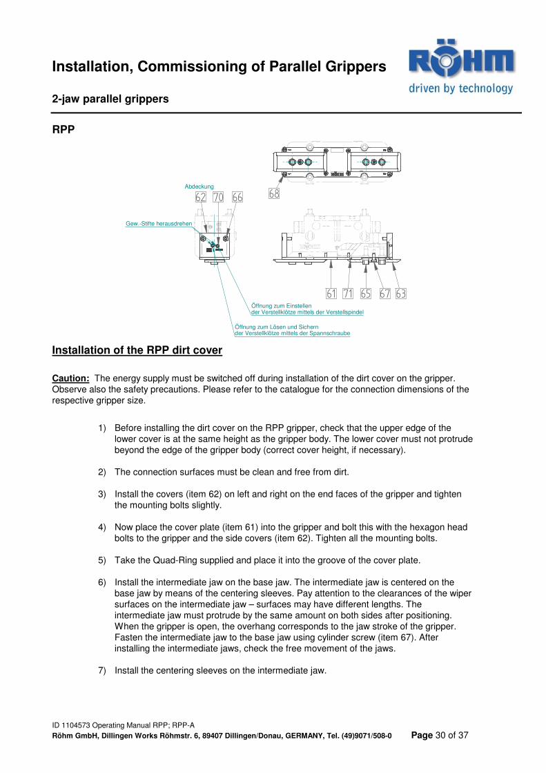
RPP
Installation of the RPP dirt cover
Caution: The energy supply must be switched off during installation of the dirt cover on the gripper. Observe also the safety precautions. Please refer to the catalogue for the connection dimensions of the respective gripper size.
1) Before installing the dirt cover on the RPP gripper, check that the upper edge of the lower cover is at the same height as the gripper body. The lower cover must not protrude beyond the edge of the gripper body (correct cover height, if necessary).
2) The connection surfaces must be clean and free from dirt.
3) Install the covers (item 62) on left and right on the end faces of the gripper and tighten the mounting bolts slightly.
4) Now place the cover plate (item 61) into the gripper and bolt this with the hexagon head bolts to the gripper and the side covers (item 62). Tighten all the mounting bolts.
5) Take the Quad-Ring supplied and place it into the groove of the cover plate.
6) Install the intermediate jaw on the base jaw. The intermediate jaw is centered on the base jaw by means of the centering sleeves. Pay attention to the clearances of the wiper surfaces on the intermediate jaw – surfaces may have different lengths. The intermediate jaw must protrude by the same amount on both sides after positioning. When the gripper is open, the overhang corresponds to the jaw stroke of the gripper. Fasten the intermediate jaw to the base jaw using cylinder screw (item 67). After installing the intermediate jaws, check the free movement of the jaws.
7) Install the centering sleeves on the intermediate jaw.
Installation, Commissioning of Parallel Grippers 2-jaw parallel grippers
ID 1104573 Operating Manual RPP; RPP-A
Röhm GmbH, Dillingen Works Röhmstr. 6, 89407 Dillingen/Donau, GERMANY, Tel. (49)9071/508-0 Page 31 of 37
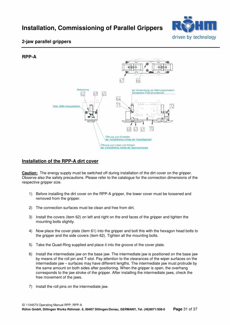
RPP-A
Installation of the RPP-A dirt cover
Caution: The energy supply must be switched off during installation of the dirt cover on the gripper. Observe also the safety precautions. Please refer to the catalogue for the connection dimensions of the respective gripper size.
1) Before installing the dirt cover on the RPP-A gripper, the lower cover must be loosened and removed from the gripper.
2) The connection surfaces must be clean and free from dirt.
3) Install the covers (item 62) on left and right on the end faces of the gripper and tighten the mounting bolts slightly.
4) Now place the cover plate (item 61) into the gripper and bolt this with the hexagon head bolts to the gripper and the side covers (item 62). Tighten all the mounting bolts.
5) Take the Quad-Ring supplied and place it into the groove of the cover plate.
6) Install the intermediate jaw on the base jaw. The intermediate jaw is positioned on the base jaw by means of the roll pin and T-slot. Pay attention to the clearances of the wiper surfaces on the intermediate jaw – surfaces may have different lengths. The intermediate jaw must protrude by the same amount on both sides after positioning. When the gripper is open, the overhang corresponds to the jaw stroke of the gripper. After installing the intermediate jaws, check the free movement of the jaws.
7) Install the roll pins on the intermediate jaw.
XXX
bei Verwendung von Nährungsschaltern Dichtbolzen POS.64 entfernen69
6462
71
68 63 61 70
72
67 66
65
Gew.-Stifte herausdrehen
Abdeckung
Öffnung zum Lösen und Sichernder Verstellklötze mittels der Spannschraube
Öffnung zum Einstellender Verstellklötze mittels der Verstellspindel
Maintenance, Repair of the Parallel Grippers 2-jaw parallel grippers
ID 1104573 Operating Manual RPP; RPP-A
Röhm GmbH, Dillingen Works Röhmstr. 6, 89407 Dillingen/Donau, GERMANY, Tel. (49)9071/508-0 Page 32 of 37
Servicing
The maintenance free operation of the gripper is ensured for a scope of up to 10 million cycles. The maintenance interval can be reduced by the following circumstances: • Operation with compressed air not compliant with DIN ISO 8573-1 quality class 4 • Polluted environment • Use other than the intended use and exceeding the gripper’s capacity • Ambient temperature higher than 60°C, lubricants harden more quickly! The gripper must be greased with the following or a demonstrably equivalent lubricant at each maintenance interval: • Klüberplex BEM 41-132 Depending on the load the guides in the body can also be lubricated via the lubricating nipples. The lubricating nipples can be installed instead of the barrier air connection. Remove the threaded pins at the barrier air connections and replace with lubricating nipples (connection threads: RPP-50 bis RPP-300 M5; RPP-380 M6).
Maintenance, Repair of the Parallel Grippers 2-jaw parallel grippers
ID 1104573 Operating Manual RPP; RPP-A
Röhm GmbH, Dillingen Works Röhmstr. 6, 89407 Dillingen/Donau, GERMANY, Tel. (49)9071/508-0 Page 33 of 37
Maintenance If the maintenance of the gripper becomes necessary (stiffness; loss of gripping force), we recommend to have the maintenance work and seal change be conducted by the Röhm GmbH Repair Service. In the event of an unauthorized disassembly and reassembly of the gripper, complications may occur, as certain work steps require special assembly equipment. Replacing the body and the base jaws The base jaws and the guides in the body are aligned. To replace these parts, send the complete gripper to the Röhm GmbH Repair Service with a repair order or order the body with base jaws as one unit. Replacing the seal It is advisable to in particular replace the dynamically loaded sealing elements and guide rings. In this case a sealing element set should always be available. The gripper is disassembled into its individual parts for maintenance and servicing, it is then checked for wear and tear, cleaned and after defective elements have been replaced the gripper is greased and reassembled. When assembling the gripper, take care to ensure that the marked parts are placed back in the intended position. Please be advised that only ORIGINAL spare parts or parts from authorized suppliers may be used. Any liability shall cease to exist for all damage caused by the use of foreign components.
Important: In order to be able to handle any orders of spare parts or
individual parts easily, the six-digit identification number engraved in the component and the manufacturing number - if available - have to be stated. The manufacturing number consists of two digits and a consecutive number, attached to the identification plate or in the direct vicinity of the identification number.
Address of the manufacturer: Company
RÖHM GmbH Werk Dillingen Röhmstr. 6 89407 Dillingen/Donau GERMANY
Maintenance, Repair of the Parallel Grippers 2-jaw parallel grippers
ID 1104573 Operating Manual RPP; RPP-A
Röhm GmbH, Dillingen Works Röhmstr. 6, 89407 Dillingen/Donau, GERMANY, Tel. (49)9071/508-0 Page 34 of 37
Dismantling and assembly of a gripper: Caution: Be sure to observe the safety precautions.
1) Disconnect the pressure lines 2) Loosen the bolts and remove the lower cover (item 5). 3) Unscrew the bolts and remove the upper cover (item 6). 4) Loosen the bolt (item 8) and remove the piston disc (item 4).
(Item 8 is secured with Loctite) 5) Press the wedge piston (item 3) up out of the gripper body (item 1). 6) Pull the base jaws (item 2) out of the gripper body (item 1). 7) Remove all gaskets 8) Clean all parts thoroughly and inspect the parts for wear
or defects. 9) Renew all gaskets The gripper is reassembled in the reverse order. Pay attention to the correct numbering and position of the components. Unless otherwise prescribed, all bolts must be secured with Loctite 222 and tightened to a torque as specified in the DIN standard (see point II/7). Type GA or GI with gripping force lock:
Caution! Particular dangers exist here! Be sure to pay attention to the assembly drawing!
Gripper body, spring housing, piston disc and piston may be under spring pressure. The spring load on the piston disc (GA type) or spring housing (GI type) must be countered by appropriate means.
Accessories (not included in scope of supply) 2-jaw parallel grippers
ID 1104573 Operating Manual RPP; RPP-A
Röhm GmbH, Dillingen Works Röhmstr. 6, 89407 Dillingen/Donau, GERMANY, Tel. (49)9071/508-0 Page 35 of 37
5M
3,5
4O
5M 3
4O
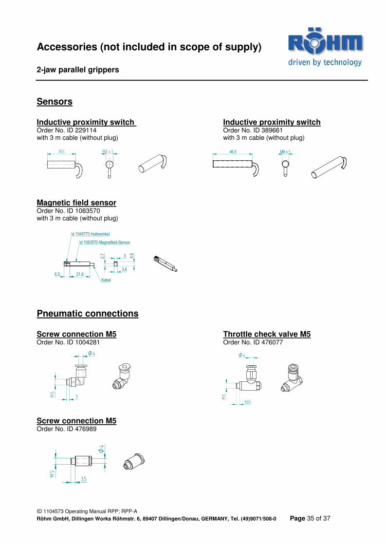
Sensors Inductive proximity switch Inductive proximity switch Order No. ID 229114 Order No. ID 389661 with 3 m cable (without plug) with 3 m cable (without plug)
Magnetic field sensor Order No. ID 1083570 with 3 m cable (without plug)
6,5 21,6
Id.1045770 Haltewinkel
Id.1083570 Magnetfeld-Sensor
Kabel
3
3,6
4,6
2,7
Pneumatic connections Screw connection M5 Throttle check valve M5 Order No. ID 1004281 Order No. ID 476077
Screw connection M5 Order No. ID 476989
M8 x 130,5
5M
3,65
4O
46,5 M8 x 1
Accessories (not included in scope of supply) 2-jaw parallel grippers
ID 1104573 Operating Manual RPP; RPP-A
Röhm GmbH, Dillingen Works Röhmstr. 6, 89407 Dillingen/Donau, GERMANY, Tel. (49)9071/508-0 Page 36 of 37
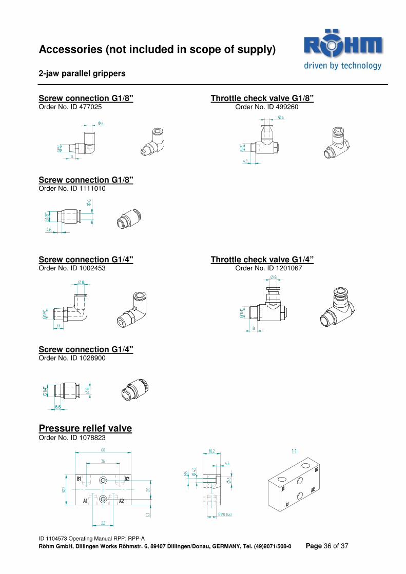
Screw connection G1/8" Throttle check valve G1/8” Order No. ID 477025 Order No. ID 499260
Screw connection G1/8" Order No. ID 1111010 Screw connection G1/4" Throttle check valve G1/4” Order No. ID 1002453 Order No. ID 1201067
G1/
4"
11
8O
8O
G1/
4"
8
Screw connection G1/4" Order No. ID 1028900
G1/
4"
6,6
8O
Pressure relief valve Order No. ID 1078823
6O
G1/8
"
8
6O
G1/8
"
4,9
6O
G1/8
"
4,6
1:1
M5 4,
5O
8O
4,4
18,2
G1/8 (4x)
60
32,2
36
22
6,1
20
2-jaw parallel grippers
ID 1104573 Operating Manual RPP; RPP-A
Röhm GmbH, Dillingen Works Röhmstr. 6, 89407 Dillingen/Donau, GERMANY, Tel. (49)9071/508-0 Page 37 of 37


![Design of Parallel-Jaw Gripper Tip Surfaces for Robust ... · resist torques due to contact and gravity [11]. Parallel-jaw grippers are widely used in the current generation of human-compliant](https://static.fdocuments.in/doc/165x107/5f0469147e708231d40dd58d/design-of-parallel-jaw-gripper-tip-surfaces-for-robust-resist-torques-due-to.jpg)