
OPERATING INSTRUCTIONS - Proline Welding Supplies - · PDF fileOPERATING INSTRUCTIONS...
32
EZIMIG 200 OPERATING INSTRUCTIONS MULTI-PROCESS MIG WELDER www.strata.co.nz 230V 50HZ SINGLE PHASE IGBT INVERTER TECHNOLOGY DIRECT CURRENT OUTPUT CONSTANT CURRENT/ VOLTAGE LIFT TIG (OPTIONAL TORCH) SPIKE/ GENERATOR SAFE 4 WHEEL DRIVE WIRE FEEDER INTELLIGENT PROTECTION SYSTEM IP23 CORROSION & SALT SPRAY RESISTANT
Transcript of OPERATING INSTRUCTIONS - Proline Welding Supplies - · PDF fileOPERATING INSTRUCTIONS...

EZIMIG 200
OPERATING INSTRUCTIONS
MULTI-PROCESS MIG WELDER
www.strata.co.nz
230V 50HZ SINGLE PHASE
IGBT INVERTER
TECHNOLOGY
DIRECT CURRENT OUTPUT
CONSTANT CURRENT/VOLTAGE
LIFT TIG(OPTIONAL
TORCH)
SPIKE/GENERATOR
SAFE
4 WHEEL DRIVE WIRE
FEEDER
INTELLIGENTPROTECTION
SYSTEM
IP23 CORROSION & SALT SPRAY
RESISTANT

2 www.strata.co.nz
EZIMIG 200
Congratulations on your new Strata product! The Strata range from Euroquip uses latest technology design and engineering to produce welding products that combine market leading value and features with durability. Designed for discerning operators who seek professional results and product quality without the price tag of a full professional setup. Design emphasis is placed on simple, functional design and operation. Strata product is subject to stringent quality control and designed and manufactured to NZ & Australian standards.
Common use of Strata products include: • LightEngineering • Automotive • Home/hobbyEngineering • Farming • IndustrialMaintenance&Repairs
Forindustrialweldingsolutions,checkouttheStratarangefromEuroquip:www.strata.co.nz
Euroquip is a market leading provider of innovative power equipment solutions to a wide range of industries across New Zealand and Australia. Key product categories are; welding equipment, air compressors, power generators and cleaning equipment.
Euroquip’s slogan is ‘empowering industries’, find out more about the advantage Euroquip brings at www.euroquip.co.nz.
Providing exceptional product support is a key component of Euroquip’s market leading customer advantage focus. As part of this program, it is required for all products to be registered with Euroquip to qualify for product support. Products not registered with Euroquip are supported by a base 12 month warranty only. Spare parts and technical support will not beavailableforanunregisteredproductoutsideofthisbasewarrantyperiod.IfaEuroquipdealer has not already registered your product, please register it online at www.euroquip.co.nz. To request a physical registration form, please download one at www.euroquip.co.nz under the ‘Contact Us’ tab.

3www.strata.co.nz
EZIMIG 200
ContentsKnowYourMachine..........................................................5
Quick Start Guide..............................................................7
Accessories & Spare Parts.................................................9
Wiring Diagram...............................................................11
Care&Maintenance.........................................................12
Welding Settings.............................................................13
Basic MIG Welding Guide..............................................14
MIGWelding Troubleshooting........................................17
EffectsofMMAWeldingVariousMetals...........................19
BasicMMAWeldingGuide..............................................20
MMAWeldingTechniques...............................................21
OtherKnowledge&Resources........................................24
MMATroubleshooting.....................................................25
Safety..............................................................................26
Warranty........................................................................31

4 www.strata.co.nz
EZIMIG 200
Ultra compact and easy to use, the EZIMIG 200 is ideal in automotive workshops for repairs and maintenance. MIG and MMA (Stick) function with hot start / anti-stick technology with spike protection, the EZIMIG 200 is built for rugged conditions in New Zealand workshops.
• IGBTInvertertechnologyforsmooth&stable welding output with increased reliability
• 4Rollgearedmetalwirefeedunitforapowerful & smooth wire feed
• MIGwaveform(Inductance)controlgivesgreater control of the arc and smoother welding results
• Damageresistantindustrialcasingwithfront panel protection
• Wireinchingandgaspurgecontrol
• Lightweight&compactdesignidealforportable applications
• Strongenvironmentalprotectionagaintmoisture, salt spray and corrosion
• Adjustablearcforce,automatichotstart& anti stick control
• Dualdigitaldisplaymetersforaccuratepre-setting and feedback of welding parameters & output
• Highquality&overspecifiedelectronic components for durability & reliability
• Temperature,voltageandcurrentsensorsfor increased reliability & safety
• Designedtoworkwithgeneratorpowersupply and protect from power surges
• 15kg(D300)spoolcapable.
• EZIMIG 200 •
MULTI-PROCESS MIG WELDER
DIMENSIONS: WEIGHT: INPUT POWER MAX. INPUT GENERATOR OUTPUT MMA O/C DUTY
STANDARDS: MMA ROD MAX WELD MIG WIRE MIG WIRE
SUPPLY: CURRENT: CAPACITY: CURRENT: VOLTAGE: CYCLE: SIZE: THICKNESS: SPOOL SIZE: SIZE:
618x240 20.5kg 230VAC15A 35A 8KVA MIG40-200A 63V MIG60%@155A EN60974-1:2012 1.6-5.0mm 10mm D200/D300 0.6-1.2 x445mm 50Hz MMA10-160A MMA60%@140A 5kg/15kg

5www.strata.co.nz
EZIMIG 200
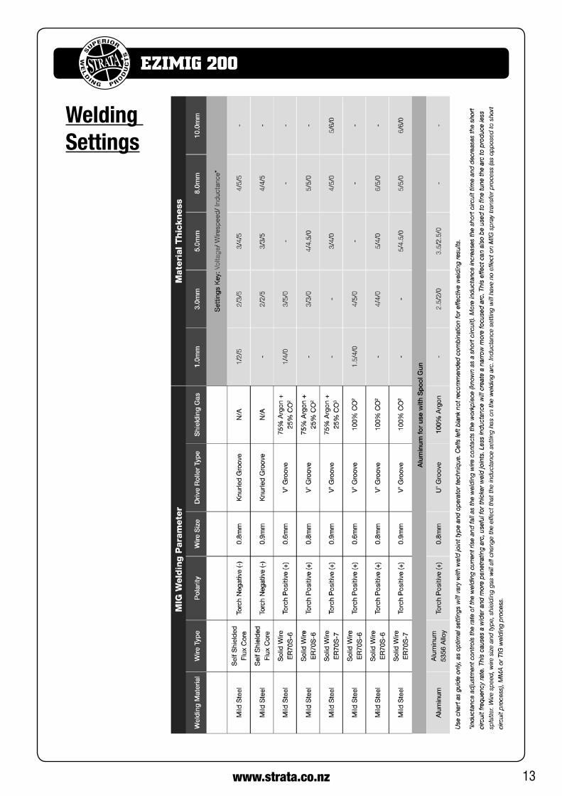
*Denotes more detailed explanation of function to follow.
1. MIGWireFeedSpeed/MMA Current Control Knob*
2. MIGVoltage/MMAArcForceAdjustmentKnob*
3. MMAModeIndicator
4. MIGModeIndicator
5. WireFeedSpeed/CurrentDisplayMeter*
6. DisplayValueIndicator-WireFeedingSpeed
7. DisplayValueIndicator-Current
8. Voltage/ArcForceDisplayMeter*
9. DisplayValueIndicator-Voltage
10.DisplayValueIndicator-ArcForce
11. PowerIndicator.LightsWhenInputPower ConnectedandMachineSwitchedOn.
12. Error/OverloadIndicator*
13. MigWaveControl/InductanceKnob*
14. WireInching/GasPurgeSwitch
15. Negative(-)WeldingPowerOutputConnection Socket.
16. MigTorchPolarityChangePowerConnection
17. Positive(+)WeldingPowerOutputConnection Socket
18. MigTorchEuroConnectSocket
Wire Feeder19. WireFeederInletGuide
20. WireFeedTensionAdjustment(2x)
21. WireFeedTensionArm(2x)
22. WireDriceRoller(2x)
23. DriveRollerRetainer(2x)
Further Controls Explained
MIG Wire Feed Speed/ MMA Current Control KnobInMIGmodethisknobsetsthewirefeedingspeedinMMAmode,setsMMAweldingcurrent
Know Your Machine10
12
15
1
2
3
45 6
78 9 11
13
14
16
17
18
19
20
21
22
23
20
MIG Voltage/ MMA Arc Force Adjustment Knob InMIGmode thisknobsets theweldingvoltage. InMMAmode,setsarcforce.
Wire Feed Speed/ Current Display MeterInMIGmode,displayswirefeedingspeedinm/minuteprior to welding, during welding displays welding cur-rentoutput.InMMAmode,displaysweldingcurrent.The display meter mode is shown by the indicator (6/7)thatislit.

6 www.strata.co.nz
EZIMIG 200
Voltage/ Arc Force Display MeterIn MIG mode, displays welding voltage. In MMAmode, displays arc force adjustment. The display me-termodeisshownbytheindicator(9/10)thatislit.
Overload/ Error IndicatorLightswhenover voltage, over current or electricaloverheating(duetoexceedingdutycycle)isdetectedand protection is activated. When protection is acti-vated, welding output will be disabled until the safety system senses the overload has reduced sufficiently andindicatorlampgoesout.Mayalsotriggerifma-chine experiences an internal power circuit failure.
When protection is activated, welding output will be disabled until the safety system senses the overload has reduced sufficiently and indicator lamp goes out. Mayalso trigger ifmachine experiences an internalpower circuit failure.
Tips & Tricks
Duty Cycle RatingWelding duty cycle is the percentage of actual weld-ing time that can occur in a ten minute cycle. E.g. 20%at160amps-thismeanstheweldercanweldat160ampsfor2minutesandthentheunitwillneedtobe rested for 8 minutes.
All duty cycle ratings are based on an ambient air temperatureof40°Cwith50%humidity,whichistheinternational standard for sucha rating. Inanenvi-ronmentwithtemperaturesexceeding40°C,thedutycyclewillbelessthanstated.Inambienttemperaturelessthan40°C,dutycycleperformancewillbehigher.
MIG Voltage & Wire Speed SettingsThe voltage control is essentially the power in the welding arc that sets the heat. The wire speed feed simply controls the rate at which the welding wire is fedintotheweldpool.Foranyvoltagepositionset-ting, there will be a specific corresponding ‘sweet spot’ in the wire feeding speed that will give the smoothest and most stable welding arc. The correct wire feeding speed for a given voltage setting is af-fected by welding wire type and size, shielding gas,
weldingmaterial and joint type. It is recommendedto set the welding voltage as desired and then slowly adjust the wire speed until the arc is smooth and sta-ble.Whenreachingthispoint,ifthepenetration/heatinputistoomuch/notenough,adjustthevoltageset-tingandrepeattheprocess.Iftheoperatorisnotableto achieve a smooth and stable arc with the desired heat input for the weld, it is likely that a change in wire sizeand/orshieldinggastypeisrequired(assumingallotherfactorsarecorrect).
Wave ControlThissettingchangestheMIGwaveformtosimulatechanging the inductance of the welding circuit. In-ductance controls the rate of the current rise and fall astheweldingwirecontactstheworkpiece(knownasashortcircuit).Moreinductanceincreasestheshortcircuit time and decreases the short circuit frequency rate. This causes a wider and more penetrating arc, useful for thicker weld joints. Less inductance willcreate a narrow more focused arc. This effect can also be used to fine tune the arc to produce less splatter.
Wire speed, wire size and type, shielding gas will all change the effect that the inductance setting has on theweldingarc. InductancechangewillhavenopracticaleffectonMIGspraytransferprocess(asop-posedtoshortcircuitprocess),MMAorTIGweldingprocess.
Arc Force ControlAnMMAweldingpowersource isdesigned topro-duceconstantoutputcurrent(CC).Thismeanswithdifferent types of electrode and arc length; the weld-ing voltage varies to keep the current constant. This can cause instability in some welding conditions as MMAweldingelectrodeswillhaveaminimumvoltagethey can operate with and still have a stable arc. Arc Forcecontrolbooststheweldingpowerifitssensesthe welding voltage is getting too low. The higher the arc force adjustment, the higher the minimum voltage that the power source will allow. This effect will also causetheweldingcurrenttoincrease.0isArcForceoff,10ismaximumArcForce.Thisispracticallyuse-ful for electrode types that have a higher operating voltage requirement or joint types that require a short arc length such as out of position welds.

7www.strata.co.nz
EZIMIG 200
Electrical ConnectionTheEZIMIG200isdesignedtooperateona15A230VACpowersupply.Ifanextensioncordmustbeused,it should be a heavy duty version with a minimum cablecoresizeof2.5mm2.ItisrecommendedtousetheEuroquipindustrialduty15Aextensionlead,partnumber;16895.
Operating EnvironmentAdequate ventilation is required to provide proper coolingfortheEZIMIG200.Ensurethatthemachineis placed on a stable level surface where clean cool aircaneasilyflowthroughtheunit.TheEZIMIG200has electrical components and control circuit boards which may be damaged by excessive dust and dirt, so a clean operating environment is important for reli-able product life.
Basic Operation
1. Fitting Wire Spool & Loading Wire Feeder
1.1 Open the wire compartment cover. Unthread the wire spool retainer. Fit the wire spool to spoolholder shaft, ensuring that the wire exits the spool towards the bottom the spool.
1.2 Set the spool brake tension by adjusting the spool tension adjustment screw before replacing the wire spool retainer. The spool brake tension should be set so that the spool can rotate freely, but does not continue to rotate once the wire feed stops. This may need to be adjusted as the wire is used up and the spool weight decreases.
WARNING! Excessive spool brake tension will cause wire feeding issues and affect welding per-formanceaswell aspremature failure/wearofwire feed components.
1.3 Feed the wire from the spool through the wiredriveinletguide(19)intothewirefeeder.
Quick Start Guide - Welder Installation1.4 Release thewire feed tensionarms (21)bypiv-
otingthewirefeedtensionadjustmentlever(20)from the vertical to the horizontal position.
1.5 Checkthewiredriveroller(22)groovesmatchtheselectedMIGwiretypeandsize.Thedriverollerwill have two different sized grooves; the size of the groove in use is stamped on the side of the drive roller.Forfluxcored‘soft’wire,suchasthatusedingaslessMIGwelding,thedriverollergroovehasa serrated profile (known as knurled). For solidcore‘hard’MIGwire,thedriverollergrooveusedhasa‘V’shapedprofile.ForAluminiumsolidcore‘soft’MIGwire,thedriverollerrequiredhasa‘u’shapedgroove.Ifnecessary,removeandchangethe drive roller by unthreading the drive roller re-tainer(23).
1.6 Once the correct drive rollers (22) are selectedand fitted, manually feed the wire through the wiredriveinletguide(19)throughthedriverollergrooves and into the brass outlet wire guide tube. Ensuring that the wire is correctly seated in the drive roller grooves, replace the wire feed tension arms(21)andlockthemintoplacebyrotatingthewirefeedtensionadjustmentlever(20)backtothevertical position.
Adjusting wire feed tension: this is accomplished by windingtheknobonthetensionadjustmentlever(20).Clockwisewill increasetension,anti-clockwisewillde-creasedrivetension.Idealtensionisaslittleaspossible,while maintaining a consistent wire feed with no drive roller slippage.
Check all other causes of excess wire feeding friction causing slippage first, such as; incorrect/ worn driveroller, worn/ damaged torch consumables, blocked/damaged torch wire guide liner, before increasing wire feed tension. There is a number scale on the tension ad-justmentlever(20)toindicatetheadjustmentposition.The higher the number indicated, the higher the tension that is set.
WARNING! Before changing the feed roller or wire spool, ensure that the mains power is switched off.

8 www.strata.co.nz
EZIMIG 200
WARNING! The use of excessive feed tension will cause rapid and premature wear of the drive roller,thesupportbearingandthedrivemotor/gearbox.
1.7 Connect theMIG Torch Euro Connector to theMIG torchEuro connection socket (18) on thefront of the machine. Secure by firmly hand tight-eningthethreadedcollarontheMIGTorchcon-nector clockwise.
1.8 CheckthatthecorrectmatchingMIGwire,driverollers(22)andMIGtorchtiparefitted.
1.9 Connect the machine to suitable mains power us-ing the mains input power lead. Switch the mains power switch to ‘on’ to power up the machine. SelecttheweldingmodebuttonsoMIGmodein-dicator(4)islit.Adjustthewirefeedspeedcon-trol(1)tomaximum.
1.10 Youarenowreadytofeedthewirethroughthetorch. With the wire feeder cover open, pull the triggeroftheMIGtorchtocheckthatthewireisfeeding smoothly through the feeder and into the torch.
1.11 With the tip removed from the torch and the torch laid out as straight as possible, activate the torch trigger until the wire feeds out through the end oftheMIGtorch.Alternatively,thewirefeedingswitchonthecontrolpanel(14)maybeusedtoactivethewirefeeder.ReplacethetipontheMIGtorch and trim off any excess wire.
2. Gasless Welding Operation
2.1 Connect the earth cable quick connector to the positiveweldingpoweroutputsocket(17).Con-nect the earth clamp to the work piece. Contact with the work piece must be firm contact with clean, bare metal, with no corrosion, paint or scale at the contact point.
2.2 ConnecttheMIGpowerconnectionlead(16)tothenegativeweldingpoweroutputsocket(15).Note if this connection is not made, there will be no electrical connection to the welding torch!
2.3 Settheweldingvoltageadjustmentknob(2),wirespeed control knob (1) andwave control knob(13)tothedesiredpositions.Youarenowreadyto weld!
3. Gas Shielded Welding Operation
3.1 Connect the earth cable quick connector to the negativeweldingpoweroutputsocket(15)Con-nect the earth clamp to the work piece. Contact with the work piece must be firm contact with clean, bare metal, with no corrosion, paint or scale at the contact point.
3.2 ConnecttheMIGpowerconnectionlead(16)tothenegativeweldingpoweroutputsocket (17).Note if this connection is not made, there will be no electrical connection to the welding torch!
3.3 Assemble the female gas quick connector to the gas line and to the regulator outlet fitting. Con-nectthegasregulatortoagascylinder(notin-cluded with machine) and connect the femalequick connector to the male gas inlet on the rear of the machine. Ensure all connections are tight. Open gas cylinder valve and adjust regulator, flow shouldbebetween10-25l/mindependingonap-plication.Re-checkregulatorflowpressureusingthegastestswitch(14)asstaticgasflowsettingmay drop once gas is flowing.
3.4 Settheweldingvoltageadjustmentknob(2),wirespeed control knob (1) andwave control knob(13)tothedesiredpositions.Youarenowreadyto weld!
Note:MIGweldingwith aluminiumprovides a uniquechallenge, due to the low column strength of the wire. This causes the wire to deform more as it is pushed through the feed mechanism and the torch wire deliv-eryliner,greatlyincreasingfriction.BecausegoodMIGwelding results are dependent on a smooth wire feed, certain changes must be made to the wire feed system to minimise friction caused issues.
Forastandard ‘push’ fed torch,a lengthofno longerthan 3m cable may be used, as well as the torch feed linermust be changed to a special Teflon/ PVC liner,rather than the conventional steel liner. Also the correct

9www.strata.co.nz
EZIMIG 200
style drive roller must be used and specific Aluminium ratedtorchcontacttip(orastandardtipinonesizeover-size,e.g.0.8mmaluminiumwire,usestandard1.0mmcontacttip).Forthisreason,itisquitecommonforop-eratorstohaveanextraMIGtorchspecificallysetupforaluminium use, if the machine is used for welding steel as well.
Withtheheavyduty4rollgearedwirefeeder,theEzi-Mig200will haveamoresteadyandconsistentwirefeed when ‘push’ feeding soft wire, than other machines with standard 2 roll wire feed units. Another option to overcome the friction issues is using a spool gun, which will give better results than a 3m push torch when weld-ing aluminium. Spool gun option is only available on the StrataAdvanceMigseries.
4. ARC/ MMA Welding Operation
4.1 Connect theearthcablequickconnector to thenegativeweldingpoweroutputsocket(15)Con-
nect the earth clamp to the work piece. Contact with the work piece must be firm contact with clean, bare metal, with no corrosion, paint or scale at the contact point.
4.2 Insertanelectrodeintotheelectrodeholderandconnect the electrode holder and work lead to the positiveweldingpoweroutputsocket(17).
Note: This polarity connection configuration is valid for mostGP(GeneralPurpose)MMAelectrodes.Therearevariancestothis.Ifindoubt,checktheelectrodespecifi-cations or consult the electrode manufacturer.
4.3 Connectthemachinetosuitablemainspowerus-ing the mains input power lead. Switch the mains power switch to ‘on’ to power up the machine. SettheweldingmodetoMMA(3).
4.4 Select the required output current (1) and arcforce(2).Youarenowreadytoweld!
Accessories & Spare PartsBinzel MT250 MIG Torch Range Parts
1. MSS2557 ShroudSpring
2. MSN2554 SwanNeckAssembly
5. UG8015 HandleCableSupportC/WBallJoint
9. B2514 ErgoHandleKitC/WLockNut
10. UG2516 Medium/LargeErgoTrigger
19. MOR1596 GunPlug‘O’Ring
20. MLN1597 LinerNut
AllproductsconformtoEN60974-7andareRoHS,REACHandWEEEcompliant

10 www.strata.co.nz
EZIMIG 200
EZIMIG 200 Consumables:
AAL3550 ArcLead16mm2Cable,35-70mmplug,4m
AEL3550 EarthLead16mm2Cable,35-70mmplug,3m
17512 15kg-5kgSpoolSpacer
17384 StrataCompactWeldingMachineTrolley
16895 15mH/D15AExtensionLead(3x2.5mm2wiring)
DW3000 AutoDarkeningHelmet,Shade9-13
DW4000 AutoDarkeningHelmet,Shade9-13 withGrindingVisor
GR101AR ArgonTwinGaugeRegulator
GR101CO2 CO2TwinGaugeRegulator
GADAR ArgonCylindertoCO2RegulatorAdaptorM/M
GADCO2 CO2CylindertoArgonRegulatorAdaptor, F/MtoF/M,inc.NylonWasher
GR119 CO²GasRegulatorHeated220volt
MT250-4E MB25MigTorch4m(Euro)
MT250-3E MB25MigTorch3m(Euro)
MT250-5E MB25MigTorch5m(Euro)
MMT2406 MigTip0.6mm(5pk)
MMT2408 MigTip0.8mm(5pk)
MMT2409 MigTip0.9mm(5pk)
MMT2410 MigTip1.0/0.8mmAlum(5pk)
MMT2412 MigTip1.2/1.0mmAlum(5pk)
MTA2581 TipAdaptorM6tips(2pk)
MCN2570 NozzleConical(2pk)
MSS2557 ShroudSpring(2pk)
MSN2554 SwanNeck
MSL1539 SteelLiner0.6-0.9mm3m
MSL1549 SteelLiner0.6-0.9mm4m
MSL1559 SteelLiner0.6x0.9mmx5m
MTL1538T TeflonLiner0.6-0.8mmx3m
MSL2432 SteelLiner1.0-1.2mmx3m
MSL2442 SteelLiner1.0-1.2mmx4m
MSL2452 SteelLiner1.0-1.2mmx5m
MTL2432T TeflonLiner1.0-1.2mmx3m
MB25KIT MIGConsumablesStarterKit-MB25.
MW5KG06 MigWire5kgSpool-0.6mm
MW5KG08 MigWire5kgSpool-0.8mm
MW5KG09 MigWire5kg-0.9mm
MW15KG08 MigWire15kgSpool-0.8mm
MW15KG09 MigWire15kgSpool-0.9mm
MW15KG10 MigWire15kgSpool-1.0mm
MW5KG08FC FluxcoredMigWire-0.8mm,4.5kg
MW5KG09FC FluxcoredMigWire-0.9mm,4.5kg
MW2KG08AL 2.2kgSpool5356-0.8mmAluminium
MW2KG10AL 2.2kgSpool5356-1.0mmAluminium
ALS3550 MMALeadSet300A3+3m1/2”DinseConnectors
S400EH 400AScrewTypeElect.Holder
S500EC Strata500aEarthClamp
CP3550 CablePlug-35-50mm³-Male
ETCPH4825 OvercordR922.5mmElectrodes(350mm)
ETCPH4832 OvercordR923.2mmElectrodes(350mm)
ETCPH4840 OvercordR924.0mmElectrodes(350mm)
ETCPH6825 Overcord2.5mmElectrodes(350mm)
ETCPH6832 Overcord3.2mmElectrodes(350mm)
ETCPH6840 Overcord4.0mmElectrodes(350mm)
ETCPH6850 Overcord5.0mmElectrodes(350mm)
ETCPH7725 Supercito2.5mmElectrodes(350mm)
ETCPH7732 Supercito3.2mmElectrodes(450mm)
ETCPH7740 Supercito4.0mmElectrodes(450mm)
ETCPH56S25 Tenax56S2.5mmElectrodes(350mm)
ETCPH56S32 Tenax56S3.2mmElectrodes(350mm)
ETCPH56S40 Tenax56S4.0mmElectrodes(450mm)
PDL15 Plug,3Pin15A250Vstraight
17835 4RollWireFeederDriveRoller0.6/0.8mm‘v’groove
17836 4RollWireFeederDriveRoller0.9/1.0mm‘v’groove
17837 4RollWireFeederDriveRoller1.0/1.2mm‘v’groove
17838 4RollWireFeederDriveRoller0.8/0.9mmfluxcored
17839 4RollWireFeederDriveRoller1.0/1.2mmfluxcored
17841 4RollWireFeederDriveRoller0.8/1.0mm‘u’groove
17843 4RollWireFeederDriveRollerRetainer
17844 GasInletQC
TheseaccessorieslistedareavailablefromyourStrataSupplier.RefertotheStrataCatalogue,yourStrataSupplier or look online at www.strata.co.nz for other accessories and consumables available.

11www.strata.co.nz
EZIMIG 200
Wiring Diagram

12 www.strata.co.nz
EZIMIG 200
Care & MaintenanceKeep your Welding Machine in Top ConditionTheEZIMIG200doesnotrequireanyspecialmain-tenance, however the user should take care of the machine as follows:
• Regularlycleantheventilationslots.
• Keepthecasingclean.
• Checkallcablesbeforeuse.
• Checkelectrodeholders,worklead/clampsand welding torches before use.
• Replacewornelectrodeholdersandearth clamps, which do not provide a good connection.
• Replacewornconsumablepartsinatimely manner.
• Useasoftclothorbrushtocleanelectrical components.
• Donotuseliquidcleaningproducts,wateror especially solvents.
• Donotusecompressedairtocleanelectricalcomponents as this can force dirt and dust further into components, causing electrical short circuits.
• Checkfordamagedparts.Donotusethewelderwith damaged parts.
• Adamagedweldermustbecarefullycheckedbya qualified person to determine that it will operate properly. Check for breakage of parts, mountings and other conditions that may affect its operation. An authorised service centre should properly repairadamagedpart.Haveyourwelderrepairedby an expert.
This appliance is manufactured in accordance with relevant safety standards. Only experts must carry out repairing of electrical appliances, otherwise considerable danger for the user may result. Use only genuine replacement parts. Do not use modified or non-genuineparts.
Storing the Welder When not in use the welder should be stored in the dryandfrost-freeenvironment.
WARNING! Before performing cleaning/main-tenance,replacingcables/connections,makesure the welding machine is switched off and disconnected from the power supply.
13www.strata.co.nz
EZIMIG 200
Welding Settings

14 www.strata.co.nz
EZIMIG 200
Basic MIG Welding GuideTwo different welding processes are covered in this section(GMAWandFCAW),withtheintentionofpro-vidingtheverybasicconceptsinMIGwelding,whereaweldinggunishandheld,andtheelectrode(weldingwire)isfedintoaweldpuddle,andthearcisshieldedbyagas(GMAW)orfluxcoredwire(FCAW).
Gas Metal ARC Welding (GMAW)This process, also known as MIG welding, CO2welding,MicroWireWelding,shortarcwelding,diptransfer welding, wire welding etc., is an electric arc welding process which fuses together the parts to be welded by heating them with an arc between a solid continuous, consumable electrode and the work.
Shielding is obtained from an externally supplied welding grade shielding gas. The process is normally applied semi automatically; however the process may be operated automatically and can be machine oper-ated. The process can be used to weld thin and fairly thicksteels,andsomenon-ferrousmetalsinallposi-tions.
GMAW Process (Fig 1-1) Shielding Gas
MoltenWeldMetalNozzleElectrode Arc
BaseMetal
SolidifiedWeldMetal
Flux Cored Arc Welding (FCAW)This is an electric arc welding process which fuses together the parts to be welded by heating them with an arc between a continuous flux filled electrode wire and the work. Shielding is obtained through decom-position of the flux within the tubular wire. Additional shielding may or may not be obtained from an ex-ternally supplied gas or gas mixture. The process is normally applied semi automatically; however the process may be applied automatically or by machine.
FCAW Process (Fig 1-2)
Nozzle(Optional)
FluxCoredElectrode
Arc
BaseMetal
SolidifiedWeldMetal
SlagMoltenSlag
MoltenMetal
Shielding Gas(Optional)
Push Vertical Drag Pull
Position of MIG Torch (Fig 1-3)
TheangleofMIGtorchtotheweldhasaneffectonthe width of the weld.
The welding gun should be held at an angle to the weldjoint.(SeeSecondaryAdjustmentVariablesbe-low).
Holdthegunsothattheweldingseamisviewedatalltimes. Always wear the welding helmet with proper filter lenses and use the proper safety equipment.
CAUTION!Do not pull the welding gun back when the arc is established. This will create excessive wire extension (stick-out) and make a very poorweld.
The electrode wire is not energized until the gun trig-ger switch is depressed. The wire may therefore be placed on the seam or joint prior to lowering the hel-met.
It is commonly used to weld large diameter elec-trodes in the flat and horizontal position and small electrode diameters in all positions. The process is used to a lesser degree for welding stainless steel and for overlay work.

15www.strata.co.nz
EZIMIG 200
(Fig 1-4) 5oto15o
LongitudinalAngle
Direction of Travel
90o TransverseAngle
(Fig 1-5)
5oto15o
LongitudinalAngle 30oto60o
TransverseAngle
Direction of Travel
Vertical Fillet Welds (Fig 1-6)
10o
LongitudinalAngle
Direction of Travel
10oto20o
LongitudinalAngle
30oto60o
TransverseAngle
30oto60o
TransverseAngle
Direction of Travel(Fig 1-7)
5oto15o
LongitudinalAngle
30oto60o
TransverseAngle
Distance from the MIG Torch Nozzle to the Work PieceTheelectrodewirestickoutfromtheMIGTorchnoz-zleshouldbebetween10mmto20mm.Thisdistance
may vary depending on the type of joint that is being welded.
Travel SpeedThe speed at which the molten pool travels influences the width of the weld and penetration of the welding run.
MIG Welding (GMAW) VariablesMost of the welding done by all processes is oncarbon steel. The items below describe the welding variables in short-arc welding of 24gauge (0.024”,0.6mm)to¼”(6.4mm)mildsheetorplate.Theap-plied techniquesandendresults in theGMAWpro-cess are controlled by these variables.
Preselected VariablesPreselected variables depend upon the type of mate-rial being welded, the thickness of the material, the welding position, the deposition rate and the mechan-ical properties.
These variables are: • Typeofelectrodewire • Sizeofelectrodewire • Typeofgas • Gasflowrate
Primary Adjustable VariablesThese control the process after preselected variables have been found. They control the penetration, bead width, bead height, arc stability, deposition rateand weld soundness.
Theyare: • ArcVoltage • Weldingcurrent(wirefeedspeed) • Travelspeed
Secondary Adjustable VariablesThese variables cause changes in primary adjustable variables which in turn cause the desired change in the bead formation. They are:
1. Stick-Out (distancebetweentheendofthecontact tube(tip)andtheendoftheelectrodewire).Maintainatabout10mmstick-out
16 www.strata.co.nz
EZIMIG 200
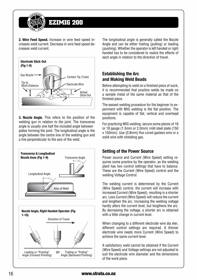
Nozzle Angle, Right Handed Operator (Fig 1-10)
Direction of Travel
Leadingor“Pushing”Angle(ForwardPointing)
Trailingor“Pulling”Angle(BackwardPointing)
90o
Establishing the Arc and Making Weld BeadsBefore attempting to weld on a finished piece of work, it is recommended that practice welds be made on a sample metal of the same material as that of the finished piece.
The easiest welding procedure for the beginner to ex-perimentwithMIGwelding is the flat position. Theequipment is capable of flat, vertical and overhead positions.
ForpracticingMIGwelding,securesomepiecesof16or18gauge(1.5mmor2.0mm)mildsteelplate(150x150mm).Use(0.8mm)fluxcoredgaslesswireorasolid wire with shielding gas.
Setting of the Power SourcePower source andCurrent (WireSpeed) setting re-quires some practice by the operator, as the welding plant has two control settings that have to balance. Theseare theCurrent(WireSpeed)controland theweldingVoltageControl.
The welding current is determined by the Current (WireSpeed) control, the currentwill increasewithincreasedCurrent(WireSpeed),resultinginashorterarc.LessCurrent(WireSpeed)willreducethecurrentandlengthenthearc.Increasingtheweldingvoltagehardly alters the current level, but lengthens the arc. By decreasing the voltage, a shorter arc is obtained with a little change in current level.
When changing to a different electrode wire dia eter, different control settings are required. A thinner electrodewireneedsmoreCurrent (WireSpeed) toachieve the same current level.
A satisfactory weld cannot be obtained if the Current (WireSpeed)andVoltagesettingsarenotadjustedtosuit the electrode wire diameter and the dimensions of the work piece.
2. Wire Feed Speed. Increase inwire feed speed in-creases weld current. Decrease in wire feed speed de-creases weld current.
Electrode Stick-Out (Fig 1-8)
Gas Nozzle
Tip toWork Distance
ContactTip(Tube)
Electrode Wire
Actual Stick-Out
3. Nozzle Angle. This refers to the position of the welding gun in relation to the joint. The transverse angle is usually one half the included angle betweenplates forming the joint. The longitudinal angle is the angle between the centre line of the welding gun and a line perpendicular to the axis of the weld.
Transverse & Longitudinal Nozzle Axes (Fig 1-9)
LongitudinalAngle
Transverse Angle
Axis of Weld
The longitudinal angle is generally called the Nozzle Angle andcanbeeither trailing (pulling)or leading(pushing).Whethertheoperatorislefthandedorrighthanded has to be considered to realize the effects of each angle in relation to the direction of travel.

17www.strata.co.nz
EZIMIG 200
MIG Welding Troubleshooting
IftheCurrent(WireSpeed)istoohighfortheweldingvoltage,“stubbing”willoccurasthewiredipsintothemolten pool and does not melt.
Welding in these conditions normally produces a poorweldduetolackoffusion.If,however,theweld-ing voltage is too high, large drops will form on the end of the wire, causing spatter. The correct setting ofvoltageandCurrent(WireSpeed)canbeseen inthe shape of the weld deposit and heard by a smooth regular arc sound.
Thegeneral approach to fixGasMetalArcWelding(GMAW)problemsistostartatthewirespoolthenworkthroughtotheMIGtorch.Therearetwomainareas where problems occur with GMAW, PorosityandInconsistentwirefeed.
When there is a gas problem the result is usually po-rosity within the weld metal. Porosity always stems from some contaminant within the molten weld pool which is in the process of escaping during solidifica-tion of the molten metal.
Contaminants range from no gas around the welding arc to dirt on the workpiece surface. Porosity can be reduced by checking the following points.
WARNING! Disengage the feed roll when testing for gas flow by ear.
Electrode Wire Size SelectionThe choice of Electrode wire size and shielding gas used depends on the following:
• Thicknessofthemetaltobewelded •Typeofjoint •Capacityofthewirefeedunitandpowersource • Theamountofpenetrationrequired • Thedepositionraterequired • Thebeadprofiledesired • Thepositionofwelding •Costofthewire
18 www.strata.co.nz
EZIMIG 200
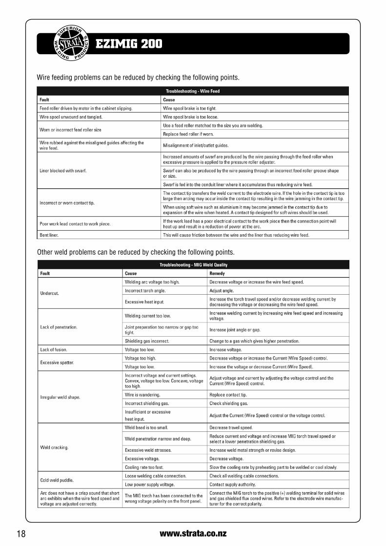
Wire feeding problems can be reduced by checking the following points.
Other weld problems can be reduced by checking the following points.
19www.strata.co.nz
EZIMIG 200
High Tensile and Alloy SteelsThe two most prominent effects of welding these steels are the formation of a hardened zone in the weld area, and, if suitable precautions are not taken,the occurrence in this zone of under-bead cracks.Hardenedzoneandunderbeadcracksintheweldareamay be reduced by using the correct electrodes, pre-heating, using higher current settings, using larger electrodes sizes, short runs for larger electrode de-posits or tempering in a furnace.
Manganese SteelsThe effect on manganese steel of slow cooling from high temperatures causes embrittlement. For thisreason it is absolutely essential to keep manganese steelcool during welding by quenching after each weld or skip welding to distribute the heat.
Cast IronMosttypesofcastiron,exceptwhiteiron,areweld-able. White iron, because of its extreme brittleness, generally cracks when attempts are made to weld it.Trouble may also be experienced when welding white-heartmalleable,duetotheporositycausedbygas held in this type of iron.
Copper and AlloysThe most important factor is the high rate of heat conductivityofcopper,makingpre-heatingofheavysections necessary to give proper fusion of weld and base metal.
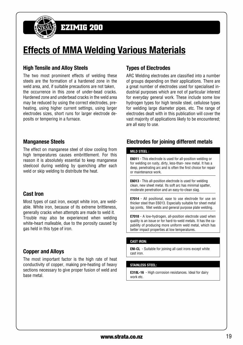
Types of ElectrodesARCWeldingelectrodesareclassifiedintoanumberof groups depending on their applications. There are a great number of electrodes used for specialised in-dustrial purposes which are not of particular interest for everyday general work. These include some low hydrogen types for high tensile steel, cellulose types for welding large diameter pipes, etc. The range of electrodes dealt with in this publication will cover the vast majority of applications likely to be encountered; are all easy to use.
MILD STEEL :
E6011-Thiselectrodeisusedforall-positionweldingor forweldingonrusty,dirty,less-than-newmetal.Ithasadeep, penetrating arc and is often the first choice for repair or maintenance work.
E6013 -Thisall-positionelectrodeisusedforweldingclean,newsheetmetal.Itssoftarchasminimalspatter,moderatepenetrationandaneasy-to-cleanslag.
E7014 - All positional, ease to use electrode for use onthickersteelthanE6013.Especiallysuitableforsheetmetallap joints, fillet welds and general purpose plate welding.
E7018-Alow-hydrogen,all-positionelectrodeusedwhenqualityisanissueorforhard-to-weldmetals.Ithastheca-pability of producing more uniform weld metal, which has better impact properties at low temperatures.
CAST IRON:
ENI-CL -Suitableforjoiningallcastironsexceptwhitecast iron.
STAINLESS STEEL:
E318L-16 -Highcorrosionresistances.Idealfordairywork etc.
Electrodes for joining different metals
Effects of MMA Welding Various Materials
20 www.strata.co.nz
EZIMIG 200
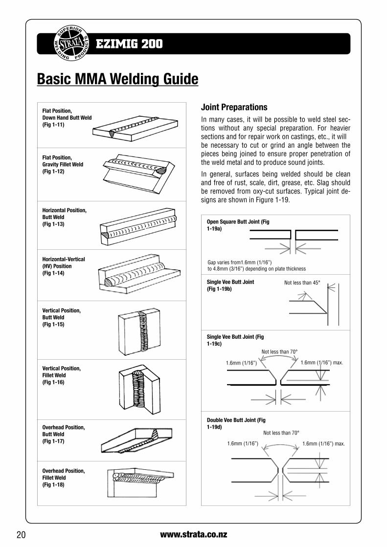
Flat Position, Down Hand Butt Weld (Fig 1-11)
Flat Position, Gravity Fillet Weld (Fig 1-12)
Horizontal Position, Butt Weld (Fig 1-13)
Horizontal-Vertical (HV) Position (Fig 1-14)
Vertical Position, Butt Weld (Fig 1-15)
Vertical Position, Fillet Weld (Fig 1-16)
Overhead Position, Butt Weld (Fig 1-17)
Overhead Position, Fillet Weld (Fig 1-18)
Joint PreparationsInmanycases, itwillbepossibletoweldsteelsec-tions without any special preparation. For heaviersections and for repair work on castings, etc., it willbe necessary to cut or grind an angle between the pieces being joined to ensure proper penetration of the weld metal and to produce sound joints.
In general, surfaces being welded should be cleanand free of rust, scale, dirt, grease, etc. Slag should beremovedfromoxy-cutsurfaces.Typical jointde-signsareshowninFigure1-19.
Open Square Butt Joint (Fig 1-19a)
Gapvariesfrom1.6mm(1/16”)to4.8mm(3/16”)dependingonplatethickness
Single Vee Butt Joint (Fig 1-19b)
Notlessthan45°
Single Vee Butt Joint (Fig 1-19c)
Notlessthan70°
1.6mm(1/16”)max.1.6mm(1/16”)
Double Vee Butt Joint (Fig 1-19d)
Notlessthan70°
1.6mm(1/16”)max.1.6mm(1/16”)
Basic MMA Welding Guide

21www.strata.co.nz
EZIMIG 200
Lap Joint (Fig 1-19e)
Fillet Joint (Fig 1-19f)
Corner Weld (Fig 1-19g)
Tee Joints (Fig 1-19h)
Edge Joint (Fig 1-19i)
Plug Welds (Fig 1-19j)
MMA Welding TechniquesA Word for BeginnersFor those who have not yet done any welding, the simplest way to commence is to run beads on a piece ofscrapplate.Usemildsteelplateabout6.0mmthickand a 3.2mm electrode.
Clean any paint, loose scale or grease off the plate and set it firmly on the work bench so that welding canbecarriedoutinthedownhandposition.MakesurethattheWorkLead/Clampismakinggoodelec-trical contact with the work, either directly or through theworktable.Forlightgaugematerial,alwaysclampthe work lead directly to the job, otherwise a poor cir-cuit will probably result.
The WelderPlace yourself in a comfortable position before begin-ning to weld. Get a seat of suitable height and do as much work as possible sitting down. Don’t hold your body tense. A taut attitude of mind and a tensed body willsoonmakeyoufeeltired.Relaxandyouwillfindthat the job becomes much easier. You can add much to your peace of mind by wearing a leather apron and gauntlets. You won’t be worrying then about being burnt or sparks setting alight to your clothes.
Place the work so that the direction of welding is across, rather than to or from, your body. The elec-trode holder lead should be clear of any obstruction so that you can move your arm freely along as the electrodeburnsdown.Iftheleadisslungoveryourshoulder, it allows greater freedom of movement and takes a lot of weight off your hand. Be sure the insula-tion on your cable and electrode holder is not faulty; otherwise you are risking an electric shock.
Striking the ArcPractice this on a piece of scrap plate before going on to more exacting work. You may at first experience difficultyduetothetipoftheelectrode“sticking”tothe work piece. This is caused by making too heavy a contact with the work and failing to withdraw the electrode quickly enough. A low amperage will accen-tuateit.Thisfreezing-onofthetipmaybeovercome

22 www.strata.co.nz
EZIMIG 200
20o
1.6mm(1/16”)
Striking an Arc(Fig 1-20)
Arc LengthThe securing of an arc length necessary to produce a neat weld soon becomes almost automatic. You will find that a long arc produces more heat.
A very long arc produces a crackling or spluttering noise and the weld metal comes across in large, ir-regular blobs. The weld bead is flattened and spatterincreases. A short arc is essential if a high quality weld is to be obtained although if it is too short there is the danger of it being blanketed by slag and the electrodetipbeingsolidifiedin.Ifthisshouldhappen,give the electrode a quick twist back over the weld to detachit.Contactor“touch-weld”electrodessuchasE7014Stickelectrodesdonotstickinthisway,andmake welding much easier.
Rate of TravelAfter the arc is struck, your next concern is to main-tain it, and this requires moving the electrode tip to-wards the molten pool at the same rate as it is melting away. At the same time, the electrode has to move along the plate to form a bead.
Making Welded JointsHavingattainedsomeskillinthehandlingofanelec-trode, you will be ready to go on to make up welded joints.
A. Butt WeldsSet up two plates with their edges parallel, as shown in Figure 1-21, allowing 1.6mm to 2.4mm gap be-tween them and tack weld at both ends. This is to prevent contraction stresses from the cooling weld metal pulling the plates out of alignment.
Platesthickerthan6.0mmshouldhavetheirmatingedgesbevelled to forma70º to90º includedangle.This allows full penetration of the weld metal to theroot. Using a 3.2mm E7014 Stick electrode at 100amps, deposit a run of weld metal on the bottom of the joint.
Do not weave the electrode, but maintain a steady rate of travel along the joint sufficient to produce a well-formedbead.Atfirstyoumaynoticeatendencyfor undercut to form, but keeping the arc length short, theangleoftheelectrodeatabout20ºfromvertical,and the rate of travel not too fast, will help eliminate this.
Tack Weld
Butt Weld (Fig 1-21)
Electrode
20o-30o
Tack Weld
by scratching the electrode along the plate surface in the same way as a match is struck. As soon as the arc is established, maintain a 1.6mm to 3.2mm gap between the burning electrode end and the par-ent metal. Draw the electrode slowly along as it melts down.
Another difficulty you may meet is the tendency, af-ter the arc is struck, to withdraw the electrode so far that the arc is broken again. A little practice will soon remedy both of these faults.
Theelectrodeisdirectedattheweldpoolatabout20ºfrom the vertical. The rate of travel has to be adjusted sothatawell-formedbeadisproduced.
If thetravel istoofast, thebeadwillbenarrowandstrung out and may even be broken up into individual globules.Ifthetravelistooslow,theweldmetalpilesup and the bead will be too large.

23www.strata.co.nz
EZIMIG 200
Weld Build Up Sequence (Fig 1-22)
Heavyplatewillrequireseveralrunstocompletethejoint. After completing the first run, chip the slag out andcleantheweldwithawirebrush.Itisimportantto do this to prevent slag being trapped by the second run. Subsequent runs are then deposited using either a weave technique or single beads laid downinthesequenceshowninFigure1-22.Thewidthofweave should not be more than three times the core wire diameter of the electrode.
When the joint is completely filled, the back is either machined, ground or gouged out to remove slag which may be trapped in the root, and to prepare a suitablejointfordepositingthebackingrun.Ifaback-ing bar is used, it is not usually necessary to remove this, since it serves a similar purpose to the backing run in securing proper fusion at the root of the weld.
B. Fillet WeldsThese are welds of approximately triangular cross-section made by depositing metal in the corner of two facesmeetingat rightangles.Refer toFigure1-14,1-23and1-24.
A piece of angle iron is a suitable specimen with which to begin, or two lengths of strip steel may be tacked togetheratrightangles.Usinga3.2mmE7014Stickelectrodeat100amps,positionangle ironwithoneleg horizontal and the other vertical. This is known as ahorizontal-vertical(HV)fillet.
Strike the arc and immediately bring the electrode to a position perpendicular to the line of the fillet and about45ºfromthevertical.Someelectrodesrequirebeingslopedabout20ºawayfromtheperpendicularposition to prevent slag from running ahead of the weld.RefertoFigure1-23.
Donotattempttobuildupmuchlargerthan6.4mmwidth with a 3.2mm electrode, otherwise the weld metal tends to sag towards the base, and undercut formsontheverticalleg.Multi-runscanbemadeasshown inFigure1-24.Weaving inHVfilletwelds isundesirable.
Electrode Position for HV Fillet Weld (Fig 1-23)
45o from vertical
60o-70o fromline of weld
The electrode needs to be moved along fast enough to prevent the slag pool from getting ahead of the arc. To complete the joint in thin plate, turn the job over, clean the slag out of the back and deposit a similar weld.
C. Vertical Welds1. Vertical Up
Tack weld a three feet length of angle iron to your work bench in an upright position. Use a 3.2mm E7014 Stick electrode and set the current at 100amps.Makeyourselfcomfortableonaseatinfrontofthe job and strike the arc in the corner of the fillet. The electrodeneedstobeabout10ºfromthehorizontaltoenableagoodbeadtobedeposited.ReferFig.1-25.
Multi-Runs in HV Fillet Weld (Fig 1-24)
Single Run Vertical Fillet Weld (Fig 1-25)

24 www.strata.co.nz
EZIMIG 200
Weaving motion for second and subsequent runs
Pause at edgeof weave
Multi Run Vertical Fillet Weld (Fig 1-26)
Examples of Vertical Fillet Welds (Fig 1-27)
Pause at edge of weave allows weld metal to build up and eliminates undercut
Note: Weld contourwhen insufficient pause
at edge of weave
CORRECT INCORRECT
2. Vertical Down
TheE7014Stickelectrodemakesweldinginthisposi-tionparticularlyeasy.Usea3.2mmelectrodeat100amps. The tip of the electrode is held in light contactwith the work and the speed of downward travel is regulated so that the tip of the electrode just keeps ahead of the slag. The electrode should point up-wardsatanangleofabout45º.
Theelectrodeisheldat45ºtothehorizontalandtilted10º inthelineoftravel(Figure1-28).Thetipoftheelectrode may be touched lightly on the metal, which helps to give a steady run. A weave technique is not advisable for overhead fillet welds.
Usea3.2mmE6013Stickelectrodeat100amps,anddeposit the first run by simply drawing the electrode along at a steady rate. You will notice that the weld deposit is rather convex, due to the effect of gravity before the metal freezes.
Tilted10o inline of travel
Overhead Fillet Weld (Fig 1-28)
Angle tacked to pipe
45o to plate
Use a short arc, and do not attempt to weave on the firstrun.Whenthefirstrunhasbeencompletedde-slag the weld deposit and begin the second run at the bottom. This time a slight weaving motion is neces-sary to cover the first run and obtain good fusion at the edges.
At the completion of each side motion, pause for a moment to allow weld metal to build up at the edges, otherwise undercut will form and too much metalwillaccumulateinthecentreoftheweld.Figure1-26illustratesmulti-runtechniqueandFigure1-27showsthe effects of pausing at the edge of weave and of weaving too rapidly.
3. Overhead Welds
Apart from the rather awkward position necessary, overhead welding is not much more difficult that down hand welding.
Set up a specimen for overhead welding by first tack-ing a length of angle iron at right angles to another piece of angle iron or a length of waste pipe. Then tack this to the work bench or hold in a vice so that the specimen is positioned in the overhead position as shown in the sketch.
Other Knowledge & ResourcesPlease refer to Euroquip website www.euroquip.co.nz/ Downloads.html for knowledgebase articles & operation videos.

25www.strata.co.nz
EZIMIG 200
MMA Troubleshooting

26 www.strata.co.nz
EZIMIG 200
Safety
Store and Retain this ManualRetain this manual for the safety warnings and precau-tions, assembly, operating, inspection, maintenance and cleaning procedures. Write the product’s serial number into the NOTES section at the rear, and keep this manual and the receipt in a safe and dry place for future reference.
Important Safety InformationFailuretofollowthewarningsandinstructionsmayresult inelectricshock,fire,seriousinjuryand/ordeath.Saveallwarnings and instructions for future reference.
This is the safety alert symbol to alert you to po-tential personal injury hazards. Obey all safety messages that follow this symbol to avoid possible injury or death.
DANGER! indicates a hazardous situation which, if not avoided, will result in death or serious injury.
WARNING! indicates a hazardous situation which, if not avoided, could result in death or serious injury.
CAUTION, used with the safety alert symbol,indicates a hazardous situation which, if not avoid-ed, could result in minor or moderate injury.
NOTE, used to address practices not related to personal injury.
General Safety Warnings1. Maintain labels and nameplates on the welder. These car-ryimportantinformation.Ifunreadableormissing,contactEuroquip for a replacement.
2. Avoid unintentional starting. Make sure the welder issetup correctly and you are prepared to begin work before turning on the welder.
3. Unplug before performing maintenance. Always unplug the welder from its electrical outlet before performing any inspection, maintenance, or cleaning pro-cedures.
4. Never leave the welder unattended while energised. Turn power off before leaving the welder unattended.
5. Do not touch live electrical parts. Wear dry, insulating gloves. Do not touch the electrode or the conductor tong with bare hands. Do not wear wet ordamaged gloves.
6. Protect yourself from electric shock. Do not usethe welder outdoors. Insulate yourself from the workpieceandtheground.Usenon-flammable,dry insulatingmaterial if possible, or use dry rubber mats, dry wood or plywood, or other dry insulating material large enough to cover the area of contact with the work or the ground.
7. Avoid inhaling dust. Some dust created by powersanding, sawing, grinding, drilling, cutting, welding and other construction activities, contain chemicals known to cause cancer, birth defects or other harm. Your risk from these exposures varies, depending on how often you do this type of work. To reduce your exposure to these chemi-cals,workinawell-ventilatedarea,andworkwithapprovedsafety equipment, such as dust masks that are specially designed to filter out microscopic particles.
8. People with pacemakers should consult theirphysician(s) before using this machine.
WARNING!Electromagnetic fields in close proximity to a heart pacemaker could cause interference, or failure of thepacemaker.TheuseofaWelder isNOTREC-OMMENDEDforpacemakerwearers.Consultyourdoctor.
9. Ensure that the unit is placed on a stable location before use.
WARNING!Ifthisunitfallswhilepluggedin,severeinjury,electric shock, or fire may result.
10. Transportation Methods Liftunitwiththehandlespro-vided, or use a handcart or similar device of adequate ca-pacity.Ifusingaforkliftvehicle,securetheunittoaskidbefore transporting.
CAUTION!Disconnectinputpowerconductorsfromde-ener-gized supply line before moving the welding power source.
11. Exercise good work practices. The warnings, precau-tions, and instructions discussed in this instruction manual cannot cover all possible conditions and situations that may occur.Itmustbeunderstoodbytheoperatorthatcommonsense and caution are factors which cannot be built into this product, but must be considered by the operator.

27www.strata.co.nz
EZIMIG 200
trash, and other debris. Do not use equipment in ar-eas near flammable chemicals, dust, and vapours. Do not use this product in a damp or wet location.
1. Stay alert, watch what you are doing and use common sense when operating equipment. Do not use a tool while you are tired or under the influence of drugs, alcohol or medication. A moment of distraction when operating equipment
may result in serious personal injury.
2. Do not over-reach. Keep proper footing and balance at all times. This enables better control of the power tool in unexpected situations.
Arc Rays can Burn Eyes and Skin
DANGER!Arc rays from the welding process produce intense heat and strong ultraviolet rays that can burn eyes and skin.
1. Use a Welding Helmet or Welding Face Shield fitted with a proper shade filter (referAS60974-1,AS/NZS1337.1andAS/NZS1338.1SafetyStandards)topro-tect your face and eyes when welding or watching. (SeeFilterTableonPage20)
2. Wear approved safety glasses. Side shields are rec-ommended.
3. Use protective screens or barriers to protect others from flash and glare; warn others not to watch the arc.
4. Wearprotectiveclothingmadefromdurable, flame-resistantmaterial(woolandleather)and foot safety protection.
5. Neverwearcontactlenseswhilewelding.
Noise Can Damage HearingCAUTION!Noise from some processes can damage hearing. UseAS/NZScompliantearplugsorearmuffsifthenoise level is high.
Work Environment SafetyDANGER!Remove any combustiblematerial from the workarea.
Welding Safety Instructions & WarningsWARNING!Protect yourself and others from possible serious injuryordeath.Keepchildrenaway.Readtheop-erating/Instructionmanual before installing, oper-ating or servicing this equipment.Have all instal-lation, operation, maintenance, and repair work performed by qualified people.
Ifanoperatordoesnotstrictlyobserveallsafetyrulesandtake precautionary actions, welding products and welding processes can cause serious injury or death, or damage to other equipment or property.Safe practices have developed from past experience in the use of welding and cutting.
These practices must be learned through study and train-ing before using this equipment. Some of these practices apply to equipment connected to power lines; other prac-tices apply to engine driven equipment. Anyone not having extensive training in welding and cutting practices should not attempt to weld.
Safe practices are outlined in the European Standard EN60974-1entitled:Safetyinweldingandalliedprocesses.
WARNING!Only use safety equipment that has been approved by an appropriate standards agency. Unapproved safety equipment may not provide adequate protec-tion.EyeandbreathingprotectionmustbeAS/NZScompliant for the specific hazards in the work area.
DANGER!AlwayswearAS/NZScompliantsafetyglassesandfull face shield fitted with appropriate filter shade number. (ReferFilterTableonpage17.)
CAUTION!Heavy-dutyworkgloves,non-skidsafetyshoesandhearing protection used for appropriate conditions will reduce personal injuries.
CAUTION!Have theequipmentservicedbyaqualified repairperson using identical replacement parts. This will ensure that the safety of the power tool is main-tained.
Personal Safety
CAUTION!Keeptheworkareawelllit.Makesurethereisad-equate space surrounding the work area. Always keep the work area free of obstructions, grease, oil,

28 www.strata.co.nz
EZIMIG 200
1. When possible, move the work to a location well awayfromcombustiblematerials.Ifrelocationisnot
possible, protect the combustibles with a cover made of fire resistant material.
2. Removeormakesafeallcombustiblematerialsforaradiusof10metresaroundtheworkarea.Useafireresistant material to cover or block all doorways, win-dows, cracks, and other openings.
3. Enclose the work area with portable fire resistant screens. Protect combustible walls, ceilings, floors,
etc., from sparks and heat with fire resistant covers.
4. Ifworkingonametalwall,ceiling,etc.,preventigni-tion of combustibles on the other side by moving the combustiblestoasafelocation.Ifrelocationofcom-bustibles is not possible, designate someone to serve as a fire watch, equipped with a fire extinguisher, dur-ing the welding process and well after the welding is completed.
5. Donotweldorcutonmaterialshavingacombustiblecoating or combustible internal structure, as in walls or ceilings, without an approved method for eliminat-ing the hazard.
6. After welding, make a thorough examination for evidence of fire. Be aware that visible smoke or flame
may not be present for some time after the fire has started. Do not weld or cut in atmospheres containing dangerously reactive or flammable gases, vapours, liquids, and dust. Provide adequate ventilation in work areas to prevent accumulation of flammable gases, va-pours, and dust.
7. Do not apply heat to a container that has held an un-known substance or a combustible material whose contents, when heated, can produce flammable or explosive vapours. Clean and purge containers before applyingheat.Ventclosedcontainers,includingcast-ings, before preheating, welding, or cutting.
Electricity Can KillDANGER!Touching live electrical parts can cause fatal shocks or severe burns. The electrode and work circuit is electri-cally live whenever the output is on.
The input power circuit and machine internal circuits are alsolivewhenpowerison.Insemi-automaticorautomatic
wire welding, the wire, wire reel, drive roll housing, and all metal parts touching the welding wire are electrically live. Incorrectlyinstalledorimproperlygroundedequipmentisa hazard.
1. Do not touch live electrical parts.
2. Weardry,hole-freeinsulatingglovesandbodyprotec-tion.
3. Insulateyourselffromtheworkandthegroundusingdry insulating mats or covers.
4. Disconnectinputpowerbeforeinstallingorservicingthisequipment.Lockinputpower,disconnectswitchopen, or remove line fuses so power cannot be turned on accidentally.
5. Properlyinstallandgroundthisequipmentaccordingto national, state, and local codes.
6. Turn off all equipment when not in use. Disconnect power to equipment if it will be left unattended or out of service.
7. Use fully insulated electrode holders. Never dip the holder in water to cool it or lay it down on the ground or the work surface. Do not touch holders connected to two welding machines at the same time or touch other people with the holder or electrode.
8. Do not use worn, damaged, undersized, or poorly spliced cables.
9. Do not wrap cables around your body.
10.Connectworkpiecetoagoodelectricalground.
11. Do not touch the electrode while in contact with the work(ground)circuit.
12. Use only well-maintained equipment. Repair or re-place damaged parts as soon as practical.
13. Inconfinedspacesordamp locations,donotuseawelder with AC output unless equipped with a voltage reducer.
Arc rays from the welding process produce intense heat and strong ultraviolet rays that can burn eyes and skin. Use the following table to select the appropriate shade number foraWeldingHelmetorWeldingFaceShield.

29www.strata.co.nz
EZIMIG 200
Personal Safety
CAUTION!Keeptheworkareawelllit.Makesurethereisadequate space surrounding the work area. Al-ways keep the work area free of obstructions, grease, oil, trash, and other debris. Do not use equipment in areas near flammable chemicals, dust, and vapours. Do not use this product in a damp or wet location.
1. Stay alert, watch what you are doing and use
Fumes And GasesWARNING!Welding produces fumes and gases. Breathingthese fumes and gases can be hazardous to your health.
1. Keep your head out of the fumes. Do not breathe the fumes.
2. Ifinside,ventilatetheareaand/oruseanexhaust at the arc to remove welding fumes and gases.
3. If ventilation is poor, use an approved air-supplied respirator.
4. ReadtheSafetyDataSheets(SDS)andthemanufac-turer’s instruction for the metals, consumables, coat-ings, and cleaners.
5. Workinaconfinedspaceonlyifitiswellventilated, or whilewearinganair-suppliedrespirator.Shieldinggaes used for welding can displace air causing injury or death. Be sure the breathing air is safe.
6. Do not weld in locations near degreasing, cleaning, or spraying operations. The heat and rays of the arc can react with vapours to form highly toxic and irritating gases.

30 www.strata.co.nz
EZIMIG 200
CylindersWARNING!Gascylinderscontaingasunderhighpressure. Ifdamaged, a cylinder can explode. Since gas cylin-ders are normally part of the weldingprocess, be sure to treat them carefully.
1. Protect compressed gas cylinders from excessive heat, mechanical shocks, and arcs.
2. Installandsecurecylindersinanuprightposition by chaining them to a stationary support or equipment cylinder rack to prevent falling or tipping.
3. Keep cylinders away from any welding or other electrical circuits.
4. Neverallowaweldingelectrodetotouchanycylinder.
5. Useappropriateshieldinggas,regulators,hoses, and fittings designed for the specific application; maintain them and their associated parts in good con-
dition.
6. Turn your face away from the valve outlet when opening the cylinder valve.
7. Do not weld on coated metals, such as galvanized, lead, or cadmium plated steel, unless the coating is removed from the weld area, the area is well venti-lated,andifnecessary,whilewearinganair-suppliedrespirator. The coatings and any metals containing these elements can give off toxic fumes if welded.
Fire & Explosive RisksWARNING!Sparks and spatter fly off from the welding arc.The flying sparks and hot metal, weld spatter,work piece, and hot equipment can cause firesand burns.
Accidental contact of electrode or welding wire to metal objects can cause sparks, overheating, or fire.
1. Protect yourself and others from flying sparks and hot metal.
2. Do not weld where flying sparks can strike flammable material.
3. Remove all flammables within 10m of the welding site.
4. Bealert thatweldingsparksandhotmaterials from welding can easily go through small cracks
and openings to adjacent areas.
5. Watch for fire, and keep a fire extinguisher nearby.
6. Be aware that welding on a ceiling, floor, bulkhead, or partition can cause fire on the hidden side.
7. Do not weld on closed containers such as tanks or drums.
8. Connect thework lead/clamp to the job as close to the welding area as practical to prevent welding cur-rent from travelling long, possibly unknown paths and causing electric shock and fire hazards.
9. Do not use a welder to thaw frozen pipes.
10.Removethestickelectrodefromtheholderorcut off the welding wire at the contact tip when not in use.
Sparks & Hot MetalWARNING!Chipping and grinding causes flying metal, and as welds cool they can throw off slag.
1. WearanAS/NZSapprovedfaceshieldorsafetygog-gles. Side shields are recommended.
2. Wear appropriate safety equipment to protect the skin and body.
31www.strata.co.nz
EZIMIG 200
Scan here to register your product
Aspartofanon-goingcommitmenttoexcellenceinprod-uct support, Euroquip offers a comprehensive product warranty program.
Inordertoqualifyforfullwarrantysupport,yourproductmust be registered. Product not registered with Euroquip is supported by a base 12 month warranty only. Spare parts and technical support will not be available for an unreg-isteredproductoutsideof thisbasewarrantyperiod. IfaEuroquip dealer has not already registered your product, please register it online or download a physical registration form at www.euroquip.co.nz.
Registered warranty period for the EZIMIG 200:
Commercial Use: 24 Months
Domestic Use: 24 Months
Warranty covers failure caused by manufacturing and ma-terial defects in the product, during the warranty period specified. The warranty period begins when the product is purchased by the end user. Warranty is not transferrable and is only claimable by the original purchaser.
Warranty does not cover parts that are subject to wear and tear from usage.
Warranty covers failure of a product caused by defective materials and/ormanufacturing for the period given andthe usage specified by Euroquip. The warranty period begins when the product is purchased by the end user. Warranty is not transferrable and is only claimable by the original purchaser.
Warranty also does not cover failure caused by the untime-ly replacement or service of the above wearing parts. Evi-dence must be provided that the product has been main-tained and serviced suitably for a claim to be considered under warranty.
Failurecausedbyincorrectoperationoftheproduct,lackof proper care and maintenance of the product, external damage, external circumstances such as contaminated fuel or poor water supply, modifications to the product, at-temptedrepair/servicebyapartyotherthananApprovedService Agent, is not covered under warranty.
Warranty does not cover pre delivery service and adjust-ment,orfailurethatmayoccurasaresultoflackof/incor-rect pre delivery service and adjustment.
Warranty does not cover any incidental, indirect or conse-quential loss, damage or expense that may result from any defect, failure or malfunction of a product.
Should any issue be found to be a combination of a war-rantyfailureandanon-warrantyissue,therepaircostcom-ponenttorectifyandrepairthenon-warrantyfailureisthecustomers’ full responsibility.
The decision that an issue with a product qualifies as a warranty claim is made at the sole jurisdiction of Euroquip.
No costs incurred will be considered under warranty if re-pairs are carried out by a party other than a Euroquip Ap-proved Service Agent, unless with prior consent in writing from Euroquip.
It istheresponsibilityofthepurchasertodeliveraprod-uct under warranty to the nearest relevant service agent or product reseller. Warranty does not cover call outs, mile-age and freight costs.
Ifaproductisrepairedunderwarranty,partsandlabourre-quired for the repair will be supplied at no charge. Warranty assessment and repair will be scheduled and executed ac-cording to the normal work flow at the service location and depending on the availability of suitable replacement parts.
This warranty policy is an additional benefit and does not affect the legal rights of any end user, reseller or service agent.
Warranty
http://www.euroquip.co.nz/Contact+Us/Product+Registration+Form.html

www.strata.co.nz
Congratulations on your new STRATA product. We are
proud to have you as our customer and will strive to
provide you with the best service and reliability in
the industry. This product is backed by our extensive
warranty and world-wide service network. To locate
your nearest distributor or service agency visit www.
strata.co.nz, or email us at [email protected].