Operating Instructions Manual OZONFILT OZVa, Type 4
49
ProMinent ® Please read the operating instructions through completely before commissioning this equipment! Do not discard! Any part which has been subject to misuse is excluded from the warranty! Part no. 987429 ProMinent Dosiertechnik GmbH • 69123 Heidelberg • Germany BA OF 011 05/01 GB Operating Instructions Manual OZONFILT ® OZVa, Type 4 Please affix device label here!
Transcript of Operating Instructions Manual OZONFILT OZVa, Type 4

ProM
inen
t®
Please read the operating instructions through completelybefore commissioning this equipment! Do not discard!
Any part which has been subject to misuse is excluded from the warranty!
Part no. 987429 ProMinent Dosiertechnik GmbH • �69123 Heidelberg •�Germany BA OF 011 05/01 GB
Operating Instructions ManualOZONFILT® OZVa, Type 4
Please affix device label here!

ProMinent®Page 2
Publishing Details:Operating Instructions ManualOZONFILT® OZVa, Type 4© ProMinent Dosiertechnik GmbH, 2000
Address:ProMinent Dosiertechnik GmbHIm Schuhmachergewann 5-11D-69123 HeidelbergPostfach 101760D-69007 [email protected]
Subject to technical alterations.
Publishing Details

ProMinent® Page 3
Table of Contents
Instructions for use .................................................................................................................................................................... 6
1 Information about Ozone ................................................................................................................................................... 7
1.1 What is ozone .................................................................................................................................................................... 7
1.2 The Use of ozone in water treatment ............................................................................................................. 7
1.3 Manufacturing process .............................................................................................................................................. 7
1.4 Ozone applications:using ozone in swimming pool water treatment .................................................................................... 8
1.4.1 The aims of water treatment in swimming pools .......................................................... 8
1.4.2 Conventional water treatment technology using chlorine ..................................... 8
1.4.3 Advantages of using ozone ............................................................................................................ 8
1.4.4 Ozone generating system for water treatment in swimming pools ............... 9
1.5 Glossary of terms in ozone technology ...................................................................................................... 9
2 System components and what they do ................................................................................................................ 10
2.1 Overview ................................................................................................................................................................................ 10
2.2 Functions of individual components ............................................................................................................... 15
2.2.1 The air treatment system ................................................................................................................... 15
2.2.2 Adsorber drier ............................................................................................................................................. 15
2.2.3 The ozone generator .............................................................................................................................. 15
2.2.4 The ozone generator electronic controller ........................................................................... 16
2.2.5 The electronic control of the power supply for the ozone generator ............. 16
2.2.6 Mixing system ............................................................................................................................................. 16
2.3 Safety equipment ........................................................................................................................................................... 17
2.3.1 Flow monitor ................................................................................................................................................. 17
2.3.2 Trip switch ...................................................................................................................................................... 17
2.3.3 Emergency cut-out in ozone system control room ....................................................... 17
2.3.4 Main / Emergency off switch on system ............................................................................... 17
2.3.5 Bypass valves ............................................................................................................................................. 17
2.3.6 Non-return valves ..................................................................................................................................... 17
2.3.7 Gas detector ................................................................................................................................................. 18
3 Functional characteristics of the OZONFILT® OZVa ................................................................................. 19
4 Application, design and integration of the system .................................................................................... 21
4.1 Correct use .......................................................................................................................................................................... 21
4.2 System design ................................................................................................................................................................... 21
4.3 Incorporating OZONFILT® OZVa into water treatment systems:swimming pool water treatment ......................................................................................................................... 21
4.3.1 Design of OZONFILT® OZVa .......................................................................................................... 21
4.4 Ozone generating system for water treatment in swimming pools ....................................... 22
4.5 Installation ............................................................................................................................................................................ 22
Table of Contents

ProMinent®Page 4
5 Safety Guidelines ....................................................................................................................................................................... 23
5.1 Correct use .......................................................................................................................................................................... 23
5.2 Servicing and repair ...................................................................................................................................................... 23
5.3 Displaying safety signs .............................................................................................................................................. 23
5.4 General guide to safety equipment .................................................................................................................. 23
5.5 Electrical safety equipment .................................................................................................................................... 23
5.5.1 Emergency cut-out in ozone system control room ....................................................... 23
5.5.2 Main / Emergency cut-out switch on system .................................................................... 24
5.5.3 Trip switch ...................................................................................................................................................... 24
5.6 Operating safety equipment ................................................................................................................................. 24
5.6.1 Flow monitor ................................................................................................................................................. 24
5.6.2 Gas detector ................................................................................................................................................. 24
6 Delivery Range, Storage and Transport of the system .......................................................................... 25
6.1 Options .................................................................................................................................................................................... 25
6.2 Storage .................................................................................................................................................................................... 25
6.3 Transport ................................................................................................................................................................................ 25
7 Assembly and Installation ................................................................................................................................................. 26
7.1 Safety Guidelines ............................................................................................................................................................ 26
7.2 System location requirements ............................................................................................................................. 26
7.2.1 Displaying safety signs ........................................................................................................................ 26
7.3 Requirements of the system components ................................................................................................. 26
7.3.1 Mixing modules .......................................................................................................................................... 27
7.3.2 Reaction tank (optional accessory) ........................................................................................... 27
7.3.3 Filtration (optional accessory) ........................................................................................................ 27
7.3.4 Exhaust ozone gas extraction system (optional accessory) ................................. 28
7.4 Mechanical Assembly ................................................................................................................................................. 28
7.4.1 System cabinet .......................................................................................................................................... 28
7.4.2 Raw water pipes ........................................................................................................................................ 30
7.4.3 Compressed air system ...................................................................................................................... 30
7.4.4 Cooling water system ........................................................................................................................... 31
8 Electrical installation ............................................................................................................................................................ 32
8.1 Guidelines to electrical connections ............................................................................................................. 32
8.2 Electrical inputs and outputs ............................................................................................................................... 32
9 Commissioning .......................................................................................................................................................................... 34
9.1 Setting the system priming pressure .............................................................................................................. 34
9.2 Setting the process airflow ..................................................................................................................................... 34
9.3 Setting the regenerating airflow .......................................................................................................................... 35
9.4 Setting the cooling water flow ............................................................................................................................. 35
9.5 Inspecting seal .................................................................................................................................................................. 35
Table of Contents
ProMinent® Page 5
10 Operation ........................................................................................................................................................................................... 36
10.1 Compressor ......................................................................................................................................................................... 36
10.1.1 Operating with external compressed air supply ............................................................. 36
10.1.2 Operating with compressor supplied with system ........................................................ 36
10.2 Function events sequence ...................................................................................................................................... 37
10.3 Keypad operation ........................................................................................................................................................... 38
10.4 Important system modes ......................................................................................................................................... 38
10.4.1 Operating mode “Start” with ozone generation .............................................................. 38
10.4.2 Operating mode “Start” without ozone generation ...................................................... 39
10.4.3 Operating mode “Failure” .................................................................................................................. 39
10.4.4 Operating mode “Process water flow low” ......................................................................... 39
10.4.5 Operating mode “Stop” ....................................................................................................................... 39
10.4.6 Operating mode “Pause” ................................................................................................................... 40
10.4.7 System response to power connection ................................................................................. 40
10.5 Displays .................................................................................................................................................................................. 40
10.5.1 Whole system .............................................................................................................................................. 40
10.5.2 Display and control panel .................................................................................................................. 41
10.6 Control menu ...................................................................................................................................................................... 41
10.6.1 Ozone reference value; internal operation ........................................................................... 41
10.6.2 Ozone reference value; external operation ......................................................................... 41
10.6.3 Ozone quantity ........................................................................................................................................... 41
10.6.4 Gas flow ........................................................................................................................................................... 41
10.6.5 Primary current ........................................................................................................................................... 42
10.6.6 Transformer voltage ................................................................................................................................ 42
10.6.7 Temperature .................................................................................................................................................. 42
10.6.8 Internal/External ........................................................................................................................................ 42
10.6.9 0/4-20 mA ....................................................................................................................................................... 42
10.6.10 Language ........................................................................................................................................................ 42
10.6.11 Generator pressure ................................................................................................................................. 43
10.6.12 Operating parameters ........................................................................................................................... 43
11 System Maintenance .............................................................................................................................................................. 43
12 Troubleshooting ......................................................................................................................................................................... 44
13 Technical Data, Standards, Directives .................................................................................................................. 45
13.1 Technical Data ................................................................................................................................................................... 45
13.2 Standards and Directives ......................................................................................................................................... 47
13.3 Permissions/Approvals for the OZONFILT® OZVa ............................................................................... 47
Identity Code .............................................................................................................................................................................................. 48
EC Declaration of Conformity ................................................................................................................................................... 49
Table of Contents

ProMinent®Page 6
Instructions for use
This operating instructions manual includes all the information required to install, commissionand operate the OZONFILT® OZVa. Please read through the operating instructions manual -particularly the safety guidelines - carefully.
Keep the instructions in an accessible place in the vicinity of the system.
These operating instructions incorporate pictograms as follows:
� Indicate step by step instructions.
• Indicate enumerated points.
Safety guidelines are indicated with symbols:
WARNING
Could result in loss of life or serious injury if safety guidelines are not observed.
CAUTION
Could result in lesser injuries or damage to property if safety guidelines are notobserved.
TAKE CARE
Could result in damage to property if safety guidelines are not observed.
Working guidelines:
GUIDELINE
Guidelines are intended to make your job easier.
Instructions for use

ProMinent® Page 7
Information about Ozone
1 Information about Ozone
1.1 What is ozone
Under normal environmental conditions, oxygen is a molecule which consists of two atoms. Adual bond links these two atoms. The chemical symbol for this molecule is O2.
If energy is applied to this molecule, one of the links breaks, allowing another oxygen atom to fitinto the space. The result is a molecule consisting of three oxygen atoms – ozone, O3.
ozone molecule has a tendency to degrade to a lower energy level. It breaks down again after ashort period, producing oxygen and heat. This short-life means that ozone cannot be producedin large quantities and stored but has to be produced on-site.
In its concentrated form, ozone is a colourless gas which is some 1.5 times denser than air.Therefore, ozone released near to ground level enriches the oxygen content of the surroundingair. Ozone gets its name from its characteristic odour (from the Greek ozein = to smell), which isperceptible even at a concentration of 1:500 000. This is the odour detected occasionally duringelectrical storms, or from photocopiers in frequent use. The odour threshold for ozone is in theregion of 0.04 mg/m3. Ozone gas is poisonous and is a powerful germicide. Relatively lowconcentrations cause extreme irritation to the mucous membranes in the nose and eyes.However, even in very low, non-hazardous concentrations, ozone can be detected by itscharacteristic odour. This warns anyone in the vicinity well before concentrations reach thehigher levels, which could represent a danger to health.
Ozone is the most powerful commercially available oxidant. This is the basis for its applicationin the treatment and disinfection of drinking water, bathing water, process water andwastewater. Undesirable contaminants are oxidised into easily removable materials. The greatadvantage of ozone lies in the fact that after use it breaks down into oxygen which is already aninherent part of water itself. Ozone produces none of the unpleasant side effects associatedwith, for example, chlorine, so that water quality can be maintained at consistently highstandards.
1.2 The Use of ozone in water treatment
A commercial application for ozone was made possible only by the invention of the ozone tubeby Werner v. Siemens in 1857. In 1873 Fox determined that ozone possessed sterilisingproperties, which led to the first investigations into the use of ozone as a disinfectant in thetreatment of water. At the turn of the century ozone was used for the first time in Germany inwater treatment plants (Berlin, Wiesbaden and Paderborn). In 1906 and 1909 the first majorwater treatment plants to use the ozone process were built in Nizza and Paris.
In the nineteen twenties the ozone-disinfection process passed into obscurity. It was replacedby the more economical and technically simpler indirect chlorine process. The fifties, however,saw renewed efforts to develop applications using ozone. These resulted in the application ofozone not just as a disinfectant but as an oxidant in the treatment of water.
As well as the treatment of drinking water, ozone is used today to treat water in swimmingpools, as a disinfectant in the food and drinks industry, to remove iron from tap water, as ableaching agent in the manufacture of paper and textiles, for flue gas purification in large boilersystems and in the treatment of waste water.
1.3 Manufacturing process
Ozone is produced by the reaction of an oxygen molecule and an oxygen atom. The onlycommercial method which uses this process employs the principle of silent electrical discharge.The system produces ozone from a gas containing oxygen, usually normal air or pure oxygen.The gas is passed through an electrical field produced between two electrodes. The air istreated to ensure it is dry and free from dust particles.
Part of the oxygen in the air is converted into ozone in the electrical field. The air stream, whichnow contains ozone, is then fed to wherever it is required (e.g. into a mixing system fordissolving in water requiring disinfection).

ProMinent®Page 8
1.4 Ozone applications:using ozone in swimming pool water treatment
1.4.1 The aims of water treatment in swimming pools
The aim of treating swimming pool water is to provide water which
• appears clear, clean and inviting to swimmers,
• prevents the growth of algae,
• has no unpleasant odour,
• feels pleasant on the skin,
• is of a pleasant temperature and
• contains no germs which could present a health risk to humans.
The water in swimming pools becomes contaminated with many different materials e.g. dust,organic substances from human bodies (sweat, skin particles, cosmetics) and microscopicorganisms (bacteria, fungi and algae spores). At normal pool temperatures microscopicorganisms can multiply rapidly and would soon turn a pleasant pool into an unsightly pond withan unstable acidity level (pH value).
Water treatment must therefore remove the contaminants contained within the water, restorethe correct acidity level and eliminate undesirable micro organisms.
1.4.2 Conventional water treatment technology using chlorine
The following process are used in conventional water treatment technologies:
Suspended solids are removed from the water cycle via filtration. Filtration is generally carriedout using fixed bed filters with filtration media of sand, anthracite and activated carbon.
Non-filterable materials such as suspended fats, or the phosphates which are partly responsiblefor the growth of algae, are converted into filterable form by flocculation. This process requiresthe continuous or periodic addition of aluminium salts.
Chlorine is used as a disinfectant where water is to be used by the general public and is alsorequired for the safe disinfection of private pools. Organic substances dissolved in water areoxidised when chlorine is added. The side effect of this process, however, is the formation ofundesirable by-products of the chlorine reaction. (Chief of these are, e.g. chlorine carboncompounds, e.g. trihalomethanes and chloramines).
Chloramines are responsible for the characteristic swimming pool odour. They lead to irritationof the skin and of the mucous membranes. Swimmers also absorb trihalomethanes, which areconsidered carcinogenic, through the lungs.
Products of the chlorine reaction and materials which are not removable by conventionaltechnologies have to be diluted by the regular addition of fresh water in order to keep the waterwithin acceptable safety and hygiene limits. At least 30 l of clean water must be added for everyvisitor to a public swimming pool.
1.4.3 Advantages of using ozone
The problems of conventional water treatment processes are drastically reduced by the use ofozone. The most effective available oxidant for the treatment of water; ozone is normally usedprior to the filtration stage. Here, undesirable contaminants such as chloramines or dissolvedsolids, are oxidised and retained by the filter.
The result is perceptibly clearer water without the characteristic swimming pool odour. Thetrihalomethane content is reduced to significantly below permissible levels.
The advantages of using Ozone are as follows:
• The water has no odour.
• The air in the indoor swimming hall is pleasant and clean.
• Avoids bacterial growth on filters along with the associated dangers of infection.
• The flocculating effect of ozone results in a perceptible increase in water clarity.
• After reaction, ozone breaks down into oxygen, which is desirable in water, rather than intochemicals which can present a health hazard.
Information about Ozone

ProMinent® Page 9
Information about Ozone
1.4.4 Ozone generating system for water treatment in swimming pools
Certain requirements must be met in order to use ozone technology in swimming pools:
Ozone must be added to the water in sufficient quantities. In order to ensure optimum dissolvingof the ozone in the water, a high ozone concentration is required. DIN 19627 stipulates an ozoneconcentration of 20 g/m3 under normal environmental conditions (T = 0 ºC, p = 1013.25 mbar)for the treatment of water in swimming pools.
1.5 Glossary of terms in ozone technology
Ozone system
This term refers to the entire ozone system comprising:
• The ozone generating system
• A mixing system with
• A reaction tank and
• An exhaust ozone gas extraction system.
Ozone generating system
The part of the system in which ozone is generated. This section consists of the gas treatmentsystem, ozone gas generator and the electronic controller.
Ozone generating element
Electrode system in which the input gas (air or pure oxygen) is subjected to a silent electricaldischarge for the production of ozone.
Ozone generator
Term referring to all ozone generating elements.
Mixing system
The part of the system in which the ozonated gas from the ozone generating elements is mixedwith the water requiring treatment. The mixing system consists of the ozone transfer system anda mixing system connected downstream.
Reaction tank
The reaction tank is connected downstream from the ozone mixing system. The reaction ofozone with the contaminants in the process water takes place here.
Exhaust ozone gas extraction system
The part of the system in which exhaust ozone is broken down.

ProMinent®Page 10
Fig. 1: System cabinet
37
13
10
26
9
15
22
12
11
24
2
75
30
8
17
PE ∅6/4Cooling water outlet
Cooling water inlet
12/10 1.4571Stainless steel pipe
Ozone gas output
View without door
System components and what they do
2 System components and what they do
2.1 Overview

ProMinent® Page 11
System components and what they do
Fig. 2: Front view and mixing system
16
18
DULCOMETER
START
STOP
3O
R
Cooling water inlet
Cooling water outlet
Ozone gas output
Ozone injection
Ozonated water
Identity code OZVa 3x4xxFlange DN 50 / d=63
Identity code OZVa 3x5xxFlange DN 65 / d=75
Identity code OZVa 3x6xxFlange DN 80 / d=90
Raw water
Kit f. ozone gas monitorAccessory:
R
ProMinent®Page 12
System components and what they do
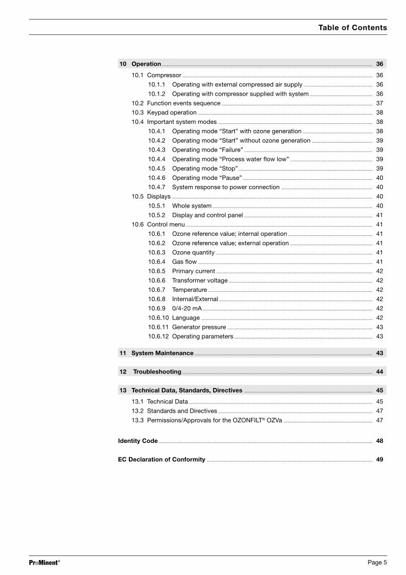
Fig. 3: System cabinet, right side Fig. 4: Adsorber drier, front view
13
2
13
14
26627
1
37
2
DISPLAY
PO
WE
R-U
NIT
Cooling water inlet
Cooling water outlet
View insidedoor
Compressed air inlet
Hose PE d=6/4
Hose socket ∅6,when delivery without Compressor: I 1/4"
Hose PE d=6/4

ProMinent® Page 13
Fig. 5: Compressor unit with solenoid valve fordrainage of condensate
25
Ozone gas output
Gas inputCooling water output
Cooling water inlet
Fig. 7: Ozone generator
Fig. 6: Pneumatic flow diagram
System components and what they do
1 air cleaning unit2 pressure release valve3 safety valve system input 7 bar4 solenoid valve system input5 drier unit6 regulating valve operating air for
ozone production7 gas flow controller8 ozone generator9 regulating valve cooling water
10 cooling water flow controller withmin. contact
11 double spring loaded back pressurevalve
12 solenoid valve ozone output18 mixing pipes19 blind24 spring loaded back pressure valve25 solenoid valve for removing
condensat from compressors vessel26 manometer operating pressure ozone
generator27 regulating valve regeneration air28 back pressure valve drier29 back pressure valve drier30 safety valve ozone generator 2.5-3 bar31 solenoid valve block driers32 solenoid valve cooling water input35 compressor unit w. vessel,
safety valve, pressure switch(6 bar < p < 8 bar) and condensatremoving solenoid valve
36 temperature cooling water outlet
PI
PI
T
31
30 6
26
7 2829
278
5
24
32
3
4
10
9
1
2
18
19
8
12
11 36
35
25
5

ProMinent®Page 14
1 Air cleaning unit - filter Residual oil and water from the compressed air are extracted by the filter.
2 Pressure release valve Used to set the system priming pressure of approx. 6 bar.
3 System inlet, bypass valve, 7 bar The bypass valve limits the system priming pressure to a maximum 7 bar.
4 System inlet, solenoid valve The solenoid valve serves to direct the compressed air to the adsorber drier.
5 Adsorber drier The adsorber drier reduces the dewpoint of the air intake to below -60 ºC.
6 Regulating valve, process air The process airflow is adjusted via the regulating valve.
7 Flow meter, gas The gas flow meter measures and monitors the process airflow.
8 Ozone generator In the water-cooled ozone generator, part of the oxygen contained in the air isconverted into ozone via a process of silent electrical discharge.
9 Corner valve, cooling water inlet The cooling water flow is adjusted at the corner valve.
10 Flow monitor for cooling water Detects when the cooling water flow is below the minimum threshold.
11 Spring loaded double non return valve, The spring loaded double non-return valve situated at the ozone generatorozone outlet outlet prevents any process water from escaping from the mixing tank into the
ozone generator.
12 Ozonated air-loading valve The solenoid valve transfers the ozonated air to the metering point and into themixing tank situated downstream.
13 Bleed valve for air cleaning unit Condensate which collects in the glass cylinder of the air-cleaning unit drainsout here.
14 Electronic controller The electronic controller is fitted with a microcomputer which controls andmonitors the entire system.
15 HV transformer power supply Controls the high voltage transformer.
16 Display and control unit For the display and adjustment of control parameters.
17 High voltage transformer This transformer produces the voltage; approx. 8000 V, required by the ozonegenerator.
18 Mixer Mixes the raw water with the ozonated air.
19 Mixing tank Where the raw water flow, now containing ozone, is extracted from the mixingtank outlet.
20 Raw water flow monitor Monitors the flow of raw water.
21 Safety screen Protects against contact with electrically charged parts.
22 Door trip switch If the safety screen is removed the door trip switch turns the system off.After replacing the safety screen the system can be switched on again.
23 Main/emergency off switch The system is switched on at the main switch. This switch also serves as anemergency cut-out switch.
24 Non-return valve, ozone inlet The spring loaded non-return valve at the entrance to the ozone generatorprevents ozonated air passing back out of the ozone generator and into the airdrier.
25 Solenoid valve, compressor The compressor solenoid valve opens periodically in order to releasecondensate from the pressure vessel.
26 Pressure gauge, This pressure gauge displays the pressure in the ozone generator (maximumozone operating pressure pressure 2 bar).
27 Regenerating air regulating valve The regulating valve on the adsorber drier is used to readjust the regeneratingairflow.
30 Ozone generator bypass valve The bypass valve limits the operating pressure of the ozone generator toapprox. 2.5 bar.
System components and what they do

ProMinent® Page 15
2.2 Functions of individual components
2.2.1 The air treatment system
The system requires air compressed to a minimum of 6 bar to be fed to the entrance to the aircleaning unit (2). The air-cleaning unit is designed for a maximum operating pressure of 10 bar.
The compressor (if supplied with the system) draws in surrounding air and compresses it toapprox. 6 - 8 bar. The compressor incorporates a pressure vessel and a bypass valve whichlimits the operating pressure in the pressure vessel to approx. 8 bar. The pressure vessel acts asa buffer and allows the air which has been heated during compression to cool.
The water, which is precipitated during compression, is drained off via a solenoid valve (25)connected to the pressure vessel on the compressor. The solenoid valve is opened at regularintervals by the system controller. Most of the condensate from the compressor is therebyextracted from the pressure vessel.
The remaining condensate from the compressed air is removed from the compressor via theself-bleeding filter (1).
2.2.2 Adsorber drier
The adsorber drier (Fig. 4), connected downstream from the compressor, is designed forambient temperature of a max. 40 ºC and air humidity of up to 85 %. The pressure dewpoint ofthe air at the outlet (6) of the adsorber drier is less than -60 ºC:
Preconditions • The system priming pressure and the regeneration air quantity are maintained at levelsgiven in 13 “Technical Data”.
• The maximum process airflow is not exceeded.
The process airflow is monitored by the electronic controller (14) to ensure the maximumthreshold is not exceeded. If this value is exceeded the system switches off.
A corresponding failure message appears in the display.
The system incorporates two adsorber driers which proceed alternately through drying andregenerating phases. The phase-switching is controlled by the electronic controller (14).
Compressed process air for the ozone generator passes firstly through an adsorber which isdedicated to air-drying. The desiccant contained in the adsorber draws the residual moisture outof the air.
At the same time, a partial flow of dried air which has been decompressed to atmosphericpressure is fed to a second adsorber facing in the opposite direction. This serves to regeneratethe desiccant, extracting and disposing of the water that it has adsorbed.
The phase switching time between drying and regeneration is set to ensure a stable pressuredewpoint (< - 60 ºC) of process air even in unfavourable conditions.
The flow of process air is adjusted by the regulating valve (6) on the adsorber drier, and the flowof regenerating air is adjusted by regulating valve (27) (see Fig. 4).
The air quantities required for the correct use of the system are given in section 13 “TechnicalData”.
WARNING
The system cabinet must be opened and the safety screen removed to adjustthe airflows.
Please follow the safety guidelines in sections 5 and 9.
2.2.3 The ozone generator
The ozone generator contains two identical ozone generating elements. One element consists ofa metal tube, a high-voltage electrode, an insulator and an earthed electrode. The dried air flowsbetween the outer metal tube and the outer surface of the high-voltage electrode through theozone generator. It then passes in the opposite direction between the inner surface of the high-voltage electrode and the insulator. By feeding the gas in this way, if the actual generatorelement seals become defective, it is impossible for ozone to leak out of the system. Analternating high voltage in the medium frequency range is passed between the inner high-voltage electrode and the earthed electrode. Cooling water is passed between the earthedelectrode and the inner surface of the insulator. By means of silent electric discharge, a part ofthe oxygen contained in the air is converted into ozone. The voltage required depends upon theoperating pressure; shown on the pressure gauge (26).
System components and what they do
ProMinent®Page 16
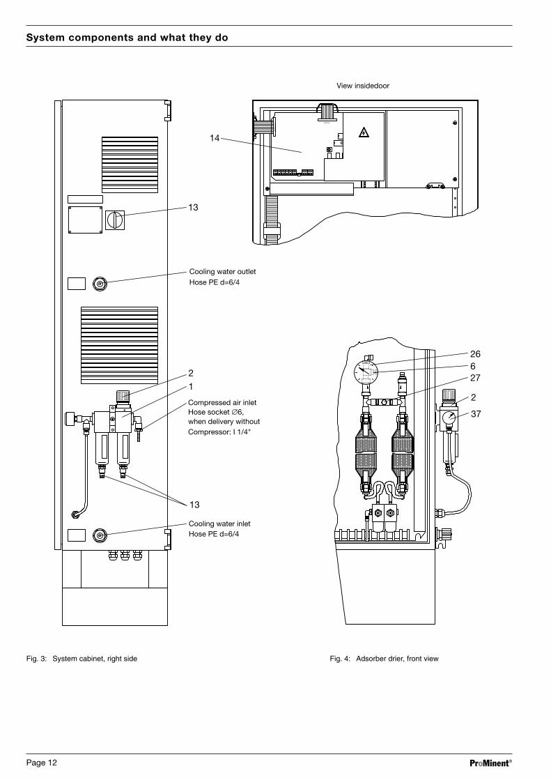
2.2.4 The ozone generator electronic controller
The system is fully controlled and monitored by the electronic controller (14).
The controller performs the following tasks:
• Controls the HV transformer power supply (15) for the generation of an alternating highvoltage in the medium frequency range,
• Measures and monitors the system supply voltage,
• Measures and monitors the primary voltage of the high voltage transformer (17),
• Measures and monitors the primary current of the high voltage transformer (17),
• Measures and monitors the frequency for the high voltage generator,
• Measures and monitors the gas flow through the ozone generator,
• Measures and monitors the operating hours of the system,
• Monitors the cooling water flow,
• Monitors the process water flow,
• Time-controls the solenoid valves on the adsorber drier,
• Time-controls the water bleed valve on the compressor pressure vessel,
• Control of solenoid valves on the cooling water inlet, at the gas inlet and at the ozone outlet,
• Actuates a fault indicating relay to signal system failures,
• Allows the use of an isolated pause input,
• Allows the use of an isolated standard signal input (0/4-20 mA) for automatic control of theozone quantity,
• Allows the use of a switch input for an ozone gas detector,
• Displays all relevant system parameters in the display and control panel (16),
• Processes all key commands entered at the display and control panel (16).
2.2.5 The electronic control of the power supplyfor the ozone generator
The electronic power supply controller (15) supplies an alternating voltage in the mediumfrequency range to the high voltage transformer (17). The high voltage transformer (17) therebyproduces the alternating high voltage required for ozone generation. Supplying a mediumfrequency range voltage offers significant advantages for ozone generation as compared withthe mains frequency supply that is normally used, improving the efficiency of the ozonegeneration and at the same time reducing the size of the actual ozone generator unit. Theelectronic controller also allows complete control of all system parameters for the ozoneproduction process.
2.2.6 Mixing system
The ozone is fed to the process water flow via a non-return valve (11) and a solenoid valve (12).The spring loaded double non-return valve (11) prevents water from entering the ozonegenerator. The solenoid valve (12) is always closed when the system is in pause, stop or failuremode.
Mixing and dissolving is carried out immediately after metering by the mixers (18).
System components and what they do

ProMinent® Page 17
2.3 Safety equipment
2.3.1 Flow monitor
In accordance with German safety directives ZH 1/474 and GUV 18.13 (Directives for the Use ofOzone in Water Treatment), ozone may only access the mixing system when the process waterflow is above the minimum flow threshold.
In addition, it is necessary to halt ozone dosage by stopping the circulation pump. This can beperformed by the pause input on the electronic controller (14).
The system starts independently at the preset “Ozone reference value” when
• The pause signal is inactive (switch input XPs is closed),
• There is no other failure present.
2.3.2 Trip switch
In order to prevent contact with electrically charged parts, the OZONFILT® OZVa is fitted with adoor trip switch (22).
WARNING
Do not short-circuit the door trip switch (22). This can result in life-threateninghigh-voltages passing through parts of the system. Even when the door tripswitch is released, or the main switch is OFF, parts of the system may still besubject to mains voltage. For this reason the system must be disconnectedfrom the mains power supply before any work is carried out on it.
2.3.3 Emergency cut-out in ozone system control room
The safety directives ZH 1/474 and GUV 18.13 stipulate that it must be possible to switch offozone systems with an emergency cut-out switch (emergency command system). Thisemergency cut-out switch must be located in an easily accessed and safe position near thedoor of the ozone system control room. The emergency cut-out switch must cut off theelectrical power supply to the system.
2.3.4 Main / Emergency off switch on system
The system is switched on via a mains power supply switch (23). This switch also serves as theemergency cut-out switch.
2.3.5 Bypass valves
The bypass valve (3) at the entrance to the system limits the priming pressure of the system toapprox. 7 bar. The bypass valve downstream from the regulator, used to adjust the processairflow (6), limits the pressure in the ozone generators to approx. 2.5 bar. It thereby protects theelectronic components from overload.
2.3.6 Non-return valves
The spring loaded non-return valve (24) at the entrance to the ozone generator preventsozonated air from re-entering the air treatment system from the ozone generator.
The spring loaded double non-return valve at the outlet of the ozone system (11), upstream fromthe solenoid valve (12) and situated on the outlet side, prevents process water from escapingfrom the mixer into the ozone generators.
System components and what they do

ProMinent®Page 18
2.3.7 Gas detector
In accordance with the current German commercial trade associations’ safety directives(ZH 1/474 and GUV 18.13), rooms in which ozone gas leaks might occur as a result of systemfailure must be monitored by a gas detector.
These directives apply to ozone systems with ozone generating capacity of 2 g/h or more,irrespective of whether the gas containing ozone is above (positive pressure systems) or below(negative pressure systems) atmospheric pressure.
The gas detector should be located at the point at which the highest concentration of ozone gascould be expected in the event of a system failure. In positive pressure systems the gasdetector should be installed in the vicinity of the ozone generating system, in negative pressuresystems, in the vicinity of the exhaust ozone gas destructor. The OZVa is a positive pressuresystem.
The alarm threshold of the gas detector can be set to an ozone concentration of 1.0 mg/m3.
The gas detector must be fitted with optical and audio warning indicators.
In the case of the OZONFILT® OZVa the gas detector is fitted with an isolated alarm switch. Thismust be connected to the XOz input on the electronic controller (14) as instructed in theaccompanying system circuit diagrams (see also Fig. 8.2 “Electronic In/Outputs”).
Outside Germany, please observe applicable national regulations and directives.
System components and what they do
ProMinent® Page 19
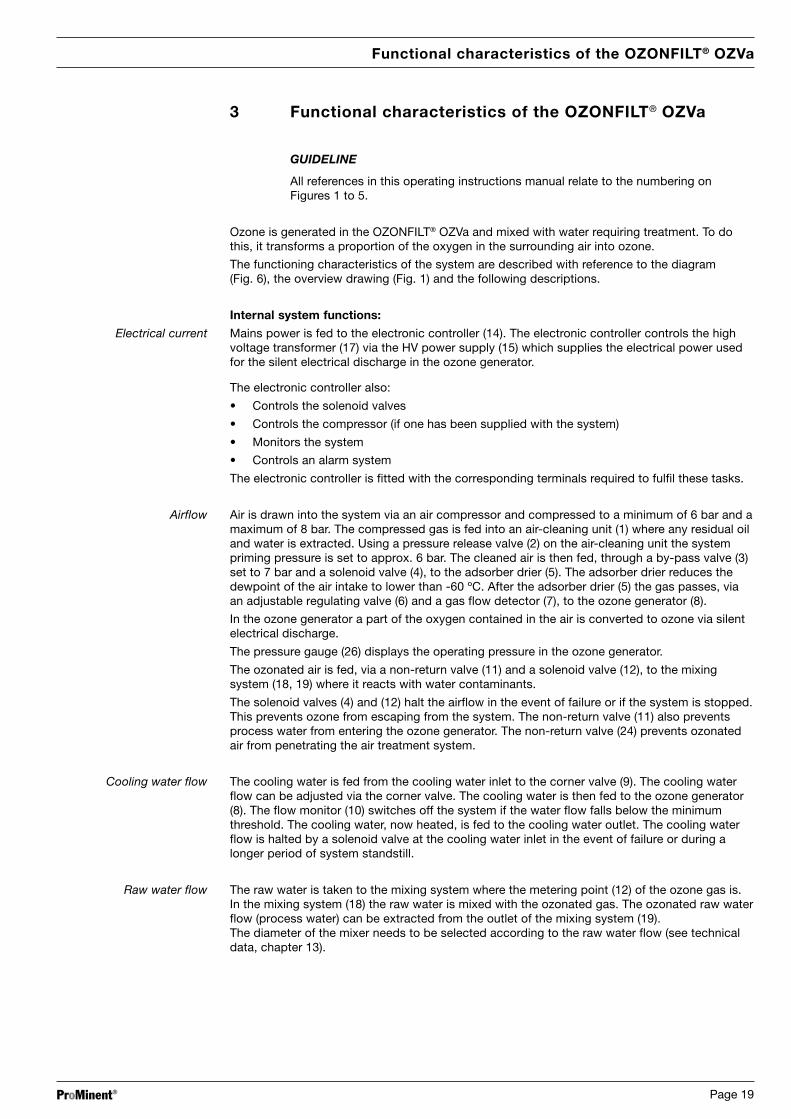
3 Functional characteristics of the OZONFILT® OZVa
GUIDELINE
All references in this operating instructions manual relate to the numbering onFigures 1 to 5.
Ozone is generated in the OZONFILT® OZVa and mixed with water requiring treatment. To dothis, it transforms a proportion of the oxygen in the surrounding air into ozone.
The functioning characteristics of the system are described with reference to the diagram(Fig. 6), the overview drawing (Fig. 1) and the following descriptions.
Internal system functions:
Electrical current Mains power is fed to the electronic controller (14). The electronic controller controls the highvoltage transformer (17) via the HV power supply (15) which supplies the electrical power usedfor the silent electrical discharge in the ozone generator.
The electronic controller also:
• Controls the solenoid valves
• Controls the compressor (if one has been supplied with the system)
• Monitors the system
• Controls an alarm system
The electronic controller is fitted with the corresponding terminals required to fulfil these tasks.
Airflow Air is drawn into the system via an air compressor and compressed to a minimum of 6 bar and amaximum of 8 bar. The compressed gas is fed into an air-cleaning unit (1) where any residual oiland water is extracted. Using a pressure release valve (2) on the air-cleaning unit the systempriming pressure is set to approx. 6 bar. The cleaned air is then fed, through a by-pass valve (3)set to 7 bar and a solenoid valve (4), to the adsorber drier (5). The adsorber drier reduces thedewpoint of the air intake to lower than -60 ºC. After the adsorber drier (5) the gas passes, viaan adjustable regulating valve (6) and a gas flow detector (7), to the ozone generator (8).
In the ozone generator a part of the oxygen contained in the air is converted to ozone via silentelectrical discharge.
The pressure gauge (26) displays the operating pressure in the ozone generator.
The ozonated air is fed, via a non-return valve (11) and a solenoid valve (12), to the mixingsystem (18, 19) where it reacts with water contaminants.
The solenoid valves (4) and (12) halt the airflow in the event of failure or if the system is stopped.This prevents ozone from escaping from the system. The non-return valve (11) also preventsprocess water from entering the ozone generator. The non-return valve (24) prevents ozonatedair from penetrating the air treatment system.
Cooling water flow The cooling water is fed from the cooling water inlet to the corner valve (9). The cooling waterflow can be adjusted via the corner valve. The cooling water is then fed to the ozone generator(8). The flow monitor (10) switches off the system if the water flow falls below the minimumthreshold. The cooling water, now heated, is fed to the cooling water outlet. The cooling waterflow is halted by a solenoid valve at the cooling water inlet in the event of failure or during alonger period of system standstill.
Raw water flow The raw water is taken to the mixing system where the metering point (12) of the ozone gas is.In the mixing system (18) the raw water is mixed with the ozonated gas. The ozonated raw waterflow (process water) can be extracted from the outlet of the mixing system (19).The diameter of the mixer needs to be selected according to the raw water flow (see technicaldata, chapter 13).
Functional characteristics of the OZONFILT® OZVa

ProMinent®Page 20
Functional Characteristics of the OZONFILT® OZVa
Raw water Filtration
Ambient ozonemonitor
Cooling water
Ozone generator
Mixing and dissolving system
Compressor Air preparationDryers
High voltagegeneration
Microprocessor controller
Micro-electronic process monitor
• Ozone quantity• Airflow• Current• Voltage• Operation hour
counter
D I S P L AY
Gas flow meter
Flow meter
Cooling water monitor
Temperaturecontrol
Temperaturemeasurement
Ozonated raw water
Treated, ozone-free water
Exhaust ozone destructor
Flow diagram of water treatment using the OZONFILT® OZVa, Type 4
Fig. 7: Flow diagram of system

ProMinent® Page 21
Application, design and integration of the system
4 Application, design and integration of the system
4.1 Correct use
The OZONFILT® OZVa is an ozone generating and metering stage which has been developed forgeneral water treatment for the purpose of oxidising water contaminants. Correct usage of thisequipment requires the proper installation of the system in a water treatment system.
It is particularly important to follow the procedures outlined in section 7 “Assembly and In-stallation”. When installing in swimming pool systems it should be noted that the treatedwater must be entirely free from ozone prior to entering the pool itself.
4.2 System design
The OZONFILT® OZVa system has been designed for water treatment and is used to generateand meter ozone to a flow of raw water. The user can adjust the ozone concentration to anyvalue between 0 and 100 % (see section 10, “Operation”, 10.6.1).
An on-site booster pump, if necessary with a pressure release/bypass valve, is required tosupply the correct flow volume. DIN 19643, section 5 (Design) requires that the system shouldbe fitted with a reaction tank downstream, to ensure a sufficient reaction period, and a filter witha layer of activated carbon. This should incorporate a means of venting exhaust ozone gas outof the building via an exhaust ozone gas destructor.
WARNING
Observe all general directives and safety regulations when installing andoperating the system.
In Germany in particular the currently valid version of DIN 19627 and the directives forprevention of accidents to industrial employees (ZH 1/474 and GUV 18.13: Guidelines for theUse of Ozone in Water Treatment) must be observed. We recommend that these guidelines beread and the OZONFILT® OZVa ozone system be installed and assembled correspondingly.
GUIDELINE
The operator has the duty to create a working directive (including instructions foravoiding danger, and an alarm plan) taking into account the local conditions on side.
As further sources of information apart from the operating instructions manual, thefollowing German directives of the main league of the trade associations and of thetrade association of the chemical industry can be taken into consideration too:a) ZH 1/474 “Directives for the use of Ozone in water processing”b) ZH 1/262 “Spezification leaflet 052 Ozone”
4.3 Incorporating OZONFILT® OZVainto water treatment systems: swimming pool water treatment
4.3.1 Design of OZONFILT® OZVa
Swimming pools fitted with an ozonising stage are designed for a flow volume of 1.67 m3/h perbather. The ozone dosage, depending upon pool temperature, is between 0.8 and 1.5 g/h ozoneper m3/h circulating flow volume. In water temperatures of above 30 ºC, an ozone dosage ofbetween 1.2 and 1.5 g/h per m3/h circulating flow volume is recommended.
The OZONFILT® OZVa system is designed to treat a flow volume of between 10 - 35 m3/h(depending upon mixer version, refer to chapter 13, Technical Data).
For larger flow volumes, the OZVa is connected in bypass.
If the raw water flow through the mixing system is lower than specified in chapter 13 (TechnicalData) the mixing and dissolving performance maybe insufficient.

ProMinent®Page 22
Application, design and integration of the system
4.4 Ozone generating system for water treatment in swimming pools
Certain requirements must be met in order to use ozone technology in swimming pools:
Ozone must be added to the water in sufficient quantities. In order to ensure optimum dissolvingof the ozone in the water, the ozone concentration in the gas phase must be high. DIN 19627stipulates an ozone concentration of 20 g/m3 under normal environmental conditions for thetreatment of water in swimming pools.
GUIDELINE
After the ozone metering point there must be fitted a reaction tank in which theozone reaction can take place. The reaction tank should be large enough to ensurethat the water takes 3 minutes to flow though the tank at maximum circulationvolume (DIN 19643).
TAKE CARE
When treating swimming pool water, the filtration stage connected downstreammust incorporate a layer of activated carbon in which the oxidised substancesare retained. The exhaust ozone must be completely removed from the liquidbefore the water can re-enter the swimming pool.
The exhaust gas containing ozone must be vented out of the system via a gasexhaust valve. This gas exhaust valve must be located downstream from anexhaust destructor.
4.5 Installation
Fig. 8 illustrates the typical installation of the OZONFILT® OZVa into a pool water treatment.
See chapter 7.3 for details.
Typical Pool Installation of the OZONFILT® OZVa, Type 4
Multilayer Filterwith Activated carbon
layer, min. 600 mm
Reaction-tank
Exhaust air treatment pH correction
Disinfection
Fig. 8: Installation of OZONFILT® OZVa, Type 4 in a swimming pool

ProMinent® Page 23
Safety Guidelines
5 Safety Guidelines
OZONFILT® OZVa systems employ the latest technology in order to guarantee the highest levelof operating and functional safety. In this section you will find all the information required for thesafe operation of the system. Please read and observe the safety guidelines. Keep theseinstructions in an accessible place in the vicinity of the system.
5.1 Correct use
The OZONFILT® OZVa is an ozone generating and metering system which has been developedfor general water treatment for the purpose of oxidising water contaminants. Correct usage ofthis equipment requires the proper installation of the system into a water treatment system.
5.2 Servicing and repair
WARNING
All maintenance and repair work must be carried out by qualified personnel whohave been authorised by ProMinent.
Qualified personnel are persons who, as a result of specialised training andexperience, have sufficient knowledge in the field of ozone systems, and aresufficiently familiar with relevant national legislature on safety at work, accidentprevention, directives and general technical regulations to be able to correctlyjudge the safety conditions within an ozone system.
When installing in swimming pool systems it must be ensured that the treated water iscompletely ozone-free before being fed into the pool.
Interference from unauthorised personnel renders void all guarantees or liability claims on behalfof the operator.
5.3 Displaying safety signs
The warning/prohibition notice accompanying the system must be displayed at the entrance tothe control room of the OZONFILT® OZVa in accordance with the German guidelines for ozonesystems DIN 19627.
This sign bears the inscription:
“Ozone system - access only to trained personnel”, the hazard symbol and the no smokingsymbol.
The sign must be permanently fixed in position and clearly recognisable.
5.4 General guide to safety equipment
WARNING
• Never decommission safety equipment!
• Never bypass or short-circuit a safety device!
5.5 Electrical safety equipment
5.5.1 Emergency cut-out in ozone system control room
The safety directives ZH 1/474 and GUV 18.13 stipulate that it must be possible to switch offozone systems by an emergency cut-out switch (emergency command system). This emergencycut-out switch must be located in an easily accessed and safe position near the door of theozone system control room. The emergency cut-out switch must cut off the power supply to thesystem.

ProMinent®Page 24
Safety Guidelines
5.5.2 Main / Emergency cut-out (23) switch on system (Fig. 3)
The system is switched on via a mains power switch (23). This switch also serves as theemergency cut-out switch.
5.5.3 Trip switch (22)
WARNING
Do not short-circuit the door trip switch (22). This can result in life-threateninghigh-voltages passing through parts of the system. Even when the door tripswitch is locked, or the main switch is OFF, parts of the system may still besubject to mains voltage. The system must be disconnected from the mainspower supply before any work is carried out on it.
5.6 Operating safety equipment
5.6.1 Flow monitor
In accordance with safety directives ZH 1/474 and GUV 18.13 (Directives for the Use of Ozonein Water Treatment), ozone may only access the mixing system when the process water flow isabove the minimum flow threshold.
For this reason it is necessary to stop the ozone generation if the raw water flow is below alower limit (suggestion: 50 % of the nominal flow through the mixer).
There are two possibilities to perform the interlocking:
• if the installation allows it, the system can be interlocked with a potential free contact at thecirculation pump connected to the pause input of the plant (refer to chapter 8.2). When thecirculation of the main water stream is stopped, then the ozone plant is automaticallyswitched into pause state.
• if the interlock of the system with the circulation pump is not possible, it is necessary toinstall a flow monitor with minimum contact at the raw water input of the mixing unit. Theminimum contact must be connected to the input XPD of the controller board (refer tochapter 8.2).
The flow monitor device with min.-contact is not included in standard delivery content.
The system starts automatically at preset “Ozone reference valve” when
• the pause signal is inactive (switch input XPs is closed),
• the flow monitor (if connected to input XPD) registers a, sufficiently high raw water flow,
• there is no other failure present and
• the system is not deactivated via “STOP/START” key.
Refer to chapter 8.2 and the terminal diagrams for details of the electrical installation.
5.6.2 Gas detector
In accordance with the current German commercial trade associations’ safety directives(ZH 1/474 and GUV 18.13), rooms in which ozone gas leaks might occur as a result of systemfailure must be monitored by a gas detector. These directives apply to ozone systems withozone generating capacity of 2 g/h or more, irrespective of whether the gas containing ozoneis above (positive pressure systems) or below (negative pressure systems) of the atmosphericpressure.
The gas detector should be located at the point at which the highest concentration of ozone gascould be expected in the event of a system failure. In positive pressure systems the gasdetector should be installed in the vicinity of the ozone generating system, in negative pressuresystems, in the vicinity of the exhaust ozone gas destructor.
The alarm threshold of the gas detector can be set to an ozone concentration of 1.0 mg/m3.
The gas detector must be fitted with optical and audio warning indicators.
Outside Germany, please observe applicable national regulations and directives.

ProMinent® Page 25
Delivery Range, Storage and Transport of the system
6 Delivery Range, Storage and Transport of the system
6.1 Options
The system comprises several component groups:
Minimum installation:
Control cabinet with
a) Air cleaning unit (on the outside of the control cabinet),
b) Adsorber drier and airflow monitoring unit,
c) Ozone generator,
d) Electronic controller with display and control panel,
e) Electronic HV transformer power supply for the ozone generator,
f) Mixing system.
Enhanced installation (on request only):
g) Compressor (the compressor is located outside the control cabinet),
h) Ozone gas detector.
The compressor is included in the equipment if indicated in the order. The ozone gas detector,required in order to comply with conditions for the correct use of the system, is available as anoptional accessory.
TAKE CARE
Those component groups required in order to comply with the conditions forcorrect use of the system, e.g. the adsorption filter, reaction tank and exhaustozone exhaust gas destructor, are not included in the delivery range of thissystem.
6.2 Storage
TAKE CARE
The system must be stored at a temperature of between 5 °C and 40 °C.
6.3 Transport
WARNING
• The system must be transported with care. Take extra precautions toprotect the system from jolting en route.
• When unpacking, ensure the system is placed on a stable base.

ProMinent®Page 26
Assembly and Installation
7 Assembly and Installation
7.1 Safety Guidelines
WARNING
The system produces ozone gas using high voltages. For safety reasons, thissystem must be maintained and commissioned by qualified personnel.Unauthorised handling of the system or any part of the system may result inlife-threatening high voltage electrical shocks or the leakage of toxic gas.
Qualified personnel must receive training in this system from the manufacturer.
7.2 System location requirements
The system produces ozone gas using high voltages. For safety reasons, this system must bemaintained and commissioned by qualified personnel. Unauthorised handling of the system orany part of the system may result in life-threatening high voltage electrical shocks or theleakage of toxic gas.
Qualified personnel must receive training in this system from the manufacturer.
The directives for the use of ozone for water treatment (ZH 1/474 and GUV 18.13) stipulate thatozone systems are to be located in closed secure rooms to which access is permitted only toauthorised personnel.
In addition, rooms where ozone systems are located must not contain any permanentworkplaces. If this requirement is not met, technical measures must be taken to ensure that theozone concentration in the room cannot exceed the MAK value of 0.2 mg/m3 (as for toilets withno direct exit to the outdoors).
The control room must be monitored by a gas detector which will switch off the system in theevent of a gas leak.
The surrounding air must be free from dust and aggressive fumes.
The surrounding temperature must not exceed 35 ºC and the relative humidity must not exceed85 % (non-condensing).
7.2.1 Displaying safety signs
The warning/prohibition notice accompanying the system must be displayed at the entrance tothe control room of the OZONFILT® OZVa in accordance with DIN 19627.
This sign bears the inscription:
“Ozone system - access only to trained personnel”, the hazard symbol and the no smokingsymbol.
The sign must be permanently fixed in position and clearly recognisable.
7.3 Requirements of the system components
TAKE CARE
Ozone-resistant material must be used for all system components which cancome into contact with ozone in either gas form or in an aqueous solution. Thisapplies especially to the pipe work system, the reaction tank, the activatedcarbon filter including all exhaust gas components and wherever there may bepossible contact with ozone.

ProMinent® Page 27
Assembly and Installation
7.3.1 Mixing modules
The mixing modules need to be selected according to the water flow:
Flow volume of the process water through the OZONFILT® OZVa:
Flow volume Diameter Identity code (see device label)
15 - 25 m³/h DN 65 OZVa x x 5 x X
25 - 35 m³/h DN 80 OZVa x x 6 x X
35 - 50 m³/h DN 100 OZVa x x 7 x X
Pressure range at the ozone outlet 0.8 - 1.5 bar.
For the connection of the ozone gas outlet to the dosage point at the mixing module a stainlesssteel pipe connection is necessary.
In the standard delivery of the OZVa two steel pipes (1.40 m length, diameter 12/10,material 1.4571, order number 15743) and one angle union (90° D12-D12, order number1006397) are enclosed.
Longer steel pipes and more angle unions are available on request.
CAUTION
The pipe length and the number of connections has to be minimized, for safetyreasons.
According to the German safety guidelines a gas warning device is necessary in each room witha connection point of the ozone gas pipe.
CAUTION
The pipework has to be tested for leakages.
In order to do that the OZONFILT® OZVa is set to 0 % ozone production and switched on withnominal gas flow at the expected operation back pressure.
7.3.2 Reaction tank (optional accessory)
In order to exploit the capacity of the ozone thoroughly, the reaction time at pool installationsmust be at least 3 minutes. This can be achieved by installing a reaction tank or increasing thefreeboard of the filter located downstream. This is where the water contaminants are oxidisedand disinfection takes place. The exhaust gas remaining in the water must be vented out of thesystem by means of an “exhaust ozone gas extraction system”.
7.3.3 Filtration (optional accessory)
In a swimming pool system the ozonising stage must be followed by a filter. The filter removesdestabilised colloids, clumped and coated micro organisms, ozone-flocculated organic reactionproducts and dissolved, residual ozone from the water. For this purpose, open rapid filterscomplying with DIN 19695 as multi-layer filters, activated carbon filters or mixed bed filters areused.
The filtration system must be fitted with a powerful gas exhaust system for the extraction of gascontaining exhaust ozone. The gas extraction system must be ozone-resistant and should bechecked at regular intervals to ensure it is functioning correctly.
CAUTION
If the function of the gas extraction system in the filters or reaction tank is notguaranteed there exists the danger that ozonated water will pass through thesystem into, e.g. the swimming pool. This must be prevented from happening atall costs by adequate maintenance of the reaction tank and the filter system.

ProMinent®Page 28
Assembly and Installation
The filtration system should be installed so that it cannot run dry. The clean water pipe shouldbe fitted above the upper liquid level so that the highest point is situated above the filter. A pipebleed valve should be installed at this point.
In order to avoid airlocks the clean water outlet (leading to the pool) should be regulated afterventilation. The regulating mechanism should be situated beneath the surface of the water.
A non-return valve is fitted inside into the raw water inlet (coming from the pool) to preventwater flowing back into the pool.
7.3.4 Exhaust ozone gas extraction system (optional accessory)
ProMinent uses activated carbon cartridges for the removal of exhaust ozone. The water shouldbe extracted from the exhaust gas mixture which emerges from the reaction tank and the filterusing a suitable pipe outlet. The purified air is eventually vented out of the building.
7.4 Mechanical Assembly
7.4.1 System cabinet
WARNING
After unpacking, care should be taken that the system is placed on a stablebase.
The OZVa 4 is supplied in a floor standing control cabinet.
The system should be put in a place which allows easy access for maintenance work.
Additional fixing at the backwall is necessary. If this is not possible the cabinet has to besecured against falling over.
At the left and rigtht side a space of 30 cm at least is necessary for proper operation of coolingfans, and for easy access to the air cleaning unit for maintenance purposes.
Assembly materials The following assembly components are supplied with the system:
• 4 stern screws M8x80
• 8 rubber spacers (for assembly with mounting plates only)
• 4 washers, 24 mm Ø
• 4 nuts M8
Assembly steps
Assembly � Drill 4 x 10 mm Ø holes for the plugs (as shown in the drilling plan).
� Screw M8 bolts into plugs.� Put the cabinet in place.� Place washers over bolts.� Fix the system in position using the nuts provided.

ProMinent® Page 29
Fig. 11: Measurements and installation plan
Assembly and Installation65
6
230
718
1142 229
240910
800
14001200
630
600
310
300
250
180
180
DU
LCO
ME
TE
R
STA
RT
STO
P3O
Ozo
ne o
utp
ut: R
1/4"
insi
de
thre
ad
Kit
f. oz
one
gas
mon
itor
Coo
ling
wat
er in
let
for
∅6/
4 tu
be
Coo
ling
wat
er o
utle
t fo
r ∅
6/4
tub
e
Wal
l fas
teni
ng s
yste
mS
tern
-scr
ew M
8x80
R
R
Iden
tity
cod
e O
ZV
a 3x
4xx
Flan
ge D
N 5
0 /
d=
63
Iden
tity
cod
e O
ZV
a 3x
5xx
Flan
ge D
N 6
5 /
d=
75
Iden
tity
cod
e O
ZV
a 3x
6xx
Flan
ge D
N 8
0 /
d=
90

ProMinent®Page 30
Assembly and Installation
7.4.2 Raw water pipes
All pipes
• To the system (raw water inlet: see Fig. 1) and• From the system (ozonated water outlet: see Fig. 1)
should be made of rigid PVC, range 5. Ensure that they are laid free from stress. Keep allconnecting pipes as short as possible (max. 5 m).
The raw water pipe leading to the system must be fitted with a non return valve in an ozone-resistant material.
The outlet pipe should be arranged in such a way that it is rising continuously. If the connectionpoint on the reaction tank/filter is lower than the line itself, the height difference must becompensated by a pipe inserted vertically. The height difference at the outlet of the OZONFILT®
OZVa must not exceed 1 m.
7.4.3 Compressed air system
� If the system is supplied with a compressor this is connected using the delivery hosesupplied (Ø 12 mm) from the hose nozzle of the compressor to the air cleaning unit inlet (2)on the left hand side of the system. The hose ends are clamped tightly to each nozzle(compressor and system inlet) using the hose clamps supplied.
� The hose and the connections have to be tested for leakages after installation.
The PE tube supplied with the compressor (4 mm) is attached to the hose nozzle on the soleno-id valve (25) on the compressor. This is used to bleed the condensate from the pressure vessel.The hose should be fed to a suitable container in which to collect the condensate expelled fromthe pressure vessel.
During automatic condense bleeding, small amounts of water can drain out of the hose on thebleed valve (25) on the compressor and the bleed valves (13) on the air-cleaning unit (2). Thequantity of condensate referred to depends upon the air humidity in the location where thesystem is in use. It is recommended that the condensate be collected in a container with acapacity of more than 5 litres (not supplied with system). The container should be emptiedregularly in order to prevent it from overflowing.
� This also applies to the bleed valves (13) on both filter containers on the air-cleaning unit (2).For condensate drainage, use the polythene (Ø 6x4) delivery hoses (supplied). Deliveryhoses should be attached to the hose nozzles located on the underside of both filters. Bothdelivery hoses must be fed to the collection container.
� All condensate hoses should be fixed in a suitable way in order to prevent unduemovement during bleeding.
TAKE CARE
Take care that the regenerating air hose projecting from the bottom of thesystem (PE delivery hose, one open end) does not become blocked. Theregenerating air hose must be allowed to bleed unobstructed.
� If the system was not supplied with a compressor, a suitable pneumatic connection shouldbe created from the air compression system to the inlet of the air cleaning unit (2) on theright hand side of the system.
CAUTION
The connection from the air compression system to the main system must besufficiently pressure resistant for the air compression system. The maximumpositive operating pressure, however, must not exceed 10 bar (see section 13“Technical Data”).

ProMinent® Page 31
Assembly and Installation
7.4.4 Cooling water system
� The cooling water system connections are made using PE delivery hoses (diameter 6x4)which are attached to the system cabinet using the PVC connector set provided (see Fig. 2).
� Ensure, when attaching hoses, that the O-rings are located in the groove of the PVCthreaded connector.
� The connection of the delivery hose to the cooling water inlet with the cooling water supplycan be created with the screw-in threaded connector (6/4-3/8"a), nickel-coated brass).
Specifications for the cooling water quality for the ozone generator:
TAKE CARE
If water priming pressure fluctuates widely or the water supply system hasbecome fouled, a filtration pressure relief valve should be installed upstreamfrom the cooling water inlet.
Flow volume (cooling water): 70 - 100 l/h
Cooling water inlet pressure: Max. 5 bar, no pressure surges
Cooling water outlet: Zero pressure
Cooling water quality: Drinking water, not desalinated water
Water temperature: < 30 ºC in ambient temperatures below 35 ºC< 25 ºC in ambient temperatures from 35-40 ºC

ProMinent®Page 32
8 Electrical installation
8.1 Guidelines to electrical connections
All electrical power leads to the system are passed into the system through the strain-relievingthreaded connectors on the underside of the system (see Fig. 2). The power leads are laid in theducts provided. After installation the threaded connectors are tightened. Any unused connectorsare sealed using the blind plugs provided.
TAKE CARE
The system is fully wired and ready for use. It simply needs connecting to a sin-gle-phase mains power supply. Ensure that phase, zero and earth leads areconnected in accordance with the system circuit diagram.
The system must be permanently connected to the power supply. It may not beplugged into a mains power supply via a domestic power cable!
Faulty connection to the power supply prevents correct functioning of safetyequipment, in particular the trip switch, which deactivates the system when thedoor is opened.
It must be possible to isolate the electrical socket with an emergency switch(emergency cut-out system). This should be installed in an easily accessedposition near to the entrance door to the system room.
� It must be possible to deactivate the ozone system by stopping the water treatment systembooster pump via the pause input XPs on the controller circuit board (see 8.2) “Electrical Inand Outputs”).
� If the system is supplied with a compressor, the time controller must be electricallyconnected to the solenoid valve (25) to control the condensate bleed function on thepressure vessel on the compressor. The connection lead (approx. 1.5 m long) with lead endis fed out through the strain-relieving threaded connectors on the underside of the system.It then simply requires screwing onto the solenoid valve on the compressor’s pressurevessel. Take care that the rubber washer provided is placed under the lead end.
� The compulsory gas detector must be fitted with an electrically isolated contact which isconnected to the clamps X3:11 and X3:12 (see circuit diagram).
� All other electrical connections must be made in accordance with the accompanying systemcircuit diagram.
8.2 Electrical inputs and outputs
The system is provided with the following inputs and outputs for the control of the ozonegenerator (see Fig. 13 “Electrical connections on the controller circuit board“):
• An ozone gas detector can be connected to the clamps X3:11 and X3:12 (see circuit dia-gram). The gas detector used must be provided with an isolated alarm switch which isconnected to the clamps.
• Standard signal input (X3:7 and X3:8 (0/4-20 mA)) for the control of the ozone quantitywithin a range of 0 % to 100 %. A current of 0 and/or 4 mA (depending upon the pre-settings in menu option “0/4-20 mA”) corresponds to an ozone quantity of 0 %. A current of20 mA corresponds to an ozone quantity of 100 %.The XmA input is only active if the ozone quantity setting in the menu option “Internal/external” has been activated (display: “1”). The XmA input is electrically isolated from allother electrical system components.
• Switch input XPs (X3:4 and X3:5) is a contact via which the system can be switched to PAU-SE mode. The switch input XPs is electrically isolated from all other electrical systemcomponents.
• Alarm output XUsr (X3:1,2,3) is used to transmit failure signals. The output is a change overcontact.It can be connected by the user to mains voltage (230 Veff / max. 8 A).
All electrical outputs are wired in such a way as to switch off the ozone generator should a faultin any of the leads develop.
Electrical Installation

ProMinent® Page 33
TAKE CARE
The XOz, XPs and XPD inputs on the terminal X3 are switch inputs. They cannotbe configured with external voltage! The contacts connected to the inputs mustbe potential free, otherwise the controller will be damaged!
Connection Function switch Status description Voltage and current Configurationcontact terminal X3
XOz Switch input for ozone Open: ozone alarm Open: +12 V 11: inputgas warning device Closed: normal Closed: 1.2 mA 12: ground
XmA Electrically isolated 0/4 mA: 0 % Resistance:current input 20 mA: 100 % approx. +1.7 V at 20 mA 6: +21 V/20 mA0/4-20 mA for the control 7: inputof the quantity of ozone 8: ground
XPs Electrically isolated Open: pause Open: +15 V 4: groundswitch input for Closed: normal Closed: 10 mA 5: inputpause function
XPD Switch input for Open: raw water low Open: +12 V 13: inputflow controller with Closed: raw water flow on Closed: 1.2 mA 14: groundminimum contact
XUsr Alarm relay Pin 3 � Pin 1: alarm Voltage free, 1: N/C contactPin 3 � Pin 2: normal can be connected 2: N/O contact
by the user 3: commonto 230 V/max. 8 A
Electrical Installation

ProMinent®Page 34
9 Commissioning
WARNING
Commissioning must be carried out by qualified personnel in accordance withZH 1/474 and GUV 18.13.
Outside Germany, the national regulations for the operation of ozone systemsmust be observed.
Qualified personnel for this system are persons who have received training andauthorisation from ProMinent.
Interference from unauthorised personnel renders void all guarantees or liabilityclaims on behalf of the operator.
The system produces toxic gas using high voltages of up to 8000 V.Unauthorised access to the system or any part of the system may result in livesbeing endangered.
Once the system has been installed, a function inspection must be carried out in order to detectany possible damage in transit. It must firstly be ensured that:
• All electrical, pneumatic and hydraulic connections are in order.
• The mains cutout is activated.
• The door is closed so that the trip switch in the door is released.
• The system’s main switch is on.
• All other system parameters are within permissible limits (cooling water, gas flow systempriming pressure, process water…. See section 13 “Technical Data”).
• The system is in operating mode “Start without ozone generation” (see section 10 “Operati-on”, 10.4.2).
• No “pause” status has been activated.
TAKE CARE
Before an “Ozone reference value” is set to 3 % or greater, make particularlysure that the ozone generator is full of cooling water, i.e. when a continuouswater flow with no air bubbles is visible through the viewing window on thefloat-type flow meter (10) (see Fig. 1).
Normally there are no further calibration measures necessary when commissioning this system.If, however, the operating parameters have deviated from the technical specifications while thesystem was in transit, corrections can be made as described below:
9.1 Setting the system priming pressure
The system priming pressure can be set at the pressure release valve on the air-cleaning unit (2)and read from the air-cleaning unit pressure gauge.
It is recommended that the system priming pressure be set to 5.6 bar beforecommissioning.
9.2 Setting the process airflow
The process airflow can be adjusted at the regulating valve (6) on the adsorber drier. The “Gasflow” display in the display and control panel is selected to monitor changes.
It is recommended that the system process airflow is checked and set to its nominal valueif necessary before commissioning (see section 10 “Operation”, 10.1.1). In each case theprocess air-regulating valve (6) is fixed after adjustment with the locking nut.
Commissioning

ProMinent® Page 35
GUIDELINE
The process airflow can increase slightly within a 5 sec period during the switchoverphase of the adsorber drier. For this reason the process airflow should be set duringthe operating phase in which only one of the adsorber driers is in operation. This iswhen regenerating air is being expelled from the PE delivery hose that exits from theunderside of the system (6x4, one open end).
9.3 Setting the regenerating airflow
The regenerating airflow can be adjusted by the regulating valve (27) connected to the adsorberdrier. For this, a float-type airflow monitor, calibrated to 20 ºC and 1013 mbar, should beconnected to the PE delivery hose that exits from the underside of the system (6x4, one openend). The regenerating air can only be measured during the operating phase of one of the twodriers. For a period of 5 sec in the switchover phase from one drier to the other, the regeneratingair cannot be measured.
It is recommended that the regenerating airflow is checked and set to its nominal value ifnecessary during commissioning (see section 10 “Operation”, 10.1.1). In either case, theregenerating air regulating valve (5) must be fixed with the locking screw after adjustingthe setting.
TAKE CARE
If the airflow for regeneration of the adsorber driers is too low, there is a riskthat damp air may enter the ozone generator. This can reduce ozone generationand, in the worst case, can cause irreparable damage to the ozone generator.The correct airflow for regeneration can be found in section 10 “Operation”,10.1.1.
9.4 Setting the cooling water flow
The cooling water flow can be adjusted at the corner valve (9) above the cooling water inlet tothe system. The set value can be read off the float-type flow monitor (10) in the system cabinet.
A cooling water flow according to the Technical Data, chapter 13, is recommended at thecommissioning stage.
9.5 Inspecting seal
It is essential to carry out an inspection of the pneumatic system seals during commissioning.Ensure that the system is running in normal operating mode without ozone generation(Operating mode “Start without ozone generation”).
Stop the system after an operating period of approx. 2 minutes using the STOP/START pushswitch. After waiting for a further minute, a constant generator pressure will have beenestablished. This can be read off the pressure gauge (26) inside the system cabinet. The valueshown may drop by a maximum of 0.2 bar in the next 10 minutes. Please check this.
Commissioning

ProMinent®Page 36
Operation
10 Operation
The system is switched on by turning the main switch (23) to setting “1”. The main switch (23) issituated on the right hand side of the control cabinet.
10.1 Compressor
10.1.1 Operating with external compressed air supply
If the system is operated via an external compressed air supply, the following values relating tothe pressure range and the air quality must be adhered to.
OZVa 4
Air treatment Total air quantity: 2500 Nl/hProcess air quantity: 2000 Nl/hRegenerating air quantity: 500 Nl/h
Maximum pressure at systeminput inlet at air-cleaning unit (1): 10 bar
Nominal operating pressur e at systeminput inlet at air-cleaning unit (1): 5.5-6.5 bar
Bypass valve setting (3)System inlet: approx. 7 bar
Bypass valve setting (3)at ozone generator inlet: approx. 2.7 bar
Pressure at ozone outlet: 0.8-1.5 bar
10.1.2 Operating with compressor supplied with system
If the system is supplied with a compressor, this must be connected to the power supply andswitched on. After a few minutes, the pressure in the pressure vessel will have reached approx.8 bar. The compressor then switches off automatically via a pressure switch. If the pressure inthe pressure vessel falls below 6 bar as a result of compressed gas being extracted, thecompressor automatically switches on again until the pressure in the pressure vessel reachesapprox. 8 bar once more.
In normal operating mode, i.e. air quantities extracted at the rate described in 10.1.1 and at apriming pressure of 6 bar, the cycle times of the compressor are as follows:
OZVa 4
• Compressor running time between 6 and 8 bar: approx. 27 sec
• Compressor standing time: approx. 42 sec
These times were measured in a new compressor in warmed-up state. Values may deviateslightly in older compressors or in higher ambient temperatures.
TAKE CARE
Air leakages in the system or compressor function failures can be recognised,e.g. as follows:• The minimum system operating pressure is not reached, despite correct
pressure relief valve setting at air-cleaning unit (2) or
• The operating times of the compressor deviate considerably from the valuesgiven above.
If the OZONFILT® OZVa is stopped, the compressor must not be allowed to continue runningsince no air is being extracted from the pressure vessel.

ProMinent® Page 37
Operation
If the compressor does continue to run, air leakages are probably the cause. These may be
• In the compressor itself,
• In the air-cleaning unit (2),
• In the solenoid valve block (4) at the system inlet or
• In any hose connections between the compressor outlet and the system inlet.
The pressure vessel of the compressor has a solenoid valve (25) via which the condensate fromthe pressure vessel is expelled once an hour. For this purpose the controller opens the solenoidvalve for approx. 6 sec each hour.
Significantly increased compressor running times shorten the operating life.
10.2 Function events sequence
After the system has been switched on for the first time at the main switch (23), the system is in“STOP” mode (“STOP Key” on display and control panel). After a few minutes the compressorreaches the required operating pressure of 6 bar. The system is then ready to operate.
The system can be started using the START/STOP key if
• PAUSE mode has not be externally activated and
• If an additional flow monitor is connected to XPD (X3:13,14) of the controller board and ifthe flow detector registers sufficient water flow and allows the system to commenceoperation.
GUIDELINE
The required ozone quantity (“Ozone reference value” display) is set to 0 % the firsttime the system is commissioned. If the system is started by pressing the START/STOP key, however, the system will be in normal operating mode without ozonegeneration (high voltage switched off). In order to switch on the ozone generator, the“Ozone reference value” should be set to at least 3 %.

ProMinent®Page 38
Operation
10.3 Keypad operation
The keypad on the display and control panel is used to:
• Stop/start the whole system,
• Set the required ozone quantity,
• Display the system dimensions in turn and
• Set different system parameters.
START/STOP key
Starts/stops system (toggle action). If a failure occurs the system is automatically switched offby the controller. Once the failure is remedied, use this key to restart the system.
CHANGE DISPLAY key
This key is used to change from the current to the subsequent display value. The displaychanges cyclically i.e. after displaying the last value, automatically returns to the first value“Ozone reference value”.
BACK key
This key is used to return to first display value “Ozone reference value” from any other displayvalue.
ENTER key
This key is used to acknowledge a failure and to confirm settings changes. If this key is pressedafter a failure has occurred, the failure message display is replaced with a display of the currentvalue.
UP key
UP and DOWN keys are used to alter values shown in the display and control panel if this isallowed, i.e. if the change value symbol is flashing on the display.
DOWN key
See UP key
10.4 Important system modes
10.4.1 Operating mode “Start” with ozone generation
The system is in the “Start” mode, with ozone generation, when
• It has not been externally placed in PAUSE mode,
• The “Ozone reference value” has been set to 3 % or more,
• The system has not been stopped by the STOP/START key and
• No other failure requiring acknowledgement is displayed on the display/control panel.

ProMinent® Page 39
Operation
10.4.2 Operating mode “Start” without ozone generation
If the “Ozone reference value” is set to less than 3 % the system will operate in normaloperating mode:
• Gas flow on,
• Cooling water flow on and
• Process water flow on.
• The high voltage required for ozone generation is switched off, however, and ozone is notgenerated.
• In this operating mode the fault indicating relay on the controller circuit board (14) is notactivated!
If the “Ozone reference value” is increased to 3 % or more, the ozone generator will switch onautomatically!
10.4.3 Operating mode “Failure”
If a failure occurs the controller will transfer the system to “STOP” mode.
• The gas in and outlets and
• The cooling water inlet solenoid valves will close and
• The high voltage required for ozone generator will be switched off.
• The corresponding failure message will appear in the display and control panel (see section12 “Troubleshooting” and 10.5.2 “Display and Control Panel”).
• The fault indicating relay on the controller circuit board (14) is activated and triggers anexternal failure signal (X3:1,2,3).
10.4.4 Operating mode “Process water flow low”
See chapter 5.6.1.
If an additional flow monitor is connected to XPD (X3:13,14) of the controller board and if theflow of water requiring ozonising (process water) is interrupted or falls below the lower thresholdof the flow monitor, the controller switches the system to “STOP” mode. This is a normaloperating mode and the fault indicating relay is not activated in this case!
If the process water flow is at a sufficient level, the system automatically starts up again.
10.4.5 Operating mode “Stop”
The “STOP” operating mode can be activated in two ways:
• When a failure occurs and has stopped the machine.
• When the system has been stopped using the STOP/START key.
When switching to the “STOP” mode
• The gas inlets and outlets and
• The cooling water inlet solenoid valves close and
• The high voltage generator is switched off.
• The message: “STOP key” alternates with the current display message on the display andcontrol panel.
• If the “STOP” mode was the result of a failure.
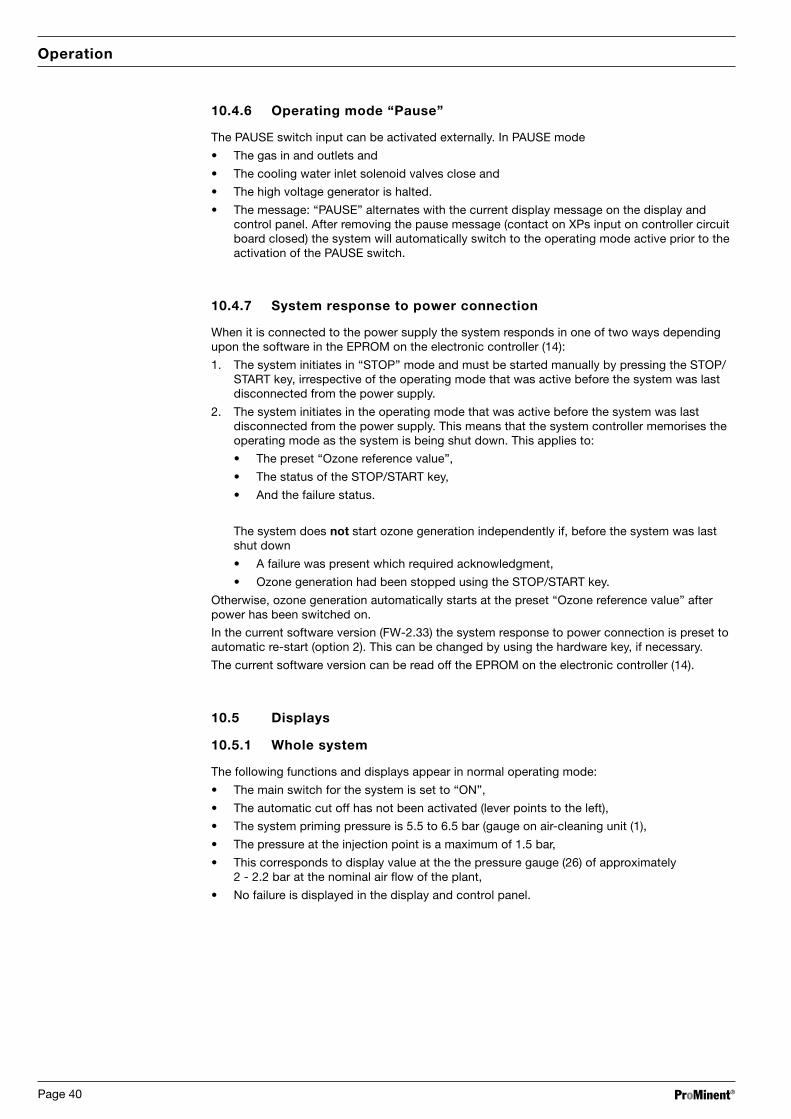
ProMinent®Page 40
Operation
10.4.6 Operating mode “Pause”
The PAUSE switch input can be activated externally. In PAUSE mode
• The gas in and outlets and
• The cooling water inlet solenoid valves close and
• The high voltage generator is halted.
• The message: “PAUSE” alternates with the current display message on the display andcontrol panel. After removing the pause message (contact on XPs input on controller circuitboard closed) the system will automatically switch to the operating mode active prior to theactivation of the PAUSE switch.
10.4.7 System response to power connection
When it is connected to the power supply the system responds in one of two ways dependingupon the software in the EPROM on the electronic controller (14):
1. The system initiates in “STOP” mode and must be started manually by pressing the STOP/START key, irrespective of the operating mode that was active before the system was lastdisconnected from the power supply.
2. The system initiates in the operating mode that was active before the system was lastdisconnected from the power supply. This means that the system controller memorises theoperating mode as the system is being shut down. This applies to:
• The preset “Ozone reference value”,
• The status of the STOP/START key,
• And the failure status.
The system does not start ozone generation independently if, before the system was lastshut down
• A failure was present which required acknowledgment,
• Ozone generation had been stopped using the STOP/START key.
Otherwise, ozone generation automatically starts at the preset “Ozone reference value” afterpower has been switched on.
In the current software version (FW-2.33) the system response to power connection is preset toautomatic re-start (option 2). This can be changed by using the hardware key, if necessary.
The current software version can be read off the EPROM on the electronic controller (14).
10.5 Displays
10.5.1 Whole system
The following functions and displays appear in normal operating mode:
• The main switch for the system is set to “ON”,
• The automatic cut off has not been activated (lever points to the left),
• The system priming pressure is 5.5 to 6.5 bar (gauge on air-cleaning unit (1),
• The pressure at the injection point is a maximum of 1.5 bar,
• This corresponds to display value at the the pressure gauge (26) of approximately2 - 2.2 bar at the nominal air flow of the plant,
• No failure is displayed in the display and control panel.

ProMinent® Page 41
Operation
10.5.2 Display and control panel
The information contained in the display and control panel (16) is displayed as shown below inthe menu option relating to setting the required “Ozone reference value”. More information, seechapter 10.6 “Control menu”.
Measured valueUnit of measured value
Normal operating: Displayed measured valuemode in case of failure: First cause of failure
Measured value status information:Display Operating mode for displayed value
Adjustable value mA Value can be adjusted
via external interface None Display value only
Failure display:Display Description None Normal operating mode ε Failure, system stopped ω Warning * Failure informationFlashing Reference value below 3 %
ozone setting
10.6 Control menu
10.6.1 Ozone reference value; internal operation
ozone setting
The required ozone value is set in percent in the “Ozone reference value” display. In internaloperating mode, settings are adjusted using the “UP” and “DOWN” keys. A 100 % referencevalue setting corresponds to the maximal ozone quantity (see Technical Data, chapter 13).
10.6.2 Ozone reference value; external operation
ozone setting
The required ozone value is set in percent in the “Ozone reference value” display. In externaloperating mode, settings are adjusted using a current interface connected to the XmA input. A20 mA reference value setting corresponds to a display value of 100 %.
10.6.3 Ozone quantity
ozone gen.rate
g/hThe display shows the current amount of ozone being generated in g/h.
The displayed value is calculated from measured electrical values and is corrected in relation tothe current measured value of the process airflow.
10.6.4 Gas flow
gasflow
m3/hThe display shows the current measured value of the gas flow through the ozone generator. Thedisplay value is related to Normal conditions (air pressure 1013.25 mbar, temperature 0 ºC).See Technical Data (chapter 13) for nominal process airflow.

ProMinent®Page 42
Operation
10.6.5 Primary current
prim. current
AThe display gives the current flowing on the primary side of the high voltage transformer. Thedisplayed measured value is dependent on the preset “Ozone reference value”.
10.6.6 Transformer voltage
prim. voltage
VThe display gives the voltage present on the primary side of the high voltage transformer. Thedisplayed measured value is dependent on the preset “Ozone reference value” and theoperating pressure displayed on the pressure gauge in the system cabinet (26).
10.6.7 Temperature
temperature
The display gives the mid temperature measured at the cooling water outlet of the ozonegenerator. The display is dependent on the “Ozone reference value” and the temperature of thecooling water inlet.
10.6.8 Internal/External
intern/extern
Here, the UP and DOWN keys are used to change the ozone quantity settings options:
0 = Internal: The ozone quantity can be set in % increments using the keypad,as described above, in the “Ozone reference value” display.
1 = External: The ozone quantity is set via a 0-20 mAor 4-20 mA current interface connected to the XmA input.
Any changes in operating mode are confirmed using the “Enter” key.
If the operating mode is changed, the system starts up in “Stop” mode and must be restartedby the operator.
10.6.9 0/4-20 mA
0/4-20mA
If the current interface was selected in the previous display for setting the ozone quantity, thisdisplay can be used to set the type of current interface:
0 = 0-20 mA - current interface
1 = 4-20 mA - current interface
Any changes in operating mode are confirmed using the “Enter” key.
10.6.10 Language
language
Setting required display language:
0 = German
1 = English
2 = French
3 = Spanish
4 = Italian
Only German and English are currently available. Changes to the language are confirmed usingthe “Enter” key.

ProMinent® Page 43
Operation / System Maintenance
10.6.11 Generator pressure
gen. pressure
This display is used to enter the pressure present in the installed system so that the ozonequantity can be precisely corrected in relation to this pressure. The pressure is read from thegauge (26) in the system cabinet.
The display value is altered using the UP and DOWN keys and confirmed using ENTER.
The value displayed when the system is first commissioned is the factory setting.
10.6.12 Operating parametersworking:ozone:power on:faults:
This display shows the following values:
� Working hours of the system with mains switched on.
� Working hours with ozone generation switched on.
� Number of mains switches (main switched on).
� Number of occured failures.
11 System Maintenance
Check the liquid levels in the containers on the air-cleaning unit on the outside of theOZONFILT® OZVa at regular intervals, at least once a week and more often if necessary. Thecontainer is normally emptied automatically. If condensate is visible, the relevant containershould be emptied by hand.
Check the filter elements (visible from outside the air cleaning unit) regularly, but at least once aweek. If they are obviously very dirty, the filter must be replaced.
TAKE CARE
If condensate is visible in the pipe that feeds from the air-cleaning unit into thesystem, the system must be automatically decommissioned and inspected byProMinent-authorised personnel. Check and maintain inlet filter of thecompressor in accordance with the operating instructions of the compressor, ifsupplied with the system.
Safety guidelines for maintenance activities
WARNING
All maintenance and repair work must be carried out by qualified personnel whohave been authorised by ProMinent.
Qualified personnel are persons who, as a result of specialised training andexperience, have sufficient knowledge in the field of ozone systems, and aresufficiently familiar with relevant national legislature on safety at work, accidentprevention, directives and general technical regulations to be able to correctlyjudge the safety conditions within an ozone system.
Interference from unauthorised personnel renders void all guarantees or liability claims on behalfof the operator.

ProMinent®Page 44
Troubleshooting
12 Troubleshooting
The failures described in the table below cause the system to shut down.
There are delays of varying lengths, depending upon the type of failure, between initial failurerecognition and system shut down, During the delay, a star flashes instead of the failure symbolin the lower right-hand corner of the LCD display. The system is switched off in stages:
� Firstly the high voltage is switched off. The system continues to run for approx. 6 secondslonger without generating ozone. During this period, the remaining ozone is extracted fromthe generator.
� Solenoid valves then pneumatically and hydraulically isolate the system (gas inlet, gasoutlet, cooling water inlet).
� A failure message appears in the display and control panel, giving the cause of the failure.
The failures highlighted in bold in the table below activate the fault indicating relay (XUSr) on thecontroller circuit board (see section 8.2 “Electrical In and Out puts”). These must beacknowledged, after remedying the fault, at the display and control panel. The ozone generatormust be restarted manually using the STOP/START key.
No. Shut down by Failure message Reason for shut down Commentsin the display and OZVa 4control panel
1 Safety system none Current consumption too high
2 Door trip switch none Door open
3 Gas detector ozone alarm!! Ozone gas leak
5 Flow monitor; cooling water cooling water � Cooling water flowbelow minimum level
6 Flow monitor, water � Flow of water for ozonising too low. Only if a flow monitor isprocess water The system starts up again when connected to the input
the cause of the problem has been XPD (X3:13,14)eliminated! The fault indicating relayon the controller circuit board isnot activated.
7 Gas flow monitor gasflow � Gas flow below lower limit
8 Monitoring of current current dyn.� Several consecutive excessivecurrent impulses.Defect in HV transformer orozone generator.
11 Ozone reference value setting none Ozone generator switched off when Operation stage withoutbelow 3 % ozone reference value is set high voltage
to values below 3 %
12 Gas flow monitor gasflow � Gas flow above upper limit
13 Electronic current meter prim. current � Current in HV transformer aboveupper limit
14 Electronic voltmeter transformer voltage � Voltage in HV transformer above Decrease pressure at theupper limit injection point to values
below 1.5 bar
15 Pt 100 temperature sensor in temperature � Temp. at cooling water outlet ofupper section of ozone ozone generator < 5 °Cgenerator temperature � Temp. at cooling water outlet of Increase cooling water flow
ozone generator > 45 °C or decrease cooling waterinlet temperature
16 Power supply for system dc voltage � Line voltage below 200 V,of fuse at power board (15) blown
dc voltage � Line voltage above 253 V

ProMinent® Page 45
Technical Data, Standards, Directives
13 Technical Data, Standards, Directives
13.1 Technical Data
System type:
OZONFILT® OZVa, ozone generating and metering system.
Compulsory accessories for swimming pool applications:
Reaction tank with ventilation equipment,
Filter with activated carbon layer and ventilation equipment,
Exhaust ozone gas destructor,
Ozone gas detector.
Plant room:
With mechanical ventilation (3-fold air change) and gas detector.
Ozone generating module
Type OZONFILT® Unit OZVa 4
Number of generator modules 2
Ozone output, measured inaccordance with DIN at air 20 ºC,cooling water: 15 ºC,flow rate: 70 l/h g/h 40
Max. humidity of surrounding air % 85,non-condensing
Max. ambient temperature °C 40
Airflow for ozone generation m³/h 2
Airflow for regeneration m³/h 0.5
Ozone concentration in the gasphase related to normal conditionsat full capacity g/m³ 20
Ozone connector G ¼" inside thread
Cooling water connector
Cooling water requirement m³/h 0.07 - 0.1
Cooling water inlet pressure bar < 5
Cooling water outlet Zero pres. outlet
Cooling water temperatureambient temp. < 35°C °C < 30
Cooling water temperatureambient temp 35 - 40°C °C < 25
PE delivery hose connector mm 6 x 4
Cooling water quality Drinking water,not desalinated
Air connector (air-cleaning unit)
Total air quantity Nm³/h 2.5
Process air quantity Nm³/h 2
Regenerating air quantity Nm³/h 0.5
Nominal operating pressure bar 5.5 - 6.5
Maximum pressure bar 10
Safety valve setting (system input) bar approx. 7
Safety valve setting (ozone generator) bar approx. 2.7

ProMinent®Page 46
Technical Data, Standards, Directives
Unit OZVa 4
Electrical connections
Typ. power consumption forozone generation kW < 0.8
Power factor cos f > 0.99,at full capacity
Mains power supply V / Hz 230 / 50 - 60
Enclosure rating IP 43
Switch input, pause (XPs) Isolated,load: +15 V/max. 10 mA
Switch input, ozone warning device(XOz) Isolated,
load: +12 V/max. 1.5 mA
Standard signal input,Ozone reference value (XmA) Isolated,
resistance: +1.7 V at +20 mAinput current
Alarm output (XUsr) Isolated, change-over230 V/max. 8 A, free contact
Mixing equipment module
Unit OZVa 4
Flow volume for OZVa xx4xX m³/h 10 - 15
Flow volume for OZVa xx5xX m³/h 15 - 25
Flow volume for OZVa xx6xX m³/h 25 - 35
Flow volume for OZVa xx7xX m³/h 35 - 50
Raw water connector for OZVa xx4xX DN 50
Raw water connector for OZVa xx5xX DN 65
Raw water connector for OZVa xx6xX DN 80
Raw water connector for OZVa xx7xX DN 100
Raw water temperature °C < 35
Pressure range in raw water pipe bar < 1.5
Total dimensions
Width (mm) 710
Height (mm) 1400
Depth (mm) 310
Weight (kg) 121
Compressor
Unit OZVa 4
Compressor mains power supply V / Hz 230 / 50 or 60
Average power consumptionat max. operating pressure, 50 Hz kW 1.02at 60 Hz for continous operation kW 1.59
Typical power consumption50 Hz kW 0.460 Hz kW 0.5

ProMinent® Page 47
Technical Data, Standards, Directives
13.2 Standards and Directives
System complies with DIN 19627 “Ozone Generators for Water Treatment”,as well as ZH 1/474 or GUV 18.13
“Directives for the Use of Ozone for Water Treatment.”
Applicable EU Guidelines:
The system is constructed in accordance with the following standards:
EU - Low Voltage directives (73/23/EWG)
EU - EMV - Directive 89/336/EWG i.d.F. 92/31/EWG
Related harmonised standards, in particular:
DIN EN 60204 - 1
EN 50081 - 1/2, EN 50082 - 1/2
EN 60555 - 2, EN 60553 - 3
Related national standards and other technical specifications, in particular:
E DIN 19627
DIN VDE 0110 T1 and T2
DIN VDE 0700 T1
VDE 0101
ZH1/474
13.3 Permissions/Approvals for the OZONFILT® OZVa
The system carries the CE symbol.

ProMinent®Page 48
Identity Code
t t t t t t
OZV a Ozone generating system
a Series version
Ozone quantity
1 5 g/h
2 15 g/h
3 35 g/h
4 40 g/h
Operating voltage
0 230 50/60 Hz
1 115 50/60 Hz
Mixing system
0 None
1 With mixer (flow 0.5 to 3 m³/h)
2 With mixer (flow 3 to 5 m³/h)
3 With mixer (flow 5 to 10 m³/h)
4 With mixer (flow 10 to 15 m³/h)
5 With mixer (flow 15 to 25 m³/h)
6 With mixer (flow 25 to 35 m³/h)
7 With mixer (flow 35 to 50 m³/h)
Compressor
0 None
1 With standard compressor*
2 With oil-free compressor for OZVa 5
* OZVa 1: oil-lubricated; OZVa 2, 3 and 4: oil-free
Language
D German
E English
OZV a _ _ _ _ _

ProMinent® Page 49
EC Declaration of Conformity