TOC Bookmark Limit switch attachments SRBE Limit ... - Festo

Operating Instructions Limit switch Types 07-2511…./…and 07-2581…./….
BARTEC GmbH Max-Eyth-Straße 16 D-97980 Bad Mergentheim
Tel.: +49 7931 597-0 Fax: +49 7931 597-119
[email protected] www.bartec.de
Reservation Technical data subject to change without notice. Changes, errors and misprints may not be used as a basis for any claim for damages.
1/4
Limit switch incl. actuator
Explosion protection Technical data
Description
These limit switches are used wherever safe and
reliable signal transmission is required. Areas of use include e.g. petrol pumps, pumps in general and the construction of machinery and instruments.
The standard version of the switch contains fine silver contacts. Gold-plated fine-silver contacts are
available for particularly low voltage and currents. As a basic rule, all contact elements have protective gold plating.
The connecting cable is cast in at the back. The
length of the connecting cable is variable.
The switching sequence in double-break switches
can be selected at will:
• Chambers I and II switch almost simultaneously
• Chamber I switches 0.03 to 0.3 mm before
chamber II.
Ex protection type
II 2G Ex d IIC T6
II 2D Ex tD A21 IP66 T80°C Ex d II C T6
0044
Certifications PTB 00 ATEX 1093 X IBExU 01 ATEX 1007 X IECEx PTB 07.0045X
Ambient temperature -20 °C to +40 °C -55 °C to +75 °C on request
Approved for Zones 1 and 2, 21 and 22
Current carrying capacity 7 A (single-pole) /6 A (double-pole) at 60 °C 3 A (single-pole) /2 A (double-pole) at 75 °C
01-250
0-7D
0001-A.01-BARTECAdvertisingA
gency-279811E
Dimensions in mm Anrastöffnungen = clip-on pockets, Hebelbreiten = lever widths, Einfachschalter = single-break switch, Doppelschalter = double-break switch
X
ø 3
,2
4
46
,2
8,1
5,9
Anrastöffnung
Hebelbreiten
X
Y
Y
9
5°
5°
3,3
5
9
5°
5°
3,3
5
19
9,5
0,5
5,1
0,8
25,5
15,8
5
11,3
5
Doppels
chalter
Ein
fachschalter
6
Rated voltage/current AC 400 V, 2 A (AC-15) DC 250 V, 0,15 A (DC-13)
Protection class IP 66 (EN 60529)
Contact options 1 and 2 changeover contacts resp. or 1 NC contact and/or 1 NO contact NC and NO contacts at same voltage potential
Weight (with 3-metre cable) 210 g (single-break switches) 415 g (double-break switches)
Tightening torques Fixing screws: max. 0.6 Nm
Switching rate max. 1000/h
Switching actuation force max. 2.0 N (single-break switch) max. 3.6 N (double-break switch)
Reset force min. 0.4 N (single-break switch) min. 0.8 N (double-break switch)
Contact travel Pretravel VLW: max. 0.9 mm Overtravel NLW: min. 0.5 mm Reset travel RLW: 0.9 mm Differential DW: max. 0.45 mm Free travel LLW: 0,1 to 0.45 mm
Service life Mechanical:> 2 x 10⁶ switching cycles Electrical: depending on load
Enclosure material Plastic (thermoplastic)
Plunger/additional actuator Stainless steel
Electrical connecton See data sheet
Operating Instructions Limit switch Types 07-2511…./…and 07-2581…./….
BARTEC GmbH Max-Eyth-Straße 16 D-97980 Bad Mergentheim
Tel.: +49 7931 597-0 Fax: +49 7931 597-119
[email protected] www.bartec.de
Reservation Technical data subject to change without notice. Changes, errors and misprints may not be used as a basis for any claim for damages.
2/4
01-250
0-7D
0001-A.01-BARTECAdvertisingA
gency-279811E
Safety Instructions
The limit switch may be used only within the specified temperature range.
Unprotected, incorrect installation can cause malfunctioning and the loss of explosion protection.
The limit switch may be connected and mounted only by qualified personnel who are authorised and trained to assemble electric components in hazardous (potentially explosive) areas.
Always disconnect the limit switch from voltage before assembly or disassembly.
Utilisation in areas other than those specified or the modification of the product by anyone other than the manufacturer will exempt BARTEC from liability for defects or any further liability.
The generally applicable statutory rules and other binding directives relating to workplace safety, accident prevention and environmental protection must be adhered to.
The limit switch may be operated only if it is clean and not damaged in any way.
The switch must be replaced after any short circuit that occurs in the main circuit because the switch is a piece of encapsulated equipment and it is therefore not possible to check the state of the switch contacts.
Marking
Particularly important points in these instructions are marked with a symbol:
DANGER
Non-observance leads to death or serious physical injury. The necessary safety measures must be taken.
CAUTION
Warning of damage to property and financial and penal disadvantages (e.g. loss of guarantee rights, liability etc.).
ATTENTION
Important instructions and information on preventing disadvantageous behaviour.
NOTE
Important instructions and information on effective, economical and environmentally compatible handling.
Standards conformed to
EN 60079-0:2006 EN 60079-1:2007 EN 61241-0: 2006 EN 61241-1:2004 IEC 60079-0:2004 IEC 60079-1:2007 EN 60947-1 :2007 EN 60947-5-1 :2004
Assembly and Commissioning
ATTENTION
Only authorised and qualified personnel may do any of the assembly, disassembly, installation and commissioning work.
CAUTION
The relevant installation and operating regulations must be observed when setting up or operating explosion-proof electric systems.
Before mounting it, check that the limit switch is in perfect condition.
Assembly/disassembly
CAUTION
The limit switch must be so fitted in a way that ensures that it will be mechanically protected.
If the switches are mounted outdoors, they may need to be fitted into an outer enclosure with an adequate protection class.
Only suitable tools may be used for installation work.
Installation
CAUTION
During installation take care not to damage the Individual wires in conductors. The ends on fine-stranded and multi-stranded conductors must be prepared. Wire end ferrules must be crimped with suitable crimping tools.
The quality of the connection-cable has to be so chosen that it meets the thermal and mechanical requirements in the field of application.
Commissioning
Before commissioning check that:
• The device has been installed correctly
• the device is not damaged
• that there is no foreign matter obstructing the actuating travel
• the junction box is clean
• the connection has been made properly
• the cables have been laid correctly
• all screws are tightened securely
NOTE
The types of contacts and cable markings can be found on the following page. The actuator variants are listed in the data sheet.
Operation
DANGER
The limit switch may be operated only within the technical limits that apply to it (see Explosion Protection and Technical Data sections).
CAUTION
It is not permissible to technically modify the switch.
Maintenance and Fault Clearance
The operator of the limit switch has to must keep it in good condition, operate it properly, monitor it and clean it regularly. The limit switch enclosure must be checked regularly for cracks and damage.
NOTE
Dirty switches/actuators can be cleaned with compressed air.
The limit switch is defective if the switching unit does not perform switching functions or the actuator does not activate the switching unit any longer. Defective limit switches cannot be repaired; they must be replaced.
Accessories, Spare Parts
For connection in Ex areas, BARTEC offers a wide range of terminal boxes.
Disposal
The components in the switch module contain metal and plastic parts.
The statutory requirements for disposing of electronic scrap must be observed therefore (e.g. disposal by an approved disposal company).
Service address
BARTEC GmbH Max-Eyth-Straße 16 D-97980 Bad Mergentheim Tel.: +49 7931 597-0 Fax: +49 7931 597-119

Operating Instructions Limit switch Types 07-2511…./…and 07-2581…./….
BARTEC GmbH Max-Eyth-Straße 16 D-97980 Bad Mergentheim
Tel.: +49 7931 597-0 Fax: +49 7931 597-119
[email protected] www.bartec.de
Reservation Technical data subject to change without notice. Changes, errors and misprints may not be used as a basis for any claim for damages.
3/4
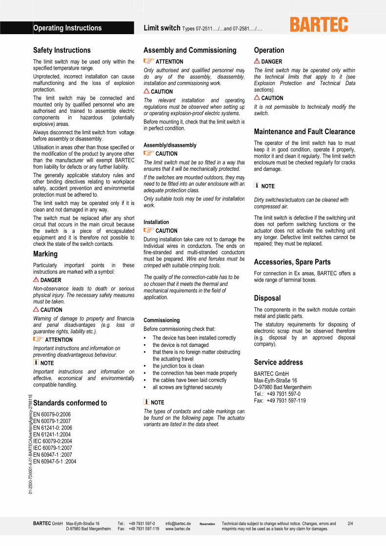
Assembly
max. 0,6 Nm
2 x
Connection single-break switch Connection double-break switch
BU
BN BN
BU
BK
GY BN
BU
BN GY
BK
BK
GY
GY
BK
1
2 3BN
BU
BN
BU
GY
BK
BN
BU
4
5 6
01-250
0-7D
0001-A.01-BARTECAdvertisingA
gency-279811E
Key
BK = black core
BN = brown core
BU = blue core
GY = grey core

Operating Instructions Limit switch Types 07-2511…./…and 07-2581…./….
BARTEC GmbH Max-Eyth-Straße 16 D-97980 Bad Mergentheim
Tel.: +49 7931 597-0 Fax: +49 7931 597-119
[email protected] www.bartec.de
Reservation Technical data subject to change without notice. Changes, errors and misprints may not be used as a basis for any claim for damages.
4/4
01-250
0-7D
0001-A.01-BARTECAdvertisingA
gency-279811E