Operating Instructions - · PDF filethat it is approved by ASTA or BSI to BS1362. ......
11
64-CHANNEL INTEGRATED AMPLIFIER Operating Instructions P/N: SU-MED640E Panasonic
Transcript of Operating Instructions - · PDF filethat it is approved by ASTA or BSI to BS1362. ......

64-CHANNEL INTEGRATED AMPLIFIER
Operating Instructions
P/N: SU-MED640E
Panasonic

Caution for AC main lead
FOR YOUR SAFETY, PLEASE READ THE FOLLOWING TEXT CAREFULLYThis product is equipped with 2 types of AC main cable. One is for continental Europe, etc. and the otherone is only for UK. Appropriate main cable must be used in each local area, since the other type of maincable is not suitable.
FOR UK ONLYThis appliance is supplied with a moulded three pin mains plug for your safety and convenience.A 13 amp fuse is fitted in this plug. Please ensure that the replacement fuse has a rating of 13 amps andthat it is approved by ASTA or BSI to BS1362.Check for the ASTA mark or the BSI mark on the body of the fuse.If the plug contains a removable fuse cover you must ensure that it is refitted when the fuse is replaced. Ifyou lose the fuse cover the plug must not be used until a replacement cover is obtained. A replacementfuse cover can be purchased from your local Panasonic Dealer.
How to replace the fuse(1) Open the fuse compartment with a screwdriver.
(2) Replace the fuse.
FOR CONTINENTAL EUROPE, ETC. FOR UK ONLY

Safety Precautions
Before using this unit please read these operating instructions carefully. Take special care to follow thewarnings indicated on the unit itself as well as the safety suggestions listed below. Keep these precau-tions handy for future reference.
The unit may be used only in the operating conditions and positions specified manufacturer.Unless otherwise agreed the following applies to this unit. 1. Pollution category: II (Indoor use only) 2. Installation over voltage category: II 3. Altitude: max.2,000 m
PlacementAvoid placing the unit in areas of: - direct sunlight - high temperature - high humidity - excessive vibration - uneven surfaces (Place the unit on a flat level surface.)Such conditions might damage the cabinet and/or other component parts and thereby shorten the unit'sservice life.
StackingNever place heavy items on top of the unit or the AC power cord.
Voltage- It is very dangerous to use a "high voltage" AC power source such as for an air conditioner. A fire might
be caused by such a connection.- A DC power source can not be used. Be sure to check the power source carefully.
Power cord protection- Avoid using AC power cords with cuts, scratches, or poor connectors, as this may result in fire or electric
shock. Excessive bending, pulling or slicing of the cord should also be avoided.- Do not pull on the cord when you are disconnecting the power, as this could cause an electric shock.
Grasp the plug firmly when you disconnect the power supply.- Never touch the plug with wet hands or a serious electric shock could result.
Foreign Materials- Ensure that no foreign objects (e.g. - needles, coins, screwdrivers), accidentally fall into the unit. Other-
wise, a serious electric shock or malfunction could occur.- Be extremely careful about spilling water or liquid on or into the unit, as a fire or electric shock could
occur (Disconnect the power plug and contact your dealer immediately if this occurs).- Avoid spraying volatile chemicals (e.g.- insecticides, alcohol, paint thinner) on or into the unit as they
contain flammable gases which can be ignited.- Insecticides, alcohol, paint thinner and similar chemicals should never be used to clean the unit as they
can cause flaking or cloudiness to the cabinet finish.
3

Service- Never attempt to repair, disassemble or modify the unit if there seems to be a problem. A serious electric
shock could result if you ignore this precautionary measure.- If a problem occurs during operation (smoke is detected, etc.) contact your dealer immediately.- Disconnect the power supply if the unit will not be used for a long time. Otherwise the operation life could
be shortened.
Safety-related symbols used on equipment and documentation:
Environmental conditions- Indoor use.- Altitude up to 2000 m.- Temperature: 5 - 40 C.- Maximum relative humidity 80% for temperatures up to 31 C decreasing linearly to 50% relative humidityat 40 C.- Mains supply voltage fluctuations not to exceed +/- 10% of the nominal voltage.
MaintenanceClean the cabinet, panel and controls with a soft cloth lightly moistened with mild detergent solution.Do not use any type of abrasive pad, scouring power or solvent such as alcohol or benzine.
Fuse (F1)Rating: T315 mA
Frame or chassisTERMINAL
4

Components and their functions
Front panel
(1) POWERTo turn the amplifier on and off.Caution: Do NOT turn on the power with a "mini-plug" connected on the output terminal of the internal stimulators
(#2, 3, 4 & 5). This may cause damage to the microelectrode(s) on the probe.(2) OUTPUT INT(V) [CH1]
The output terminal for the variable, internal channel 1 (CH1) constant current stimulator. The amplitude of thecurrent delivered is variable (V) and can be adjusted with dial (6)*1.
(3) OUTPUT INT(F) [CH1]The output terminal for the fixed, internal channel 1 (CH1) constant current stimulator. The amplitude of the cur-rent delivered is fixed (F) and set on the computer*1.
(4) OUTPUT INT (V) [CH2]The output terminal for the variable, internal channel 2 (CH2) constant current stimulator. The amplitude of thecurrent delivered is variable (V) and can be adjusted with dial (7)*1.
(5) OUTPUT INT(F) [CH2]The output terminal for the fixed, internal channel 2 (CH2) constant current stimulator. The amplitude of the cur-rent delivered is fixed (F) and set on the computer*1.
(6) AMPLITUDE [CH1]This 'potentiometer' is used to adjust the output amplitude for the variable, CH1 stimulator (2). The initial(x1)amplitude, which is set in the computer software, can be adjusted in 0.1 steps between 0 and 10 times.
(7) AMPLITUDE [CH2]This 'potentiometer' is used to adjust the output amplitude for the variable, CH2 stimulator (4). The initial(x1)amplitude, which is set in the computer software, can be adjusted in 0.1 steps between 0 and 10 times.
(8) OUTPUT EXT [CH3]The output terminal for an external stimulus isolation unit (see page 4)*2,*3.
(9) OUTPUT EXT [CH4]The output terminal for an external stimulus isolation unit (see page 4)*2,*3.
(10) INPUT EXT [CH3]The input terminals (+ & -) for an external stimulus isolation unit.
(11) INPUT EXT [CH4]The input terminals (+ & -) for an external stimulus isolation unit.
(12) ELECTRODE SELECTORThe terminal(s) used to select the stimulus electrodes on the MED probe. Use a MED64 mini-plug to connect toeither terminals (2) through (5) or terminals (8) and (9).
*1 The internal stimulus amplifier in this unit delivers constant current pulses between the electrode selected withELECTRODE SELECTOR (12) and the reference electrodes (see page 5).
*2 The external stimulus isolation unit(s) can be used to deliver monopolar pulses (mono-phasic or bi-phasic) pulsesbetween one of the 64 electrodes and the reference electrodes (as is the case for the internal stimulators). In thisscenario, the MED64 mini-plug is connected between the + or - output terminal and one probe electrode of yourchoice using the Electrode Selector panel (12).
*3 The external stimulus isolation unit(s) can also be used to deliver true bipolar pulses between 2 electrodes of yourchoice from the 64 available points.
5

Back Panel
(13) INPUTTo connect to the MED probe, through the MED-CO3 connector, to the amplifier.
(14) OUTPUT(1-32CH)To connect the output of channels 1-32 to the to the first A/D board in the computer.
(15) OUTPUT(33-64CH)To connect the output of channels 33-64 to the to the second A/D board in the computer.
(16) SIGNAL OUTPUTBNC connectors used to send analog outputs from selected recording channels to an external amplifier, signalprocessor, or other device (e.g. - oscilloscope).
(17) STIMULUS EXT 1To connect to an external stimulus isolation unit. Outputs the EXT 1 trigger pulse from the computer to the exter-nal stimulator.
(18) STIMULUS EXT 2To connect to an external stimulus isolation unit. Outputs the EXT 2 trigger pulse from the computer to the exter-nal stimulator.
(19) OPERATION INA port of input trigger signals from the external components.
(20) OPERATION OUTA port of output trigger signals to the external components.
(21) SIGNAL GNDA ground terminal for signals.
(22) ~ AC INInsert the AC power supply cord here.
Reference Electrodes
To optimize the signals from all 64 electrodes as recording/stimulating electrodes, reference electrodeshave been added. This allows differential recording to be made between each channel and referenceelectrodes. It also optimizes the delivery of mono-polar stimuli, as they are delivered between the chosen(recording) electrode and the reference electrodes.
MED probe Reference electrodes
6

Connection to other components
Usage of internal stimulus amplifier(Components and cables indicated with dashed lines are not included)
MED Connector
A/D board cables(NI SH-100100)
Connector cable (included)
A/D board in PC(NI PCI-6071E)
A/D board in PC(NI PCI-6071E)
7

Using the MED64 amplifier with External Devices (stimulator, isolator, oscilloscope).
Caution: Do NOT connect MED64 mini-plugs on the internal stimulator outputs (CH1 or CH2).(Components and cables indicated with dashed lines are not included.)
External StimulatorExternal Isolator
External StimulatorExternal Isolator
BNC cables
BNC cables
BNC cables
A/D board cables(NI SH-100100)
A/D board in PC(NI PCI-6071E)
A/D board in PC(NI PCI-6071E)
MED Connector
Connector cable (included)
Oscilloscope
8

Precautions during use
Always, turn ON the amplifier power BEFORE starting up the software. The software sends information tothe Amplifier that is necessary for initialization of stimuli and the recorded data. Failure to do so (i.e. turn-ing ON power to the amplifier after the software starts up) will lead to inaccuracies in stimulus delivery andthe data recorded.
Included accessories
Warranty
This product will be repaired with new or refurbished parts, free of charge, for one (1) year from the dateoriginal purchase in the event of a defect in materials or workmanship.
The product warranty covers failures due to defects in materials or workmanship which occur during nor-mal use. It does NOT cover damage which occurs in shipment or failures which are caused by productsnot supplied by AMS. In addition, this warranty does not cover failures resulting with results from alter-ation, accident, misuse, neglect, faulty installation, maladjustment of user controls, improper mainte-nance, modifications or service by anyone other than AMS or damage that is attributable to acts of God.
Please refer attached warranty card in detail.
Information on Disposal for Users of Waste Electrical & Elec-tronic Equipment (private households)
This symbol on the products and/or accompanying documents means that used electri-cal and electronic products should not be mixed with general household waste.For proper treatment, recovery and recycling, please take these products to designatedcollection points, where they will be accepted on a free of charge basis. Alternatively, insome countries you may be able to return your products to your local retailer upon thepurchase of an equivalent new product. Disposing of this product correctly will help to save valuable resources and prevent anypotential negative effects on human health and the environment which could otherwise
arise from inappropriate waste handling. Please contact your local authority for further details of yournearest designated collection point.Penalties may be applicable for incorrect disposal of this waste, in accordance with national legislation.
For business users in the European UnionIf you wish to discard electrical and electronic equipment, please contact your dealer or supplier for furtherinformation.
Power supply cord (1 pc.)Connector cable (1 pc.)
Mini-mini-cord(4 pcs.)
9
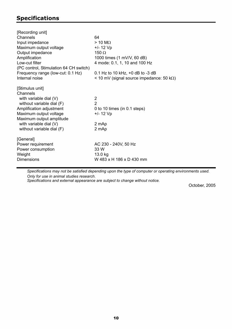
Specifications
Specifications may not be satisfied depending upon the type of computer or operating environments used.Only for use in animal studies research.Specifications and external appearance are subject to change without notice.
October, 2005
[Recording unit]Channels 64Input impedance > 10 MΩMaximum output voltage +/- 12 VpOutput impedance 150 ΩAmplification 1000 times (1 mV/V, 60 dB)Low-cut filter(PC control, Stimulation 64 CH switch)
4 mode: 0.1, 1, 10 and 100 Hz
Frequency range (low-cut: 0.1 Hz) 0.1 Hz to 10 kHz, +0 dB to -3 dBInternal noise < 10 mV (signal source impedance: 50 kΩ)
[Stimulus unit]Channels with variable dial (V) 2 without variable dial (F) 2Amplification adjustment 0 to 10 times (in 0.1 steps)Maximum output voltage +/- 12 VpMaximum output amplitude with variable dial (V) 2 mAp without variable dial (F) 2 mAp
[General]Power requirement AC 230 - 240V, 50 HzPower consumption 33 WWeight 13.0 kgDimensions W 483 x H 186 x D 430 mm
10

RQT5390-B
Matsushita Electric Industrial Co., LTD.1-4 Matsuo-cho, Kadoma, Osaka 571-8505 Japan