Operating Instructions Cerabar M PMC41/45, … · BA201P/00/EN/04.10 71113268 Valid from software...
44
BA201P/00/EN/04.10 71113268 Valid from software version: 1.1/1.2 Operating Instructions Cerabar M PMC41/45, PMP41/45/46/48 Process pressure measurement 1 2 + – 3 Zero Damping on off Span Display 0,753 I O
Transcript of Operating Instructions Cerabar M PMC41/45, … · BA201P/00/EN/04.10 71113268 Valid from software...
BA201P/00/EN/04.10
71113268
Valid from software version:
1.1/1.2
Operating Instructions
Cerabar M PMC41/45, PMP41/45/46/48Process pressure measurement
1 2
+ –
3
ZeroDamping
on off
Span
Display
0,753
IO

Overview of documentation Cerabar M HART
2 Endress+Hauser
Overview of documentation
Device Documentation Contents
Cerabar M 4 to 20 mA HART Technical Information TI399P Technical data
Operating Instructions BA201P – Identification
– Installation
– Wiring
– Operation
– Commissioning
– Maintenance
– Troubleshooting and spare parts
– Appendix: illustration of menus

Cerabar M HART Table of contents
Endress+Hauser 3
Table of contents
1 Safety instructions . . . . . . . . . . . . . . . . 4
1.1 Designated use . . . . . . . . . . . . . . . . . . . . . . . . . . . . 4
1.2 Installation, commissioning and operation . . . . . . . . 4
1.3 Operational safety . . . . . . . . . . . . . . . . . . . . . . . . . . 4
1.4 Notes on safety conventions and icons . . . . . . . . . . . 5
2 Identification . . . . . . . . . . . . . . . . . . . . 6
2.1 Device designation . . . . . . . . . . . . . . . . . . . . . . . . . 6
2.2 Scope of delivery . . . . . . . . . . . . . . . . . . . . . . . . . . . 8
2.3 CE mark, Declaration of Conformity . . . . . . . . . . . . 8
2.4 Registered trademarks . . . . . . . . . . . . . . . . . . . . . . . 8
3 Installation . . . . . . . . . . . . . . . . . . . . . . 9
3.1 Incoming acceptance and storage . . . . . . . . . . . . . . . 9
3.2 Installation conditions . . . . . . . . . . . . . . . . . . . . . . . 9
3.3 Installation instructions . . . . . . . . . . . . . . . . . . . . . . 9
3.4 Post-installation check . . . . . . . . . . . . . . . . . . . . . . 17
4 Wiring . . . . . . . . . . . . . . . . . . . . . . . . 18
4.1 Connecting the device . . . . . . . . . . . . . . . . . . . . . . 18
4.2 Connecting the DXR375 handheld terminal . . . . . . 20
4.3 Connecting Commubox FXA191/FXA195 . . . . . . . 21
4.4 Connecting the measuring unit . . . . . . . . . . . . . . . 21
4.5 Potential equalization . . . . . . . . . . . . . . . . . . . . . . 22
4.6 Post-connection check . . . . . . . . . . . . . . . . . . . . . . 22
5 Operation . . . . . . . . . . . . . . . . . . . . . . 23
5.1 Onsite display (optional) . . . . . . . . . . . . . . . . . . . . 23
5.2 Operating elements . . . . . . . . . . . . . . . . . . . . . . . . 24
5.3 Operation via Endress+Hauser operating program . 25
5.4 Operation via Universal HART Communicator DXR375
26
6 Commissioning. . . . . . . . . . . . . . . . . . 27
6.1 Function check . . . . . . . . . . . . . . . . . . . . . . . . . . . 27
6.2 Onsite commissioning . . . . . . . . . . . . . . . . . . . . . 27
6.3 Commissioning via communication . . . . . . . . . . . 29
6.4 Locking/unlocking operation . . . . . . . . . . . . . . . . . 33
6.5 Information on the measuring point . . . . . . . . . . . 33
7 Maintenance. . . . . . . . . . . . . . . . . . . . 34
7.1 Exterior cleaning . . . . . . . . . . . . . . . . . . . . . . . . . . 34
8 Troubleshooting . . . . . . . . . . . . . . . . . 34
8.1 Fault . . . . . . . . . . . . . . . . . . . . . . . . . . . . . . . . . . . 34
8.2 Warning . . . . . . . . . . . . . . . . . . . . . . . . . . . . . . . . 35
8.3 Error codes in V2H0 and V2H1 . . . . . . . . . . . . . . . 35
8.4 Current simulation . . . . . . . . . . . . . . . . . . . . . . . . 36
8.5 Reset . . . . . . . . . . . . . . . . . . . . . . . . . . . . . . . . . . . 36
8.6 Repair . . . . . . . . . . . . . . . . . . . . . . . . . . . . . . . . . . 37
8.7 Repair of Ex-certified devices . . . . . . . . . . . . . . . . . 38
8.8 Spare Parts . . . . . . . . . . . . . . . . . . . . . . . . . . . . . . 39
8.9 Return . . . . . . . . . . . . . . . . . . . . . . . . . . . . . . . . . . 40
8.10 Disposal . . . . . . . . . . . . . . . . . . . . . . . . . . . . . . . . . 40
8.11 Software history . . . . . . . . . . . . . . . . . . . . . . . . . . . 40
9 Technical data . . . . . . . . . . . . . . . . . . . 40
10 Operating matrix . . . . . . . . . . . . . . . . . 41
Index . . . . . . . . . . . . . . . . . . . . . . . . . . . . . . 42

Safety instructions Cerabar M HART
4 Endress+Hauser
1 Safety instructions
1.1 Designated use
The Cerabar M is a pressure transmitter for measuring pressure and level.
The manufacturer accepts no liability for damages resulting from incorrect use or use other than that
designated.
1.2 Installation, commissioning and operation
The device is designed to meet state-of-the-art safety requirements and complies with applicable
standards and EC regulations. If used incorrectly or for anything other than the designated use, the
device can, however, be a source of danger e.g. product overflow due to incorrect installation or
configuration. Consequently, installation, connection to the electricity supply, commissioning,
operation and maintenance of the measuring system must be carried out by trained, qualified
specialists authorized to perform such work by the facility's owner-operator. The specialists must
have read and understood these Operating Instructions and must follow the instructions they
contain. Modifications and repairs to the device are permissible only if they are expressly approved
in the manual. Pay particular attention to the information and instructions on the nameplate.
1.3 Operational safety
1.3.1 Hazardous areas (optional)
Devices for use in hazardous areas are fitted with an additional nameplate (see from Page 6,
Section 2.1.1 "Nameplates"). If the measuring system is to be used in hazardous areas, applicable
national standards and regulations must be observed. The device is accompanied by separate
"Ex documentation", which is an integral part of this documentation. The installation regulations,
connection values and safety instructions listed in this Ex document must be observed. The
documentation number of the related safety instructions is also indicated on the additional
nameplate.
• Ensure that all personnel are suitably qualified.

Cerabar M HART Safety instructions
Endress+Hauser 5
1.4 Notes on safety conventions and icons
In order to highlight safety-specific or alternative operating procedures in the manual, the following
conventions have been used, each indicated by a corresponding icon in the margin.
Symbol Meaning
#Warning!
A warning highlights actions or procedures which, if not performed correctly, will lead to
serious personal injury, a safety hazard or the destruction of the device.
"Caution!
A caution highlights actions or procedures which, if not performed correctly, may lead to
personal injury or the incorrect operation of the device.
!Note!
A note highlights actions or procedures which, if not performed correctly, can have an
indirect effect on operation or trigger an unexpected response on the part of the device.
0Explosion-protected, type-examined equipment
If the device has this symbol embossed on its nameplate, it can be used in a hazardous area
or a non-hazardous area, depending on the approval.
-Hazardous area
Symbol used in drawings to indicate hazardous areas.
– Devices used in hazardous areas must possess an appropriate type of protection.
. Safe area (non-hazardous area)
Symbol used in drawings to indicate non-hazardous areas.
– Devices used in hazardous areas must possess an appropriate type of protection. Cables
used in hazardous areas must meet the necessary safety-related characteristic quantities.
% Direct current
A terminal to which DC voltage is applied or through which direct current flows.
&Alternating current
A terminal to which alternating voltage (sine-wave) is applied or through which alternating
current flows.
)Ground connection
A grounded terminal which, as far as the operator is concerned, is grounded by means of a
grounding system.
* Protective ground terminal
A terminal which must be connected to ground prior to establishing any other connections.
+Equipotential connection
A connection that has to be connected to the plant grounding system: this may be a
potential equalization line or a star grounding system depending on national or company
codes of practice.

Identification Cerabar M HART
6 Endress+Hauser
2 Identification
2.1 Device designation
2.1.1 Nameplates
! Note!
• The MWP (maximum working pressure) is specified on the nameplate. This value refers to a
reference temperature of 20°C (68°F), or a temperature of 100°F for ANSI flanges.
• The pressure values permitted at higher temperatures can be found in the following standards:
– EN 1092-1: 2001 Tab. 181)
– ASME B 16.5a – 1998 Tab. 2-2.2 F316
– ASME B 16.5a – 1998 Tab. 2.3.8 N10276
– JIS B2230
• The test pressure corresponds to the overpressure limit (OPL) of the device = MWP x 1.52).
• The Pressure Equipment Directive (EC Directive 97/23/EC) uses the abbreviation "PS". The
abbreviation "PS" corresponds to the MWP (maximum working pressure) of the measuring
device.
Nameplate of the aluminum housing
P01-PMx4xF18-18-xx-xx-xx-000
Fig. 1: Nameplate for Cerabar M with aluminium housing
➀ Order code
See the specifications on the order confirmation for the meanings of the individual letters and digits.
➁ Serial number
➂ Nominal measuring range
➃ Minimum/maximum span
➄ MWP (Maximum working pressure)
➅ Electronic version (output signal)
➆ Supply voltage
➇ Wetted materials
➈ Wetted materials
➉ Wetted materials
Maximum pressure for oxygen applications (optional for devices, suitable for oxygen applications)
Maximum temperature for oxygen applications (optional for devices, suitable for oxygen applications)
ID number of notified body with regard to Pressure Equipment Directive (optional)
ID number of notified body with regard to ATEX (optional)
SIL-symbol for devices with SIL2/IEC 61508 Declaration of conformity (optional)
Degree of protection
CRN number (optional)
1) With regard to their stability-temperature property, the materials 1.4435 and 1.4404 are grouped together under 13EO in EN 1092-1 Tab. 18. The chemical
composition of the two materials can be identical.
2) The equation does not apply for PMP41, PMP45 and PMP48 with a 100 bar measuring cell.
p
Mat.
Order Code:
Ser.-No.:
SpanM.W.P.:
Bei Sauerstoffeinsatzfor oxygen service
D-79689 MaulburgCerabar MMade in Germany,
1
15
23
4
67
10
1112
13
14
5
1617
89
5
6
7
Cerabar M HART Identification
Endress+Hauser 7
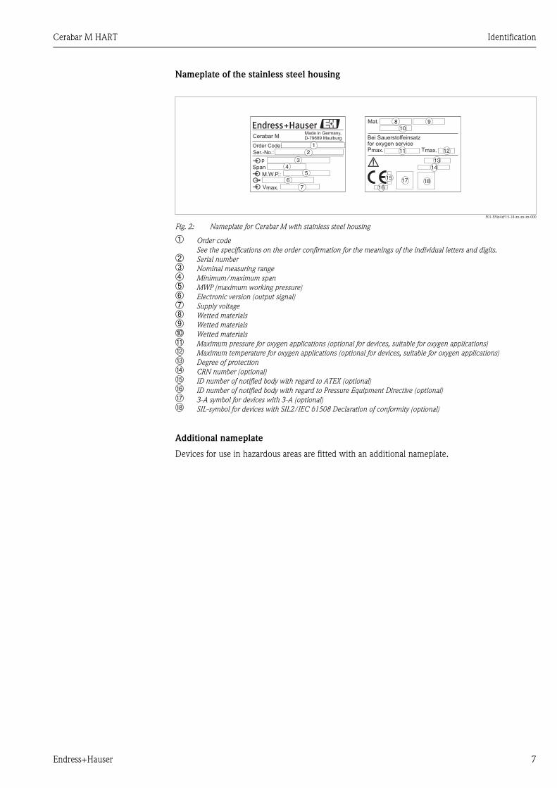
Nameplate of the stainless steel housing
P01-PMx4xF15-18-xx-xx-xx-000
Fig. 2: Nameplate for Cerabar M with stainless steel housing
➀ Order code
See the specifications on the order confirmation for the meanings of the individual letters and digits.
➁ Serial number
➂ Nominal measuring range
➃ Minimum/maximum span
➄ MWP (maximum working pressure)
➅ Electronic version (output signal)
➆ Supply voltage
➇ Wetted materials
➈ Wetted materials
➉ Wetted materials
Maximum pressure for oxygen applications (optional for devices, suitable for oxygen applications)
Maximum temperature for oxygen applications (optional for devices, suitable for oxygen applications)
Degree of protection
CRN number (optional)
ID number of notified body with regard to ATEX (optional)
ID number of notified body with regard to Pressure Equipment Directive (optional)
3-A symbol for devices with 3-A (optional)
SIL-symbol for devices with SIL2/IEC 61508 Declaration of conformity (optional)
Additional nameplate
Devices for use in hazardous areas are fitted with an additional nameplate.
p
Order Code:
Ser.-No.:
Span
M.W.P.:
D-79689 MaulburgCerabar MMade in Germany,
Mat.
Bei Sauerstoffeinsatzfor oxygen service
15
12
34
67
10
11 12
1314
5
1617 18
8 9
5
6
7
8

Identification Cerabar M HART
8 Endress+Hauser
2.2 Scope of delivery
The scope of delivery comprises:
• Cerabar M pressure transmitter
• Optional accessories
Documentation supplied:
• Operating Instructions BA201P (this document)
• Final inspection report
• Optional: factory calibration certificate
• Devices that are suitable for use in hazardous areas:
additional documentation such as Safety Instructions, Control or Installation Drawings
2.3 CE mark, Declaration of Conformity
The devices are designed to meet state-of-the-art safety requirements, have been tested and left the
factory in a condition in which they are safe to operate. The devices comply with the applicable
standards and regulations as listed in the EC Declaration of Conformity and thus comply with the
statutory requirements of the EC Directives. Endress+Hauser confirms the successful testing of the
device by affixing to it the CE mark.
2.4 Registered trademarks
KALREZ, VITON, TEFLON
Registered trademarks of E.I. Du Pont de Nemours & Co., Wilmington, USA
TRI-CLAMP
Registered trademark of Ladish & Co., Inc., Kenosha, USA
HART
Registered trademark of the HART Communication Foundation, Austin, USA
GORE-TEX®
Registered trademark of W.L. Gore & Associates, Inc., USA
Cerabar M HART Installation
Endress+Hauser 9
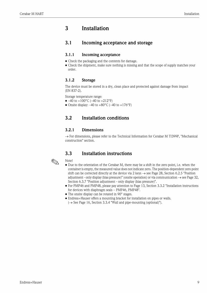
3 Installation
3.1 Incoming acceptance and storage
3.1.1 Incoming acceptance
• Check the packaging and the contents for damage.
• Check the shipment, make sure nothing is missing and that the scope of supply matches your
order.
3.1.2 Storage
The device must be stored in a dry, clean place and protected against damage from impact
(EN 837-2).
Storage temperature range:
• –40 to +100°C (–40 to +212°F)
• Onsite display: –40 to +80°C (–40 to +176°F)
3.2 Installation conditions
3.2.1 Dimensions
For dimensions, please refer to the Technical Information for Cerabar M TI399P, "Mechanical
construction" section.
3.3 Installation instructions
! Note!
• Due to the orientation of the Cerabar M, there may be a shift in the zero point, i.e. when the
container is empty, the measured value does not indicate zero. The position-dependent zero point
shift can be corrected directly at the device via 2 keys see Page 28, Section 6.2.5 "Position
adjustment - only display (bias pressure)" (onsite operation) or via communication see Page 32,
Section 6.3.7 "Position adjustment - only display (bias pressure)".
• For PMP46 and PMP48, please pay attention to Page 13, Section 3.3.2 "Installation instructions
for devices with diaphragm seals – PMP46, PMP48".
• The onsite display can be rotated in 90° stages.
• Endress+Hauser offers a mounting bracket for installation on pipes or walls.
(See Page 16, Section 3.3.4 "Wall and pipe-mounting (optional)").

Installation Cerabar M HART
10 Endress+Hauser
3.3.1 Installation instructions for devices without a diaphragm seal –
PMC41, PMC45, PMP41, PMP45
! Note!
• If a heated Cerabar M is cooled during a cleaning process (e.g. by cold water), a vacuum develops
for a short time, whereby moisture can penetrate the sensor through the pressure compensation
➀. If this is the case, mount the Cerabar M with the pressure compensation ➀ pointing
downwards.
• Keep the pressure compensation and GORE-TEX® filter ➀ free from dirt.
• Cerabar M devices without diaphragm seals are mounted as per the norms for a manometer
(DIN EN 837-2). We recommend the use of shutoff devices and siphons. The orientation depends
on the measuring application.
• Do not clean or press the diaphragm with hard or pointed objects.
Pressure measurement in gases
P01-PMx4xxxx-11-xx-xx-xx-002
Fig. 3: Measuring arrangement for pressure measurement in gases
➀ Cerabar M
➁ Shutoff device
• Mount Cerabar M with shutoff device above the tapping point so that the condensate can flow
into the process.
➀
➀
➀
➁
➀

Cerabar M HART Installation
Endress+Hauser 11
Pressure measurement in steam
P01-PMx4xxxx-11-xx-xx-xx-003
Fig. 4: Measuring arrangement for pressure measurement in steam
➀ Cerabar M
➁ Shutoff device
➂ U-shaped siphon
➃ Circular siphon
• Mount Cerabar M with siphon above the tapping point.
The siphon reduces the temperature to almost ambient temperature.
• Fill the siphon with liquid before commissioning.
Pressure measurement in liquids
P01-PMx4xxxx-11-xx-xx-xx-004
Fig. 5: Measuring arrangement for pressure measurement in liquids
➀ Cerabar M
➁ Shutoff device
• Mount Cerabar M with shutoff device below or at the same level as the tapping point.
➁
➂
➃
➀
➁
➀
➁
➀

Installation Cerabar M HART
12 Endress+Hauser
Level measurement
P01-PMx4xxxx-11-xx-xx-xx-005
Fig. 6: Measuring arrangement for level
• Always mount Cerabar M below the lowest measuring point.
• Do not mount the device at the following positions:
In the filling curtain, in the tank outlet or at a point in the tank which could be affected by pressure
pulses from an agitator.
• Do not mount the device in the suction area of a pump.
• The calibration and functional test can be carried out more easily if you mount the device after a
shutoff device.
PMP41 mounting
PMP41 is available with a flush-mounted diaphragm or an adapter and an internal diaphragm. The
adapter can be screwed on or welded in. A seal is enclosed depending on the version and material
used.
Threaded version:
P01-PMP41xxx-06-09-xx-xx-004
Fig. 7: The flush-mounted version is screwed together
with the adapter using a torque of 50 Nm. Screw
the complete device into the process thread with
max. 80 Nm (at AF 32).
Welded version:
P01-PMP41xxx-06-09-xx-xx-005
Fig. 8: Screw the complete device into the process
thread with max. 80 Nm (at AF 25).
SW 32
SW 27
SW 25

Cerabar M HART Installation
Endress+Hauser 13
Threaded connection, flush-mounted diaphragm
P01-PMP41xxx-06-09-xx-xx-001
Fig. 9: The flush-mounted version is screwed into the process thread with max. 50 Nm ± 5 Nm (at AF 27).
3.3.2 Installation instructions for devices with diaphragm seals –
PMP46, PMP48
! Note!
• The Cerabar M with a diaphragm seal is screwed in, flanged or clamped, depending on the type
of diaphragm seal.
• Together, a diaphragm seal and the pressure transmitter form a closed, calibrated system which
is filled with oil. The filling hole is sealed and should not be opened.
• Do not clean or press the diaphragm of the diaphragm seals with hard or pointed objects.
• Do not remove diaphragm protection until shortly before installation.
• When using a mounting bracket, sufficient strain relief must be ensured for the capillaries in order
to prevent the capillary from buckling (bending radius 100 mm).
• Please note that the hydrostatic pressure of the liquid columns in the capillaries can cause zero
point shift. You can correct this zero point shift see Page 28, Section 6.2.5 "Position adjustment
- only display (bias pressure)" (onsite operation) or via communication see Page 32,
Section 6.3.7 "Position adjustment - only display (bias pressure)".
• Please note the application limits of the diaphragm seal filling oil as detailed in the Technical
Information for Cerabar M TI399P, "Planning instructions for diaphragm seal systems" section.
In order to obtain more precise measurement results and to avoid a defect in the device, mount the
capillaries as follows:
• Vibration-free (in order to avoid additional pressure fluctuations)
• Not in the vicinity of heating or cooling pipes
• Insulate if the ambient temperature is below or above the reference temperature
• With a bending radius of 100 mm.
21
G ½
ø26
G ½
ø50
13
21
max. Druckfestigkeit100 bar
– EinschweißadapterBestell-Nr.: 52002643
– mit 3.1 AbnahmeprüfzeugnisBestell-Nr.: 52010172
Viton-Dichtung
O-Ring 14 x 1,78Viton oder NBR
SW 27

Installation Cerabar M HART
14 Endress+Hauser
Vacuum application
For applications under vacuum, Endress+Hauser recommends mounting the pressure transmitter
below the diaphragm seal. This prevents a vacuum load of the diaphragm seal caused by the
presence of filling oil in the capillaries.
When the pressure transmitter is mounted above the diaphragm seal, the maximum height
difference H1 - as illustrated in the diagram below left - must not be exceeded. The maximum
height difference depends on the density of the filling oil and the lowest pressure that is permitted
to occur at the diaphragm seal (empty tank), see the following illustration.
Mounting with temperature isolator
P01-PMP4xxxx-11-xx-xx-xx-006
Endress+Hauser recommends the use of temperature isolators in the event of constant extreme fluid
temperatures which lead to the maximum permissible electronics temperature of +85°C (+185°F)
being exceeded. To minimize the influence of rising heat, Endress+Hauser recommends the device
be mounted horizontally or with the housing pointing downwards.
The additional installation height also brings about a zero point shift of approx. 21 mbar due to the
hydrostatic column in the temperature isolator. You can correct this zero point shift see Page 28,
Section 6.2.5 "Position adjustment - only display (bias pressure)" (onsite operation) or via
communication see Page 32, Section 6.3.7 "Position adjustment - only display (bias pressure)".
P01-PMP4xxxx-11-xx-xx-xx-001
Fig. 10: Installation above the diaphragm
seal
P01-PMx7xxxx-05-xx-xx-xx-011
Fig. 11: Diagram of maximum installation height above the
diaphragm seal for vacuum applications as a function of
the pressure at the diaphragm seal
H1
max. 115

Cerabar M HART Installation
Endress+Hauser 15
Mounting with capillary tube
The housing of the Cerabar M can be mounted with a capillary tube to one side of the measuring
point to protect from high temperatures, moisture or vibration, or in cases where the mounting
point is not easily accessible.
A bracket for mounting on a wall or pipe is available for this purpose.
P01-PMx4xxxx-11-xx-xx-xx-006
Fig. 12: Mounting with capillary tube and bracket away from the measuring point. Values in brackets apply to devices
with a raised cover.
➀ Mounting location away from the measuring point.
➁ Measuring point: very humid, hot, with strong vibrations or difficult to access
184.5
60.381
119.5
26
10
1(1
21
)
70
102.5
167
10
1(1
21
)26
3
➁
➀

Installation Cerabar M HART
16 Endress+Hauser
3.3.3 Seal for flange mounting
P01-FMD7xxxx-11-xx-xx-xx-002
Fig. 13: Mounting the versions with flange or diaphragm seal
➀ Diaphragm
➁ Seal
# Warning!
The seal is not allowed to press down on the diaphragm as this could affect the measurement result.
3.3.4 Wall and pipe-mounting (optional)
Endress+Hauser offers a mounting bracket for installing on pipes or walls for PMC41, PMP41,
PMP46 and PMP48. You can order the mounting brackets either via the order code or separately
as an accessory.
PMC41
• Order number: 919806-0000
• Material: AISI 304 (1.4301)
PMP41, PMP46 and PMP48
• Order number: 52001402
• Material: AISI 304 (1.4301)
P01-PMC41xxx-17-xx-xx-xx-000
Fig. 14: Wall and pipe-mounting PMC41
➁➀
159
12
5(1
40
)2
0
94
3
162.2
11
5(1
35
)
176
60.3
81
111
29
6 10
6(1
26
)
70
179.2
11
5(1
29
)

Cerabar M HART Installation
Endress+Hauser 17
P01-PMP41xxx-17-xx-xx-xx-000
Fig. 15: Wall and pipe-mounting PMP41
The dimensions in brackets apply to housings with a raised cover (for optional display). Dimensions
written in italics apply to devices with an aluminum housing.
P01-PMP4xxxx-17-xx-xx-xx-000
Fig. 16: Wall and pipe-mounting PMP46/PMP48
The dimensions in brackets apply to housings with a raised cover (for optional display). Dimensions
written in italics apply to devices with an aluminum housing.
3.4 Post-installation check
After installing the device, carry out the following checks:
• Are all the screws firmly tightened?
• Are the housing covers screwed down tight?
184.5
60.3
81
119.5
26
99
(11
9)
70
6
187.6
10
8(1
22
)
167.5
99
(11
9)
26
102.5
3
170.7
10
8(1
22
)
184.5187.6
60.3
81
119.5
26
99
(119)
108
(122)
70
102.5
167.5170.7
108
(122)
99
(119)
26
3

Wiring Cerabar M HART
18 Endress+Hauser
4 Wiring
4.1 Connecting the device
! Note!
• When using the measuring device in hazardous areas, installation must comply with the
corresponding national standards and regulations and the Safety Instructions or Installation or
Control Drawings.
• Protective circuits to prevent reverse polarity, HF influences and overvoltage peaks are installed.
• The shield or grounding (if present) must always be connected to the internal ground terminal p
in the housing.
• The supply voltage must match the power supply on the nameplate (see Page 6, Section 2.1.1
"Nameplates").
• Switch off the supply voltage before connecting the device.
• Unscrew the housing cover.
• If present, remove the retaining ring with the onsite display.
– Push up the latch with the arrow until the grip of the retaining ring is audibly released.
– Release the retaining ring carefully to prevent damage to the display cables. The connector of
the display can remain plugged in.
• Guide the cable through the gland. Preferably use twisted, shielded two-wire cable.
• Connect the device in accordance with the following diagram.
• Where applicable, refit the retaining ring with the onsite display. The grip of the retaining ring
clips in with an audible click.
• Screw down housing cover.
• Switch on supply voltage.
P01-PMx4xxxx-04-xx-xx-xx-013
Fig. 17: Electrical connection 4 to 20 mA
➀ Disassembling the onsite display: To release the retaining ring from the electronic insert, push up the latch with
the arrow.
➁ The terminal n on the electronic insert is for grounding and is already wired internally. If the connecting cable
also has a shielding or ground cable within it, then this may only be connected to the internal ground terminal p
of the housing, not to terminal n. The terminals are designed to take one wire each.
➂ 4 to 20 mA test signal: you can take a 4 to 20 mA test signal via the terminal lugs without interrupting the
measurement.
➀
1 2 3
+ –
➁ 3
4
+
+
–
–
ZeroDamping
on off
Span
Display
Cerabar M HART Wiring
Endress+Hauser 19
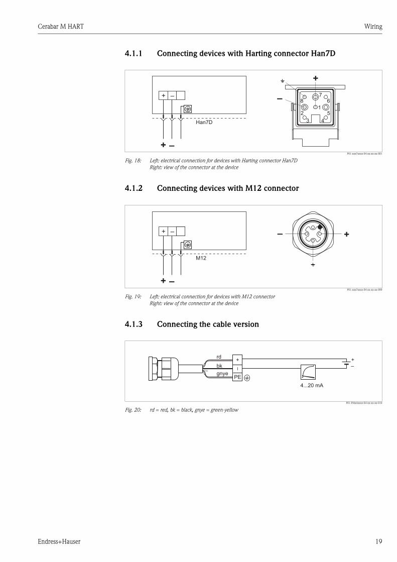
4.1.1 Connecting devices with Harting connector Han7D
P01-xxx7xxxx-04-xx-xx-xx-001
Fig. 18: Left: electrical connection for devices with Harting connector Han7D
Right: view of the connector at the device
4.1.2 Connecting devices with M12 connector
P01-xxx7xxxx-04-xx-xx-xx-000
Fig. 19: Left: electrical connection for devices with M12 connector
Right: view of the connector at the device
4.1.3 Connecting the cable version
P01-PMx4xxxx-04-xx-xx-xx-010
Fig. 20: rd = red, bk = black, gnye = green-yellow
Han7D
–+
+ – –
+
15
4
67
8
2
3
M12
–+
+ – – +
–
++
PE
–
rd
bk
gnye
4...20 mA
Wiring Cerabar M HART
20 Endress+Hauser
4.1.4 Connecting the valve connector M16, ISO4400
P01-xMx5xxxx-04-xx-xx-xx-005
Fig. 21: Left: electrical connection for devices with a valve connector
Right: view of the connector at the device
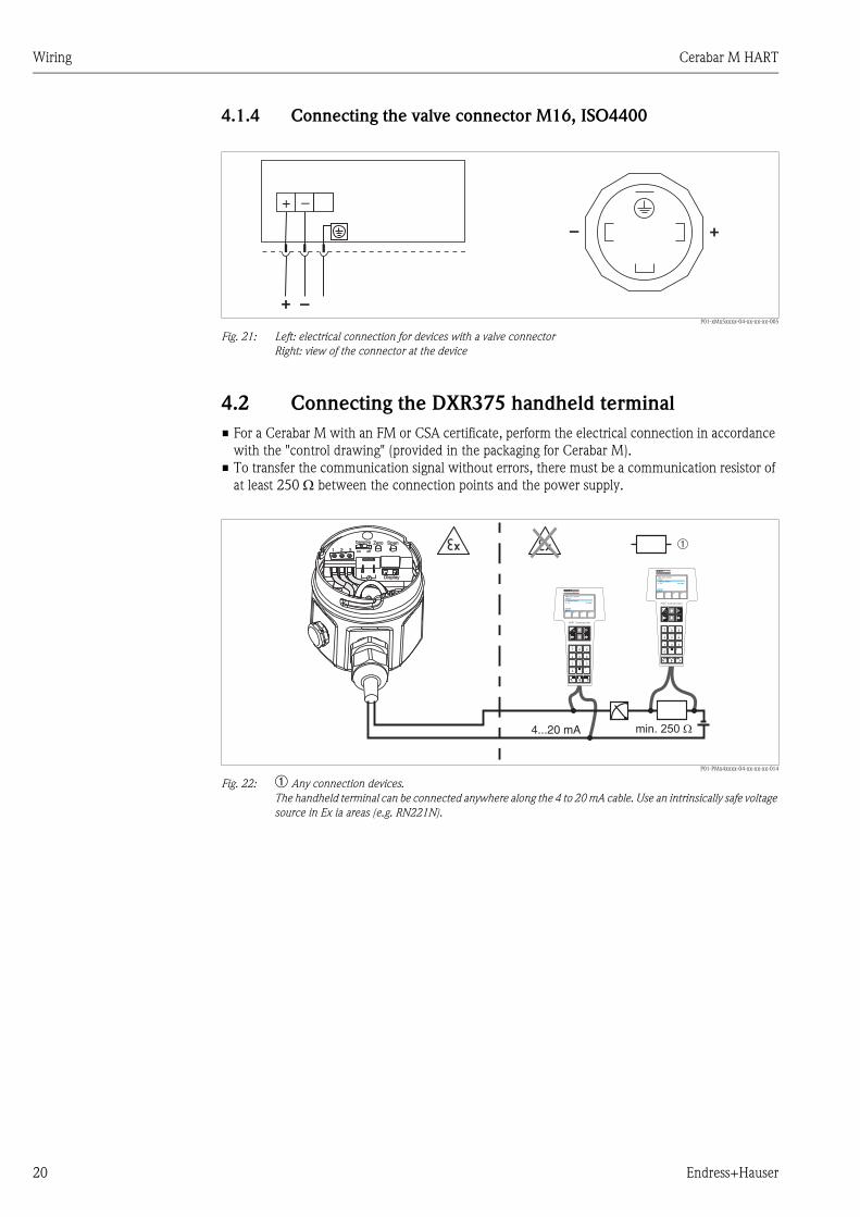
4.2 Connecting the DXR375 handheld terminal
• For a Cerabar M with an FM or CSA certificate, perform the electrical connection in accordance
with the "control drawing" (provided in the packaging for Cerabar M).
• To transfer the communication signal without errors, there must be a communication resistor of
at least 250 between the connection points and the power supply.
P01-PMx4xxxx-04-xx-xx-xx-014
Fig. 22: ➀ Any connection devices.
The handheld terminal can be connected anywhere along the 4 to 20 mA cable. Use an intrinsically safe voltage
source in Ex ia areas (e.g. RN221N).
–+
+ –
+–
4...20 mA min. 250 �
IO
FMD 230:LIC0001Online1 >Group Select2 PV 20 mbar
HELP IO
FMD 230:LIC0001Online1 >Group Select2 PV 20 mbar
HELP
1 2
+ –
3
ZeroDamping
on off
Span
Display
➀

Cerabar M HART Wiring
Endress+Hauser 21
4.3 Connecting Commubox FXA191/FXA195
P01-PMx4xxxx-04-xx-xx-xx-015
Fig. 23: ➀ Personal computer with Endress+Hauser operating program. ➁ Minimum total resistance 250 .
The Commubox can be connected anywhere along the 4 to 20 mA cable.
4.3.1 Connecting Commubox FXA191
The Commubox FXA191 connects intrinsically safe transmitters to a computer's serial interface
(RS 232C) using the HART protocol. This allows remote operation of the measuring transmitter
using Endress+Hauser operating programs. The Commubox is supplied with power through the
serial interface. The Commubox is also suitable for connection to intrinsically safe circuits. See
Technical Information TI404F for further information.
4.3.2 Connecting Commubox FXA195
The Commubox FXA195 connects intrinsically safe transmitters to a computer's USB port using the
HART protocol. This allows remote operation of the measuring transmitter using Endress+Hauser
operating programs. The Commubox is supplied with power through the USB port. The Commubox
is also suitable for connection to intrinsically safe circuits. See Technical Information TI237F for
further information
4.4 Connecting the measuring unit
4.4.1 Supply voltage
! Note!
• When using the measuring device in hazardous areas, installation must comply with the
corresponding national standards and regulations and the Safety Instructions or Installation or
Control Drawings.
• All explosion protection data are given in separate documentation which is available upon
request. The Ex documentation is supplied as standard with all devices approved for use in
hazardous areas.
Supply voltage
• For non-hazardous areas: 11.5 to 45 V DC
4.4.2 Cable specification
• Endress+Hauser recommends using twisted, shielded two-wire cables.
• Terminals for wire cross-sections: 0.14 to 2.5 mm2
• Cable outer diameter: 5 to 9 mm
1 2
+ –
3
ZeroDamping
on off
Span
Display
4…20 mA
➀
➁CommuboxFXA191/FXA195

Wiring Cerabar M HART
22 Endress+Hauser
4.4.3 Load
P01-PMx4xxxx-05-xx-xx-xx-000
Fig. 24: Load diagram, observe explosion protection.
➀ Power supply 11.5 to 45 V DC for devices for non-hazardous areas, 1/3 D, EEx d, EEx nA, FM XP, FM DIP, CSA XP
and CSA Dust-Ex
➁ Power supply 11.5 to 30 V DC for EEx ia, 1 D, 1/2 D 1/2G, FM IS and CSA IS
RLmax Maximum load resistance
U Supply voltage
! Note!
When operating via a handheld terminal or PC with an operating program, a minimum
communication resistance of 250 must be taken into account.
4.4.4 Shielding/potential matching
• You achieve optimum shielding against interference influences if the shielding is connected on
both sides (in the cabinet and at the device). If potential equalization currents are expected in the
plant, only ground the shielding on one side, preferably at the transmitter.
• When using in hazardous areas, you must observe the applicable regulations.
Separate Ex documentation with additional technical data and instructions is included with all
Ex devices as standard.
4.5 Potential equalization
Ex applications: Connect all devices to the local potential equalization system.
Observe the applicable regulations.
4.6 Post-connection check
Perform the following checks after completing electrical installation of the device:
• Does the supply voltage match the specifications on the nameplate?
• Is the device connected as per Section 4.1?
• Are all the screws firmly tightened?
• Are the housing covers screwed down tight?
The connected onsite display lights up as soon as voltage is applied to the device.
0
1522
1295
840
386
11.5 30 4520 U[V]
U – 11.5 VRLmax 22 mA
≤
[ ]ΩRLmax
➀
➁
40

Cerabar M HART Operation
Endress+Hauser 23
5 Operation
5.1 Onsite display (optional)
A plug-in onsite display is used as the display unit. The display can be rotated in 90° stages.
P01-PMx4xxxx-07-xx-xx-xx-004
Fig. 25: Onsite display
➀ 4-digit display of measured values and input parameters
➁ Bar graph, display of current measured value
➂ Nominal measuring range
5.1.1 Function of the onsite display
The onsite display has two display modes:
• Display in measurement mode: This is shown as standard.
• Display in calibration mode: This is shown after pressing the Zero or Span key once. It returns
automatically to measurement mode display after 2 seconds.
The bar graph displays the current value (4 to 20 mA) belonging to the pressure value.
P01-PMx4xxxx-07-xx-xx-xx-001
Fig. 26: Function of the onsite display
A Display in measuring mode
B Display in calibration mode
➀ Lower-range value
➁ Upper-range value
➂ Set measuring range in measuring limits
➃ Display of calibration point (Z (Zero) = lower-range value (LRV) or S (Span) = upper-range value (URV))
0…1 bar
0.753
➀
➁
➂
0…1 bar
0.753
0.753
0.250Z
S
A:
B:
➀
➂
➁
➃

Operation Cerabar M HART
24 Endress+Hauser
5.2 Operating elements
5.2.1 Position of the operating elements on the electronic insert
The onsite display is supplied ready-mounted if it is ordered with the device. In such instances, the
onsite display with the retaining ring must be released from the electronic insert before operating.
Removing the display:
• Push up the latch with the arrow until the grip of the retaining ring on the electronic insert is
audibly released.
• Release the retaining ring and lift off carefully to prevent damage to the display cables.
• During operation, you can fit the display onto the edge of the housing.
P01-PMx4xxxx-19-xx-xx-xx-025
Fig. 27: Position of operating elements
➀ Switch for damping on/off
➁ Key for calibrating the lower-range value (Zero = Lower-range value (LRV))
➂ Key for calibrating the upper-range value (Span = Upper-range value (URV))
➃ Terminal lugs for measuring the signal current
5.2.2 Function of the operating elements
Use the "Zero" and "Span" keys to set the lower-range value and upper-range value of the bar graph
in the display module. These settings do not have any effect on the digital output value (OUT value)
and the "measured value" in the matrix field V0H0.
+
+
–
–
ZeroDamping
on off
Span
Display
➁➀ ➁3
4
No. Operating element Function
➀ Damping switch Switch position "off": damping 0 s
Switch position "on": damping 2 s
It is possible to enter a damping value between 0 and 40 s via communication,
e.g. with the handheld terminal.
➁ Key for lower-range value The value currently saved for the lower-range value, e.g. 4 mA (zero point), is
displayed and the pressure present is accepted as the lower-range value.
➂ Key for upper-range value The value currently saved for the upper-range value, e.g. 20 mA, is displayed
and the pressure present is accepted as the upper-range value.
➁ + ➂ Bias key combination:
Key for lower-range value and
Key for upper-range value
The value currently saved for the bias pressure is displayed and the pressure
present is accepted as the bias pressure.
➁ + ➂ Reset key combination:
Key for lower-range value and
Key for upper-range value
The reset is triggered if the two keys are pressed and held for at least
7 seconds.

Cerabar M HART Operation
Endress+Hauser 25
If the display does not show zero after calibrating the lower-range value at zero operating pressure
(position-dependent), it can be corrected to zero by adopting a bias pressure.
5.3 Operation via Endress+Hauser operating program
5.3.1 FieldCare
FieldCare is an Endress+Hauser asset management tool based on FDT technology. With FieldCare,
you can configure all Endress+Hauser devices as well as devices from other manufacturers that
support the FDT standard.
FieldCare supports the following functions:
• Configuration of transmitters in online operation
• Loading and saving device data (upload/download)
• Documentation of the measuring point
Connection options:
• HART via Commubox FXA195 and the USB interface of a computer
! Note!
• See also Page 21, Section 4.3.2 "Connecting Commubox FXA195".
• For more information, see www.endress.com.
5.3.2 Commuwin II
With the Commuwin II display and operating program, Cerabar M can be configured and operated
as follows:
• Via matrix operation or
• Via graphic operation
For this, the corresponding server (e.g. HART or ZA672) must be activated. For a description of the
Commuwin II operating program, see Operating Instructions BA124F.
Matrix operation (Device parameter menu)
You can access the extended functions of the
Cerabar M using the "Device parameter/matrix
operation" menu.
• Each row is assigned to a function group.
• Every field represents a parameter.
• The setting parameters are entered in the
appropriate fields and confirmed with .
P01-PMx4xxxx-20-xx-xx-en-001

Operation Cerabar M HART
26 Endress+Hauser
Graphic operation
5.4 Operation via Universal HART Communicator DXR375
When operating via the HART protocol, a menu operation system derived from the matrix is used
(see also Operating Instructions for the handheld terminal).
• The "Select group" menu calls up the matrix.
• The menu headers are displayed on the individual rows.
• The parameters are set via sub-menus.
P01-PMx4xxxx-19-xx-xx-en-028
Fig. 28: Left: Menu operation with the DXR375; right: Universal HART Communicator DXR375 handheld terminal
The electrical connection of the Universal HART Communicator DXR375 handheld terminal is
described in Section 4.2, and the step-by-step commissioning of the measuring point in Section 6.
Commuwin II offers graphic templates for
certain configuration procedures which you can
access via the "Device parameter/graphic
operation" menu. The parameter changes are
entered directly here and confirmed with .
P01-PMx4xxxx-20-xx-xx-en-002
IO
PMC 41:LIC0001Online1 >Group Select2 PV 20 mbar
HELP
F1 F4F2 F3
PMC 41: LIC0001Online
2 PV 20 mbar1->Wähle Gruppe
HELP
F1 F4F2 F3
PMC 41: LIC0001Wähle Gruppe
2 Transmitter Information3 Sensordaten4 Service5 Kommunikaton
1->Grundabgleich
HOME
F1 F4F2 F3
PMC 41: LIC0001Wähle Gruppe
3 Setze 20 mA4 Bestätige 4 mA
autom.
1->Meßwert2 Setze 4 mA
HOME

Cerabar M HART Commissioning
Endress+Hauser 27
6 Commissioning
6.1 Function check
Carry out a post-installation and a post-connection check as per the checklist before commissioning
the device.
• "Post-installation check" checklist (see Page 17, Section 3.4 "Post-installation check")
• "Post-connection check" checklist (see Page 22, Section 4.6 "Post-connection check")
6.2 Onsite commissioning
6.2.1 Preparatory work
• Connect Cerabar M to the power supply (Section 4.1 "Connecting the device").
• Ensure that a pressure can be specified within the required measuring range.
• If you have not installed an onsite display, connect a multimeter
(4 to 20 mA) to the terminal lugs provided for this purpose.
• If you have installed an onsite display, the calibration values appear there.
6.2.2 Configuring the damping
The damping affects the speed at which the output signal and the onsite display react to changes
in pressure. The DIP switch for setting the damping is located on the electronic insert.
• Switch position off: damping 0 s
• Switch position on: damping 2 s
P01-PMx4xxxx-19-xx-xx-xx-029
Fig. 29: ➀ Damping switch. ➁ Key for lower-range value. ➂ Key for upper-range value.
1 2 3
ZeroDamping
on off
Span
➀
1 2 3
ZeroDamping
on off
Span
➁ ➂

Commissioning Cerabar M HART
28 Endress+Hauser
6.2.3 Lower-range value calibration
Use the "Zero" key to query the lower-range value currently saved or to calibrate the lower-range value.
6.2.4 Upper-range value calibration
The upper-range value is calibrated using the "Span" key:
1. Specify the exact pressure for the upper-range value.
2. Press the "Span" key. The calibration value currently saved appears on the optional onsite
display.
3. Release the key and press the key a second time within 2 seconds. Hold down the key for 3 to
4 seconds until the "S" symbol stops flashing. The pressure present is now adopted for the new
upper-range value.
6.2.5 Position adjustment - only display (bias pressure)
If the display does not show zero after calibrating the lower-range value at zero operating pressure
(position-dependent), it can be corrected to zero by adopting the available bias pressure (position
adjustment).
• To query the lower-range value:
Press the "Zero" key. The current calibration
value appears on the optional onsite display
and remains on the display for another
2 seconds approximately once the key is
released.
• To calibrate the lower-range value:
1. Specify the exact pressure for the lower-
range value (zero point).
2. Press the "Zero" key. The calibration value
currently saved appears on the optional
onsite display.
3. Release the key and press the key a second
time within approx. 2 seconds. Hold down
the key for 3 to 4 seconds until the "Z"
symbol stops flashing. The pressure
present is now adopted as the new lower-
range value.
P01-PMx4xxxx-19-xx-xx-xx-030
Fig. 30: Optional onsite display: the "S" and "Z" symbol
on the left
0,250Z
S
• The bias pressure is calibrated
via the Zero and Span keys:
1. Press the Zero and Span keys
simultaneously. The bias pressure
currently saved appears on the optional
onsite display.
2. Release the keys and press the keys a
second time within 2 seconds. Hold down
the keys until the "Z" and "S" symbol stop
flashing. The pressure present is now
adopted as the new bias pressure.
" Caution!
Do not hold Zero and Span down for longer than
6 seconds, otherwise the system is reset – see
next section.P01-PMx4xxxx-19-xx-xx-xx-030
Fig. 31: Optional onsite display: the "S" and "Z" symbol
on the left
p
pB
ias
p+pBias
pe=0

Cerabar M HART Commissioning
Endress+Hauser 29
6.2.6 Reset to factory setting (reset)
The upper-range value is calibrated using the "Span" key:
Use the Zero and Span keys to reset to the factory setting:
• To the lower-range value (Zero) = lower sensor measuring limit
• To the upper-range value (Span) = upper sensor measuring limit
• The bias pressure to zero = 0.0 pressure unit
1. Press the Zero and Span keys simultaneously.
2. Release the keys, press them a second time within 2 seconds and hold them for at least
7 seconds. Any reset that has taken place is confirmed on the optional onsite display with
"Res".
6.3 Commissioning via communication
6.3.1 Preparatory work
• Connect Cerabar M to the power supply (Section 4.1 "Connecting the device").
• Decide which tool you want to use to operate the Cerabar M and establish the connection
(Operating program see Section 5.3, Universal HART Communicator DXR375 see Section 4.2).
6.3.2 Reset to factory setting (reset)
By entering a certain code, the matrix entries can be reset partially or completely to the factory
settings. Further information on the various types of reset and their effects is given in Section 8.5
"Reset".
Main group: Transmitter information
# Matrix (VH position) Path through the menus Entry
1 Reset to factory setting (reset)
V2H9 ➤ Default Values e.g. 2380
Enter

Commissioning Cerabar M HART
30 Endress+Hauser
6.3.3 Configuring the damping
The damping affects the speed at which the output signal and the onsite display damping react to
changes in pressure. To set the damping using the handheld terminal, the damping switch on the
electronic insert must be set to "on". With the handheld terminal, values between 0 and 40 seconds
can be then selected for the damping.
P01-PMx4xxxx-19-xx-xx-xx-032
Fig. 32: ➀ Damping switch. ➁ Jump in pressure. ➂ Output signal.
6.3.4 Selecting a pressure unit
By selecting the pressure unit you define in which unit the pressure-specific "Select pressure unit"
parameters are displayed. The pressure units in the table below can be selected. After selecting
a new pressure unit, all entries for pressure are converted to the new unit
e.g. 0 to 1 bar = 0 to 14.5 psi.
Main group: Basic calibration
# Matrix (VH position) Path through the menus Entry
1 Set the damping switch to "on"
2 Suppress fluctuations in the measured value
V0H7 ➤ Output damping = 0 to 40 s
e.g. 20 s
Enter
1 2 3
ZeroDamping
on off
Span
➀I
0 � 2� 3�
63 %
100 %➁
➂
Main group: Basic calibration
# Matrix (VH position) Path through the menus Entry
1 Select pressure unit
V0H7 ➤Select pressure unit e.g. psi
Enter
Unit Unit Unit Unit Unit
mbar kPa in H2O kg / cm2 Torr
bar MPa ft H2O kgf / cm2 mm Hg
Pa mm H2O psi atm in Hg
hPa m H2O g / cm2 lb / ft2

Cerabar M HART Commissioning
Endress+Hauser 31
6.3.5 Lower-range and upper-range value: setting without reference
pressure
The desired pressure for the lower-range value (zero point) and the upper-range value is set using
the handheld terminal without specifying a reference pressure.
6.3.6 Lower-range and upper-range value: setting with reference
pressure
A reference pressure is available which corresponds exactly to the desired lower-range value (zero
point) and the desired upper-range value.
Main group: Basic calibration
# Matrix (VH position) Path through the menus Entry
1 Enter known pressure for the lower-range value
P01-PMx4xxxx-19-xx-xx-xx-033
Fig. 33: ➀ No reference pressure
V0H1 ➤ Set 4 mA e.g. 0 psi
Enter
2 Enter known pressure for the upper-range value
V0H2 ➤ Set 20 mA e.g. 14.5 psi
Enter
Main group: Basic calibration
# Matrix (VH position) Path through the menus Entry
1 Accept pressure present for the lower-range value
P01-PMx4xxxx-19-xx-xx-xx-034
Fig. 34: ➀ Reference pressure
V0H3 ➤ Confirm 4 mA
automatically
e.g. 0 psi
Enter
2 Accept pressure present for the upper-range value
V0H4 ➤ Confirm 20 mA
automatically
e.g. 14.5 psi
Enter
➀
➀

Commissioning Cerabar M HART
32 Endress+Hauser
6.3.7 Position adjustment - only display (bias pressure)
If the display does not show zero after calibrating the zero point at zero operating pressure (position-
dependent), the display value can be corrected to zero by entering or adopting a bias pressure
(position adjustment).
6.3.8 4 mA threshold (current output min. 4 mA)
The signal current in interference-free operation is set to 3.8 to 20.5 mA as standard. Selecting the
4 mA threshold guarantees that a minimum signal current of 4 mA is not undershot.
6.3.9 Safety alarm
To signal an error, an error code is transmitted with the measured value. Safety alarm: The bar graph
on the onsite display also assumes the value you have selected. The following values can be selected:
• MIN: 3.6 mA
• MAX: 22 mA
• CONTINUE: continue measuring
Main group: Basic calibration
# Matrix (VH
position)
Path through the
menus
Entry
P01-PMx4xxxx-19-xx-xx-xx-031
1 Set display to zero by entering a known bias pressure
(position-dependent pressure).
V0H5 ➤ Set bias pressure e.g. 5 psi
Enter
Alternatively
2 Set display to zero. A bias pressure present (position-
dependent pressure) is accepted as zero pressure.
V0H6 ➤ Confirm
bias pressure
automatically
Enter
Main group: Sensor data
# Matrix (VH position) Path through the menus Entry
1 Select pressure unit
V7H3 ➤ Off current output
min. 4 mA
e.g. On
Enter
Main group: Basic calibration
# Matrix
(VH position)
Path through the
menus
Entry
P01-PMx4xxxx-19-xx-xx-xx-035
Fig. 35: ➀ continue measurement
1 Select safety alarm
V0H8 ➤ Select safety e.g. MAX.
Enter
p
pB
ias
p+pBias
pe=0
t
I
➀

Cerabar M HART Commissioning
Endress+Hauser 33
6.4 Locking/unlocking operation
After calibration or after entering all the parameters, operation can be locked using a three-digit code
number other than 130. This locks all the fields and functions except V9H9 "Security locking".
Entering 130 deactivates the locking.
6.5 Information on the measuring point
The following information on the measuring point can be called up with the handheld terminal or
using the operating program:
Main group: Service
# Matrix (VH position) Path through the menus Entry
1 Locking operation
V9H9 ➤ Security locking e.g. 131
Enter
2 Disable locking
V9H9 ➤ Security locking 130
Enter
Matrix field Display or entry
Measured values
V0H0 Pressure primary value
V7H0 Current display: present current in mA
V7H8 Sensor pressure (unit in V0H9) can be selected
V9H7 Current damped pressure without bias correction
Sensor data
V7H4 Lower calibration pressure
V7H5 Upper calibration pressure
V7H6 Low sensor limit (unit can be selected in V0H9)
V7H7 High sensor limit (unit can be selected in V0H9)
Information on the transmitter
V2H2 8011/8012 = software number
V2H7 Sensor data number:
Number of the entry in the sensor table (1 to 10), please take from sensor pass
V2H8 Sensor data value:
Entry in sensor table, contains all sensor-specific data. Please take from sensor pass.
Error response mode
V2H0 Current diagnostic code
V2H1 Last diagnostic code

Maintenance Cerabar M HART
34 Endress+Hauser
6.5.1 Communication layer
7 Maintenance
Keep the pressure compensation and GORE-TEX® filter ➀ free from dirt.
P01-PMx4xxxx-17-xx-xx-xx-001
7.1 Exterior cleaning
Please note the following points when cleaning the device:
• The cleaning agents used should not corrode the surface and the seals.
• Mechanical damage to the diaphragm, e.g. due to pointed objects, must be avoided.
• Observe the degree of protection of the device. See Page 6, Section 2.1.1 "Nameplates".
8 Troubleshooting
8.1 Fault
If the Cerabar M detects an error, the following occurs:
• An error code is generated and flashes on the onsite display
• When the onsite display is connected, the bar graph accepts the selected value for the error
message (MIN, MAX, CONTINUE)
• The display value and the bar graph flash
• Error codes can be read in the "Transmitter information" main group or in matrix fields V2H0 and
V2H1
Matrix field Display
VAH0 Name of the measuring point.
Here you can name the measuring point using max. 8 characters.
VAH1 System identification (descriptor)
Here you can enter max. 16 characters.
VAH2 User text
Here you can enter max. 8 characters.
VAH3 Device serial number
VAH4 Sensor serial number
➀

Cerabar M HART Troubleshooting
Endress+Hauser 35
8.2 Warning
If the Cerabar M detects a warning, the following occurs:
• An error code is generated: Cerabar M continues to measure
• The scale flashes when the onsite display is connected
• Error codes can be read in the "Transmitter information" main group or in matrix fields V2H0 and
V2H1
8.3 Error codes in V2H0 and V2H1
Code Type Cause and remedial action Priority
E101 Fault Sensor table checksum error
• Appears when the sensor data are being entered.
The error message disappears when the sensor data are entered completely
and correctly.
• Checksum is incorrect
Check sensor data - see "Sensor data no." (V2H7) and "Sensor data value"
(V2H8) parameters.
2
E103 Fault Initialization active
• The electronics are initialized after connecting the device.
Wait for the initialization process to complete
1
E104 Warning Sensor calibration
• The values in V7H4 and V7H5 (Low sensor cal and High sensor cal) are too
close to one another, e.g. following sensor recalibration
• Perform a reset (code 2380) and recalibrate the sensor
8
E106 Fault Upload/download active
• Wait for download to complete.
5
E115 Fault Sensor overpressure
• Overpressure present. Reduce pressure until message disappears.
• Cable connection sensor – electronic insert disconnected.
Check cable connection.
• Sensor defective. Replace sensor
3
E116 Fault Download error (PC-transmitter)
• During the download, the data are not correctly transmitted to the processor,
e.g. because of open cable connections, spikes (ripple) on the supply voltage
or EMC effects. Check cable connection PC – transmitter. Perform "5140"
reset. Start download again.
6
E120 Fault Sensor low pressure
• Pressure too low. Increase pressure until message disappears.
• Cable connection sensor – electronic insert disconnected.
Check cable connection.
• Sensor defective. Replace sensor.
4
E613 Warning Current simulation active
• Remains until the simulation is complete – see also Section 8.4.
7
E620 Warning Measured value outside lower-range value/upper-range value 9

Troubleshooting Cerabar M HART
36 Endress+Hauser
8.4 Current simulation
If the function or certain reactions of connected switching units need to be checked, a signal current
can be simulated independently of the operating pressure present.
8.5 Reset
8.5.1 Reset via onsite operation
Use the Zero and Span keys to reset to the factory setting:
• To the lower-range value (Zero) = lower sensor measuring limit
• To the upper-range value (Span) = upper sensor measuring limit
• The bias pressure to zero = 0.0 pressure unit
1. Press the Zero and Span keys simultaneously.
2. Release the keys, press them a second time within 2 seconds andhold them for at least
7 seconds. Any reset that has taken place is confirmed on the onsite display (optional) with
"Res".
8.5.2 Reset via communication
By entering a certain code, the matrix field entries can be reset partially or completely to the factory
settings.
The Cerabar M makes a distinction between four different reset code numbers with different effects.
See the following table to find out which parameters are reset by reset code numbers 5140, 2380,
2509 or 731.
Main group: Additional functions
# Matrix (VH position) Path through the menus Entry
1 V7H1 ➤ Simulation ON
2 V7H2 ➤ Simulate current e.g. 22 mA
Main group: Additional functions
# Matrix (VH position) Path through the menus Entry
1 V2H9 ➤ Reset e.g. 2380

Cerabar M HART Troubleshooting
Endress+Hauser 37
Table of parameters that can be reset by the reset code numbers.
8.6 Repair
The Endress+Hauser repair concept provides for measuring devices to have a modular design and
that the customer may also carry out repairs.
The "Spare parts" section contains all the spare parts, and their order numbers, which you can order
from Endress+Hauser to repair the Cerabar M. Where necessary, the spare parts also include
replacement instructions.
! Note!
• For certified devices, please refer to the "Repair of Ex-certified devices" section.
• For more information on service and spare parts contact Endress+Hauser Service.
See www.endress.com/worldwide.
• Only the process connection on the PMC41 can be
exchanged by the customer. For all other models, a device without a display and housing can be
ordered. See Technical Information TI399P, "Ordering information" section.
H0 H1 H2 H3 H4 H5 H6 H7 H8 H9
V0
5140
2380
2509
731
Measured
value
Set
4 mA
= V7H6
= V7H6
= V7H6
Set
20 mA
= V7H7
= V7H7
= V7H7
4 mA
automat.
deleted
deleted
deleted
20 mA
automat.
deleted
deleted
deleted
Set
bias pres-
sure
0.0
0.0
0.0
Bias pres-
sure
automat.
deleted
deleted
deleted
Output
damping
0.0
0.0
0.0
Select
safety
max.
max.
max.
Pressure
unit
bar
V2
5140
2380
2509
731
Diagnostic
code
Last
diag. code
0
0
Software
no.
V3 to V6
V7
5140
2380
2509
731
Current
display
Simulation
Off
Simulate
current
deleted
Current
min. 4 mA
Off
Off
Off
Low Sen.
Calibration
= V7H6
= V7H6
High Sen.
Calibration
= V7H7
= V7H7
Lower
Measuring
Limit
Upper
Measuring
Limit
Sensor
Pressure
V8
V9
5140
2380
2509
731
Pressure
before
bias corr.
Security
locking
130
VA
5140
2380
2509
731
Measuring
point
deleted
deleted
System ID
deleted
deleted
User text
deleted
Serial
number
Serial No.
Sensor

Troubleshooting Cerabar M HART
38 Endress+Hauser
8.7 Repair of Ex-certified devices
# Warning!
When repairing Ex-certified devices, please note the following:
• Only specialist personnel or Endress+Hauser may undertake repairs to certified devices.
• Relevant standards, national hazardous area regulations and safety instructions and certificates
must be observed.
• Only use genuine spare parts from Endress+Hauser.
• When ordering spare parts, please check the device designation on the nameplate. Identical parts
may only be used as replacements.
• Electronic inserts or sensors already in use in a standard device may not be used as spare parts for
a certified device.
• Carry out repairs according to the instructions. After a repair, the device must fulfill the
requirements of the specified individual tests.
• A certified device may only be converted to another certified version by Endress+Hauser.
• All repairs and modifications must be documented.

Cerabar M HART Troubleshooting
Endress+Hauser 39
8.8 Spare Parts
An overview of the spare parts for your device is available in the internet at www.endress.com.
To obtain information on the spare parts, proceed as follows:
1. Go to "www.endress.com" and select your country.
2. Click "Instruments".
3. Enter the product name into the "product name" field.
4. Select the device.
5. Click the "Accessories/Spare parts" tab.
6. Select the required spare parts (You may also use the overview drawing on the right side of the
screen.)
When ordering spare parts, always quote the serial number indicated on the nameplate. As far as
necessary, the spare parts also include replacement instructions.

Technical data Cerabar M HART
40 Endress+Hauser
8.9 Return
Before you send in a device for repair or inspection, perform the following:
• Remove all traces of the fluid. Pay special attention to the grooves for seals and crevices which
could contain fluid residues. This is especially important if the fluid is hazardous to health. Please
refer also to the "Declaration of Hazardous Material and Decontamination".
Please enclose the following when returning the device:
• The duly completed and signed "Declaration of Hazardous Material and Decontamination".
Only then can Endress+Hauser inspect or repair the returned device.
• The chemical and physical properties of the fluid.
• A description of the application.
• A description of the error which occurred.
• Special instructions on handling, if necessary, e.g. safety data sheet as per EN 91/155/EEC.
8.10 Disposal
When disposing, separate and recycle the device components based on the materials.
8.11 Software history
9 Technical data
For technical data, please refer to the Technical Information TI399P for Cerabar M.
Date Software version Changes to software Operating Instructions
04.1999 1.0 Original software.
Compatible with:
– Commuwin II
– HART Communicator 375
– FieldCare
– AMS
– PDM
BA201P/00/EN/05.99
52002513
02.2001/
02.2002
1.1/1.2 Reset onsite of Upper-range value, Lower-
range value, bias pressure/Adjusted for OEM
manufacturers
BA201P/00/EN/04.02
52013871
BA201P/00/EN/11.03
52013871
BA201P/00/EN/12.03
52022183
BA201P/00/EN/06.08
71064502
BA201P/00/EN/04.10
71113268

Cerabar M HART Operating matrix
Endress+Hauser 41
10 Operating matrix
The following matrix gives an overview of the factory settings.
You can also enter your values here.
H0 H1 H2 H3 H4 H5 H6 H7 H8 H9
V0 Basic
calibration
Measured
value
Set
4 mA
Set
20 mA
Confirm
4 mA
automat.
Confirm
20 mA
automat.
Set
bias pressure
Confirm bias
pressure
automat.
Set output
damping 0
to 40 s
Select
safety
MIN.
MAX.
CONTINUE
Select
pressure
unit
V1
V2
Trans-
mitter
information
Diagnostic
code
Last
diagnostic
8011/8012
Software
No.
Sensor data
No.
Sensor data
value
Reset
V3 to V6
V7
Sensor data
Current
display
Off
Simulation
Simulate
current
Off
Current
output
min. 4 mA
Low
sensor
calibration
High
sensor
calibration
Lower
measuring
limit
Upper
measuring
limit
Sensor
pressure
V8
V9
Service
Pressure
before bias
correction
Security
locking:
130
Unlocking
device: 130
Release
V2H7,
V2H8: 333
VA
Communi-
cation
Measuring
point
System
identificatio
n
User text Serial
number
Serial
number
sensor
= display field
H0 H1 H2 H3 H4 H5 H6 H7 H8 H9
V0 — 0.0 V7H7 — — 0.0 — 0.0 MAX. bar
V1
V2 0 xxxx 0
V3 to V6
V7 — OFF — OFF — — — 0
V8
V9 — 130
VA ————— ————

Cerabar M HART Index
42 Endress+Hauser
Index
AAlarm messages . . . . . . . . . . . . . . . . . . . . . . . . . . . . . . . . 35
CCable specification . . . . . . . . . . . . . . . . . . . . . . . . . . . . . . 21
Commubox FXA191, connection . . . . . . . . . . . . . . . . . . . 21
Commubox FXA195, connection . . . . . . . . . . . . . . . . . . . 21
DDiaphragm seals, installation instructions . . . . . . . . . . . . . 13
Diaphragm seals, vacuum application . . . . . . . . . . . . . . . . 14
Display. . . . . . . . . . . . . . . . . . . . . . . . . . . . . . . . . . . . . . . 23
EElectrical connection . . . . . . . . . . . . . . . . . . . . . . . . . . . . 18
Error messages . . . . . . . . . . . . . . . . . . . . . . . . . . . . . . . . . 35
FFieldCare . . . . . . . . . . . . . . . . . . . . . . . . . . . . . . . . . . . . . 25
HHazardous areas . . . . . . . . . . . . . . . . . . . . . . . . . . . . . . . . . 4
IIncoming acceptance . . . . . . . . . . . . . . . . . . . . . . . . . . . . . 9
Installation instructions for devices with diaphragm seals. . 13
Installation instructions for devices without diaphragm seals . .
10
LLoad . . . . . . . . . . . . . . . . . . . . . . . . . . . . . . . . . . . . . . . . 22
Locking operation. . . . . . . . . . . . . . . . . . . . . . . . . . . . . . . 33
MMeasuring arrangement for level measurement . . . . . . . . . 12
Measuring arrangement for pressure measurement . . . . . . 11
NNameplate . . . . . . . . . . . . . . . . . . . . . . . . . . . . . . . . . . . . . 6
OOnsite display. . . . . . . . . . . . . . . . . . . . . . . . . . . . . . . . . . 23
PPipe mounting . . . . . . . . . . . . . . . . . . . . . . . . . . . . . . . . . 16
Position adjustment . . . . . . . . . . . . . . . . . . . . . . . . . . 27, 29
Potential equalization . . . . . . . . . . . . . . . . . . . . . . . . . . . . 22
RRepair . . . . . . . . . . . . . . . . . . . . . . . . . . . . . . . . . . . . . . . 37
Repair of Ex-certified devices . . . . . . . . . . . . . . . . . . . . . . 38
Reset-Code . . . . . . . . . . . . . . . . . . . . . . . . . . . . . . . . . . . 36
SScope of delivery . . . . . . . . . . . . . . . . . . . . . . . . . . . . . . . . 8
Shielding . . . . . . . . . . . . . . . . . . . . . . . . . . . . . . . . . . . . . 22
Software history . . . . . . . . . . . . . . . . . . . . . . . . . . . . . . . . 40
Spare Parts . . . . . . . . . . . . . . . . . . . . . . . . . . . . . . . . . . . . 39
Storage . . . . . . . . . . . . . . . . . . . . . . . . . . . . . . . . . . . . . . . . 9
Supply voltage . . . . . . . . . . . . . . . . . . . . . . . . . . . . . . . . . 21
TTemperature isolator, installation instructions . . . . . . . 14–15
Troubleshooting . . . . . . . . . . . . . . . . . . . . . . . . . . . . . . . . 35
UUnlocking operation . . . . . . . . . . . . . . . . . . . . . . . . . . . . . 33
WWall mounting . . . . . . . . . . . . . . . . . . . . . . . . . . . . . . . . . 16
Warnings . . . . . . . . . . . . . . . . . . . . . . . . . . . . . . . . . . . . . 35

P/S
F/K
onta
XIV
Because of legal regulations and for the safety of our employees and operating equipment, we need the "Declaration of Hazardous Materialand De-Contamination", with your signature, before your order can be handled. Please make absolutely sure to attach it to the outside of thepackaging.Aufgrund der gesetzlichen Vorschriften und zum Schutz unserer Mitarbeiter und Betriebseinrichtungen, benötigen wir die unterschriebene"Erklärung zur Kontamination und Reinigung", bevor Ihr Auftrag bearbeitet werden kann. Bringen Sie diese unbedingt außen an derVerpackung an.
Serial number
Seriennummer ________________________Type of instrument / sensor
Geräte-/Sensortyp ____________________________________________
Process data/Prozessdaten Temperature _____ [°F] [°C]
Conductivity / ________
_____
Leitfähigkeit
/
[μS/cm]
Temperatur Pressure _____ [psi] [ Pa ]
Viscosity _____ [cp] [mm /s]
_____
_____
/
/
Druck
Viskosität2
corrosiveätzend
harmlessunbedenklich
other *sonstiges*
toxicgiftig
Processmedium
IdentificationCAS No.
flammableentzündlich
harmful/irritant
gesundheits-schädlich/
reizend
Medium /concentrationMedium /Konzentration
Returned partcleaned with
Medium forprocess cleaning
Medium and warnings
Warnhinweise zum Medium
* explosive; oxidising; dangerous for the environment; biological risk; radioactive* explosiv; brandfördernd; umweltgefährlich; biogefährlich; radioaktiv
Please tick should one of the above be applicable, include safety data sheet and, if necessary, special handling instructions.Zutreffendes ankreuzen; trifft einer der Warnhinweise zu, Sicherheitsdatenblatt und ggf. spezielle Handhabungsvorschriften beilegen.
Description of failure / Fehlerbeschreibung __________________________________________________________________________
______________________________________________________________________________________________________________
______________________________________________________________________________________________________________
“We hereby certify that this declaration is filled out truthfully and completely to the best of our knowledge.We further certify that the returnedparts have been carefully cleaned. To the best of our knowledge they are free of any residues in dangerous quantities.”“Wir bestätigenw
bestätigen, die vorliegende Erklärung nach unserem besten Wissen wahrheitsgetreu und vollständig ausgefüllt zu haben. Wireiter, dass die zurückgesandten Teile sorgfältig gereinigt wurden und nach unserem besten Wissen frei von Rückständen in gefahrbringen-
der Menge sind.”
(place, date / Ort, Datum)
Company data /Angaben zum Absender
Company / ________________________________
_________________________________________________
Address /
_________________________________________________
_________________________________________________
Firma ___
Adresse
Phone number of contact person /
____________________________________________
Fax / E-Mail ____________________________________________
Your order No. / ____________________________
Telefon-Nr. Ansprechpartner:
Ihre Auftragsnr.
Medium zurEndreinigung
Medium zurProzessreinigung
Medium imProzess
Used as SIL device in a Safety Instrumented System / Einsatz als SIL Gerät in Schutzeinrichtungen
RA No.
Erklärung zur Kontamination und ReinigungDeclaration of Hazardous Material and De-Contamination
Please reference the Return Authorization Number (RA#), obtained from Endress+Hauser, on all paperwork and mark the RA#clearly on the outside of the box. If this procedure is not followed, it may result in the refusal of the package at our facility.
Bitte geben Sie die von E+H mitgeteilte Rücklieferungsnummer (RA#) auf allen Lieferpapieren an und vermerken Sie dieseauch außen auf der Verpackung. Nichtbeachtung dieser Anweisung führt zur Ablehnung ihrer Lieferung.
Name, dept./Abt. (please print / )bitte Druckschrift Signature / Unterschrift

www.endress.com/worldwide
BA201P/00/EN/04.10
71113268
CCS/FM+SGML6.0 71113268