Operating Instructions and Parts Manual 2-Ton...
12
Operating Instructions and Parts Manual 2-Ton Hydraulic Shop Crane Model: JHC-200X WALTER MEIER (Manufacturing) Inc. 427 New Sanford Road LaVergne, Tennessee 37086 Part No. M-106200 Ph.: 800-274-6848 Revision C 09/2012 www.waltermeier.com Copyright © 2012 Walter Meier (Manufacturing) Inc.
Transcript of Operating Instructions and Parts Manual 2-Ton...

Operating Instructions and Parts Manual 2-Ton Hydraulic Shop Crane Model: JHC-200X
WALTER MEIER (Manufacturing) Inc. 427 New Sanford Road LaVergne, Tennessee 37086 Part No. M-106200 Ph.: 800-274-6848 Revision C 09/2012 www.waltermeier.com Copyright © 2012 Walter Meier (Manufacturing) Inc.

2
Warranty and Service Walter Meier (Manufacturing) Inc., warrants every product it sells. If one of our tools needs service or repair, one of our Authorized Service Centers located throughout the United States can give you quick service. In most cases, any of these Walter Meier Authorized Service Centers can authorize warranty repair, assist you in obtaining parts, or perform routine maintenance and major repair on your JET® tools. For the name of an Authorized Service Center in your area call 1-800-274-6848. MORE INFORMATION Walter Meier is consistently adding new products to the line. For complete, up-to-date product information, check with your local Walter Meier distributor, or visit waltermeier.com. WARRANTY JET products carry a limited warranty which varies in duration based upon the product (MW = Metalworking, WW = Woodworking).
WHAT IS COVERED? This warranty covers any defects in workmanship or materials subject to the exceptions stated below. Cutting tools, abrasives and other consumables are excluded from warranty coverage. WHO IS COVERED? This warranty covers only the initial purchaser of the product. WHAT IS THE PERIOD OF COVERAGE? The general JET warranty lasts for the time period specified in the product literature of each product. WHAT IS NOT COVERED? Five Year Warranties do not cover woodworking (WW) products used for commercial, industrial or educational purposes. Woodworking products with Five Year Warranties that are used for commercial, industrial or education purposes revert to a One Year Warranty. This warranty does not cover defects due directly or indirectly to misuse, abuse, negligence or accidents, normal wear-and-tear, improper repair or alterations, or lack of maintenance. HOW TO GET SERVICE The product or part must be returned for examination, postage prepaid, to a location designated by us. For the name of the location nearest you, please call 1-800-274-6848. You must provide proof of initial purchase date and an explanation of the complaint must accompany the merchandise. If our inspection discloses a defect, we will repair or replace the product, or refund the purchase price, at our option. We will return the repaired product or replacement at our expense unless it is determined by us that there is no defect, or that the defect resulted from causes not within the scope of our warranty in which case we will, at your direction, dispose of or return the product. In the event you choose to have the product returned, you will be responsible for the shipping and handling costs of the return. HOW STATE LAW APPLIES This warranty gives you specific legal rights; you may also have other rights which vary from state to state. LIMITATIONS ON THIS WARRANTY WALTER MEIER (MANUFACTURING) INC., LIMITS ALL IMPLIED WARRANTIES TO THE PERIOD OF THE LIMITED WARRANTY FOR EACH PRODUCT. EXCEPT AS STATED HEREIN, ANY IMPLIED WARRANTIES OR MERCHANTABILITY AND FITNESS ARE EXCLUDED. SOME STATES DO NOT ALLOW LIMITATIONS ON HOW LONG THE IMPLIED WARRANTY LASTS, SO THE ABOVE LIMITATION MAY NOT APPLY TO YOU. WALTER MEIER SHALL IN NO EVENT BE LIABLE FOR DEATH, INJURIES TO PERSONS OR PROPERTY, OR FOR INCIDENTAL, CONTINGENT, SPECIAL, OR CONSEQUENTIAL DAMAGES ARISING FROM THE USE OF OUR PRODUCTS. SOME STATES DO NOT ALLOW THE EXCLUSION OR LIMITATION OF INCIDENTAL OR CONSEQUENTIAL DAMAGES, SO THE ABOVE LIMITATION OR EXCLUSION MAY NOT APPLY TO YOU. Walter Meier sells through distributors only. The specifications in Walter Meier catalogs are given as general information and are not binding. Members of Walter Meier reserve the right to effect at any time, without prior notice, those alterations to parts, fittings, and accessory equipment which they may deem necessary for any reason whatsoever. JET® branded products are not sold in Canada by Walter Meier.

3
Warnings
1. Study and understand all operating instructions before operating crane.
2. Do not exceed the rated capacity of the crane (position 1, 1/2 ton; position 2, 1 ton; position 3, 1-1/2 ton; position 4, 2 ton. See Figure 1.
3. Assure that the load is not allowed to drop suddenly or swing during transporting.
4. Make sure that boom is fully lowered before adding oil to unit reservoir.
5. This shop crane is designed for use only on hard, level surfaces capable of sustaining the load. Use on other than hard level surfaces can result in shop crane instability and possible loss of load.
6. Slowly lower boom and load to the lowest possible position before transporting load.
7. Assemble crane according to the owner’s manual. Make sure all bolts and nuts are tight before placing crane into operation.
8. Do not use crane for any other purpose than for which it was designed and intended.
9. Crane legs must always extend beyond the boom and each leg must be extended to the same length.
10. Do not extend any leg farther than red warning indicator line on each leg.
11. Boom extension hardware must be secure before attempting to lift any load.
12. Never place any part of the body under the load or crane while in use.
13. Never use the crane as the only means of support. Always move the load to a stable platform or work surface before attempting any work.
14. Keep others away from the area while the crane is in operation.
15. Before attempting to raise load, make sure it is securely fastened and safety latches are secure.
16. Do not operate crane with twisted or kinked chain.
17. Do not remove labels from crane.
18. Never use crane for lifting people or loads over people.
19. Do not remove ram and use separately for any purpose.
20. Never operate the crane under the influence of medication, drugs or alcohol.
21. Failure to comply with all of these warnings may result in loss of load, damage to the shop crane, and/or failure resulting in personal injury or property damage.
Familiarize yourself with the following safety notices used in this manual:
This means that if precautions are not heeded, it may result in minor injury and/or possible machine damage.
This means that if precautions are not heeded, it may result in serious injury or possibly even death.

4
Specifications Model Number ........................................................................................................................... JHC-200X Stock Number................................................................................................................................ 106200
Figure 1
The specifications in this manual are given as general information and are not binding. Walter Meier (Manufacturing) Inc., reserves the right to effect, at any time and without prior notice, changes or alterations to parts, fittings, and accessory equipment deemed necessary for any reason whatsoever.
Read and understand the entire contents of this manual before attempting assembly or operation! Failure to comply may cause serious injury!
5
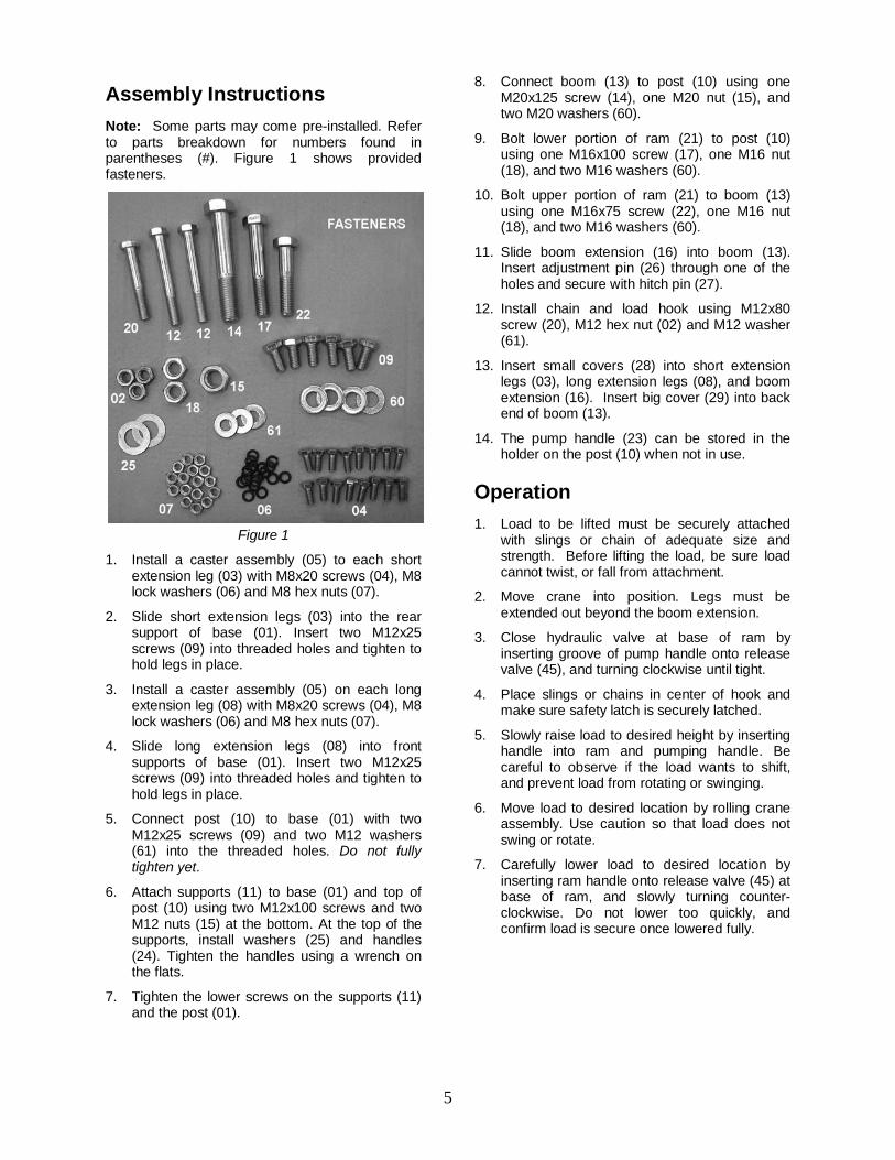
Assembly Instructions Note: Some parts may come pre-installed. Refer to parts breakdown for numbers found in parentheses (#). Figure 1 shows provided fasteners.
Figure 1
1. Install a caster assembly (05) to each short extension leg (03) with M8x20 screws (04), M8 lock washers (06) and M8 hex nuts (07).
2. Slide short extension legs (03) into the rear support of base (01). Insert two M12x25 screws (09) into threaded holes and tighten to hold legs in place.
3. Install a caster assembly (05) on each long extension leg (08) with M8x20 screws (04), M8 lock washers (06) and M8 hex nuts (07).
4. Slide long extension legs (08) into front supports of base (01). Insert two M12x25 screws (09) into threaded holes and tighten to hold legs in place.
5. Connect post (10) to base (01) with two M12x25 screws (09) and two M12 washers (61) into the threaded holes. Do not fully tighten yet.
6. Attach supports (11) to base (01) and top of post (10) using two M12x100 screws and two M12 nuts (15) at the bottom. At the top of the supports, install washers (25) and handles (24). Tighten the handles using a wrench on the flats.
7. Tighten the lower screws on the supports (11) and the post (01).
8. Connect boom (13) to post (10) using one M20x125 screw (14), one M20 nut (15), and two M20 washers (60).
9. Bolt lower portion of ram (21) to post (10) using one M16x100 screw (17), one M16 nut (18), and two M16 washers (60).
10. Bolt upper portion of ram (21) to boom (13) using one M16x75 screw (22), one M16 nut (18), and two M16 washers (60).
11. Slide boom extension (16) into boom (13). Insert adjustment pin (26) through one of the holes and secure with hitch pin (27).
12. Install chain and load hook using M12x80 screw (20), M12 hex nut (02) and M12 washer (61).
13. Insert small covers (28) into short extension legs (03), long extension legs (08), and boom extension (16). Insert big cover (29) into back end of boom (13).
14. The pump handle (23) can be stored in the holder on the post (10) when not in use.
Operation 1. Load to be lifted must be securely attached
with slings or chain of adequate size and strength. Before lifting the load, be sure load cannot twist, or fall from attachment.
2. Move crane into position. Legs must be extended out beyond the boom extension.
3. Close hydraulic valve at base of ram by inserting groove of pump handle onto release valve (45), and turning clockwise until tight.
4. Place slings or chains in center of hook and make sure safety latch is securely latched.
5. Slowly raise load to desired height by inserting handle into ram and pumping handle. Be careful to observe if the load wants to shift, and prevent load from rotating or swinging.
6. Move load to desired location by rolling crane assembly. Use caution so that load does not swing or rotate.
7. Carefully lower load to desired location by inserting ram handle onto release valve (45) at base of ram, and slowly turning counter-clockwise. Do not lower too quickly, and confirm load is secure once lowered fully.

6
Parts Ordering Replacement Parts
To order parts or reach our service department, call 1-800-274-6848 Monday through Friday (see our website for business hours, www.walteremeier.com). Having the Model Number and Serial Number of your machine available when you call will allow us to serve you quickly and accurately.
Hydraulic Crane Assembly – Exploded View

7
Hydraulic Crane Assembly – Parts List
Index No. Part No. Description Size Qty
01 ............. JHC200X-01 ............Base ...................................................................................................... 1 02 ............. TS-1540081 .............Hex Nut ..............................................................M12 ............................ 3 03 ............. JHC200X-03 ............Extension Leg (short)............................................................................. 2 04 ............. TS-1490031 .............Hex Cap Bolt ......................................................M8×20 ...................... 16 05 ............. JHC200X-05 ............Caster Assembly ................................................................................... 4 06 ............. TS-1551061 .............Lock Washer ......................................................M8 ............................ 16 07 ............. TS-1540061 .............Hex Nut ..............................................................M8 ............................ 16 08 ............. JHC200X-08 ............Extension Leg (long) .............................................................................. 2 09 ............. TS-1492011 .............Hex Cap Bolt ......................................................M12×25 ...................... 6 10 ............. JHC200X-10 ............Post ....................................................................................................... 1 11 ............. JHC200X-11 ............Support ................................................................................................. 2 12 ............. TS-1492101 .............Hex Cap Bolt ......................................................M12×100 .................... 2 13 ............. JHC200X-13 ............Boom .................................................................................................... 1 14 ............. JHC200X-14 ............Hex Cap Bolt ......................................................M20×125 .................... 1 15 ............. TS-1540121 .............Hex Nut ..............................................................M20 ............................ 1 16 ............. JHC200X-16 ............Boom Extension .................................................................................... 1 17 ............. JHC200X-17 ............Hex Cap Bolt ......................................................M16×100 .................... 1 18 ............. TS-1540101 .............Hex Nut ..............................................................M16 ............................ 2 19 ............. JHC200X-19 ............Load Hook w/chain ................................................................................ 1 20 ............. TS-1499141 .............Hex Cap Bolt ......................................................M12×80 ...................... 1 21 ............. JFHC200X-6 ............Ram Assembly ...................................................................................... 1 22 ............. JHC200X-22 ............Hex Cap Bolt ......................................................M16×75 ...................... 1 23 ............. JHC200X-23 ............Handle................................................................................................... 1 24 ............. JHC200X-24 ............Steering Handle ..................................................................................... 2 25 ............. JHC200X-25 ............Washer...............................................................D32x16.5x3T mm ....... 2 26 ............. JHC200X-26 ............Adjustment Pin ...................................................................................... 1 27 ............. JHC200X-27 ............Hitch Pin ................................................................................................ 1 28 ............. JHC200X-28 ............Small Cover ........................................................................................... 5 29 ............. JHC200X-29 ............Big Cover .............................................................................................. 1 60 ............. TS-155010 ...............Flat Washer ........................................................16mm ......................... 4 61 ............. TS-2360121 .............Flat Washer ........................................................12mm ......................... 3 ................. JHC200X-RK ...........Ram Repair Kit (not shown) ................................................................... 1 ................. JHC200X-ID.............I.D. Label (not shown)............................................................................ 1 ................. JHC200X-WL ...........Warning Label (not shown) .................................................................... 1 ................. JHC200X-CL ............Capacity Labels (set of 4: 1/2T,1T,1.5T,2T)(not shown) ......................... 1

8
Hydraulic Ram – Exploded View

9
Hydraulic Ram – Parts List
Index No. Part No. Description Size Qty ................. JFHC200X-6 ............Hydraulic Ram Assembly ....................................................................... 1 30 ............. JFHC200X-30 ..........Valve Body ............................................................................................ 1 31 ............. JFHC200X-31 ..........Copper Washer * ................................................M46 ............................ 1 32 ............. JFHC200X-32 ..........Cylinder ................................................................................................. 1 33 ............. JFHC200X-33 ..........O-ring *...............................................................M40x5.5 ..................... 1 34 ............. JFHC200X-34 ..........O-ring Retainer * ................................................M31.3x3.55 ................ 1 35 ............. JFHC200X-35 ..........Ram ...................................................................................................... 1 36 ............. JFHC200X-36 ..........Top Nut ..............................................................M48 ............................ 1 37 ............. JFHC200X-37 ..........O-ring *...............................................................M33.5x3.55 ................ 1 38 ............. JFHC200X-38 ..........Gasket * .............................................................M70x1 ........................ 1 39 ............. JFHC200X-39 ..........Oil Chamber .......................................................................................... 1 40 ............. JFHC200X-40 ..........Oil Plug * ............................................................M15x9.5 ..................... 1 41 ............. JFHC200X-41 ..........Seal Ring * .........................................................M81x4 ........................ 1 42 ............. JFHC200X-42 ..........Tube ...................................................................................................... 1 43 ............. SB-6MM...................Steel Ball ............................................................M6 .............................. 1 44 ............. JFHC200X-44 ..........Seal Ring * .........................................................M88x6 ........................ 1 45 ............. JFHC200X-45 ..........Release Valve ....................................................................................... 1 46 ............. SB-6MM...................Steel Ball ............................................................M6 .............................. 2 47 ............. JFHC200X-47 ..........Copper Washer * ................................................M18 ............................ 2 48 ............. JFHC200X-48 ..........Pump Cylinder ....................................................................................... 2 49 ............. JFHC200X-49 ..........O-ring *...............................................................M6.6x3 ....................... 2 50 ............. JFHC200X-50 ..........Back-up Ring * ...................................................M12x7 ........................ 2 51 ............. JFHC200X-51 ..........Plunger (s/n 12020001 and higher) ............................................................ 2 ................. JFHC200X-51A ........Plunger (previous to s/n 12020001) ........................................................... 1 52 ............. JFHC200X-52 ..........Link Pin ................................................................................................. 1 53 ............. JFHC200X-53 ..........Handle Socket ....................................................................................... 1 54 ............. JFHC200X-54 ..........Connecting Pin ...................................................................................... 3 55 ............. JFHC200X-55 ..........Cotter Pin .............................................................................................. 3 56 ............. JFHC200X-56 ..........Pin......................................................................M2x30 ........................ 1 57 ............. JFHC200X-57 ..........Bolt.....................................................................M14x45 ...................... 1 58 ............. JFHC200X-58 ..........Dust Seal ...........................................................M18.5x6 ..................... 2 ................. JFHC200X-RK .........Ram Repair Kit (includes items with asterisk *) ........................................

10
This page intentionally left blank

11
This page intentionally left blank

12
WALTER MEIER (Manufacturing) Inc.
427 New Sanford Road LaVergne, Tennessee 37086
Phone: 800-274-6848 www.jettools.com
www.waltermeier.com