Operating Instructions and Parts Manual 16-inch...
28
Operating Instructions and Parts Manual 16-inch Metalworking Band Saw Model VBS-1610 JET 427 New Sanford Road LaVergne, Tennessee 37086 Part No. M-414485 Ph.: 800-274-6848 Revision J 10/2018 www.jettools.com Copyright © 2014 JET
Transcript of Operating Instructions and Parts Manual 16-inch...

Operating Instructions and Parts Manual 16-inch Metalworking Band Saw Model VBS-1610
JET 427 New Sanford Road LaVergne, Tennessee 37086 Part No. M-414485 Ph.: 800-274-6848 Revision J 10/2018 www.jettools.com Copyright © 2014 JET
Tom Gauger
This .pdf document is bookmarked

2
1.0 Warranty and Service JET warrants every product it sells against manufacturers’ defects. If one of our tools needs service or repair, please contact Technical Service by calling 1-800-274-6846, 8AM to 5PM CST, Monday through Friday.
Warranty Period The general warranty lasts for the time period specified in the literature included with your product or on the official JET branded website.
• JET products carry a limited warranty which varies in duration based upon the product. (See chart below) • Accessories carry a limited warranty of one year from the date of receipt. • Consumable items are defined as expendable parts or accessories expected to become inoperable within a
reasonable amount of use and are covered by a 90 day limited warranty against manufacturer’s defects.
Who is Covered This warranty covers only the initial purchaser of the product from the date of delivery.
What is Covered This warranty covers any defects in workmanship or materials subject to the limitations stated below. This warranty does not cover failures due directly or indirectly to misuse, abuse, negligence or accidents, normal wear-and-tear, improper repair, alterations or lack of maintenance. JET woodworking machinery is designed to be used with Wood. Use of these machines in the processing of metal, plastics, or other materials outside recommended guidelines may void the warranty. The exceptions are acrylics and other natural items that are made specifically for wood turning.
Warranty Limitations Woodworking products with a Five Year Warranty that are used for commercial or industrial purposes default to a Two Year Warranty. Please contact Technical Service at 1-800-274-6846 for further clarification.
How to Get Technical Support Please contact Technical Service by calling 1-800-274-6846. Please note that you will be asked to provide proof of initial purchase when calling. If a product requires further inspection, the Technical Service representative will explain and assist with any additional action needed. JET has Authorized Service Centers located throughout the United States. For the name of an Authorized Service Center in your area call 1-800-274-6846 or use the Service Center Locator on the JET website.
More Information JET is constantly adding new products. For complete, up-to-date product information, check with your local distributor or visit the JET website.
How State Law Applies This warranty gives you specific legal rights, subject to applicable state law.
Limitations on This Warranty JET LIMITS ALL IMPLIED WARRANTIES TO THE PERIOD OF THE LIMITED WARRANTY FOR EACH PRODUCT. EXCEPT AS STATED HEREIN, ANY IMPLIED WARRANTIES OF MERCHANTABILITY AND FITNESS FOR A PARTICULAR PURPOSE ARE EXCLUDED. SOME STATES DO NOT ALLOW LIMITATIONS ON HOW LONG AN IMPLIED WARRANTY LASTS, SO THE ABOVE LIMITATION MAY NOT APPLY TO YOU. JET SHALL IN NO EVENT BE LIABLE FOR DEATH, INJURIES TO PERSONS OR PROPERTY, OR FOR INCIDENTAL, CONTINGENT, SPECIAL, OR CONSEQUENTIAL DAMAGES ARISING FROM THE USE OF OUR PRODUCTS. SOME STATES DO NOT ALLOW THE EXCLUSION OR LIMITATION OF INCIDENTAL OR CONSEQUENTIAL DAMAGES, SO THE ABOVE LIMITATION OR EXCLUSION MAY NOT APPLY TO YOU. JET sells through distributors only. The specifications listed in JET printed materials and on official JET website are given as general information and are not binding. JET reserves the right to effect at any time, without prior notice, those alterations to parts, fittings, and accessory equipment which they may deem necessary for any reason whatsoever. JET® branded products are not sold in Canada by JPW Industries, Inc.
Product Listing with Warranty Period 90 Days – Parts; Consumable items 1 Year – Motors; Machine Accessories 2 Year – Metalworking Machinery; Electric Hoists, Electric Hoist Accessories; Woodworking Machinery used for industrial or commercial purposes 5 Year – Woodworking Machinery Limited Lifetime – JET Parallel clamps; VOLT Series Electric Hoists; Manual Hoists; Manual Hoist Accessories; Shop Tools; Warehouse & Dock products; Hand Tools; Air Tools
NOTE: JET is a division of JPW Industries, Inc. References in this document to JET also apply to JPW Industries, Inc., or any of its successors in interest to the JET brand.

3
2.0 Table of contents Section Page 1.0 Warranty and Service ..................................................................................................................................... 2 2.0 Table of contents ............................................................................................................................................ 3 3.0 Safety warnings .............................................................................................................................................. 4 4.0 About this manual .......................................................................................................................................... 5 5.0 Specifications ................................................................................................................................................. 6 6.0 Uncrating and assembly ................................................................................................................................. 7 7.0 Installation ...................................................................................................................................................... 7 8.0 Electrical connections .................................................................................................................................... 7
8.1 Voltage conversion ..................................................................................................................................... 7 8.2 Three-phase test run .................................................................................................................................. 7
9.0 Controls .......................................................................................................................................................... 8 10.0 Adjustments ................................................................................................................................................. 9
10.1 Blade tensioning ....................................................................................................................................... 9 10.2 Blade tracking ........................................................................................................................................... 9 10.3 Blade guide adjustment ............................................................................................................................ 9 10.4 Top guide adjustment ............................................................................................................................. 10 10.5 Changing saw blades ............................................................................................................................. 10 10.6 Work lamp bulb ...................................................................................................................................... 10
11.0 Blade selection ........................................................................................................................................... 10 11.1 Material composition .............................................................................................................................. 10 11.2 Tooth shape ........................................................................................................................................... 10 11.3 Set type .................................................................................................................................................. 11 11.4 Gage ....................................................................................................................................................... 11 11.5 Kerf ......................................................................................................................................................... 11 11.6 Width ...................................................................................................................................................... 11 11.7 Blade breakage ...................................................................................................................................... 11
12.0 Welder operation ........................................................................................................................................ 11 12.1 Shearing ................................................................................................................................................. 11 12.2 Removing Teeth ..................................................................................................................................... 12 12.3 Welding .................................................................................................................................................. 12 12.4 Annealing ............................................................................................................................................... 13 12.5 Blade grinding ........................................................................................................................................ 14 12.6 Secondary Annealing ............................................................................................................................. 14 12.7 Welder Clean-Up .................................................................................................................................... 14
13.0 Band saw operation ................................................................................................................................... 14 13.1 Blade break-in procedure ....................................................................................................................... 14 13.2 Setting blade speed ................................................................................................................................ 14 13.3 Evaluating cutting efficiency ................................................................................................................... 15
14.0 User-maintenance ...................................................................................................................................... 15 14.1 Lubrication schedule .............................................................................................................................. 15 14.2 Gearbox oil ............................................................................................................................................. 15
15.0 Troubleshooting ......................................................................................................................................... 16 15.1 Operating problems ................................................................................................................................ 16 15.2 Mechanical and electrical problems ....................................................................................................... 17 15.3 Welded blade inspection ........................................................................................................................ 18 15.4 Welder mechanical problems ................................................................................................................. 19
16.0 Speed and pitch chart ................................................................................................................................ 20 17.0 Typical Band Saw Operations .................................................................................................................... 21 18.0 Replacement Parts ..................................................................................................................................... 21
18.1.1 VBS-1610 Band Saw – Exploded View ............................................................................................... 22 18.1.2 VBS-1610 Band Saw (Welder Assembly) – Exploded View ............................................................... 23 18.1.3 VBS-1610 Band Saw – Parts List ........................................................................................................ 24
19.0 Electrical diagram (VBS-1610) ................................................................................................................... 28

4
3.0 Safety warnings 1. Read and understand the entire owner's
manual before attempting assembly or operation.
2. Read and understand the warnings posted on the machine and in this manual. Failure to comply with all of these warnings may cause serious injury.
3. Replace the warning labels if they become obscured or removed.
4. This band saw is designed and intended for use by properly trained and experienced personnel only. If you are not familiar with the proper and safe operation of a band saw, do not use until proper training and knowledge have been obtained.
5. Do not use this band saw for other than its intended use. If used for other purposes, JET disclaims any real or implied warranty and holds itself harmless from any injury that may result from that use.
6. Always wear approved safety glasses/face shields while using this band saw. Everyday eyeglasses only have impact resistant lenses; they are not safety glasses.
7. Before operating this band saw, remove tie, rings, watches and other jewelry, and roll sleeves up past the elbows. Remove all loose clothing and confine long hair. Non-slip footwear or anti-skid floor strips are recommended. Do not wear gloves.
8. Wear ear protectors (plugs or muffs) during extended periods of operation.
9. Do not operate this machine while tired or under the influence of drugs, alcohol or any medication.
10. Make certain the switch is in the OFF position before connecting the machine to the power supply.
11. Make certain the machine is properly grounded.
12. Make all machine adjustments or maintenance with the machine unplugged from the power source.
13. Remove adjusting keys and wrenches. Form a habit of checking to see that keys and adjusting wrenches are removed from the machine before turning it on.
14. Keep safety guards in place at all times when the machine is in use. If removed for
maintenance purposes, use extreme caution and replace the guards immediately after completion of maintenance.
15. Check damaged parts. Before further use of the machine, a guard or other part that is damaged should be carefully checked to determine that it will operate properly and perform its intended function. Check for alignment of moving parts, binding of moving parts, breakage of parts, mounting and any other conditions that may affect its operation. A guard or other part that is damaged should be properly repaired or replaced.
16. Provide for adequate space surrounding work area and non-glare, overhead lighting.
17. Keep the floor around the machine clean and free of scrap material, oil and grease.
18. Keep visitors a safe distance from the work area. Keep children away.
19. Make your workshop child proof with padlocks, master switches or by removing starter keys.
20. Give your work undivided attention. Looking around, carrying on a conversation and “horse-play” are careless acts that can result in serious injury.
21. Maintain a balanced stance at all times so that you do not fall into the blade or other moving parts. Do not overreach or use excessive force to perform any machine operation.
22. Use the right tool at the correct speed and feed rate. Do not force a tool or attachment to do a job for which it was not designed. The right tool will do the job better and more safely.
23. Use recommended accessories; improper accessories may be hazardous.
24. Maintain tools with care. Keep saw blades sharp and clean for the best and safest performance. Follow instructions for lubricating and changing accessories.
25. Turn off the machine before cleaning. Use a brush or compressed air to remove chips or debris — do not use your bare hands.
26. Do not stand on the machine. Serious injury could occur if the machine tips over.
27. Never leave the machine running unattended. Turn the power off and do not leave the machine until it comes to a complete stop.
28. Remove loose items and unnecessary work pieces from the area before starting the machine.
29. Keep hands out of the line of saw blade.
30. Always use push sticks when cutting small material.
5
31. Raise or lower blade guide only when machine has been turned off and blade has stopped moving.
32. Always wear leather gloves when handling saw blades. The operator should not wear gloves when operating the band saw.
33. Do not allow the saw blade to rest against the workpiece when the saw is not running.
34. The saw must be stopped and the electrical supply must be cut off before any blade replacement, drive belt replacement, or any periodic service or maintenance is performed on the machine.
35. Remove cut off pieces carefully, keeping hands away from the blade. The saw must be stopped and the electrical supply cut off or machine unplugged before reaching into the cutting area.
36. Don’t use in dangerous environment. Don’t use power tools in damp or wet location, or expose them to rain. Keep work area well lighted.
Familiarize yourself with the following safety notices used in this manual:
This means that if precautions are not heeded, it may result in minor injury and/or possible machine damage.
This means that if precautions are not heeded, it may result in serious injury or possibly even death.
4.0 About this manual This manual is provided by JET covering the safe operation and maintenance procedures for a JET Model VBS-1610 Band Saw. This manual contains instructions on installation, safety precautions, general operating procedures, maintenance instructions and parts breakdown. Your machine has been designed and constructed to provide consistent, long-term operation if used in accordance with the instructions as set forth in this document.
If there are questions or comments, please contact your local supplier or JET. JET can also be reached at our web site: www.jettools.com.
Retain this manual for future reference. If the machine transfers ownership, the manual should accompany it.
Read and understand the entire contents of this manual before attempting assembly or operation! Failure to comply may cause serious injury!
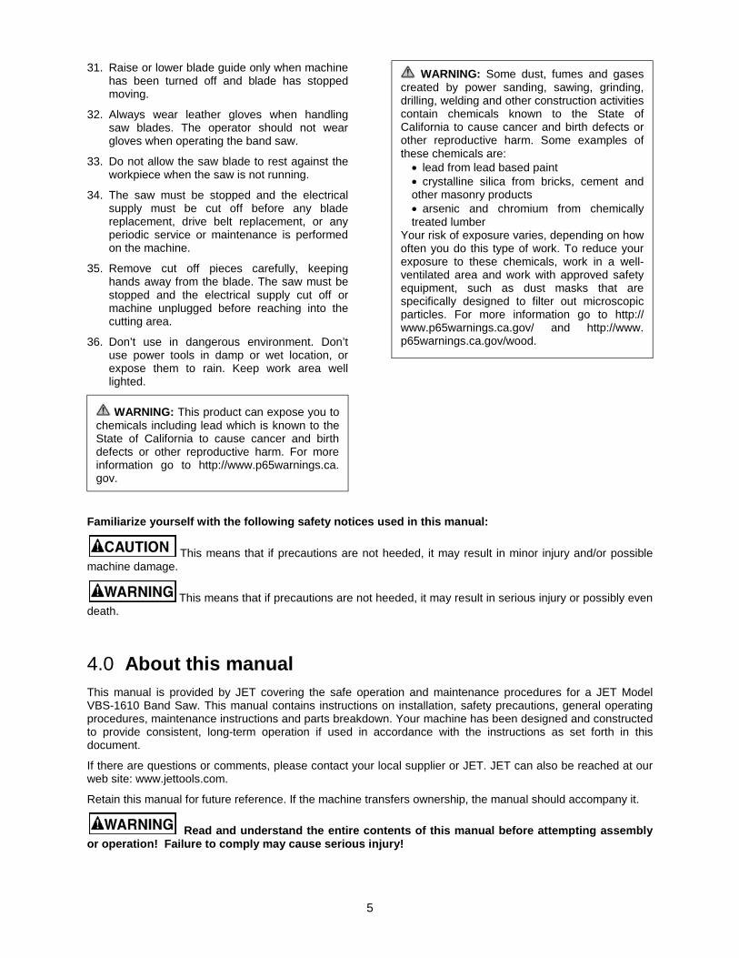
WARNING: This product can expose you to chemicals including lead which is known to the State of California to cause cancer and birth defects or other reproductive harm. For more information go to http://www.p65warnings.ca. gov.
WARNING: Some dust, fumes and gases created by power sanding, sawing, grinding, drilling, welding and other construction activities contain chemicals known to the State of California to cause cancer and birth defects or other reproductive harm. Some examples of these chemicals are:
• lead from lead based paint • crystalline silica from bricks, cement and other masonry products • arsenic and chromium from chemically treated lumber
Your risk of exposure varies, depending on how often you do this type of work. To reduce your exposure to these chemicals, work in a well-ventilated area and work with approved safety equipment, such as dust masks that are specifically designed to filter out microscopic particles. For more information go to http:// www.p65warnings.ca.gov/ and http://www. p65warnings.ca.gov/wood.

6
5.0 Specifications Model number ......................................................................................................................................... VBS-1610 Stock number .............................................................................................................................................. 414485 Blade speed ............................................................................................................................................... variable Low range ...................................................................................................................................... 82-330 SFM High range .................................................................................................................................. 985-3950 SFM Capacities: Height (max. thickness) ................................................................................................................ 10” (254 mm) Throat (max. width) ................................................................................................................ 15-1/2” (394 mm) Welder capacity ............................................................................................................................. 5/8" (16 mm) Motor ........................................................ TEFC, 2HP (1.5kW), 3PH, 230/460V (prewired 230V), 6.2/3.1A, 60Hz Table size ........................................................................................................................ 22” x 24” (559 x 610 mm) Table height from floor at 90° .......................................................................................................... 40” (1016 mm) Table tilt: Front and Back ......................................................................................................................................... 8 deg. Right ....................................................................................................................................................... 15 deg. Left ......................................................................................................................................................... 12 deg. Blade length (approximate) ........................................................................................................................ 123-1/2” Blade width, maximum ...................................................................................................................................... 5/8” Overall height ............................................................................................................................ 72-1/2” (1842 mm) Floor space required ................................................................................................................................. 37” x 28” Gearbox oil capacity .................................................................................................................. 2500 cc (0.66 gal.) Weights: Net ............................................................................................................................................ 900 lbs. (408 kg) Shipping ................................................................................................................................. 1015 lbs. (460 kg)
The specifications in this manual were current at time of publication, but because of our policy of continuous improvement, JET reserves the right to change specifications at any time and without prior notice, without incurring obligations.

7
6.0 Uncrating and assembly 1. Finish uncrating the band saw. Contact your
distributor if any damage has occurred during shipping.
2. Remove any preservative with kerosene or diesel oil. Do not use gasoline, paint thinner, or any cellulose-based product, as these will damage painted surfaces.
3. Remove two socket head cap screws from left side of vertical column. Attach shear assembly (A, Figure 1) to column by inserting hex cap screws.
4. Place rip fence onto table and tighten with locking knob.
Figure 1
7.0 Installation 1. Remove three (3) nuts and washers holding
band saw to shipping crate bottom.
2. Use the lifting ring to lift band saw into its permanent location. For best performance, band saw should be bolted to floor after a level position has been found.
3. Using a square, adjust table 90 degrees to blade, both front to back and side to side. Loosen the hex cap screws below the table to move it and tighten to hold table in place. If necessary, adjust the pointers to zero should they read different once table is perpendicular to blade in both directions.
4. To level the machine, place a machinist's level on the table and observe in both directions.
5. Use metal shims under the appropriate hold down screw. Tighten screw and recheck for level.
6. Adjust with additional shims, as required, until table is level when all mounting screws (or nuts) are tight.
8.0 Electrical connections
All electrical connections must be done by a qualified electrician. All adjustments or repairs must be done with machine disconnected from power source. Failure to comply may cause serious injury. The VBS-1610 Band Saw is rated at 230/460V and comes from the factory prewired 230V.
You may either connect a proper UL-listed plug suitable for 230 volt operation, or "hard-wire" the machine directly to your electrical panel provided there is a disconnect near the machine for the operator.
The band saw must be grounded. A qualified electrician can make the proper electrical connections and confirm the power on site is compatible with the saw.
Before connecting to power source, make sure switch is in off position.
8.1 Voltage conversion To switch to 460V operation:
1. Switch the incoming leads in the motor junction box (follow wiring diagram on inside cover of motor junction box).
2. Switch the jumper wires on the circuit board. Remove control panel from saw body and change the jumper wires according to the list in section 19.0, Electrical diagram.
3. If a plug is to be used, install a proper UL-listed plug suitable for 460V operation.
IMPORTANT: Consult the diagrams in section 19.0 for any clarification of these changes on 230V to 460V conversion.
8.2 Three-phase test run After wiring the band saw, you should check that the wires have been connected properly. Connect machine to power source and turn it on for an instant to watch direction of blade movement.
If blade runs upward instead of downward, disconnect machine from power, and switch any two of the three leads in the motor junction box (see section 19.0, Electrical diagram).
8
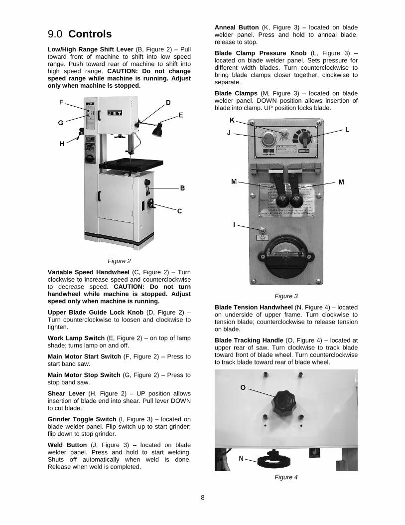
9.0 Controls Low/High Range Shift Lever (B, Figure 2) – Pull toward front of machine to shift into low speed range. Push toward rear of machine to shift into high speed range. CAUTION: Do not change speed range while machine is running. Adjust only when machine is stopped.
Figure 2
Variable Speed Handwheel (C, Figure 2) – Turn clockwise to increase speed and counterclockwise to decrease speed. CAUTION: Do not turn handwheel while machine is stopped. Adjust speed only when machine is running.
Upper Blade Guide Lock Knob (D, Figure 2) –Turn counterclockwise to loosen and clockwise to tighten.
Work Lamp Switch (E, Figure 2) – on top of lamp shade; turns lamp on and off.
Main Motor Start Switch (F, Figure 2) – Press to start band saw.
Main Motor Stop Switch (G, Figure 2) – Press to stop band saw.
Shear Lever (H, Figure 2) – UP position allows insertion of blade end into shear. Pull lever DOWN to cut blade.
Grinder Toggle Switch (I, Figure 3) – located on blade welder panel. Flip switch up to start grinder; flip down to stop grinder.
Weld Button (J, Figure 3) – located on blade welder panel. Press and hold to start welding. Shuts off automatically when weld is done. Release when weld is completed.
Anneal Button (K, Figure 3) – located on blade welder panel. Press and hold to anneal blade, release to stop.
Blade Clamp Pressure Knob (L, Figure 3) – located on blade welder panel. Sets pressure for different width blades. Turn counterclockwise to bring blade clamps closer together, clockwise to separate.
Blade Clamps (M, Figure 3) – located on blade welder panel. DOWN position allows insertion of blade into clamp. UP position locks blade.
Figure 3
Blade Tension Handwheel (N, Figure 4) – located on underside of upper frame. Turn clockwise to tension blade; counterclockwise to release tension on blade.
Blade Tracking Handle (O, Figure 4) – located at upper rear of saw. Turn clockwise to track blade toward front of blade wheel. Turn counterclockwise to track blade toward rear of blade wheel.
Figure 4

9
Table Tilt Mechanism – located under work table. To tilt table left or right, loosen two socket head cap screws (P, Figure 5) at rear of mechanism. To level table front to back, loosen four socket head cap screws (Q, Figure 6) on either side of mechanism.
Figure 5
Figure 6
10.0 Adjustments
All adjustments or repairs to machine must be done with power off and machine disconnected from power source. Failure to comply may cause serious injury.
10.1 Blade tensioning 1. Raise upper blade guide by loosening lock
knob (A, Figure 7) and lifting blade guide handle (B, Figure 7) to its highest position.
Figure 7
2. Apply finger pressure to blade. Travel from vertical should be approximately 3/8" each way.
3. To tighten blade, turn handwheel (C, Figure 7) clockwise. To loosen blade, turn handwheel counterclockwise.
4. Use blade tension indicator (D, Figure 8) as reference only. Blade should be tensioned using the finger pressure method.
Figure 8
10.2 Blade tracking Blade tracking may be required periodically depending upon blade size and tension. The blade must be tensioned as outlined in section 10.1 Blade tensioning. Disconnect machine from power source and open upper blade wheel door. Shift high-low gear box lever into neutral position. Turn upper blade wheel by hand while observing blade position on upper blade wheel. If adjustment is necessary:
1. Turn blade tracking knob (E, Figure 8) clockwise to track blade toward front of blade wheel.
2. Turn tracking knob counterclockwise to track blade toward rear of blade wheel. Blade should run next to, but not against, the wheel flange.
Note: Upper and lower blade guides should be moved away and left loose from the blade while tracking adjustments are being made.
10.3 Blade guide adjustment
Blade guides must be properly adjusted or damage may occur to blade and/or guides.
Guard has been removed to show detail. Always operate saw with guard in place and properly adjusted. Failure to comply may cause serious injury.
10
Blade guide adjustment has been set by the manufacturer. Should future adjustment be needed, proceed as follows.
1. Loosen upper blade guide lock knob and raise guide assembly to half-way between table and head, then tighten lock knob
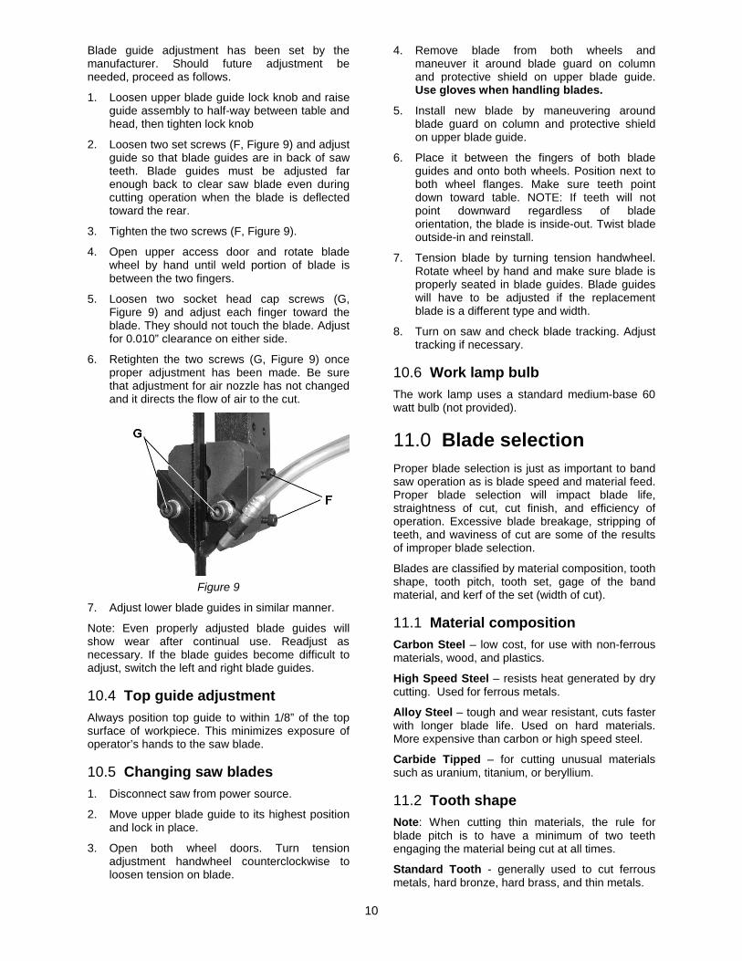
2. Loosen two set screws (F, Figure 9) and adjust guide so that blade guides are in back of saw teeth. Blade guides must be adjusted far enough back to clear saw blade even during cutting operation when the blade is deflected toward the rear.
3. Tighten the two screws (F, Figure 9).
4. Open upper access door and rotate blade wheel by hand until weld portion of blade is between the two fingers.
5. Loosen two socket head cap screws (G, Figure 9) and adjust each finger toward the blade. They should not touch the blade. Adjust for 0.010” clearance on either side.
6. Retighten the two screws (G, Figure 9) once proper adjustment has been made. Be sure that adjustment for air nozzle has not changed and it directs the flow of air to the cut.
Figure 9
7. Adjust lower blade guides in similar manner.
Note: Even properly adjusted blade guides will show wear after continual use. Readjust as necessary. If the blade guides become difficult to adjust, switch the left and right blade guides.
10.4 Top guide adjustment Always position top guide to within 1/8” of the top surface of workpiece. This minimizes exposure of operator’s hands to the saw blade.
10.5 Changing saw blades 1. Disconnect saw from power source.
2. Move upper blade guide to its highest position and lock in place.
3. Open both wheel doors. Turn tension adjustment handwheel counterclockwise to loosen tension on blade.
4. Remove blade from both wheels and maneuver it around blade guard on column and protective shield on upper blade guide. Use gloves when handling blades.
5. Install new blade by maneuvering around blade guard on column and protective shield on upper blade guide.
6. Place it between the fingers of both blade guides and onto both wheels. Position next to both wheel flanges. Make sure teeth point down toward table. NOTE: If teeth will not point downward regardless of blade orientation, the blade is inside-out. Twist blade outside-in and reinstall.
7. Tension blade by turning tension handwheel. Rotate wheel by hand and make sure blade is properly seated in blade guides. Blade guides will have to be adjusted if the replacement blade is a different type and width.
8. Turn on saw and check blade tracking. Adjust tracking if necessary.
10.6 Work lamp bulb The work lamp uses a standard medium-base 60 watt bulb (not provided).
11.0 Blade selection Proper blade selection is just as important to band saw operation as is blade speed and material feed. Proper blade selection will impact blade life, straightness of cut, cut finish, and efficiency of operation. Excessive blade breakage, stripping of teeth, and waviness of cut are some of the results of improper blade selection.
Blades are classified by material composition, tooth shape, tooth pitch, tooth set, gage of the band material, and kerf of the set (width of cut).
11.1 Material composition Carbon Steel – low cost, for use with non-ferrous materials, wood, and plastics.
High Speed Steel – resists heat generated by dry cutting. Used for ferrous metals.
Alloy Steel – tough and wear resistant, cuts faster with longer blade life. Used on hard materials. More expensive than carbon or high speed steel.
Carbide Tipped – for cutting unusual materials such as uranium, titanium, or beryllium.
11.2 Tooth shape Note: When cutting thin materials, the rule for blade pitch is to have a minimum of two teeth engaging the material being cut at all times.
Standard Tooth - generally used to cut ferrous metals, hard bronze, hard brass, and thin metals.
11
Skip Tooth - have better chip clearance (larger gullet) and are used on softer, non-ferrous materials such as aluminum, copper, magnesium, and soft brass.
Hook Tooth - provides a chip breaker and has less tendency to gum up in softer materials. Used in the same materials as skip tooth but can be fed faster than standard or skip tooth blades.
11.3 Set type Straight Set – used for free cutting non-ferrous materials; i.e., aluminum, magnesium, plastics, and wood.
Wavy Set – used on materials of varying thickness (pipe, tubing, and structural shapes).
Raker Set – used in large cuts on thick plate and bar stock where finish of cut is not as important as speed.
11.4 Gage Gage is the thickness of material from which the blade is produced. The thicker the material, the stronger the blade.
11.5 Kerf Kerf is the width of a cut. Kerf will vary according to the set of the blade teeth.
11.6 Width The thinner the blade, the tighter will be the minimum radius of cut. Always use widest blade possible for the job.
General rules for blade selection:
• Select coarser pitch blades for thicker or softer material.
• Select finer pitch blades for thinner or harder material.
• Use fine pitch blades to obtain a smooth finish.
• Use coarse pitch blades to obtain faster cutting speeds (thick material).
• To prevent premature blade wear, use fastest practical speed.
• Adjust feed rate to ensure continuous cutting action.
• Run the bandsaw with blade centered in upper and lower guides, and guide fingers adjusted as close as possible without touching the blade or weld joint.
Never adjust guide fingers while blade is running. Failure to comply may cause serious injury.
11.7 Blade breakage Band saw blades are subject to high stresses and breakage may sometimes be unavoidable. However, many factors can be controlled to help prevent most blade breakage. Here are some common causes for breakage:
1. Misalignment of blade guides. 2. Feeding workpiece too quickly. 3. Using a wide blade to cut a short radius curve. 4. Excessive tension. 5. Teeth are dull or improperly set. 6. Upper guides are set too high off the
workpiece. 7. Faulty weld on blade.
12.0 Welder operation
Wear eye protection while operating welder. Use care when handling blade after welding to avoid burns.
The welding procedure involves the following steps: Shearing the blade, grinding teeth to allow for the weld area, the actual welding, inspection of blade, annealing, grinding and a final inspection of blade. This procedure can be accomplished using the shear and welder assemblies on your band saw. Proceed as follows:
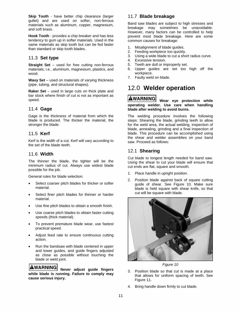
12.1 Shearing Cut blade to longest length needed for band saw. Using the shear to cut your blade will ensure that cut ends are flat, square and smooth.
1. Place handle in upright position.
2. Position blade against back of square cutting guide of shear. See Figure 10. Make sure blade is held square with shear knife, so that cut will be square with blade.
Figure 10
3. Position blade so that cut is made at a place that allows for uniform spacing of teeth. See Figure 11.
4. Bring handle down firmly to cut blade.
12
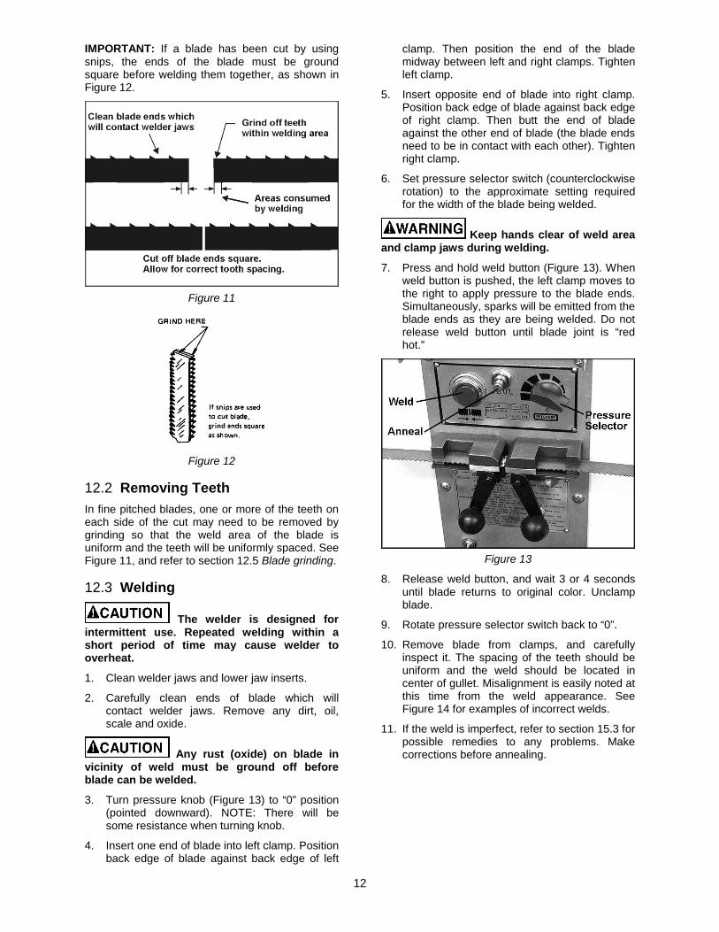
IMPORTANT: If a blade has been cut by using snips, the ends of the blade must be ground square before welding them together, as shown in Figure 12.
Figure 11
Figure 12
12.2 Removing Teeth In fine pitched blades, one or more of the teeth on each side of the cut may need to be removed by grinding so that the weld area of the blade is uniform and the teeth will be uniformly spaced. See Figure 11, and refer to section 12.5 Blade grinding.
12.3 Welding
The welder is designed for intermittent use. Repeated welding within a short period of time may cause welder to overheat.
1. Clean welder jaws and lower jaw inserts.
2. Carefully clean ends of blade which will contact welder jaws. Remove any dirt, oil, scale and oxide.
Any rust (oxide) on blade in vicinity of weld must be ground off before blade can be welded.
3. Turn pressure knob (Figure 13) to “0” position (pointed downward). NOTE: There will be some resistance when turning knob.
4. Insert one end of blade into left clamp. Position back edge of blade against back edge of left
clamp. Then position the end of the blade midway between left and right clamps. Tighten left clamp.
5. Insert opposite end of blade into right clamp. Position back edge of blade against back edge of right clamp. Then butt the end of blade against the other end of blade (the blade ends need to be in contact with each other). Tighten right clamp.
6. Set pressure selector switch (counterclockwise rotation) to the approximate setting required for the width of the blade being welded.
Keep hands clear of weld area and clamp jaws during welding.
7. Press and hold weld button (Figure 13). When weld button is pushed, the left clamp moves to the right to apply pressure to the blade ends. Simultaneously, sparks will be emitted from the blade ends as they are being welded. Do not release weld button until blade joint is “red hot.”
Figure 13
8. Release weld button, and wait 3 or 4 seconds until blade returns to original color. Unclamp blade.
9. Rotate pressure selector switch back to “0”.
10. Remove blade from clamps, and carefully inspect it. The spacing of the teeth should be uniform and the weld should be located in center of gullet. Misalignment is easily noted at this time from the weld appearance. See Figure 14 for examples of incorrect welds.
11. If the weld is imperfect, refer to section 15.3 for possible remedies to any problems. Make corrections before annealing.

13
Figure 14
12.4 Annealing The blade must now be annealed, or cooled at a controlled rate to prevent it becoming too brittle.
The general procedure follows. Specific procedure will depend upon blade type, as described in sections 12.4.1 through 12.4.3.
1. Turn pressure selector knob all the way to left so clamp jaws are closest to each other.
2. Insert blade into clamps so that weld area is centered between clamps. Secure blade in jaws with the clamp handles.
3. Quickly press and release (“jog”) the anneal button (Figure 13). Repeat jog process until you see a slightly red glow from weld area.
Do not press and hold the anneal push button. The weld will be overheated and will fail due to excessive heat.
4. Release both blade clamps, allow blade to cool, then remove blade from clamps.
5. Check weld integrity. Bend blade to form a radius at point of weld. The size of the radius should be approximately the same as radius of band saw drive wheel. The weld must hold and not break or crack after forming the radius. If the weld breaks, cut away welded area and repeat welding-annealing process.
6. Check to make sure welded section is same thickness as rest of blade. If not, grind off
excess weld material using the grinder. Refer to section 12.5, Blade grinding.
If blade is thicker at the weld than at the rest of the blade, using the blade may damage the guides.
The following are variations of the general procedure, based upon blade type:
12.4.1 Carbon steel blades 1. Press and jog the annealing switch button until
weld is a "dull cherry" to "cherry red" color.
2. Allow blade to cool slowly by decreasing jogging frequency.
12.4.2 Carbon steel hard back blades 1. Heat blade slowly until weld becomes a deep
blue color.
2. Continue to heat by jogging the anneal button until the width of the blue color is one-half the length of the band exposed between the jaws.
3. Do not overheat or the temper of the band will be damaged. Caution - Do not heat beyond the "blue" stage. If the band begins to show any red color, it is too hot. Cool quickly by releasing the anneal button.
Figure 15
12.4.3 Bi-Metal blades 1. Heat blade slowly by jogging the annealing
switch button until weld just begins to emit light (dull red color). The desired color may not always be visible in normal room light - always shade the weld area with your hand.
2. Cool the weld quickly by releasing the annealing button.
3. Follow this procedure before and after grinding bimetal blades.

14
12.5 Blade grinding
Keep hands away from rotating grinding wheel. Failure to comply may cause serious injury. Always heed the indicator light – when glowing, it warns that the grinder motor is running.
After annealing, the blade must be ground to remove excess metal or flash from the weld. With the teeth facing out, grind the weld carefully (Figure 16). Do not hit the teeth, or grind deeper than the weld, burn, or overheat the weld area. Be sure to remove flash from back edge of blade. Any flash or "stub" teeth which project beyond the normal set or height of the other teeth must be ground off.
Figure 17 illustrates some unacceptable grindings.
Figure 16
Figure 17
12.6 Secondary Annealing Anneal the weld 2 to 3 times again after grinding.
12.7 Welder Clean-Up It is important that the welder jaws be kept clean at all times. The jaws and inserts must be wiped or scraped clean after every weld. Doing this will ensure better welds by:
1. Holding proper alignment.
2. Preventing flash from becoming embedded in the blade.
3. Preventing shorts or poor electrical contact.
13.0 Band saw operation Consult section 9.0 for identification of the controls.
Unlock the control panel using the provided key.
Never operate band saw without blade and wheel covers in place and secured.
13.1 Blade break-in procedure New blades are very sharp and therefore have a tooth geometry that is easily damaged if a careful break-in procedure is not followed. Consult the blade manufacturer’s literature for break-in of specific blades on specific materials. The following procedure will be adequate, however, for break-in of JET-supplied blades on lower alloy ferrous materials.
1. Use a section of round stock.
2. Operate the saw at low speed. Start the cut with a very light feed rate.
3. When the saw has completed about 1/3 of the cut, increase the feed rate slightly and allow the saw to complete the cut.
4. Keep the feed rate at the same setting and begin a second cut on the same or similar workpiece.
5. When the saw has completed about 1/3 of the cut, increase the feed rate while watching the chip formation until cutting is at its most efficient rate (refer to “Evaluating Cutting Efficiency” below). Allow the saw to complete the cut.
6. The blade is now considered ready for use.
13.2 Setting blade speed 1. Refer to Speed and Pitch chart in section 16.0.
Select speed setting for the material to be cut.
2. While machine is NOT running, move gear shift lever (B, Figure 2) to required speed setting (high or low).
Move gear shift lever only when machine is NOT running, to prevent damage to gearbox.
3. Start saw using the pushbutton.
4. Turn speed setting handwheel (C, Figure 2) to required speed. Turning handwheel clockwise increases speed; counterclockwise decreases speed.
Rotate speed setting handwheel only when machine is running.

15
13.3 Evaluating cutting efficiency The best way to determine whether a blade is cutting efficiently is to observe the chips formed by the cutting.
• If chip formation is powdery, then the feed rate is too light, or blade is dull.
• If the chips formed are curled, but colored – blue or straw colored from heat generated during the cut – then feed rate is excessive.
• If chips are slightly curled and not colored by heat, then the blade is sufficiently sharp and is cutting at its most efficient rate.
14.0 User-maintenance
Before doing maintenance on the machine, disconnect it from the electrical supply by pulling out the plug or switching off the main switch. Failure to comply may cause serious injury.
Use a brush to loosen accumulated chips and debris. Use a shop vacuum to remove the debris. Make sure the chip brush on the lower band wheel is properly adjusted.
If the power cord is worn, cut, or damaged in any way, have it replaced immediately.
Wipe off the rubber tires, and clean the tables after each day’s use.
14.1 Lubrication schedule • Upper Blade Guide Shaft – lightly grease
weekly. Clean after each day's use.
• Speed Change Handle – grease monthly with a light film on teeth and threads.
• Variable Pulley - insert a light weight grease into the grease fitting located on end of pulley shaft.
• Blade Tension Screw – grease monthly.
14.2 Gearbox oil The gearbox is prefilled with oil. Drain and refill the gearbox annually, or every 3000 hours of operation. Servo® SAE HP140 gear oil, or equivalent, is recommended.
Unscrew drain plug from bottom of gearbox and drain the oil. Reinstall plug and fill gearbox using the oil cup at top of gearbox. Capacity is approximately 2500 cc (0.66 gal).

16
15.0 Troubleshooting
15.1 Operating problems Table 1
Trouble Probable Cause Remedy
Saw blade is twisted.
Blade has been improperly welded. Re-weld blade. See section 12.3
Blade not installed properly. Set guide inserts closer, and increase blade tension.
Feeding workpiece too forcefully. Decrease feed rate.
Incorrect choice of blade. Use proper width blade for radius or wavy line cutting.
Cuts not straight.
Blade tooth has improper set. File to proper set or replace blade.
Inadequate blade tension. Increase tension.
Guide post too high. Set guide post closer to workpiece.
Feed rate too strong. Decrease feed rate.
Blade slips off wheel(s).
Inadequate blade tension. Increase tension.
Wheels not aligned properly. Contact technical service for adjustment of wheel alignment.
Blade quickly becomes dull.
Blade speed too fast. Use slower speed.
Wrong blade for the job. Use proper blade for workpiece.
Feed rate excessive. Decrease feed rate.
Blade warps.
Dull blade. Sharpen or replace blade.
Guide post not fixed properly. Fix guide post in position.
Blade not tensioned enough. Increase tension.
Blade not 90° to table. Adjust table perpendicular to blade.
Band Saw is noisy, or vibrates too much.
Band Saw not resting on level surface. Floor must be flat.
Variable speed pulley is damaged. Replace pulley.
Blade teeth keep breaking.
Incorrect blade for the job. Select proper blade pitch and style.
Blade is of inferior material. Use better quality blade.
Blade becomes damaged easily.
Blade has been over-annealed. Decrease annealing temperature.
Too large a gap between blade guides and blade.
Adjust proper gap between guides and blade. See section 10.3
Blade too wide for short radius cutting. Select narrower blade appropriate to the job.

17
15.2 Mechanical and electrical problems Table 2
Trouble Probable Cause RemedyMachine will not start/restart or repeatedly trips circuit breaker or blows fuses. Machine will not start/restart or repeatedly trips circuit breaker or blows fuses (cont.)
No incoming power.
Verify machine is connected to power source. Make sure START button is pushed in completely, and STOP button is disengaged.
Cord damaged. Replace cord.
Overload automatic reset has not reset.
When the band saw overloads on the circuit breaker built into the motor starter, it may take time for the machine to cool down before restart. Allow unit to adequately cool before attempting restart. If problem persists, check amp setting on the motor starter.
Band Saw frequently trips.
One cause of overloading trips which are not electrical in nature is too heavy a cut. The solution is to reduce feed pressure into the blade. If too heavy a cut is not the problem, then check the amp setting on the overload relay. Match the full load amps on the motor as noted on the motor plate. If amp setting is correct then there is probably a loose electrical lead.
Building circuit breaker trips or fuse blows.
Verify that band saw is on a circuit of correct size. If circuit size is correct, there is probably a loose electrical lead.
Switch or motor failure (how to distinguish).
If you have access to a voltmeter, you can separate a starter failure from a motor failure by first, verifying incoming voltage at 220+/-10% and second, checking the voltage between starter and motor at 220+/-10%. If incoming voltage is incorrect, you have a power supply problem. If voltage between starter and motor is incorrect, you have a starter problem. If voltage between starter and motor is correct, you have a motor problem.
Motor overheated. Clean motor of dust or debris to allow proper air circulation. Allow motor to cool down before restarting.
Motor failure.
If electric motor is suspect, you have two options: Have a qualified electrician test the motor for function or remove the motor and take it to a qualified electric motor repair shop and have it tested.
Miswiring of the unit.
Double check to confirm all electrical connections are correct. Refer to appropriate wiring diagrams to make any needed corrections.
Switch failure.
If switch is suspect, you have two options: Have a qualified electrician test the switch for function, or purchase a new start switch and establish if that was the problem on changeout.
Band Saw does not come up to speed. Extension cord too light or too long. Replace with adequate size and length
cord. Low current. Contact a qualified electrician.

18
15.3 Welded blade inspection Table 3
Trouble Probable Cause Remedy
Weld is misaligned. Dirt or scale on clamp jaws or blade. Always keep jaws clean. Clean blade before welding.
Blade ends not square. Before welding, grind cut edges of blade until they are square. Use the shear on the band saw for square cuts.
Blade ends not correctly aligned when clamped in jaws.
Align ends properly before clamping.
Worn clamp jaws Replace clamp jaws.
Clamp jaws not aligned correctly. Align jaws correctly.
Misaligned weld: Blade ends are overlapped.
Pressure knob is set for wider blade than the one used.
Adjust pressure knob correctly for particular blade width.
Blade ends or clamp jaws not aligned correctly.
Make corrections as needed.
Weld breaks when used.
Weld is weak and incomplete; possible “blow holes” (see Figure 16).
Cut and re-weld blade ends.
Weld has been ground too thin. Cut and re-weld blade ends.
Weld incorrectly annealed. Follow annealing instructions in section 12.4.
Incomplete weld. Pressure knob not set correctly. Make appropriate adjustment
Improper clamping procedures. Use proper procedures. See section 12.0.
Limit switch not adjusted correctly. Adjust limit switch correctly.
Defective limit switch; doesn’t break circuit at end of welding operation.
Replace limit switch.
Clamp jaw movement obstructed by kinked jaw cable or tangled wires.
Bend cable and untangle wires.
Brittle weld.
Incorrect annealing heat. Bring weld up to correct color. See section 12.4
Scale or oil on weld caused poor annealing.
Keep clamp jaws and blade clean.

19
15.4 Welder mechanical problems Table 4
Trouble Probable Cause Remedy
Weld could not be made. Jaws do not move.
Wire connection is poor; connecting point of welding switch is bad.
Change switch, or grind the connecting port with a file.
Transformer burned out. Change transformer, or rewire it.
Blade has oil on it. Wipe off any oil.
Blade ends have rust. Grind off rust.
Weld area melts when weld switch is pushed.
Welding switch is cutting off late. Screw welding switch connecting nut tighter.
Welding press too weak. Rotate pressure selector knob accordingly.
Jaw movement too slow. Put some oil on rear side of welding lever and the two jaws.
Blade cannot be tightly clamped with the clamp jaws.
Clamp jaws are out of order, or decayed.
Replace clamp jaws.
Lower jaw inserts are out of order. Replace lower jaw inserts.
Annealing doesn’t occur when annealing button is pushed.
Annealing switch connection is poor. Replace annealing switch.
Fuse blown. Replace fuse.
Annealing button will not return to correct position after release.
Annealing button has dust or debris around it.
Remove annealing button housing and clean out any dust or debris.
Grinder will not run when Grinder switch is pushed.
Grinder motor is burnt out. Change grinder motor or rewire it.
Grinder switch is bad. Replace grinder switch.

20
16.0 Speed and pitch chart Table 5

21
17.0 Typical Band Saw Operations
Figure 18
18.0 Replacement Parts Replacement parts are listed on the following pages. To order parts or reach our service department, call 1-800-274-6848 Monday through Friday, 8:00 a.m. to 5:00 p.m. CST. Having the Model Number and Serial Number of your machine available when you call will allow us to serve you quickly and accurately.
Non-proprietary parts, such as fasteners, can be found at local hardware stores, or may be ordered from JET. Some parts are shown for reference only, and may not be available individually.

22
18.1.1 VBS-1610 Band Saw – Exploded View

23
18.1.2 VBS-1610 Band Saw (Welder Assembly) – Exploded View

24
18.1.3 VBS-1610 Band Saw – Parts List
Index No Part No Description Size Qty .................. VBS1610-GB ............. Gear Box Assembly Complete................................. ...................................... 1 0500 .......... 0500 .......................... Gear Box * .............................................................. ...................................... 1 0510 .......... 0510 .......................... Gear Box Cover * .................................................... ...................................... 1 0520 .......... 0520 .......................... Gear * ..................................................................... ...................................... 1 0521 .......... 0521 .......................... Gear * ..................................................................... ...................................... 1 0530 .......... 0530 .......................... Screw Nut * ............................................................. 35MM ............................ 1 0531 .......... 0531 .......................... Special Nut * ............................................................ ...................................... 1 0540 .......... 0540 .......................... Gear * ..................................................................... ...................................... 1 0550 .......... 0550 .......................... Gear Shaft * ............................................................ ...................................... 1 0560 .......... 0560 .......................... Shaft Cover * .......................................................... ...................................... 1 0570 .......... 0570 .......................... Gear * ..................................................................... ...................................... 1 0580 .......... 0580 .......................... Main Shaft * ............................................................ ...................................... 1 0590 .......... 0590 .......................... Main Shaft Cover * .................................................. ...................................... 1 0600 .......... 0600 .......................... Speed Changing Shaft * ......................................... ...................................... 1 0610 .......... 0610 .......................... Speed Changing Arm * ........................................... ...................................... 1 0611 .......... 0611 .......................... Shaft Stopper * ....................................................... ...................................... 1 0612 .......... 0612 .......................... Spring * ................................................................... ...................................... 1 0620 .......... 0620 .......................... Slide Block * ............................................................ ...................................... 1 0630 .......... 0630 .......................... Clutch * ................................................................... ...................................... 1 0631 .......... 0631 .......................... Brass Bracket * ....................................................... ...................................... 2 0632 .......... 0632 .......................... Brass Bracket * ....................................................... ...................................... 1 L4030 ........ L4030 ........................ Oil Seal * .................................................................. ...................................... 1 L5230 ........ VBS1610-L5230 ........ Oil Seal * .................................................................. 52x30x7mm .................. 1 L5840 ........ VBS1610-L5840 ........ Oil Seal * ................................................................. 58x40x8mm .................. 1 0700 .......... 0700 .......................... Speed Changing Lever ............................................ ...................................... 1 0740 .......... 0740 .......................... Shaft Housing .......................................................... ...................................... 1 0790 .......... 0790 .......................... Speed Lever Ring .................................................... ...................................... 1 1010 .......... VBS1610-1020 .......... Work Table .............................................................. ...................................... 1 1021 .......... VBS14-1021 .............. Table Support Frame (serial no. 7031713 and higher) ................................... 1 1031 .......... VBS14-1031 .............. Table Bracket (right) (serial no. 7031713 and higher) .................................... 1 1041 .......... VBS14-1041 .............. Table Bracket (left) (serial no. 7031713 and higher) ...................................... 1 1060 .......... TS-0680061 .............. Washer .................................................................... 1/2 ................................. 2 1071 .......... VBS16-1071 .............. Screw Bushing ......................................................... ...................................... 4 1080 .......... 1080 .......................... Blade Guard ........................................................... ...................................... 2 1090 .......... 1090 .......................... Table Support Housing ............................................ ...................................... 1 1100 .......... 1100 .......................... Guide Support Housing ........................................... ...................................... 1 1311 .......... VBS16-1311 .............. Upper Blade Guide Upper Support .......................... ...................................... 1 1312 .......... VBS16-131-1 ............. Lower Blade Guide Lower Support .......................... ...................................... 1 1320 .......... VBS1220A-132 ......... Blade Guide ............................................................. ...................................... 4 1330 .......... VBS16-133 ................ Blade Stopper .......................................................... ...................................... 2 1350 .......... 1350 .......................... Blade Guide Post ..................................................... ...................................... 1 1360 .......... 1360 .......................... Guide Post Housing ................................................. ...................................... 1 1361 .......... 1361 .......................... Post Clamp Spring ................................................... ...................................... 1 1370 .......... 1370 .......................... Blade Guard (left) .................................................... ...................................... 1 1380 .......... 1380 .......................... Blade Guard (right) .................................................. ...................................... 1 1390 .......... 1390 .......................... Post Holding Pin ...................................................... ...................................... 1 1550 .......... VBS16-155 ................ Rip Fence ................................................................ ...................................... 1 .................. VBS1610-BS ............. Blade Shear Assembly Complete ............................ ...................................... 1 1910 .......... 1910 .......................... Bushing (re:VBS1610-BS) ....................................... ...................................... 3 1920 .......... 1920 .......................... Lift (re: VBS1610-BS) .............................................. ...................................... 1 1930 .......... 1930 .......................... Blade Shaft (re: VBS1610-BS) ................................ ...................................... 1 1940 .......... 1940 .......................... Vaned Iron Plate (re: VBS1610-BS) ........................ ...................................... 2 1950 .......... 1950 .......................... Lower Blade (re: VBS1610-BS) ............................... ...................................... 2 1960 .......... 1960 .......................... Upper Blade (re: VBS1610-BS) ............................... ...................................... 1 1970 .......... 1970 .......................... Plate (re: VBS1610-BS) ........................................... ...................................... 1 1980 .......... 1980 .......................... Joint (re: VBS1610-BS) ........................................... ...................................... 1 1990 .......... 1990 .......................... Handle Bar (re: VBS1610-BS) ................................. ...................................... 1 2000 .......... VBS1610-2000 .......... Main Drive Motor ..................................................... ...................................... 1 * Included in VBS1610-GB Gear Box Assembly Complete

25
Index No Part No Description Size Qty 2010 .......... VBS1610-2010 .......... Motor Pulley ............................................................. ...................................... 1 2020 .......... 2020 .......................... Motor Suspension Arm ............................................ ...................................... 2 3010 .......... VBS1610-3010 .......... Lower Wheel ............................................................ ...................................... 1 2020 .......... 2020 .......................... Motor Suspension Arm ............................................ ...................................... 2 3010 .......... VBS1610-3010 .......... Lower Wheel ............................................................ ...................................... 1 3020 .......... VBS16-302 ................ Rubber Tire .............................................................. ...................................... 2 3030 .......... 3030 .......................... Taper Sleeve ........................................................... ...................................... 1 3040 .......... VBS1610-3040 .......... Wheel Locking Nut .................................................. ...................................... 1 3050 .......... VBS16-305 ................ Upper Wheel ............................................................ ...................................... 1 3060 .......... VBS14-306 ................ Upper Wheel Lock ................................................... ...................................... 1 3080 .......... 3080 .......................... Slide Block Housing ................................................. ...................................... 1 3090 .......... 3090 .......................... Slide Block Seat ...................................................... ...................................... 2 3100 .......... 3100 .......................... Slide Block Guide .................................................... ...................................... 2 3110A ........ 3110A ........................ Upper Wheel Slider Assembly ................................. ...................................... 1 3116 .......... 3116 .......................... Slide Screw Shaft .................................................... ...................................... 1 3120 .......... 3120 .......................... Spring ...................................................................... ...................................... 1 3121 .......... VBS1610-3120 .......... Wheel Elevate Shaft (serial no. previous to 15051312) ................................ 1 .................. VBS1610-3121 .......... Wheel Elevate Shaft (serial no. 15051313 and higher) .................................. 1 3150 .......... VBS2012-3150 .......... Washer .................................................................... ø5-16/30mm ................. 1 3180 .......... 3180 .......................... Indicating Ring ......................................................... ...................................... 3 3190 .......... 3190 .......................... Tension Indicator ..................................................... ...................................... 1 3200 .......... 3200 .......................... Wheel Tilt Adjuster................................................... ...................................... 1 3220 .......... 3220 .......................... Wheel Tilt Connector ............................................... ...................................... 1 3240 .......... 3240 .......................... Connector Washer ................................................... ...................................... 1 3250 .......... 3250 .......................... Connector Housing .................................................. ...................................... 1 .................. VBS1610-AP ............. Air Pump Assembly Complete ................................. ...................................... 1 4010 .......... 4010 .......................... Air Pump Housing (re: VBS1610-AP) ...................... ...................................... 1 4020 .......... 4020 .......................... Pump Cover (re: VBS1610-AP) ............................... ...................................... 1 4030 .......... 4030 .......................... Pump Shaft (re: VBS1610-AP) ................................ ...................................... 1 4040 .......... 4040 .......................... Air Pump Pulley ....................................................... ...................................... 1 4050 .......... 4050 .......................... Air Pump Vane......................................................... ...................................... 4 4060 .......... 4060 .......................... Air Pump Bracket ..................................................... ...................................... 1 4140 .......... 4140 .......................... Air Outlet (re: VBS1610-AP) .................................... ...................................... 1 4150 .......... 4150 .......................... Air Inlet (re: VBS1610-AP) ....................................... ...................................... 1 4170 .......... 4170 .......................... Air Nozzle ................................................................ ...................................... 1 4180 .......... 4180 .......................... Air Nozzle Clip ......................................................... ...................................... 1 4190 .......... 4190 .......................... Air Tube ................................................................... ...................................... 1 5000 .......... VBS1610-5000G ....... Main Body ................................................................ ...................................... 1 5100 .......... VBS1610-5100G ....... Rear Door ................................................................ ...................................... 1 5120 .......... VBS1610-5120G ....... Lower Door .............................................................. ...................................... 1 5140 .......... VBS1610-5140G ....... Upper Door .............................................................. ...................................... 1 6010 .......... VBS14-601 ................ Limit Switch.............................................................. ...................................... 3 6011 .......... 6011 .......................... Insulator ................................................................... ...................................... 1 6020 .......... 6020 .......................... Guide Block ............................................................. ...................................... 1 6021 .......... 6021 .......................... Spring Bracket ......................................................... ...................................... 1 6030 .......... 6030 .......................... Guide Casting .......................................................... ...................................... 1 6040 .......... 6040 .......................... Housing.................................................................... ...................................... 1 6050 .......... 6050 .......................... Stationary Jaw ......................................................... ...................................... 1 6051 .......... 6051 .......................... Insulator ................................................................... ...................................... 1 6052 .......... 6052 .......................... Insulator Tube .......................................................... ...................................... 3 6053 .......... 6053 .......................... Insulator Washer...................................................... ...................................... 3 6054 .......... 6054 .......................... Spacer ..................................................................... ...................................... 3 6060 .......... 6060 .......................... Eccentric Shaft......................................................... ...................................... 2 6070 .......... 6070 .......................... Clamp Lever (right) .................................................. ...................................... 1 6071 .......... 6071 .......................... Clamp Lever (left) .................................................... ...................................... 1 6100 .......... 6100 .......................... Clamp Support (right) .............................................. ...................................... 1 6101 .......... 6101 .......................... Clamp Support (left)................................................. ...................................... 1 6110 .......... 6110 .......................... Clamp Plate (right) ................................................... ...................................... 1 6111 .......... 6111 .......................... Clamp Plate (left) ..................................................... ...................................... 1 6120 .......... 6120 .......................... Cam ......................................................................... ...................................... 2 6130 .......... 6130 .......................... Moving Jaw .............................................................. ...................................... 1 6150 .......... 6150 .......................... Weld Button ............................................................. ...................................... 1

26
Index No Part No Description Size Qty 6161 .......... VBS1610-6161 .......... Bracket..................................................................... ...................................... 1 6170 .......... VBS16-617 ................ Pressure Adjust Switch ............................................ ...................................... 1 6180 .......... VBS16-618 ................ Shaft ........................................................................ ...................................... 1 6200 .......... VBS16-620 ................ Cam ......................................................................... ...................................... 1 6210 .......... VBS16-621 ................ Weld Tension Arm ................................................... ...................................... 1 6211 .......... 6211 .......................... Bushing .................................................................... ...................................... 1 6220 .......... 6220 .......................... Spring (short) ........................................................... ...................................... 1 6230 .......... 6230 .......................... Spring (long) ............................................................ ...................................... 1 6240 .......... VBS16-624 ................ Transformer ............................................................. ...................................... 1 6250 .......... VBS16-625 ................ Switch ...................................................................... ...................................... 1 6260 .......... VBS16-626 ................ Grinder Motor........................................................... ...................................... 1 6270 .......... 6270 .......................... Spacer ..................................................................... ...................................... 1 6280 .......... JWG12-628 ............... Grinder Wheel.......................................................... ...................................... 1 6281 .......... TS-0680021 .............. Washer .................................................................... 1/4 ................................. 1 6282 .......... TS-1540041 .............. Nut ........................................................................... 6MM .............................. 1 6290 .......... VBS16-629 ................ Grinder Guard .......................................................... ...................................... 1 6291 .......... 6291 .......................... Grinder Cover .......................................................... ...................................... 1 6330 .......... 6330 .......................... Welder Name Plate.................................................. ...................................... 1 6340 .......... 6340 .......................... Instruction Plate ....................................................... ...................................... 1 6350 .......... 6350 .......................... Grinder Label ........................................................... ...................................... 1 6420 .......... 6420 .......................... Anneal Switch Button .............................................. ...................................... 1 6600 .......... 6600 .......................... Push Button (on) ...................................................... ...................................... 1 6602 .......... 6602 .......................... Push Button (off) ...................................................... ...................................... 1 6713 .......... 6713 .......................... Magnetic Switch (serial no 14021716 and higher) .. ...................................... 1 6723 .......... 6723 .......................... Overload Starter (serial no 14021716 and higher) .. ...................................... 1 6745 .......... 6745 .......................... Voltage Reducer ...................................................... ...................................... 1 6750 .......... 6750 .......................... Fuse Seat ................................................................ ...................................... 1 6772 .......... 6772 .......................... Wire Housing ........................................................... ...................................... 1 6773 .......... 6773 .......................... Wire Housing ........................................................... ...................................... 2 6755 .......... 6755 .......................... Fuse ........................................................................ 2A ................................. 1 6799 .......... 6799 .......................... Wiring Plate ............................................................. ...................................... 1 6802 .......... VBS3612-WL ............ Work Lamp Assembly (serial no 14091746 and higher)..110V/12V/20W ...... 1 7070 .......... 7070 .......................... Pulley ....................................................................... ...................................... 1 7400 .......... VBS16-7000 .............. Variable Pulley Shaft ............................................... ...................................... 1 7410 .......... VBS16-7410 .............. Shaft Block............................................................... ...................................... 1 7420 .......... VBS16-7420 .............. Speed Indicate Shaft ............................................... ...................................... 1 7430 .......... VBS16-7430 .............. Gear Shaft Arm ........................................................ ...................................... 1 7440 .......... 7440 .......................... Indicate Gear Shaft Arm .......................................... ...................................... 1 7450 .......... VBS16-7450 .............. Speed Shaft Housing ............................................... ...................................... 1 7451 .......... VBS16-7451 .............. Washer Tube ........................................................... ...................................... 1 7460 .......... VBS16-7460 .............. Pulley Shaft Arm ...................................................... ...................................... 1 .................. VBS1610-VP ............. Variable Pulley Assembly Complete ........................ ...................................... 1 7470 .......... VBS16-7470 .............. Variable Pulley Shaft ** .......................................... ...................................... 1 7500A ........ VBS1610-7500A ....... Pulley Assembly **................................................... ...................................... 1 8092 .......... 8092 .......................... Lubrication Plate ...................................................... ...................................... 1 8111 .......... VBS1610-8111B ....... Name Plate .............................................................. ...................................... 1 8324 .......... 8324 .......................... Speed Indicator ....................................................... ...................................... 1 8422 .......... VBS2012-8422 .......... Gearbox Warning Label ........................................... ...................................... 1 8712 .......... 8712 .......................... Indicator Plate .......................................................... ...................................... 1 8741 .......... 8741 .......................... Tilt Indicator (left and right) ...................................... ...................................... 1 8771 .......... 8771 .......................... Tilt Indicator (front and back) ................................... ...................................... 1 9013 .......... 9013 .......................... Rip Fence Lock Knob .............................................. ...................................... 1 9015 .......... 9015 .......................... Guide Post Lock ...................................................... ...................................... 1 9060 .......... 9060 .......................... Tilt Adjust Hand Wheel ............................................ ...................................... 1 9031 .......... 9031 .......................... Hand Wheel ............................................................. ...................................... 2 9210 .......... 9210 .......................... Knob ........................................................................ ...................................... 2 9220 .......... 9220 .......................... Lever Knob .............................................................. ...................................... 1 9230 .......... 9230 .......................... Hand Wheel Knob ................................................... ...................................... 1 9240 .......... 9240 .......................... Washer .................................................................... ...................................... 1 9290 .......... VBS14-609 ................ Knob ........................................................................ ...................................... 2 ** Included in VBS1610-VP Variable Pulley Assembly Complete

27
Index No Part No Description Size Qty 9300 .......... 9300 .......................... Upper Door Hinge .................................................... ...................................... 2 9310 .......... 9310 .......................... Hinge ....................................................................... ...................................... 4 9500 .......... 9500 .......................... Spring Plate ............................................................. ...................................... 4 9590 .......... 9590 .......................... Handle ..................................................................... ...................................... 3 9600 .......... 9600 .......................... Chip Stopper ............................................................ ...................................... 1 9700 .......... 9700 .......................... Indicate Pointer ........................................................ ...................................... 2 9720 .......... 9720 .......................... Speed Pointer .......................................................... ...................................... 1 9780 .......... 9780 .......................... Brush Bracket .......................................................... ...................................... 1 9790 .......... 9790 .......................... Chip Brush ............................................................... ...................................... 1 9995 .......... 9995 .......................... Grease Nozzle ......................................................... ...................................... 1 9999 .......... 9999 .......................... Eye Bolt ................................................................... ...................................... 1 B3310 ........ VB-B22 ...................... V-Belt ....................................................................... ...................................... 1 B3520 ........ VB-B52 ...................... V-Belt ....................................................................... ...................................... 1 BM22 ......... VB-M22 ..................... V-Belt ....................................................................... ...................................... 1 G6008 ....... BB-6008 .................... Ball Bearing ............................................................. ...................................... 1 G6201 ....... BB-6201 .................... Ball Bearing ............................................................. ...................................... 2 G6206 ....... BB-6206 .................... Ball Bearing ............................................................. ...................................... 1 G6205 ....... BB-6205 .................... Ball Bearing ............................................................. ...................................... 2 G6303 ....... BB-6303 .................... Ball Bearing ............................................................. ...................................... 1 G6304 ....... BB-6304 .................... Ball Bearing ............................................................. ...................................... 1 G6306 ....... BB-6303 .................... Ball Bearing ............................................................. ...................................... 1 .................. JET-203 ..................... JET Logo ................................................................. 203 x 84 mm ................. 1

28
19.0 Electrical diagram (VBS-1610)