Operating Instructions and Parts Manual 10-Inch x 16-Inch Miter … · 2013-01-24 · abrasives and...
28
Operating Instructions and Parts Manual 10-Inch x 16-Inch Miter Cut-Off Band Saw Models: J-7020M, J-7040M, J-7040-M WMH TOOL GROUP, Inc. 427 New Sanford Road LaVergne, Tennessee 30786 Part No. M-414474 Ph.: 800-274-6848 Revision A1 03/09 www.wmhtoolgroup.com Copyright © 2009 WMH Tool Group, Inc. Model J-7020M shown
Transcript of Operating Instructions and Parts Manual 10-Inch x 16-Inch Miter … · 2013-01-24 · abrasives and...

Operating Instructions and Parts Manual10-Inch x 16-Inch Miter Cut-Off Band SawModels: J-7020M, J-7040M, J-7040-M
WMH TOOL GROUP, Inc.427 New Sanford RoadLaVergne, Tennessee 30786 Part No. M-414474Ph.: 800-274-6848 Revision A1 03/09www.wmhtoolgroup.com Copyright © 2009 WMH Tool Group, Inc.
Model J-7020M shown

Warranty and ServiceWMH Tool Group, Inc., warrants every product it sells. If one of our tools needs service or repair, one of our AuthorizedService Centers located throughout the United States can give you quick service. In most cases, any of these WMH ToolGroup Authorized Service Centers can authorize warranty repair, assist you in obtaining parts, or perform routine maintenanceand major repair on your JET® tools. For the name of an Authorized Service Center in your area call 1-800-274-6848.MORE INFORMATIONWMH Tool Group is consistently adding new products to the line. For complete, up-to-date product information, check withyour local WMH Tool Group distributor, or visit jettools.com.WARRANTYJET products carry a limited warranty which varies in duration based upon the product (MW stands for Metalworking, WWstands for Woodworking).
WHAT IS COVERED?This warranty covers any defects in workmanship or materials subject to the exceptions stated below. Cutting tools,abrasives and other consumables are excluded from warranty coverage.WHO IS COVERED?This warranty covers only the initial purchaser of the product.WHAT IS THE PERIOD OF COVERAGE?The general JET warranty lasts for the time period specified in the product literature of each product.WHAT IS NOT COVERED?Three Year, Five Year and Lifetime Warranties do not cover products used for industrial or educational purposes.Products with Three Year, Five Year or Lifetime Warranties that are used for industrial or education purposes revert to aOne Year Warranty. This warranty does not cover defects due directly or indirectly to misuse, abuse, negligence oraccidents, normal wear-and-tear, improper repair or alterations, or lack of maintenance.HOW TO GET SERVICEThe product or part must be returned for examination, postage prepaid, to a location designated by us. For the name ofthe location nearest you, please call 1-800-274-6848.You must provide proof of initial purchase date and an explanation of the complaint must accompany the merchandise.If our inspection discloses a defect, we will repair or replace the product, or refund the purchase price, at our option. Wewill return the repaired product or replacement at our expense unless it is determined by us that there is no defect, or thatthe defect resulted from causes not within the scope of our warranty in which case we will, at your direction, dispose ofor return the product. In the event you choose to have the product returned, you will be responsible for the shipping andhandling costs of the return.HOW STATE LAW APPLIESThis warranty gives you specific legal rights; you may also have other rights which vary from state to state.LIMITATIONS ON THIS WARRANTYWMH TOOL GROUP LIMITS ALL IMPLIED WARRANTIES TO THE PERIOD OF THE LIMITED WARRANTY FOR EACHPRODUCT. EXCEPT AS STATED HEREIN, ANY IMPLIED WARRANTIES OR MERCHANTABILITY AND FITNESS AREEXCLUDED. SOME STATES DO NOT ALLOW LIMITATIONS ON HOW LONG THE IMPLIED WARRANTY LASTS, SO THEABOVE LIMITATION MAY NOT APPLY TO YOU.WMH TOOL GROUP SHALL IN NO EVENT BE LIABLE FOR DEATH, INJURIES TO PERSONS OR PROPERTY, OR FORINCIDENTAL, CONTINGENT, SPECIAL, OR CONSEQUENTIAL DAMAGES ARISING FROM THE USE OF OUR PRODUCTS.SOME STATES DO NOT ALLOW THE EXCLUSION OR LIMITATION OF INCIDENTAL OR CONSEQUENTIAL DAMAGES,SO THE ABOVE LIMITATION OR EXCLUSION MAY NOT APPLY TO YOU.WMH Tool Group sells through distributors only. The specifications in WMH catalogs are given as general informationand are not binding. Members of WMH Tool Group reserve the right to effect at any time, without prior notice, thosealterations to parts, fittings, and accessory equipment which they may deem necessary for any reason whatsoever. JET®
branded products are not sold in Canada by WMH Tool Group.
YEARYEARDAYDAY WARRANTY
WARRANTY9090
WARRANTY
WARRANTY1
YEARYEAR WARRANTY
WARRANTY5
LIFETIMELIFETIME WARRANTY
WARRANTYLIFELIFE
YEARYEAR WARRANTY
WARRANTY2
YEARYEAR WARRANTY
WARRANTY3
Lathe AccessoriesMachine AccessoriesMobile BasesSafety EquipmentSpecialty ItemsVise Accessories
Air Tools- ContractorAir Tools-IndustrialAir Tools-Light IndustrialLubrication
Fastening ToolsMechanics Hand ToolsStriking ToolsVises (no -precision)Clamps
Palet TrucksRigging Equip.Service JacksStackersSurface GrindersTappingTrolleys-AirTrolleys-ElectricWeb SlingsWinches-Electric
Body Repair KitsBottle JacksCable PullersCold SawsHoists-AirHoists-ElectricMetal formingMill/DrillsMilling Machines
MW Precision Vises
MW BandsawsMW Drill PressesMW Finishing EquipmentMW Lathes
Beam ClampsChain Hoist- ManualLever HoistsPullers-JCH ModelsScissor Lift TablesScrew JacksTrolleys-GearedTrolleys-PlainWinches-ManualWW Air FiltrationWW BandsawsWW Buffers
WW Drill PressesWW Dust CollectorsWW Dust FiltersWW Dust FittingsWW JointersWW LathesWW PlanersWW Sanders
WW ShapersWW Tablesaws
WW Benchtop Tools
Warranty reverts to 1 Year Warranty if woodworking (WW) products listed above are used for industrial or educational purposes.

3
Table of ContentsCover Page .................................................................................................................................. 1Warranty....................................................................................................................................... 2Table of Contents .......................................................................................................................... 3General Specifications .................................................................................................................. 4Warning..................................................................................................................................... 5-6Introduction ................................................................................................................................ 7Miter Cut-Off Saw Features .......................................................................................................... 7Operating Instructions ............................................................................................................... 7Controls ....................................................................................................................................... 7Setting Blade Speed ..................................................................................................................... 8Raising/Lowing Saw Head ............................................................................................................ 8Controlling the Cut: Hydraulic Feed Control ................................................................................... 9Evaluating cutting Efficiency .......................................................................................................... 9Blade Selection............................................................................................................................. 9Break-in procedures ..................................................................................................................... 9Work Set-up .............................................................................................................................. 10Settting Head Angle ..................................................................................................................... 10Securing Workpiece ................................................................................................................... 10Adjusting the Vise for Angle Cuts ................................................................................................. 10Installation and Adjustment of Work Stop ......................................................................................11Starting the Saw ..........................................................................................................................11Coolant Flow ...............................................................................................................................11Coolant Mixture and Quantity ....................................................................................................... 12Adjustments .............................................................................................................................. 12Blade Tracking Adjustment .......................................................................................................... 12Factory or Field Procedure .......................................................................................................... 12Blade Guide Bearing Adjustment ................................................................................................. 13Test Cutting to Verify Adjustment Accuracy .................................................................................. 14Adjustment of the Limit Switch ................................................................................................... 14Maintenance ............................................................................................................................. 14Cleaning ..................................................................................................................................... 14Lubrication.................................................................................................................................. 15Changing Blades ........................................................................................................................ 15Changing the Drive Belt ............................................................................................................... 15Replacing the Drive Motor............................................................................................................ 15Adjusting the Counterbalance Spring ........................................................................................... 15Replacing the Drive Wheel .......................................................................................................... 16Replacing Idler Wheel or Idler Bearing ......................................................................................... 16Adjusting the Blade Guides .......................................................................................................... 16Replacement of Carbide Blade Guide .......................................................................................... 16Replacement of Guide Bearings .................................................................................................. 17Replacement of Blade Edge Bearings ......................................................................................... 17Replacement of the Wire Brush .................................................................................................. 17Machine Setup .......................................................................................................................... 17Uncrating and Spotting ................................................................................................................ 17Electrical ............................................................................................................................... 18-19Troubleshooting .................................................................................................................. 20-21Replacement Parts ................................................................................................................... 21Exploded View and Partslist for Saw Base .............................................................................. 22-24Exploded View and Partslist for Saw Head .............................................................................. 25-27

4
Specifications
Model J-7020M J-7040M J-7040M-4Stock Number 414474 414475 414484Cutting Capacity: Round @ 90 degree 10 Inches 10 Inches 10 Inches Rectangle @ 90 degree 10 x14/2x16 Inches 10 x14/2x16 Inches 10 x14/2x16 Inches Round @ 45 degree 10 Inches 10 Inches 10 Inches Rectangle @ 45 degree 10x10 Inches 10x10 Inches 10x10 InchesBlade Size 1x0.035x135 Inches 1x0.035x135 Inches 1x0.035x135 InchesBlade Speed 100 to 350 Feet/Min. 100 to 350 Feet/Min. 100 to 350 Feet/MinBlade Wheels 14-Inch Dia. Cast Iron 14-Inch Dia. Cast Iron 14-Inch Dia. Cast IronBlade Guides Adjustable, 6-point Adjustable, 6-point Adjustable, 6-point
Contact, Bearing- Contact, Bearing- Contact, Bearing-and-Guide Type and-Guide Type and-Guide Type
Drive Motor 110/220VAC/60Hz 220/440VAC/60Hz 460VAC/60Hz1.5 HP/1 Phase 2 HP/3 Phase 2 HP/3 Phase
Vise Rapid Acting Rapid Acting Rapid ActingCoolant System Note 1 Note 1 Note 1Dimensions: Length 79 Inches 79 Inches 79 Inches Width 31 Inches 31 Inches 31 Inches Height 41 Inches 41 Inches 41 InchesWeight (Net) 794 pounds 794 pounds 794 pounds
Note 1: Recirculating system consists of a 1 GPM pump in an 8-gallon reservoir. Coolant applied through theblade guides.
General SpecificationsThe JET Model J-7020M and J-7040M Miter Cut-off Saws cover a wide variety of applications in machine shops,maintenance shops, tool rooms, fabrication and welding shops, and almost any other application requiring ageneral purpose cut-off band saw. These models offer more standard features designed to provide maximumperformance, greater accuracy and more economical operation.
The J-7020M and J-7040M models are equipped with a 45-degree swivel head mitering capability which makesthese saws ideally suited for jobs with many angle cuts and limited workshop space. The work piece remainsfixed while the head swivels to cut any angle from 0 to 45 degrees and locks with a quick acting lever.

5
- Always follow instructions in Operating Instruc- tions and Parts Manual when changing acces- sory tools or parts.- Never modify the machine without consulting Wilton Corporation.You - the Stationary Power Tool User - Holdthe Key to Safety.
Read and follow these simple rules for best resultsand full benefits from your machine. Used properly,Wilton’s machinery is among the best in design andsafety. However, any machine used improperly can berendered inefficient and unsafe. It is absolutelymandatory that those who use our products beproperly trained in how to use them correctly. Theyshould read and understand the Operating Instructionsand Parts Manual as well as all labels affixed to themachine. Failure in following all of these warnings cancause serious injuries.
Machinery General Safety Warnings
- Misuse of this machine can cause serious injury.- For safety, machine must be set up, used andserviced properly.
- Read, understand and follow instructions in theOperating Instructions and Parts Manual whichwas shipped with your machine.
When Setting up Machine:- Always avoid using machine in damp or poorly
lighted work areas.- Always be sure the machine support is se- curely anchored to the floor or the work bench.When Using Machine:- Always wear safety glasses with side shields (See ANSI Z87.1)- Never wear loose clothing or jewelry.- Never overreach - you may slip and fall.When Servicing Machine:- Always disconnect the machine from its electri- cal supply while servicing.
cal power to the machine must be discon-nected before work is done.
9. Maintain all machine tools with care. Followall maintenance instructions for lubricating andthe changing of accessories. No attempt shallbe made to modify or have makeshift repairsdone to the machine. This not only voids thewarranty but also renders the machine unsafe.
10. Machinery must be anchored to the floor.11. Secure work. Use clamps or a vise to hold
work, when practical. It is safer than usingyour hands and it frees both hands to operatethe machine.
12. Never brush away chips while the machine isin operation.
13. Keep work area clean. Cluttered areas inviteaccidents.
14. Remove adjusting keys and wrenches beforeturning machine on.
15. Use the right tool. Don’t force a tool or attach-ment to do a job it was not designed for.
16. Use only recommended accessories andfollow manufacturers instructions pertaining tothem.
17. Keep hands in sight and clear of all movingparts and cutting surfaces.
18. All visitors should be kept at a safe distancefrom the work area. Make the workshop com-pletely safe by using padlocks, masterswitches, or by removing starter keys.
19. Know the tool you are using - its application, limitations, and potential hazards.
1. Always wear protective eye wear whenoperating machinery. Eye wear shall beimpact resistant, protective safety glasses withside shields which comply with ANSI Z87.1specifications. Use of eye wear which doesnot comply with ANSI Z87.1specificationscould result in severe injury from breakage ofeye protection.
2. Wear proper apparel. No loose clothing orjewelry which can get caught in moving parts.Rubber soled footwear is recommended forbest footing.
3. Do not overreach. Failure to maintain properworking position can cause you to fall into themachine or cause your clothing to get caughtpulling you into the machine.
4. Keep guards in place and in proper workingorder. Do not operate the machine with guardsre moved.5. Avoid dangerous working environments. Donot use stationary machine tools in wet or
damp locations. Keep work areas clean andwell lit.
6. Avoid accidental starts by being sure the startswitch is OFF before plugging in the ma-chine.
7. Never leave the machine running while unat-tended. Machine shall be shut off whenever itis not in operation.8. Disconnect electrical power before servicing.
Whenever changing accessories or generalmaintenance is done on the machine, electri-

6
Safety Instructions on Sawing Systems
B C D
8. Bring adjustable saw guides and guards as closeas possible to the workpiece.
9. Always wear protective eye wear when operating,servicing, or adjusting machinery. Eyewear shallbe impact resistant, protective safety glasseswith side shields complying with ANSI Z87.1specifications. Use of eye wear which does notcomply with ANSI Z87.1 specifications couldresult in severe injury from breakage of eyeprotection. See Figure B.
10. Nonslip footwear and safety shoes are recom-mended. See Figure C.
11. Wear ear protectors (plugs or muffs) duringextended periods of operation. See Figure D.
12. The workpiece, or part being sawed, must be se-curely clamped before the saw blade enters theworkpiece.
13. Remove cut off pieces carefully, keeping handsaway from saw blade.
14. Saw must be stopped and electrical supply cutoff or machine unplugged before reaching intocutting area.
15. Avoid contact with coolant, especially guardingyour eyes.
A
1. Always wear leather gloves when handling sawblade. The operator shall not wear gloves whenoperating the machine.
2. All doors shall be closed, all panels replaced, andother safety guards in place prior to the machinebeing started or operated.
3. Be sure that the blade is not in contact with theworkpiece when the motor is started. The motorshall be started and you should allow the saw tocome up to full speed before bringing the sawblade into contact with the workpiece.
4. Keep hands away from the blade area. SeeFigure A.
5. Remove any cut off piece carefully while keepingyour hands free of the blade area.
6. Saw must be stopped and electrical supply mustbe cut off before any blade replacement oradjustment of blade support mechanism is done,or before any attempt is made to change thedrive belts or before any periodic service ormaintenance is performed on the saw.
7. Remove loose items and unnecessaryworkpieces from area before starting machine.
20. Some dust created by power sanding, sawing, grinding, drilling and other construction activities contains chemicals known to cause cancer, birth defects or other reproductive harm. Some ex amples of these chemicals are:
Lead from lead based paint Crystalline silica from bricks and cement
and other masonry products, and arsenic and chromium from chemically- treated lumber.
21. Your risk from those exposures varies, depending on how often you do this type of work. To reduce your exposure to these chemicals: work in a well ventilated area, and work with approved safety equipment, such as those dust masks that are specifically designed to filter out microscopic
particles.
General Electrical CautionsThis saw should be grounded in accordance with
the National Electrical Code and local codes andordinances. This work should be done by a qualifiedelectrician. The saw should be grounded to protectthe user from electrical shock.
Wire SizesCaution: For circuits which are far away from the electricalservice box, the wire size must be increased in orderto deliver ample voltage to the motor. To minimizepower losses and to prevent motor overheating andburnout, the use of wire sizes for branch circuits orelectrical extension cords according to the followingtable is recommended.
Conductor Length AWG (American Wire Gauge) Number
240 Volt Lines 120 Volt Lines0 - 50 Feet No. 14 No. 1450 - 100 Feet No. 14 No. 12Over 100 Feet No. 12 No. 8

7
IntroductionThis manual includes the operating and maintenanceinstructions for the JET 10 X 16-inch Miter Cut-OffSaws, Models J-7020M and J-7040M. This manualalso includes parts listings and illustrations ofreplaceable parts for the miter cut-off saws.
Miter Cut-Off Saw FeaturesRefer to Figures 1 and 2 for key features of theModels J-7020M and J-7040M Miter Cut-Off Saw. Themiter cut-off saws are nearly identical to JET's ModelJ-7020 and J-7040 cut-off saws except that they areequipped with a 45 degree swivel head. The swivelhead provides the capability to cut material at anglesfrom 0 to 45 degrees. The swivel head locks andunlocks with a quick acting lever.
Saw Head Blade GuideSupports Blade Cover
BeltCover
SpeedControl
CoolantTemperature
WorktablePivot PinTurn Plate
BladeGuides
Figure 1: Key Features (FrontView)
Figure 2: Key Features (Rear View)
DriveMotor
Hydraulic CylinderCoolant Valves Feed Rate
ControlSaw Head
TableHard Stop
BaseWorkTable
Counter-balance spring
ViseJaw(Fixed)
ViseJaw(Moveable)
Operating InstructionsControls
The operating controls for the saw are provided ina control panel on the left side of the machine. Thecontrol panel is mounted on a pivoting tube. Thepivoting tube allows the operator to position thecontrol panel in a convenient location.
1. A power-on light is provided on the left side of thecontrol panel. The power-on light indicates whenpower is connected to the machine.
2. A large, emergency stop button is provided onthe control panel. The emergency stop buttonprovides a means to rapidly cut off electricalpower.
3. A saw motor pushbutton switch is provided to theleft of the emergency reset button. The sawmotorpushbutton switch starts the saw motor and theE-stop button stops the saw motor.
4. A green pushbutton switch is provided to the rightof the emergency stop pushbutton. Thepushbutton opens an electro-magnetic valve inthe hydraulic cylinder circuit. Opening the valvesallows the saw head to move downward and putthe saw blade in contact with the workpiece.
5. A red release button on the electro-magneticvalve provides a means to lower the saw headwhen power to the machine has been discon-nected (see figure 6).
6. The rate at which the saw head moves downwardis controlled by a hydraulic feed rate controllocated on the top, rear of the saw head (seefigure 5).
7. A coolant pump switch is provided on the electri-cal equipment box on the back of the machine.
8. The quick acting swivel-head lock (refer to Figure7) is used to release and lock the swivel-headwhen making angular material cuts.
Figure 3: Control panel
EmergencyResetButton
Saw HeadPushbutton
Power-onLight
MotorPushbutton
8
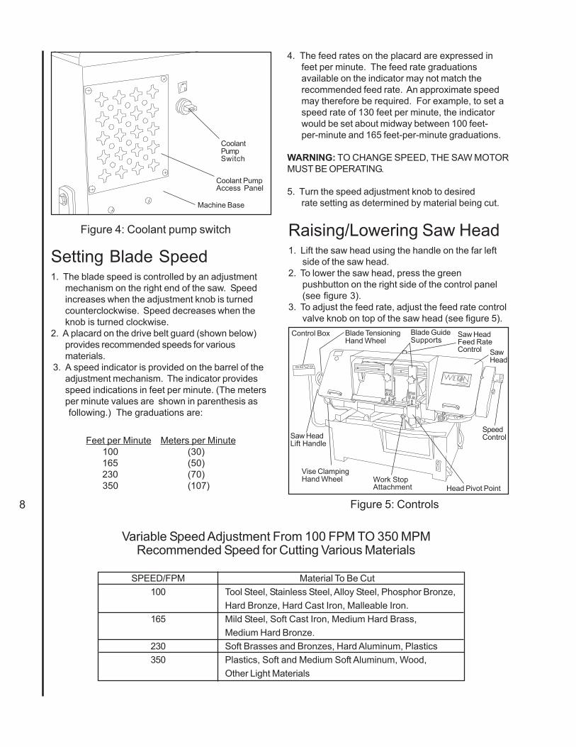
Figure 4: Coolant pump switch
CoolantPumpSwitch
Setting Blade Speed1. The blade speed is controlled by an adjustment
mechanism on the right end of the saw. Speedincreases when the adjustment knob is turnedcounterclockwise. Speed decreases when theknob is turned clockwise.
2. A placard on the drive belt guard (shown below)provides recommended speeds for variousmaterials.
3. A speed indicator is provided on the barrel of theadjustment mechanism. The indicator providesspeed indications in feet per minute. (The metersper minute values are shown in parenthesis as
following.) The graduations are:
Feet per Minute Meters per Minute 100 (30)
165 (50) 230 (70)
350 (107)
4. The feed rates on the placard are expressed infeet per minute. The feed rate graduationsavailable on the indicator may not match therecommended feed rate. An approximate speedmay therefore be required. For example, to set aspeed rate of 130 feet per minute, the indicatorwould be set about midway between 100 feet-per-minute and 165 feet-per-minute graduations.
WARNING: TO CHANGE SPEED, THE SAW MOTORMUST BE OPERATING.
5. Turn the speed adjustment knob to desiredrate setting as determined by material being cut.
Raising/Lowering Saw Head1. Lift the saw head using the handle on the far left
side of the saw head.2. To lower the saw head, press the green
pushbutton on the right side of the control panel(see figure 3).
3. To adjust the feed rate, adjust the feed rate controlvalve knob on top of the saw head (see figure 5).
Figure 5: Controls
Saw HeadLift Handle
Control Box Blade TensioningHand Wheel
Vise ClampingHand Wheel
Blade GuideSupports
Head Pivot PointWork StopAttachment
Saw HeadFeed RateControl
SpeedControl
SawHead
Coolant PumpAccess Panel
Machine Base
Variable Speed Adjustment From 100 FPM TO 350 MPMRecommended Speed for Cutting Various Materials
SPEED/FPM Material To Be Cut100 Tool Steel, Stainless Steel, Alloy Steel, Phosphor Bronze,
Hard Bronze, Hard Cast Iron, Malleable Iron.165 Mild Steel, Soft Cast Iron, Medium Hard Brass,
Medium Hard Bronze.230 Soft Brasses and Bronzes, Hard Aluminum, Plastics350 Plastics, Soft and Medium Soft Aluminum, Wood,
Other Light Materials

9
4. To lower the saw head with power off, pull and turnthe red knob (manual override) on the electro-magnetic valve (see figure 6).
Figure 6: Lowering head with poweroff
Electro-MagneticValve
RedReliefButton
Controlling the Cut:Hydraulic Feed ControlThe weight of the saw arm provides all the forceneeded to move the saw blade through the workpiece.In fact, if the full weight of the arm is allowed to makethe cut, rapid blade wear and poor cutting accuracywill result. A hydraulic feed control is provided thatgives the operator a means to control the speed andefficiency of cutting.
The hydraulic cylinder is attached between thesaw base and the saw head. The hydraulic cylinderresists movement of the saw head in the downwarddirection. However, the hydraulic cylinder offers noresistance when the saw head is raised upward.
The amount of downward force can be controlledby using the feed rate control valve. When the valve isopened slightly, the saw head will move downward.The further the valve is opened, the faster the sawhead will move downward.
The feed control is adjusted by the operator untilthe saw is operating efficiently. This is usuallydetermined by observing the chip formation. (SeeEvaluating Blade Efficiency for more information oncutting efficiency.)
Evaluating Cutting EfficiencyIs the blade cutting efficiently? The best way todetermine this is to observe the chips formed by thecutting blade.
If the chip formation is powdery, then the feed rateis much too light, or the blade is dull.
If the chips formed are curled, but colored — thatis, either blue or straw-colored from heat generatedduring the cut — then the feed rate is too high.
If the chips are slightly curled and are not coloredby heat — the blade is sufficiently sharp and iscutting at its most efficient rate.
Blade SelectionThe cut-off saw is provided with a saw blade that isadequate for a variety of cut-off jobs on a variety ofcommon materials. A 4/6 vari tooth bi-metal blade(5674011) and a 6/10 vari tooth bi-metal blade(5674021) are available from JET.
See Setting Blade Speed for the speeds recom-mended for various materials. These selections, whileappropriate for many shop cutting needs, do notencompass the wide variety of blades of specialconfiguration (tooth pitch and set) and special alloysfor cutting unusual or exotic materials.
A coarse blade could be used for a solid steel barbut a finer tooth blade would be used on a thin-walltube. In general, the blade choice is determined bythe thickness of the material; the thinner the material,the finer the tooth pitch.
A minimum of three teeth should be on the workpiece at all times for proper cutting. The blade andworkpiece can be damaged if the teeth are so farapart that they straddle the workpiece.
For very high production on cutting of specialmaterials, or to cut hard-to-cut materials such asstainless steel, tool steel, or titanium, you can askyour industrial distributor for more specific bladerecommendations. Also, the supplier who providesthe workpiece material should be prepared to provideyou with very specific instructions regarding the bestblade (and coolant or cutting fluid, if needed) for thematerial and shape supplied.
Blade Break-in ProceduresNew blades are very sharp and, therefore, have a
tooth geometry which is easily damaged if a carefulbreak-in procedure is not followed. Consult the blademanufacturer’s literature for break-in of specific bladeson specific materials. However, the following proce-dure will be adequate for break-in of JET-suppliedblades on lower alloy ferrous materials.1. Clamp a round section workpiece in the vise. The
workpiece should be 2 inches or larger in diam-eter.
2. Set the saw on low speed. Start the cut with avery light feed rate.
3. When the saw has completed 1/3 of the cut,increase the feed rate slightly and allow the saw tocomplete the cut.
4. Keep the same hydraulic cylinder setting andbegin a second cut on the same or similarworkpiece.

10
5. When the blade has completed about 1/3 of thecut, increase the feed rate. Watch the chipformation until cutting is at its most efficient rateand allow the saw to complete the cut (seeEvaluating Blade Efficiency). The blade is nowconsidered ready for regular service.
Work Set-upSetting Head Angle1. Move locking lever to the left to unlock swivel-head
(refer to Fgure 7).2. Move swivel-head to left until pointer is set on
desired angle (refer to Figure 8).3. Move locking lever right to lock worktable.
Locking Lever(Move right to loosen)
Angle Scale
Work TablePointer
Move table left to set angle
Figure 7: Quick-Acting Swivel-Head Lock
Figure 8: Locking Work Table
Work Table
Move table to selected angle
Securing Workpiece1. Set work table to desired angle. Lock in place
with locking handle.2. Place work piece against fixed jaw (refer to Figure
9).
3. Loosen hex post to free moveable jaw. Positionthe moveable jaw so it is parallel to and in contactwith the work piece.
4. Using the clamping hand wheel on the worktable,tighten the moveable jaw against the work piece.Then tighten the hex post on the moveable jaw.
Figure 9: Securing the Workpiece
Vise Jaw(Fixed)
HexPost
Vise Jaw(Moveable)
Work Table
Adjusting the Vise for AngleCuts (see figure 9)
1. Loosen the angle locking screw and the pivotscrew on the left vise jaw.
2. Turn the locking handle on the round, angle-settingblock counterclockwise to unlock the block. Slidethe block until the pointer on the block is alignedwith desired angle (see figure 9). Tighten thelocking handle to set the angle.
3. Set the workpiece in the vise. Put the front end ofthe workpiece against the corner of the right visejaw. Put the rear end of the workpiece against theangle-setting block.
4. Turn clamping hand wheel clockwise until the leftvise jaw is parallel with the workpiece. Tighten thepivot screw and angle locking screw on the leftvise jaw. Clamp the workpiece in position.
5. After completing the cut, turn the clamping handwheel counterclockwise and slide the left jawaway from the workpiece.
Move leftto lock

11
Installation and Adjustment ofWork Stop
The work stop is used to set up the saw formaking multiple cuts of the same length (see figure10). Install and adjust the work stop as follows:
1. Insert the end of the stop rod in the hole in thefront right side of the work table.
2. Tighten the Wing-screw to secure the rod inplace.
3. Install the stop post in the channel on the back ofthe stop L-bracket. Install the locking lever in thethreaded hole in the stop post. Snug-up thelocking lever.
4. Install the locking knob in the hole in the side ofthe stop L-bracket.
5. Slide the assembled stop L-bracket onto the stoprod. Position the stop post against the work pieceand tighten the knob in the stop L-bracket. Thestop post can be moved left or right as required toplace the stop post against the work piece.
Figure 10: Work stop
Stop Rod
Knob
Stop Post
Locking Lever
"Wing" Screw
Stop L-Bracket
Starting the SawWARNING: NEVER OPERATE THE SAW WITHOUTBLADE COVERS IN PLACE AND SECURED.
CAUTION: MAKE SURE THE BLADE IS NOT INCONTACT WITH THE WORKPIECE WHEN THEMOTOR IS STARTED. DO NOT DROP THE SAWHEAD ON THE WORKPIECE OR FORCE THE SAWBLADE THROUGH THE WORKPIECE.
1. Raise the saw head. With the saw motor off, pullthe red release button on the electro-magneticvalve and check the rate at which the saw headlowers.
2. Raise the saw head. Push in red release button.3. Clamp the workpiece in the vise. (See figure 11 for
examples of workpieces in the vise.)4. Be sure the blade is not in contact with the
workpiece when the motor is started.
5. Start the motor and allow the saw to come up tospeed.
6. Slowly set the saw down onto the workpiece.Adjust cutting speed with the feed rate controlvalve.
7. DO NOT DROP THE SAW HEAD OR FORCETHE CUT. Let the weight of the saw head providethe cutting force.
8. The saw will automatically shut off at the end ofthe cut.
Figure 11: Placing workpieces in the vise
f f
f
f
f
Flats/strips
Channels Angles
Squares/rectangles
I-Beams
Hexagonals Tees
Knock offsharp edgehere withfile
Rounds
Knock offsharp edgehere withfile
Coolant FlowCAUTION: THE COOLANT PUMP MUST BE SUB-MERGED BEFORE OPERATING TO PREVENTDAMAGE TO THE PUMP.
1. The blade guides are fitted with coolant fittings.Coolant is provided to the fittings through intercon-necting tubing. The coolant is dispensed directlyonto the saw blade.
2. Adjust the coolant flow valves on the top, rear ofthe saw head as required to provide the desiredflow. The flow should be no more than the bladecan draw into the workpiece by movement of theblade.
3. The coolant flow can be stopped in two ways: 1) By using the coolant pump switch on the electrical equipment box, or 2) By closing the coolant flow valves on the top, rear of the saw head.

12
Coolant Mixture and QuantityThe general purpose coolant is a mixture of watersoluble oil and water. Mix one part of soluble oil(TRIM SOL) to ten parts of water (one quart oil, tenquarts of water). The eleven quarts of coolant is theamount required for the coolant pump to operateproperly.
There are numerous coolants on the market thatare formulated for special applications. Consult yourlocal distributor for details in the event you have a longrange production task, or are required to cut some ofthe more exotic materials.
AdjustmentsThe efficient operation of the cut-off saw is depen-
dent upon the condition of the saw blade. If theperformance of the saw begins to deteriorate, the firstitem that you should check is the blade.
If a new blade does not restore the machine’scutting accuracy and quality, refer to the Trouble-shooting section (or the blade manufacturer's guide)for conditions to consider and adjustments that can bemade to increase the life of the blade.
To change the blade, refer to Changing Blades inthe Maintenance section. To adjust the blade track-ing, refer to the following procedures.
Blade Tracking AdjustmentBlade tracking has been tested at the factory. Adjust-ment is rarely required when the blade is usedproperly or if the blade is correctly welded. (Seefigure 12 for location of blade tracking adjustmentscrews.)
Factory or Field Procedure
1. Raise the saw head enough to allow the sawmotor to operate.
2. Loosen four knobs securing the blade cover. Liftthe cover and swing it backward.
3. Remove the blade guard mounted on the left bladeguide support.
4. Remove both blade guide bearing brackets.NOTE: Maintain proper tension at all times using the
blade tensioning mechanism.5. Loosen the center locking screws in all three hex
adjustment screws on the blade tensioningmechanism (see figure 12).
CAUTION: WHILE PERFORMING THE FOLLOW-ING, KEEP THE BLADE FROM RUBBING EXCES-SIVELY ON THE SHOULDER OF THE WHEEL.EXCESSIVE RUBBING WILL DAMAGE THE WHEELAND/OR THE BLADE.
6. Start the saw. Slowly turn the single hex adjust-ment screw at the rear of the tracking mechanismto tilt the idler wheel. Do not turn either of theother two adjustment screws. Turn the adjust-ment screw until the blade is touching the shoul-der of the idler wheel.
NOTE: Turning the screw inward causes the blade tomove toward the shoulder of the wheel. Turning thescrew outward causes the blade to move away fromthe shoulder.7. Turn the single hex adjustment screw so the blade
starts to move away from the shoulder of thewheel — then immediately turn the single hexadjustment screw in the other direction so theblade stops, then moves slowly toward theshoulder.
WARNING: KEEP FINGERS CLEAR OF THEBLADE AND WHEEL TO AVOID INJURY.
8. Turn the single hex adjustment screw to stop themotion of the blade on the wheel as it gets closer
to the wheel shoulder. Put a 6-inch length ofpaper between the blade and the wheel as shownin figure 13. The paper should not be cut as itpasses between the wheel shoulder and blade.
9. Turn the single hex adjustment screw a smallamount. Repeat the insertion of the paper be-tween the wheel shoulder and the blade until thepaper is cut in two pieces.
NOTE: You may have to repeat the check with thepaper several times before the blade and the shouldercuts the paper into two pieces. Do not hurry theadjustment. Patience and accuracy here will pay offwith better, more accurate, quieter cutting and muchlonger machine and blade life.10. When the paper is cut, turn the hex adjustment
screw slightly in the counterclockwise direction.
Figure 12: Blade tracking and tensioning
Blade TrackingHex AdjustmentScrews
CenterLockingScrews
SingleAdjustmentScrew

13
This assures that the blade is not touching theshoulder of the wheel.
11. Shut off the saw.12. Hold the hex adjustment screws with a wrench
and tighten the center locking screws. Makesure the hex adjustment screws do not movewhile tightening the center screws.
13. Install the two blade guide bearing brackets.Position the guides so the bearings just touch theblade.
14. Install the left blade guard.15. Close the saw head cover. Tighten the four
knobs.
Figure 13: Checking blade-to-wheelclearance using paper strips
Put StripBetweenWheelandBlade
Blade Guide BearingAdjustmentProper adjustment of the blade guide bearings iscritical to efficient operation of the cut-off saw. Theblade guide bearings are adjusted at the Factory.They should rarely require adjustment. When adjust-ment is required, adjust immediately. Failure tomaintain proper blade adjustment may cause seriousblade damage or inaccurate cuts.
It is always better to try a new blade when cuttingperformance is poor. If performance remains poorafter changing the blade, make the necessaryadjustments.
If a new blade does not correct the problem, checkthe blade guides for proper spacing. For mostefficient operation and maximum accuracy, provide
0.001 inch clearance between the blade and theguide bearings. The bearings will still turn freely withthis clearance. If the clearance is incorrect, theblade may track off the drive wheel.
CAUTION: CHECK THE BLADE TO MAKE SURETHE WELDED SECTION IS THE SAME THICKNESSAS THE REST OF THE BLADE. IF THE BLADE ISTHICKER AT THE WELD, THE GUIDE BEARINGSMAY BE DAMAGED.
If required, adjust the guide bearings as follows:1. The inner guide bearing is mounted on a concen-
tric bushing and can not be adjusted.2. The outer guide bearing (closest to the operator) is
mounted on an eccentric bushing and can beadjusted.
3. Hold the bushing with a 3/4-inch wrench andloosen the center locking screw with an Allenwrench (see figure 14).
Figure 14: Adjustment of guide bearings
INCORRECT CORRECT
OuterRoller
InnerRoller
BladeLockingScrew
Figure 15: Blade -to-bearing orientation
Blade
EccentricBushing
Guide Bracket
Inner Roller
LockingScrew

14
4. Position the bearing by turning the bushing. Setthe clearance at approximately 0.001 inch. Theblade should be in a vertical position between thebearings (see figure 15).
5. Tighten the center locking screw with an Allenwrench while holding the eccentric bushing inposition with the 3/4-inch wrench.
6. Use the same procedure to adjust the other guidebearing.
7. When the adjustment is correct, the guidebearings should rotate freely with slight pressureof the finger (with the blade stopped).
8. Adjust blade-edge bearings so they just touchthe back edge of the blade (see figure 21).
Test Cutting to VerifyAdjustment AccuracyTest cuts can be used to determine whether or notyou have adjusted the blade accurately. Use 2-inchround bar stock to perform these test cuts, as follows:1. With the bar stock securely clamped in the vise,
make a cut through the bar stock. (See figure 16.)2. Mark the top of the bar stock.3. Move the bar stock about 1/4-inch past the blade
so you can begin a second cut.4. Rotate the bar stock 180 degrees so the mark you
made is now at the bottom of the cut.5. Make a cut through the bar stock.6. Use a micrometer to measure the thickness
variation of the disk you have cut from the barstock. Measure at the top and bottom of the disk.
Figure 16: Cutting a test disc
1. Clamp in vise and mark topof barstock here
2. Cut off a slice ofthe bar stock
3. Rotate stock in viseso mark is at bottom
4. Cut off a newslice from thestock
5. Measurehere...
New slice7. Differences betweenmeasurements at edgesof disc should be lessthan .003 inches perinch per side of stockdiameter6. ...measure
here
The saw blade can be considered correctly adjustedwhen the variation measure is no more than 0.012inch across the face of the disk.
If you do not have a piece of 2-inch bar stockavailable for a test cut, use a larger diameter testpiece rather than a smaller one. The maximumthickness variation on any test piece should be nomore than 0.003 inch, per side, per inch of stockdiameter.
Adjustment of the LimitSwitch1. The limit switch is provided to shut off the saw
motor when the workpiece is cut through.2. To set the limit switch, loosen the jam nut on the
limit switch stop (see figure15).3. Adjust the stop as required and retighten the jam
nut.
MaintenanceCleaning1. Clean off any preservative on machine surfaces.2. After cleaning, coat the machined surfaces of the
cut-off saw with a medium consistency machineoil. Repeat the oil coating process at least everysix months.
3. Clean up accumulated saw cuttings after use.Make sure the lead screw is kept free of sawcuttings and other material that would causedamage.
4. Clean the chip sludge from the coolant tank. Thefrequency should be determined by how often thesaw is used.
Jam Nut
AdjustmentScrew
SwitchRoller
LimitSwitch
Figure 15: Limit switch adjustment
15
LubricationLubricate the following components at the specifiedfrequencies and using the lubricants defined below:1. Ball bearings: the bearings are lubricated and
sealed—periodic lubrication is not required.2. Blade guide bearing: the bearings are lubricated
and sealed—lubrication is not required. Inspectperiodically.
3. Idler wheel bushing: the bearings are lubricatedand sealed—lubrication is not required. Inspectperiodically.
4. Lead screw bearing housing: lubricate with light oilmonthly (see exploded figure, page 22).
5. Lead screw: lubricate with light oil monthly (seeexploded figure, page 20).
6. Hydraulic cylinder pivot: lubricate with light oilevery 6 months (see exploded figure, page 22).
7. Blade tension screw: lubricate with grease every 6months (see exploded figure, page 25).
8. Blade brush bearing: lubricate with light oilmonthly (see exploded figure, page 25).
9. Gear box: check oil once a year.10. Change coolant on a frequency appropriate to the
type of coolant being used. Oil based coolantscan sour. Refer to the coolant supplier’s instruc-tions for change frequency.
11. Coolant tank: clean every 6 months or as required.
Changing BladesWARNING: SHUT OFF ALL ELECTRICAL POWERTO THE MACHINE.
1. Loosen four knobs securing the blade cover. Liftthe cover and swing it backward.
2. Remove the blade guard mounted to the left bladeguide support.
WARNING: ALWAYS WEAR LEATHER GLOVESWHEN HANDLING SAW BLADE TO AVOID INJURYFROM THE SAW TEETH.
3. Turn the blade tensioning hand wheel clockwise torelieve tension on the blade. Loosen the bladeenough to remove the blade from the idler anddrive wheels. Remove the blade from between theblade guides.
4. Install the new blade between the blade guidebearings and the carbide blade guides. Install theblade over the drive and idler wheels.
5. Turn the blade tensioning hand wheel counter-clockwise to tighten the blade. Tighten the bladeuntil the blade tension indicator reads 2000 lbs.
6. Operate the saw at low speed and observe thetracking of the blade. If tracking needs to beadjusted, refer to Blade Tracking Adjustment.
7. Adjust the bearings on the upper edge of the bladeuntil they just contact the blade (see figure 21).
8. Check the guide bearings and the carbide guidesto make sure they are just contacting the sides ofthe blade.
9. Install the left blade guard making sure there isample clearance with the blade.
10. Make a test cut to make sure the blade tracksproperly during operation. Adjust tracking asrequired (see Blade Tracking Adjustment).
Changing the Drive Belt1. Disconnect the electrical power source from the
cut-off saw to prevent any possibility of accidentalmotor start-up.
2. Set the arm at the full horizontal position.3. Remove the knob on the drive belt cover. Remove
the drive belt cover to expose the V-belt andpulleys.
4. Remove two screws, nuts, and washers from backof saw head support. Push on the motor supportbracket to pivot the motor upward to loosen thetension on the belt.
5. Remove the worn belt.6. Put the replacement belt in the pulleys. Allow the
motor to pivot downward.7. Install the two screws, nuts, and washers in back
of saw head support and through the motorsupport bracket.
8. Install the drive belt cover. Install and tighten theknob on the drive belt cover.
Replacing the Drive Motor1. Disconnect the motor from all electrical power.
Unplug the motor if it is plugged into a socket.Shut off the power to the branch and remove theconnection to the junction box if the motor is hardwired to the branch.
2. Remove the drive belt from the drive motor pulley(see Changing the Drive Belt).
3. Remove motor pulley.4. Open the motor junction box and disconnect the
power cord wires from their terminals.5. Remove the nuts, washers and bolts that secure
the motor to the mounting plate.6. Installation of a new motor is a reversal of the
above steps.
Adjusting theCounterbalance SpringThe counterbalance spring is located at the right, rearof the saw head. The counterbalance spring is usedto adjust the amount of down force the saw head puts

16
on the workpiece when the feed rate control valve isfully open.1. Raise the saw arm to its full upright position and lock it in position (refer to Figure 18).
2. To adjust the tension on the spring, loosen thetwo nuts on the threaded rod of the spring pivotpost. Adjust the tension as required.
3. Tighten the two nuts against the pivot post.4. The saw can now be returned to service.
Replacing the Drive Wheel1. Remove the blade (see Changing Blades).2. Remove the screw, spring washer, and washer
from the speed reducer shaft.3. Pull the wheel from the speed reducer shaft.
Remove the drive key from the speed reducershaft.
4. Inspection: Examine drive edge and shoulder ofthe wheel for damage. Replace the wheel ifdamaged.
5. Install the key in the keyway in the speed reducershaft. Align the keyway in the wheel with the keyin the speed reducer shaft. Reinstall the wheel onthe speed reducer shaft.
6. Install the screw, spring washer and washer in theend of the speed reducer shaft.
7. Install the blade (see Changing Blades).
Replacing Idler Wheel orIdler Bearing1. Remove the saw blade (see Changing Blades).2. Remove the screw, spring washer, and washer
from the idler shaft.3. Remove the idler wheel. Remove the bearing from
the idler wheel.4. Inspection: Examine the drive edge and shoulder
of the idler wheel for damage. Replace the wheelif damaged.
5. Inspect bearings for damage and smooth opera-tion, Replace if faulty.
6. Install the bearing in the idler wheel. Install theidler wheel on the idler shaft.
7. Install the screw, spring washer and washer in theidler shaft.
8. Install the blade (see Changing blades).
Adjusting the Blade GuidesThe cut-off saw has adjustable blade guide supports(see figure 19). The blade guide supports allow you toset the blade guides for varying widths of workpieces.To make accurate cuts and prolong blade life, theblade guide supports should be set to just clear theworkpiece to be cut.
1. Loosen the knob on the blade guide support andslide the guide left or right as required. Repeat forthe other blade guide.
2. Set the blade guide supports as required toaccommodate the width/diameter of theworkpiece. The blade guides should be positionedso the guides do not contact the workpiece as thesaw head moves downward through the workpiece.
Replacement of CarbideBlade Guide (see figure 20)
Figure 19: Blade guide supports
BladeGuideSupports
Concentric Bushing
EccentricBushing
Blade Guide Bearings
Cap Screw(Typical)
CarbideGuides (2)
Cap Screw(Typical)
Figure 20: Carbide blade guidesand guide bearings
Figure 18: Counterblance SpringAdjustment
45¢X 40¢X35¢X
35 ¢X30¢X
25¢X
CounterblanceSpring
Hex Nut (2)(to adjusttension)

17
1. Remove the cap screw and remove the carbideguide. Discard the carbide guide.
2. Install the replacement carbide guide on the guidebearing support. Install the cap screw. Set the
guide so it just contacts the side of the saw blade.3. Using a machinist's square, check squareness of
the blade to the table.
Replacement of GuideBearings (see figure 20)
1. Remove the cap screw from the bearing beingreplaced. Separate the bushing and cap screwfrom the bearing. Discard the bearing.
NOTE: There is a light press fit between the bearingand the bushing.2. Install bushing in replacement bearing. Install cap
screw through bushing and into guide support.3. If the bearing being replaced is on an eccentric
bushing, install the bearing on the operator side ofthe blade.
4. Turn the eccentric bushing in the guide supportuntil the bearing contacts the blade.
Replacement of Blade EdgeBearings1. Remove the capscrew from the blade edge bearing
being replaced and discard the bearing. Becareful not to lose the spring washer that sepa-rates the bearing from the floating block (see figure21).
2. Insert the capscrew into the new bearing. Replacethe spring washer onto the capscrew and re-installinto the floating block.
3. If re-adjustment is necessary, loosen the pivotcapscrew and move the floating block so that theblade edge is close to the guide support, butcannot touch the bottom surface of it when thesawblade is cutting a workpiece.
Guide Support
Cap Screw
Blade EdgeBearing
Figure 21: Blade edge bearing replacement
AdjustmentCap Screw
Floating Block
Replacement of the WireBrush1. Loosen four knobs securing the blade cover. Lift
the cover and swing it backward.2. Remove the attaching screw, spring washer and
washer. Remove and discard the brush (seefigure 22).
3. Install replacement brush and secure with screw,spring washer and washer.
4. Close the blade cover and secure with four knobs.
Figure 22: Wire brush
Wire Brush
Screw and Washers
Machine SetupThe saw delivered to you has been adjusted at thefactory. A number of test pieces have been cut usingthe saw to verify the accuracy of cutting. Therefore,the only setup operations required before releasingthe saw for service are spotting the saw and estab-lishing the electrical connections to the motor.
Uncrating and SpottingSpot the saw where it makes the most sense for theoperations you will probably be doing. If you aregoing to be doing cut-off work on very long pieces ofstock, allow plenty of room for the stock, and theinfeed and outfeed supports. Remove the saw fromthe shipping skid and discard any hold-down devicesthat were used to secure the saw to the skid.

18
ElectricalObserve the following when connecting to the power source. (Refer to the wiring diagrams in Figures 23 - 26.)
WARNING: JET RECOMMENDS THAT ANY HARD WIRING OF THE SAW TO A BRANCH, OR ANY CHANGEOF VOLTAGE SUPPLIED TO THE MOTOR BE PERFORMED BY A LICENSED ELECTRICIAN.
1. Make sure the saw is disconnected from the power source, or that the fuses have been removed or breakerstripped in the circuit in which the saw will be connected. Make sure you put a warning placard on the fuse orcircuit breaker to prevent accidental electrical shock.
2. If you are installing the motor power cord into a receptacle, make sure to use the appropriate plug.3. If you are using hard-wired connections to a junction box, connect the wires in the box, and close the box.4. Install the fuses or reset the breaker.5. The saw is now ready for service.
Figure 23: Model J-7020M cut-off saw wiring diagram

19Figure 25: Model 7040M cut-off saw wiring diagram
Figure 26: Connection diagram for 3ph motor
220V - To reverse motor rotation hook terminal 6 to 1.
115V - To reverse motor rotation switch terminal 5 and 6.
Figure 24: Connection diagram for 1ph motor

20
TroubleshootingFault
Excessive bladebreakage
Premature bladedulling
Bad cuts(out-of-square)
Bad cuts (rough)
Probable cause
1. Material loose in vise.2. Incorrect speed or feed.
3. Teeth too coarse for material.
4. Incorrect blade tension.
5. Saw blade is in contact withworkpiece before the saw isstarted.
6. Blade rubs on the wheel flange.7. Misaligned guides.8. Cracking at weld.
1. Blade teeth too coarse.2. Blade speed too high.3. Inadequate feed pressure.4. Hard spots in workpiece or scale
on/in workpiece.
5. Work hardening of material(especially stainless steel).
6. Insufficient blade tension.7. Operating saw without pressure on
workpiece.
1. Workpiece not square with blade.
2. Feed pressure too fast.3. Guide bearings not adjusted
properly.4. Inadequate blade tension.5. Span between the two blade
guides too wide.6. Dull blade.7. Incorrect blade speed.
8. Blade guide assembly is loose.9. Blade guide bearing assembly
loose.10. Blade track too far away from
wheel flanges.11. Guide bearing worn.
1. Blade speed too high for feedpressure.
2. Blade is too coarse.
Suggested remedy
1. Clamp work securely.2. Check Machinist’s Handbook for
speed/feed appropriate for thematerial being cut.
3. Check Machinist’s Handbook forrecommended blade type.
4. Adjust blade tension to the pointwhere the blade just does not slipon the wheel.
5. Start the motor before placing thesaw on the workpiece.
6. Adjust blade tracking.7. Adjust guides.8. Longer annealing cycle.
1. Use a finer tooth blade.2. Try a lower blade speed.3. Decrease spring tension.4. Increase feed pressure (hard
spots). Reduce speed, increasefeed pressure (scale).
5. Increase feed pressure by reduc-ing spring tension.
6. Increase tension to proper level.7. Do not run blade at idle in/on
material.
1. Adjust vise so it is square with theblade. (Always clamp work tightlyin vise.)
2. Decrease pressure.3. Adjust guide bearing clearance to
0.001 inch (0.002 inch maximum).4. Gradually increase blade tension.5. Move blade guide bar closer to
work.6. Replace blade.7. Check blade speed
(see Figure 3).8. Tighten blade guide assembly.9. Tighten blade guide bearing
assembly.10. Adjust blade tracking.
11. Replace worn bearing.
1. Reduce blade speed and feedpressure.
2. Replace with finer blade.
NOTE: Troubleshooting continued on next page

21
Blade is twisting
Unusual wear onside/back of blade
Teeth missing/rippedfrom blade
Motor running too hot
No coolant flow
Excessive speedreducer noise/vibration
1. Blade is binding in the cut.2. Blade tension too high.
1. Blade guides worn2. Blade guide bearings not adjusted.3. Blade guide bearing bracket is
loose.
1. Blade tooth pitch too coarse forworkpiece.
2. Feed too slow; feed too fast.
3. Workpiece vibrating.4. Gullets loading up with chips.
1. Blade tension too high.2. Drive belt tension too high.3. Blade too coarse for workpiece
(especially with tubular stock).4. Blade too fine for workpiece
(especially with heavier, softmaterial).
5. Speed reducer gears requirelubrication.
1. Pump motor is burned out.2. Screen/filter on pump is clogged.3. Impeller is loose.4. Coolant level too low.
1. V-belt is too tight.2. Countering spring not tensioned
properly.
1. Decrease feed pressure.2. Decrease tension on blade
1. Replace blade guides.2. Adjust blade guide bearings.
3. Tighten blade guide bearingbracket.
1. Use blade with finer tooth pitch.
2. Increase feed pressure and/orblade speed.
3. Clamp workpiece securely.4a. Use blade with a coarse tooth
pitch—reduce feed pressure.4b. Brush blade to remove chips.
1. Reduce tension on blade.2. Reduce tension on drive belt.3. Use blade with fine tooth pitch.
4. Use blade with coarse tooth pitch.
5. Check speed reducer.
1. Replace pump.2. Clean screen/filter.3. Tighten impeller.4. Add coolant to reservoir.
1. Reset V-belt tension.2. Increase spring tension.
Replacement PartsThis section provides exploded view illustrations that show the replacement parts for the 10-inch x 16-inch Cut-Off Saw. Also provided are parts listings that provide part number and description. The item numbers shown onthe illustration relate to the item number in the facing parts listing.
Order replacement parts from:WMH TOOL GROUP, Inc.427 New Sanford RoadLaVergne, Tennessee 30786Ph.: 800-274-6848
Identify the replacement part by the part number shown in the parts listing. Be sure to include the modelnumber and serial number of your machine when ordering replacement parts to assure that you will receive thecorrect part.

22
Exp
lode
d V
iew
- M
odel
J-7
020M
/J-7
040M
Mite
r Cut
-off
Saw
Bas
e

23
Parts List - Model J-7020M/J-7040M Miter Cut-off Saw Base
* Not shown in exploded view.
ITEM PARTNO. NO. DESCRIPTION QTY1 J-5507591 Base, Machine 11-1 5512197 Plug, Drain (3/8in, PT)2 5507592 Screw, Cap, 12 x 70 43 5507593 Nut, Hex, M12 44 Pump, Coolant 1
J-5712281 115/220V, 1 PhaseJ-5712921A 220/440V, 3 Phase
* 5512101 Filter Screen w/Screw 15 5507595 Screw, Slotted, M6 x 16 45-1 5507607 Flat Washer, M12 46 5507596 Fitting, Hose 17 5507597 Clamp, Hose 18 5712331 Hose 5/16 19 5507599 Gauge, Coolant 110 5507600 Bolt, Hex, M10 x 30 210-1 5507599-1 Washer, Cotton, M10 210-2 TS-1540071 Nut Hex M10 210-3 5507613 Flat Washer, M10 211 5712351 Bracket, Pump, Coolant 112 5507602 Cover, Panel 113 5507603 Screw, Pan Head, 12
1/4" x 3/8'14 J-5507604 Tray, Drip 115 5507605 Bolt, Hex, M8 x 16 215-1 5507637 Washer, Lock, M8 215-2 5507668 Flat Washer, M8 216 5507606 Bolt, Hex, M12 x 30 417 5507607 Washer, Flat, M12 418 5512701 Bolt, Hex M8 x 16 119 5507608 Washer, Flat 120 5507609 Bracket, Turning Slide 120-1 5516251 Screw, Set, M8 x 10 421 5507610 Bracket, Center Fixed 121-1 TS-1492031 Bolt, Hex, M12 x 35 321-2 5516256 Washer,Lock, M12 322 5507611 Bearing, Thrust 123 J-5507612 Slide, Turning, Right 123-1 5516251 Screw, Set, M8 x10 1224 5507613 Washer, Flat, M10 225 5507614 Screw, Cap, M10 x 40 325-1 5516255 Washer, Lock, M10 326 5507615 Screw, Cap, M6 x 20 227 5512702 Bolt, Hex 127-1 5507619 Nut, Hex, M10 128 5507616 Bracket 129 5507613 Washer, Flat, M10 230 5507614 Screw, Cap, M10 x 40 230-1 5516255 Washer, Lock, M10 331 5512705 Nut, Sliding 232 5507618 Screw, Cap, M6 x30 232-1 5516257 Washer, Lock, M6 233 5512706 Bracket 134 5507619 Nut, Hex, M10 135 5507620 Bolt, Hex, M10 x 25 136 5507621 Screw, Set, M8 x 16 237 5512707 Bracket, Mounting 138 TS-149105 Bolt, Hex, M10 x 35 238-1 5516255 Washer, Lock, M10 238-2 5507613 Flat Washer, M10 239 5713111 Knob, Lock 1
40 5712441 Handle, Lock 141 5712421 Work Stop Bracket 142 5712451 Stop, Work 143 5712431 Rod, Work Stop 144 J-5507628 Support 144-1 TS-1482061 Screw, Cap, (M6 x 30) 144-2 5516257 Washer, Lock, M6 144-3 5516253 Washer, M6 145 5507629 Screw, Set 146 5507630 Handle, Adjustable 247 5507631 Pin, Cylinder 148 5507632 C-Ring, S-20 149 5507633 C-Ring, S-25 250 J-5507634 Bed 150-1 TS-1491041 Bolt, Hex, M10 x 30 150-2 5507619 Nut, Hex, M10 151 5712471 Hand Wheel Assembly 151-1 TS-0051011 Screw, Set, 5/16" x 1/2" 152 5507636 Bolt, Hex, M8 x 30 252-1 5507668 Flat Washer, M8 253 5507637 Washer, Lock, M8 254 5712481 Lead Screw Bracket 155 5712511 Vice Lead Screw 155-1 Key, 5 x 5 x 20mm 156 5712521 Lead Screw Bracket 157 5712531 Nut, Acme 158 5712541 Acme Nut Button 159 5712551 Acme Nut Retainer 260 5712561 Screw Pn Hd PhlpsM5 x 8 170 5507646 Panel, Electrical, Access 171 Overload 1
5507542 115V, 1-Phase5713031 220V, 1-Phase5512660 220V, 3-Phase5712661 440V, 3-Phase
71A 5508409 Relay, 115/220V, NC 172 Motor Contactor 2
5713041 115/220V, 1 Phase5713001 220/440V, 3 Phase
73 5713051 Transformer,1PH/3PH 174 5713061 Strip, Terminal 175 5507651 Washer, Flat, M16 276 5512708 Handle 177 5712571 Bearing, Needle 278 5507653 Screw, Cap, M6 x 12 278-1 5516257 Washer, Lock, M6 279 5507654 Plate, Guide 180 5507655 Spring, Torsion 181 5712591 Shaft, Pivot 182 5507607 Washer, Flat, M12 283 5507658 Fitting, Brass 285 5507660 Bracket, Pivot 186 5507661 Nut, Hex, M12 187 5507607 Washer, Flat, M12 188 5507662 Bolt, Hex, M12 x 40 189 5507663 Shaft, Torsion Spring 190 5507664 C-Ring, S-22 191 5507665 Bolt, Cap, M8 x 25 191-1 5507637 Washer, Lock, M8 291-2 5507668 Flat Washer, M8 2
ITEM PARTNO. NO. DESCRIPTION QTY

24
Parts List - Model J-7020M/J-7040M Miter Cut-off Saw Base
* Not shown in exploded view.
ITEM PARTNO. NO. DESCRIPTION QTY92 5507666 Plate, Motor Tilt 192-1 TS-1490041 Bolt, Hex, M8 x 25 193 5507667 Plate, Limit Switch 194 5507668 Washer, Flat, M8 295 5507669 Bolt, Hex, M8 x 10 295-1 5507637 Washer, Lock, M8 296 TS-1482011 Bolt, Hex, M6 x 10 497 5712741 Switch, Limit 198 5507671 Plate 299 5507607 Washer, Flat, M12 2100 5512711 Screw, Cap, M12 x 50 2101 5711091 Nut, Hex, 1/2 1102 5507674 Bracket, Spring 1103 5512712 Screw, Cap, M8 x 30 2103-1 5507668 Flat Washer, M8 2103-2 5507637 Washer, Lock, M8 2104 5711091 Nut, Hex, 1/2 1105 5507675 C-Bolt, Adjustable 1106 5507676 Spring 1107 5507677 Vise, Left Jaw 1108 5512713 Bolt, Hex, M12 x 35 1109 5512714 Screw, Clamping 1110 5507678 Washer, Lock, M12 1111 5507679 Pin, Pivot 1112 5507680 Vise, Fixed Jaw 1113 5512715 Bolt, Hex, M12 x 40 1113-1 5507607 Flat Washer, M12 3114 5507678 Washer, Lock, M12 5115 5713231 Swivel Bushing 1115-1 C-Ring, S-32 1116 5507682 Screw, Cap 2117 5507683 Box, Stationary 1117-1 TS-1490021 Bolt, Hex, M8 x 16 4117-2 5507637 Washer, Lock, M8 4117-3 5507668 Flat Washer, M8 4118 5713271 Screw, Cap, 1/4 x 3/4 2119 J-5713261 Column, Control 1120 5713281 Swivel 1120-1 TS-0050021 Screw, Cap, 1/4" x 5/8" 1120-2 5519510 Nut, Hex, 1/4" 1121 5507686 Cylinder, Hydraulic 1122 5507687 Washer, Lock, M10 3123 5512718 Bolt, Hex, M10 x 30 3124 J-5507688 Plate, Hydraulic Mtg. 1125 5507689 Pin, Cotter 1126 J-5713291 Box, Control 1127 5713311 Panel, Control 1128 5713321 Screw,Slotted, 3/16 x 1/4 6129 5713331 Lamp, Electric Pwr on 1130 5713341 Switch, Start 1131 5713351 Switch, Stop 1132 5713361 Switch, Down 1133 5516855 Switch, Pump, Coolant 1134 Panel, Elect., Complete 1
5514613 3-Phase5514616 1-Phase
135 5713371 E-M Valve Complete 1263 Cover, Box 1
ITEM PARTNO. NO. DESCRIPTION QTY263-1 Screw, Pan Head, 4
3/16" x 1/4"264 Base, Box 1265 J-5521930 Sliding,Turn, Left 1265-1 Scale, Angle 1265-2 Screw, Cap, M10 x 25 1266 Strain Relief 1267 Ring, Rubber 1268 Ring, Rubber 1269 5519503 Fuse, 1A 3270 5519502 Bracket, Fuse 3271 Bushing, 9mm 1272 Bushing, 3mm 1273 5516856 Panel, Access 1 * 5512787 Kit, Piston/Seal 1 * 5713371A E-M Valve & Coil 1

25
Exp
lode
d V
iew
- M
odel
J-7
020M
/J-7
040M
Mite
r Cut
-off
Saw
Hea
d

26
Parts List - Model J-7020M/J-7040M Miter Cut-off Saw HeadITEM PARTNO. NO. DESCRIPTION QTY145 5713381 Screw, 1/4 x 3/8 2146 J-5507697 Cover, Blade Wheel 1146-1 5518109 Label, JET Logo 1146-2 5519511 Label, Blade Size 1146-3 5519513 Label, Glasses 1146-4 5519512 Label, Warning 1147 5713411 Guard, Wire Brush 1147-1 5519514 Label, Saw 1148 5713421 Handle 2149 5713431 Washer, 1/2" 1150 J-5713831 Wheel, Drive 1150-1 Bushing, 4mm 1151 Blade, Bi-Metal 1
5674011 4/6 Vari Tooth5674021 6/10 Vari Tooth
152 5713461 Hose 1152-1 5519515 Clamp, Hose 1153 5713471 Bolt, 3/8 x 1-1/4 4154 5713481 Washer, Spring, 3/8 4155 5713491 Bolt, 1/2 x 1-1/4 4156 5713511 Bolt, 5/16 x 1/2 2157 5713521 Screw, 1/4 x 5/8 4157-1 5713661 Washer, 1/4 4158 J-5507709 Box, Blade Wheel 1158-1 Label, ID 1158-2 5519672 Label, Tension 1158-3 5519696 Stopper, Arm 1158-4 5711091 Nut, Hex, 1/2" 1159 5713541 Seat, Support Bracket 1159-1 TS-0070051 Bolt, Hex, 1/2" x 2" 1159-2 5711091 Nut, Hex, 1/2" 1160 J-5507711 Gearbox Assembly 1160-1 5519675 Key, 7 x 7 x 40 1161 5513734 Key, 7 x 7 x 65 1162 J-5507713 Cover, Speed Change 1162-1 5510677 Label, Speed Chart 1162-2 5519676 Knob 1162-3 5714041 Washer, 3/8" 1163 5713581 Pulley, Gearbox 1164 5713591 Belt 1165 5713611 Pulley, Motor 1166 J-5507717 Plate, Speed Change 1166-1 Bolt, Hex, M8 x16 2166-2 5507637 Washer, Lock, M8 2166-3 5507668 Flat Washer, M8 1167 5507718 Plate, Motor Mount 1168 5713771 Washer, 5/16 2169 5713661 Washer, 1/4 1170 5713651 Washer Lock 1/4 2171 5713661 Washer, 1/4 2172 5714291 Valve, Relief 1173 5628371 Washer, Spring, 1/2 4174 5713691 Washer, Black, 5/16 4175 5713711 Screw, Cap, 3/8 x 1 2176 5713721 Screw, Cap, 5/16 x 5/8 4177 Motor 1
J-5713731M Model 7020, 1HP, 1PJ-5713732M Model 7040, 2HP, 3P
177-1 Label, Motor 15519682M Model 7020, 1HP, 1P
5519683M Model 7040, 2HP, 3P177-2 TS-1490081 Bolt, Hex, M8 x 45 4177-3 5507637 Washer, Lock, M8 4177-4 5507668 Washer, M8 8177-5 5516239 Nut, Hex, M8 4178 5713741 Bolt, 1/2 x 3/4 1180 5513733 Key, 7 x 7 x 40 1181 5713761 Washer, 1/2" I.D. 1182 5713771 Washer, 5/16 2183 5713671 Screw, Slotted, 1/4 x 3/8 6184 5713781 Screw, Cap, M16 x 30 3185 5713791 Bolt, 1/2 x 3/4 1186 5713811 Washer, 1/2 1187 BB-6205Z Bearing 6205Z 2188 J-5713441 Wheel, Idler 1189 J-5713841 Guard, Blade 1189-1 TS-1490021 Bolt, Hex, M8 x16 1189-2 5507637 Washer, Lock, M8 1189-3 5507668 Washer, M8 1190 5713851 Left Blade Guide Brkt. 1190A 5713851A Right Blade Guide Brkt. 1190-1 Screw, Cap, 1/2" x 3/8" 4190-2 5628371 Washer, Lock, 1/2" 4190-3 5507607 Washer, 1/2" 4190-4 5519684 Tube, Copper 2190-5 TS-0270051 Srcrew, Set, 5/16" x 1/2" 6191 5717138 Assy., Eccentric Shaft 2191A 5717142 Assy., Center Shaft 2192 5713871 Guide, Blade, Tun. Carb. 4192-1 5713661 Washer, 1/4" 8192-2 5713651 Washer, Lock, 1/4" 4192-3 5519508 Screw, Cap, 1/4" x 1" 4193 5713881 Block, Elevating 2194 5713891 Block, Active 2195 5713911 Screw, Cap, 1/4 x 5/16 2196 5632831 Bearing, 608ZZ 4197 5713931 Washer, Spring, 5/16 4198 5713941 Screw, Cap, 5/16 x1-3/4 4199 5713951 Washer,Lock,Black,5/16 4200 J-5713961 Guide Support 2200-1 5518423 Label, Blade Orientation 2201 5713971 Scale, Angle 1202 5713981 Screw, Flat, M5 x 0.8 4203 5713991 Guide Support Mount 1204 J-5714011 Left Bracket support 1204-1 5712561 Screw, Pan Head, M5 x 8 4204-2 5519694 Clamp, Rubber 4205 5714021 Screw, 1/2 x 1 4205-1 5507607 Washer, 1/2" 2206 5714031 Knob 2207 5714041 Washer, 3/8 2208 5714051 Block, Locking 2209 5714061 Screw, 5/16 x 1/2 4210 J-5714071 Right Bracket support 1211 5714161 Bolt, 1/4 x 1/2 1212 5713651 Washer, Spring, 1/4 1213 5714111 Brush, Wire 1214 5714121 Seat, Steel Brush 1215 5713771 Washer, 5/16 2216 5714141 Clamp, Hose 2
ITEM PARTNO. NO. DESCRIPTION QTY
A

27
Parts List - Model J-7020M/J-7040M Miter Cut-off Saw HeadITEM PARTNO. NO. DESCRIPTION QTY217 5713651 Washer, Spring, 1/4 4218 5714161 Bolt, 1/4 x 1/2 4219 5628371 Washer, Spring, 1/2 4220 5714181 Gib 2221 5714191 Screw, Cap, 1/2 x 3/4 1222 5714211 Screw, Cap, M8 x 20 4222-1 5507668 Washer, M8 4224 5714221 Knob 4225 5714231 Nozzle, Flexible 1225-1 5507607 Clamp, Hose 4226 5714241 Shaft, Blade Wheel 1226-1 5519691 Scale, Tension 1226-2 5519690 Screw, Pan Head, 2
M6 x 12227 5714251 Threaded Nut 1228 5714261 Screw, Set, 5/16 x 1/2 1229 5714271 Bracket, Slide 1230 5714281 Washer 1231 5507788 Shaft, Support 1231-1 C-Ring, S-19 1232 J-5507785 Bracket, Motor Mount 1232-1 TS-1492021 Bolt, Hex, M12 x 30 2233 5507790 Bearing (51104NJK) 1234 5507791 Washer 1235 5508005 Nut, Hex 1238 5714331 Handle, Blade Cover 1239 5711091 Nut, Hex, 1/2 1240 5714351 Washer, 3/4 1241 5714361 Washer, Special Spring 13242 5714371 Wheel, Hand 1243 J-5714381 Bracket, Slide 1244 5714391 Shaft, Tension 1244-1 5519692 Nut, Hex 1244-2 5519693 Screw, Set, M6 x8 1245 5714411 Key, Square, 5MM 1246 5714421 Bolt, 3/8 x 2-1/2 3246-1 5713481 Washer, Lock, M10 3247 J-5714431 Seat, Oil Pressure 1247-1 TS-1490021 Bolt, Hex, M8 x 16 2247-2 5507637 Washer, Lock, M8 2247-3 5507668 Washer, M8 2248 J-5714441 Plate, Cover 1249 5714451 Screw, Slotted, 5/16x5/8 2250 5714461 Panel, Control 1251 5714471 Screw, Slotted, 1/4x3/8 2252 5713941 Screw, Cap, 5/16x1-3/4 4253 5712881 Washer, Lock, 1/2 4254 5517141 Bushing, Eccentric 2255 5517140 Bushing, Center 2256 5713861 Bearing, Ball, 6201ZZ 8257 5713761 Washer, 1/2 4258 5519492 Rivet, 2mm 9259 TS-1525031 Screw, Set, M10 x 16 2260 5519679 Bracket 1260-1 5713381 Bolt, Hex, 1/4" x 3/8" 2260-2 5713651 Washer, Lock, 1/4" 2260-3 5713661 Washer, 1/4" 2261 5519678 Rod 1
ITEM PARTNO. NO. DESCRIPTION QTY261-1 5714041 Washer, 3/8" 1261-2 5713081 Nut, Hex, 3/8" 1262 5714311 Connection, Head 1

WMH TOOL GROUP, Inc.427 New Sanford Road
LaVergne, Tennessee 30786Ph.: 800-274-6848
www.wmhtoolgroup.com