Operating instructions 600T EN Series Safety Pressure Transmitters Models 6X1SD … ·...
56
600T EN Series Safety Pressure Transmitters Models 6X1SD-SE-SH-SG-SA Models 6X1SS Operating instructions
Transcript of Operating instructions 600T EN Series Safety Pressure Transmitters Models 6X1SD … ·...

- 1 -
600T EN Series
Safety Pressure TransmittersModels 6X1SD-SE-SH-SG-SAModels 6X1SS
Operating instructions

- 2 -
Health and SafetyTo ensure that our products are safe and without risk to health, the following points must be noted:
1. The relevant sections of these instructions must be read carefully before proceeding.
2. Warning labels on containers and packages must be observed.
3. Installation, operation, maintenance and servicing must only be carried out by suitably trained personnel and in accordance with theinformation given.
4. Normal safety precautions must be taken to avoid the possibility of an accident occurring when operating in conditions of highpressure and/or temperature.
5. Chemicals must be stored away from heat, protected from temperature extremes and powders kept dry. Normal safe handlingprocedures must be used.
6. When disposing of chemicals ensure that no two chemicals are mixed.
Safety advice concerning the use of the equipment described in this manual or any relevant hazard data sheets (where applicable) maybe obtained from the Company address on the back cover, together with servicing and spares information.
The Company
ABB Automation is an established world force in the design and manufactureof instrumentation for industrial process control, flow measurement, gas andliquid analysis and environmental applications.
As a part of ABB, a world leader in process automation technology, we offercustomers application expertise, service and support worldwide.
We are committed to teamwork, high quality manufacturing, advancedtechnology and unrivalled service and support.
The quality, accuracy and performance of the Company’s products result fromover 100 years experience, combined with a continuous program of innovativedesign and development to incorporate the latest technology.
The NAMAS Calibration Laboratory No. 0255(B) is just one of the ten flowcalibration plants operated by the Company, and is indicative of ABBAutomation’s dedication to quality and accuracy.
Use of Instructions
Warning .An instruction that draws attention to the risk of injury ordeath.
Caution.An instruction that draws attention to the risk of damageto the product, process or surroundings.
RE
GIS T E R E D F
IRM
BS EN ISO 9001
St Neots, U.K. – Cert. No. Q5907Stonehouse, U.K. – Cert. No. FM 21106
Stonehouse, U.K. – Cert. No. 0255
UNI EN 29001 (ISO 9001)
Lenno, Italy – Cert. No. 9/90A
Although Warning hazards are related to personal injury, and Caution hazards are associated with equipment or propertydamage, it must be understood that operation of damaged equipment could, under certain operational conditions, result indegraded process system performance leading to personal injury or death. Therefore, comply fully with all Warning andCaution notices.
Information in this manual is intended only to assist our customers in the efficient operation of our equipment. Use of this manualfor any other purpose is specifically prohibited and its contents are not to be reproduced in full or part without prior approvalof Technical Communications Department, ABB Automation.
Note.Clarification of an instruction or additional information.
Information.Further reference for more detailed information ortechnical details.
ABB AUTOMATION
Year 2000 compliance600T EN Series products have no impact due to year 2000, operating as follows:
• the Year 2000 date format will be "00";
• the date is used only as caption, no calculation are done on date in the products, comparisons on dates are not supported in theproducts;
• the products continue to work in the correct manner;
• the product send to the connected systems the correct information;
• if the products receive an input that it is not compatible with Year 2000 there are not damages or faults to the products themselves.

- 3 -
Section Page
INTRODUCTION............................................................ 3TRANSPORT, STORAGE, HANDLING ANDPRODUCT IDENTIFICATION ........................................ 4SAFETY PHILOSOPHY, MANAGEMENT OFFUNCTIONAL SAFETY AND INFORMATIONREQUIREMENTS .......................................................... 5LIFE-CYCLE ACTIVITIES .............................................. 6FAULTS OUTSIDE THE FUNCTIONAL SAFETY ......... 8PRINCIPLE OF OPERATION ........................................ 9INSTALLATION............................................................ 12ELECTRICAL CONNECTIONS ................................... 13ELECTRICAL REQUIREMENTS ................................ 16COMMISSIONING AND CONFIGURATIONISSUES ........................................................................ 17CALIBRATION ............................................................. 18PRE-STARTUP ACCEPTANCE TEST,PROOF TESTS ............................................................ 20DISMANTLING AND REASSEMBLY .......................... 21SIMPLE FAULT FINDING ............................................ 22RETURNING FORM .................................................... 23ADDENDUM FOR "METERS" OPTION OFTHE TRANSMITTERS ................................................. 24ADDENDUM FOR COMETER OR INDICATORWITH HART PROGRAMMING CAPABILITY .............. 27ADDENDUM FOR PV-SCALING OPERATION ........... 32ADDENDUM FOR "SURGE PROTECTOR" OPTIONOF THE TRANSMITTERS ........................................... 33ADDENDUM FOR DIFFERENTIAL PRESSURETRANSMITTERS : SELECTABLE OUTPUTFUNCTIONS ................................................................ 37ADDENDUM FOR FLANGE-MOUNTEDTRANSMITTERS ......................................................... 43ADDENDUM FOR "EX SAFETY" ASPECTSAND "IP" PROTECTION (EUROPE) ........................... 49
CONTENTS INTRODUCTION
The 600T series is a modular range of field mounted, micro-processor based electronic transmitters, using a uniqueinductive sensing element. Accurate and reliablemeasurement of differential pressure, gauge and absolutepressure, flow and liquid level is provided, in the even mostdifficult and hazardous industrial environments.
Now a Safety pressure Transmitter is included in the 600TSeries, with its analog output signal plus HART digitalcommunication.The HART digital protocol allows remote re-ranging,calibration and diagnostics, without any interference with thestandard 4-20 mA analog output signal.This operating instructions manual describes the Safetyversion of the 600T Series transmitters and specify allinformation necessary to safely connect the Safety 600Tpressure transmitter in a Safety Instrumented System.It details also how the signals from the input field device shouldbe interpreted.
Refer to the shortened contents of this manual, here in thispage for addressing the section of your interest, and also to thesupplementary documentation for additional remarks.
Reference information on remote seals and configuration ofthe transmitter can be found in the following documents:
SS / S6 Rev. 6 Remote Seal Specification
IM / 691HT Rev. 1 Hand-Held Communicator
Online HELP SMARTVISION Configuration Program
IEC 61508 Functional Safety of e/e/pe Safety-related systems
ISA S84.01 Application of Safety Instrumented Systems forthe Process Industries
NE43 Standardization of the signal level for the breakdowninformation of digital transmitters
Other help ful or general information can be found in the ABBweb site, at www.abb.com

- 4 -
Important - The instrument serial number must always be quoted when making enquiries.
PRODUCT IDENTIFICATIONThe instrument is identified by the data plates shown inFigure 1.The Nameplate (ref.A) provides information concerning thecode number, maximum working pressure, range and spanlimits , power supply and output signal. See code/specificationsheet for detailed information. This plate also shows thetransmitter serial number. Please refer to this number whenmaking enquiries .A dedicated label (ref. B) is welded as standard to the primaryunit, carrying specific details of the transducer (diaphragmmaterial, fill fluid, range limits and sensor serial number).A Safety Marking plate ( ref. C) is fitted when the transmitteris required to comply with hazardous area regulations, e.g.flameproof or intrinsic safety protection. Additional Tag plate(ref. D) provides the customer tag number and calibratedrange; this is screwed on the housing and can be removed tobe wired-on by the supplied stainless steel wire (as in thepicture).
Fig. 1 - Product identification
Ref. B
Primary Unit
NameplateRef. A
TRANSPORTAfter final calibration, the instrument is packed in a carton(Type 2 to ANSI/ASME N45.2.2-1978), intended to provideprotection from physical damage.
STORAGEThe instrument does not require any special treatment ifstored as despatched and within the specified ambientconditions level (Type 2 to ANSI/ASME N45.2.2-1978).There is no limit to the storage period, although the terms ofguarantee remain as agreed with the Company and as givenin the order acknowledgement.
HANDLINGThe instrument does not require any special precautionsduring handling although normal good practice should beobserved.
Ref. C
Ref. D
Ref. A
DIN TYPEHOUSING
BARREL TYPEHOUSING
SERIALNUMBER
URL
DIAPHRAGMMATERIAL
FILLFLUID
3rd and 4th numerals showthe year of construction
(Ex) - - X X - - - -
Ref. D

- 5 -
SAFETY PHILOSOPHY
The Safety 600T Pressure Transmitters are field devicesdesigned according the requirements of the standard IEC61508for the Safety Related Systems. Standard currently used focuson individual parts of all the safe instrumentation used toimplement a safety function. The IEC61508 definesrequirements related to all the system that normally comprisesinitiating devices, logic solver and final elements. It alsointroduces the concept of Safety lifecycle defining the sequenceof activities involved in the implementation of the safetyinstrumented system from conception throughdecommissioning. For a single component it is not correct todefine a SIL level. The term SIL (Safety Integrity Level) refersto the complete safety loop therefore the single device shall bedesigned in order to be suitable to achieve the desired SIL levelin the entire Safety Loop.
ApplicationThe Safety 600T Pressure Transmitters are intended to beapplied for safety relevant application in the process industry.They are suitable to be used in SIL2 applications. Specialattention has to be given to the separation of safety and non-safety relevant use.
Physical EnvironmentThe transmitter is designed for use in industrial fieldenvironments and must be operated within the specifiedenvironmental limits as indicated in the Transmitter DataSheet.
Role an ResponsibilitiesAll the people, departments and organisations involved in thelife-cycle phases which are responsible for carrying out andreviewing the applicable overall, E/E/PES (Electrical/Electronic/Programmable Electronic System) or software safety lifecyclephases of a Safety Instrumented System shall be identified. Allthose specified as responsible for management of functionalsafety activities shall be informed of the responsibilities assignedto them. All persons involved in any overall, E/E/PES orsoftware safety lifecycle activity, including managementactivities, should have the appropriate training, technicalknowledge, experience and qualifications relevant to the specificduties they have to perform.
MANAGEMENT OF FUNCTIONALSAFETY
For each application the installer of the owner of a safetysystem must prepare a Safety Planning which must be updatedthroughout the Safety Life-cycle of the Safety InstrumentedSystem. The requirements for the management of functionalsafety shall run in parallel with the overall safety lifecyclephases.
Safety PlanningThe Safety Planning shall consider:• policies and strategies for achieving safety;• safety life-cycle activities to be applied, including names of responsible persons and departments;• procedures relevant to the various life-cycle phases;• audits and procedures for follow up.
INFORMATION REQUIREMENTS
The information shall comprehensively describe the systeminstallation and its use in order that all phases of the overallsafety lifecycles, the management of functional safety,verification and the functional safety assessment can beeffectively performed.
Overall Safety Life-cycle InformationThe overall safety lifecycle shall be used as the basis forclaiming conformance to the standard IEC61508. The lifecyclephases consider all the activities related to the SafetyInstrumented System from the initial concept through design,implementation, operation and maintenance todecommissioning.
The relevant lifecycle phases for the 600T Safety PressureTransmitter used in a SIS are listed below:
Overall scope definition;Hazard and risk analysis;Overall safety requirements;Safety requirement allocation;Overall Operation and Maintenance planning;Overall Installation and Commissioning planning;Overall Installation and Commissioning;Overall Safety Validation (SIS Start-up documentation);Overall Operation (diagnostic messages documentation);Overall maintenance and retrofit (critical system maintenancetracking);Overall modification (management of changes andmodifications);Decommissioning (out of service notification).
Application Software Safety life-cycle information
Not defined.

- 6 -
LIFE-CYCLE ACTIVITIES
Application Scope
Definition of the Application TargetThe process equipment shall be described in order to defineclearly the application target with its hazard potential.
Applicable LAWS and StandardsAll applicable general Laws and Standards related to theallowed operations of the equipment, as EU-Directives shallbe collected. The plant owner shall produce a RegulatoryRequirements List document.
Definition of the Application ScopeThe scope for the safety-related application shall be fullydescribed in order to produce the following documentation:- Safety Integrity Level classification;- Functional safety requirements of the equipment under control
Necessary steps for the definition of the above listed documentsare:- Detailed investigation about which potential hazards of the
process equipment have been reduced by design or anindependent layer of protection.
- Checking of the necessary functional requirements requiredby the applicable laws and Standards.
- Determination of the Safety Integrity Level with a specific riskreduction method.
- Specification of each functional risk reduction by its physicalrisk, properties to be measured, its safe action to be performed
Functional Safety Requirements of the TargetEquipment
Safety FunctionsThe documents:- Safety Requirement Specification;- Piping and Instrument Diagram;
Shall be produced in order to fully define the safety functionsof the Safety Instrumented System. Necessary steps for thedefinition of the above listed documents are:
- Definition of the required Safety Functions.- List of all the process conditions under which the safe action
is required.- Investigation of the effect of common cause failures.- Specification of the actions required for the process
measurement failures which are not covered by the SafetyFunctions.
- Identification if the required safe actions are dependent onoperating states or are effective under all operating states.
- Transformation of the verbal functional requirements into agraphical form.
Process InterfaceThe documents:- Functional Requirement Specification;- Piping and Instrument Diagram;- Functional DiagramShall be produced in order to fully describe the processinterface and connections. Necessary steps for the definitionof the above listed documents are:
- Definition of the Process Interface requirements.- Identification of the instrumentation for every physical risk
property (input) and define their fail safe signal.- Definition of the required amount of instruments and
certifications according the SIL requirements- dentification of the type of actuator and definition of their fail
safe position for the required safe action- Definition of the required redundancy and certification- Completion of the functional diagram with instrumentation
details- Definition of the necessity of a regulatory body approval;
System Safety Requirement Assignment
I/O System Response TimeThe total system response time is determined by the followingelements:- Sensor detection time,- Logic solver time;- Actuator response time;The total system response time must be less than the processsafety time. To ensure a safe operation of the system, the scanrate of each section of the logic solver multiplied by the numberof channels must be less than the safety time less actuator andsensor response time.
I/O System SelectionThe I/O system selection is mainly dictated by the requiredlogic solver time. Appropriate selection procedures and analysisshall be used.
System StructureSystem configuration drawings shall be available to describethe equipment and interfaces required for a completeoperational system. The system must be fully operationalbefore start-up.
Safety Requirement AllocationEach safety function, with its associated safety integrityrequirement, shall be allocated to the designated safety-related systems taking into account the risk reductions achievedby the other technology safety-related systems and externalrisk reduction facilities, so the necessary risk reduction for thatsafety function is achieved. The allocation indicated shall bedone in such a way that all safety functions are allocated andthe safety integrity requirements are met for each safetyfunction.
Programming EnvironmentComputer system which provides the necessary software toprogram, compile, and load an application shall be separated.
Safety RoutinesSafety additional requirements may be defined in order toensure the correct functionality of sequences in the SafetyInstrumented System.
Safety TemplatesSafety Templates must be followed for particular applications.(e.g. SIL 2 and burner management applications have certified"Templates" that adhere to all the rules spelled out by theapplicable regulations).
Separation of Safety FunctionsEach safety function shall be separated in a differentprogramming section.

- 7 -
Application Software Development
Programming EnvironmentThe application software of the Safety 600T has been developedin ANSI C language using the IAR 1.31B compiler. Emulationand system testing have been performed with the support ofMitsubishi ICE development system.
Program Structure for Safety ApplicationsThe complete software has been separated in a safety relevantand a non-safety relevant sections. The safety relevant area isconstituted by a set of modules and functions which arerigorously separated and checked in their correct execution.
Safety Logic ProgrammingA specific document has been developed to define the basicrules for C-Programming in safety related system applicationsin compliance with what defined by the IEC 61508-3. Thesoftware development of the Safety 600T has been carried outfollowing the restrictions and recommendation contained inthe above mentioned documents.
Program CompilationSpecial accuracy have been used in the software developmentin order to avoid any error and warnings.
Application Software TestingA Safety 600T transmitter functional test report document hasbeen issued after the operational and the safety relatedprogram have gone through their initial check. It verifies thatthe program will perform as desired and specified.
Application Software Safety ValidationThe Safety 600T Application Software testing has been carriedout and audited by TUV PS. A Test Report document approvedby TUV states that the system reacted in each test as expectedand that the safety related program fulfil the Safety RequirementSpecification
Installation
Environmental RequirementsThe Safety 600T pressure transmitter has been designed tooperate in a wide range of environmental conditions typical ofindustrial field and in hazardous environments. Theenvironmental conditions under which the measuring equipmentis designed to operate within its specified accuracy limits andwithout impairment of its operating characteristics are specifiedin the "Specification Sheet" document.
Mechanical installation and System completionAll the necessary operations to correctly installing the devicein order to assure operator and plant safety are described inthe section "installation" of the present manual.
System WiringThe procedures to safely make the electrical connections ofthe device are described in the section "electrical connections"of the present manual. For installation in hazardous areas,compliance with safety information on the safety marking plateshall be ensured.
Commissioning
Field Instrument FunctionalityAll the necessary activities to assure that the process sensor
or final element are operating together and perform the requiredfunction are described in the "Electrical connections" and"Calibration" sections of the present document.
Overall System FunctionalityThe activities to validate the required safety functionality of thesystem together with the target equipment according to theSafety Requirement Specification are Pre-Startup Acceptancetest section of the present document.
Operation
System Operating DisciplineA Plant policy guideline document containing the specific plantpolicy guideline for the daily safe operation has to be producedand periodically reviewed by representatives of the ProcessControl Service.
MaintenanceMaintenance is defined as the routine activities which arecarried out to detect unrevealed faults.
Preventive and Routine MaintenancePreventive and routine maintenance activities are defined inthe maintenance section of the present manual.
Function-unit ReplacementIn case of hardware failure corrective actions may be carriedout. In case of transmitter replacement all the operationsdescribed in "Electrical Connection", "Calibration" and "Pre-Startup Acceptance tests" shall be conducted.All maintenance activities shall be documented in the systemdocumentation. Possible safety critical failures shall be reportedusing the Incident Report process.
Function-unit RepairThe transmitter is constituted of two main units (transducer andelectronics). It can be repaired following the informationcontained in the Dismantling and Reassembly section of thepresent manual.Central repair shall maintain a record of detected failures,calculate actual failure rates and compare with the expectedfailure rate. Extensive failure rates shall be communicated tothe supplier.
Modification RequestRequest of modification due to possible safety critical failuresand performance deviations shall be reported to the factory.Modifications shall follow the company modification procedures.
Management of ChangeAll process changes or SIL category change shall follow theprocedures defined in the safety life-cycle of the system andshall be reviewed and validated by the external competentbody for a new functional safety assessment.
Management of change Process Components and RolesEach process component needs to be defined in detailsaccording to the requirements and the relevant documentation.Each process component change shall follow the activitiesdefined in the overall safety life cycle.
Management of change Documentation and TrainingRequirementsThe Management of Change process shall follow documentationand training requirements defined in the system implementation.
. . . . LIFE-CYCLE ACTIVITIES

- 8 -
FAULTS OUTSIDE THE FUNCTIONAL SAFETY
The redundant algorithms and the electronics are designed to detect all the internal hardware faults therefore the transmitterdiagnostic is not able to detect faults related to the process and to the installation configuration. In the following table the knownweaknesses resulting from the transducer FMEA (Failure Mode and Effect Analysis) are listed.
Assembled material at the pipes of the transmitter,blockage of pipe.
Application outside specified temperature range.Excess of temperature
Assembled gas at the transmitter, if the transmitteris mounted above the process line
Overload pressure, high peak pressure pulses inprocess lines
Penetration of hydrogen, diaphragm crack inapplications with hydrogen process medium.
Thin walled diaphragm, leaky diaphragm inapplications with abrasive medium.
Thin walled diaphragm, leaky diaphragm inapplications with corrosive medium.
Higher diaphragm stiffness, crack in applicationwith contamination of metal ions
Mechanical damage through cleaning, damageof the coating, corrosion.
Other considerationsThe alarm levels of the transmitter (down-scale or up-scale)can be selected by the user. For some faults (e.g. crystalbreakdown), the output will latch at 22 mA even if the downscale alarm level is selected.
failure failure effect Comments
∆p-levelmeasurement is wrong
wrong measurement
insensitive, wrongmeasurement
wrong measurement aftercompression stress
insensitive measurement,breakdown
wrong measurement,breakdown
wrong measurement,breakdown
insensitivemeasurement
faulty or insensitivemeasurement, breakdown
Piping should be periodicallyinspected and cleaned.
The transmitter should operateinside the specified temperatureranges.
Transmitter should be installedproperly as specified in thismanual.
The transmitter should operateinside the specified temperatureranges.
Hydrogen service allowed with theapplication of a special grace ondiaphragms or by using goldplated diaphragms.
Transmitter manual specifies thepreventive periodic maintenance.
Appropriate materials should beselected for corrosiveapplications.
Appropriate materials should beselected for particularapplications.
Transmitter manual specifiescorrect maintenanceprocedures.

- 9 -
The instrument consists of two functional units:- Primary Unit- Secondary Unit
The Primary Unit includes the process interface, the sensorand the Primary electronics; the Secondary Unit includes theelectronics, the terminal block and the housing. The two unitsare mechanically coupled by a threaded joint. Electronics arebased on custom integrated components (Application SpecificIntegrated Circuit - ASIC).
PRINCIPLE OF OPERATION
The principle of operation of the Primary Unit is as follows. Theprocess fluid ( liquid, gas or vapour ) exerts pressure on to thesensor diaphragm via flexible, corrosion-resistant isolatingdiaphragms and capillary tubing containing the fill fluid (seeFig. 2a).
As the sensor diaphragm deflects in response to differentialpressure changes, it simultaneously produces variations in thegap between two fixed magnetic circuits (comprising coil andferrite core) positioned on both sides of the measuringdiaphragm. As a result, the inductance of each coil changes.The two inductance values L1 and L2, and the sensortemperature ST are combined in the primary electronics toprovide a proprietary standardized signal.In the manufacturing process the sensor output characteristicsare compared with reference pressures and temperatures: the"mapped" parameters are then stored in the memory of Primaryelectronics.
The measured values and the sensor parameters are transferredto the Secondary Unit, where a microprocessor computesprecise primary output linearisation, compensating for thecombined effects of sensor non linearity, of static pressure andtemperature changes. In the permanent memory of thesecondary electronics are stored the transmitter specificinformation:- non modifiable data such as the serial number, the UID
(Unique Identifier), the manufacturer's name and device type,the hardware and software version of the electronics.
- the modifiable data such as the final trimming and calibration,in other words, all data that can be changed by the userthrough the configuration devices.
External Zero/Spanadjustments
Fig. 2b - Secondary Unit
Output meter(option)
Surge protector(option)
Terminalblock
Housing Electronics
RFI filter
Resin potting
Primary ElectronicsPrinted Circuit
Sensor Diaphragmwith Ferrite Disks
Processchamber
Capillary tubing
Inductance Coils& Magnetic
Cores
Isolatingdiaphragm
Fig. 2a - Primary Unit
Capillary tubing
Processchamber
Isolatingdiaphragm
- 10 -
. . . PRINCIPLE OF OPERATION
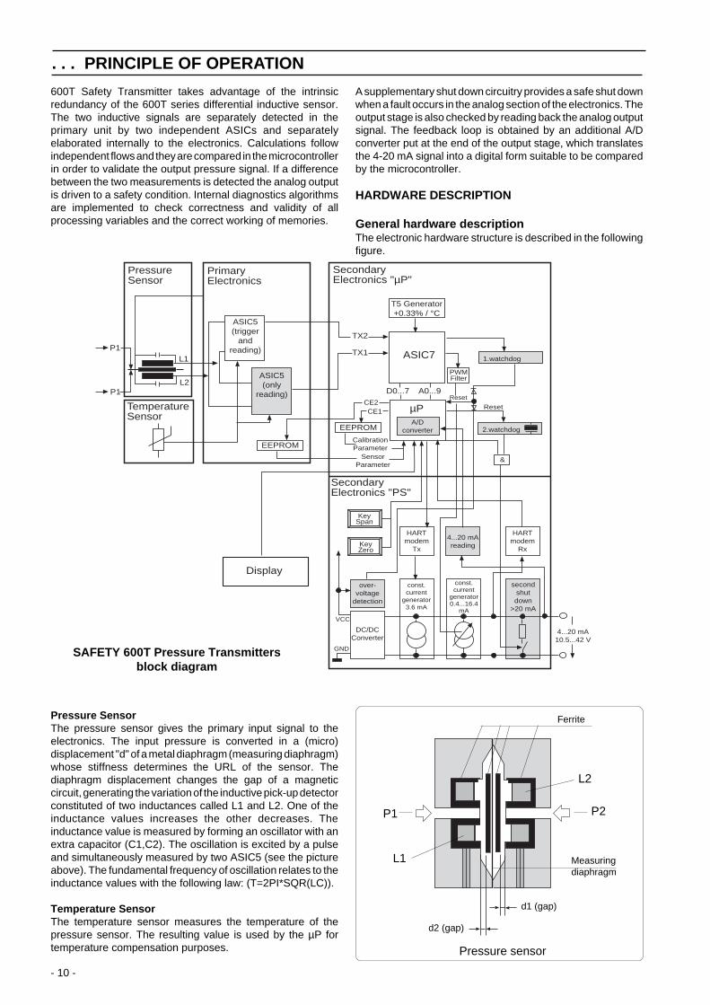
600T Safety Transmitter takes advantage of the intrinsicredundancy of the 600T series differential inductive sensor.The two inductive signals are separately detected in theprimary unit by two independent ASICs and separatelyelaborated internally to the electronics. Calculations followindependent flows and they are compared in the microcontrollerin order to validate the output pressure signal. If a differencebetween the two measurements is detected the analog outputis driven to a safety condition. Internal diagnostics algorithmsare implemented to check correctness and validity of allprocessing variables and the correct working of memories.
A supplementary shut down circuitry provides a safe shut downwhen a fault occurs in the analog section of the electronics. Theoutput stage is also checked by reading back the analog outputsignal. The feedback loop is obtained by an additional A/Dconverter put at the end of the output stage, which translatesthe 4-20 mA signal into a digital form suitable to be comparedby the microcontroller.
HARDWARE DESCRIPTION
General hardware descriptionThe electronic hardware structure is described in the followingfigure.
Pressure SensorThe pressure sensor gives the primary input signal to theelectronics. The input pressure is converted in a (micro)displacement "d" of a metal diaphragm (measuring diaphragm)whose stiffness determines the URL of the sensor. Thediaphragm displacement changes the gap of a magneticcircuit, generating the variation of the inductive pick-up detectorconstituted of two inductances called L1 and L2. One of theinductance values increases the other decreases. Theinductance value is measured by forming an oscillator with anextra capacitor (C1,C2). The oscillation is excited by a pulseand simultaneously measured by two ASIC5 (see the pictureabove). The fundamental frequency of oscillation relates to theinductance values with the following law: (T=2PI*SQR(LC)).
Temperature SensorThe temperature sensor measures the temperature of thepressure sensor. The resulting value is used by the µP fortemperature compensation purposes.
SAFETY 600T Pressure Transmittersblock diagram
Pressure sensor
Ferrite
L2
L1
P2P1
Measuringdiaphragm
d1 (gap)
d2 (gap)
ASIC5(trigger
andreading)
PrimaryElectronics
EEPROM
EEPROMA/D
converter
ASIC7
µP
SecondaryElectronics "µP"
ASIC5(only
reading)
T5 Generator+0.33% / °C
1.watchdog
2.watchdog
&
L1
L2
P1
P1
PressureSensor
TemperatureSensor
PWMFilter
TX2
TX1
CE2CE1
CalibrationParameter
SensorParameter
Display
ResetReset
HARTmodem
Tx
4...20 mAreading
HARTmodem
Rx
over-voltage
detection
DC/DCConverter
GND
const.current
generator3.6 mA
const.current
generator0.4...16.4
mA
secondshutdown
>20 mA
4...20 mA10.5...42 V
KeySpan
KeyZero
SecondaryElectronics "PS"
VCC
D0...7 A0...9

- 11 -
. . . PRINCIPLE OF OPERATIONPrimary ElectronicsMain purpose of this unit is to convert the pressure signal to anelectronic pulse-width signal. As help for added accuracy bothtemperatures and static pressure of the transducer aremeasured.
ASIC5The ASIC5 components contain the basic pulse width convertersthat convert the input frequency coming from the sensor in tworedundant pulse-width signals proportional to the two inductancevalues L1 and L2. The two independent output time-durationsignals from ASIC 5 are applied to the secondary unit throughindependent lines.
EEPROM1 MemoryThis EEPROM memory is used by the "µP" described later. Itcontains all the relevant information for the sensorcharacterization and for the transmitter calibration.
Secondary Electronics " µP"This unit uses a µP and an ASIC to convert the basic measureddata into correct scaled data. Compensation for temperatureand static pressure are also performed. The output data valueis converted into a pulse-width signal that is filtered and thatactivates the 4-20 mA transmitter. The bi-directional, digitalcommunication using the standard “HART” protocol isimplemented as part of this unit.
ASIC7The main input to ASIC7 are the two independent pressuresignals combined on two lines from ASIC5 called TX1 and TX2.The ASIC7 converts in two independent counter sections thepulse widths to two sets of five 24 bits numbers (A/D conversion).The pulse-width information are stored in two different RAMlocations and used by the µP to perform all the necessarycalculations and consistency checks and to calculate thecompensated output with correct scaling. Afterwards the µPwrites the calculation results into two 8 bit registers in ASIC7.
Watchdog1A watchdog function is implemented in the ASIC7. It interactswith the µP via the Reset block described later. In case of errorat first the watchdog resets the µP. After three retries it drivesthe PWM output in alarm condition (UP/DOWN scale).
HART ModemA modem circuit for demodulation is implemented in the ASICboth for receiving and transmitting.
µPThe µP performs all the calculations and the diagnostic functions.It drives also the supplementary shut down in case of errors inthe analog part.
ResetThere are four reset functions for the µP. “Power On Reset”,reset on ASIC7 request as described above and reset onpower supply too low or too high.
PWM FilterThis first order RC filter gives an average value of the pulsewidth signal from ASIC 7.
T5 Time GeneratorThe ASIC7 generates a temperature dependent current (+0.33%/ °C) applied to the T5 generation circuit that provides a timeduration signal (T5) used to measure the temperature in thesecondary electronics.
Watchdog2A secondary watchdog is used to monitor the correct working
of the main clock. In case the main clock doesn't work it givesa signal to the supplementary shutdown logic block that providesto force the output in safety condition.
4-20 mA readingThe internal microprocessor 8 bit A/D converter provides toconvert to a digital value the analog feedback signal from the4÷20 mA output current loop. The obtained value is internallycompared with the digital value of the actual output current fordiagnostic purposes.
EEPROM2 MemoryThe EEPROM2 memory is used by the µP to store and readconfiguration data and data concerning calibration of the 4-20mA generator.
Secondary Electronics "PS"This unit contains the 4-20 mA transmitter, the power supplyand the basic analog part of the “HART” protocol.
Constant Current Generator 0-16 mAThis block converts the filtered DC voltage representing thepressure into a 0-16 mA current. The block is trimmed togetherwith the power supply to maintain the stable 4 mA basic currentmaking the total current 4-20 mA.
Constant Current Generator 3.6 mAThis block generates a stable current basically close to 4 mA.The current generator is also used by the HART protocol in thetransmit mode to generate a +/- 400 µA current. Externally thiswill generate a +/- 100 mV signal across a 250 ohm minimumresistor.
Local keysThe pressure transmitter has two screws hidden under thenameplate. They can be used for setting ZERO and SPANvalues in the unit. The screws turn a magnet, that closes a reedrely, that activates the µP. The ZERO gives the present sensorvalue as the reference point. The SPAN gives the presentsensor value as FULL SCALE value. The screws with themagnet can be removed to prevent unauthorized changes.
DC/DC converterThe input voltage is stabilized and regulated with a DC-DCconverter to provide the circuit power supply.
HART RxThe HART modem receiving data are pre-filtered and bufferedin this block.
Over voltage detectionThe power supply is continuously monitored. In case thevoltage exceeds a fixed dangerous value a reset command tothe microprocessor is generated.
Second shut-downAn additional current generator in parallel to the output regulatorallows having an independent shutdown of the output signal. Incase of a failure of the microprocessor due to a clock failure orof a failure in the analog output stage the second shut-down isactivated forcing in this way the output signal to the up-scalealarm value.
4÷20 mA readingA buffer amplifier connected to the microcontroller reads avoltage in the analog output stage proportional to the PWMfiltered voltage. It constitutes a feedback signal of the outputcurrent.
DisplayOptional. Not Safety relevant.

- 12 -
INSTALLATION
Fig. 6 - Mounting on 2" horizontal pipe
CAUTION - Proper location of the transmitterwith respect to the process pipe will depend upon theservice for which the instrument is used. Care should beexercised to identify correct process connections.
The secondary unit of the transmitter may be rotated through360° approx. with respect to the primary unit without degradingperformance or damaging the internal wiring. Do not force theprimary unit to rotate; use the 2 mm Allen key supplied to unlockand lock the tang grub screw (see Fig. 7). This feature, obtainedby unscrewing (one turn is sufficient) the Allen screw, isparticularly useful for reaching optimum access to the electricalconnections and visibility of the output indicator.
Fig. 4 - Process Connections(Diff. Press. Transmitter)
WARNING - In order to ensure operatorsafety and plant safety it is essential that installationis carried out by suitably trained personnel accordingto the technical data provided in the specification forthe relevant model.
The transmitter may be mounted on a vertical or horizontal 2-inch pipe (figg. 5 and 6) by means of the same mountingbracket.
Note : for other installation details see the relevant Addendum.
WARNING - For installation in Hazardous Areas,i.e. areas with dangerous concentrations of e.g. gases ordusts that may explode if ignited, the installation must becarried out in accordance with relative standards either EN60079-14 or IEC 79-14 and/or with local authorityregulations, for the relevant type of protection adopted.Together with safety information here and after enclosedsee also the Addendum for "Ex Safety" aspects which ispart of this instruction manual.
Fig. 5 - Mounting on 2" vertical pipe
Note : High side may be marked H or +Low side may be marked L or -
WARNING : The transmitter when installed inaccordance with this instruction manual will not besubjected to mechanical stresses.
WARNING: the transmitter should not be installedwhere it may be subjected to mechanical and thermalstresses or where it may be attached by existing orforeseable aggressive substances.
+

- 13 -
WARNING - For installation in Hazardous Areas, i.e.areas with danger of fire and/or explosion, prior to makingelectrical connections, ensure compliance with safetyinformation on the Safety Marking plate. Failure to complywith this warning can result in fire or explosion.
Signal terminals are located in a separate compartment of thesecondary unit housing. The housing incorporates two con-nection ports for cable glands or conduit fittings. They areprotected with a temporary plastic plug for transit purposewhich should be replaced with a suitable permanent plug in theunused port. Connections can be made by removing the cover(indicated in Fig. 7); first screw down the locking screw locatedbelow the cover, using a 3 mm Allen Key.
WARNING - For Hazardous Areas installations,theconnection of cables and conduits to the transmitter shallbe made in accordance with the requirements of therelevant type of protection. Cables and cable-glands mustbe in accordance with the type of protection.Unused openings for connection shall be closed withblanking elements suitable for the relevant type ofprotection. With the exception of intrinsically safetransmitters, the means provided for this shall be such thatthe blanking element can be removed only with the aid oftools. The blanking elements must be certified for the typeof protection. See standards either EN 60079-14 or IEC79-14. The transmitter connections must also guaranteethe degree of protection of the transmitter enclosure, e.g.IPxx according to EN 60529 standard (or IEC529). Seealso the Addendum for "IP" protection (and Ex Safety)which is part of this instruction manual.
The signal cable should be connected to the terminals markedrespectively (+) and (-). If an internal output meter - either withanalog or digital indication - is installed, it should be removedin order to make the connection, simply by pulling it out from itssocket. After the connections have been made, reinstall theoutput meter. Refer to the Meters Option addendum fordetails.
Fig. 7 - Location of the locking screwsand terminals
Grubscrew
ELECTRICAL CONNECTIONS
The power to the transmitter is supplied over the signal wiringand no additional wiring is required.The signal wiring does notneed to be shielded but the use of a twisted pair is highlyrecommended. The cable shield should be grounded in oneside only, to avoid dangerous earth paths.
WARNING - For Hazardous Areas installations,when the ambient temperature is higher than 70°C, thecable used for the connections must be suitable for 5°Cabove the ambient temperature.
Normal practice is to ground in the control room side, in whichcase the field side of the screen should be adequatelyprotected to avoid contact with metallic objects. Signal wiringmay be ungrounded (floating) or grounded at any place in thesignal loop, but for intrinsically safe installations the wiring andgrounding must follow the specific rules for this technique. Thetransmitter case may be grounded or ungrounded: a groundconnection is provided internally (in the terminal compartment)and externally.Do not run the signal wiring in close proximity to power cableor high power equipment; use dedicated conduits or trays forsignal wiring.
CAUTION - Do not connect the powered signalwiring to the mA signal testing terminals as this coulddamage the by-pass diode.
After the connections have been completed check the integrityof the cover O-ring, screw down the cover and secure it byunscrewing the safety screw.
CAUTION - Unless absolutely necessary, avoidthe removal on site of the protective cover which givesaccess to the electronic circuitry. Although the electronicsare fully tropicalized they should not be subjected tohumidity for long periods.
WARNING - For Hazardous Location installations,at least eight (8) threads on each cover must be engagedin order for the transmitter to meet (FLAME Proof -explosion-proof) requirements.
Secondary Unit
Cover locking
screws (in theposition
indicated bythe arrows)
PrimaryUnit
Removethis coverto accessterminals
Hand HeldCommunicatorTerminals Test Terminals
Output MeterSocket
Short circuit link
Ground TerminalSignal Terminals
Fig. 8a - Terminals arrangementson Safety transmitter
- 14 -
+
+
-
-
++
--
Line load
GNDPowersource
Optional
Receiver
Test points4-20 mA
250 ohm min
Internal groundtermination point
REMOTEMETER
Remoteindicator
Kent-Taylor
0
43
56 7 8
9
1020
40
0
60
100%
2 80
+-
Hand-heldcommunicator
691HT
A B C
1
D E F
2
G H I
3
J K L
4
M N O
5
P Q R
6
S T U
7
V W X
8
Y Z #
9
@ % & /
0
+-
PV
REVIEW SERIALLINK
TRIM
F1 F2 F3 F4
CONF
+
+
-
-
++
--
Line load
Internal groundtermination point
External groundtermination point
GNDPowersource
Optionalground
Receiver
Model 691HT Communicator may beconnected at any wiring terminationpoint in the loop, providing the minimumresistance is 250 ohm.If this is less than 250 ohm, additionalresistance should be added to allowcommunications.
Test points4-20 mA
250 ohm min
Hand-heldcommunicator
691HT
A B C
1
D E F
2
G H I
3
J K L
4
M N O
5
P Q R
6
S T U
7
V W X
8
Y Z #
9
@ % & /
0
+-
PV
REVIEW SERIALLINK
TRIM
F1 F2 F3 F4
CONF
. . . ELECTRICAL CONNECTIONS
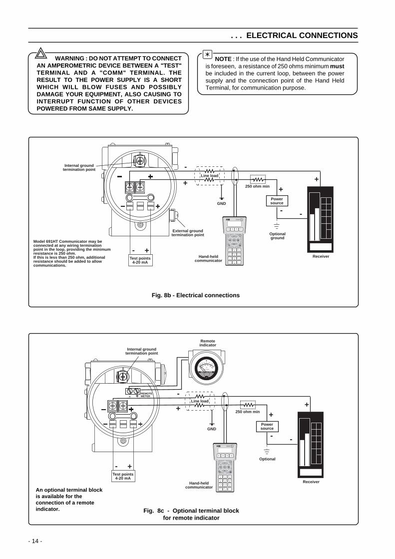
Fig. 8b - Electrical connections
Fig. 8c - Optional terminal blockfor remote indicator
An optional terminal blockis available for theconnection of a remoteindicator.
WARNING : DO NOT ATTEMPT TO CONNECTAN AMPEROMETRIC DEVICE BETWEEN A "TEST"TERMINAL AND A "COMM" TERMINAL. THERESULT TO THE POWER SUPPLY IS A SHORTWHICH WILL BLOW FUSES AND POSSIBLYDAMAGE YOUR EQUIPMENT, ALSO CAUSING TOINTERRUPT FUNCTION OF OTHER DEVICESPOWERED FROM SAME SUPPLY.
NOTE : If the use of the Hand Held Communicatoris foreseen, a resistance of 250 ohms minimum mustbe included in the current loop, between the powersupply and the connection point of the Hand HeldTerminal, for communication purpose.

- 15 -
. . . ELECTRICAL CONNECTIONS
Fig. 8d - Terminal arrangements
An enhanced version of terminal block may be present on thetransmitter.See fig. 8d. The difference in respect to the one alreadydescribed in picture 8a is that there are three terminal points,for connection to the power supply/signal and to an externalremote indicator.Refer to Electrical connections scheme in fig. 8e and fig. 8f.
M
GroundTerminal
Signal Terminals
Fig. 8e - Electrical connections
Fig. 8f - Electrical connections with remote indicator
+
+
-
-
++
--
Line load
GND
Hand-heldcommunicator
Powersource
Optional
Receiver
Test points4-20 mA
250 ohm min
Internal groundtermination point
691HT
A B C
1
D E F
2
G H I
3
J K L
4
M N O
5
P Q R
6
S T U
7
V W X
8
Y Z #
9
@ % & /
0
+-
PV
REVIEW SERIALLINK
TRIM
F1 F2 F3 F4
CONF
External groundtermination point
M
TEST COMM
+
+
-
-
++
--
Line load
GND
Hand-heldcommunicator
Powersource
Optional
Receiver
Test points4-20 mA
250 ohm min
Internal groundtermination point
Remote indicator
691HT
A B C
1
D E F
2
G H I
3
J K L
4
M N O
5
P Q R
6
S T U
7
V W X
8
Y Z #
9
@ % & /
0
+-
PV
REVIEW SERIALLINK
TRIM
F1 F2 F3 F4
CONF
External groundtermination point
M
Kent-Taylor
0
43
56 7 8
9
1020
40
0
60
100%
2 80
M+
-
TEST COMM

- 16 -
ELECTRICAL REQUIREMENTS
The transmitter operates on a minimum voltage of 10.5 Vdc toa maximum of 55 Vdc and is protected against polarityinversion.
Note - The transmitter operates from 10.5 to 42Vdc with no load (a load up to 620 Ω allows operationup to 55 Vdc). For EEx ia and intrinsically safeapproval power supply must not exceed 30 Vdc.In some countries the maximum power supply voltageis limited to a lower value.
Installing optional devices the minimum voltage increases to:- 10.5 Vdc with no option or with integral digital display- 10.7 Vdc with output analog indicator- 12.5 Vdc with output LCD indicator- 12.1 Vdc with surge protection- 14.1 Vdc with LCD indicator and surge protection- 13.1 Vdc with LCD CoMeter
The total loop resistance is indicated in the figure andexpression below.
The Smart 600T EN Transmitter Specification Sheets provideall information concerning the Range and Span limits in relationto the model and the sensor code.
The terminology currently used to define the variousparameters is as follows:
URL : Upper Range Limit of a specific sensor. The highestvalue of the measured value that the transmitter can beadjusted to measure.
LRL : Lower Range Limit of a specific sensor. The lowest valueof the measured value that the transmitter can be adjusted tomeasure.
URV : Upper Range Value. The highest value of the measuredvalue to which the transmitter is calibrated.
LRV : Lower Range Value. The lowest value of the measuredvalue to which the transmitter is calibrated.
SPAN : The algebric difference between the Upper and LowerRange Values. The minimum span is the minimum value thatcan be used without degradation of the specified performance.
TURN DOWN RATIO : is the ratio between the maximum spanand the calibrated span.
The transmitter can be calibrated with any range between theLRL and the URL with the following limitations:
LRL ≤ LRV ≤ (URL - CAL SPAN)CAL SPAN ≥ MIN SPAN
URV ≤ URL
RANGE AND SPAN CONSIDERATION
The total loop resistance is the sum of the resistance of allelements of the loop, including wiring, conditioningresistor,safety barriers and additional indicators (excluding theequivalent resistance of the transmitter).
Where a configuration device (HART), such as the Hand HeldCommunicator or a Modem is likely to be used, a resistance of250 ohm minimum should be present between the powersupply and the point of insertion of these devices, to allowcommunication.
Several types of safety barriers, either passive or active, can besatisfactorily used in conjunction with the Smart 600T ENtransmitters. Nevertheless, in case of use of active barriers,check with the supplier if the model is suitable for use withsmart transmitters allowing the connection of the configurationdevices in the "safe" or non-hazardous area.
TRANSMITTER OUTPUT SIGNALThe 600T Safety transmitter provides both the analog 4÷20 mAand the digital HART communication. HART signals do notaffect safety during trading operations. HART writings arepermitted only in maintenance (out of safety) condition.
Analog SignalTwo-wire 4 to 20 mA dc, user-selectable for linear or squareroot output; power of 3/2 or 5/2, 5th order or two 2nd orderswitching point selectable programmable polynomial outputcan be also selected for version with HART communication.
R (kΩ) =Supply voltage - min. operating voltage (Vdc)
22
HART SignalDigital process variable (%, mA or engineering units)superimposed on the 4 to 20 mA signal, with protocol based onBell 202 FSK standard.
Output current limits (compliant to NE 43 NAMURregulation)Overload condition:- Lower limit 3.8 mA dc- Upper limit : 20.5 mA dc
Transmitter failure mode (compliant to NE 43 NAMURregulation)The output signal can be user-selected to a value of 3.7 or 22mA on gross transmitter failure contition, detected by self-diagnostics.
Supply voltage
To
tal l
oo
p r
esis
tan
ce
250
(ohms)
2020
25 (ref.)10.5 55 (volts)42
4 to 20 mA andHART digital communication
620
4 to 20 mA only
600

- 17 -
The 600T Safety transmitters contain inside its non-volatilememories a number of parameters. Some of them, factorydefined, are typical of the sensor and are not user-modifiable,the other are configuration parameters and can be modified bythe user.During the normal operation status, with the transmitter insafety conditions, all remote and local configuration shall be
COMMISSIONING AND CONFIGURATION ISSUES
The transmitter is considered in safety condition (normaloperating mode) when the switch is in Write Protect (off). In thatcondition only reading commands are enabled. The specialprocedure which shall be performed to put the transmitter inoperating mode is described in the following section.
Operating mode enabling and disablingOperating mode can be enabled/disabled depending onSwitch 5 (Write) position at power on condition. The switch islocated on the secondary electronics unit under the housingcover. To ensure safety operations of the device a specificHART command shall be performed in order to enable thecondition changes.
disabled. The Safety 600T pressure transmitter is protectedagainst undesirable configuration changes by a dedicatedhardware link placed on the secondary electronics board whichis identified as Write Protect Mode Link (see fig. 9).The following figure described the maintenance-operatingphilosophy:
(Switch 5)Write Protect Modelink position at Start-up(power on)
Transmitterstatus
Operations required to pass to theopposite condition
1. Switch in OFF position2. HART Command ("Change transmitter status to operating") or Power OFF/Power ON
1. Switch in ON position2. HART Command ("Change transmitter status to maintenance") or Power OFF/Power ON
ON
OFF
Maintenance
Operating
Table 1
WARNING - After any configuration operation, the transmitter must be put in operating condition as describedin Table 1. During this change a software reset is performed and the transmitter is not working for few seconds.
COMMISSIONING/ MAINTENANCE OPERATING
HARTRead - WriteCommand
HART Read Command
Reset & Dip Switch Write Protect Mode = OFFHART command &
Dip Switch Write Protect Mode = OFF
Local KeyRead-WriteOperationand read
UP-DOWN SCALEDip Switch
HART command &Dip Switch Write Protect Mode = ON /
Reset SW andRead UP-DOWN SCALE Dip Switch
Reset & Dip Switch Write Protect Mode = ON /Read UP-DOWN SCALE Dip Switch
Configuration enable/disable switch modeled by Finite states machine
Upscale/Downscalelink
5 6
Write ProtectMode link

- 18 -
CALIBRATION
Fig. 9 Location of the links on the electronics
Unlike conventional electronic transmitters, the use of amicroprocessor and the presence of serial communicationsbetween the transmitter and the configuration device, allows theuse of several different approaches in calibration and servicing.Different methods can be used to calibrate the Safety transmitter:i) using the zero and span calibration screws in the
transmitter secondary unit.ii) using the Hand Held Communicator.iii) using the Personal Computer Configuration Software
Package.
This chapter describes the first method; the others aredescribed next or in the relevant Instruction Manuals ofconfiguration tools. If the calibration screws are not fittedcalibration must be done by method ii) or iii).In the Safety 600T EN Series it is also possible to apply ascaling to the reading of the transmitter.The operation is called PV-scaling and is used to align the"zero" of the process with the "zero" reading of the transmitter.See the description in the Addendum for PV scaling operation.
Note : Unless otherwise specified the instrument isfactory calibrated at maximum span with the LRV set to truezero. Instruments adjusted and tagged for a specific rangewill not require recalibration. Rezeroing of the transmittermay be required in order to compensate for zero shiftarising from the installation.
Preliminary operation
Before commencing calibration ensure that:i) the required span, the upper and lower range value (URV &
LRV) are within the span and range limits (URL & LRL)indicated on the nameplate (please refer to "Range andSpan" consideration on the previous page).
ii) the transmitter is properly powered and the electricalconnections correctly made.
iii) the Write Protect Mode link, located on the electronicsmodule is in position ON (write allowed). Access to the linkis gained by unscrewing the secondary unit housing coverat the opposite end to the terminal cover (See Fig. 9).
iv) the Upscale/Downscale link is positioned to the requiredfunction: ON for Downscale OFF for Upscale (see Fig. 9).
v) make the electrical connections, as indicated in Fig. 10.Connect a precision milliammeter as shown and remove theshort circuit link.
PrecisionMilliammeter
Power Supply10.5 to 42 V. d.c.55
Short circuit link
Fig. 10 - Calibration electrical connections
Set up an appropriate test rig in accordance with the requiredcalibration. Figure 11 shows a complete test rig that can beselectively used to suit the calibration.
M1
HL
A
M2
Pressure Generator orDead Weight Calibrator
M1/M2 - Pressure gauge
V.G.
V.P.
BC
V.G. - Vacuum GaugeV.P. - Vacuum Pump
Fig. 11 - Calibration pressure connections
Note that calibration accuracy is strictly related to the accuracyof the test equipment: the use of a dead weight tester is highlyrecommended.
The zero and span calibration screws are located behind theNameplate. To gain access slacken the nameplate screw androtate 90° ; proceed in the reverse mode when the calibrationprocedure has been completed. Fig. 12 shows the calibrationscrews: they provide two large plastic heads that can rotate 90°in the direction indicated by the arrows, with spring-return tonormal. The calibration screws can be removed after thecalibration, to avoid improper use by inserting a screwdriverblade below the plastic flange and pulling out.
Fig. 12 - Top view of the calibration screws
Upscale/Downscalelink
5 6
Write ProtectMode link
The calibration screws can be of type "Push buttons" withexactly the same functionality; keep it pressed for at least twoseconds.
- 19 -
. . . . CALIBRATION
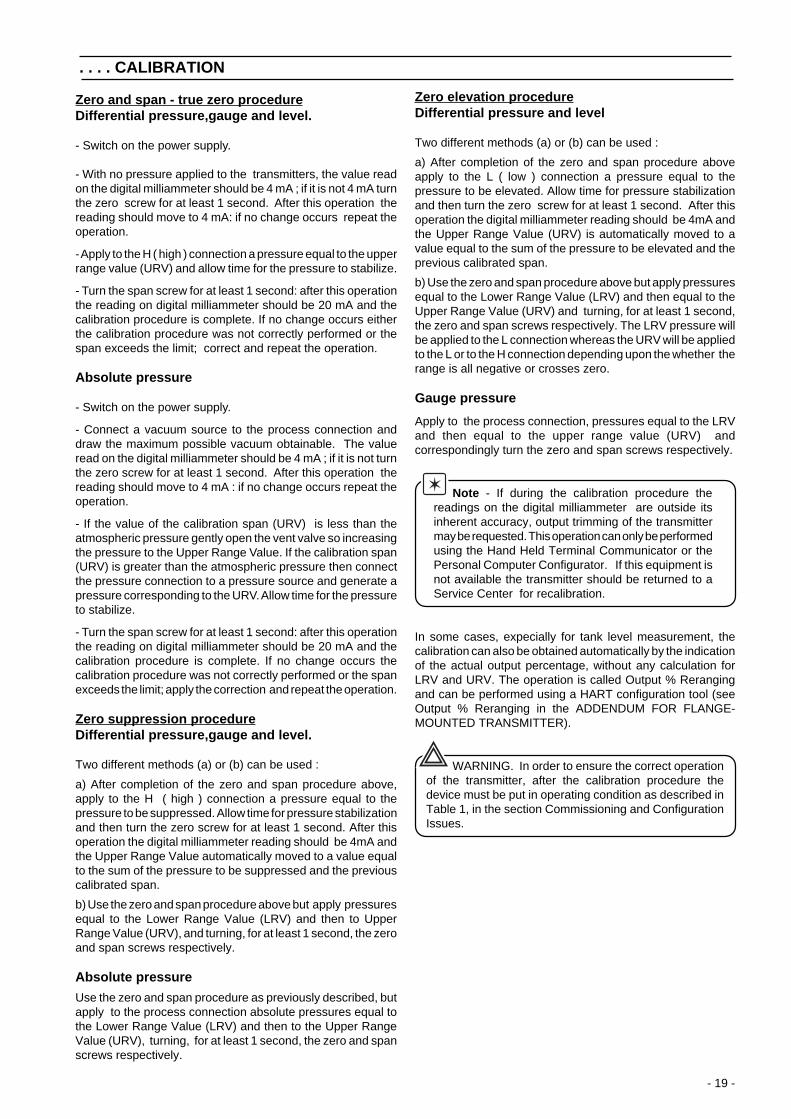
Zero and span - true zero procedureDifferential pressure,gauge and level.
- Switch on the power supply.
- With no pressure applied to the transmitters, the value readon the digital milliammeter should be 4 mA ; if it is not 4 mA turnthe zero screw for at least 1 second. After this operation thereading should move to 4 mA: if no change occurs repeat theoperation.
- Apply to the H ( high ) connection a pressure equal to the upperrange value (URV) and allow time for the pressure to stabilize.
- Turn the span screw for at least 1 second: after this operationthe reading on digital milliammeter should be 20 mA and thecalibration procedure is complete. If no change occurs eitherthe calibration procedure was not correctly performed or thespan exceeds the limit; correct and repeat the operation.
Absolute pressure
- Switch on the power supply.
- Connect a vacuum source to the process connection anddraw the maximum possible vacuum obtainable. The valueread on the digital milliammeter should be 4 mA ; if it is not turnthe zero screw for at least 1 second. After this operation thereading should move to 4 mA : if no change occurs repeat theoperation.
- If the value of the calibration span (URV) is less than theatmospheric pressure gently open the vent valve so increasingthe pressure to the Upper Range Value. If the calibration span(URV) is greater than the atmospheric pressure then connectthe pressure connection to a pressure source and generate apressure corresponding to the URV. Allow time for the pressureto stabilize.
- Turn the span screw for at least 1 second: after this operationthe reading on digital milliammeter should be 20 mA and thecalibration procedure is complete. If no change occurs thecalibration procedure was not correctly performed or the spanexceeds the limit; apply the correction and repeat the operation.
Zero suppression procedureDifferential pressure,gauge and level.
Two different methods (a) or (b) can be used :
a) After completion of the zero and span procedure above,apply to the H ( high ) connection a pressure equal to thepressure to be suppressed. Allow time for pressure stabilizationand then turn the zero screw for at least 1 second. After thisoperation the digital milliammeter reading should be 4mA andthe Upper Range Value automatically moved to a value equalto the sum of the pressure to be suppressed and the previouscalibrated span.
b) Use the zero and span procedure above but apply pressuresequal to the Lower Range Value (LRV) and then to UpperRange Value (URV), and turning, for at least 1 second, the zeroand span screws respectively.
Absolute pressure
Use the zero and span procedure as previously described, butapply to the process connection absolute pressures equal tothe Lower Range Value (LRV) and then to the Upper RangeValue (URV), turning, for at least 1 second, the zero and spanscrews respectively.
Zero elevation procedureDifferential pressure and level
Two different methods (a) or (b) can be used :
a) After completion of the zero and span procedure aboveapply to the L ( low ) connection a pressure equal to thepressure to be elevated. Allow time for pressure stabilizationand then turn the zero screw for at least 1 second. After thisoperation the digital milliammeter reading should be 4mA andthe Upper Range Value (URV) is automatically moved to avalue equal to the sum of the pressure to be elevated and theprevious calibrated span.
b) Use the zero and span procedure above but apply pressuresequal to the Lower Range Value (LRV) and then equal to theUpper Range Value (URV) and turning, for at least 1 second,the zero and span screws respectively. The LRV pressure willbe applied to the L connection whereas the URV will be appliedto the L or to the H connection depending upon the whether therange is all negative or crosses zero.
Gauge pressure
Apply to the process connection, pressures equal to the LRVand then equal to the upper range value (URV) andcorrespondingly turn the zero and span screws respectively.
Note - If during the calibration procedure thereadings on the digital milliammeter are outside itsinherent accuracy, output trimming of the transmittermay be requested. This operation can only be performedusing the Hand Held Terminal Communicator or thePersonal Computer Configurator. If this equipment isnot available the transmitter should be returned to aService Center for recalibration.
In some cases, expecially for tank level measurement, thecalibration can also be obtained automatically by the indicationof the actual output percentage, without any calculation forLRV and URV. The operation is called Output % Rerangingand can be performed using a HART configuration tool (seeOutput % Reranging in the ADDENDUM FOR FLANGE-MOUNTED TRANSMITTER).
WARNING. In order to ensure the correct operationof the transmitter, after the calibration procedure thedevice must be put in operating condition as described inTable 1, in the section Commissioning and ConfigurationIssues.

- 20 -
PRE-STARTUP ACCEPTANCE TEST
After the installation of the device in order to validate therequired safety functionality of the system together with thetarget equipment according to the Safety RequirementSpecification a Pre-Startup Acceptance test shall be performedas following:
1. Put the Write Protect Mode switch in operating position2. Power-on the transmitter: the transmitter performs
automatically a self-test that consists in the operationsbelow:- Switch-on of the Secondary output- Test of the analog output stage and of the feedback A/D converter
In case the first condition wouldn't happen, the transmitter shallbe considered failed and not possible to use. In case thesecond test would fail the transmitter will drive the output to theselected alarm status. In this case a correction action consistsin the re-calibration of the A/D converter. After the correctionaction the pre-startup test shall be repeated.3. Put the Write Protect Mode switch in Write Enable condition.4. Perform the Hart Command "Change Transmitter status to
Maintenance"5. Perform the Hart Command "Clock monitor test". The
transmitter simulates a clock failure and put the output toUp-scale by the supplementary output stage. In case thiscondition wouldn't happen, the transmitter shall beconsidered failed and not possible to use.
6. Power-off the transmitter7. Put the Operating/maintenance switch in operating condition8. Power-on the transmitter.
A pre-startup acceptance test report shall be produced torecord the test results.
PROOF TESTS
Safe undetected faults could occur during the operation of thetransmitters. These failures do not affect the transmitteroperations. To maintain the claimed Safety Integrity Level(SIL 2) a proof test procedure is requested every 1 year .The proof tests consists in the following operations:
1. Put the Write Protect Mode switch in Write Enable condition.2. Perform the Hart Command "Change Transmitter status to
Maintenance"3. Perform the Hart Command "Clock monitor test". The
transmitter must go to up-scale setting the secondaryoutput stage. To recover from the alarm status a power-off,power-on operation is required.
4. Power-off the transmitter5. Put the Write Protect Mode switch in Write Disable condition.6. Power-on the transmitter. The transmitter must go first to
up-scale setting the secondary output stage, then finally theoutput must provide the actual pressure value.
Location of the links on the electronics
Upscale/Downscalelink
5 6
Write ProtectMode link

- 21 -
DISMANTLING AND REASSEMBLY
WARNING - Process fluids and/or pressureretained in the transmitter primary unit can causesevere injury and death or damage to theequipment. Plant Safety Procedures must befollowed when removing the instrument fromservice or when draining or venting.
CAUTION - Dismantling and reassembly shouldnot be carried out on site because of the risk ofdamage to components and printed circuits as a resultof adverse environmental conditions such ashumidity,dust,etc. The dismantling and reassemblyprocedures given below should be carried out in thelisted order to avoid instrument damage.
Required tools2 mm Allen key3 mm Allen keySmall Phillips screwdriverSmall flat-bladed screwdriver17 mm spanner17 mm torque wrench - (Range > 52 Nm - 39 foot lbs)
Dismantlinga) Screw down completely the cover locking screw, electronics
side, using the 3 mm Allen keyb) Unscrew and remove the coversc) Unscrew the two fixing screws and remove the
secondary electronic assemblyd) Unplug the sensor cablee) Remove the tang grub screw using the 2 mm Allen keyf) Unscrew the housing taking care not to damage the
sensor cable or the connectorg) Loosen and remove the four flange fixing bolts using a
17 mm. spanner.
Reassembly
Check that the "O" rings are not damaged : if in replace.
WARNING - Assembling flanges with incorrectfixing bolts and nuts and improper "O rings" cancause fracture or overstressing of bolts and releaseof pressurized process material. Use only officialspare parts and do not exceed the specified torquelimits. DO NOT REMOVE the "O ring" fitted in thesensor neck: it provides the housing a degree ofprotection.
a) Refit the flange fixing bolts with a torque of 20 Nm (15 ft lbs)using a 17 mm. torque wrench.
1 Nm is equivalent to 0.738 ft lbs (8.85 in lbs)
b) Insert the sensor cable in its recess at the bottom of thehousing.
c) Screw the housing down completely until the nesting ofhousing/sensor assy is reached, then unscrew by onecomplete turn maximum. Rotate the topwork in thedesired position and lock it with the tang grub screwpreviously removed.
d) Plug the sensor cable to the secondary electronics. Fixthe electronic circuit by its screws.
e) Refit the covers and tighten securely.
WARNING - For Hazardous Locationinstallations, at least eight (8) threads on thecover must be engaged in order to meet theflameproof (explosion-proof) requirements.
f) Unscrew the cover locking screw to secure the covers.This is mandatory to meet "Flameproof requirements"for Hazardous Areas installation.
Fig. 13 - Transmitter Sectional View
Secondaryelectronics
Electronics screw
Blind cover
Flange bolts
Analog, digitaloutput indicator
or CoMeter
Extendedwindowed cover
Blind cover
Tangscrew
Terminal blocksassembly
Sensor assembly
Calibration screws
Nameplate
WARNING - L'elettronics unit andtransducer are inseparable parts of the600T Safety transmitters. Any replace ofthese two parts outside the factory willresult of a less of the claimed SIL.

- 22 -
Start (power off)
OK
No output
OK
Repair or replacepower supply
Check the transmitterpower supply (*)
Check the transmitterpower supply (*)
Stop
Repair or replacepower supply
High, Low or Irregular Output
Start (power off)
OK
OK
OK
Clean out
Remedy
Faulty
Still faulty
OK
OK
Fit replacementelectronic circuit
Faulty
StopOK
Fit replacementtransducer assembly
Still faulty
Stop
Stop
Stop
StopOK
Clean connectors.Reassemble, switch on andcheck instrument operation
Faulty
Check for trapped gasin liquid lines and liquidin dry lines
Check for sedimentin process flange (**)
Disconnect sensorconnector from theelectronic circuit.Clean connector,Reassemble, switch onand check instrumentoperation
Fit replacementelectronic circuit
Fit replacementtransducer assembly
Stop
Present
Present
Faulty
SIMPLE FAULT FINDING (HART)
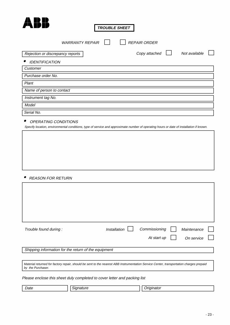
This part is applicable only for a quick fault finding in the case that the Hand Held Terminal or the P.C. Configurator Packageare not available.If the transmitter does not appear to be working satisfactory, carry out the following fault finding checks before contacting yournearest Service Centre.If the instrument is to be returned for repair, ensure that it is adequately packed using the original polystyrene box or high densitychip foam: the trouble sheet/returning form should be sent with the instrument, filled in all its parts. If the transmitter needsto be dismantled follow the procedures as described in the previous section.
WARNING : If the transmitter forms part of a control loop, the plant must be placed under local manualcontrol while the instrument is examined or taken out of service. Take all precautions to avoid damages causedby pressure or dangerous fluids release.
Equipment neededVoltmeter , milliammeter (0 to 100 mA d.c.), solvent contact cleaner.
(*) If the source of the problem is suspected to be the power supply, check it by disconnecting the wires from the transmitterand testing the volts available at the wires.
(**) If there are sediments in process flanges they must be cleaned, if inevitable flanges have to be removed. Before reassemblypay attention to the O-ring: Teflon O-ring probably requires to be substituted. Refer to dismantling and reassembly sectionfor these operations.
WARNING - If the transmitter needs to berepaired, the faulty unit/assembly must be replaced by anequivalent unit/assembly.
- 23 -
Specify location, environmental conditions, type of service and approximate number of operating hours or date of installation if known.
• OPERATING CONDITIONS
• REASON FOR RETURN
Trouble found during :
Customer
Purchase order No.
Plant
Name of person to contact
Instrument tag No.
Model
Serial No.
WARRANTY REPAIR REPAIR ORDER
• IDENTIFICATION
Rejection or discrepancy reports Not availableCopy attached
Shipping information for the return of the equipment
MaintenanceCommissioningInstallation
On serviceAt start up
Please enclose this sheet duly completed to cover letter and packing list
Date Signature Originator
Material returned for factory repair, should be sent to the nearest ABB Instrumentation Service Center, transportation charges prepaidby the Purchaser.
TROUBLE SHEET

- 24 -
ADDENDUM FOR "METERS" OPTION OF THE TRANSMITTERS
GENERAL DESCRIPTION
This option provides three different indications (meters) inside the transmitter housing. The "output meters" can be mounted onthe terminal block (field terminals) side; one is of "analog" type, the second is of "digital" type (LCD, 3 1/2 -digit) and the thirdis the CoMeter. They are operated by the output signal of the transmitter. The meters can be rotated to exactly match the mountingposition of the transmitter (see Figs. 1, 2 and 5). The above mentioned CoMeter (abbreviation of Communication Meter) can beused both as a display and as a configuration tool for the Safety 600T.
Fig. 1 - Analog meter adj.
0 100
4
%
806040
20
20
128 16mA
Zero adj.
ANALOG OUTPUT METER
The analog output meter provides a 90° scale indication. It haseither a 0 to 100 linear scale or a 0 to 10 square root scale.
ANALOG OUTPUT METER CALIBRATION
The calibration of the analog type meter only involves zeroing.Fig. 1 shows the analog output meter and the location of thezero adjustment.The calibration is quite simple using one of the followingmethods:- with the loop unpowered adjust the zero screw to read exactly
the true zero mark on the scale (Fig. 1).- with the transmitter transmitting 4 mA adjust the zero screw
to read exactly the live zero of the scale.
Zero/spanadjustments
Standard position
Multiplicationfactor label
Units label
SwitchesSW1, SW2 : zero, elev./supp.SW3, SW4 : span adj.SW5, SW6 : decimal point posit.
kPax 10
Z S
ON
1 2 3 4 5 6
Fig. 2 - LCD output meter front view
90° max.clockwise from standard
position
255° max.counter-clockwise
from standard position
DIGITAL OUTPUT METER
The digital output meter has a 3 1/2-digit, 10 mm (3/8 in) highliquid crystal display (LCD). The maximum count is 1999.
DIGITAL OUTPUT METER CALIBRATION
The LCD digital type output meter can be calibrated, to indicatethe output current, output as a percentage or the processvalue. Meter calibration may be accomplished during calibrationof the transmitter or utilizing the capability of the 600T Safetytransmitter as a current generator. However the latter can beused only in conjunction with the Hand Held Communicator ora suitable P.C. based program.

- 25 -
. . . ADDENDUM FOR "METERS" OPTION OF THE TRANSMITTERS
The calibration can be performed in output current or percentage,or in process engineering units (see fig. 2).Proceed as follows:
A) OUTPUT CURRENT (4÷20 mA)1) The switches from SW1 to SW6 must be positioned as
follows : ON - OFF - ON - OFF - ON - OFF
2) Set the output current of the current generator to 4 mA,reading it on the milliammeter or 1 V. on the DVM.Alternatively force, using the "Loop Test" procedure onthe Hand Held Communicator, the output of your Safetytransmitter to 4 mA.
3) Adjust the zero trimmer (Z) to read approximately 4.004) Set the output current to 19.9 mA, reading it on the
milliammeter, or 4.975 V. on the DVM. Alternativelyforce the output of your Safety transmitter to 19.9 mAchecking for this value in the Hand Held Communicator.
5) Adjust the span trimmer (S) to read approximately 19.90.6) Repeat the points 2) 3) to read exactly 4.00 (± 0.1)7) Repeat the points 4) 5) to read exactly 19.90 (± 0.1).8) Fit the "mA" unit label in the right recess below the
indication.B) OUTPUT PERCENTAGE (0÷100%)
1) The switches from SW1 to SW6 must be positioned asfollows : ON - OFF - ON - ON - OFF - ON
2) Set the output current of the current generator to 4 mA,reading it on the milliammeter or 1 V. on the DVM.Alternatively force, using the "Loop Test" procedure onthe Hand Held Communicator, the output of your Safetytransmitter to 4 mA.
3) Adjust the zero trimmer (Z) to read approximately 00.04) Set the output current to 20 mA, reading it on the
milliammeter, or 5 V. on the DVM. Alternatively force theoutput of your Safety ransmitter to 20 mA checking forthis value in the Hand Held Communicator.
5) Adjust the span trimmer (S) to read approximately 100.0.6) Repeat the points 2) 3) to read exactly 00.0 (± 0.1)7) Repeat the points 4) 5) to read exactly 100.0 (± 0.1)8) Fit the "%" unit label in the right recess below the
indication.C) ENGINEERING UNITS
The switches must be positioned as follows:
-1999 ÷ -1000
-1000 ÷ 0
0 ÷ 1000
1000 ÷ 1999
OFF
ON
OFF
ON
OFF
OFF
ON
ON
SW1 SW2 For ZERO adjustment, between
100 ÷ 1000
1000 ÷ 2000
2000 ÷ 3000
3000 ÷ 3998
ON
OFF
ON
OFF
ON
ON
OFF
OFF
SW3 SW4
4.00 ÷ 19.99
40.0 ÷ 199.9
400 ÷ 1999
OFF
ON
OFF
ON
OFF
OFF
SW5 SW6
For SPAN adjustment, between
For DECIMAL POINT position, like
Then proceed as follows:1) Set the output current of the current generator to 4 mA on
the milliammeter or 1 V. on the DVM. Alternatively, usingthe "Loop Test" procedure on the Hand HeldCommunicator, force the output of your Safety ransmitterto 4 mA.
2) Adjust the zero trimmer (Z) to read approximately thelower range value (LRV) on the digital meter.
3) Set the output current to 20 mA, on the milliammeter or5 V. on the DVM. Alternatively force the output of theSafety transmitter to 20 mA using the Hand HeldCommunicator.
4) Adjust the span trimmer (S) to read approximately theupper range value (URV) on the digital meter.
5) Repeat the points 1) 2) to read exactly the LRV (± 0.1).6) Repeat the points 3) 4) to read exactly the URV (± 0.1).7) Complete the calibration procedure by fitting the
multiplication factor label (if any) in the left recess belowthe display and the engineering unit label in the rightrecess (see fig. 2).

- 26 -
. . . ADDENDUM FOR "METERS" OPTION OF THE TRANSMITTERS
Fig. 3 - Cover Internal label
3) Remove the link shown on the label by pushing down at itsleft extremity and then its right . Alternatively it can beremoved on the left side only in preparation for a furtherrefit.
4) Plug the meter into the socket. The digital indication metercan rotate, for easy viewing, in 15° steps, 90° degreeclockwise and 255° counterclockwise, as shown in figure 2.Further rotation causes damage to the meter stops or to the"banana" connections and should be avoided. Note thatconsiderable effort must be applied for 15° rotation. Theanalog output meter can also rotate for easy viewing.
5) Check that the cover O-ring gasket is properly in place,screw on the extended windowed cover and tighten properly.
To remove the meter simply pull it out from the socket and fita replacement following the above procedure.
CAUTION - If the meter is removed, ensure that it isreplaced immediately by another one or with the properlink provided. This operation is important for I.S.loop operation.
METER INSTALLATION OR REPLACEMENT
WARNING - If the transmitter is not certified asIntrinsic Safety type, DO NOT REMOVE ANY COVERin areas classified as "HAZARDOUS LOCATIONS:CAN RESULTS IN HAZARD OF FIRE ANDEXPLOSION". Contact your Safety Dpt. in order toestablish correct installation procedure.
To install (or to replace) the meter, use the following procedure:1) If the transmitter is part of a control loop, put the loop in
manual.2) Remove the cover on the terminal block side; inside of
which is affixed the label shown in Fig. 3.
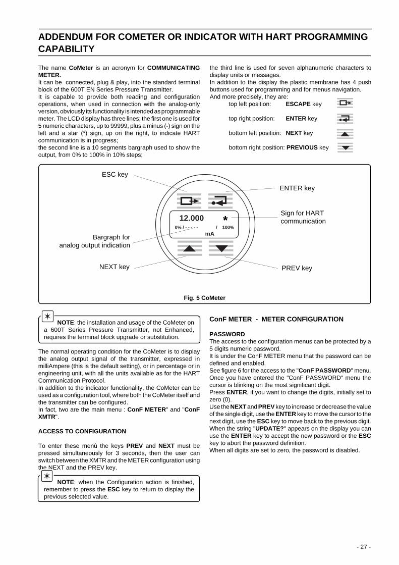
- 27 -
The name CoMeter is an acronym for COMMUNICATINGMETER.It can be connected, plug & play, into the standard terminalblock of the 600T EN Series Pressure Transmitter.It is capable to provide both reading and configurationoperations, when used in connection with the analog-onlyversion, obviously its functionality is intended as programmablemeter. The LCD display has three lines; the first one is used for5 numeric characters, up to 99999, plus a minus (-) sign on theleft and a star (*) sign, up on the right, to indicate HARTcommunication is in progress;the second line is a 10 segments bargraph used to show theoutput, from 0% to 100% in 10% steps;
ADDENDUM FOR COMETER OR INDICATOR WITH HART PROGRAMMINGCAPABILITY
the third line is used for seven alphanumeric characters todisplay units or messages.In addition to the display the plastic membrane has 4 pushbuttons used for programming and for menus navigation.And more precisely, they are:
top left position: ESCAPE key
top right position: ENTER key
bottom left position: NEXT key
bottom right position: PREVIOUS key
Fig. 5 CoMeter
NOTE: the installation and usage of the CoMeter ona 600T Series Pressure Transmitter, not Enhanced,requires the terminal block upgrade or substitution.
The normal operating condition for the CoMeter is to displaythe analog output signal of the transmitter, expressed inmilliAmpere (this is the default setting), or in percentage or inengineering unit, with all the units available as for the HARTCommunication Protocol.In addition to the indicator functionality, the CoMeter can beused as a configuration tool, where both the CoMeter itself andthe transmitter can be configured.In fact, two are the main menu : ConF METER " and "ConFXMTR".
ACCESS TO CONFIGURATION
To enter these menù the keys PREV and NEXT must bepressed simultaneously for 3 seconds, then the user canswitch between the XMTR and the METER configuration usingthe NEXT and the PREV key.
NOTE: when the Configuration action is finished,remember to press the ESC key to return to display theprevious selected value.
ConF METER - METER CONFIGURATION
PASSWORDThe access to the configuration menus can be protected by a5 digits numeric password.It is under the ConF METER menu that the password can bedefined and enabled.See figure 6 for the access to the "ConF PASSWORD " menu.Once you have entered the "ConF PASSWORD" menu thecursor is blinking on the most significant digit.Press ENTER, if you want to change the digits, initially set tozero (0).Use the NEXT and PREV key to increase or decrease the valueof the single digit, use the ENTER key to move the cursor to thenext digit, use the ESC key to move back to the previous digit.When the string "UPDATE? " appears on the display you canuse the ENTER key to accept the new password or the ESCkey to abort the password definition.When all digits are set to zero, the password is disabled.
ESC key
Bargraph foranalog output indication
NEXT key
ENTER key
Sign for HARTcommunication
PREV key
12.000 *0% / - - - - - / 100%
mA
*
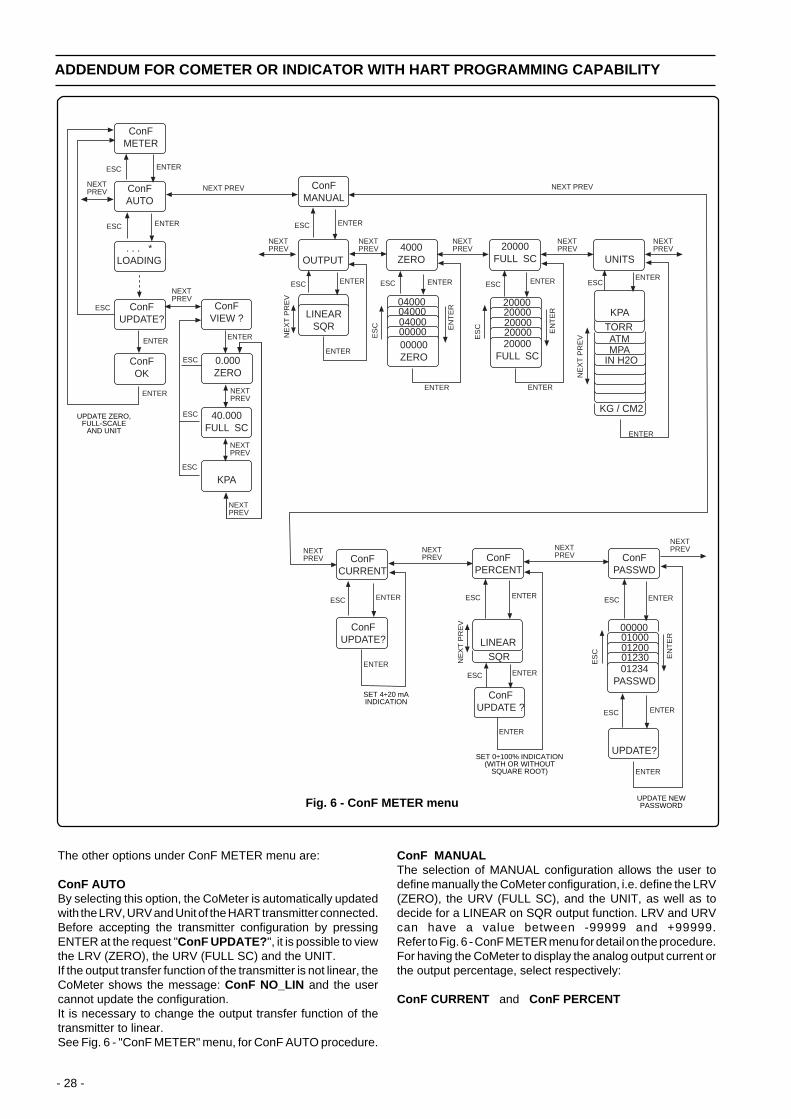
- 28 -
Fig. 6 - ConF METER menu
ConFMETER
ENTER
ConFAUTO
ESC
ENTER
ESC
. . . *LOADING
NEXTPREV
ENTER
NEXTPREV
ConFUPDATE?
ConFVIEW ?
ESC
ESC
ESC
0.000ZERO
40.000FULL SC
KPA
ConFMANUAL
OUTPUT
LINEARSQR
ESC ENTER
NEXTPREV
NE
XT
PR
EV
4000ZERO
0400004000040000000000000ZERO
20000FULL SC
20000FULL SC
20000200002000020000
NEXTPREV
NEXTPREV
ENTER
ES
C EN
TE
R
ESC ENTER ESC ENTER
EN
TE
R
ES
C
ENTER
ESCENTER
UNITS
NE
XT
PR
EV
KPATORRATMMPA
IN H2O
KG / CM2
ENTER
NEXT PREVNEXT PREV
ENTER
ENTER
NEXTPREV
NEXTPREV
NEXTPREV
ENTER
ConFCURRENT
ConFUPDATE?
ConFPERCENT
ESC ENTER
ENTER
ConFPASSWD
NEXTPREV
NEXTPREV
ESC ENTER
LINEAR
ConFUPDATE ?
SQR
ESC ENTER
NE
XT
PR
EV
01234PASSWD
00000010000120001230 E
NT
ER
ES
C
UPDATE?
ESC ENTER
ESC ENTER
ENTER
ENTER
NEXTPREVNEXT
PREV
ESC
ConFOK
ENTER
ESC
NEXTPREV
NEXTPREV
The other options under ConF METER menu are:
ConF AUTOBy selecting this option, the CoMeter is automatically updatedwith the LRV, URV and Unit of the HART transmitter connected.Before accepting the transmitter configuration by pressingENTER at the request "ConF UPDATE? ", it is possible to viewthe LRV (ZERO), the URV (FULL SC) and the UNIT.If the output transfer function of the transmitter is not linear, theCoMeter shows the message: ConF NO_LIN and the usercannot update the configuration.It is necessary to change the output transfer function of thetransmitter to linear.See Fig. 6 - "ConF METER" menu, for ConF AUTO procedure.
ConF MANUALThe selection of MANUAL configuration allows the user todefine manually the CoMeter configuration, i.e. define the LRV(ZERO), the URV (FULL SC), and the UNIT, as well as todecide for a LINEAR on SQR output function. LRV and URVcan have a value between -99999 and +99999.Refer to Fig. 6 - ConF METER menu for detail on the procedure.For having the CoMeter to display the analog output current orthe output percentage, select respectively:
ConF CURRENT and ConF PERCENT
ADDENDUM FOR COMETER OR INDICATOR WITH HART PROGRAMMING CAPABILITY
UPDATE ZERO,FULL-SCALE
AND UNIT
SET 4÷20 mAINDICATION
SET 0÷100% INDICATION(WITH OR WITHOUT
SQUARE ROOT)
UPDATE NEWPASSWORD

- 29 -
Under ConF PERCENT option, the user can decide for linearor SQR output. When SQR output is selected, the output islinear from 0 to 20% (to 4% of input).Refer to Fig. 6 - ConF METER for details on the procedures.
ConF XMTR - TRANSMITTER CONFIGURATION
Four are the operations under the ConF XMTR menu:CONF, TRIM, REVIEW and PV.By pressing ENTER on the ConF XMTR menu, the stringLOADING appears on the display, with the blinking star (*)indicating communication activity, i.e. the CoMeter is readingthe transmitter information.
See below a list of the available operation under the selected option:
CONF menu TRIM menu REVIEW menu PV menu
Change LRV Reranging (RERANG.) TAG 8 Primary variable (PRIMARY)Change URV Loop test (LOOPTST) Final Assembly Nr. (XMTR N.) Secondary variable (2ND)Change DAMPING Output trim (OUTTRIM) Sensor Serial Nr. (SENS N.) Tertiary variable (3RD)Change UNITS Zero adjustment (SNSZERO) Up/Down scale (UP/DOWN) Fourth variable (4TH)Change OUTPUT UNITS
LRVURVLRL (See Sensor Units)URL (See Sensor Units)DAMPINGOUTPUT
Then the CONF option appears.Using PREV or NEXT key, the user can select CONF, TRIM,REVIEW or PV option, and with the ENTER key he moves intothe menu.When entering CONF and TRIM menu a message "LOOPIN_MAN" appears to remind that a modification can changethe transmitter output, so for security the loop should be put inManual.
Use PREV or NEXT key to scroll through the options and ENTER key to change or view the values.The procedure to change the numeric value remains the one already explained for PASSWORD operation, i.e., the cursor startsblinking on the most significant digit, then use the NEXT and PREV key to increase or decrease the value of the single digit (theminus sign(-)automatically appears or disappears when the value increases above 9 or decreases below 0, as well as for thedecimal point(.). Use the ENTER key to move the cursor to the next digit, use the ESC key to move back to the previous digit.
An ENTER on the last digit will cause the value to be sent to the transmitter.Refer to figures 7, 8, 9 and 10 for details.
Fig. 7 - CONF menu
CONF
LOOPIN_MAN.
ESC ENTER
NEXTPREV
ESC ENTER
0.000LRV
ESC ENTER
00.00001.00001.00001.000
01.000LRV
ES
C EN
TE
R
NEXT PREV 20.000URV
ESC ENTER
20.00025.00025.00025.000
25.000URV
ES
C EN
TE
R
NEXT PREV 0.0000DAMPING
ESC ENTER
0.00000.20000.20000.2000
0.2000DMP SEC
ES
C EN
TE
R
NEXT PREV
ENTER
UNITS
ENTER
KPA
NE
XT
PR
EV
ENTER
ESC
TORRATMMPA
IN H2O
KG/CM2
OUTPUT
ENTER
LINEAR
ESC
SQR
NEXT PREV
NE
XT
PR
EV
ES
C
ES
C
ES
C
ES
C
ENTER ENTER
NEXTPREV
NEXT PREVTO MODIFY DIGIT,DECIMAL POINT,
MINUS SIGN
NEXT PREVTO MODIFY DIGIT,DECIMAL POINT,
MINUS SIGN
NEXT PREVTO MODIFY DIGIT,DECIMAL POINT,
MINUS SIGN
ADDENDUM FOR COMETER OR INDICATOR WITH HART PROGRAMMING CAPABILITY

- 30 -
Fig. 8 - TRIM menu
TRIM
LOOPIN_MAN.
ESC ENTER
NEXTPREV
ESC ENTER
RERANG.
ESC ENTER
0.000SET 4 mA
NEXT PREV
LOOPTST
ESC ENTER
4 mA
ES
C
NEXT PREV
20 mA
ESC ENTER
20.000OUT mA
NEXTPREV
OUTTRIM
ENTER
SNSZERO
ENTER
APPLY PV
ESC
NEXT PREV
ES
C
ENTER
40.000SET 20 mA
ENTERESC ENTER
4.000OUT mA
NEXTPREV OTHER
ESC
10.000
ENTER
12.00012.00012.00012.000
SEL OUT
ES
C
EN
TE
R
12000OUT mA
ENTER
MANUAL
ENTER
SET 4mA
ENTER
04.00004.00004.000
ES
C
EN
TE
R
04.000
04.000REF VAL
4.000REF - TX?
ENTER
SET20 mA
ENTER
ENTER
20.00020.00020.000
ES
C
EN
TE
R
20.000
20.000REF VAL
20.000REF = TX?
ENTER
ENTER
AUTO
SET 4mA
4.001TRIM ?
ENTER
ENTER
NEXT PREV
ENTER
ENTER
ENTER
0.050 KPA
ESC
ENTER
ESC
NEXTPREV
ESC
ESC
ESC
ESC
ESC
ESC
NEXT PREV
SET 20mA
20.000TRIM ?
ENTER
ENTER
ESC
ESC
ADDENDUM FOR COMETER OR INDICATOR WITH HART PROGRAMMING CAPABILITY
NEXT PREVTO MODIFY DIGIT,DECIMAL POINT,
MINUS SIGN
NEXT PREV TO MODIFY DIGIT,DECIMAL POINT, MINUS SIGN
NEXT PREV TO MODIFY DIGIT,DECIMAL POINT, MINUS SIGN

- 31 -
Fig. 9 - REVIEW menu
REVIEW
ENTER
TAG 8
ESC
ENTER
ABCDEFG
NEXTPREV
NEXT PREV
(SCROLL)
ESC
XMTR N'
1234567
ESC ENTER
NEXT PREV
(SCROLL)
ESC
SENS N'
1234567
ESC ENTER
NEXT PREV
(SCROLL)
ESC
UP/DOWN
UP
ESC ENTER
ESC
UNITS
KPA
ESC ENTER
ESC
0.000LRV
ESC
40.000URV
ESC
-40.000LRL
ESC
40.000URL
ESC
1.0000DAMPING
ESC
OUTPUT
LIN
ESC ENTER
ESC
NEXTPREV
NEXT PREV
Fig. 10 - PV menu
ENG.UNITS
PV
ENTER
PRIMARY
ESC
ENTER
10 sec. 10.690KPA
NEXTPREV
or
8.280mA
2ND
27.000DEG.C
NEXT PREV
ENTER
or
26.750%
3RD
10.000MPA
NEXT PREV
ENTER
4TH
200Lt/min
NEXT PREV
ENTER
NEXT PREV
ESCESCESC
10 sec.
10 sec.
ANALOGOUTPUT
OUTPUT%
10 sec. 10 sec.10 sec.
ADDENDUM FOR COMETER OR INDICATOR WITH HART PROGRAMMING CAPABILITY

- 32 -
PV-scaling operation can be used to align the "zero" of theprocess with the "zero" reading of the transmitter. A configurationtool must be use to perform this operation through digitalcommunication.
1) PV scaling for analog + HART Safety version
There are two different ways to perform a PV-scaling.Method 1: apply to the transmitter a pressure that corresponds
to the scaling value (offset) you have to apply to thereading and perform the operation using theconfiguration tools. The operation is called SET PVZERO (see example 1).
Method 2: calculate the scaling value (offset) and apply it to thetransmitter following the operation available on theconfiguration tool. With this method it is possible toperform a scaling operation even for a value differentthen zero. The operation is called SET PV VALUE(see example 2).
Effect of the PV-scaling operation:An example can better explain the effect of the scaling action.
Example n ° 1the transmitter is calibrated at:
LRV = 0 mbarURV = 200 mbar
the transmitter model has the following limits of operation:LRL = -400 mbarURL = +400 mbar
For the effect of a transmitter's capillary, connected to a tank,there is a pressure of 80 mbar when the tank is empty, i.e. thetransmitter's reading is 80 mbar.In order to eliminate the pressure caused by the fluid inside thecapillary, you can perform a PV scaling for compensating/scaling the reading for these 80 mbar. The result of thisoperation is:
the transmitter's reading is now 0 mbar.offset is -80 mbar and must be considered that while thelimits of the transmitter remains:
LRL = -400 mbarURL = +400 mbar
and the calibration does not changeLRV = 0 mbarURV = 200 mbar
The configuration tools allows you to evaluate the newoperative limits:
operative LRL = -480 mbaroperative URL = +320 mbar
Example n ° 2the transmitter is calibrated at:
LRV = 0 mbarURV = 200 mbar
the transmitter model has the following limits of operation:LRL = -400 mbarURL = +400 mbar
the transmitter is reading:PV = 100 mbar
and you know the process value is 50 mbar.
ADDENDUM FOR PV-SCALING OPERATION
You can apply this 50 mbar for your PV scaling operation, withsimilar effect as per the previous example:
PV reading = 50 mbaroffset = 50 mbar so that while the limits of thetransmitter remains:
LRL = -400 mbarURL = +400 mbar
with no change for the calibration, the configurationtools allows you to display the new operative limits:
operative LRL = -450 mbaroperative URL = +350 mbar
When requested it is possible to reset the value actuallyapplied as offset.When an offset is defined, the trimming operations aredisabled and can be rehabilitated only by eliminating thescaling, i.e. setting the offset to 0.
WARNING. In order to ensure the correct operationof the transmitter, after the calibration procedure thedevice must be put in operating condition as described inSection 7.1

- 33 -
ADDENDUM FOR "SURGE PROTECTION" OPTION OF THE TRANSMITTERS
GENERAL DESCRIPTION
This option provides a built-in surge protection circuit.The surge protector is designed to dissipate large quantities of electrical energy which have been induced in a transmission line.The option is suitable to protect up to 2500 V (5 kA discharge current) of 8µs rise time/20µs decay to half value.These large quantities of energy can be induced in the signal transmission line by lightning discharge in the area or by nearbyelectrical equipment.The dissipation of this energy prevents damage to transmitter circuitry connected to the transmission line.
The surge protector will not protect the instrument in case of a direct lightning strike.
The surge protector board is located inside the terminal block of the transmitter (see drawing).The circuit is designed to operate and recover automatically. It does not require periodic testing or adjustment.
FITTING PROCEDURE (refer to figures)
CAUTION : This procedure should not be carried out on the field site.
a) Remove the transmitter cover of the field connections side.b) Unplug the built-in indicator, if present.c) Unscrew the two Phillips screws (M 4 x 18 mm) which secure the terminal block and pull it off the housing.d) Unscrew the two Phillips screws (M 3 x 6 mm) which fix the wire eyelet terminals of the two RF (radio frequency) filters, on
the back of the terminal block. Retain the screws.e) Fit properly the surge protector p.c. board and secure it by a self-tapping screw (M 2.9 x 6mm)f) Secure the two +/- eyelet terminals to +/- threaded holes on the back of the terminal block, by the two Phillips screws (M
3 x 6 mm) previously removed.g) Secure the two +/- wire eyelet terminals of the RF filters to the +/- threaded bushes of the p.c. board by two Phillips screws
(M 3 x 6 mm).h) Connect the wire eyelet terminal of the Surge Protector to the dedicated ground connection below terminal block, using a
provided self tapping screw M4x8 mm and relevant washers.i) Reinstall the terminal block and stick on the notice label in the proper position.l) Plug the built-in indicator, if used.m) Refit the cover.
WARNINGThe Surge Protector must not be used in I.S. and Type N european certified transmitters.
NOTEThe Surge Protector is suitably provided with the necessary installation screws and the notice label.Adding the unit to an existing transmitter will affect the power supply requirement for a minimum added operatingvoltage of 1.6 V d.c.

- 34 -
Stuck on label to disclose thepresence of the surge
protector
Two holes for M4x18 mm
fixing screws
+/- Terminals
Socket forbuilt-in indicator
TERMINAL BLOCK(Side Sect. View)
Eyelet terminals to bescrewed to +/- back threaded
holes of the terminal block
Two threadedholes M3 mm
TERMINAL BLOCK(Front view)
SURGE PROTECTOR(P.C. Board)
TERMINAL BLOCK(Back view)
Self-tapping screw M2.9x6 mm to securethe surge prot. p.c. board
Two threadedbushes M3x6 mm tofasten the +/- eyeletterminals of the"RF" filter wires.
Eyelet terminal to bescrewed to dedicatedground connection of
the housing belowterminal block
Two notches on the extplastic case wall
to lodge the surge prot.p.c. board
SURGE PROTECTOR
. . . ADDENDUM FOR "SURGE PROTECTION" OPTION OF THE TRANSMITTERS

- 35 -
. . . ADDENDUM FOR "SURGE PROTECTION" OPTION OF THE TRANSMITTERS
FITTING PROCEDURE(In case of new terminal block with three terminals for connection. See Fig. 2)
The fitting procedure already described for the traditional terminal block is still valid.It must be observed that cables are now welded and not screwed.Refer to Fig. 2 and also follows the indication in the figures 2a and 2b.In the first one (2a) you can see the terminal block connection when there is no surge protector applied.In the latter (2b) you can see the terminal block connection when surge protector is in!
Fig. 2 - SURGE PROTECTOR FOR NEW TERMINAL BLOCK ( Three terminals)
Stuck on label to disclose thepresence of the surge protector
Two holes for M4x18 mm
fixing screws
+/- Terminals
Socket forbuilt-in indicator
TERMINAL BLOCK(Side Sect. View)
Terminals to be weldedinto the specified holes
TERMINAL BLOCK(Front view)
SURGE PROTECTOR(P.C. Board)
TERMINAL BLOCK(Back view)
Self-tapping screw M2.9x6 mm to securethe surge prot. p.c. board
Terminal holes tobe used for welding
the +/- eyeletterminals of the
"RF" Filter wires.
Two notches on the extplastic case wall
to lodge the surge prot.p.c. board
Self-tapping screwM2.9x6mm

- 36 -
. . . ADDENDUM FOR "SURGE PROTECTION" OPTION OF THE TRANSMITTERS
Red Black
Fig. 2aConnection for terminal block and housing.
Note: Before to fix the terminal block to the housing put thetwo wires in the position as shown above, in order to avoidany damages.
Fig. 2bConnection for terminal block and housing, with surgeprotection.
Note: Before to fix the terminal block to the housing put thetwo wires in the position as shown above, in order to avoidany damages.
+ -
Black
Red
Green

- 37 -
ADDENDUM FOR DIFFERENTIAL PRESSURE TRANSMITTERS:SELECTABLE OUTPUT FUNCTIONS
GENERAL DESCRIPTION
The 600T Series Differential Pressure Transmitter provides a selection of output functions, as follows:
Linear for differential pressure or level measurementsSq. Root (x) for flow measurements using restriction type primary element, like orifice plate,
integral orifice, Venturi or Dall tube and similar.Sq. Root (x 3) for open channel flow measurements using rectangular or trapezoidal weirSq. Root (x 5) for open channel flow measurements using V-notch (triangular) weir.Polynomial for input linearization using a 5th-order polynomial function
for input linearization using 2 polynomial functions of 2nd orderCostant current for loop or associated equipment test.
where |x| and output are in the range 0 to 1 (0% to 100%).
Figure 1 shows the Input/output relationships with the different Square Root Options applied.
These output functions can be activated using a Configuration Tool like the Hand Held Communicator, a HART UniversalCommunicator or a Personal Computer, carrying the Smart Configuration Program, connected to the transmitter via a Bell 202modem (see the relevant Operating Instructions).
The output of the transmitter is actually the analog signal 4 to 20 mA and the digital signal read in engineering units on the integraldisplay.
0 0.1 0.3 0.5 0.7 0.9
0
0.1
0.2
0.3
0.4
0.5
0.6
0.7
0.8
0.9
1
0.2 0.4 0.6 0.8 1
Differential Pressure %/100
Flow %/100
Sq.Root x
Sq.Root x^3
Sq.Root x^5
Fig. 1

- 38 -
1.0 LINEAR
Using this function, the relationship between the input (measured value), expressed in % of the calibrated span and the outputis linear, e.g. at 0% input, corresponds 0% output (4mA), at 50% input corresponds 50% output (12mA) and at 100% inputcorresponds 100% output (20mA).
2.0 SQUARE ROOT (X)
Using this function, the output (in % of the span) is proportional to the square root of the input signal in % of the calibrated span:the instrument, e.g., gives an analog output proportional to the rate of flow.To avoid the extremely high gain with the input approaching zero, the transmitter output is linear with the input up to 4%,programmable in order to ensure a more stable output near zero. This also allows an easier zero adjustment and performs areduced zero error for ambient temperature variations.An explanation is given in fig. 2 For an input variation from 0 to 0.5% the output varies linearly. For input variation greater then0.5% up to a value programmable from 1 to 4%, the output still varies linearly. Then at input values greater then 4% the outputfollows the applied transfer function. In the figure it is also indicated the default selection.To convert from a pressure value within the calibrated span to a percent of flow, first express the pressure as a percent of calibratedspan, then take the square root of this pressure percentage and multiply by 10.Example : Transmitter calibrated 0÷400 mbar - with 196 mbar, pressure input, the percentage of flow is determined as follows:
196
400
√ 49 x 10 = 70% of calibrated flow
To convert from a percentage of the calibrated flow to the equivalent output current (see figure), first divide the percentage of flowby 100, then multiply this figure by the 16 mA adding also the live zero 4 mA.
70% calibrated flow
100
ADDENDUM FOR DIFFERENTIAL PRESSURE TRANSMITTERS:SELECTABLE OUTPUT FUNCTIONS
x 100 = 49% of calibrated pressure
x 16 mA + 4 mA d.c. = 15,2 mA d.c.
Fig. 2
Output4÷20 mA
7.2 mA(20%)
5.6 mA
4.08 mA
4 mA(0%)
Defaultselection Square
root
slope 1
slope 5.57
0 0.5% 1% 4%
programmable
slope 19
mathematicalSquare Root Curve
Input
instrument outputwith Square RootSelection

- 39 -
Fig. 3a - Rectangular weir Fig. 3b - Trapezoidal weir
. . . ADDENDUM FOR DIFFERENTIAL PRESSURE TRANSMITTERS:SELECTABLE OUTPUT FUNCTIONS
3.0 SQUARE ROOT (X3)
This function, as mentioned before, can be used for open channel flow measurement using ISO 1438 rectangular weirs (HamiltonSmith, Kindsvater-Carter, Rehbock formulas) or trapezoidal weirs (Cippoletti formulas) (see Fig. 3a and 3b) and ISO 1438 Venturiflumes. In these types of devices the relationship between the flow and the developed head h (the differential pressure mesuredby the transmitter) is proportional to h3/2 or square root of h3. Other types of Venturi or Parshall flume do not follow this relationship.
Using this function, the output (in % of the span) is proportional to the square root of the third power of the input signal in % ofthe calibrated span: the instrument, e.g., gives an output proportional to the rate of flow calculated using the above mentionedformulas.
4.0 SQUARE ROOT (X5)
This function can be used for open channel flow measurement using ISO 1438 V-notch (triangular) weirs (see Fig. 4) where therelationship between the flow and the developed head h (the differential pressure measured by the transmitter) is proportionalto h5/2 or square root of h5.
Using this function, the output (in % of the span) is proportional to the square root of the fifth power of the input signal in % ofthe calibrated span: the instrument, e.g., gives an output proportional to the rate of flow calculated using the Kingsvater-Shenformula.
Fig. 4 - V-notch weir
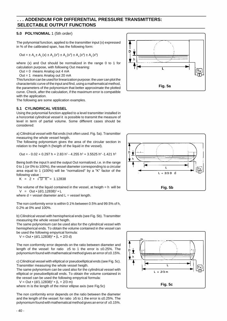
- 40 -
. . . ADDENDUM FOR DIFFERENTIAL PRESSURE TRANSMITTERS:SELECTABLE OUTPUT FUNCTIONS
5.0 POLYNOMIAL 1 (5th order)
The polynomial function, applied to the transmitter input (x) expressedin % of the calibrated span, has the following form:
Out = ± A0 ± A1 (x) ± A2 (x2) ± A3 (x
3) ± A4 (x4) ± A5 (x
5)
where (x) and Out should be normalized in the range 0 to 1 forcalculation purpose, with following Out meaning: Out = 0 means Analog out 4 mA Out = 1 means Analog out 20 mAThis function can be used for linearization purpose: the user can plot thecharacteristic curve of the input and find, using a mathematical method,the parameters of the polynomium that better approximate the plottedcurve. Check, after the calculation, if the maximum error is compatiblewith the application.The following are some application examples.
5.1 CYLINDRICAL VESSELUsing the polynomial function applied to a level transmitter installed ina horizontal cylindrical vessel it is possible to transmit the measure oflevel in term of partial volume. Some different cases should beconsidered:
a) Cilindrical vessel with flat ends (not often used. Fig. 5a). Transmittermeasuring the whole vessel heigth.The following polynomium gives the area of the circular section inrelation to the heigth h (heigth of the liquid in the vessel).
Out = - 0.02 + 0.297 h + 2.83 h2 - 4.255 h3 + 3.5525 h4 -1.421 h5
Being both the input h and the output Out normalized, i.e. in the range0 to 1 (or 0% to 100%), the vessel diameter corresponding to a circulararea equal to 1 (100%) will be "normalized" by a "K" factor of thefollowing value : K = 2 • √ 1/ π = 1.12838
The volume of the liquid contained in the vessel, at heigth = h will be V = Out • (d/1.12838)2 • Lwhere d = vessel diameter and L = vessel length.
The non conformity error is within 0.1% between 0.5% and 99.5% of h,0.2% at 0% and 100%.
b) Cilindrical vessel with hemispherical ends (see Fig. 5b). Transmittermeasuring the whole vessel heigth.The same polynomium can be used also for the cylindrical vessel withhemispherical ends. To obtain the volume contained in the vessel canbe used the following empyrical formula: V = Out • (d/1.12838)2 • (L + 2/3 d)
The non conformity error depends on the ratio between diameter andlength of the vessel: for ratio ≥5 to 1 the error is ≤0.25%. Thepolynomium found with mathematical method gives an error of ±0.15%.
c) Cilindrical vessel with elliptical or pseudoelliptical ends (see Fig. 5c).Transmitter measuring the whole vessel heigth.The same polynomium can be used also for the cylindrical vessel withelliptical or pseudoellipticall ends. To obtain the volume contained inthe vessel can be used the following empyrical formula: V = Out • (d/1.12838)2 • (L + 2/3 m)where m is the length of the minor ellipse axis (see Fig.5c)
The non conformity error depends on the ratio between the diameterand the length of the vessel: for ratio ≥5 to 1 the error is ≤0.25%. Thepolynomium found with mathematical method gives an error of ±0.15%.
Fig. 5a
Fig. 5c
Fig. 5b
d

- 41 -
. . . ADDENDUM FOR DIFFERENTIAL PRESSURE TRANSMITTERS:SELECTABLE OUTPUT FUNCTIONS
Fig. 5d
Fig. 6a
5.2 SPHERICAL TANK
Spherical tank (see Fig.5d). Transmitter measuring the whole vesselheight.
The following polynomium gives the volume of the spherical section inrelation to the heigth h of the liquid in the tank. Out = 3 h2 - 2 h3
This formula is geometrical and then his conformity is perfect.
Being both the input h and the output Out normalized, i.e. in the range0 to 1 (or 0% to 100%), the sphere diameter D corresponding to avolume equal to 1 (100%) will be "normalized" by a "K" factor of thefollowing value:
K = 2 • 3 √ 3/ (4 π) = 1.2407
The volume of the liquid contained in the tank, at heigth = h will beV = Out • (D/1.2407)3
where D = sphere diameter .
5.3 CYLINDRICAL VESSEL AND SPHERICAL TANK WITHPARTIAL LEVEL MEASUREMENT
Cases a) to d) but with partial level measurement (Fig. 6a)In these cases two methods can be used:
1) Plot the changes in volume in relation to the level changes and,using a mathematical method, find the relevant polynomium.
2) Use the polynomium coefficients for cases a) to d) and calibrate thetransmitter range to cover the full diameter of the vessel or tank: thechanges in volume for the h changes between h0 and h max will becorrect. Of course the transmitter will transmit, when the level is≤h0, the volume corresponding to h0: the same apply for level ≥hmax.All transmitted volumes are % of the total volume of the vessel.
If it is required the partial volume starting from h0 (i.e. the volume at h0 = 0) then the A0 coefficient should be equal to the polynomiumsolved for h0 with negative sign: for example for h0 = 20%
A0 = - 0.02 + 0.297 • 0.2 + 2.83 • 0.22 - 4.255 • 0.23 + 3.5525 • 0.24 -1.421 • 0.25 = - 0.14179
The polynomium coefficients for the example will be:
A0 A1 A2 A3 A4 A5
Out = - 0.14179 + 0.297 h + 2.83 h2 - 4.255 h3 + 3.5525 h4 -1.421 h5
Note : The accuracy of all above numerical values can not be guaranteed.
General notes for level measurementThe level transmitter calibration is effected by the transmitter installation conditions, i.e. if the reference connection isempty (dry leg) or liquid filled (wet leg). In the first case (dry leg) the calibration in affected by the specific gravity of themeasured liquid and the atmosphere above the liquid at process condition, whereas in the second case (wet leg), it isaffected by the specific gravity of the liquid in the connecting pipe(s).

- 42 -
. . . ADDENDUM FOR DIFFERENTIAL PRESSURE TRANSMITTERS:SELECTABLE OUTPUT FUNCTIONS
6.0 POLYNOMIAL 2 (Two polinomial functions of 2nd order) -
Analog Output transfer function can also be defined as a two polinomialfunction. Both polinomials are of 2nd order. So two different polinomialfunctions are used: Out = [± A0 +A1 (x
1) ± A2 (x2)] + [± B0 +B1 (x
1) ± B2 (x2)]
Here the polinomial with A coefficients is used for X from 0 to a K value,and the second one with B coefficients for X greater than the K value.
Ax and Bx terms of the polinomials have to be calculated according tothe shape of the vessel.A PC based software tool is available for polinomial coefficientsdefinition.
7.0 CONSTANT CURRENT
This output function, activated by a Configuration Tool, can be used totest the transmitter output, the integrity of the transmission loop and thecalibration of associated equipment like receivers, recorders, etc.When this function is activated the transmitter acts like a costant currentgenerator: using the configuration tool the user can specify a fixedoutput current of 4 mA, 20 mA or any value between 4 and 20 mA.
0 K 1
Polinomial withB coefficients
Polinomial withA coefficients
= X
Fig. 6b
TX
2nd
polin
omia
l fun
ctio
n1s
t pol
inom
ial
func
tion

- 43 -
DANGER - For installation in HazardousAreas, i.e. areas with danger of fire and/or explosion,irrespective of the protection mode used, theinstallation must carried out in accordance withlocal regulations. Ensure also that the temperatureof the transmitter does not exceed the valueindicated in the Safety Marking plate. In thisconnection, consider that process temperatureabove 85 °C (185°F) requires derating the ambientlimits by 1.5:1 ratio.
Tank
e.g. mod 621ES
Tank Nozzle
2" or 3" Tank nozzle
Extended diaphragm Flush diaphragm
2" or 3" Tank nozzle
Figure 2 - Liquid level transmitter - Diaphragm options
Figure 1 - Liquid level transmitter - Installation
Flange-mounted transmitters are suitable for open or closed tank service.The process fluid may, or may not, be corrosive, viscous, dirty and with suspended solids; each case requires a proper transmitter.600T EN Series provides a model for tank service: mod. 621ES.621ES includes two main application variants: one is dedicated to liquid level measurement and the other is marketed asdifferential pressure transmitter but it is particularly suitable for liquid level measurement.
Liquid level transmitter is mounted to a tank as shown in Figure 1.The ambient temperature of the transmitter mounting location must be between -40°C and +85°C (-40 and +185°F).The process temperature can instead be between -40°C and +320°C (-40 and +608°F). The process interface and fill fluid of thetransmitter must be selected amongst the various options provided according to the specific range of temperature.
ADDENDUM FOR FLANGE-MOUNTED TRANSMITTERS
The 621ES liquid level transmitter has been designed to connect to a flanged tank nozzle, or similar ANSI (DIN) fitting. Standardconnections for 2/3-inch Class 150/300/600 flanges, and equivalent DIN, are available.
Flush and extended diaphragm options are also available,Figure 2.The flush diaphragm is suitable for applications where theprocess is free of suspended solids.The extended diaphragm eliminates the pocket at the transmitterconnection and is typically used for slurries and viscous liquids.
It is recommended that the liquid level transmitter be mounted with the process diaphragm vertical and with the housing abovethe primary transducer as described in the pictures.Operation is not affected by mounting in other positions, however, some rezeroing may be required.The transmitter is insensitive to level changes over the lower half of the diaphragm, so it is important to locate the transmitter datumline with the center line of the tank nozzle. The nozzle also must be located so that the minimum level is always at or above thedatum line.The liquid level transmitter model 621ES can be used to measure liquid level in either open or closed (pressurized) tanks.
S
NOSSTIUCRIC
SEL
NOI
NETSOST U
RREVUOCEL
RED
RA
G
TNE'
MEF NE B EL CI
QUAT
E
ALSTIU
CRIC
I VE
H
COPEE
K
VERTIGT
E
H
WN
!
S
NOSSTIUCRIC
SEL
NOI
NETSOST U
RREVUOCEL
RED
RA
G
TNE'
MEF NE B EL CI
QUAT
E
ALSTIU
CRIC
I VE
H
COPEE
K
VERTIGT
E
H
WN
!
S
NOSSTIUCRIC
SE
L
NOI
NETSOST U
RREVUOCEL
RED
RA
G
TNE'
MEF NE B EL CI
QUAT
E
ALSTIUCRI
C
I VE
H
COPEE
K
VERTIGT
E
H
WN
!
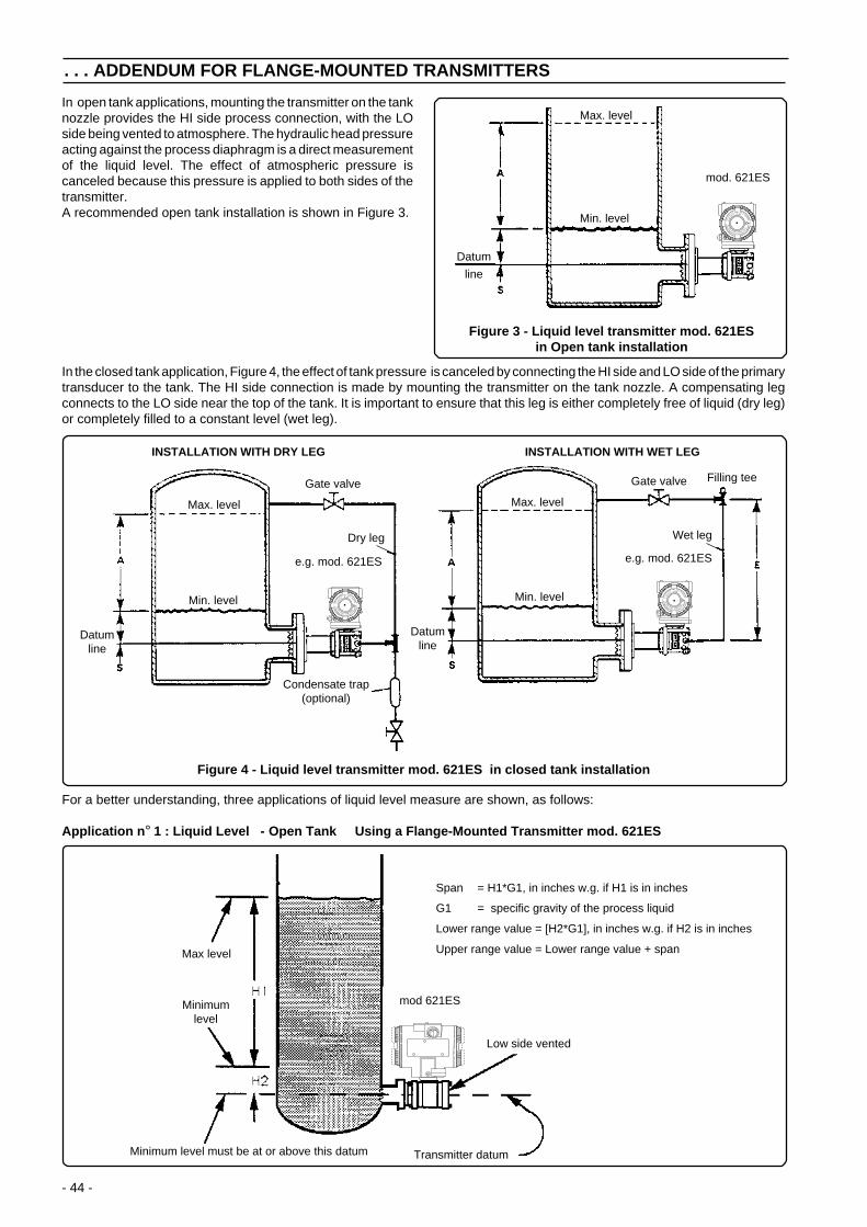
- 44 -
Max level
Minimumlevel
Low side vented
Transmitter datumMinimum level must be at or above this datum
mod 621ES
Span = H1*G1, in inches w.g. if H1 is in inches
G1 = specific gravity of the process liquid
Lower range value = [H2*G1], in inches w.g. if H2 is in inches
Upper range value = Lower range value + span
For a better understanding, three applications of liquid level measure are shown, as follows:
Application n ° 1 : Liquid Level - Open Tank Using a Flange-Mounted Transmitter mod. 621ES
Max. level
Min. level
Datumline
e.g. mod. 621ES
Dry leg
Gate valve
Condensate trap(optional)
Wet leg
Gate valve
Datumline
e.g. mod. 621ES
Min. level
Max. level
Filling tee
Figure 4 - Liquid level transmitter mod. 621ES in closed tank installation
INSTALLATION WITH DRY LEG INSTALLATION WITH WET LEG
In the closed tank application, Figure 4, the effect of tank pressure is canceled by connecting the HI side and LO side of the primarytransducer to the tank. The HI side connection is made by mounting the transmitter on the tank nozzle. A compensating legconnects to the LO side near the top of the tank. It is important to ensure that this leg is either completely free of liquid (dry leg)or completely filled to a constant level (wet leg).
In open tank applications, mounting the transmitter on the tanknozzle provides the HI side process connection, with the LOside being vented to atmosphere. The hydraulic head pressureacting against the process diaphragm is a direct measurementof the liquid level. The effect of atmospheric pressure iscanceled because this pressure is applied to both sides of thetransmitter.A recommended open tank installation is shown in Figure 3.
. . . ADDENDUM FOR FLANGE-MOUNTED TRANSMITTERS
Figure 3 - Liquid level transmitter mod. 621ESin Open tank installation
Max. level
Datum
line
Min. level
mod. 621ES
S
NOSSTIUCRIC
SEL
NOI
NETSOST U
RREVUOCEL
REDR
AG
TNE'
MEF NE B EL CI
QUAT
E
ALSTIU
CRIC
I VE
H
COPEE
K
VERTIGT
E
H
WN
!
S
NOSSTIUCRIC
SE
L
NOI
NETSOST U
RREVUOCEL
RED
RA
G
TNE'
MEF NE B EL CI
QUAT
E
ALSTIUCRI
C
I VE
H
COPEE
K
VERTIGT
E
H
WN
!
S
NOSSTIUCRIC
SEL
NOI
NETSOST U
RREVUOCEL
RED
RA
G
TNE'
MEF NE B EL CI
QUAT
E
ALSTIUCRI
C
I VE
H
COPEE
K
VERTIGT
E
H
WN
!

- 45 -
Minimumlevel
Transmitter datum
Filling tee
Impulse lines filledwith stable liquid
e.g.mod. 621ES
Max level
Minimum level must be ator above this datum
Application n ° 2 : Liquid Level - Closed Tank Using a Flange-Mounted Transmitter mod. 621ES(No Condensable Vapors)
. . . ADDENDUM FOR FLANGE-MOUNTED TRANSMITTERS
Span = H1*G1, in inches w.g. if H1 is in inches
Lower range value = [H2*G1]-[H4*Gw], in inches w.g. if H2 and H4 are in inches
Upper range value = Lower range value + span
G1 = specific gravity of process liquid
Gw = specific gravity of liquid in wet leg
Transmitter datumMinimum level must notbe below this datum
Max level
Minimumlevel
e.g.mod. 621ES
Span = H1*G1, in inches w.g. if H1 is in inches
G1 = specific gravity of the process liquid
Lower range value = [H2*G1], in inches w.g. if H2 is in inches
Upper range value = Lower range value + span
Application n ° 3 : Liquid Level - Closed Tank Using a Flange-Mounted Transmitter mod. 621ES and a Wet Leg (With Condensable Vapors)

- 46 -
. . . ADDENDUM FOR FLANGE-MOUNTED TRANSMITTERS
Blind flangeL
39 (1.54)
25 (0.98)
Low sideflange option
Mountingflange
Note: dimensions are expressed in mm. (Between parenthesis the same dimensions expressed in inches).
Certificationlabel
Identification tagAdjustments
Terminalside
Electronicside
Integraldisplayhousing
Min. clearanceto removethe cover
Output meterhousingDrain/vent
Valve
Barrel typehousing
Electricalconnections
71 (2.80)F G
BA
126 (4.96)
135
(5.3
1)
127 (5.00)17
(0.67)26
(1.02)17
(0.67)36
(1.42)
+
Processconnection
S
NOSSTIUCRIC
SEL
NOI
NETSOST U
RREVUOCEL
RED
RA
G
TNE'
MEF NE B EL CI
QUAT
E
ALSTIU
CRIC
I VE
H
COPEE
K
VERTIGT
E
H
WN
!86 (3.39)
AC
D
E
2in ANSI CL 1502in ANSI CL 3002in ANSI CL 6002in ANSI CL 9003in ANSI CL 1503in ANSI CL 3003in ANSI CL 6003in ANSI CL 9004in ANSI CL 1504in ANSI CL 300DN50 DIN ND16DN50 DIN ND40DN50 DIN ND64DN50 DIN ND100DN50 DIN ND160DN80 DIN ND16DN80 DIN ND40DN80 DIN ND64DN80 DIN ND100DN80 DIN ND160DN100 DIN ND16DN100 DIN ND40
DIMENSIONS mm (in)
SIZE/RATING
4888488888444448888888
N° OFHOLESGA (dia)
60 (2.36)60 (2.36)60 (2.36)60 (2.36)89 (3.5)89 (3.5)89 (3.5)89 (3.5)89 (3.5)89 (3.5)60 (2.36)60 (2.36)60 (2.36)60 (2.36)60 (2.36)89 (3.5)89 (3.5)89 (3.5)89 (3.5)89 (3.5)89 (3.5)89 (3.5)
92.1 (3.62)92.1 (3.62)92.1 (3.62)92.1 (3.62)127 (5)127 (5)127 (5)127 (5)157.2 (6.2)157.2 (6.2)102 (4.02)102 (4.02)102 (4.02)102 (4.02)102 (4.02)138 (5.43)138 (5.43)138 (5.43)138 (5.43)138 (5.43)158 (6.22)162 (6.38)
B (dia)
120.5 (4.74)127 (5)127 (5)165 (6.5)152.5 (6)168.5 (6.63)168.5 (6.63)190.5 (7.5)190.5 (7.5)200.2 (7.88)125 (4.92)125 (4.92)135 (5.31145 (5.71)145 (5.71)160 (6.3)160 (6.3)170 (6.7)180 (7.08)180 (7.08)180 (7.08)190 (7.48)
C (dia) D (dia)
152.5 (6)165 (6.5)165 (6.5)216 (8.5)190.5 (7.5)210 (8.26)210 (8.26)241 (9.48)228.6 (9)254 (10)165 (6.5)165 (6.5)180 (7.08)195 (7.67)195 (7.67)200 (7.87)200 (7.87)215 (8.46)230 (9.05)230 (9.05)220 (8.66)235 (9.25)
20 (0.79)20 (0.79)20 (0.79)26 (1.02)20 (0.79)22 (0.86)22 (0.86)26 (1.02)20 (0.79)22 (0.86)18 (0.71)18 (0.71)22 (0.86)26 (1.02)26 (1.02)18 (0.71)18 (0.71)22 (0.86)26 (1.02)26 (1.02)18 (0.71)22 (0.86)
E (dia)
19.5 (0.77)22.5 (0.88)25.5 (1)38.5 (1.51)24 (0.94)28.5 (1.12)32 (1.26)38.5 (1.51)24 (0.94)32 (1.26)20 (0.79)20 (0.79)26 (1.02)28 (1.1)30 (1.18)20 (0.79)24 (0.94)28 (1.1)32 (1.26)36 (1.42)20 (0.79)24 (0.94)
F
9.5 (0.37)9.5 (0.37)9.5 (0.37)9.5 (0.37)9.5 (0.37)9.5 (0.37)9.5 (0.37)9.5 (0.37)9.5 (0.37)9.5 (0.37)9.5 (0.37)9.5 (0.37)9.5 (0.37)9.5 (0.37)9.5 (0.37)9.5 (0.37)9.5 (0.37)9.5 (0.37)9.5 (0.37)9.5 (0.37)9.5 (0.37)9.5 (0.37)
flush extended
48 (1.9)48 (1.9)NANA72 (2.83)72 (2.83)NANA94 (3.7)94 (3.7)48 (1.9)48 (1.9)NANANA72 (2.83)72 (2.83)NANANA94 (3.7)94 (3.7)

- 47 -
Sensor trimmingIf a sensor trimming operation is requested for mod. 621ES level transmitter, follow the relevant procedure of the Hand HeldCommunicator and PC Software instructions.If the result is not satisfactory after having carried out either the ZERO TRIMMING or the FULL TRIMMING, the operation mustbe repeated with a special variation for these transmitters.This special procedure dedicated to the model 621ES level transmitter, is as follows:
a) LOW TRIM (low value) for FULL TRIM operation, or ZERO TRIM, only.A standard operation must be performed according to the procedure. If the result is not satisfactory the operation must berepeated with a similar procedure but with a new value which has to be entered. This value must be calculated, as follows,taking in consideration the error with reversed sign:
new V entered = V applied - ( V displayed - V applied)* (*) error
- 1st Example: Trimming at 10 mbar (applied value)If the displayed value (via HART) after the first operation, is 10.2 mbar, then the error is +0.2 (10.2 - 10).The new value to be therefore entered is 9.8 mbar (10 - 0.2).
- 2nd Example: Trimming at true zero (0 mbar)If the displayed value (via HART) after the first operation, is -0.5 mbar, the operation must be repeated entering + 0.5 mbar.
Note: The LOW TRIM and ZERO TRIM operations affect the span as they do not change the upperrange value previously set. So a high trimming operation according to point b, is highly recommended.
b) HIGH TRIM (high value) for FULL TRIM operation.A standard operation must be performed according to the procedure. If the result is not satisfactory the operation must berepeated with a procedure similar to that shown at point a above.(new calculated value with error taken with reversed sign).
Output % RerangingSometimes, in case of tank level measurement, it becomes difficult to calculate the LRV or the URV of the transmitter, or to emptythe tank for zero adjustment. So, not only with flange-mounted, but also with differential pressure transmitters using remote seals,the Output % Reranging operation helps the user during transmitter calibration.When it is know the level of the tank, expressed in percentage, the liquid level, it is possible to input this percentage thatautomatically the transmitter recalculates its LRV and URV according to the new percentage value.This can be done using a HART configuration tool on a 600T EN Transmitter, in Analog + HART version.Two options are available as Output % Reranging operation:1) OP Range Low where both LRV and URV are adjusted2) OP Range High where only URV is change in accordance with the new input percentage
As example:
. . . ADDENDUM FOR FLANGE-MOUNTED TRANSMITTERS
Actual level measured by the transmitter:Transmitter output = 27%Calibration : LRV = -125 mbar
URV = +340 mbar
a) New input level measurement (Option 1) = 30%New calibration : LRV = -139.5 mbar
URV = +325.5 mbarThe transmitter output is now = 30%
Starting again from the initial settings:Transmitter output = 27%Calibration : LRV = -125 mbar
URV = +340 mbar
b) New input level measurement (Option 2) = 30%New calibration : LRV = -125 mbar
URV = +291.5 mbarThe transmitter output is now = 30%
+

- 48 -
. . . ADDENDUM FOR FLANGE-MOUNTED TRANSMITTERS
Model 621ES differential transmitterThis model, as already said, is suitable for liquid level measurement.The fluid, in this case, must be clean, free of solids and not viscous. This because the process diaphragm is recessed as regardsthe flange face.The model 621ES differential transmitter has been designed to connect to a flanged tank nozzle, or similar ANSI (DIN) fitting.Standard connections for 2/3-inch Class 150/300, and equivalent DIN, are available (see Figures 1 and 2).This model is specifically dedicated to closed (pressurized) tanks (see Figure 4 and Applications n°2 and n°3).Mounting recommendations are like those of model 621ES level transmitter.
Adjustments Identification tag
Certificationlabel
Integraldisplayhousing
Electronicside
Output meterhousing
Terminalside
Min. clearanceto removethe cover
Drain/ventvalve
Coverslockingscrew
Electrical connections
Mountingflange
Flange/adapter
127 (5.00)17
(0.67)26
(1.02)17
(0.67)36
(1.42)
A
C
D
E
71 (2.80)
27 (1.06)
135
(5.3
1)
S
NOSSTIUCRIC
SEL
NOI
NETSOST U
RREVUOCEL
RED
RA
G
TNE'
MEF NE B EL CI
QUAT
E
ALSTIUCRI
C
I VE
H
COPEE
K
VERTIGT
E
H
WN
!
86 (3.39)
+
59 (2.32)
F
G
B
Processconnection
RATING F G
2"3"2"3"
DN 50DN 80DN 50DN 80
1.6 (0.07)1.6 (0.07)1.6 (0.07)1.6 (0.07)3 (0.12)2 (0.08)3 (0.12)2 (0.08)
19.5 (0.77)24 (0.94)22.5 (0.89)28.5 (1.12)20 (0.79)20 (0.79)20 (0.79)24 (0.94)
BA
92 (3.62)127 (5.0)92 (3.62)127 (5.0)102 (4.02)138 (5.43)102 (4.02)138 (5.43)
53 (2.09)77 (3.04)53 (2.09)77 (3.04)53 (2.09)77 (3.04)53 (2.09)77 (3.04)
ED
20 (0.79)20 (0.79)20 (0.79)22 (0.86)18 (0.71)18 (0.71)18 (0.71)18 (0.71)
152.5 (6.0)190.5 (7.5)165 (6.50)210 (8.26)165 (6.50)200 (7.87)165 (6.50)200 (7.87)
120.6 (4.75)152.4 (6.0)127 (5.0)168.5 (6.63)125 (4.92)160 (6.30)125 (4.92)160 (6.30)
CNo.ofholes
44884848
SIZE
ANSI 150 R.F.ANSI 150 R.F.ANSI 300 R.F.ANSI 300 R.F.DIN ND 16 FORM CDIN ND 16 FORM CDIN ND 40 FORM CDIN ND 40 FORM C

- 49 -
ADDENDUM FOR "EX SAFETY" ASPECTS AND "IP" PROTECTION (EUROPE)
According to ATEX Directive (European Directive 94/9/EC of 23 March 1994) and relative European Standards which canassure compliance with Essential Safety Requirements, i.e., EN 50014 (General requirements) EN 50018 (Flameproof enclosures“d”) EN 50020 (Intrinsic safety “i”) EN 50284 (Equipments, group II, category 1G), the pressure transmitters of the 600T ENSERIES have been certified for the following group, categories, media of dangerous atmosphere, temperature classes, typesof protection. Examples of application are also shown below by simple sketches.
a) Certificate ATEX II 1G, EEx ia IIC T5 (-40°C ≤ Ta ≤+40°C) EEx ia IIC T4 (-40°C ≤ Ta ≤+85°C)
TUV Certificate number Ex 50012 42206 001.The meaning of ATEX code is as follows:
II : Group for surface areas (not mines)1 : CategoryG : Gas (dangerous media)(Note: the number close to the CE marking of the transmitter safety label identifies the Notified Body whichcarries out the surveillance for the production of the transmitter)
The other marking refers to the protection type used according to relevant EN standards:EEx ia : Intrinsic safety, protection level “a”IIC : Gas groupT5 : Temperature class of the transmitter (which corresponds to 100°C max)
with a Ta (ambient temperature) +40°CT4 : Temperature class of the transmitter (which corresponds to 135°C max)
with a Ta (ambient temperature) +85°CAbout the applications, this transmitter can be used in “Zone 0” (Gas) classified area (continuous hazard) as it is shown on thefollowing sketch:
+
Zone "0"
600T EN Txcategory 1G
(EEx ia)
dangerousmedium
(process)
Tank
Application with Gas

- 50 -
. . . ADDENDUM FOR "EX SAFETY" ASPECTS AND "IP" PROTECTION (EUROPE)
b) Certificate ATEX II 1/2 G DT80°C, EEx d IIC T6 (-40°C ≤ Ta ≤+70°C) DT95°C, EEx d IIC T5 (-40°C ≤ Ta ≤+85°C)
CESI Certificate number CESI 00ATEX 035The meaning of ATEX code is as follows:
II : Group for surface areas (not mines)1/2 : Category - It means that only a part of the transmitter complies with category 1 and a
second part complies with category 2 (see next application sketch)G : Gas (dangerous media)D : Dust (dangerous media)T80°C: Maximum surface temperature of the transmitter enclosure with a Ta (ambient temperature) +70°C
for Dust (not Gas) with a dust layer up to 50 mm depth.T95°C: As before for Dust for a Ta +85°C
Note: the number close to the CE marking of the transmitter safety label identifies the Notified Body which carriesout the Surveillance for the production of the transmitter.
The other marking refers to the protection type used according to relevant EN Standards:EEx d:FlameproofIIC : Gas groupT6 : Temperature class of the transmitter (which corresponds to 85°C max) with a Ta (ambient temperature) +70°CT5 : Temperature class of the transmitter (which corresponds to 100°C max) with a Ta (ambient temperature) +85°C
About the applications, this transmitter can be used in Zone “0” (Gas) classified areas (continuous hazard) with its “processpart” only, whereas the remaining part of the transmitter, i.e. its enclosure, can be used in Zone 1 (Gas), only (see sketchbelow). Reason of this is the process part of the transmitter (normally called primary transducer) that provides inside separationelements to seal off the electrical sensor from the continuously hazardous process, according to the EN50284 and EN50018.About Dust application, the transmitter is suitable for "Zone 21" according to the EN 50281 as it is shown on the relevant part ofthe sketch:
IP code)About the degree of protection provided by the enclosure of the pressure transmitter, the 600T EN SERIES has been certified IP67according to EN 60529 standard (this is equivalent to IEC 529).The first characteristic numeral indicates the protection of the inside electronics against ingress of solid forein objects includingdusts. The assigned “6” means an enclosure dust-tight (no ingress of dust).The second characteristic numeral indicates the protection of the inside electronics against ingress of water. The assigned “7”means an enclosure water-protected against a temporary immersion in water under standardized conditions of pressure and time.
+
Zone "0"
dangerousmedium
(process)
Tank600T EN Txcategory
1/2G (EEx d)
Zone 0 / Zone 1Separationelements
Zone "1"
primarytransducer
Zone "20"
dangerousmedium
(process)
Silo600T EN Tx
category1/2D (EEx d)
(IP6x)
Zone "21"
Application with Gas Application with Dust
+

- 51 -
PRODUCTS & CUSTOMER SUPPORT
A Comprehensive Instrumentation Range
Analytical Instrumentation• Transmitters
On-line pH, conductivity, and dissolved oxygentransmitters and associated sensing systems.
• SensorspH, redox, selective ion, conductivity and dissolvedoxygen.
• Laboratory InstrumentationpH and dissolved oxygen meters and associatedsensors.
• Water AnalyzersFor water quality monitoring in environmental, powergeneration and general industrial applications including:pH, conductivity, ammonia, nitrate, phosphate, silica,sodium, chloride, fluoride, dissolved oxygen andhydrazine.
• Gas AnalyzersZirconia, katharometers, hydrogen purity and purge-gasmonitors, thermal conductivity.
Controllers & Recorders• Controllers
Digital display, electronic, pneumatic. Discrete single-loop and multi-loop controllers which can be linked to acommon display station, process computer or personalcomputer.
• RecordersCircular and strip-chart types (single and multi-point) fortemperature, pressure, flow and many other processmeasurements.
Electronic Transmitters• Smart & Analog Transmitters
For draft, differential, gauge and absolute pressuremeasurement. Also, liquid level and temperature.
• I to P Converters and Field Indicators
Flow Metering• Magnetic Flowmeters
Electromagnetic, insertion type probes and watermeters.
• Turbine Flowmeters
• Wedge Flow Elements
• Mass Flow MetersTransmitters, sensors, controllers and batch/displayunits.
Level Control• Submersible, Capacitance & Conductivity.
Pneumatic Instrumentation• Transmitters
• Indicating Controllers
• Recording Controllers
Customer Support
ABB Instrumentation provides a comprehensive after salesservice via a Worldwide Service Organization. Contact one ofthe following offices for details on your nearest Service andRepair Centre.
ItalyABB Instrumentation SpATel: +39 (0) 344 58111Fax: +39 (0) 344 56278
United KingdomABB LtdTel: +44 (0)1480 475321Fax: +44 (0)1480 217948
United States of AmericaABB Inc.Tel: +1 215-674-6000Fax: +1 215-674-7183
Client Warranty
Prior to installation, the equipment referred to in this manualmust be stored in a clean, dry environment, in accordance withthe Company's published specification. Periodic checks must bemade on the equipment's condition.
In the event of a failure under warranty, the followingdocumentation must be provided as substantiation:
1. A listing evidencing process operation and alarm logs at timeof failure.
2. Copies of operating and maintenance records relating to thealleged faulty unit.

- 52 -

- 53 -

- 54 -

- 55 -
EC DECLARATION OF CONFORMITY
We: ABB Instrumentation SpaVia Statale, 11322016 Lenno (Como)Italy
declares under our sole responsibility that the products:
600T EN Series (Transmitters, Hand Held Terminal, FieldIndicator) in all the communication configurations (4÷20 mA +
HART®, Profibus, FOUNDATION Fieldbus, Safety)
are in conformity with the following standards:
EN 50 081-1 (1992) Electromagnetic compatibility - Genericemission standard - Residential, commercialand light industry
according to: EN55022 (1995)
EN 50 082-2 (1995) Electromagnetic compatibility - Genericimmunity standard - Industrial environment
according to: EN61000-4-2 (1998)EN61000-4-3 (1998)EN61000-4-4 (1995)EN61000-4-5 (1995)ENV50141 (1993)
following the provisions of the EMC Directives 89/336/EEC and93/68/EEC.
Lenno, October 10, 2001 ABB Instrumentation Spa Technical Manager
A. Moroni

- 56 -
IM/6
00T
EN
_S
Rev
1
The Company's policy is one of continuous productimprovement and the right is reserved to modify thespecifications contained herein without notice.
ABB Instrumentation spaVia Statale 11322016 Lenno (Como)ItaliaTel (0344) 58111Fax (0344) 56278
ABB Ltd.Howard RoadSt. Neots, Cambs.Englang PE19 3EUTel. (01480) 475321Fax (01480) 217948
ABB Inc.125 East County Line RoadWarminster PA18974 USATel. (215) 674-6000Fax (215) 674-7183