Operating Instruction - ESPA Pumps UK · AUC3400 control strategy . Example diagram for 3 pumps...
157
Reference guide Reference guide Version 4.0 Version 4.0 A A U U C C 3 3 4 4 0 0 0 0
Transcript of Operating Instruction - ESPA Pumps UK · AUC3400 control strategy . Example diagram for 3 pumps...

Reference guide Reference guide
Version 4.0 Version 4.0
AAUUCC33440000

RRReeefffeeerrreeennnccceee ggguuuiiidddeee
Version 4.0

Page 3 of 157
Index
1 INTRODUCTION........................................................................................................................8
2 AUC3400 CONTROL STRATEGY.............................................................................................9
3 AUC3400 FRONT & BACK VIEW ...........................................................................................10
4 AUC3400 TECHNICAL SPECIFICATIONS .............................................................................11
5 AUC3400 TERMINAL CONNECTIONS...................................................................................12
6 AUC3400 CONTROL OPTIONS..............................................................................................13
7 AUC3400 COMMUNICATION OPTIONS ................................................................................15
8 AUC3400 CONTROL FEATURES...........................................................................................16
9 AUC3400 FUZZY WISE CONTROL ........................................................................................19
10 AUC3400 HMI (HUMAN MACHINE INTERFACE) ...............................................................21
11 AUC3400 PC PROGRAM.....................................................................................................22
11.1 Security password..............................................................................................................................................25
11.2 Setting up a connection to the local AUC3400 ................................................................................................26
11.3 Downloading the alarm history .........................................................................................................................27
11.4 Saving the current HMI display to file...............................................................................................................28
11.5 Documentation....................................................................................................................................................30
12 AUC3400 DISPLAY STRUCTURE.......................................................................................34
13 AUC3400 HEAD UP DISPLAYS ..........................................................................................35
13.1 The default head up display ..............................................................................................................................36
14 AUC3400 QUICK SETUP.....................................................................................................37

15 AUC3400 MENU...................................................................................................................37
15.1 Status ...................................................................................................................................................................38 15.1.1 Start conditions .............................................................................................................................................39 15.1.2 Pumps and drives .........................................................................................................................................39
15.1.2.1 Main pumps ..........................................................................................................................................40 15.1.2.2 Pre-pressure pumps .............................................................................................................................40 15.1.2.3 Jockey pump.........................................................................................................................................41 15.1.2.4 Hz, Amp’s and kW’s..............................................................................................................................41 15.1.2.5 Running hours.......................................................................................................................................41
15.1.2.5.1.1 Main total hours...........................................................................................................................42 15.1.2.5.2 Main periodical hours.........................................................................................................................42 15.1.2.5.3 Pre-press total hours..........................................................................................................................42 15.1.2.5.4 Pre-press periodical hours .................................................................................................................42 15.1.2.5.5 Jockey pump (DOL) ...........................................................................................................................43 15.1.2.5.6 Reset period.......................................................................................................................................43
15.1.2.6 FC drives status ....................................................................................................................................43 15.1.3 Main pump sequence....................................................................................................................................44 15.1.4 Pre-pressure pump sequence ......................................................................................................................45 15.1.5 Pressure........................................................................................................................................................46 15.1.6 Flow...............................................................................................................................................................46
15.1.6.1 Flow readings........................................................................................................................................46 15.1.6.2 Reset period..........................................................................................................................................47
15.1.7 Virtual flow ....................................................................................................................................................47 15.1.8 Setpoint.........................................................................................................................................................47 15.1.9 Power consumption ......................................................................................................................................48
15.1.9.1 Readings...............................................................................................................................................48 15.1.9.2 Reset period..........................................................................................................................................48
15.2 Alarms..................................................................................................................................................................49 15.2.1 Actual alarms ................................................................................................................................................49 15.2.2 Alarm overview .............................................................................................................................................51 15.2.3 History...........................................................................................................................................................53 15.2.4 Erase history .................................................................................................................................................53 15.2.5 Download history PC ....................................................................................................................................54 15.2.6 Enable alarm SMS........................................................................................................................................54
15.3 Events ..................................................................................................................................................................56 15.3.1 Event History.................................................................................................................................................57 15.3.2 Erase history .................................................................................................................................................58 15.3.3 Download history PC ....................................................................................................................................58
15.4 Control modes.....................................................................................................................................................58 15.4.1 Main pumps ..................................................................................................................................................59 15.4.2 Pre-pressure pumps .....................................................................................................................................60 15.4.3 Jockey pump (DOL) ......................................................................................................................................60
15.5 Pump sequence ..................................................................................................................................................62 15.5.1 Main pumps ..................................................................................................................................................62
15.5.1.1 Manual pump change ...........................................................................................................................62 15.5.1.2 Hourly pump change.............................................................................................................................65 15.5.1.3 Sequence status ...................................................................................................................................65
15.5.2 Pre-pressure pumps .....................................................................................................................................66
Page 4 of 157
15.5.2.1 Manual pump change ...........................................................................................................................66

15.5.2.2 Sequence status ...................................................................................................................................66 15.5.2.3 Link to main pumps...............................................................................................................................67
15.6 Pump / tank test ..................................................................................................................................................68 15.6.1 Pump test run................................................................................................................................................68 15.6.2 Expansion tank .............................................................................................................................................69 15.6.3 Pressure tank test .........................................................................................................................................69 15.6.4 Leak detection...............................................................................................................................................70
15.7 Setpoints..............................................................................................................................................................72 15.7.1 Week program ..............................................................................................................................................73
15.7.1.1 Adding entry..........................................................................................................................................74 15.7.1.2 Changing entry......................................................................................................................................76 15.7.1.3 Deleting entry........................................................................................................................................76
15.7.2 Local setpoints ..............................................................................................................................................77 15.7.2.1 Local setpoint 1 to 5..............................................................................................................................77
15.7.3 Remote setpoint............................................................................................................................................77 15.7.4 Start up setpoint............................................................................................................................................78 15.7.5 Restart setpoint.............................................................................................................................................78 15.7.6 Fire setpoint ..................................................................................................................................................79 15.7.7 Main pumps increase....................................................................................................................................79 15.7.8 Pre-pressure pumps increase.......................................................................................................................79 15.7.9 Setpoint ramp................................................................................................................................................81 15.7.10 Flow limitation ...............................................................................................................................................82 15.7.11 Jockey pump (DOL) ......................................................................................................................................83
15.8 Zero flow detection.............................................................................................................................................84 15.8.1 Enable...........................................................................................................................................................84 15.8.2 Boost level ....................................................................................................................................................86 15.8.3 Detection speed ............................................................................................................................................87 15.8.4 Zero flow timers ............................................................................................................................................87 15.8.5 Low flow stop ................................................................................................................................................88 15.8.6 Low speed stop.............................................................................................................................................88
15.9 Clock menu..........................................................................................................................................................89 15.9.1 Read clock ....................................................................................................................................................89 15.9.2 Set clock .......................................................................................................................................................89
15.10 Configuration ..................................................................................................................................................90 15.10.1 Pumps...........................................................................................................................................................90
15.10.1.1 Pump application ..................................................................................................................................91 15.10.1.2 Main pumps ..........................................................................................................................................91 15.10.1.3 Main pumps curve.................................................................................................................................93 15.10.1.4 Jockey curve (FC).................................................................................................................................94 15.10.1.5 Pre-pressure pumps .............................................................................................................................96 15.10.1.6 Pre-pressure setup ...............................................................................................................................96
15.10.1.6.1 Requirement table............................................................................................................................97 15.10.1.6.2 Setpoint increase .............................................................................................................................97 15.10.1.6.3 Timeout failure..................................................................................................................................98 15.10.1.6.4 Main pump delay..............................................................................................................................98 15.10.1.6.5 Low water detection .........................................................................................................................98 15.10.1.6.6 AUTO switches.................................................................................................................................99
15.10.1.7 DOL Jockey pump ..............................................................................................................................100 15.10.1.8 Delay for lead pump............................................................................................................................100
Page 5 of 157
15.10.1.9 Run on pump timers............................................................................................................................101

15.10.2 Frequency converters .................................................................................................................................102 15.10.2.1 Setup motor data ................................................................................................................................102
15.10.2.1.1 Motor 1 ...........................................................................................................................................102 15.10.2.1.2 Copy 1 to others.............................................................................................................................103 15.10.2.1.3 Motor 2 ...........................................................................................................................................103 15.10.2.1.4 Motor 3 ...........................................................................................................................................103 15.10.2.1.5 Motor 4 ...........................................................................................................................................104 15.10.2.1.6 Motor 5 ...........................................................................................................................................104 15.10.2.1.7 Motor 6 ...........................................................................................................................................104 15.10.2.1.8 Motor 7 ...........................................................................................................................................105 15.10.2.1.9 Motor 8 ...........................................................................................................................................105
15.10.2.2 Program FC ........................................................................................................................................105 15.10.3 Sensors.......................................................................................................................................................107
15.10.3.1 Discharge pressure.............................................................................................................................107 15.10.3.1.1 Sensor range..................................................................................................................................107 15.10.3.1.2 High alarm......................................................................................................................................108 15.10.3.1.3 High alarm reset .............................................................................................................................108 15.10.3.1.4 Low alarm.......................................................................................................................................108 15.10.3.1.5 Low alarm reset..............................................................................................................................109 15.10.3.1.6 Low alarm override.........................................................................................................................109 15.10.3.1.7 High alarm switch...........................................................................................................................109
15.10.3.2 Suction pressure .................................................................................................................................110 15.10.3.2.1 Enable ............................................................................................................................................110 15.10.3.2.2 Sensor range..................................................................................................................................110 15.10.3.2.3 Low alarm.......................................................................................................................................111 15.10.3.2.4 Low alarm reset..............................................................................................................................111 15.10.3.2.5 Low alarm override.........................................................................................................................111 15.10.3.2.6 Low alarm switch............................................................................................................................112
15.10.3.3 Remote setpoint..................................................................................................................................112 15.10.3.3.1 Enable ............................................................................................................................................113 15.10.3.3.2 Range.............................................................................................................................................113
15.10.3.4 Flow.....................................................................................................................................................113 15.10.3.4.1 Analogue flow meter ......................................................................................................................114 15.10.3.4.2 Pulse flow meter.............................................................................................................................114 15.10.3.4.3 Virtual flow......................................................................................................................................114
15.10.3.4.3.1 Record pump curve .................................................................................................................115 15.10.3.4.3.2 Pump curve points...................................................................................................................115 15.10.3.4.3.3 Show real/virtual ......................................................................................................................117
15.10.3.4.4 Pumped volume .............................................................................................................................118 15.10.3.4.5 Show at head up ............................................................................................................................118 15.10.3.4.6 Flow threshold ................................................................................................................................118
15.10.3.5 kWh.....................................................................................................................................................119 15.10.3.6 High water switch................................................................................................................................119
15.10.4 Controller ....................................................................................................................................................120 15.10.4.1 Sample time ........................................................................................................................................120 15.10.4.2 Control speed......................................................................................................................................120 15.10.4.3 Differentiator .......................................................................................................................................122 15.10.4.4 Minimum speed...................................................................................................................................122 15.10.4.5 Pressure filters ....................................................................................................................................123 15.10.4.6 Anti cavitation mode............................................................................................................................124
15.10.4.6.1 Anti cavitation.................................................................................................................................124 15.10.4.6.2 Anti cavitation + auto detection ......................................................................................................125 15.10.4.6.3 Anti cavitation + auto status ...........................................................................................................125
15.10.4.7 Friction losses .....................................................................................................................................126
Page 6 of 157
15.10.4.8 Pump simulator ...................................................................................................................................127

15.10.5 Modem ........................................................................................................................................................128 15.10.5.1 Modem selection.................................................................................................................................130 15.10.5.2 SMS header text .................................................................................................................................130 15.10.5.3 Total of recipients................................................................................................................................131 15.10.5.4 Recipient number 1.............................................................................................................................131 15.10.5.5 Recipient number 2.............................................................................................................................132 15.10.5.6 Recipient number 3.............................................................................................................................133 15.10.5.7 Recipient number 4.............................................................................................................................133 15.10.5.8 Recipient number 5.............................................................................................................................134 15.10.5.9 Enable alarm SMS..............................................................................................................................135 15.10.5.10 Enable call cycle .................................................................................................................................135 15.10.5.11 Initialise modem..................................................................................................................................136
15.10.6 UPS.............................................................................................................................................................136 15.10.7 Pump / tank test ..........................................................................................................................................136 15.10.8 Remote start/stop........................................................................................................................................137 15.10.9 Pump bocking .............................................................................................................................................137 15.10.10 Head up displays ....................................................................................................................................138
15.10.10.1 Head up display ..................................................................................................................................138 15.10.10.2 Show flow in head up display .............................................................................................................138 15.10.10.3 Customer text......................................................................................................................................139 15.10.10.4 Documentation....................................................................................................................................139 15.10.10.5 Reset program ....................................................................................................................................140
15.10.11 Service setting ........................................................................................................................................140 15.10.11.1 Test Timing .........................................................................................................................................141
15.11 Password .......................................................................................................................................................142 15.11.1 Log out ........................................................................................................................................................143 15.11.2 Change password .......................................................................................................................................144
16 COMMISSIONING ..............................................................................................................145
17 VLT 2800 PARAMETER SETUP........................................................................................148
18 VLT 6000 PARAMETER SETUP........................................................................................150
19 FC200 PARAMETER SETUP.............................................................................................152
20 FAQ (FREQUENTLY ASKED QUESTIONS) .....................................................................156
Page 7 of 157

1 Introduction
The AUC3400 is a pump controller that incorporates new technologies and algorithms to deliver state of the art pressure control. The main reasons for installing an AUC3400 controller in your application are:
• The AUC3400 controller will save you money and energy. That’s because pumps are running at the best efficiency. Each main pump is frequency controlled and pumps will only run when needed. The AUC3400 can calculate exactly at which speed to start and stop a pump. The AUC3400 applies a dead band around the setpoint, which allow very small pressure fluctuations, often caused by vibrations and turbulence. As a result it will not accelerate nor decelerate the pump motors unnecessary and save energy.
• The AUC3400 controller offers superior ‘Fuzzy Wise’ pressure control. The pressure is controlled in a step less, smooth way, without pressure shocks and with no overshoot.
• The AUC3400 controller offers a great price / performance ratio. The AUC300 controller is cheap, but offers a lot of functionality to deal with most commons application in pressure boosting and irrigation.
• The AUC3400 controller offers scalability. One controller to control just a single pump or up to 8 main or jockey pumps and possibly up to 8 pre-pressure pumps! Furthermore, you can purchase your control panel with a full manual control option for all of these pumps. All that is possible, due to the scalable hardware and software of the AUC3400. Hardware modules can be added and the control software comes prepared to control most of the possible combination of pumps.
• The AUC3400 controller offers remote control capabilities. There is a free PC program that will allow you to monitor and control the AUC3400 controller remotely. It let’s you manoeuvre through the menu, create trends and list alarm. Furthermore, the AUC3400 can send text SMS messages to you cell phone when there is an alarm or situation that needs attention. Vice versa you can send SMS to the AUC3400 to request a status update or to request the last 10 error messages or to acknowledge and reset alarms.
• The AUC3400 controller offers redundancy. Each individual drive can have a hand switch with potentiometer to adjust speed. When the AUC3400 fails, each drive can be operated manually, in depend of other drives.
• The AUC3400 controller saves you valuable time commissioning your application. There is a Quick Setup and Quick Commissioning menu with preset default values for all parameters. For most application it suffices to step through the Quick menus to successfully complete commissioning.
Page 8 of 157
All this will be explained in detail in this reference guide.

2 AUC3400 control strategy AUC3400 control strategy
Example diagram for 3 pumpsFlow
demandSpeed (%)
Pump 1 starts at minimum speed,
ramps up and
continues to run at 100%
1 pump
Time
3 pumps running 2 pumps 1 pump 2 pumps
Pump 3 starts at minimum speed,
ramps up and
continues to run at 100%
Pump 2 starts at minimum speed,
ramps up and
continues to run at 100%
Pump 1 ramps from 100% speed
down to minimum
speed and stops
Pump 2 ramps from 100% speed
down to minimum
speed and stops
Pump 3 ramps from 100% speed
down to minimum
speed and stops
100% speed
Minimum speed
Flow demand stable
Flow demand
increases
Flow demand
decreases
Q
H (Bar)
Pressure
1 pump running
2 pumpsrunning
3 pumpsrunning
At minimum speed and no flow a pump
can just boost the pressure
to the setpoint
Pump 1 at minimum
speed
Pump 1 at 100% speed
Pump 2 at minimum
speed
Pump 3 at minimum
speed
Pump 3 at 100% speed
Pump 2 at 100% speed
Page 9 of 157

Page 10 of 157
3 AUC3400 front & back view
Front
Back

4 AUC3400 Technical specifications Features Controller Specifications Processor Z-world Rabbit RCM3400 Flash Memory 512K SRAM 512K Backup Battery Varta CR2032 or equivalent, 3V lithium coin type. Digital Inputs 10 inputs 24VDC, low current, < 5 mA. Digital Outputs 8 relays, Maximum +230 V / 2 Amp per channel. Analogue Inputs 8 channels 12-bit res., 4 - 20 mA DC Serial Ports 1 x RS485, 1 x RS-232 Real-time Clock Yes Watchdog/Supervisor Yes Power 24V DC Operating Temperature 0° C to +50 °C Humidity 5 – 95%, non condensing Dimension 155 (H) x 255 (W) x 45 (D)
Processor
RAM Clock
FLASH
DISPLAY 4 x 20 characters
Terminals
8
RELAYS
2 Amp
with
change
over contacts
Con-trast
Battery
cell
Power supply
Fuse
Page 11 of 157

5 AUC3400 Terminal connections
Pump blocking
Fire *2
INPUTS
RS485 bus VLT (A)
RS485 bus VLT (B)
RS485 bus VLT (GND)
kWh meter pulse
Jockey pump failure
Reset
High pressure switch Dry running suction
Phase failure
Remote start / stop *1
Pressure tank test valve
Claxon
Flow meter pulse
0 VDC power
0 VDC power
24 VDC power
24 VDC (= terminal 13)
Outputs (relays) Analogue inputs
General alarm
Leak detection *3
Pre-press pump 1 *4
Pre-press pump 2 *5
Discharge pressure
Flow
Suction pressure
Remote setpoint
Spare
Spare
Spare
Remote setpoint on/off
0 VDC power
GND - Analog ground
RS232 modem (RXD)
RS232 modem (TXD)
RS232 modem (GND)
GND - Analog ground
Jockey pump *6
Flow threshold *7
24 VDC (= terminal 40)
*1 optionally this input can be programmed to signal a pressure tank switch for low air *2 optionally this input can be programmed to signal an external high water detection switch
Page 12 of 157
*3 – 8 optionally this output can be programmed to signal MGE motor 1-6 running.

6 AUC3400 control options
Page 13 of 157
Flow meter Analogue / pulses
Discharge sensor
Discharge switch
KWh meter
1 – 8 frequency controlled pumps by Danfoss series VLT 6000 or VLT 2800. Any number of these 8 available pumps can be configured to operate as main pumps, standby (spare) pumps or jockey pumps. Optionally each pump can have separate HAND-OFF-AUTO switches.
Jockey pump (DOL
control)
1 – 8 direct on line (DOL) controlled pre-pressure pumps. Optionally each pump can have separate HAND-OFF-AUTO switches.
Suction sensor
Suction switch

The AUC3400 control panel can have full manual control options. Notes
Failure lamps
Healthy lamps
Running lamps
Selector switches OFF
AUTO – HAND
Potentiometer 0-100% speed with integrated switch.
The potentiometer has to be turned to 0% speed, before the
motor can be started in manual operation
(HAND).
• The manual control options are not necessary for the operation of the pumps. The AUC3400 can be ordered without those options.
• The manual options provide a level of redundancy: if the AUC3400 fails the pumps can still be operation manually in HAND.
Page 14 of 157

7 AUC3400 communication options
Page 15 of 157
Connect a second local HMI… (APD 232)
…or a local laptop running the AUC3400 visualization program
…or a low cost GSM modem for remote connection to a PC running the
AUC3400 visualization program modem and for generating SMS text messages
on your mobile phone.
…or use your mobile phone.to send a SMS text messages TO the AUC3400. You can: -Acknoledge or reset alarms - Request the AUC3400 to send back an SMS with a status report or send up to 5 SMS messages with the most recent alarm history.
Serial Port2
RS485 Port
Read / control frequency converters
over RS485 bus
…or use a modem pool with up to 5 recipients and and alarm call cycle.

8 AUC3400 control features
Up to 8 frequency controlled pumps. Any number of these pumps can be configured to operate as main pumps, standby (spare) pumps or jockey pumps Supported drives are currently: Danfoss VLT2800, VLT600 and FC201 series.
Additionally the AUC3400 support Danfoss FCM300 motors and Grundfos MGE motors with integrated frequency converters. Up to 8 direct on line controlled pre-pressure pumps. 1 optional DOL operated jockey pump with programmable start / stop pressure levels (no external
pressure switch needed). Optional HAND-OFF-AUTO switches for each pump. We developed a special electronic print which
accommodates a switch and a potentiometer for manual adjustment of the pump speed. For safety the potentiometer knob must be turned to zero speed before manual start is effectuated. The print is wired directly to terminals of the Danfoss drives without intervention of the AUC3400. Φυζζψ ωισε control offers state of the art adaptive pressure control. Very easy to commission, only one
parameter (ramp time) is required. The control algorithm calculates required pumps speeds for starting, stopping and ramping up and down the pumps with minimum hydraulic shocks. Fast Fuzzy option. If you have the need for a slow and gentle overall control of your system, for example
in irrigation, you still need a fast reaction of the system when the flow demand is abruptly stopped (when the irrigators shut down fast). Fast fuzzy brings the solution. Danfoss and Grundfos drives are controlled by the AUC3400 over RS485 bus communication, allowing:
– Programming of the frequency converters by the AUC3400. All relevant menus are covered, no need to program the drives manually. Approximately 40 parameters in two setups for automatic and manual control are set. Programming can be done even while the pump set is in operation. – Readout of motor currents (Amps) – Readout of motor power (kW) – Readout of motor frequency (Hz) – Calculation of kWh without the need for an external kWh meter and pulse input – Update of running hours, even in manual control – Reading of all status flags (standby, ready, trip, etc.), also by remote PC/Modem. HMI (display) featuring 4 lines of 20 characters, 8 keys, power and alarm led. Optional secondary HMI. Context sensitive menu system. WYSIWYN: what you see is what you need!
Menus and information display are visible or hidden, depending on the selected hardware configuration. For example if you have selected no jockey pump, you will not be bothered by irrelevant menus, controls and status displays concerning jockey pumps. Head up displays for quick look up of status information. One customisable head up display for company name & service and call out telephone number. This
display can be locked to prevent anyone entering the menu system. Hierarchical menus for easy access to settings and intuitive manoeuvring.
Page 16 of 157
Alarms – actual alarm list directly accessible by alarm function key on HMI front. – alarm history with time and date logging (max. 99 alarms). – alarm history can be downloaded to PC program AUC3400.exe (text / Ms Excel format). – SMS messages can be transmitted by a low cost GSM serial modem (Siemens TC35i). – A modem pool with up to 5 recipients can de setup. The AUC3400 expects to receive an reset or

acknowledge SMS FROM one of the recipients after sending an alarm SMS. When no reset or acknowledge is returned, the AUC3400 will relay the alarm SMS to the next recipient in the modem pool. – General alarm relay and horn relay (comes up when new alarm rises). Event history logs pump starts, logging on and of, fire, remote starts, etc. Monthly test SMS to check the condition of the communications line. Real Time Clock with automatic summer time and winter time correction. Pump alternation through programmable and predictable (known) pump sequence scheme.
Separate alternation schemes for main, jockey and pre-pressure pumps. Pump test run (programmable). Week program (programmable) for setpoints, test runs, pump changes and flow limitations. Fire setpoint Running hours (total and periodical for all pumps). Leak detection (counts the number of starts within a given span of time and optionally shuts down the
pump set. Pressure tank test (an algorithm to determine the air pressure in the tank) Setpoint ramp timer (programmable) for smooth setpoint changes. Start up setpoint for filling pipe lines with one pump at a programmable maximum speed (prevents water
hammer and cavitation of the lead pump). Restart setpoint for delayed restart after the pumps have shut down because of zero flow. Zero flow detection with programmable pressure boost and pump shut down. Optional low speed stop and low flow stop Suction pressure:
– optional analogue input with programmable range, live zero and wire break alarm. – optional pressure switch. – low pressure / water level shut down with automatic restart. Discharge pressure:
– analogue input with programmable range, live zero and wire break alarm. – optional digital high pressure switch. – high pressure shut down with automatic restart. – low pressure shut down with adjustable start up override timer. Flow
– analogue input with programmable range, live zero and wire break alarm. – high speed pulsed rate input for cheaper flow meters (up to 500 Hz) or pumped volume – rate (m3/h) and total volume (m3). – optional digital pulse input for volume. Otherwise, the volume can be calculated from the analogue flow rate input. – total and periodical volume counters (can be reset). – Flow threshold output, activated when flow passes adjustable flow rate. – Support of bypass valve (opens and closes at preset flow rates) – Flow limitation: above a set flow the setpoint will be lowered by a set ramp to limit the water usage by end users. Per setpoint a separate flow limitation curve can be defined. Virtual Flow calculation by polynomial calculation of pump curves.
- If no flow meter is present flow can be calculated at all speeds, by either recording a pump curve, or by specifying a set of flow/pressure points, representing the pump curve. Friction loss compensation. Compensates pressure losses in the pipes by increasing the setpoint at
higher flows. kWh pulse input with totalised and periodical counters (can be reset).
Page 17 of 157
Optional low cost modem for remote access (Siemens TC35i).

Optional PC program for local or remote (trough modem) monitoring and controlling the AUC3400. The program features: – A virtual HMI identical to the local HMI – A graphical presentation of the pump set and all readings – A data logger with a real time trend window. No need to rent expensive data loggers anymore! Selectable trend pens for inlet, discharge pressure, flow, speed, number of pumps, kW, Amps, etc. – An alarm window showing all active alarms. – All readings and trend values are update at 0,5 second intervals! – A documentation option to download all menus and setting. Can be used for witness tests. – Password protection. – Direct connection to AUC3400. – Remote connection to AUC3400 over modem. – All this is still possible if the PC is a remote PC, communicating over a 9600 baud GSM modem! Password protection to prevent tampering by unauthorised personnel. Build in pump set simulator.
Supplier: when you want to simulate the AUC3400 controller in the workshop with all input options enabled you can run the build in pump set simulator. The discharge pressure input can be used to connect a 4-20 mA flow valve simulator. The AUC will control and behave as if it was controlling the pumps and pressure in reality. Possibility for parallel speed control of some or all main pumps, effectively creating one big pump. This
mode of operation can be used in cases where cavitation causes problems. Quick setup menu for commissioning (from the head up display press arrow up key). Service due reminder. If enabled, an alarm will be raised indicated that service is due. The
commissioner can specify the date at which the alarm is raised. The end customer cannot delete this alarm, only service personnel are authorized to do so.
Page 18 of 157

9 AUC3400 Fuzzy Wise control The AUC3400 features Φυζζψ ωισε control. Φυζζψ ωισε is our interpretation of the more common Fuzzy Logic (FL), and it is dedicated to pump control. Fuzzy Logic is hot these days. Born in 1965 from the works of Professor Lofti Zadeh in the University of Berkeley, these theories have gained great acceptation nowadays, especially in Japan where they are applied in all sort of things from unmanned helicopters to video cameras. Probably you’re not aware of it, but you use Fuzzy Logic technologies everyday while driving your car, watching TV or even shaving yourself in the morning! So what does it do? Without going too much into technical detail we can take an everyday problem as an example to explain how it works. Suppose you take a shower in a hotel and, no luck, there is no thermostatic tap. Just a cold water and a warm water tap. Then, how do you control the temperature? Well, you probably open the hot water tap first, waiting for warm water to come (dead lag). You adjust the amount of water to your convenience and you start mixing cold water. But you really don’t have a clue of how far to open the cold water to get the right temperature, or do you? Well you may not be aware of it, but it seems that you apply a set of rules which you may not even be aware of: • When the water is very cold, you close the cold water very fast • When the water is cold, you close the cold water more slowly • When the water is a bit cold, you close the cold water just a little bit • When the water is a bit hot, you open the cold water just a little bit • When the water is hot, you open the cold water more fast • When the water is very hot, you open the cold water very fast Just how fast fast is, or exactly how little little is, or how you select between those rules is a very personal question. Fact is, you apply those rules, and you make an adjustment to the ‘control system’ (the taps). You then wait to see the effect. And then you repeat the whole sequence all over until the temperature off the water is within an acceptable tolerance, lets say 1 degree. As long as the temperature stays within 1 degree of your ‘setpoint’ temperature you do not touch the taps. Well: this is exactly what the AUC3400 Φυζζψ ωισε controller does! Except that it can do a bit more… for it can calculate fairly well just how far to open or close the taps. In its own field of application, it can calculate the speed correction required to control to the setpoint pressure. And that is why we put the word ωισε behind Φυζζψ. We can do more than just applying a set of Fuzzy rules, called “Linguistic Variables”. We know the mathematical relation between pump speed and pressure and flow. Therefore, we can make a better ‘wise’ guess of how to adjust the speed to get where we want as fast as possible.
Page 19 of 157
So is that all there is? No, not quite. Because pressure (or temperature) control is not a one dimensional thing. You also have to address changes in pressure (or temperature).

Back to the shower; the water is cold, you close the cold water tap and you want to wait 2 seconds before you expect to make another adjustment. But guess what? Contrary to what you expected the water gets even colder while you are waiting. Then you don’t wait for 2 seconds, you start to re-adjust again, because you know that the first correction was not sufficient. This would also apply for the opposite system reaction. If you closed the cold water tap and you feel that the temperature increases must faster than you expected, you would start to re-adjust intermediately, for you know that the temperature would otherwise overshoot and you might burn your skin. So what can we conclude? Well, that there are complementary sets of rules, not just the set of rules that we listed earlier in this chapter. We also apply rules how to handle, unexpected, sudden changes in pressure (or temperature). And when you start to think of it, there are many sets of rules which you apply while controlling the pressure (or temperature). For example: dead legs, you open the hot water but nothing happens. Or while you take a shower, the hotel runs out of hot water, so you now have to open the hot water tap more and more. But just how much? In a similar way the Φυζζψ ωισε controller addresses all kinds of real life problems to control the pressure (or other variables). In the AUC3400 it also addresses problems like minimum speed required, inlet pressure, zero flow, vibration in lines, etc. What is the benefit compared to PID control? With PID control you need to adjust Proportional, Integration and Derivative variables. Therefore, you need to be an expert to be able to find correct and optimal setting for P, I and D. And you cannot apply Ziegler-Nichols Closed Loop Tuning rules, because you cannot allow the pump set to oscillate for while! In practice nobody ever adjust D, because most people do not fully understand what is does and how to set it to a sensible value. To the contrary, in our Φυζζψ ωισε controller you do not need to adjust anything. All we ask you to do is to specify the ramp timers programmed in the variable speed drives, for they determine the maximum allowable speed correction. And still the Φυζζψ ωισε controller acts in many ways like a properly tuned PI&D controller. Other considerations: • The relation between speed and pressure is not linear, it is square root.
- Does PID compensate for that? No! - Does Φυζζψ ωισε control compensate for that? Yes!
• If the pressure deviation is 1% at 60% speed, does it take the same absolute speed correction as when we have a 1% deviation at, let say, 360% speed? That is, with four pumps running? No! Roughly, if the speed correction needed at 60% is 5%, then the correction required at 360% would be more like 360 / 60 * 5% = 30%. - Does PID compensate for that? No! - Does Φυζζψ ωισε control compensate for that? Yes!
• If the pressure is within, let say 0.5% of the setpoint, does it make sense to try and control the pressure back to the exact setpoint? No, even slight vibrations in the lines could cause small pressure fluctuations. Trying to compensate these would only result in high energy consumption, because of speeding up and down the pump motor constantly. - Does PID compensate for that? No, not without special measures being taken! - Does Φυζζψ ωισε control compensate for that? Yes! In fact, most of the time it is not controlling at all. It just sits and waits for something to happen. Action & reaction!
Page 20 of 157

All that results in a fast, stable control, with minimum pressure over- & under shoot. 10 AUC3400 HMI (Human Machine Interface)
Home Escap
Alarm Enter
Indicates power healthy When on or blinking this indicates an alarm condition (flashing means new alarm which has not been accepted. Pressing this key accesses the alarm list. Enter key: To make a selection in the menu or to store an edited number. Home key: Leaves the menu and brings up the head up displays. Escape key: Moves back one menu or abort editing a number.
Page 21 of 157
e
Up
Down
Left Right

Cursor keys: for manoeuvring the menu and editing numbers. 11 AUC3400 PC program Connecting a PC running the AUC3400.exe Windows program on the serial port, either by a local direct connection or remotely through a modem dial up connection offers interesting benefits. • A virtual HMI on the PC screen. The virtual HMI has identical “looks and feels” as the local HMI. So you
don’t need to learn to operate a different program. • A SCADA screen where the pumps and main readings are graphically animated on the PC screen
(Supervisory Control And Data Acquisition). • A data logger with a real time trend window.
No need to rent expensive data loggers anymore! Selectable trend pens for inlet, discharge pressure, flow, speed, number of pumps, kW, Amps, etc.
• An alarm window showing all active alarms. • All readings and trend values are update at 0.5 second intervals.
Page 22 of 157

• Password protection. • All this is still possible if the PC is a remote PC, communicating over a 9600 baud GSM
modem! You can use the AUC3400.exe PC program to: - remotely view and access all readings and settings - remotely commission a pump installation - remotely “coach” a local operator through the process - download and save the alarm history in a file - create a complete documentation of all relevant settings and readings (refer to section 15.10.10.4) - save (attach) the actual screen in a text file named SCREENS.txt Note: like the local HMI and the virtual PC HMI, the SCADA screen will adjust automatically to the pump local pump configuration. If you connect to different pump sites, the pictures and HMI screen will adjust accordingly. So you don’t need different program versions for the HMI nor SCADA software. For example, in the below screenshot the graphical presentation is automatically adapted to a pump set with two main pumps and a jockey pump.
Page 23 of 157

The trend window shows a “trend recorder” like presentation of measurements.
The pens are having the same colours as the numerical reading on the main screen. For example the green pen indicates the pressure. At the right hand side the numerical value of the vertical axis is shown. In the bottom the time scale is shown. The whole window is shifted to the left side by one pixel every time a new reading is received from the AUC3400. The refresh rate is about 2 to 3 times a second, depending on which menu of the AUC3400 is active. The fastest update rate is in the (main) menu and in the head up displays. You can select the pens that you want to show in the PC menu Trend-> Settings. In the same menu you can select which scale should be shown at the right side of the trend window.
Page 24 of 157

11.1 Security password To prevent unauthorised access and tampering with an AUC3400 pump controller, a password is required for using the AUC3400.exe PC program. A correct password grants the operator access to the local AUC3400 controller menu system and its control parameters. Important! The password required is the user password of the local AUC3400 controller. To login: Note: - you do not need a password to monitor the SCADA and default head up display. - if you only monitor it wise to logout, to avoid unauthorised access.
Page 25 of 157
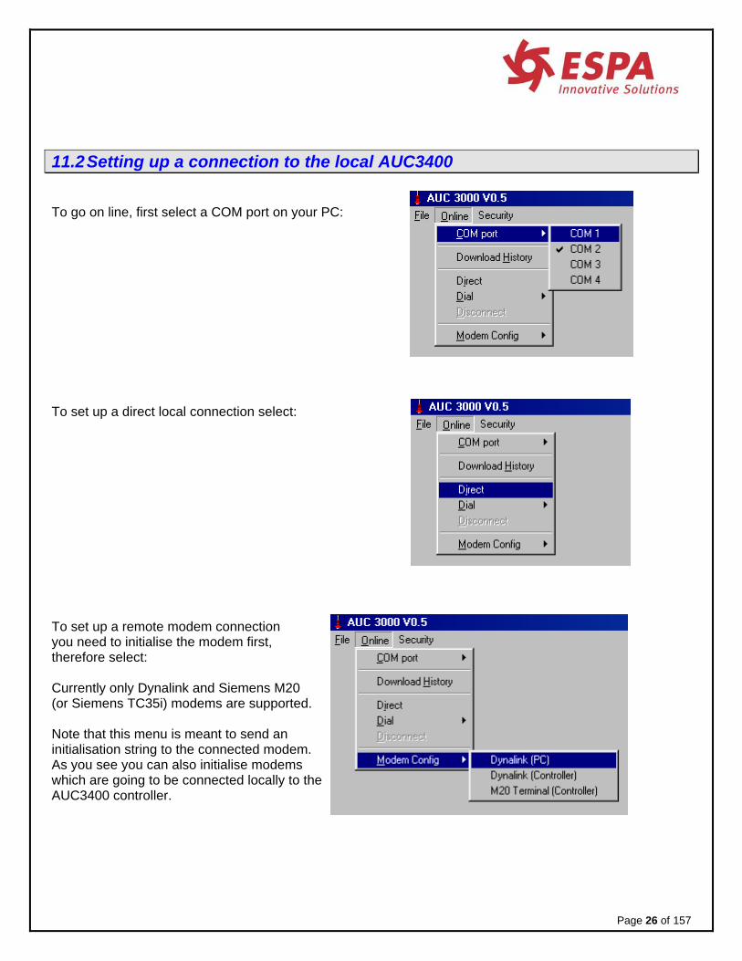
11.2 Setting up a connection to the local AUC3400 To go on line, first select a COM port on your PC: To set up a direct local connection select: To set up a remote modem connection you need to initialise the modem first, therefore select: Currently only Dynalink and Siemens M20 (or Siemens TC35i) modems are supported. Note that this menu is meant to send an initialisation string to the connected modem. As you see you can also initialise modems which are going to be connected locally to the AUC3400 controller.
Page 26 of 157

To set up a remote modem connection dial the number to connect to: If it is a new number select New, otherwise Select it from the list. 11.3 Downloading the alarm history To download the alarm history from the local AUC3400: • on the local HMI or on the virtual HMI on your PC screen, in the alarm history menu (section 15.2.5)
select: • In the AUC3400.exe PC program select:
Page 27 of 157
__DOWNLOAD_HISTORY_ Select the download option in the PC program or ESC...

• A text file will appear on you PC Windows desktop.
The file name is ALARM_YEAR-MONTH-DAY.csv (e.g. ALARM_2004-08-12.csv) The file is ready for importing in MS Excel, just double click the file. Refer to section 15.2.5 for more info. The lay out looks like this: STATUS ALARM Time Date RESET Power failure 11:20:56 07-1-04SET Power failure 11:20:15 07-1-04RESET Pump 4 failure 10:02:49 07-1-04RESET Pump 3 failure 10:02:49 07-1-04RESET Pump 2 failure 10:02:49 07-1-04RESET Pump 1 failure 10:02:49 07-1-04SET Pump 4 failure 10:02:47 07-1-04SET Pump 3 failure 10:02:46 07-1-04SET Pump 2 failure 10:02:46 07-1-04SET Pump 1 failure 10:02:45 07-1-04SET Phase failure 10:02:43 07-1-04RESET Power failure 10:01:42 07-1-04SET Power failure 10:00:38 07-1-04RESET Power failure 10:00:00 07-1-04--End of history--
11.4 Saving the current HMI display to file • Select: • A text file will appear on you PC Windows desktop, it is named SCREEN.TXT.
When you double click the file your default text editor (e.g. NotePad or TextPad) is opened and the HMI display contents appear:
Page 28 of 157

Page 29 of 157

11.5 Documentation When you have commissioned the AUC3400 you may want to have a complete documentation of all readings and settings in the local controller. You can achieve this simply following the next steps: • on the local HMI or on the virtual HMI on your PC screen, in the configuration menu (section15.10.10.4)
select: • In the AUC3400.exe PC program select:
A pop up window appears:
You can choose here if you want borders around the screen which are captured by the PC program from the local HMI for documentation purposes. See the following description for further explanation.
• on the local HMI or on the virtual HMI on your PC screen, select YES.
Page 30 of 157
___DOCUMENTATION___ Have PC program connected. Are you ready? >NO
___DOCUMENTATION___ Have PC program connected. Are you ready? >YES
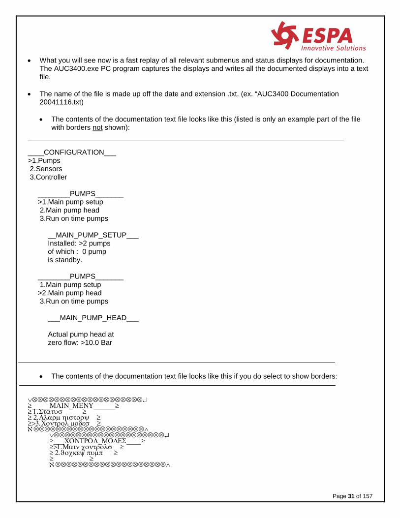
• What you will see now is a fast replay of all relevant submenus and status displays for documentation. The AUC3400.exe PC program captures the displays and writes all the documented displays into a text file.
• The name of the file is made up off the date and extension .txt. (ex. “AUC3400 Documentation
20041116.txt)
• The contents of the documentation text file looks like this (listed is only an example part of the file with borders not shown):
____CONFIGURATION___ >1.Pumps 2.Sensors 3.Controller ________PUMPS_______ >1.Main pump setup 2.Main pump head 3.Run on time pumps __MAIN_PUMP_SETUP___ Installed: >2 pumps of which : 0 pump is standby. ________PUMPS_______ 1.Main pump setup >2.Main pump head 3.Run on time pumps ___MAIN_PUMP_HEAD___ Actual pump head at zero flow: >10.0 Bar
• The contents of the documentation text file looks like this if you do select to show borders:
∨⊗⊗⊗⊗⊗⊗⊗⊗⊗⊗⊗⊗⊗⊗⊗⊗⊗⊗⊗⊗↵ ≥_____ΜΑΙΝ_ΜΕΝΥ______≥ ≥ 1.Στατυσ ≥ ≥ 2.Αλαρμ ηιστορψ ≥ ≥>3.Χοντρολ μοδεσ ≥ ℵ⊗⊗⊗⊗⊗⊗⊗⊗⊗⊗⊗⊗⊗⊗⊗⊗⊗⊗⊗⊗∧ ∨⊗⊗⊗⊗⊗⊗⊗⊗⊗⊗⊗⊗⊗⊗⊗⊗⊗⊗⊗⊗↵ ≥___ΧΟΝΤΡΟΛ_ΜΟΔΕΣ____≥ ≥>1.Μαιν χοντρολσ ≥ ≥ 2.ϑοχκεψ πυμπ ≥ ≥ ≥ ℵ⊗⊗⊗⊗⊗⊗⊗⊗⊗⊗⊗⊗⊗⊗⊗⊗⊗⊗⊗⊗∧
Page 31 of 157

∨⊗⊗⊗⊗⊗⊗⊗⊗⊗⊗⊗⊗⊗⊗⊗⊗⊗⊗⊗⊗↵ ≥ Χοντρολ:>ΟΦΦ ≥ ≥ Π1 Π2 Π3 Π4 ≥ ≥ ΟΦΦ ΟΦΦ ΟΦΦ ΟΦΦ ≥ ≥ 000% 000% 000% 000%≥ ℵ⊗⊗⊗⊗⊗⊗⊗⊗⊗⊗⊗⊗⊗⊗⊗⊗⊗⊗⊗⊗∧ You can open the text file in any text editor, so that you can put your own headers, footers, logos, etc. in the file. Note: you may need to install Windows font MsLineDraw, in order to correctly show the borders. You can use this file as a FAT / SAT document (Factory Acceptance Test / Site Acceptance Test). For that purpose you can also use the MS WORD template document “AUC3400 Documentation template .doc” In this template there is a header page which you can use for FAT/SAT purposes and a comments page. In the template you can insert documentation text file contents. The following pages show some examples of using the template in Ms Word.
Page 32 of 157
Documen-tation page
AUC3400

Front page
Last page
Page 33 of 157
AUC3400
AUC3400

12 AUC3400 display structure The display structure consists of head up displays,
Page 34 of 157 Service code lock
a main menu and a quick setup menu. In the quick setup menu there is a quick commissioning menu.
In case of alarm callmpController I
18:39 01:07:2004
5.:
___SETPOINT_STATUS__Active = 5.0 Bar Setpoint = 5.0 Bar Source = Local
____PUMP_SEQUENCE___ P1 P2 P3 P4 1 2 3 4
Setpoint: 5.0 BarPressure: 5.0 Bar Speed : 189.4 %
P1 : 0.9 hrs P2 : 1.1 hrs P3 : 0.7 hrs P4 : 0.2 hrs
P1 P2 P3 P4 AUTO AUTO AUTO AUTO RUNS RUNS STBY STBY 100% 89% 0% 0%
No password required
____QUICK_SETUP_____>Pump setup Control speed
Frequency converters Suction switch Quick commissioning Pump simulator Control modes Set clock Erase alarm history
Quick Setup
Head up Displays
________KWH_________ Total: 0.0 kWhPeriod: 0.0 kWh
_____JOCKEYPUMP_____ Mode AUTO Status STBY
__START_CONDITIONS__ Everything seems OK. ______PRESURE_______
Discharge: 5.0 BarInlet : 0.5 Bar Rate : 17.5 m3/h
Home
UP
Home
User password required
DownMain Menu _____MAIN_MENU______ >Status Alarm history Event history Control modes Pump sequence Pump / tank test Setpoints Zero flow detection Clock Configuration Password
________FLOW________Rate : 39.5 m3/h Total: 47.2 m3Period: 47.2 m3
LEFT
Service password required
RIGHT
Service
Password required

13 AUC3400 Head up displays Head up displays appear when the AUC3400 is powered up or when you press the home key. They list all relevant status information. The head up displays are accessible by everyone, no password is required. Use the arrow keys LEFT and RIGHT to manoeuvre through the displays.
0 As each of these displays can be found in the menu, they will be discussed in further detail later in this manual.
Page 35 of 157 Adjustable Optional menu Service code lock
J1 J2 P3 P4 AUTO AUTO AUTO AUTO RUNS RUNS STBY STBY 0% 0% 100% 100%
In case of alarm Call: 000000 000000 (5.0) MEFJ6–V3.1 SIM 5.01 175% RRSSSSFF
Setpoint: 5.00 Bar Pressure: 4.99 Bar Speed : 189.4 % Min speed: 68.6 %
J1-P1 Hz-Amp-kW50.0 50.0 43.7 0.0 3.4 3.4 2.9 0.0 1.7 1.7 1.4 0.0
____PUMP_SEQUENCE___ Pump 1 2 3 4 5 6 7 8Seq. 4 5 6 7 8 1 2 3
P1 : 10110.9 hrsP2 : 09097.1 hrs P3 : 500.7 hrs P4 : 490.2 hrs
__START_CONDITIONS__* No AUTO mode * No pump available * Setpoint<pressure
P5-P8 Hz-Amp-kW50.0 50.0 43.7 0.0 3.5 3.4 2.9 0.0 1.7 1.7 1.4 0.0
___SETPOINT_STATUS__Active = 5.0 Bar Setpoint = 5.0 Bar Source = Local
__PRESSURE_/_FLOW___ Discharge: 5.0 Bar Suction : 0.5 Bar Rate: 35.5 m3/h
_PRE_PRESSURE_PUMPS_ P1 P2 Mode AUTO AUTO Status RUN RUN
________FLOW________Rate : 39.5 m3/h Total: 47.2 m3Period: 47.2 m3
_CAVITATION_STATUS__Cav.point: 80.0 m3/h Q at 100%: 75.0 m3/h Pumps in parallel: 2
P5 : 489.9 hrs P6 : 521.1 hrs P7 : 534.7 hrs P8 : 540.6 hrs
P5 P6 P7 P8 AUTO AUTO AUTO AUTO RUNS RUNS STBY STBY 100% 89% 0% 0%
___VIRTUAL_FLOW_____J1 = 20.5 J2 = 20.6
P3 = 18.2 P4 = 0.0Total: 47.2 m3/h
________KWH_________ Total: 0.0 kWhPeriod: 0.0 kWh
___VIRTUAL_FLOW_____P5 = 20.5 P6 = 20.6
P7 = 18.2 P8 = 0.0Total: 47.2 m3/h
_PRE_PRESSURE_PUMPS_ P1 P2 P3 P4 AUTO AUTO AUTO AUTO
NS RUNS STBY STBY RU
_____JOCKEYPUMP_____ Mode AUTO Status STBY

Notes: the head up display you selected most recently will be the one reappearing after you pressed Home. Furthermore, if you don’t touch any keys for 5 minutes the most recent head up display will also reappear automatically. Only relevant information is displayed. For example, if you have only two main pumps installed no information about other pumps will appear. 13.1 The default head up display One display, the standard or default head up display, can only be found here and not in the status menu: The two top lines can be edited (refer to section 15.10.10.3). Any user defined text can be displayed here. MEF identifies the AUC3400 control software (freq. control)
(J)ockey (6) main pumps. V2.5 stands for software version 1.0. SIM (blinking) indicates: pump set simulator active.
In case of alarm Call: 000000 000000 (5.0) MEFJ6–V2.5 SIM 5.1 175% RFSHOSS
Indicates the status of all pumps: • R = Running (in this case the Jockey pump) • F = Failure (in this case main pump 1) • S = Standby (in this case main pump 2) • H = Hand on (in this case main pump 3) • O = OFF (in this case main pump 4)
Notes: - The text MEFX can be replaced by the actual flow rate (refer to section 15.10.3.4.5) how to select this
option. - If a remote stop is activated the text “REMOTE STOP” will blink and overlay the text MEFX. As mentioned by the top display line you can alter the contents. In the configuration menu you will find a sub menu called Head up display where you can edit the contents of the top two lines. The default text is shown here. You may want to edit the telephone number, but you just as well put in any other desired text. Refer to section 15.10.10.3 for more details. When you have commissioned the AUC3400 and specified what text you would like to see in the top two lines of the default head up display, you may want to lock the default head up display. There are two options:
1. You select the default head up display to be the only visible head display. That means that no operator can select any other head up display. However the menu is still accessible.
2. You can lock the menu as well. Now no operator can selected any other head up display and not access the menu system either. The default head display (with your specified text) will remain the only visible display. To access the menu system, the operator will have to specify the service access code. For more information refer to section 15.10.10.1 in the configuration menu.
Total speed
(0-400%)
Pressure and
(setpoint)
PC (alternating with the setpoint) means a PC has a direct or
remote connection (through a modem)
Page 36 of 157 Adjustable Optional menu Service code lock

Page 37 of 157 Adjustable Optional menu Service code lock
14 AUC3400 Quick Setup The quick setup menu lists the most commonly used items and is intended for usage in the workshop of the supplier and for commissioning in the field. For commissioning purposes a menu option <Quick commission> is available in the quick setup menu. The quick setup can only be access by service personnel. From the head up displays, press arrow UP to access the Quick setup menu. Use the UP and DOWN arrow keys to scroll up or down and press enter or RIGHT arrow to select an option. Note: the menu options listed here are described in detail in the section numbers as indicated behind each option. 15 AUC3400 menu The menu is a hierarchical structure of related items, containing sub menus, status information and settings used for setting up, controlling and monitoring the pump application. IMPORTANT The menu is a dynamic system. The options that are described in the manual are all present in each AUC3400 but may not appear in your menu system because there are hidden.
____QUICK_SETUP______(section)>Pump setup (15.10.1.2) Control speed (113) Frequency converter (15.10.2) Suction switch (15.10.3.2.6) Quick commission (14)
8) Pump simulator (15.10.4. Control modes (15.4.1) Set clock (15.9.2)
__QUICK_COMMISSION__(section)>Pump application (84) Main pump curve (15.10.1.3) DOL jockey pump (93) Run on time pumps (15.10.1.9) Sensors (15.10.3) Quick setpoint (15.7.2) Setpoint menu (15.7) Pump / tank test (15.6.4) Pump change hours (15.5.1.2) Pressure tank test (15.6.3) Service setting (15.10.11)
Service
Service

Options are hidden when they are not relevant in your configuration. Your configuration is set up in the Quick setup and Quick commissioning menu. Examples:
• if your configuration is set up to control 2 main pumps, you will find no information about the other possible 6 pumps that can be controlled.
• If a user logs in without the service code, only view options can be seen in the main menu. • The first option in the Quick commissioning menu prompts for the pump application. You may
choose between pressure boosting and irrigation. If you choose the latter you find additional options such as pre-pressure pumps suddenly available in the menu.
From the head up displays, press arrow DOWN or ENTER to access the Main menu.
_____MAIN_MENU______ >Status
Alarm history Event history Control modes Pump sequence Pump / tank test Setpoints
n Zero flow detectio Clock Configuration Password
Use the UP and DOWN arrow keys to scroll up or down and press enter or RIGHT arrow to select an option. The current option being considered below is indicated by the “>” sign. 15.1 Status
MAIN menu >
_______STATUS_______ >Start conditions Pumps and drives Main pump sequence
e Pre-press. sequenc Pressure Flow Setpoint Power consumption
The status sub menu contains status information concerning the system. Most of this information can also be found in the head up displays.
Page 38 of 157 Adjustable Optional menu Service code lock

15.1.1 Start conditions MAIN menu > Status >
__START_CONDITIONS__ * failure: shut down * no AUTO mode * no pump available
If the system won’t run, you may consult the start conditions. It will show you why pumps are not in operation. The following hints may appear: • Everything is OK (System should be up and running) • Failure: shut down (There is a shut down failure, press the alarm key to see what it is) • No AUTO mode (Go to Control modes and select AUTO mode) • No pump available (All pumps have failed or their control mode is OFF) • Remote stopped (Control was remotely stopped by a digital contact) • No setpoint (0) (No setpoint was specified or zero, go to the setpoints menu) • Setpoint < pressure (The actual setpoint is less than the actual pressure)
15.1.2 Pumps and drives
MAIN menu > Status >
___PUMP_AND_DRIVES__ >Main pumps (1-4) Main pumps (5-8) Prepress. pumps Jockey pump (DOL) Hz, Amp’s & kW Running hours FC drive status
Note: depending on your configuration you may see other descriptions here. For example if you have only two main pumps and nothing else this menu will appear as:
___PUMP_AND_DRIVES__ >Main pumps Hz, Amp’s & kW Running hours FC drive status
Page 39 of 157 Adjustable Optional menu Service code lock

Page 40 of 157 Adjustable Optional menu Service code lock
15.1.2.1 Main pumps
MAIN menu > Status > Pump and drives Line 1 shows the available pumps. Line 2 shows the pump modes (AUTO – OFF – HAND) Line 3 shows the status (RUNS – STANDBY – OFF – ERROR – H-ON ‘= Hand on’) Line 4 shows the speed of the pump (0 – 100 %) Note: if you have configured the AUC3400 to control a different number of pumps, then the pump status display will look different as well. For example: if you have 2 pumps installed you would get the following display lay out: Note: if you have external selector switches on the door of the panel, AUTO - HAND and OFF modes will indicates the position of those switches. If you do not have external switches, then AUTO - HAND and OFF will follow the selections made in the control mode menu. The AUC3400 obtains the presence and status of external mode selector switches through the frequency converter and the communications bus. 15.1.2.2 Pre-pressure pumps
MAIN menu > Status > Pump and drives >
Line 2 shows the available pre-pressure pumps. Line 3 shows the pump modes (AUTO – OFF – HAND) Line 4 shows the status (RUNS – STANDBY – OFF – ERROR – H-ON ‘= Hand on’)
Note: if you have configured the AUC3400 to control a different number of pumps, then the pump status display will look different as well. Note: if you have external selector switches on the door of the panel, AUTO - HAND and OFF modes will indicates the position of those switches. If you do not have external switches, then AUTO - HAND and OFF will follow the selections made in the control mode menu.
P1 P2 P3 P4 AUTO AUTO AUTO AUTO RUNS RUNS STBY STBY 100% 89% 0% 0%
P1 P2 Mode AUTO AUTO Status RUNS RUNS Speed 100% 89%
_PRE_PRESSURE_PUMPS_ P1 P2 Mode AUTO AUTO Status RUNS RUNS

Page 41 of 157 Adjustable Optional menu Service code lock
15.1.2.3 Jockey pump
MAIN menu > Status > Pump and drives
Line 2 shows the pump modes (AUTO – OFF – HAND) Line 3 shows the status (RUNS – STANDBY – OFF – ERROR) Note: refer to section 15.7.11 for a description about jockey pump control.
15.1.2.4 Hz, Amp’s and kW’s
MAIN menu > Status > Pump and drives This readout window shows the measured values of each pump as received over the serial bus line from the frequency converters. 2nd line shows the frequency of each pump 3rd line show the amp readings of each pump
4th line shows the kilowatts of each pump 15.1.2.5 Running hours
MAIN menu > Status > Pump and drives > The controller continuously updates total hours and periodical hours. The total hours counter always continues and cannot be reset. Periodical hours can be reset as often as necessary.
_____JOCKEYPUMP_____ Mode AUTO Status STBY
P1-P4 Hz-Amp-kW 50.0 30.0 0.0 0.0 1.8 1.0 0.0 0.0 0.7 0.3 0.0 0.0
___RUNNING_HOURS____ >Main total Main periodical Pre-press total Pre-press period Jockey pump (DOL) Reset periods

15.1.2.5.1.1 Main total hours
MAIN menu > Status > Pump and drives > Running hours >
P1 : 100.2 hrs P2 : 90.1 hrs P3 : 88.9 hrs P4 : 103.4 hrs
15.1.2.5.2 Main periodical hours
MAIN menu > Status > Pump and drives > Running hours >
P1 : 1.3 hrs P2 : 1.6 hrs P3 : 0.7 hrs P4 : 0.2 hrs
15.1.2.5.3 Pre-press total hours
MAIN menu > Status > Pump and drives > Running hours >
P1 : 100.2 hrs P2 : 90.1 hrs P3 : 88.9 hrs P4 : 103.4 hrs
15.1.2.5.4 Pre-press periodical hours
MAIN menu > Status > Pump and drives > Running hours >
P1 : 1.3 hrs P2 : 1.6 hrs P3 : 0.7 hrs P4 : 0.2 hrs
Page 42 of 157 Adjustable Optional menu Service code lock

Page 43 of 157 Adjustable Optional menu Service code lock
15.1.2.5.5 Jockey pump (DOL)
MAIN menu > Status > Pump and drives > Running hours >
15.1.2.5.6 Reset period
MAIN menu > Status > Pump and drives > Running hours > As soon as this option is selected, the periodical hours are reset. 15.1.2.6 FC drives status
MAIN menu > Status > Pump and drives > The AUC3400 controller receives the status of each frequency converter (FC drive) over the bus line. That status is displayed for each pump, for example the first pump will display something similar to the following information:
The periodical Run hours are reset.
___FC_DRIVE_STATUS__ >FC drive pump 1 FC drive pump 2 FC drive pump 3 FC drive pump 4 FC drive pump 5 FC drive pump 6 FC drive pump 7 FC drive pump 8
COM1 OK: 2334 ER: 5 RUNS: SPEED = REF CRDY DRDY STBY TRIP WARN VH/L ILIM TH-W
Service
__JOCKEY_PUMP_(DOL)_ Running hours. Total: 0.0 Period: 0.0

Indication Meaning COM1 communication with FC drive 1 for pump motor 1 2334 / 5 communication protocols were OK, but 5 had an error. Those numbers
indicate whether the communication is working good or not. Normally an error rate of 1 to 5 per thousand is normal.
RUNS the pump motor is running SPEED = REF that the motor runs at exactly the speed requested by the AUC3400.
SPEED <> REF means that the motor is ramping up or down to the requested speed. You may see this appears very briefly as the speed is adjusted.
CRDY Control Ready, the drive is healthy and ready for operation DRDY Drive ready, waiting for a start signal TRIP Drive has an error or failure and needs to be reset. Read the FC display to see
what error caused the drive to trip. In case of a Danfoss VLT 2800 you need to look up the error number being displayed in the Danfoss manual. In case of a Danfoss VLT 6000 the cause of the error is displayed in plain text. In case of a Danfoss FC200, look below or at the FC200 display for an alarm message or at FC200 menus 1690 and 1691 for detailed alarms.
WARN There is a warning situation. Like a trip you can read at the FC display what caused the warning.
VH/L Voltage high / low (DC link voltage, FC200 only) See also section @@@. ILIM Current limit. (FC200 only) See also section @@@.) TH-W Thermistor failure warning (FC200 only). See also section @@@. 15.1.3 Main pump sequence
MAIN menu > Status > The status display show one of two versions, depending on if the hourly pump change was enabled (section15.5). If it is enabled you will see: or
____PUMP_SEQUENCE_______PUMP_SEQUENCE___ Change: 42 min. Change: 39.51 hrs P1 P2 P3 P4 P1 P2 P3 P4 2 3 4 1 2 3 4 1
If the hourly pump change was disabled: Start
____PUMP_SEQUENCE___ P1 P2 P3 P4 2 3 4 1
Page 44 of 157 Adjustable Optional menu Service code lock

Page 45 of 157 Adjustable Optional menu Service code lock
Note: if you have a pump configuration with frequency controlled jockey pumps the jockeys are indicated by a capital J. They also have their own pump sequence, prior to the main pumps. For example, suppose the pump sequence with 2 with frequency controlled jockey pumps is: Then after a pump change the sequence will become: 15.1.4 Pre-pressure pump sequence
MAIN menu > Status > The status display show one of two versions, depending on if the hourly pump change was enabled (section 15.1.3). If it is enabled you will see: or If the hourly pump change was disabled: Start
____PUMP_SEQUENCE___ J1 J2 P3 P4 1 2 3 4
____PUMP_SEQUENCE___ J1 J2 P3 P4 2 1 4 3
____PUMP_SEQUENCE___ Change: 39.51 hrs
P1 P2 P3 P4 2 3 4 1
____PUMP_SEQUENCE___ P1 P2 P3 P4 2 3 4 1
____PUMP_SEQUENCE___Change: 42 min. P1 P2 P3 P4 2 3 4 1

Page 46 of 157 Adjustable Optional menu Service code lock
15.1.5 Pressure MAIN menu > Status >
Discharge pressure, suction pressure and flow are updated and displayed. If no suction pressure sensor is installed, the fixed suction pressure specified in the configuration menu is shown (refer to section 15.10.3.2.1). The flow rate can be a value derived either from an analogue input from flow meter, a pulsed digital input from a totalising flow meter, or a calculated virtual flow value. Refer to section 15.10.3.4 for details on how to configure the flow measurements. 15.1.6 Flow
MAIN menu > Status > The controller continuously updates the flow rate (m3/h), the total pumped volume (m3) and the periodically pumped volume (m3). The total counter always continues and cannot be reset. The periodic counter can be reset as often as required. 15.1.6.1 Flow readings
MAIN menu > Status > Flow > The flow rate can be a value derived from either an analogue input from flow meter, a pulsed digital input from a totalising flow meter, or a calculated virtual flow value. Refer to section 15.10.3.4 for details on how to configure the flow measurements.
___PRESURE_/_FLOW___ Discharge: 5.00 Bar Suction : 0.48 Bar Rate: 17.3 m3/h
________FLOW________ >Readings Reset period Virtual flow
________FLOW________ Rate : 39.5 m3/h Total: 65.8 m3 Period: 65.8 m3

Page 47 of 157 Adjustable Optional menu Service code lock
15.1.6.2 Reset period
MAIN menu > Status > Flow > As soon as this option is selected, the periodical flow counter is reset. 15.1.7 Virtual flow
MAIN menu > Status > Flow > Shows the virtual flow calculated by the AUC3400 based on the pressure and the pump curve of the pump. Refer to section 15.10.3.4.3 for more information. Note: if virtual flow is not enabled, you will not find this option in the menu. 15.1.8 Setpoint
MAIN menu > Status > Actual Shows what the current value for the selected setpoint is.
It may differ from the “Setpoint”, because of the programmed setpoint ramp. This ramp slows down the changes in setpoint levels. Refer to the setpoint ramp in the setpoint menu section 15.7.9.
Setpoint Shows the currently selected setpoint. Source Indicates Local or Remote setpoint.
A local setpoint is obtained from the week program. A remote setpoint can be externally activated by a digital input. The reference for an external setpoint is an analogue input signal coming from an external source.
___VIRTUAL_FLOW_____ P1 = 20.5 P2 = 20.6 P3 = 18.2 P4 = 0.0 Total: 47.2 m3/h
The periodical counter is reset.
___SETPOINT_STATUS__ Actual = 5.0 Bar Setpoint = 5.0 Bar Source = Local
Service

Page 48 of 157 Adjustable Optional menu Service code lock
Note: if you have not enabled the external setpoint, source will not be relevant and thus not appear.
15.1.9 Power consumption
MAIN menu > Status > The power consumption is calculated from a digital input. For configuration of the kWh refer to section 15.10.3.5 The controller updates a total kWh and a periodical kWh counter. The total counter always continues and cannot be reset. The periodical counter can be reset as often as required. 15.1.9.1 Readings
MAIN menu > Status > Power consumption > 15.1.9.2 Reset period
MAIN menu > Status > Power consumption > As soon as this option is selected the periodical kWh counter is reset.
_________kWh________ >Readings Reset period
________KWH_________ Total: 145.6 kWh Period: 8.9 kWh
The periodical counter is reset.
Service

15.2 Alarms MAIN menu > alarm history >
Alarms in the AUC3400 are handled by the following procedures:
1. The alarm led on the fronts starts blinking each time a new alarm is triggered. 2. The general alarm contact on the terminals breaks (fail save, potential free, relay contact). 3. The alarm possible causes the AUC3400 to stop one or more pumps.
(depending on the nature and consequences of the concerned alarm) 4. The alarm will show up in the alarm list (press the alarm button) 5. The alarm is recorded in the alarm history (to be found in the menu). 6. The alarm is possible send by SMS to a registered recipient. 7. If the AUC3400 PC program is on line, the alarm will be shown on the PC. 8. If a modem SMS pool is configured the alarm may be relayed to several recipients. 9. If the PC program is connected you can download the alarm history to the PC and store the alarms
in a .csv file (comma separated file) which may be imported to MS Excell.
This section continues describing the alarm history menu. The menu present a history of alarms and the opportunity to generate alarm SMS messages and download the history to a PC. The above options will be discussed later; first a description is given for the actual alarms. 15.2.1 Actual alarms
Direct access by alarm button The actual alarms can be accessed by means of the red alarm button. If you view the actual alarms list you will get the following display when no alarm is active: If there is an alarm you get something similar to this example:
______ALARMS_______ >History Erase history Download to PC Enable alarm SMS
No alarm active.
* Phase failure * Pump 1 failure Enter = reset
Page 49 of 157 Adjustable Optional menu Service code lock

In this case there is a pump failure and a phase failure. Note: each time a new failure appears, the red alarm L.E.D. starts blinking. Press the enter key to reset failures. If a failure cannot be reset, because the fault condition has not been cleared, the alarm L.E.D. stops blinking and is continuously illuminated. This indicates you have seen the alarm and acknowledged it. If the fault condition has been cleared, press the reset again and the alarms will disappear from the display and the alarm L.E.D. will go off. Remember that resetting alarms will also restart your pumps, if no further alarms are present. Notes: • pump alarms will automatically reset, you do not need to specifically reset manually on the AUC3400.
Inlet alarms and high discharge alarms will automatically reset after a specified time (refer to sections 15.10.3.2.4 and 15.10.3.1.3)
Page 50 of 157 Adjustable Optional menu Service code lock

15.2.2 Alarm overview Nr Alarm Description 1 Pump 1 failure 2 Pump 2 failure 3 Pump 3 failure 4 Pump 4 failure 5 Pump 5 failure 6 Pump 6 failure 7 Pump 7 failure 8 Pump 8 failure
Pump failure. A pump failure is caused by:
• a tripped circuit breaker (check motor rating) • a tripped frequency converter (section 15.1.2.6) • a communication failure (see next error)
9 Drive 1 COM error 10 Drive 2 COM error 11 Drive 3 COM error 12 Drive 4 COM error 13 Drive 5 COM error 14 Drive 6 COM error 15 Drive 7 COM error 16 Drive 8 COM error
FC drive communications error. The AUC3400 controls the frequency converters over the RS485 serial bus. The communication is no longer possible when this error appears. Check the cable connection and if the frequency converter is online (power on and no errors in the display of the drive).
17 Failure flow meter Broken sensor cable of the flow meter, check cable. 18 Phase failure (SD) One or more of the incoming power phases failed. 19 Inlet wire break (SD) Broken sensor cable of the inlet sensor, check cable. 20 R.setp.wire break Broken sensor cable of the remote setpoint, check cable. 21 Disch.wire break (SD) Broken sensor cable of the discharge sensor, check cable. 22 Dry running (SD) Inlet pressure is too low (section 15.10.3.2.3 / 15.10.3.2.6). 23 High disch.press. Discharge pressure is too high (section 15.10.3.1.2 / 15.10.3.1.7). 24 Low disch.press. (SD) Discharge pressure is too low (section15.10.3.2.3). 25 Power failure (SD) Incoming power on the main failed. 26 Jockey pump fail. The direct on line operated jockey circuit breaker tripped. 27 Service due Service visit is to be scheduled (see section 15.10.11). 28 Flow > threshold Flow was higher than the set threshold (see section 15.10.3.4.6). 29 Pres.tank air low Low air pressure in the diaphragm tank (section 15.6.3). 30 Pres.tank air high High air pressure in the diaphragm tank (section 15.6.3). 31 COM err. IO mod.1 32 COM err. IO mod.2 33 COM err. IO mod.3 34 COM err. IO mod.4
The pre-pressure pumps are controlled by remote I/O modules. The AUC3400 communicates with the remote I/O modules over the RS485 bus. The connection was lost. Check the communication cable and the power on the remote modules.
35 Write er.remoteIO A command of the AUC3400 was not accepted. 36 Preprespump1fail. (*SD) 37 Preprespump2fail. (*SD) 38 Preprespump3fail. (*SD) 39 Preprespump4fail. (*SD) 40 Preprespump5fail. (*SD) 41 Preprespump6fail. (*SD) 42 Preprespump7fail. (*SD) 43 Preprespump8fail. (*SD)
Pre-pressure pump failure. A pre-pressure pump failure is caused by:
• a tripped circuit breaker (check motor rating) • a tripped converter (section 15.1.2.6) • a communication failure (see previous errors)
44
Leakage detected. (SD) Pump(s) started more often than allowed (section 15.6.4)
Page 51 of 157 Adjustable Optional menu Service code lock
Nr Alarm Description

45 P1 thermistor hot 46 P2 thermistor hot 47 P3 thermistor hot 48 P4 thermistor hot 49 P5 thermistor hot 50 P6 thermistor hot 51 P7 thermistor hot 52 P8 thermistor hot
Pump thermistor error Note: this alarm applies only to Danfoss FC200 drives. Thermistors are thermally sensitive resistors and have a positive (PTC) resistance/temperature coefficient. Build into the pump motor they signal high, possibly dangerous motor temperatures. The thermistor is connected to the frequency converter drive. The AUC3400 read the error and stops the concerned pumps to protect from damage. Thermistors must selected in the menu (See section @@@@).
53 P1 currentlimited 54 P2 currentlimited 55 P3 currentlimited 56 P4 currentlimited 57 P5 currentlimited 58 P6 currentlimited 59 P7 currentlimited 60 P8 currentlimited
Note: this alarm applies only to Danfoss FC200 drives. The frequency converter drive may limit the current drawn by a pump when overloaded due to heavy load. If you want to detect this, you can enable menu option in the frequency converter menu.
61 P1 DC link V-H/L 61 P2 DC link V-H/L 62 P3 DC link V-H/L 63 P4 DC link V-H/L 64 P5 DC link V-H/L 65 P6 DC link V-H/L 66 P7 DC link V-H/L 67 P8 DC link V-H/L
The frequency converter drive may suffer a low DC link voltage when problems with the supply voltage occur. If you want to detect this, you can enable menu option in the frequency converter menu
68 High water level High water detected. This alarm comes from an optional external level controller. It signals a high water level in the well or possibly in the control room.
69 Forced (FC) stop (SD) You can select to connect an optional contact to the AUC3400 inputs, indication an emergency stop. (section 15.10.8). If selected the AUC3400 will raise an alarm and stop the pumps using DC braking. Normally the pumps will have a coasted stop. Note: the AUC3400 must reprogram the drives for this option.
Notes: (SD) indicates Shut Down alarm. All the pumps are stopped when such alarm is raised.
Page 52 of 157 Adjustable Optional menu Service code lock
(*SD) indicates a possible shut down caused by pre-pressure pumps. If depends on the number of available pre-pressure pumps if the system is completely shut down.

15.2.3 History
MAIN menu > Alarm history > In the history you will find on each display: • The alarm description • Coming (*) or going (-) of fault • Time of coming (*) or going (-) of fault • Date of coming (*) or going (-) of fault • The alarm index, for example 1/50 means alarm record 1 out of 50 alarms in total. Examples: - Phase failure This alarm is going “-“. In this case it means the alarm was reset by the operator at the stated
time and date. Time: 12:38:36 Date: 01-07-04 1/50
Note: That power failure appears only in the alarm history and not in the actual alarm list. This is because the alarm cannot be viewed during the power failure and is automatically reset when the power is restored. However, the alarm L.E.D. will be illuminated.
Note: The history records a maximum of 99 alarms. After that, the oldest alarm is removed from the history to allow the entry of a new alarm. 15.2.4 Erase history
MAIN menu > Alarm history > After selecting this option the alarm history is reset (service password required).
* Power failure Time: 10:00:00 Date: 01-07-04 50/50
* Pump 1 failure Time: 10:02:45 Date: 01-07-04 45/50
Service
The alarm history is erased.
Page 53 of 157 Adjustable Optional menu Service code lock

15.2.5 Download history PC Service
MAIN menu > Alarm history >
__DOWNLOAD_HISTORY_ Select the download option in the PC program or ESC...
With the AUC3400.exe PC program you can operate the controller from a remote site, for example your office. In the AUC3400 PC program is a download option. You can use this to download the complete alarm history to a PC. Refer to chapter 11.3 for further information. 15.2.6 Enable alarm SMS Service
MAIN menu > Alarm history > I you want you can order an optional Siemens C35i modem and receive SMS alarm messages on your mobile phone. Refer to section 15.10.5 for selecting the type of modem you use. Before you can have the modem operating, you need to order a data SIM card from your local provider and insert this into the modem slot. The Siemens modem has no digital input. SMS messages are controlled and sent by the AUC3400 through command string over the serial connection between AUC and TC35i. SMS messages are sent when you set the following option to YES:
_____ALARM_SMS______ 0 alarms waiting Next SMS in: 0 sec. Enable SMS: >NO
On the second line the AUC3400 indicates the number of alarms waiting to be send by SMS. However, if you disable SMS (by selecting NO) the send buffer will remain empty and no alarms will be transmitted. Therefore, when you do a commissioning or servicing you can disable the transmittal of SMS messages. When you are done commissioning or servicing, enable the SMS messages again. If you have enabled SMS and failures occur, they are placed in an internal transmission buffer of the AUC3400. The alarms in the buffer will be send one at the time with an interval of 20 seconds. This delay is necessary for the modem, because it needs time for each SMS transmittal. The time delay is visible on the third line. When you power up the panel there will be a one minute delay before the first possible SMS will be transmitted. This delay is required for the start up sequence of the modem (connecting to the GSM network and provider).
Page 54 of 157 Adjustable Optional menu Service code lock

Page 55 of 157 Adjustable Optional menu Service code lock

15.3 Events MAIN menu > event history >
This event menu presents a history of events and a way to download the history to a PC. The above options will be discussed later; first all available events are listed:
Pump 1 started Main pump 1 was started Pump 2 started Main pump 2 was started Pump 3 started Main pump 3 was started Pump 4 started Main pump 4 was started Pump 5 started Main pump 5 was started Pump 6 started Main pump 6 was started Pump 7 started Main pump 7 was started Pump 8 started Main pump 8 was started Pump 1 stopped Main pump 1 was stopped Pump 2 stopped Main pump 2 was stopped Pump 3 stopped Main pump 3 was stopped Pump 4 stopped Main pump 4 was stopped Pump 5 stopped Main pump 5 was stopped Pump 6 stopped Main pump 6 was stopped Pump 7 stopped Main pump 7 was stopped Pump 8 stopped Main pump 8 was stopped PrePump 1 started Pre-pressure pumps 1 was started PrePump 2 started Pre-pressure pumps 2 was started PrePump 3 started Pre-pressure pumps 3 was started PrePump 4 started Pre-pressure pumps 4 was started PrePump 5 started Pre-pressure pumps 5 was started PrePump 6 started Pre-pressure pumps 6 was started PrePump 7 started Pre-pressure pumps 7 was started PrePump 8 started Pre-pressure pumps 8 was started PrePump 1 stopped Pre-pressure pumps 1 was stopped PrePump 2 stopped Pre-pressure pumps 2 was stopped PrePump 3 stopped Pre-pressure pumps 3 was stopped PrePump 4 stopped Pre-pressure pumps 4 was stopped PrePump 5 stopped Pre-pressure pumps 5 was stopped PrePump 6 stopped Pre-pressure pumps 6 was stopped PrePump 7 stopped Pre-pressure pumps 7 was stopped PrePump 8 stopped Pre-pressure pumps 8 was stopped
______EVENTS_______ >History Erase history Download to PC
Page 56 of 157 Adjustable Optional menu Service code lock

Jockey started Jockey pump was started Jockey stopped Jockey pump was stopped User logged in Operator with user level logged in User logged out Operator with user level logged out Server logged in Operator with service level logged in Server logged out Operator with service level logged out Fire mode started Fire mode was started Fire mode stopped Fire mode was stopped Pump blocking on Pump blocking mode was started Pump blocking off Pump blocking mode was stopped Remote start AUC3400 received remote start (over digital inputs) Remote stop AUC3400 received remote stop (over digital inputs)
15.3.1 Event History
MAIN menu > Alarm history > In the history you will find on each display: • The event description • Time of event • Date of event • The event index, for example 1/50 means event record 1 out of 50 events in total. Examples: Server logged in In this case it means that a service man logged into the AUC3400. Time: 12:38:36 Date: 01-07-04 1/50
Pump 4 started Pump 4 started Time: 10:00:00
Date: 01-07-04 50/50 .
Note: The history records a maximum of 99 events. After that, the oldest event is removed from the history to allow the entry of a new event (FIFO principle, first in first out).
Page 57 of 157 Adjustable Optional menu Service code lock

15.3.2 Erase history Service
MAIN menu > Event history > After selecting this option the alarm history is reset (service password required).
The Event history is erased.
15.3.3 Download history PC Service
MAIN menu > Alarm history >
__DOWNLOAD_HISTORY_ Select the download option in the PC program or ESC...
With the AUC3400.exe PC program you can operate the controller from a remote site, for example your office. In the AUC3400 PC program is a download option. You can use this to download the complete event history to a PC. Refer to chapter 11.3 for further information. 15.4 Control modes Service
MAIN menu > In the control modes section, the pumps can be selected for automatic operation (AUTO mode), manual control operation (HAND mode) or disabled operation (OFF mode). Note: if your setup does not included pre-pressure pumps nor jockey pumps you will be forwarded directly to the following menu:
___CONTROL_MODES____ >Main pumps Pre-pressure pumps Jockey pump (DOL)
Page 58 of 157 Adjustable Optional menu Service code lock

Page 59 of 157 Adjustable Optional menu Service code lock
15.4.1 Main pumps
MAIN menu > Control modes >
e selected (AUTO – OFF – HAND - ALL)
OFF – HAND) ine 4 shows the speed of the pump (0 – 100 %)
l re adjustable:
you do not have external selector switches
Line 1 shows the overall system modLine 2 shows the available pumps. Line 3 shows the individual pump modes (AUTO –L A l the following fields a If for each pump, the following rules apply:
All pumps are automatically switched to OFF mode. You cannot put any pump in AUTO or HAND.
HAND then all pumps automatically switch
nd type in a value, press enter again. The pump will
again in HAND mode, running at the speed where you left then before the shut down failure occurred.
mode was HAND before you selected control mode AUTO then all pumps in HAND remains in
Control mode = OFF: • Control mode = HAND: • If control mode was AUTO before you selected control mode
over to OFF mode, except for the pumps already running in HAND (In AUTO mode you can still select a pump in manual = HAND)
• You can put a pump in HAND or OFF mode, but not in AUTO mode. • After you have selected HAND mode for a pump you can control the speed of that pump. Move the
cursor “>” to the required speed field, press enter aimmediately start operating at the selected speed.
• Important note: In HAND mode, alarms like low / high pressure will stop the pump, just like in AUTO mode. After a shut down failure is reset the pumps automatically start
Control mode = AUTO: • If control
HAND.
Control: AUTO P1 P2 P3 P4 AUTO AUTO AUTO AUTO 100% 089% 000% 000%
Control:>AUTO P1 P2 P3 P4 AUTO AUTO AUTO AUTO 100% 089% 000% 000%

Page 60 of 157 Adjustable Optional menu Service code lock
• You can put a pump in AUTO, OFF mode and in HAND mode (so you can have pumps in mixed modes).
In AUTO mode all applicable protections apply (shut down in case of certain failures)
Puts the control mode in AUTO and also puts all the pumps in AUTO. After you selected this, the display ckey pumps.
elector switches
• Control mode = ALL: •
will indicated all modes as AUTO. This also affects possible pre-pressure and jo If you do have external s for each pump, the following rules apply:
ontrol mode = OFF: ched to OFF mode. You cannot put any pump in AUTO or HAND.
Pumps stay in their individual control modes, but the speed is reset to zero. de you can still select a pump in manual = HAND)
Puts the control mode in AUTO and also puts all the pumps in AUTO. After you selected this, the display will indicated all modes as AUTO. This also affects possible pre-pressure and jockey pumps.
C• All pumps are automatically swit Control mode = HAND or AUTO: •
HAND (In AUTO mo Control mode = ALL: •
15. ps 4.2 Pre-pressure pum
MAIN menu > Control modes >
he above example shows only two pre-pressure pumps. Off course the display will change when you have umps.
ine 3 shows the available pumps. AND)
ote: in the display for the main pumps you can also find the overall control mode. If the overall control ode is set to ALL, then also the individual control modes of each pre-pressure pump will be set to AUTO.
Ta different number of pre-pressure p LLine 4 shows the individual pump modes (AUTO – OFF – H For the rest the same rules apply as for the main pumps. Nm 15. OL) 4.3 Jockey pump (D
MAIN menu > Control modes
_PRE_PRESSURE_PUMPS_ Pump P1 P2 Mode AUTO AUTO

Page 61 of 157 Adjustable Optional menu Service code lock
If you have jockey pump installed you can operate it just like the main and pre-pressure pumps.
____JOCKEY_PUMP____ Mode AUTO

15.5 Pump sequence
MAIN menu >
___CONTROL_MODES____ >Main pumps Pre-pressure pumps
In the pump sequence menus, you control the way pumps are changed over. Note: an alternative way to change over (lead) pumps is discussed in the week program (see 15.7.1). In the week program you can specify the day of the week and the exact time on which a pump change over must be executed. 15.5.1 Main pumps
MAIN menu > Pump sequence >
____PUMP_SEQUENCE___ Manual pump change Hourly pump change Sequence status
In the following section two alternatives are discussed: 1. manual pump change 2. hourly pump change over based on real time hours run
15.5.1.1 Manual pump change
MAIN menu > Pump sequence > Main pumps >
____PUMP_SEQUENCE___ Change? >NO
P1 P2 P3 P4 3 4 1 2
The pump sequence is the order in which pumps are started and stopped.
Page 62 of 157 Adjustable Optional menu Service code lock

Page 63 of 157 Adjustable Optional menu Service code lock
In the above example the order is If you change the order, by selecting and changing “>NO” to “>YES”, the above order will change into: Now the order becomes: When the demand for pumps fluctuates you get this:
Pumps needed
4 3 2 1
P2 P1 P1 P1 P4 P4 P4 P4 P4 P3 P3 P3 P3 P3 P3 P3
Time
____PUMP_SEQUENCE___ Change? >NO P1 P2 P3 P4 2 3 4 1
Pumps needed
4 3 2 1
P3 P2 P2 P2 P1 P1 P1 P1 P1 P4 P4 P4 P4 P4 P4 P4
Time
Pumps needed
4 3 2 1
P2 P1 P1 P1 P1 P1 P4 P4 P4 P4 P4 P4 P4 P4 P4
Time

So the pump sequence does not alternate by the starting and stopping of the pumps. It remains fixed until a pump change is instigated either manually by means of the above display or automatically by the week program. In the week program you can program a pump change at any time of the week (even on a daily basis, refer to section 15.7.1). This algorithm results in the following benefits: • You can, at all times see what the start / stop order of the pumps is and will be, so you won’t have to
guess which pump is next in line to be started or stopped. • If a pump is not available, failed or is in the OFF mode, it is taken out of the sequence. It is then
indicated by a star [*] instead of a sequence number. • Each Pump gets more evenly distributed running hours. If you program a daily pump change over, in the
week program, the leading pump will run that day all of the time. In other algorithms a pump may run for a short period of time and then become last in sequence.
• If a pump was out of service and put back into service you can get it to run as the leading pump for as long as you like so it can compensate for its “lost” hours.
• If you don’t want evenly distributed running hours: don’t program a pump change over and keep the pumps running in fixed sequence. Then you can be sure which pump you need to service first.
Note: if you have a pump configuration with frequency controlled jockey pumps the jockeys are indicated by a capital J. They also have their own pump sequence, prior to the main pumps. For example, suppose the pump sequence with 2 with frequency controlled jockey pumps is:
____PUMP_SEQUENCE___ J1 J2 P3 P4 1 2 3 4
Then after a pump change the sequence will become:
____PUMP_SEQUENCE___ J1 J2 P3 P4 2 1 4 3
Page 64 of 157 Adjustable Optional menu Service code lock

Page 65 of 157 Adjustable Optional menu Service code lock
15.5.1.2 Hourly pump change
MAIN menu > Pump sequence > Main pumps > Starting with the bottom line: an alternative way to change over (lead) pumps is discussed in the week program (see 15.7.1). In the week program you can specify the day of the week and the exact time on which a pump change over must be executed. Here however, you can specify that the lead pump should be changed after having run 40 hours (in the above example). The time and date is not known! Note, that if you enter 0 hours (default factory setting) this pump change is disabled. 15.5.1.3 Sequence status
MAIN menu > Pump sequence > Main pumps > The status display show one of two versions, depending on if the hourly pump change was enabled (previous section). If it is enabled you will see: or If the hourly pump change was disabled:
__PUMP_CHANGE_OVER__ Change lead pump After: 0040.00 hrs. Or use week program.
____PUMP_SEQUENCE___ Change: 39.51 hrs P1 P2 P3 P4 2 3 4 1
____PUMP_SEQUENCE___ P1 P2 P3 P4 2 3 4 1
____PUMP_SEQUENCE___Change: 42 min. P1 P2 P3 P4 2 3 4 1
Service

Page 66 of 157 Adjustable Optional menu Service code lock
15.5.2 Pre-pressure pumps
MAIN menu > Pump sequence > The pre-pressure pump sequence is similar to that of the main pumps, except that a pump change based on real time hours run is not possible. However, if you program a pump change in the week program (see 15.7.1). that will affect both main pumps and pre-pressure pumps.
15.5.2.1 Manual pump change
MAIN menu > Pump sequence > Pre-pressure pumps > The pump sequence is the order in which pumps are started and stopped as described in the previous section for the main pumps. 15.5.2.2 Sequence status
MAIN menu > Pump sequence > Pre-pressure pumps > The pump sequence is the order in which pumps are started and stopped as described in the previous section for the main pumps.
____PUMP_SEQUENCE___ Manual pump change Sequence status Link to main pumps
_PRE_PRESS_SEQUENCE_ Change? >NO P1 P2
1 2
____PUMP_SEQUENCE___ P1 P2 1 2

Page 67 of 157 Adjustable Optional menu Service code lock
15.5.2.3 Link to main pumps
MAIN menu > Pump sequence > Pre-pressure pumps > If you have a pump installation where each individual main pump has its own pre-pressure pump, then you can link the sequence of the pre-pressure pumps to the main pumps. In that case, when you start a main pump, its related pre-pressure pump also starts. It is only possible to link the pump sequences when the number of pre-pressure pumps equals the number of main pumps.
_PRE_PRESS_SEQUENCE_ Link the sequence of
s the pre-press. pumpto main pumps: >NO
Service

15.6 Pump / tank test Service
MAIN menu >
__PUMP_/_TANK_TEST__ >Pump test run Expansion tank Pressure tank test Leak detection
The PUMP / TANK test menu cover topics related to pump test run, the use of an expansion or diaphragm tanks and the detection of system leakages. 15.6.1 Pump test run Service
MAIN menu > Pump / tank test >
____PUMP_TEST_RUN___ Execute pump test run:>NO
A test run avoids pumps from getting seized, by operating them on a regular basis. A test run can be executed manually, as described here or automatically through the week program (refer to section 15.7.1). Test run means: start each pump, that has not been in operation since the last time a test run was executed, one by one for 2 seconds a safe low speed. This safe low speed is actually the minimum (calculated) speed. This speed will not interfere with the control strategy, as it has no effect on the pressure. Note that the minimum speed is being constantly calculated, and depends on the setpoint and suction pressure. All tested pumps will start, operate for 2 seconds, and stop. Then a delay of 2 seconds and the next pump to be tested is operated.
Page 68 of 157 Adjustable Optional menu Service code lock

15.6.2 Expansion tank Service
MAIN menu > Pump / tank test >
__EXPANSION_TANK___ Do you have an alarm Contact connected to the AUC3400? >NO
If you have a contact available from an external device to indicate the status of the bladder in the diaphragm or expansion tank, you can use this menu option to raise the alarm and register an alarm message. 15.6.3 Pressure tank test Service
MAIN menu > Pump / tank test >
Pressure: 4.6 bar Execute test? >NO Air pres: 0.7 to 0.8 Of setpoint values.
The purpose of a pressure tank (diaphragm tank) test is to check the air pressure in the tank in relation to the used setpoint(s). The optimum pressure for the air in the pressure tank is generally considered to be 0.7 to 0.8 times the setpoint value. For example: if the setpoint is 10 bar the air pressure should be 7 to 8 bar. As indicated you can change these settings of 0.7 and 0.8 to suit your application. The algorithm of the pressure tank test is a follows:
• Run the pump set at the setpoint pressure and let the pumps stop at zero flow. You may need to close a shut off valve in the discharge to make sure you isolate the pressure tank and the pumps from the pipe work in the discharge.
• Enable the pressure tanks test by selecting YES in the above window • Create a constant small flow • Wait and watch the display until YES has been changed into NO and the pressure at the first line
shows the air pressure in the tank. What happens is that the AUC3400 monitors the slope of the pressure drop. As the slope tumbles down, the AUC3400 records the pressure as the air pressure in the diaphragm tank. This is visualised in the following figure.
Page 69 of 157 Adjustable Optional menu Service code lock

H(bar)
Time
The slope changes when all water is discharged from the pressure tank. This pressure is indicated in the display.
4.6
Once the air pressure in the diaphragm tank is determined by the AUC3400, you may get an alarm, now or in the future, that the air pressure in the tank is too low or too high in relation to any of the setpoint values that have been specified. For example, if the air pressure is 4.6 bar and the actual setpoint is 5 Bar then an alarm is raised, saying “Pres.tank airhigh”, since the maximum optimum pressure is set at 0.8 x 5 Bar = 4 Bar. 15.6.4 Leak detection Service
MAIN menu > Pump / tank test > Leak detection is a feature that will allow you to detect leakages in your system. Most likely, it will be useful in irrigation applications. Leak detection counts the number of starts in a given period of time. If more start than allowed are required to maintain the pressure, an alarm will be raised, saying “leak detected”. 2 is the number of starts counted so far in the last 24 hours. 10 starts are allowed in 24 hours. If 1 pump starts, the counter is increased, otherwise not. YES enables the leak counter, NO resets and disables the counter.
Counted starts: 2 Max:>10 in 24.0 hrs. By maximum 1 pumps. Enable: YES
The period specified is relative to the current time as shown in the below figure.
Page 70 of 157 Adjustable Optional menu Service code lock

Pumps
Page 71 of 157 Adjustable Optional menu Service code lock
Time
The starts with only one pump (white) in the last 24 hours are counted. Others are not (more than 1 pump).
2 pumps started
3 pumps started
1 pump started
Current time
9 8 7 6 5 4 3 2 1

15.7 Setpoints MAIN menu >
The AUC3400 comes with a number of setpoint options to allow you to run the pumps at different pressure rates in various situations. The options are listed in the SETPOINTS menu: The core of the setpoint program is a week program. This is a sophisticated time clock that you can program to run all kinds of jobs, including different setpoints, test runs and pump changes. First of all you need to program one local setpoint and program this setpoint in the week program. But do not worry, if you don’t want to go into that week program: the AUC3400 comes with one setpoint already programmed in the week program. All you need to do is change local setpoint number one (designated L1). To make life even easier, you can also find this default setpoint in the Quick commissioning menu (refer to section 14). In the next sections you can read how to use the week program and all the other available setpoint options.
_____SETPOINTS______ >Week program Local setpoints Remote setpoint Start up setpoint Restart setpoint Fire setpoint Main pumps increase Pre. Pumps increase Setpoint ramp Flow limitation Jockey pump (DOL)
Page 72 of 157 Adjustable Optional menu Service code lock

15.7.1 Week program MAIN menu > Setpoints >
The week program consists of a table with weekly days in the columns and time slots in the rows. Per column or day there is a maximum of 10 time slots. In a time slot you are free to program a real time ex. 8.30 am and the actions to be executed when the real time clock equals the time in the concerned time slot. Sunday Monday Tuesday Wednes Thursday Friday Saturday Daily Workday Weekend Time Action
8:00 L1
8:00 L1
8:00 L1
8:00 L1
8:00 L1
8:00 L1
8:00 L1
8:00 L1
10:30 L2
Time Action
10:30 L2
10:30 L2
10:30 L2
10:30 L2
10:30 L2
Time Action
20:00 Test Run
20:00 Change
Time Action
Time Action
Time Action
Time Action
Time Action
Time Action
Time (8.00) action (L1)
Time slot
Note that in the table above only the shaded or greyed areas were entered into the week program. As shown in the table there are three general columns: daily, workdays and weekend. Programs in these days will affect all the related weekdays. The following actions can be programmed: • Local setpoint (L1 to L5) • Test runs • Pump changes • Pressure tank test • Clear counters for automatic reset of low discharge pressure alarms When you select the week program from the menu it automatically shows Sunday. Sunday 1 of 1 • This line indicates the day being accessed in the week program and
the number of actions specified (1 of 1) Action: L1 = 5.0 Bar • The action is Local setpoint L1, which is 5.0 Bar. Time : 08:00 (h/m) • The action is executed at 8:00 hours on Sunday.
Go the next day by using the arrow keys. I.e. Monday, etc.
Monday 1 of 3 Action: L1 = 5.0 Bar Time : 08:00 (h/m)
Page 73 of 157 Adjustable Optional menu Service code lock

Page 74 of 157 Adjustable Optional menu Service code lock
nday, Monday and the rest of the week are entered into the program.
Pressing the right arrow a couple of times brings you to Daily, where the common setpoint for Su
15.7.1.1 Adding entry
MAIN menu > Setpoints > Week program >
his is how setpoint L1 on Daily was entered into the week program:
irst there was nothing.
Press enter.
. We want a new setpoint, so press enter again.
e selected by pressing the up
hoose between L1 / L2 / L3 / L4 / L5 / Test run and Pump change.
in the hours and then the minutes.
Press enter again and you get:
Automatically, the operation menu reappears.
T
F
You can now select what you want to do in Daily
A new entry can bor down arrows. You can c
We want L1 so press enter. Next, you can type
Daily 1 of 1 Action: L1 = 5.0 Bar Time : 08:00 (h/m)
______OPERATION_____ >New entry Change entry Delete entry
___Add new entry____ Act ion: L1
entry added! OK,
Daily Empty
______OPERATION_____ >New entry Change entry Delete entry
___Add new entry____ Action: L1 Hour : 08 Minute: 00

Press ESCape and you are back in the viewing area of the week program.
Daily 1 of 1 Action: L1 = 5.0 Bar Time : 08:00 (h/m)
Now all days have local setpoint L1 = 5.0 bar as a setpoint at 8:00 hours!
Sunday 1 of 1 Action: L1 = 5.0 Bar
Monday 1 of 3
Time : 08:00 (h/m)
Action: L1 = 5.0 BarTime : 08:00 (h/m)
Tuesday 1 of 3 Action: L1 = 5.0 Bar Time : 08:00 (h/m) Wednesday 1 of 1
Action: L1 = 5.0 BarTime : 08:00 (h/m)
Thursday 1 of 3 Action: L1 = 5.0 BarTime : 08:00 (h/m)
Friday 1 of 1
Saturday 1 of 1 Action: L1 = 5.0 Bar Time : 08:00 (h/m)
Action: L1 = 5.0 BarTime : 08:00 (h/m)
Page 75 of 157 Adjustable Optional menu Service code lock

Page 76 of 157 Adjustable Optional menu Service code lock
15.7.1.2 Changing entry
MAIN menu > Setpoints > Week program > In the operation menu you can also change an entry: 15.7.1.3 Deleting entry
MAIN menu > Setpoints > Week program >
______OPERATION_____ New entry >Change entry Delete entry
____Change entry____ Action: L1 Hour : 20 Minute: 50
OK, entry changed!
______OPERATION_____ New entry Change entry >Delete entry
OK, entry deleted!
Daily 1 of 1 Action: L1 = 5.0 Bar Time : 20:50 (h/m)

Page 77 of 157 Adjustable Optional menu Service code lock
15.7.2 Local setpoints
MAIN menu > Setpoints > As shown in the previous section, 7.6.1.1, you can enter a local setpoint L1 / L2 / L3 / L4 / L5 in the week program. Here is where you specify the related pressure values: 15.7.2.1 Local setpoint 1 to 5
MAIN menu > Setpoints > Local setpoints Note that L1 is the default quick setpoint which comes pre-programmed from the factory. This setpoint can be set from the quick commissioning menu directly (refer to section 14). In the week programmed it is assigned to Sunday at 10:00 am. 15.7.3 Remote setpoint
MAIN menu > Setpoints > This option, Remote setpoint show the actual reference of the external setpoint.
Externally set is the reference signal coming from the analogue input. Range is the maximum reference, as specified in the configuration menu.
Daily Empty
__LOCAL_SETPOINTS___ >L1 (quick setpoint) L2 L3 L4 L5
___LOCAL SETPOINT___ L1:>05.0 Bar
__REMOTE_SETPOINT__ (Externally set) Actual = 05.8 Bar Range = 10.0 Bar
Service

Refer to section 15.10.3.3 Remote setpoint, for the analogue signal used for the external setpoint and the required digital switch to enable the external setpoint. 15.7.4 Start up setpoint Service
(MAIN menu > Setpoints >) The start up setpoint is always used as the initial setpoint when the system is first started up. This is either after a power failure, a shut down failure or when you enter AUTO control mode.
___FILLING PIPES__ Startup with 1 pump Setpoint: 02.0 Bar Max. speed: >50 %
This setpoint is used for filling the lines up with water and only applies to the lead pump on system start up. It is normally used as a low level setpoint to reduce hydraulic shock when filling a system. When the pressure has built up and the setpoint reached, a 3 seconds delay timer is started. When the 3 seconds have elapsed, the normal setpoint (Local or remote) is activated. To avoid that the lead pump runs flat out, causing cavitation at the impeller, the maximum speed can be limited as required. Note that setpoint changes are ramped to avoid sudden setpoint jumps that may result in hydraulic shocks. Refer to section 15.7.9 for the setpoint ramp. 15.7.5 Restart setpoint
MAIN menu > Setpoints > The restart setpoint is always used when there is no pump running due to zero flow. The purpose of this restart setpoint is to delay a restart of the lead pump after is has stopped due to zero flow. The delay is created by activating a lower setpoint.
__RESTART_SETPOINT__ Lower the setpoint for restarting lead pump by: -01.0 Bar
In this example the setpoint lowering for a restart will be 1 bar. So if the setpoint is 8 bar the setpoint will be 7 bar when all pumps have stopped. When the pressure drops below 7 bar the lead pump starts and the original setpoint of 8 bar is activated again. For a diagram on this topic refer to section 15.8.2.
Page 78 of 157 Adjustable Optional menu Service code lock

15.7.6 Fire setpoint
MAIN menu > Setpoints > Fire operation. When this mode is enabled and input X10 is off, then at least one pump will (continue) to run and no alarm will stop the pumps.
___FIRE_OPERATION__ Enable mode: > NO Setpoint: 6.5 Bar
15.7.7 Main pumps increase
MAIN menu > Setpoints >
Setp. Increase (Bar) 1=>0.0 2= 0.5 3= 1.0 3= 1.5 2= 2.0 3= 2.5
In this example the setpoint will be increase by 0.5 Bar by each successive main pump started. The purpose is to allow for friction loss compensation in an irrigation application where the flow demand is increased by known steps. For true step less friction loss compensation there is a more sophisticated feature described in section 15.10.4.7. 15.7.8 Pre-pressure pumps increase
MAIN menu > Setpoints >
Setp. Increase (Bar) 1=>0.0 2= 0.5
Page 79 of 157 Adjustable Optional menu Service code lock

Page 80 of 157 Adjustable Optional menu Service code lock
In this example the setpoint will be increase by 0.5 Bar by each successive pre-pressure pump started. Prepressure pumps are used in irrigation application for supplying a contact positive suction pressure to the main pumps. The purpose is to avoid hunting of the pumps when an extra pre-pressure pump is brought into operation.What could happen without a setpoint increase is that the additional pre-pressure pump is capable alonsupply that bit of extra water required to boost the pressure above the setpoint again. And of course the initial reason for starting that very pre-pressure pump was b
-
e to
ecause the pressure was dropping below the etpoint. So without the setpoint increase the pre-pressure pump might start and stop continuously at
oint
principle it is needless to specify a pressure increase for the first pre-pressure pump, as it is ormally started before any of the main pumps is started. Only when one or more main pumps are allowed
to run without any pre-pressure pump it makes sense to increase the setpoint for the first pre-pressure pump.
sintervals defined by the run on time of the pumps, because the pressure goes over and under the setpeach time that pre-pressure pump is started and stopped. Note: inn

Page 81 of 157 Adjustable Optional menu Service code lock
15.7.9 Setpoint ramp
MAIN menu > Setpoints > To avoid pressure shock in your system the setpoint must be ramped up and down. The slope of the ramp is controlled by this timer. It defines the time it takes to ramp a setpoint from 0 to the discharge sensor range pressure. For example: if you have a sensor of 10 bar it will take 20 seconds in the above example to ramp the setpoint from zero to 10 Bar. The time required fro 0 to 2 bar (the default start-up setpoint) is 2/10 * 20 = 4 seconds. The following diagram shows all the timing involved from start-up.
T(sec)
8 bar
2 bar
Ramp time to start up setpoint
3 second delay
Start up Delay of AUC3400 8 seconds
Ramp time to actual setpoint
Zero flow pressure boost (105% of Setpoint)
Zero flow detected Ramp up to Boost level (105% of Setpoint)
Pumps are stopped And restart Setpoint is Activated (no ramp)
Pressure drops below restart setpoint which is ramped up to original setpoint
H(Bar)
____SETPOINT_RAMP___ Ramp: >0020 sec Note: time from 0 to Sensor range press.
Service

15.7.10 Flow limitation
MAIN menu > Setpoints > With flow limitation it is possible to limit the flow when it passes a set value. When the flow grows too high, the AUC3400 will ramp down the setpoint toward 0 bar. Applications for this feature can be found were cleaning is done with high pressure lances.
___FLOW_LIMITATION__ ___LOCAL SETPOINT___Enable flow limita- L1:>05.0 Bar tions for all the setpoints? NO
Limit at: 80.0 m3/h by 0.05 bar per m3/h
When you enable this option you will find that an extra line appears with all the local setpoints: In this example the setpoint will be ramped down by 0.05 Bar per m3 when the flow passes 80.0 m3/h.
Setpoint
Flow limitation: (the setpoint is ramped down)
Q(m3/h)
H(Bar)
Page 82 of 157 Adjustable Optional menu Service code lock

Page 83 of 157 Adjustable Optional menu Service code lock
15.7.11 Jockey pump (DOL)
MAIN menu > Setpoints >
hen the main pumps are stopped, the jockey pump will start when the pressure drops below 102% of the
Wactive setpoint level until the pressure reaches 104% of the setpoint level (this figure is adjustable).
104%102%100%
ofSetpoint
= Jockey pump runs = main pump runs (jockey pump is standby)
T(sec)
H(Bar)
____JOCKEY_LEVELS___ On below: 102 % Off above: 104 % Of actual setpoint.

15.8 Zero flow detection Service
MAIN menu > The AUC3400 features the following algorithms to stop the pumps when there is no flow demand:
1. Zero flow detection 2. Low flow stop (only if you have a flow meter connected) 3. Low speed stop
By default, only the first algorithm is enabled. In the zero flow detection menus, you can change the zero flow detection behaviour.
__ZERO_FLOW_DETECT__>Enable Boost level Detection speed Timers Low flow stop Low speed stop
15.8.1 Enable Service
MAIN menu > Zero flow detect
__ZERO_FLOW_DETECT__Enable the algorithm
detec- for zero flowtion ? YES
When zero flow detection is enabled the AUC3400 will attempt to detect zero flow and stop the lead pump accordingly. If you do not want the lead pump to stop then you should disable this option. The following diagram explains the how the zero flow detection algorithm works.
Page 84 of 157 Adjustable Optional menu Service code lock

Page 85 of 157 Adjustable Optional menu Service code lock
The pump set is running at 8 bar with one pump running. The AUC3400 lowers the speed of the lead pump gradually while the discharge pressure remains at 8 bar. After a time delay the AUC3400 concludes that there is no flow (otherwise the pressure would have dropped) and the setpoint is increased by the value specified by the boost level in the next section. In this example the pressure is increased to 105% of the setpoint (8.4 bar). This pressure boost is continued for a number of seconds (10 by default) as specified in the zero flow timers menu (refer to section 15.8.4). Then the lead pump is stopped and the original setpoint is restored. When the pressure drops below 8 bar after a period of time, the lead pump is restarted again, running at the calculated minimum speed. Notes:
• The zero flow detection algorithm is activated only when a single pump is running at a speed lower than the calculated minimum speed plus an offset. The offset is set in the menu detection speed (refer to section 15.8.3).
• If, by mistake, the AUC3400 detects zero flow and the speed goes to a 100% to reach the pressure boost, than the algorithm will abort after a number of seconds as set in the zero flow detection timers menu (refer to section 15.8.4). By default this timer is set to 100%. So, when the AUC3400 tries to reach the pressure boost pressure of 8.4 bar in the above example and it reaches a 100% speed of the lead pump then after 4 seconds the algorithm aborts and the original setpoint of 8 bar is restored.
• if you want to enable the zero flow detection but do not want to have a pressure boost, you can still enable the zero flow detection function. However, you will have to specify a restart setpoint (refer to section 15.7.5).
The combination of using zero flow detection with a restart setpoint is explained in the below figure.
Setpoint Pressure Pump speed
t(sec)
8 bar
pressure boost (105%)
Pump stopped
Pump running
Pump running
Zero flow detection with pressure boost

Page 86 of 157 Adjustable Optional menu Service code lock
The pump set is running at 8 bar with one pump running. The AUC3400 lowers the speed of the pump gradually while the discharge pressure remains at 8 bar. After a time delay (this is the run on time, see section 15.10.1.9) the AUC3400 concludes that there is no flow and the setpoint is set at the value specified by de restart setpoint. In this example the restart setpoint is set at an offset of -1 bar. So the setpoint goes down to 8-1 = 7 bar and the pump is stopped. When the pressure drops below 7 bar after a period of time, the original 8 bar setpoint is restored. The setpoint will be ramped up from 7 to 8 bar (refer to section 15.7.9 for the setpoint ramp time) and the lead pump is restarted, beginning at the calculated minimum speed. 15.8.2 Boost level
MAIN menu > Zero flow detect > When zero flow is detected by the AUC3400, the pressure can be boosted up to an adjustable percentage of the setpoint, so that a hydraulic buffer is created in the diaphragm tank or in the discharge pipe, in case there is a large discharge network.
Setpoint Pressure Pump speed
t(sec)
7 bar
8 bar
restart setpoint
Pump stopped
Pump running
Pump running
Zero flow detection with restart setpoint
___PRESSURE BOOST___ At zero flow the pressure will be boosted to: >105 %
Service

The remaining lead pump in operation is then stopped and the hydraulic buffer prevents the discharge pressure to drop too rapidly due to water leakages in the network and hence it also delays a quick restart of the lead pump. The pressure boost is specified as a percentage of the actual setpoint, so if your setpoint is 8 bar it will be boosted to 8.4 bar when the boost level is set to the default value of 105%. Note that when you do not want the pressure to be boosted, but instead a low restart setpoint should be used, then you should set the boost level a 100% as described in the previous section. 15.8.3 Detection speed Service
MAIN menu > Zero flow detect >
__ZERO_FLOW_DETECT__ Controller checks zero flow>10 % above minimum speed level.
The zero flow detection algorithm is enabled when the speed of the lead pump is below calculated minimum speed plus an adjustable offset (10% in the above default example). Suppose that the calculated minimum speed is 65% and the detection speed offset is 10%, then zero flow detection will be active below 75% speed of the lead pump. The reason for this offset is that zero flow detection will have a small, but noticeable, effect on the pressure which can cause some oscillation in irrigation applications. 15.8.4 Zero flow timers Service
MAIN menu > Zero flow detect >
__ZERO_FLOW_TIMERS__ Boost: 010 sec Interval: 0015 sec Abort (100%): 04 sec
The zero flow timers specify the following:
• Boost: the time that the increased setpoint should be maintained before the lead pump is to be stopped. If you have no boost (level set to 100%), then you should set this number at the same setting as the run on time of the pumps.
• Interval: the time between two successive zero detection attempts. • Abort: if the AUC3400 tries to reach the boost level while the speed is increased up to a 100%, then
the algorithm will abort after the time set here.
Page 87 of 157 Adjustable Optional menu Service code lock

15.8.5 Low flow stop Service
MAIN menu > Zero flow detect >
____LOW_FLOW_STOP___ Use flow stop: NO
If flow < 00.0 m3/h.Delay by 060 seconds
As an alternative or supplement to the zero flow detection algorithm you may enable the low flow stop. However, you must connect a flow meter that is accurate at low flows! The algorithm for this function is plain and simple: when the flow remains below the set value for a time specified by the delay, then the lead pump will stop. Important! You must specify a restart setpoint, for otherwise the lead pump is very likely to restart immediately when the pressure drops blow the setpoint. For the restart setpoint refer to section 15.7.5. 15.8.6 Low speed stop Service
MAIN menu > Zero flow detect
___LOW_SPEED_STOP___ Use speed stop: NO if speed < 00.0 % Delay by 060 seconds
As an alternative or supplement to the zero flow detection and / or low flow stop algorithms you may enable the low speed stop. The algorithm for this function is plain and simple: when the speed of the lead pump remains below the set value for a time specified by the delay, then the lead pump will stop. Important! You must specify a restart setpoint, for otherwise the lead pump is very likely to restart immediately when the pressure drops blow the setpoint. For the restart setpoint refer to section 15.7.5.
Page 88 of 157 Adjustable Optional menu Service code lock

Page 89 of 157 Adjustable Optional menu Service code lock
15.9 Clock menu MAIN menu >
Make sure the clock is correctly set a
s it is used for the alarms history and for the week program.
15.9.1 Read clock
MAIN menu > Clock > Note: the clock automatically switches over to summer time (last Sunday in march at 02.00 hrs the clock is et to 03.00 hrs) and winter time (last Sunday in October at 03.00 hrs the clock is set to 02.00 hrs).
s
15.9.2 Set clock MAIN menu > Clock >
Hint: If you set the clock, set the seconds a bit in advance of the current time. Then go to “Set Clock: NO” and change NO to YES. Wait with pressing enter until the set seconds coincide with the current time on your watch. Note: when you set the clock you also need to select winter/summer time.
_______CLOCK________ ad clock >Re
Set clock
_______CLOCK________ WINTERTIME Time : 14:20:40 Date : 01:11:2004
SUMMERTIME Time:>13 19 44 h/m/s Date: 01 07 04 d/m/y Set clock: NO

15.10 Configuration Service
MAIN menu >
____CONFIGURATION___ >Pumps Frequency converter Sensors Controller Modem UPS Pump / tank test Remote start/stop Pump blocking Head up displays Reset program Service setting Test timing
The configuration menu is normally accessed only during commissioning. It contains setup information required for the AUC3400 to control pumps. Settings in these menus are not alterable by end users, unless they have service codes. 15.10.1 Pumps Service
MAIN menu > Configuration > Pumps >
________PUMPS_______ >Pump application Main pumps Main pumps curve Jockey curve (VLT) Pre-pressure pumps Pre-pressure setup DOL Jockey pump Delay for lead pump Run on time pumps
Here you find everything related to the installed pumps.
Page 90 of 157 Adjustable Optional menu Service code lock
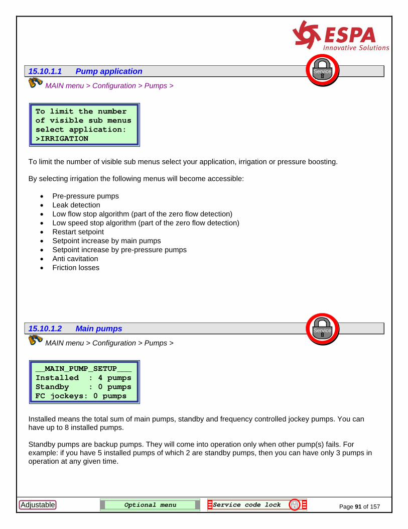
Page 91 of 157 Adjustable Optional menu Service code lock
15.10.1.1 Pump application
MAIN menu > Configuration > Pumps > To limit the number of visible sub menus select your application, irrigation or pressure boosting. By selecting irrigation the following menus will become accessible:
• Pre-pressure pumps • Leak detection • Low flow stop algorithm (part of the zero flow detection) • Low speed stop algorithm (part of the zero flow detection) • Restart setpoint • Setpoint increase by main pumps • Setpoint increase by pre-pressure pumps • Anti cavitation • Friction losses
15.10.1.2 Main pumps
MAIN menu > Configuration > Pumps > Installed means the total sum of main pumps, standby and frequency controlled jockey pumps. You can have up to 8 installed pumps. Standby pumps are backup pumps. They will come into operation only when other pump(s) fails. For example: if you have 5 installed pumps of which 2 are standby pumps, then you can have only 3 pumps in operation at any given time.
__MAIN_PUMP_SETUP___ Installed : 4 pumps Standby : 0 pumps FC jockeys: 0 pumps
Service
To limit the number of visible sub menus select application: >IRRIGATION
Service

Page 92 of 157 Adjustable Optional menu Service code lock
FC jockey pumps are frequency controlled jockey pumps that will supply small amounts of water (and leakages). They are the first pumps to come into operation and will be stopped as soon as one or more main pumps are started. Note that the installed number of pumps also includes the frequency controlled (FC) jockey pump(s). Consider the following pump setup…and let’s assume the pump sequence is straightforward: There are 6 pumps installed, of which 1 is standby and two are jockey pumps. So, in effect, there are 6 – 1 – 2 = 3 main pumps available for control, as indicated in the following diagram. As the flow increases upward from zero the following happens in each stage:
1. Frequency controlled jockey pump J1 is ramped up from minimum speed to 100% 2. Frequency controlled jockey pump J2 is ramped up from minimum speed to 100% 3. Main pump P3 is ramped up from minimum speed to 100% and the jockeys are ramped down slowly
and come to a stop 4. Main pump P4 is ramped up from minimum speed to 100% 5. Main pump P5 is ramped up from minimum speed to 100%. Note that P6 is standby so there is no
way it will come into operation, unless one of the other main pumps P3 to P5 fails. As the flow reduces we come through the following stages.
6. Main pump P5 is ramped down from 100% to minimum speed and stops. 7. Main pump P4 is ramped down from 100% to minimum speed and stops. 8. Frequency controlled jockey pumps J1 and J2 are ramped up from minimum speed to 100% and
take over P3 which is stopped. 9. Frequency controlled jockey pump J2is ramped down from 100% to minimum speed and stops. 10. Frequency controlled jockey pump J2is ramped down from 100% to minimum speed and stops.
__MAIN_PUMP_SETUP___ Installed : 6 pumps Standby : 1 pumps VLT jockeys: 2 pumps
Flow
P6 P5 J2 P4 P4 P4 J2 J1 J1 P3 P3 P3 P3 P3 J1 J1
Time
No pump 6(standby)
Stage 1 2 3 4 5 6 7 8 9 10
____PUMP_SEQUENCE___ J1 J2 P3 P4 P5 P6 1 2 3 4 5 6

Page 93 of 157 Adjustable Optional menu Service code lock
15.10.1.3 Main pumps curve
MAIN menu > Configuration > Pumps > Main pump setup > The actual pump head at zero flow is needed for minimum speed calculations. Note that actual pump head at zero flow is sometimes referred to as “the closed valve head pressure”. This figure must NOT take into account any positive or negative suction pressure. It is the value that you would normally retrieve from a pump curve in a catalogue. If you have frequency controlled jockey pumps, you need to specify also the flow at zero head. Since this number is not specified in any regular pump curve, you will have to extrapolate the pump curve and estimate the number like in the following example:
___MAIN_PUMP_CURVE__ Max head: >10.0 Bar If VLT jockey, flow at 0 head: 100.0 m3
Service
H (Bar)
Q (m3/h)
End of curve in catalogue Max head
to be specified
Flow at 0 head to be specified

Page 94 of 157 Adjustable Optional menu Service code lock
2 Q . Qmax
15.10.1.4 Jockey curve (FC)
MAIN menu > Configuration > Pumps > Main pump setup > . See previous section for an explanation of the required points. The jockey curve is required to calculate the switching point between jockey pump(s) and main lead pump.
To calculate this point the AUC3400 applies the infamous Hazen – Williams’ mathematical parabolic equation:
H = Hmax x [ 1 – ( ) ]
H (Bar)
Q (m3/h)
Extrapolate Jockey curve for flow Qj_max at zero pressure
Extrapolate main curve for flow Qm_max at zero pressure
End of 100% Jockey curve in catalogue
End of 100% main curve in catalogue
Example with 2 Jockey pumps.AUC3400 will calculate this curve.
This is the point that needs to be calculated for changing over between jockeys and
i
90% speed main curve (example)
82% MV speed main curve (example)
Setpoint (SV)
__VLT_JOCKEY_CURVE__ Max head: >12.0 Bar Extrapolated flow at 0 head: 022.0 m3
Service

Page 95 of 157 Adjustable Optional menu Service code lock
MV . 1000
HSV - Hinlet
x H m_max MV .1000
HSV - Hinlet H j_max
And from this equation we can derive the following equations. For the main speed controlled pump: Q = x Qm_max x 1-
( For the jockey pumps at full speed: Q = njockeys x Qj_max x 1- And finally, from all this the AUC3400 can calculate the switching over point: the Manipulated Value MV of the main lead pump, where it can stop the main pumps and continue to operate with just the jockey pump(s). So, all you need to do is specify 4 points:
1. Where the main pump curve starts 2. Where the main pump curve stops 3. Where the jockey pump curve starts 4. Where the main pump curve stops
Note: The Hazen – Williams’ equations is after all just an approximated pump curve. It will not be a 100% match and therefore the calculated MV switching point will also be an approximation. But, it will function nonetheless and you may even change the end points of the pumps curves at zero head to make a shift of the calculated MV switching point.
)2

Page 96 of 157 Adjustable Optional menu Service code lock
15.10.1.5 Pre-pressure pumps
MAIN menu > Configuration > Pumps > Pre-pressure pumps are used in irrigation application for supplying a constant positive suction pressure to the main pumps. Pre-pressure pumps, also referred to as pond pumps, serve to boost the inlet pressure of the main pumps within acceptable working conditions in certain applications. Without them the inlet pressure would fail to meet NPSH demands of the main pumps, with cavitation as a result. In most situations the pre-pressure pumps will be mounted in the suction pipe in parallel. The number of pre-pressure pump to be controlled can be specified in the above menu. Up to 8 pre-pressure pumps can be controlled by the AUC3400. Note: pre-pressure pumps will not be speed controlled by the AUC3400. Your only start options are direct on line or soft-start (which of course can still be done by means of frequency converters). The AUC3400 will operate the pre-pressure pumps through The ADAM modules are controlled over remote I/O modules such as the over the RS485 communication line. ADAM modules. These modules contain digital Up to two pumps can be connected per inputs for connection of run- and ADAM module. fail contacts and selector switches. There are transistor Up to four ADAM modules (8 pumps) can outputs available for starting / be controlled by the AUC3400. stopping pre-pressure pumps. 15.10.1.6 Pre-pressure setup
MAIN menu > Configuration > Pumps > If you have selected any pre-pressure pumps in the previous section, then this menu will become visible. In this menu you will find all options to control the operation of the pre-pressure pumps.
__PRE_PRESS_PUMPS___ Installed :>2
Service
___PRE-PRESS_SETUP__ >Requirement table Setpoint increase Timeout failure Main pump delay Low water detection AUTO switches
Service

15.10.1.6.1 Requirement table Service
MAIN menu > Configuration > Pumps > Pre-pressure setup >
Pre-pressure pump Requirement table: Main 1 2 3 4 5 6 Pre >1 1 1 2 2 2
The pre-pressure pump requirement table tells the AUC3400 what number of pre-pressure pumps to use in relation to the number of main pumps in operation. In the example above, there are six main pumps and two pre-pressure pumps available. To run the first three main pumps, we need a single pre-pressure pump. For main pump 4 to 6 we need two pre-pressure pumps. Note: in the above example a pre-pressure pump will be started before the first main pump. However, you can also start a main pump without a pre-pressure pump. The first “>1” in the above example would then be set to zero.
15.10.1.6.2 Setpoint increase
MAIN menu > Configuration > Pumps > Pre-pressure setup > In this example the setpoint will be increased by 0.5 Bar by each successive pre-pressure pump started. The purpose of this setpoint increase is to avoid hunting of the main pumps when an extra pre-pressure pump is brought into operation. What could happen without a setpoint increase is that the additional pre-pressure pump is capable by itself alone to supply that bit of extra water required to boost the pressure above the setpoint again. And of course the initial reason for starting that pre-pressure pump was because the pressure was dropping below the setpoint. So, without the setpoint increase the pre-pressure pump might start and stop continuously at intervals defined by the run on time of the pumps, because the pressure goes over and under the setpoint each time that pre-pressure pump is started and stopped. Note: in principle it is needless to specify a pressure increase for the first pre-pressure pump, as it is normally started before any of the main pumps is started. Only when one or more main pumps are allowed to run without any pre-pressure pump it makes sense to increase the setpoint for the first pre-pressure pump.
Service
Setp. Increase (Bar) 1=>0.0 2= 0.5
Page 97 of 157 Adjustable Optional menu Service code lock

15.10.1.6.3 Timeout failure Service
MAIN menu > Configuration > Pumps > Pre-pressure setup >
__TIMEOUT_FAILURE___ Input delay:>002 sec bypass relay (soft) starter: 05 sec.
The pre-pressure pumps can be started in various ways. But if you have a soft starter, you will need to be able to adjust the error timing of the starter. The input delay is the time that the run and thermal inputs should disappear before an alarm is raised. The bypass time is the time needed by a soft starter to start a motor and ramp it up to full speed. This is the time you also adjust at the soft starter front.
15.10.1.6.4 Main pump delay Service
MAIN menu > Configuration > Pumps > Pre-pressure setup >
__FILL_TIME_DELAYS__ 1=>010 2= 010
The pre-pressure pumps are often mounted in a separate leg in the suction pipe of the main pumps. Possibly this pipe leg has a separate air release valve and it may have to be filled by the pre-pressure pump prior to starting the main pump(s). The time it takes to fill the pipe should be specified in this menu. Note that when you have specified a time of ten seconds, like in the above example, it will take at least that time before a main pump is started and therefore the pressure might drop below the setpoint during that period.
15.10.1.6.5 Low water detection Service
MAIN menu > Configuration > Pumps > Pre-pressure setup >
Is the low water de-tected before or af-ter the pre-pressure pumps: >AFTER
Page 98 of 157 Adjustable Optional menu Service code lock

The inlet protection (switch or analogue signal) can be mounted before or after the pre-pressure pumps. Before: the pre-pressure pumps are protected against dry running. After: the main pumps are protected against dry running. However, the alarm will be released only after the filling times (previous section) are fulfilled.
15.10.1.6.6 AUTO switches Service
MAIN menu > Configuration > Pumps > Pre-pressure setup >
____AUTO SWITCHES___ AUTO-OFF-HAND switch for pre-press. pumps used: >YES
In the control menu you can put pumps into AUTO – OFF and HAND mode. However, if you have ordered a panel equipped with selector switches on the door for into AUTO – OFF and HAND outside the AUC3400, the controller needs to know the position of the external selector switches. In that case, select YES in this menu. Note: you will not be able to fully control the pumps in the control menu any more. The external selector switches prelate the control menu.
Page 99 of 157 Adjustable Optional menu Service code lock

Page 100 of 157 Adjustable Optional menu Service code lock
15.10.1.7 DOL Jockey pump
MAIN menu > Configuration > Pumps > If a DOL (Direct On Line) jockey pump is installed enter YES in this menu. When the main pumps are stopped the jockey pump will start when the pressure drops below 102% of the active setpoint level until the pressure reaches 104% of the setpoint.
15.10.1.8 Delay for lead pump
MAIN menu > Configuration > Pumps > If a DOL jockey pump is to be commissioned successfully, it may be required to hold of the main lead pump. Otherwise the main lead pump could start when, due to water of valve hammering, the pressure surges below the setpoint momentarily.
104%102%
Setpoint
H (Bar)
T(sec)
= Jockey pump runs = main pump runs (jockey pump is standby)
Jockey pump stops at 104% of setpoint
Jockey pump starts at 102% of setpoint
A main pump delay holds off the main pump (see next section)
____JOCKEY_SETUP____ Jockey pump: YES On below: 102 % Off above: 104 %
Service
__DELAY_LEAD_PUMP___ Start up delay for lead pump when pressure<set:> 2 sec
Service

Page 101 of 157 Adjustable Optional menu Service code lock
15.10.1.9 Run on pump timers
MAIN menu > Configuration > Pumps > If the controller commands a pump to stop, this timer will allow it to “run on” for the time specified above. The advantage of this run time is that a pump will continue to run at minimum speed and that it can be picked up by the AUC3400 speed controller very quickly as it becomes needed again, shortly after it had become obsolete.
____RUN ON TIME_____ Pumps run on for 0010 seconds.
Service

Page 102 of 157 Adjustable Optional menu Service code lock
15.10.2 Frequency converters
Quick setup > or MAIN menu > Configuration > The AUC3400 can control and program the Danfoss VLT series 2800 and 6000. For each connected pump you must select the FC model. The AUC3400 programs approx. 40 parameters in the FC in two setups. One setup is for the automatic control over the RS485 bus. The second setup is purely for manual control without the AUC3400. That means that as a customer, you can benefit from a high grade of redundancy. If you order selector switches, potentiometers and lamp indicators on the panel door, you are able to run the pumps in manual HAND operation, even if the AUC3400 completely fails. 15.10.2.1 Setup motor data
Quick setup > Frequency converters or MAIN menu > Configuration > Frequency converters > setup motor data
15.10.2.1.1 Motor 1
Quick setup > Frequency converters or MAIN menu > Configuration > Frequency converters > setup motor data FC drive is VLT2800, FC200, VLT6000, FCM300 (all Danfoss drives) or MGE (Grundfos).Kilo watts, voltage, current consumption and frequency can all be read from the motor plate.
__SETUP_MOTOR_DATA__ >Motor 1 Copy 1 to others Motor 2 Motor 3 Motor 4 Motor 5 Motor 6 Motor 7 Motor 8
______VLT_MENU______ >Setup motor data Program VLT’s
Service
Service
Service
__FC1_DRIVE_DATA___ FC drive:>VLT2800 015.00 kW 400 V 032.50 Amp 50 Hz
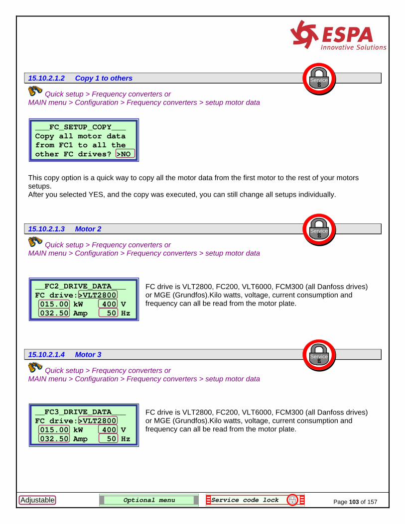
15.10.2.1.2 Copy 1 to others Service
Quick setup > Frequency converters or MAIN menu > Configuration > Frequency converters > setup motor data
___FC_SETUP_COPY___ Copy all motor data from FC1 to all the other FC drives? >NO
This copy option is a quick way to copy all the motor data from the first motor to the rest of your motors setups. After you selected YES, and the copy was executed, you can still change all setups individually.
15.10.2.1.3 Motor 2 Service
Quick setup > Frequency converters or MAIN menu > Configuration > Frequency converters > setup motor data FC drive is VLT2800, FC200, VLT6000, FCM300 (all Danfoss drives) or MGE (Grundfos).Kilo watts, voltage, current consumption and frequency can all be read from the motor plate.
__FC2_DRIVE_DATA___ FC drive:>VLT2800 015.00 kW 400 V 032.50 Amp 50 Hz
15.10.2.1.4 Motor 3
Quick setup > Frequency converters or MAIN menu > Configuration > Frequency converters > setup motor data FC drive is VLT2800, FC200, VLT6000, FCM300 (all Danfoss drives) or MGE (Grundfos).Kilo watts, voltage, current consumption and frequency can all be read from the motor plate.
Service
__FC3_DRIVE_DATA___ FC drive:>VLT2800 015.00 kW 400 V 032.50 Amp 50 Hz
Page 103 of 157 Adjustable Optional menu Service code lock

15.10.2.1.5 Motor 4 Service
Quick setup > Frequency converters or MAIN menu > Configuration > Frequency converters > setup motor data FC drive is VLT2800, FC200, VLT6000, FCM300 (all Danfoss drives) or MGE (Grundfos).Kilo watts, voltage, current consumption and frequency can all be read from the motor plate.
__FC4_DRIVE_DATA___ FC drive:>VLT2800 015.00 kW 400 V 032.50 Amp 50 Hz
15.10.2.1.6 Motor 5 Service
Quick setup > Frequency converters or MAIN menu > Configuration > Frequency converters > setup motor data FC drive is VLT2800, FC200, VLT6000, FCM300 (all Danfoss drives) or MGE (Grundfos).Kilo watts, voltage, current consumption and frequency can all be read from the motor plate.
__FC5_DRIVE_DATA___ FC drive:>VLT2800 015.00 kW 400 V 032.50 Amp 50 Hz
15.10.2.1.7 Motor 6
Quick setup > Frequency converters or MAIN menu > Configuration > Frequency converters > setup motor data FC drive is VLT2800, FC200, VLT6000, FCM300 (all Danfoss drives) or MGE (Grundfos).Kilo watts, voltage, current consumption and frequency can all be read from the motor plate.
Service
__FC6_DRIVE_DATA___ FC drive:>VLT2800 015.00 kW 400 V 032.50 Amp 50 Hz
Page 104 of 157 Adjustable Optional menu Service code lock

Page 105 of 157 Adjustable Optional menu Service code lock
15.10.2.1.8 Motor 7
Quick setup > Frequency converters or MAIN menu > Configuration > Frequency converters > setup motor data FC drive is VLT2800, FC200, VLT6000, FCM300 (all Danfoss drives) or MGE (Grundfos).Kilo watts, voltage, current consumption and frequency can all be read from the motor plate.
15.10.2.1.9 Motor 8
Quick setup > Frequency converters or MAIN menu > Configuration > Frequency converters > setup motor data FC drive is VLT2800, FC200, VLT6000, FCM300 (all Danfoss drives) or MGE (Grundfos).Kilo watts, voltage, current consumption and frequency can all be read from the motor plate. 15.10.2.2 Program FC
Quick setup > Frequency converters or MAIN menu > Configuration > Frequency converters In this menu you can instruct the AUC3400 to program a single or all frequency converters (Danfoss VLTs). The AUC3400 will program two different setups in each selected FC. Each of those setups contains approximately 22 parameters. One setup is for the automatic control over the RS485 bus by the AUC3400. The second setup is purely for manual control without the AUC3400. Refer to section 17 and 19 for the parameter setups of Danfoss VLTs by the AUC3400.
Service
Service
____PROGRAM_VLT_____ Select VLT :>None
Service
__FC7_DRIVE_DATA___ FC drive:>VLT2800 015.00 kW 400 V 032.50 Amp 50 Hz
__FC8_DRIVE_DATA___ FC drive:>VLT2800 015.00 kW 400 V 032.50 Amp 50 Hz

Page 106 of 157 Adjustable Optional menu Service code lock
If you want to program a FC you should make sure that FC is standby, that is: powered on and not running a motor. To start the programming, select a FC or all FCs: After you made a selection, for example FC4 and pressed enter the programming starts:
The menu number being programmed will count up quickly and once all the menus are programmed the following will show: However, if during the programming an error is detected by the AUC3400, it will show briefly in which FC and menu programming went wrong and it will increment the error counter.
____PROGRAM_FC_____ Select FC : FC4
4 Programming : FCMenu number : 5
Menu number being programmed in the FC. See section 17 and 19 for a list of
FC number being programmed in the FC.
____PROGRAM_VLT_____ Select VLT :>None None
ALL FC1 FC2 FC3 FC4 FC5 FC6 FC7 FC8
____PROGRAM_FC_____ Select FC : >None Ready! Errors : 0

Page 107 of 157 Adjustable Optional menu Service code lock
If you program all FCs, by selecting “ALL”, the AUC3400 will start by FC 1 and go through all of your installed FC menus one by one. Note that you can program a standby FC even when the pump control is operating and other pumps are running. 15.10.3 Sensors
MAIN menu > Configuration > Here you configure items related to the sensors / transmitters. 15.10.3.1 Discharge pressure
MAIN menu > Configuration > Sensors > Here you configure items related to the discharge sensor.
15.10.3.1.1 Sensor range
MAIN menu > Configuration > Sensors > Discharge pressure
Range is the value specified by the sensor. Actual is the actual measured pressure in relation to range. 4 – 20 mA is YES where you connect a 4 – 20 mA sensor.
_______SENSORS______ >Discharge pressure Suction pressure Remote setpoint Flow kWh High water switch
__DISCHARGE_SENSOR__ >Sensor range High alarm High alarm reset Low alarm Low alarm reset Low alarm override High alarm switch
Service
Service
Service
__DISCHARGE_SENSOR__ Range: 10.0 Bar Actual: 5.0 Bar 4 – 20 mA : YES

15.10.3.1.2 High alarm Service
MAIN menu > Configuration > Sensors > Discharge pressure
__DISCHARGE_SENSOR__ High discharge pressure alarm set at: >05.0 Bar
If the discharge pressure reaches the high pressure limit and a shut down of the system is created.
15.10.3.1.3 High alarm reset Service
MAIN menu > Configuration > Sensors > Discharge pressure
__DISCHARGE_SENSOR__ High pressure alarm automatically resets after: >060 seconds
If the pressure returns below the high pressure limit after a shut down, the AUC3400 will automatically restart the pump(s) after the specified period.
15.10.3.1.4 Low alarm
MAIN menu > Configuration > Sensors > Discharge pressure
Service
__DISCHARGE_SENSOR__Low discharge press.
setting: 00.0 BarDelay: 001 sec
If the discharge pressure drops below the low pressure limit for the specified time delay, the system will be shut down.
Page 108 of 157 Adjustable Optional menu Service code lock

15.10.3.1.5 Low alarm reset
MAIN menu > Configuration > Sensors > Discharge pressure If the discharge pressure drops below the low pressure limit the system will be shut down. Here you can control how the AUC3400 should respond next. If the auto reset number specified here is set to zero, the AUC3400 will not resume operation again. If set to a number which is not zero, in this example the number 3, then the AUC3400 will automatically try to resume operation again for 3 times a day (each day at midnight the counter is reset). The delay specifies the time delay between the time the low pressure alarm was raised and the time that auto reset is tried.
15.10.3.1.6 Low alarm override
MAIN menu > Configuration > Sensors > Discharge pressure The low pressure shut down condition is overridden during start-up of the system for the time specified here. It is NOT overridden during filling of the pipes. Therefore, take into consideration the time it may take to fill up the pipes at a low setpoint (refer to section15.7.4).
15.10.3.1.7 High alarm switch
MAIN menu > Configuration > Sensors > Discharge pressure Beside the high discharge pressure limit that you specified as an analogue value, you can also have a pressure switch input [digital]. When activated the switch will triggers the same high discharge alarm as the analogue input.
Service
Service
__LOW_DISCHARGE____ Disable low pressure alarm during startup for: >0030 seconds
_DISCHARGE_SWITCH__ Do you have a high discharge pressure switch? >NO
Service
__DISCHARGE_SENSOR__ Low pressure alarm auto resets? 3 after: 50 seconds
Page 109 of 157 Adjustable Optional menu Service code lock

Page 110 of 157 Adjustable Optional menu Service code lock
15.10.3.2 Suction pressure
MAIN menu > Configuration > Sensors > Here you configure items related to the suction sensor.
15.10.3.2.1 Enable
MAIN menu > Configuration > Sensors > Suction sensor Together with the nominal pump head, the suction pressure is needed for minimum speed calculations and a correct calculation of the speed adjustments. If you do not have a suction sensor, specify the correct fixed suction pressure.
IMPORTANT: Failing to specify the correct inlet pressure value is the number one reason for bad pressure control! It will create oscillation and zero flow detection will fail!
15.10.3.2.2 Sensor range
MAIN menu > Configuration > Sensors > Suction sensor
00.0 to 01.00 is the range of the sensor. Actual is the actual measured pressure in relation to range. 4 – 20 mA is YES where you connect a 4 – 20 mA sensor.
Note that you may specify any range like -2 to +2 bar.
__SUCTION_SENSOR___ >Enable Range Low alarm Low alarm reset Low alarm override Low alarm switch
___SUCTION_SENSOR__ Enable: >NO If no, or failure use: 00.00 Bar.
___SUCTION_SENSOR___ 00.0 to 01.0 Bar Actual: 0.0 Bar 4 - 20 mA: YES
Service
Service
Service

15.10.3.2.3 Low alarm Service
MAIN menu > Configuration > Sensors > Suction sensor
___SUCTION_SENSOR__ Low inlet pressure setting: 00.0 Bar
If the suction pressure drops below the low pressure limit for one second, a shut down condition is created.
15.10.3.2.4 Low alarm reset Service
MAIN menu > Configuration > Sensors > Suction sensor
___SUCTION_SENSOR___ Low pressure alarm automatically resets after: >060 seconds
If the pressure returns above the low pressure limit the system will restart after the period that is specified here.
15.10.3.2.5 Low alarm override Service
MAIN menu > Configuration > Sensors > Suction sensor
__SUCTION_OVERRIDE__ Enable HAND opera-
tion of pumps when suction fails ? >NO
When a low suction alarm is active you cannot operate the pumps, not even in HAND mode. However, if the problem is created by a defect in the sensor you may want to be able to control the pumps in HAND mode. If so, select YES in this menu option.
Page 111 of 157 Adjustable Optional menu Service code lock

Page 112 of 157 Adjustable Optional menu Service code lock
15.10.3.2.6 Low alarm switch
MAIN menu > Configuration > Sensors > Suction sensor Beside the low suction pressure limit that you specified as an analogue value, you can also have a pressure switch input [digital]. When activated the switch will create the same low suction alarm as the analogue input. 15.10.3.3 Remote setpoint
MAIN menu > Configuration > Sensors > In the remote setpoint menu you can enable a remote setpoint. The external setpoint reference value is obtained from an analogue input. An external device can thus change the actual setpoint into a desired setting by applying the corresponding analogue value to the AUC3400 analogue input. The remote setpoint needs to be enabled both in the software and in the hardware. In the software the remote setpoint is enabled as described in the following section. In the hardware the remote setpoint is enabled by a digital switch that is connected to the analogue input at terminal 22 through a resistor (2 kOhms). Only if the switch is activated, so is the external setpoint.
___REMOTE_SETPOINT__ Enable Range
Service
Service
___SUCTION SWITCH___ Do you have a low
ure suction pressswitch? >YES

Page 113 of 157 Adjustable Optional menu Service code lock
15.10.3.3.1 Enable
MAIN menu > Configuration > Sensors > Remote setpoint > The remote setpoint option can be enabled by changing NO into YES. In case of a wire break from the remote setpoint reference, the AUC3400 will fall back to the local setpoint (or quick setpoint) if you leave the bottom line option YES. Otherwise the controller will shut down the pumps.
15.10.3.3.2 Range
MAIN menu > Configuration > Sensors > Remote setpoint >
10.00 is the range of the remote setpoint reference. Actual is the actual external setpoint in relation to range. 4 – 20 mA is YES where you connect a 4 – 20 mA sensor.
15.10.3.4 Flow
MAIN menu > Configuration > Sensors > In the flow meters menu you can select one of three sources for flow measuring:
1. Rate flow meter, with an analogue output signal 2. Totalising flow meter, with a pulsed digital output signal
____FLOW_METERS____ >Analog flow meter Pulsed flow meter Virtual flow meter Pumped volume Show flow in headup Flow threshold
Service
Service
Service
___REMOTE_SETPOINT__ Enable: >NO
If case of failure use local setp.: YES
___REMOTE_SETPOINT__ Range: >10.0 Bar Value: 6.3 Ba4 – 20 mA: NO
r

3. Virtual flow meter, an internally calculated flow value based on the pump curve. From any of these flow sources the following flow measurements can be obtained:
1. Flow rate in m3/h 2. Total pumped volume in m3 3. Periodic pumped volume in m3
15.10.3.4.1 Analogue flow meter Service
MAIN menu > Configuration > Sensors > Flow
_ANALOG_FLOW_METER__ Enable: >NO Range : 001.0 m3/h 4-20mA: NO
If you have a flow meter with an analogue output connected to the AUC3400 you can configure it here. If you have a flow meter with an pulse output connected to the AUC3400 (for flow rate), proceed to the next section.
15.10.3.4.2 Pulse flow meter Service
MAIN menu > Configuration > Sensors > Flow
_FLOW_RATE_BY_PULSE_ Enable : NO K-factor: 001.0000 Compens.: 001.0000
If you have a flow meter with an pulse output connected to the AUC3400 (for flow rate) select yes. To set up the flow rate you need to specify the K-factor which will be specified by the flow meter manufacturer and possibly a compensation for the placement of the flow meter in the pipe.
15.10.3.4.3 Virtual flow Service
MAIN menu > Configuration > Sensors > Flow
_VIRTUAL_FLOW_METER_ >Record pump curve Pump curve points Enable virtual flow Show real/virtual
Page 114 of 157 Adjustable Optional menu Service code lock

The virtual flow meter option offers a way to display flow without actually measuring the flow.
15.10.3.4.3.1 Record pump curve Service
MAIN menu > Configuration > Sensors > Flow > Virtual flow
____VIRTUAL_FLOW____ Record 1-6 (Up/Down) Enter = store point DH= 5.931 Q= 57.00
In this menu you can record a pump curve when you run a pump with an external flow meter connected to the analogue input. You might do this once in the workshop where you have a flow meter with an available analogue output. The recording is a set of 6 points of pressure and flow. You must record 6 points before you enable virtual flow! With the six points the AUC3400 will generate a pump curve using polynomial mathematics. Using the recorded pump curve enables the AUC to calculate the flow just by reading the pressure. For more information contact your supplier.
15.10.3.4.3.2 Pump curve points Service
MAIN menu > Configuration > Sensors > Flow > Virtual flow
__PUMP_CURVE_POINTS_ Curve points 1-3 Curve points 4-6
15.10.3.4.3.2.1 Pump curve points 1-3
MAIN menu > Configuration > Sensors > Flow > Virtual flow > Curve points 1-3
Service
__Points_1_to_3____ 1 H= 05.93 Q= 057.00 2 H= 07.40 Q= 048.00 3 H= 08.93 Q= 035.00
Page 115 of 157 Adjustable Optional menu Service code lock

15.10.3.4.3.2.2 Pump curve points 4-6
MAIN menu > Configuration > Sensors > Flow > Virtual flow > Curve points 4-6
Service
__Points_4_to_6____ 4 H= 06.65 Q= 025.00 5 H= 10.00 Q= 013.00 6 H= 10.10 Q= 000.00
In these menus you view the recorded pump curve or you can enter the points yourself, right out a data sheet or pump curve. Important note: - use equal distanced flow points.
- If the pump curve has a maximum head on a flow other than 0, make sure you record a point at that point.
- See the above example setting. - For more information contact your supplier.
1
2
3
46
H Bar
5
Q m3/h
Page 116 of 157 Adjustable Optional menu Service code lock

Page 117 of 157 Adjustable Optional menu Service code lock
The above figure show what the sequence of recorded point is. They also show the point are taken at equal distance and that the last point should be taken at the highest pressure value, not necessarily zero flow.
15.10.3.4.3.3 Show real/virtual
MAIN menu > Configuration > Sensors > Flow > Virtual flow This menu shows the real and virtual flow, so you can compare the virtual flow curve against the real flow curve of a flow meter.
1
2
3
56
4
H Bar
Q m3/h
The final point is taken here since the pressure is at it’s peak.
__FLOW_COMPARISON__ Analog flow = 0.49 Virtual flow= 0.00 Dhb= 0.04 dhm= 0.4
Service

15.10.3.4.4 Pumped volume Service
MAIN menu > Configuration > Sensors > Flow
___PUMPED_VOLUME___ Calc.from rate: >YES If digital input,one pulse = 00.10000 m3
The pumped volume counters (total and periodical) need a digital input from a totalising pulsed flow meter or can be derived from the analogue signals from a flow meter with an analogue output or from the internal virtual flow meter. In case you have a digital input from a totalising pulsed flow meter, select NO and select the conversion rate at the bottom line, otherwise select YES.
15.10.3.4.5 Show at head up Service
MAIN menu > Configuration > Sensors > Flow
____HEAD_UP_FLOW____ Show flow reading in the default head up Display? NO
The default head up display normally shows MEFX – VX.X on the third line. If you are using a flow meter, you can display it on the third line instead of the MEFX text. The question in the bottom line refers to the true flow reading from an external flow meter (NO) or to the calculated virtual flow (YES).
15.10.3.4.6 Flow threshold Service
MAIN menu > Configuration > Sensors > Flow
___FLOW_THRESHOLD___ High flow threshold setting:>9999.0 m3/h Delay: 005 sec
Page 118 of 157 Adjustable Optional menu Service code lock

Page 119 of 157 Adjustable Optional menu Service code lock
With this option you can have a high flow alarm and signal the alarm at the AUC3400 terminal designated Flow Threshold (potential free contacts). 15.10.3.5 kWh
MAIN menu > Configuration > Sensors > If you enable the kWh meter, the readings will appear in the head up displays and in the status menu. There, you will also be able to reset the periodical counter. Refer to section 15.1.9. The next thing is to select whether you have an external pulsing kWh meter that you want to connect. The external kWh meter should have its digital output contact connected to the appropriate AUC3400 terminal. If you do not have an external kWh meter, the AUC3400 will calculate the kWh consumption by processing the kW readings from the frequency converters. Note that this calculated number does not include power consumption from other components such as relays, the AUC3400 and direct on line operated pre-pressure and jockey pumps.
15.10.3.6 High water switch
MAIN menu > Configuration > Sensors > If you have an optional external level controller which can signal a high water level in the well or possibly in the control room, you may enable this menu option. An alarm will be raised if the concerned input is broken.
_____kWh_METER______ Enable: >NO Pulsed meter: NO pulse =>00.10000 kWh
Service
__HIGH WATER SWITCH_ Enable? NO Alarm delay: 5 sec.

Page 120 of 157 Adjustable Optional menu Service code lock
15.10.4 Controller
MAIN menu > Configuration > In the control menu you will items related to the control behaviour of the AUC3400. 15.10.4.1 Sample time
MAIN menu > Configuration > Controller The AUC3400 has an internal sample time in which the control adjustments are calculated. For normal installations you will never need to adjust this sample time. It will only become interesting in systems with a response lag or dead time, for example heating systems. Always contact Aqualectra before attempting to adjust this setting. 15.10.4.2 Control speed
MAIN menu > Configuration > Controller
_____CONTROLLER_____ >Sample time Control speed -> differentiator Minimum speed Pressure filters Anti cavitation Friction losses Pump simulator
Service
Service
Service
_____SAMPLE TIME____ Note:use value big- ger than 50 for slow system only:>0050 mS
___CONTROL_SPEED____ AUC 3400:>05.0 sec VLT ramp: 00.5 sec (VLT less than AUC!)

Page 121 of 157 Adjustable Optional menu Service code lock
The control speed specifies how fast or how slow the AUC3400 is allowed to control the pressure to the setpoint by speeding up and down the pump. This is a very important control menu, since the speed of the AUC3400 control should be in line with the hydraulic characteristics of your specified pump application. In this menu you adjust the AUC3400 control speed and the frequency converter ramp time (Danfoss VLT ramp) which will be programmed by the AUC3400 in the FC when your order it to (refer to section 15.10.2). The following figure shows what the two ramp parameters are about:
The figure shows what happens when one pump operates at maximum speed and the flow demand increases. The pressure will drop and the AUC3400 will start the second pump. The second pump ramps up to minimum speed following the FC ramp setting (fast). Then, at minimum speed, the pump ramps up following the AUC3400 ramp (slow). The reason for using these two different ramp timers lies in the fact that up to minimum speed the second pump will not affect the pressure. Therefore it can be allowed to ramp up to minimum speed as fast as possible.
10%
H (Bar)
Q (m3/h)20%
30%
40%
50%
60%
70%
84% Minimum speed
90%
Pressure
FAST This part of ramping up the pump speed is defined by the VLT ramp
SLOW This part of ramping up the pump speed is defined by the AUC3400 ramp
One pump at full speed
Two pumps at full speed

Page 122 of 157 Adjustable Optional menu Service code lock
Even in a (very) slow system the AUC3400 can respond quickly that way. Instead of having to ramp up the pump slowly from zero to the minimum speed, it can pickup the pressure almost instantly. So, in a slow system, you normally slow down only the AUC3400 ramp time! 15.10.4.3 Differentiator
MAIN menu > Configuration > Controller The differentiator is an option that should be applied with great care. A differentiator counter acts on pressure changes. The faster the pressure changes, the faster the differentiator acts in the opposite direction. It can make a better control in that it allows a faster control with less overshoot, but it can also easily destroy the pressure control if there is noise on the discharge pressure sensor signal (which it interprets to be fast pressure shifts). By default this option is disabled (zeroed). It makes sense to use this option in case you have a slow system where you may have overshoot in the pressure created by pressure reflections in the pipe line. Otherwise we discourage the use of the differentiator. 15.10.4.4 Minimum speed
MAIN menu > Configuration > Controller The minimum speed is automatically calculated by the AUC3400. Input parameters are pumps head, setpoint and suction pressure. However, because pumps do not always have equal performances and inlet pressure may vary, the minimum speed calculated might prove to be too critical. That could lead to problems such as hunting pumps (when an extra pump is needed) or that the minimum speed at very low flow rates is too high and therefore would trigger the zero flow mechanism in adversely. To avoid these situations the AUC3400 comes default with a –2% offset allowing for small variations. If you still encounter problems lower the offset. Otherwise you might also increase the fixed inlet pressure (section 15.10.3.2.1) or increase the zero flow nominal pump head (section 15.10.1.3).
Service
___MINIMUM_SPEED____ Calculated: 68.7 %
Offset to be used inthis system: -2 %
___DIFFERENTIATOR___ Control weight of the differentiator speed: >0.0
Service

Page 123 of 157 Adjustable Optional menu Service code lock
15.10.4.5 Pressure filters
MAIN menu > Configuration > Controller This menu controls the following: • Damping: this is the filter applied to the analogue input signals from the various transmitters. If you have
a system with a lot of vibration you may need to increase the damping to create a more stable control.
• Dead band: this is the tolerance around the setpoint where the measured pressure is allowed to move, without the AUC trying to correct the speed to match the setpoint. Again, if you have troubles caused by vibrations, increase this value. Note: if you increase the dead band to let’s say 0.5 bar, you would never be able to create the pressure boost of 5% at zero flow. Therefore, the dead band during pressure boost will always be set to 0.05 Bar by the AUC3400, so that the boost is really created. Thus, you are allowed to create a wide dead band.
• Fast Fuzzy Wise: this will enable the Fuzzy Wise pressure correction algorithm to make very fast speed corrections when the pressure rises faster than the AUC3400 control ramp allows the speed of the pumps to go down. If enabled, the Fast Fuzzy Wise algorithm is activated when the pressure is 5% higher than the setpoint. Fast Fuzzy can do miracles in case your application should have a slow and stable pressure control with long setpoint and control ramp timers, but where it should ramp down the pumps very fast when a big valve is suddenly closed in the discharge pipe. Fast Fuzzy works only in one direction (down) so it will not cause oscillation due to undershoot. Note: refer to section 9 for detailed description on Fuzzy Wise control.
Service
__PRESSURE_FILTERS__ Damping: 15
r Dead band: 0.05 baFast Fuzzy Wise: NO

Page 124 of 157 Adjustable Optional menu Service code lock
15.10.4.6 Anti cavitation mode
MAIN menu > Configuration > Controller Normally the pumps are controlled in cascading. That is, when the first lead pump reaches 100% the next one is started at minimum speed and then the speed of that second pump is controlled, whereas the first pump remains at 100% speed. In anti cavitation mode a number of pumps are started at the same time and are controlled at the same speed in parallel, effectively creating one big pump and avoiding pumps to run off their pump curves and avoiding cavitation.
15.10.4.6.1 Anti cavitation
MAIN menu > Configuration > Controller > Anti cavitation Normally, in the default cascading control mode, pumps are started one by one. If you enable cavitation mode by selecting YES and specify 2 pumps to be run in parallel the following will happen:
- When the system is started up after a power failure or a shut down failure the start up setpoint (default 2 Bar) will be controlled with two pumps instead of one pump at 50 % default. This is to fill the pipes.
- After the pipes are filled the 2 pump run in parallel at the same speed. - When the two pumps reach 105% the third pump is started at minimum speed. It will be
controlled up until the setpoint is reached (for example at 87% speed) and the first two pumps running in parallel run at 100 %.
- When the third pump reaches 105% the fourth pump is started at minimum speed. It will be controlled up until the setpoint is reached (for example at 83% speed) and the first three pumps run at 100 %.
If you select 3 pump pumps to be run in parallel the system will start with three pumps in parallel. If you select 4 pump pumps to be run in parallel the system will start with four pumps in parallel. All this is true until you enable automatic detection mode:
__PUMP_CONTROL_MODE_ Anti cavitation + auto detection + auto status
Service
Service
__CAVITATION_MODE___ Enable mode: NO Pumps to be run in parallel: 1

15.10.4.6.2 Anti cavitation + auto detection Service
MAIN menu > Configuration > Controller > Anti cavitation
__CAVITATION_MODE___ Enable automatic detection mode: NO Max. flow: 080 m3/h
If you enable automatic detection mode the AUC3400 will calculate when the pump runs of their curve and cavitation becomes a problem. It will calculate this cavitation point at all speeds, not just at full speed. Therefore you need to enable the virtual flow option, refer to section 15.10.3.4.3. To setup automatic cavitation detection proceed as follows:
- Enable virtual flow by entering or recording a pump curve (to section 15.10.3.4.3). - Run a single pump in manual at full speed and listen while gradually creating more flow
when the pump starts to cavitate. Enter this cavitation flow (or better a little lower) as the maximum flow per pump in this menu. Optionally you can also directly specify the max. flow just by reading the pump curve in the catalogue.
15.10.4.6.3 Anti cavitation + auto status Service
MAIN menu > Configuration > Controller > Anti cavitation
_CAVITATION_STATUS_ Cav.point: 80.0 m3/h Q at 100%: 65.9 m3/h Pumps in parallel: 2
If you enabled automatic cavitation mode the AUC3400 will calculated at any speed what the flow of each pump would be at full speed and compare it with the maximum flow per pump allowed. If the flow of any pump passes the maximum flow an extra pump will be started and it will run in parallel. That means that pump will probable not be able up to full speed anymore to avoid cavitation! This menu show the status, the second line shows the specified maximum flow. The third line shows the calculated flow per pump at 100% speed. The bottom line shows the number of pump required to run parallel. When pumps are running in parallel and the flow reduces the AUC3400 calculates the exact point where pumps can be stopped without causing cavitation for the pumps left running. For further information contact your supplier.
Page 125 of 157 Adjustable Optional menu Service code lock
Service

Page 126 of 157 Adjustable Optional menu Service code lock
15.10.4.7 Friction losses
MAIN menu > Configuration > Controller If you have virtual flow or true flow readings enabled, you can enable good and reliable friction loss compensation. All the underscored fields can be edited. Damping means a filter value to avoid, if necessary, up and down hunting of the setpoint. An example of how to setup friction loss compensation: In this case the setpoint at zero flow will be 70% of the specified setpoint. At 95 m3/h the setpoint will be 98%.
_FRICT_COMPENSATION_ At 0 m3/h: 100% At 0100 m3/h: 100% Damping factor: 002
_FRICT_COMPENSATION_ At 0 m3/h: 070% At 0095 m3/h: 098% Damping factor: 002
H (Bar)
Q (m3/h)
70% of setpoint
Setpoint (100%)
Flow depending setpoint line, calculated by the AUC3400. Compensated for friction losses.
98% of setpoint
95 m3/h

Page 127 of 157 Adjustable Optional menu Service code lock
15.10.4.8 Pump simulator
MAIN menu > Configuration > Controller Supplier: when you want to simulate the AUC3400 controller in the workshop with all input options enabled you can run the build in pump set simulator. The discharge pressure input can be used to connect a 4-20 mA flow valve simulator. The AUC will control and behave as if it was controlling the pumps and pressure in reality. Note: if you want to keep running the simulator after a power failure disable select YES at the bottom line. By default the simulator will be disabled after a power failure to avoid problems.
Service
__PUMP_SIMULATOR___ Enable: YES
power Disable after reset? YES

15.10.5 Modem Service
MAIN menu > Configuration > The AUC3400, is packed with a sophisticated set of modem commands and tools. They allow you to:
• Connect remotely by a PC to the AUC3400 over a modem and operate he menu, view all status graphically and make trends. This has been explained earlier in this manual.
• Receive alarm SMS messages on your mobile phone (refer to following sections).
• Enable a call cycle, so that up to 5 different recipients can receive alarm SMS messages. The last recipient to receive an SMS should send an acknowledgement or reset SMS TO the AUC3400. If not, the AUC3400 will relay the alarm SMS messages to the next recipients! (refer to following sections).
• Sent acknowledgment SMS to the AUC3400. This is what you use if you want to keep the AUC3400 from relaying the alarm SMS messages to other recipients. However, pending alarms will NOT reset and the AUC3400 may not resume operation of the pumps when there is a blocking alarm (like multiple low suction pressures). To acknowledge pending alarms: on your mobile phone type the following SMS: A0001 and send it the mobile telephone number of the modem connected to the AUC3400. Notes: - this is not the data number, but the regular voice number. - the A in S0001 stands for “Acknowledge” - the 0001 in S0001 stands for the user login code, which might be changed by the end customer. You cannot use the service code, so that the end customer remains in control of who can and cannot access the AUC3400. - If the user code is changed to, let’s say 3456, the SMS would become A3456.
• Sent a reset SMS to the AUC3400. This is what you use if you want to acknowledge AND reset pending alarms. To acknowledge pending alarms: on your mobile phone type the following SMS: R0001 and send it the mobile telephone number of the modem connected to the AUC3400.
Page 128 of 157 Adjustable Optional menu Service code lock

• Sent a status inquiry SMS to the AUC3400. On your mobile phone type the following SMS: S0001 and send it the mobile telephone number of the modem connected to the AUC3400. The AUC3400 will reply by sending you the following status update SMS: < Name of the site Setpoint: 5.00 Bar Pressure: 5.01 Bar Suction: 0.54 Bar Flow: 89,7 m3/h Speed: 175,7 % Min.speed: 68,7 % Pumps: RRSS > Note: the AUC3400 will retrieve your mobile telephone number from your inquiry SMS and send back the reply SMS. So, your number does not have to be set into recipients list, any mobile phone can be used!
Page 129 of 157 Adjustable Optional menu Service code lock
Sent a history inquiry SMS to the AUC3400. On your mobile phone type the following SMS: H0001 and send it the mobile telephone number of the modem connected to the AUC3400. The AUC3400 will reply by sending you up to 5 SMS messages, containing the lat 10 entries in the alarm history. Each SMS you receive will look like the following: < Name of the site (Alarm 1 of 10) - Pump 4 failure Time: 08:23:46 Date: 22-07-2007 (Alarm 2 of 10) - Power failure Time: 10:55:45 Date: 21-07-2007 >

Page 130 of 157 Adjustable Optional menu Service code lock
The modem menu contains the following: Note that the number of menu’s appearing for recipient numbers depend on the number of total recipients defined in the concerned menu. 15.10.5.1 Modem selection
MAIN menu > Configuration > Modem > If you have a the TC35i wireless GSM modem connected you should set this options to YES. If you don’t, the modem will probably malfunction due to a constant data stream coming from the AUC3400. This data is display information (the text to be displayed). Setting this option to YES will inhibit the data stream. When a remote PC running the AUC3400.exe program contacts the AUC3400 over the modem the data stream will be enabled by codes generated by the PC program. AUC3400 detects these codes and will then enable communication. 15.10.5.2 SMS header text
MAIN menu > Configuration > Modem >
___GSM_MODEM_MENU___ Modem selection SMS header text Total of recipients Recipient number 1 Recipient number 2 Recipient number 3 Recipient number 4 Recipient number 5 Enable alarm SMS Enable call cycle Initialize modem
Service
Service
__MODEM_SELECTION___ Use TC35i modem: >NO
__SMS_HEADER_TEXT__ Edit the next line:
AAAAAAAAAAAAAAAAA A

Page 131 of 157 Adjustable Optional menu
Service code lock
If you are going to receive SMS alarm text messages they will be preceded by the text specified here. Type the name or location of your pump site here, so the receiver of the SMS will now the location of the pump set. 15.10.5.3 Total of recipients
MAIN menu > Configuration > Modem > If you are going to enable an SMS call cycle set the number of SMS recipients here. An SMS call cycle may be used when you require that alarm SMS messages need to be remotely acknowledged and/or reset. That is possible by sending an SMS message TO your AUC3400 controller! Upon receiving of a proper acknowledgement or reset SMS within a predetermined response time, the AUC3400 will not “call” other recipients to relay the alarm SMS message again. However, if no reset or acknowledge SMS is received by the AUC3400 within the response time, the AUC3400 will resend the SMS error messages to the next recipient in the list. If this next recipient responds to the AUC3400 by sending an acknowledgment or reset SMS the AUC3400 will cease sending SMS messages (until a new alarm is raised). 15.10.5.4 Recipient number 1
MAIN menu > Configuration > Modem > Enter the name and mobile phone number of the prime recipient for alarm SMS messages here. Also specify the length of the telephone number, which may differ per country, area or provider.
Service
Service
__SMS_RECIPIENT no1_ Name: P. Gerritsen no: +4470000000000 Number of digits: 13
Service
___SMS_RECIPIENTS__ MS Total number of S
Recipients to be activated: >5

Page 132 of 157 Adjustable Optional menu Service code lock
15.10.5.5 Recipient number 2
MAIN menu > Configuration > Modem > Note: this is an optional menu. If your have specified less than 2 recipients, this menu will not appear. Enter the name and mobile phone number of the next recipient for alarm SMS messages here. This will be the next recipient to receive alarm SMS messages when the prime receiver fails to reset or acknowledge the alarms with the sets response time. Also specify the length of the telephone number, which may differ per country, area or provider.
__SMS_RECIPIENT no2_ Name: AAAAAAAAAAAA no: +4470000000000 Number of digits: 13

Page 133 of 157 Adjustable Optional menu Service code lock
15.10.5.6 Recipient number 3
MAIN menu > Configuration > Modem > Note: this is an optional menu. If your have specified less than 3 recipients, this menu will not appear. Enter the name and mobile phone number of the third recipient for alarm SMS messages here. This will be the next recipient to receive alarm SMS messages when the second receiver fails to reset or acknowledge the alarms with the sets response time. Also specify the length of the telephone number, which may differ per country, area or provider. 15.10.5.7 Recipient number 4
MAIN menu > Configuration > Modem > Note: this is an optional menu. If your have specified less than 4 recipients, this menu will not appear. Enter the name and mobile phone number of the fourth recipient for alarm SMS messages here. This will be the next recipient to receive alarm SMS messages when the third receiver fails to reset or acknowledge the alarms with the sets response time. Also specify the length of the telephone number, which may differ per country, area or provider.
Service
__SMS_RECIPIENT no3_ Name: AAAAAAAAAAAA no: +4470000000000 Number of digits: 13
Service
__SMS_RECIPIENT no4_ Name: AAAAAAAAAAAA no: +4470000000000 Number of digits: 13

Page 134 of 157 Adjustable Optional menu Service code lock
15.10.5.8 Recipient number 5
MAIN menu > Configuration > Modem > Note: this is an optional menu. If your have specified less than 5 recipients, this menu will not appear. Enter the name and mobile phone number of the fifth recipient for alarm SMS messages here. This will be the next recipient to receive alarm SMS messages when the fourth receiver fails to reset or acknowledge the alarms with the sets response time. Also specify the length of the telephone number, which may differ per country, area or provider.
Service
__SMS_RECIPIENT no5_ Name: AAAAAAAAAAAA no: +4470000000000 Number of digits: 13

Page 135 of 157 Adjustable Optional menu Service code lock
15.10.5.9 Enable alarm SMS
MAIN menu > Configuration > Modem > Note: this option is also accessible from the alarm history menu. SMS messages are sent when you set the following option to YES: On the second line the AUC3400 indicates the number of alarms waiting to be send by SMS. However, if you disable SMS (by selecting NO) the send buffer will remain empty and no alarms will be transmitted. Therefore, when you do a commissioning or servicing you can disable the transmittal of SMS messages. When you are done commissioning or servicing, enable the SMS messages again. If you have enabled SMS and alarms occur, they are placed in an internal transmission buffer of the AUC3400. The alarms in the buffer will be send one at the time with an interval of 20 seconds. This delay is necessary for the modem, because it needs time for each SMS transmittal. When you power up the panel there will be a one minute delay before the first possible SMS will be transmitted. This delay is required for the start up sequence of the modem (connecting to the GSM network and provider). 15.10.5.10 Enable call cycle
MAIN menu > Configuration > Modem > In this menu the SMS call cycle can be enabled. Furthermore, the response time, in which a recipient should respond by sending an acknowledgment or reset SMS TO the AUC3400, is specified here.
_____ALARM_SMS______ 0 alarms waiting
to be send by SMS.Enable SMS: >NO
Service
Service
__CALL_CYCLE_SMS____ Enable cycle: >NO
min. Interval: 000 Actual time: 0 s

Page 136 of 157 Adjustable Optional menu Service code lock
On the third line you can see the actual time left for the recipient to send an acknowledgment or reset SMS to the AUC3400. When the timer elapses the following recipient will start receiving alarm SMS messages. 15.10.5.11 Initialise modem
MAIN menu > Configuration > Modem > The first time you connect a Siemens TC35i modem, it must initialised to work properly. 15.10.6 UPS
MAIN menu > Configuration > UPS may be used in conjunction with the AUC3400. During a power failure, the AUC3400, the pressure sensors and the modem will retain power through the UPS. The AUC3400 will report the power failure by sending an SMS (if enabled). The AUC3400 will also report the restoration of power by sending an SMS (if enabled). Other failures, like phase failure, communication failures, pump failures and flow meter failures which will be detected during UPS operation will will be suppressed by the AUC3400. 15.10.7 Pump / tank test
MAIN menu > Configuration > This option directs to the pump / tank test menu, which is described in section 15.6.
Service
__INITIALISE_MODEM__ Sure ? >NO
Service
_________UPS________ Enable UPS? > NO (this will report power failures.)
Service

15.10.8 Remote start/stop Service
MAIN menu > Configuration >
__REMOTE START/STOP_ Remote start/stop used: >YES Forced FC stop? NO
If you have an external remote start/stop switch or potential free contact set this option to YES. Note that when the remote start or stop signal changes, the setpoint will ramp up (START) or down (STOP) following the specified setpoint ramp (refer to section 15.7.9). The AUC3400 will not stop the pumps instantly when a remote stop is activated. If you require an immediate forced stop of all the pumps and like an emergency stop, then you can enable the forced stop option at the bottom line. You need to order this option too, because there will be some contacts from the forced stop circuity wired directly into the frequency converter drives at terminals 27. When you enable this option you will need to direct the AUC3400 to reprogram the frequency converters, so that the function RESET, Coasting STOP, is activated for terminal 27 in the frequency converters. When the contact on AUC3400 terminal 49 (remote start/stop) is now broken, there will be no ramped stop, but an immediate stop. This stop is initiated both by the AUC3400 and each individual frequency converter, since each unit has an incoming terminal for the contacts that trigger the immediate forced stop. So, if one of both fails to interpret the forced stop signals, there will still be an immediate stop, also in manual operation. Note that we call this a forced stop and not an emergency stop. The reason for that lies in the requirements of emergency stop categories. In the lower category 1 and 2 this option may be interpreted like a valid emergency stop circuit, but definitely not in categories 3 and 4. For more info call your supplier. 15.10.9 Pump bocking Service
MAIN menu > Configuration >
____PUMP_BLOCKING___ Enable mode: NO Max pumps allowed if blocked: 2
Page 137 of 157 Adjustable Optional menu Service code lock

Page 138 of 157 Adjustable Optional menu Service code lock
15.10.10 Head up displays
MAIN menu > Configuration > 15.10.10.1 Head up display
MAIN menu > Configuration > head up displays When you have commissioned the AUC3400 and specified what text you would like to see in the top two lines of the default head up display, you may want to lock the default head up display. There are two options:
1. You allow the default head up display to be the only visible head display. That means that no operator can select any other head up display. However the menu is still accessible.
2. You can lock the menu as well. Now no operator can selected any other head up display and not access the menu system either. The default head display (with your specified text) will remain the only visible display. To access the menu system, the operator will have to specify the service access code.
15.10.10.2 Show flow in head up display
MAIN menu > Configuration > head up displays As discussed in section 13.1 the default head up display can be partly configured by you. You can show the flow reading if you want, refer to section 15.10.3.4.5 for more information.
____HEAD_UP_MENU___ Head up display Show flow in headup Customer text Documentation
__HEAD_UP_DISPLAY___ Allow only default head up display: NO Lock the menu: NO
Service
Service
Service
____HEAD_UP_FLOW____ Show flow reading in the default head up Display? >NO

Page 139 of 157 Adjustable Optional menu Service code lock
15.10.10.3 Customer text
MAIN menu > Configuration > head up displays As discussed in section 13.1 the default head up display can be partly configured by you. You can edit the contents of the top two lines. You may want to edit the telephone number, but you may just as well put in any other desired text. You can change each character of the text strings by using up and down cursor keys. 15.10.10.4 Documentation
MAIN menu > Configuration > head up displays When you have commissioned the AUC3400 you may want to have full documentation of all the readings and setting which are active. You can achieve this simply by selection the following option: Make sure you have the PC connected and the AUC3400.exe program running. Change NO into YES… What you will see now is a fast replay of all relevant submenus and status displays. The AUC3400.exe PC program will write all the documented displays into a text file. The name of the file is made up off the date and extension .txt. (for example. “AUC3400 Documentation 20041116.txt) For further information refer to section 11.5.
____CUSTOMER_TEXT___ Edit the next lines: >In case of alarm Call: 000000 000000
___DOCUMENTATION___ Have PC program connected. Are you ready? >NO
Service
Service

Page 140 of 157 Adjustable Optional menu Service code lock
15.10.10.5 Reset program
MAIN menu > Configuration > This option should never be used. It resets the program to factory defaults. All your settings will be lost. 15.10.11 Service setting
MAIN menu > Configuration > The service setting option comes in when you want to create an alert in the future that service is due. The alert will be shown in the alarm list and it will trigger the alarm led and alarm relay. The end users will not e able to reset this alarm! The second line prompts you (at service login level) to reset the alarm. At the third line you can enable the service due alert on the date specified at the bottom line. Note that enable will change from YES to NO when the service due date is arrived.
___RESET PROGRAM___ Sure ? >NO
____SERVICE DUE_____ Reset alarm: >NO Enable: NO At: 01 07 2006 d/m/y
Service
Service

Page 141 of 157 Adjustable Optional menu Service code lock
15.10.11.1 Test Timing
MAIN menu > Configuration > 0.1 second multi task state counter 0.5 and 1 second multi task state counter Program cycles and continuous states executed. FC read and writes and ADAM reads, writes errors. This option shows the execution states of several internal multi task processes and communication read and writes cycles. It has little relevance for the use or service personnel, other than to check the bottom line for high numbers if you seem to have communication problems.
0.1 state: 01031 0.5: 00206 1: 00103 Prg: 31765 C: 21233 VR: 2 W:0 AR:5 W:0
Service

15.11 Password Passwords prevent tampering by unauthorised personnel. The AUC3400 does not require you to log in if you just want to view head up displays. However, if you want to go into the menu system you will be prompted for a valid password. There are two passwords: For the end user or customer (default password is 0001) For service personnel (this password can be obtained from your supplier)
In the menu there are settings for which you need a user password and there are settings for which a service password is required. The latter concerns settings which we only would allow service personnel to change. If you try to enter the menu and there is no valid login level you will be prompted:
_______Log_In_______ User password: 0000
The display asks for a user password. The user password or service password are both accepted by the AUC3400. If you enter the user password the display shows:
Password OK! User level active.
If you enter the service password the response would be:
Password OK! Service level active
Page 142 of 157 Adjustable Optional menu Service code lock

If you enter a wrong password the response is:
Password wrong! Note: use the LEFT and RIGHT arrow keys to view all readings
15.11.1 Log out
MAIN menu > Password >
______PASSWORD______ >Log out Change password
You can log out in three ways: 1. By not touching any key for 5 minutes. 2. By pressing the home key three times in a row 3. By going to the following menu: (MAIN menu > Password >)
OK, you logged out! You can also log out by pressing 3x HOME.
Page 143 of 157 Adjustable Optional menu Service code lock

15.11.2 Change password
MAIN menu > Password > The user password can be changed. When you select the change password option you will be prompted to enter the password (either user or service password) and enter the new user password twice.
__Change password__ Password : 0000 New password: **** New password: ****
If you do it correctly the response will be:
__Change password__ User password has been changed into New password: 0001
Page 144 of 157 Adjustable Optional menu Service code lock

Page 145 of 157
16 Commissioning Motor cables
• Use shielded or armoured cables for the motor connections. To avoid problems related to EMC: keep the shield surface as big as possible, also where it connects it to earth! Use a direct cable connection between motor and frequency converter. Never use a massive cable to connect the shield of the motor cable to earth, nor twist the shield. Always bear in mind that when you twist the motor cable shield or use a massive earth cable, you may expect EMC problems. That’s because a small surface eliminates the skin effect that EMC currents experience as a low resistant barrier to flow back to their source; the frequency converter.
Motor connector Box (metal)
EMC gland
Cable shield

Sensors and pressure tank
Mount the discharge sensor directly in the main pipe.
Do not mount the discharge sensor like this. The reading will be poor and slow!
Mount the suction sensor directly in the suction pipe.
If needed allow for a small pressure tank which sole use is to retain pressure under leakage with the pressure boost in mind (see section 15.8.2).
Keep sufficient distance from pumps and valves to avoid measuring in turbulent water.
Page 146 of 157

Frequency converters
Do not program the frequency converters!
The frequency converters will be programmed by the AUC3400. Anything you change yourself should be unnecessary and could ruin the operation of the pump control. Therefore, you will find that the frequency converters menus are locked. In sections 17(VLT 2800 parameter setup) and 19 (FC200 parameter setup) all the parameters are listed that are programmed by the AUC3400.
AUC3400 For the supplier in the workshop: go through all options in the quick commissioning menu. To get there: press the arrow up key from the head up displays and enter your service access code. You get to the Quick Setup menu where you use the arrow down key to point to the Quick Commissioning menu option. Press enter to access the menu. Below you will find the sections where all the options in the menus are discussed in detail. .
____QUICK_SETUP______(section) Pump setup (15.10.1.2) Control speed (113) Frequency converter (15.10.2) Suction switch (15.10.3.2.6) Quick commission (14) Pump simulator (15.10.4.8) CCoonnttrrooll mmooddeess ((1155..44..11)) Set clock (15.9.2)
__QUICK_COMMISSION__(section) Pump application (84) Main pump curve (15.10.1.3) DOL jockey pump (93) Run on time pumps (15.10.1.9) Sensors (15.10.3) Quick setpoint (15.7.2) Setpoint menu (15.7) Leak detection (15.6.4) Pump change hours (15.5.1.2) Pressure tank test (15.6.3) Service setting (15.10.11)
START
FINISH
Page 147 of 157

17 VLT 2800 parameter setup
VLT 2800 - Setup 1 (for automatic control by the AUC3400)
VLT menu Description
5 Programming setup is no. 1 18 Lock keyboard
101 Torque characteristic no. 2, low torque 102 Motor power adjustable per pump 103 Motor voltage adjustable per pump 104 Motor frequency adjustable per pump 105 Motor current adjustable per pump 202 Output frequency high limit, fmax is VLT_FREQUENCY * 10 Hz 205 Maximum reference, Refmax is VLT_FREQUENCY * 1000 Hz 206 Ramp type is no. 0, lineair 207 Ramp up time is adjustable per pump 208 Ramp down time is adjustable per pump 214 Reference function is no. 0, SUM 218 Digital reference no.4 is 0, to avoid a start (AUC write register) 303 Terminal 19 is no 0, no function 304 Terminal 27 is no 0, no function or 3, Reset and Coast stop 305 Terminal 29 is no 31, selection setup 1 or 2 307 Terminal 33 is no 0, no function 341 Terminal 46 (trans.output) is no 3, running in range 502 Coasting stop nr. 1 control by serial port 513 Bus time out is 15 seconds 514 Bus time out function is no. 2, STOP
Notes The AUC3400 will let you specify the following parameters in the table above:
• 102: power (refer to section 15.10.2.1) • 103: voltage (refer to section 15.10.2.1) • 104: frequency (refer to section 15.10.2.1) • 105: current (refer to section 15.10.2.1) • 206: ramp up (refer to section 15.10.4.2) • 207: ramp down (refer to section 15.10.4.2 and 15.10.4.5)
Page 148 of 157

VLT 2800 – Setup 2 (for manual control through external switches and potentiometer)
VLT menu Description
5 Programming setup is no. 2 18 Lock keyboard
101 Torque characteristic no. 2, low torque 102 Motor power adjustable per pump 103 Motor voltage adjustable per pump 104 Motor frequency adjustable per pump 105 Motor current adjustable per pump 202 Output frequency high limit, fmax is VLT_FREQUENCY * 10 Hz 205 Maximum reference, Refmax is VLT_FREQUENCY * 1000 Hz 206 Ramp type is no. 0, lineair 207 Ramp up time is adjustable per pump 208 Ramp down time is adjustable per pump 214 Reference function is no. 2, External/Preset 218 Digital reference no.4 is 0, to avoid a start (AUC write register) 303 Terminal 19 is no 0, no function 304 Terminal 27 is no 0, no function or 3, Reset and Coast stop 305 Terminal 29 is no 31, selection setup 1 or 2 307 Terminal 33 is no 0, no function 341 Terminal 46 (trans.output) is no 3, running in range 502 Coasting stop nr. 1 control by serial port 513 Bus time out is 15 seconds 514 Bus time out function is no. 0, No Error
4 Active setup is no. 5 multi setup 5 Programming setup is no. 5 active setup
Notes The AUC3400 will let you specify the following parameters in the table above:
• 102: power (refer to section 15.10.2.1) • 103: voltage (refer to section 15.10.2.1) • 104: frequency (refer to section 15.10.2.1) • 105: current (refer to section 15.10.2.1) • 206: ramp up (refer to section 15.10.4.2) • 207: ramp down (refer to section 15.10.4.2 and 15.10.4.5)
Page 149 of 157

18 VLT 6000 parameter setup
VLT 6000 - Setup 1 (for automatic control by the AUC3400)
VLT menu Description
2 Programming setup is no. 1 16 Lock keyboard
101 Torque characteristic no. 0, AEO function 102 Motor power adjustable per pump 103 Motor voltage adjustable per pump 104 Motor frequency adjustable per pump 105 Motor current adjustable per pump 202 Output frequency high limit, fmax is VLT_FREQUENCY * 10 Hz 205 Maximum reference, Refmax is VLT_FREQUENCY * 1000 Hz 206 Ramp up time is adjustable per pump 207 Ramp down time is adjustable per pump 210 Reference function is no. 0, SUM 303 Terminal 19 is no 0, no function 304 Terminal 27 is no 0, coasting stop 305 Terminal 29 is no 4, selection setup 1 or 2 307 Terminal 33 is no 0, no function 314 Terminal 60 is no 0, no function (analog input current) 323 Relay 1 no 1, ready 326 Relay 2 no 3, running 503 Coasting stop by bus only 555 Bus time out is 15 seconds 556 Bus time out function is no. 2, STOP
Notes The AUC3400 will let you specify the following parameters in the table above:
• 102: power (refer to section 15.10.2.1) • 103: voltage (refer to section 15.10.2.1) • 104: frequency (refer to section 15.10.2.1) • 105: current (refer to section 15.10.2.1) • 206: ramp up (refer to section 15.10.4.2) • 207: ramp down (refer to section 15.10.4.2 and 15.10.4.5)
Page 150 of 157

VLT 6000 - Setup 2 (for manual control through external switches and potentiometer)
VLT menu Description
2 Programming setup is no. 2 16 Lock keyboard
101 Torque characteristic no. 0, AEO function 102 Motor power adjustable per pump 103 Motor voltage adjustable per pump 104 Motor frequency adjustable per pump 105 Motor current adjustable per pump 202 Output frequency high limit, fmax is VLT_FREQUENCY * 10 Hz 205 Maximum reference, Refmax is VLT_FREQUENCY * 1000 Hz 206 Ramp up time is adjustable per pump 207 Ramp down time is adjustable per pump 210 Reference function is no. 2, External/Preset 303 Terminal 19 is no 0, no function 304 Terminal 27 is no 0, coasting stop 305 Terminal 29 is no 4, selection setup 1 or 2 307 Terminal 33 is no 0, no function 314 Terminal 60 is no 0, no function (analog input current) 326 Relay 2 no 3, running 323 Relay 1 no 1, ready 503 Coasting stop by digital inputs only 555 Bus time out is 15 seconds 556 Bus time out function is no. 0, No Error
2 Programming setup is no. 5 active setup Notes The AUC3400 will let you specify the following parameters in the table above:
• 102: power (refer to section 15.10.2.1) • 103: voltage (refer to section 15.10.2.1) • 104: frequency (refer to section 15.10.2.1) • 105: current (refer to section 15.10.2.1) • 206: ramp up (refer to section 15.10.4.2) • 207: ramp down (refer to section 15.10.4.2 and 15.10.4.5)
Page 151 of 157

19 FC200 parameter setup
FC 200 - Setup 1 (for automatic control by the AUC3400)
VLT menu Description
2 Reference in in Hz 11 Programming setup is no. 1 12 Programming setup 1 is linked to setup no. 2
103 Torque characteristic no. 3, AEO function 120 Motor power adjustable per pump 122 Motor voltage adjustable per pump 123 Motor frequency adjustable per pump 124 Motor current adjustable per pump 190 Thermistors used (yes/no) 193 Thermistor source on analog input 2 terminal 54 414 Output frequency high limit, fmax is VLT_FREQUENCY * 10 Hz 303 Maximum reference, Refmax is VLT_FREQUENCY * 1000 Hz 304 Reference function is no. 0, SUM 315 Reference source 1 is no. 0, no function 316 Reference source 2 is no. 0, no function 317 Reference source 3 is no. 0, no function 341 Ramp up time is adjustable per pump 342 Ramp down time is adjustable per pump 351 Ramp up time is adjustable per pump 352 Ramp down time is adjustable per pump 511 Terminal 19 is no 0, no function (used to detect EL506 print) 512 Terminal 27 is no 0, coasting stop (or braked stop if em. Stop used) 513 Terminal 29 is no 23, selection setup 1 or 2 515 Terminal 33 is no 0, no function 540 Relay term 1 to 3 no 2, drive ready 540 Relay term 2 to no 6, drive running 650 Terminal 60 is no 0, no function (analog output motor current) 850 Coasting stop by bus only 801 Control by bus and digital IO 802 Control by FC port 803 Bus time out is 15 seconds 804 Bus time out function is no. 8, Go To setup 2
Page 152 of 157
Notes

The AUC3400 will let you specify the following parameters in the table above:
• 102: power (refer to section 15.10.2.1) • 103: voltage (refer to section 15.10.2.1) • 104: frequency (refer to section 15.10.2.1) • 105: current (refer to section 15.10.2.1) • 206: ramp up (refer to section 15.10.4.2) • 207: ramp down (refer to section 15.10.4.2 and 15.10.4.5)
Page 153 of 157

FC 200 - Setup 2 (for automatic control by the AUC3400)
VLT menu Description
2 Reference in in Hz 11 Programming setup is no. 1 12 Programming setup 2 is linked to setup no. 1
103 Torque characteristic no. 3, AEO function 120 Motor power adjustable per pump 122 Motor voltage adjustable per pump 123 Motor frequency adjustable per pump 124 Motor current adjustable per pump 190 Thermistors used (yes/no) 193 Thermistor source on analog input 2 terminal 54 414 Output frequency high limit, fmax is VLT_FREQUENCY * 10 Hz 303 Maximum reference, Refmax is VLT_FREQUENCY * 1000 Hz 304 Reference function is no. 2, External/Preset 315 Reference source 1 is no. 0, no function 316 Reference source 2 is no. 0, no function 317 Reference source 3 is no. 0, no function 341 Ramp up time is adjustable per pump 342 Ramp down time is adjustable per pump 351 Ramp up time is adjustable per pump 352 Ramp down time is adjustable per pump 511 Terminal 19 is no 0, no function (used to detect EL506 print) 512 Terminal 27 is no 0, coasting stop (or braked stop if em. Stop used) 513 Terminal 29 is no 23, selection setup 1 or 2 515 Terminal 33 is no 0, no function 540 Relay term 1 to 3 no 2, drive ready 540 Relay term 2 to no 6, drive running 650 Terminal 60 is no 0, no function (analog output motor current) 850 Coasting stop by digital inputs only 801 Control by by digital input only 802 Control by no port or option 803 Bus time out is 15 seconds 804 Bus time out function is no. 8, Go To setup 2
Notes The AUC3400 will let you specify the following parameters in the table above:
Page 154 of 157
• 102: power (refer to section 15.10.2.1)

• 103: voltage (refer to section 15.10.2.1) • 104: frequency (refer to section 15.10.2.1) • 105: current (refer to section 15.10.2.1) • 206: ramp up (refer to section 15.10.4.2) • 207: ramp down (refer to section 15.10.4.2 and 15.10.4.5)
Page 155 of 157

20 FAQ (Frequently Asked Questions) Question
• What to do if a pump is oscillating? Answer The AUC3400 controls the speed of the pump(s) based of a number of input variables: setpoint, pressures, head of the pump and control speed. Since all these variable are used in calculations by the AUC3400, the correct outcome greatly depends on what you specify in the related menus. If one of those menus contains wrong settings, the outcome of the internal calculation will be inadequate to control the pressure correctly and so oscillation may be the result. Here is a prioritized list of what you should check to solve oscillation problems: 1. Check your inlet suction menu settings. If you have a no suction pressure sensor, make sure you have
entered a true value for the fixed inlet pressure (refer to section 15.10.3.2.1). 2. Check your setting of the nominal pump head at zero flow ((refer to section 15.10.1.3). 3. Check the discharge pressure sensor range ((refer to section 15.10.3.1.1). 4. Check the control speed (refer to section 15.10.4.2). 5. Check the setpoint ramp time (refer to section 15.7.9) Note: if you have oscillation at seemingly random moments, then you probably have a fluctuation suction pressure. Use a suction pressure sensor to overcome this problem. Question
• Why does the lead pump not stop when there is no flow? Answer The AUC3400 offers a number of algorithms to stop the final pump. By default only the zero flow detection algorithm is enabled. This algorithm will try to detect zero flow every 15 seconds when the speed of the remaining last pump is within 10% of the minimum speed. Therefore, a wrong calculation of the minimum speed could prevent the zero flow detection mechanism from working. To allow the AUC3400 to calculate a correct minimum speed you should first: 1. Check your inlet suction menu settings. If you have a no suction pressure sensor, make sure you have
entered a true value for the fixed inlet pressure (refer to section 15.10.3.2.1). 2. Check your setting of the nominal pump head at zero flow ((refer to section 15.10.1.3).
Page 156 of 157
If these setting are correctly adjusted and still the pump won’t stop then you must ask yourself if there is actually no flow. Maybe you have too much leakage or there is no buffer capacity in your system.

Page 157 of 157
If you read section 15.8 about zero flow detection, you will learn that the AUC3400 will just lower the speed of the remaining last pump and see if the pressure drops. If it does, it will conclude that there is no zero flow. In most cases that is correct, but it may prove wrong if you have leakage(s) and no water buffer, such as a pressure tank, in you system. Since water cannot be compressed, only one drop of water may be enough the let the pressure drop. Here is a few suggestion of what you may consider:
1. Is there a leak in your system? Shut down the system while there is pressure on and see what the pressure will do. Is the pressure holding or does it drop (too) fast?
2. Check you non return valves, are they tight? 3. Do you have a pressure tank? Is the air pressure in the tank OK? It should be about 0.7 times the
pressure setpoint. 4. If you have no pressure tank, is there enough expansion in your discharge pipe?
If you have answered positively on these suggestions then maybe there is not a problem in detecting zero flow, but in boosting, and holding, the pressure. The AUC3400 will boost the pressure by default by 5% on top of the setpoint. Maybe it will reach that pressure and is able to hold it there, but it may loose the pressure again as soon as it want’s to actually stop the pump. If it sees that the pressure drops immediately after it has boosted the pressure, it will return to the original setpoint and keep the pump in operation.
1. Check if you are loosing the pressure because of some transfer delay in your system. That may be the case if you have a large network of pipes. In hat case you should not allow the AUC3400 to boost the pressure when it has detected zero flow. Instead you should use a low restart setpoint (refer to section 15.7.5). The result will be that the AUC3400 will just stop the pump after it has detected zero flow, without boosting the pressure. The AUC3400 will then lower the setpoint while no pump is in operation to the level specified by the restart setpoint. Only then, when the pressure drops below the restart setpoint, it will restart the pump(s).
www.espa-pumps.com