Operating guide Pneumatic Fender - Max Groups Marine...of fenders being reduce the deterioration of...
34
Pg. : 1 34 OPERATING & MAINTENANCE GUIDE For PNEUMATIC FLOATING RUBBER FENDERS Version 1.2 - Pneumatic Floating Rubber Fenders INDEX TABLE Preface……………..………………………………………………………………………3 1. Construction Features…………………………………………………………… 4 2.0 Advantages and Application ……………………………………………………. 7 3.0 Specification and Performances ………………………………………………..11 4.0 User Selection……………………………………………………………………..14 5.0 Operations and Maintenance…………………………………………………….26
Transcript of Operating guide Pneumatic Fender - Max Groups Marine...of fenders being reduce the deterioration of...
Pg.! :!1 34
OPERATING & MAINTENANCE GUIDE
For
PNEUMATIC FLOATING RUBBER FENDERS
!!!!!!
Version 1.2 - Pneumatic Floating Rubber Fenders
INDEX TABLE !!Preface……………..………………………………………………………………………3
1. Construction Features…………………………………………………………… 4
2.0 Advantages and Application ……………………………………………………. 7
3.0 Specification and Performances ………………………………………………..11
4.0 User Selection……………………………………………………………………..14
5.0 Operations and Maintenance…………………………………………………….26
!
! Groups - Pneumatic Rubber Fender(Pg. ! /! ) 2 34
!!!!!!!!!!!!!!!!!!!!!!!Preface !Max Groups Marine Sdn Bhd is one of the max group of companies/factories, act as Global marketing of
company, possessing advanced air bag technology, which is unique in China and leading in the world. Our
company produces high quality precision products such as high pressure Air-bag and ship protecting
fender. Our high pressure MAX Air Bag can be applied to ship launching, carrying large scale project,
ship protection and etc.
!We are foreign Malaysia-China joint venture enterprises possessing more on national patent technology to
gather research and invention, production, sell, consultation and project based service of professional
production Marine Rubber Air-gasbag and ship protecting Marine Pneumatic Rubber fender.
!! 2
© Copyright reserved to Max Groups Marine SB
! Groups - Pneumatic Rubber Fender(Pg. ! /! ) 3 34
Our manufacture factory MaxJinan, is situated at beautiful Jinan off spring city, the base of research and
invention production. We have work troop of two hundred high quality professional expert and general
staff for our local government and private sector project to cater for hoisting and transporting heavy
structure as well as after sales service. We provide high quality products and services by continue to
improvement in line with our product and technology in domestically and international standard level.
!In line with the rubber raw material is directly sourced from our own Malaysia rubber estate which is well
known for its best quality and reliability material. Manufacture plant is set-up in China because of the
low-cost labour with highly skilled technical personnel is our decision to ensure the Best Competitive
Price & Quality in the market. We have our technology adopting the fifth generation highly durability for
these unique and sophisticated precision product have won some reputation for local and international
market. !!!!!!!!!!
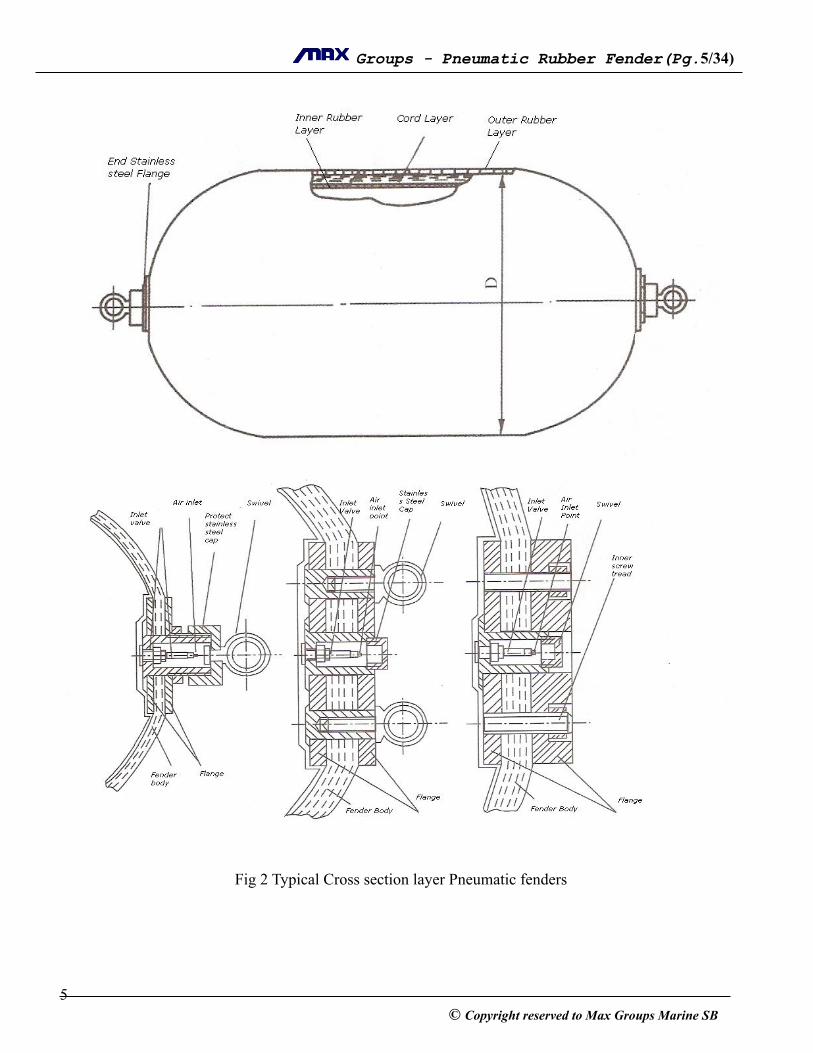
1. construction features !1.1 Basic body construction
The ! floating-type pneumatic rubber fenders are kind of a cylindrical air-bag with hemispherical
heads at both end. Basic body construction of this fender consists of an outer rubber layer, cord layers and
inner rubber layer. All of these are vulcanized together.
End flanges are at both end for convenience of air charge and other purposes.
Outer rubber layer
The outer rubber layer protects the cord layer and inner layer from abrasion and other external forces. This
compound has sufficient tensile and tear strength to withstand any weather condition and hard usage. ! 3
© Copyright reserved to Max Groups Marine SB
! Groups - Pneumatic Rubber Fender(Pg. ! /! ) 4 34
!Cord layers
The cord layers are arranged at ideal angles to hold the internal pressure and to distribute the stress evenly.
The! fenders cord layer is constructed by means of integrative twine technology and consists of
polyamide fiber with high tensile stress, so that the fenders have unique strength and uniformity in
different directions.
!Inner rubber layer
The inner rubber layer seals the air inside, utilizing a compound with airtight quality.
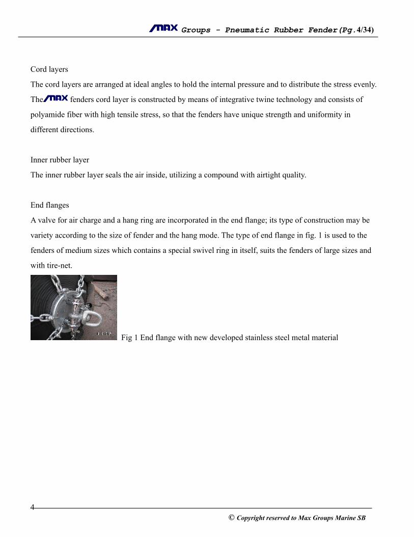
!End flanges
A valve for air charge and a hang ring are incorporated in the end flange; its type of construction may be
variety according to the size of fender and the hang mode. The type of end flange in fig. 1 is used to the
fenders of medium sizes which contains a special swivel ring in itself, suits the fenders of large sizes and
with tire-net.
! Fig 1 End flange with new developed stainless steel metal material
! 4© Copyright reserved to Max Groups Marine SB
! Groups - Pneumatic Rubber Fender(Pg. ! /! ) 5 34
!
!
!Fig 2 Typical Cross section layer Pneumatic fenders !!!!!
! 5© Copyright reserved to Max Groups Marine SB
! Groups - Pneumatic Rubber Fender(Pg. ! /! ) 6 34
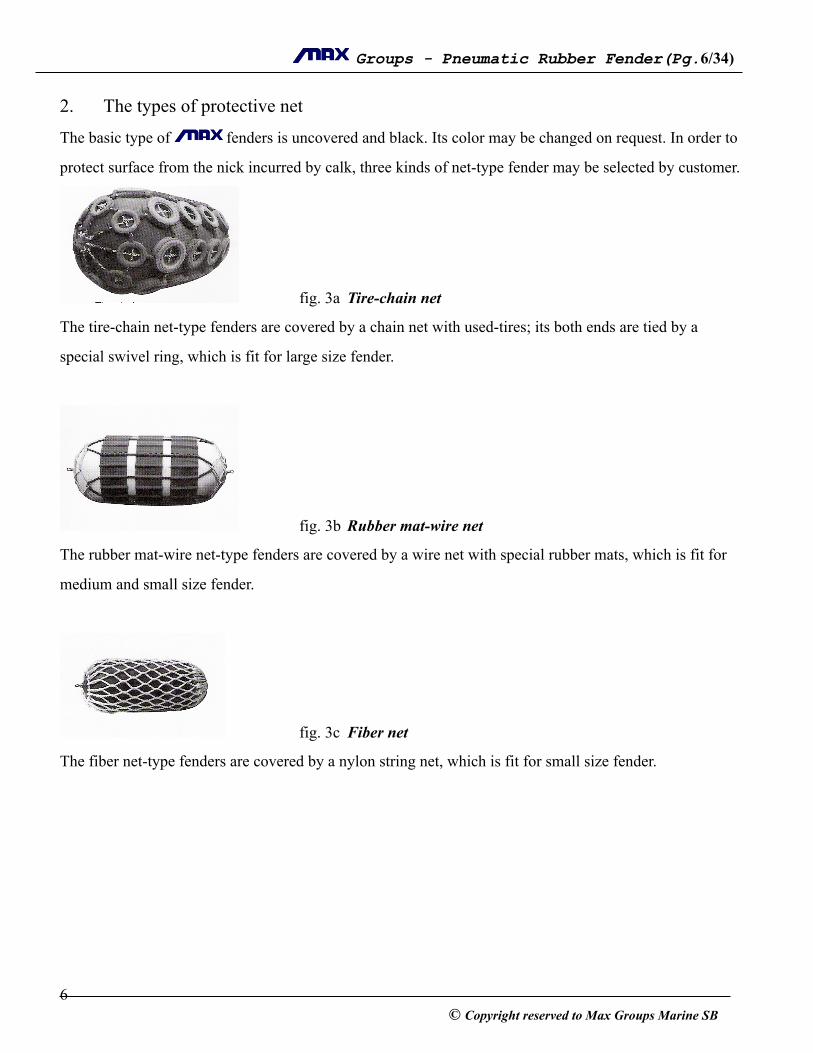
2. The types of protective net
The basic type of ! fenders is uncovered and black. Its color may be changed on request. In order to
protect surface from the nick incurred by calk, three kinds of net-type fender may be selected by customer.
! fig. 3a Tire-chain net
The tire-chain net-type fenders are covered by a chain net with used-tires; its both ends are tied by a
special swivel ring, which is fit for large size fender.
!
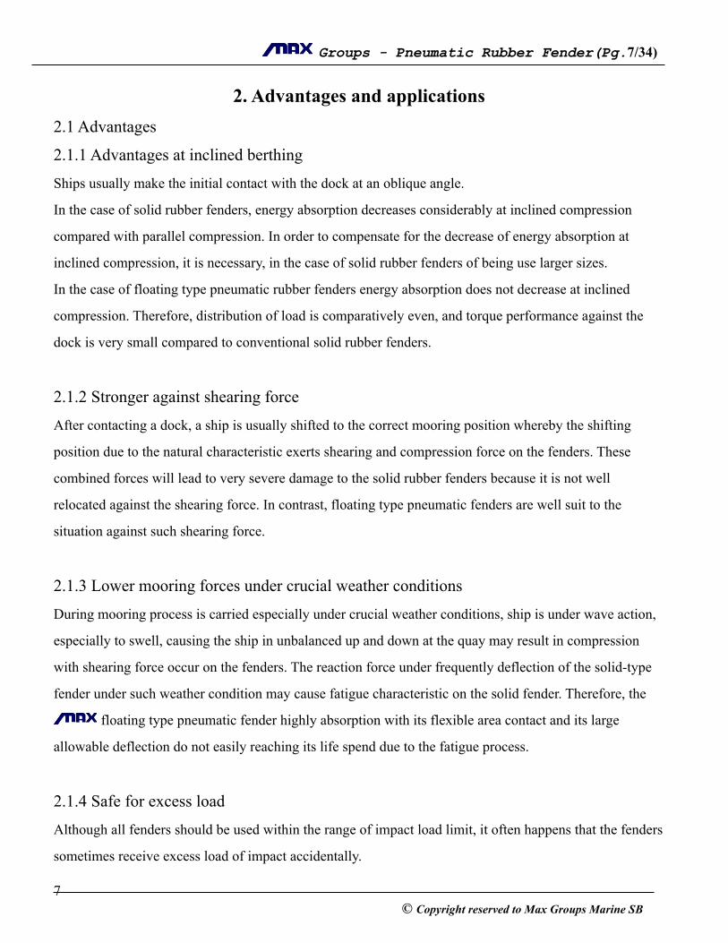
! fig. 3b Rubber mat-wire net
The rubber mat-wire net-type fenders are covered by a wire net with special rubber mats, which is fit for
medium and small size fender.
!
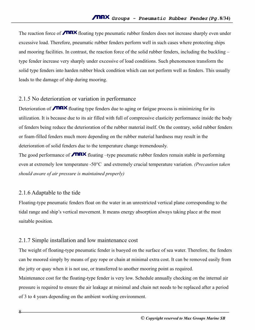
! fig. 3c Fiber net
The fiber net-type fenders are covered by a nylon string net, which is fit for small size fender.
!!!!!!
! 6© Copyright reserved to Max Groups Marine SB
! Groups - Pneumatic Rubber Fender(Pg. ! /! ) 7 34
2. Advantages and applications 2.1 Advantages
2.1.1 Advantages at inclined berthing
Ships usually make the initial contact with the dock at an oblique angle.
In the case of solid rubber fenders, energy absorption decreases considerably at inclined compression
compared with parallel compression. In order to compensate for the decrease of energy absorption at
inclined compression, it is necessary, in the case of solid rubber fenders of being use larger sizes.
In the case of floating type pneumatic rubber fenders energy absorption does not decrease at inclined
compression. Therefore, distribution of load is comparatively even, and torque performance against the
dock is very small compared to conventional solid rubber fenders.
!2.1.2 Stronger against shearing force
After contacting a dock, a ship is usually shifted to the correct mooring position whereby the shifting
position due to the natural characteristic exerts shearing and compression force on the fenders. These
combined forces will lead to very severe damage to the solid rubber fenders because it is not well
relocated against the shearing force. In contrast, floating type pneumatic fenders are well suit to the
situation against such shearing force.
!2.1.3 Lower mooring forces under crucial weather conditions
During mooring process is carried especially under crucial weather conditions, ship is under wave action,
especially to swell, causing the ship in unbalanced up and down at the quay may result in compression
with shearing force occur on the fenders. The reaction force under frequently deflection of the solid-type
fender under such weather condition may cause fatigue characteristic on the solid fender. Therefore, the
! floating type pneumatic fender highly absorption with its flexible area contact and its large
allowable deflection do not easily reaching its life spend due to the fatigue process.
!2.1.4 Safe for excess load
Although all fenders should be used within the range of impact load limit, it often happens that the fenders
sometimes receive excess load of impact accidentally.
! 7© Copyright reserved to Max Groups Marine SB
! Groups - Pneumatic Rubber Fender(Pg. ! /! ) 8 34
The reaction force of ! floating type pneumatic rubber fenders does not increase sharply even under
excessive load. Therefore, pneumatic rubber fenders perform well in such cases where protecting ships
and mooring facilities. In contrast, the reaction force of the solid rubber fenders, including the buckling –
type fender increase very sharply under excessive of load conditions. Such phenomenon transform the
solid type fenders into harden rubber block condition which can not perform well as fenders. This usually
leads to the damage of ship during mooring.
!2.1.5 No deterioration or variation in performance
Deterioration of ! floating type fenders due to aging or fatigue process is minimizing for its
utilization. It is because due to its air filled with full of compressive elasticity performance inside the body
of fenders being reduce the deterioration of the rubber material itself. On the contrary, solid rubber fenders
or foam-filled fenders much more depending on the rubber material hardness may result in the
deterioration of solid fenders due to the temperature change tremendously.
The good performance of ! floating –type pneumatic rubber fenders remain stable in performing
even at extremely low temperature -50°C and extremely crucial temperature variation. (Precaution taken
should aware of air pressure is maintained properly)
!2.1.6 Adaptable to the tide
Floating-type pneumatic fenders float on the water in an unrestricted vertical plane corresponding to the
tidal range and ship’s vertical movement. It means energy absorption always taking place at the most
suitable position.
!2.1.7 Simple installation and low maintenance cost
The weight of floating-type pneumatic fender is buoyed on the surface of sea water. Therefore, the fenders
can be moored simply by means of guy rope or chain at minimal extra cost. It can be removed easily from
the jetty or quay when it is not use, or transferred to another mooring point as required.
Maintenance cost for the floating-type fender is very low. Schedule annually checking on the internal air
pressure is required to ensure the air leakage at minimal and chain net needs to be replaced after a period
of 3 to 4 years depending on the ambient working environment.
! 8© Copyright reserved to Max Groups Marine SB
! Groups - Pneumatic Rubber Fender(Pg. ! /! ) 9 34
!!2. Application
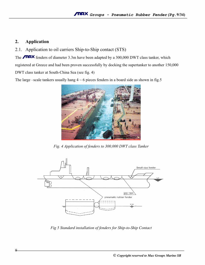
2.1. Application to oil carriers Ship-to-Ship contact (STS)
The ! fenders of diameter 3.3m have been adapted by a 300,000 DWT class tanker, which
registered at Greece and had been proven successfully by docking the supertanker to another 150,000
DWT class tanker at South-China Sea (see fig. 4)
The large –scale tankers usually hang 4 ~ 6 pieces fenders in a board side as shown in fig.5
!
Fig. 4 Application of fenders to 300,000 DWT class Tanker
!
!
Fig 5 Standard installation of fenders for Ship-to-Ship Contact
!! 9
© Copyright reserved to Max Groups Marine SB
! Groups - Pneumatic Rubber Fender(Pg. ! /! ) 10 34
In case of Ship-to-Ship contact, four pieces of large size fenders are usually floated on the sea water as
primary fender to absorb impact energy at berthing, two pieces of small size fenders are hung on the hull
at both bow and stern to prevent contact from rolling of ship due to swell.
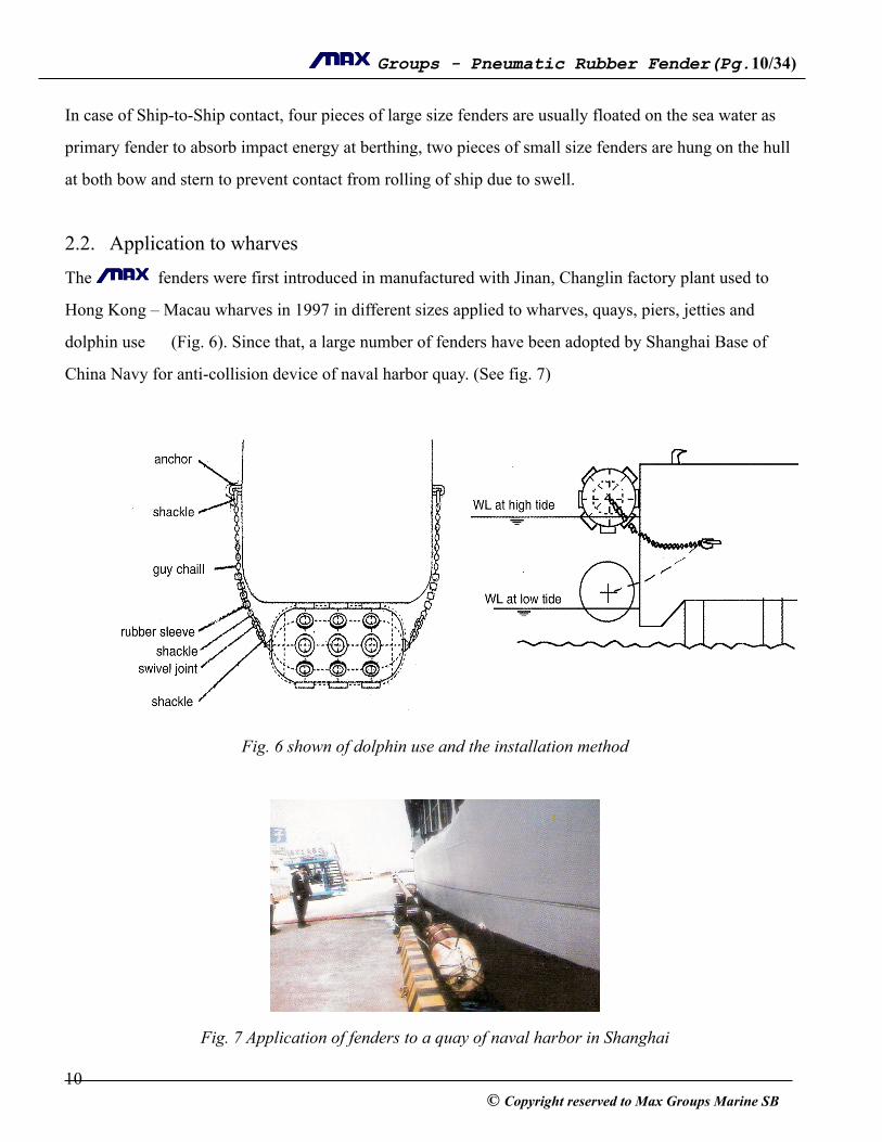
!2.2. Application to wharves
The ! fenders were first introduced in manufactured with Jinan, Changlin factory plant used to
Hong Kong – Macau wharves in 1997 in different sizes applied to wharves, quays, piers, jetties and
dolphin use (Fig. 6). Since that, a large number of fenders have been adopted by Shanghai Base of
China Navy for anti-collision device of naval harbor quay. (See fig. 7)
!
!
Fig. 6 shown of dolphin use and the installation method
!
!
Fig. 7 Application of fenders to a quay of naval harbor in Shanghai
! 10© Copyright reserved to Max Groups Marine SB

! Groups - Pneumatic Rubber Fender(Pg. ! /! ) 11 34
!!!!!
Table 1 indicate different sizes of installation parts
!3. Specification and Performances
1. Calculation of performance
It assumed that the fender is at initial stage of static pressure condition with its inner volume equal Vo and
its inner pressure Po. When the fenders is compressed up to x in the diameter direction, its inner volume
Fender size
(Diameter x
Length)
Guy wire
Diameter
(mm)
Guy chain or
Fiber rope
Diameter (mm)
Shackle
Diameter (mm)
Swivel joint
(mm)
Anchor
Diameter (mm)
0.5 x 1.0 12 14 14 18 18
0.6 x 1.0 12 14 14 18 20
0.7 x 1.5 14 16 18 18 25
1.0 x 1.5 14 16 18 18 25
1.0 x 2.0 14 16 18 18 25
1.2 x 2.0 16 16 18 22 28
1.35 x 3.0 16 18 18 22 28
1.5 x 3.0 18 18 22 24 28
1.7 x 3.0 20 20 24 24 30
2.0 x 3.5 24 24 28 28 34
2.5 x 4.0 24 26 28 32 34
2.5 x 5.5 24 26 28 34 34
3.3 x 4.5 26 28 30 38 40
3.3 x 6.5 28 30 32 44 60
! 11© Copyright reserved to Max Groups Marine SB
! Groups - Pneumatic Rubber Fender(Pg. ! /! ) 12 34
changes, Vx, inner pressure Px. with the area of contact surface Sx, then the reaction force Rx may be
calculated as follows:
Rx = Px . Sx
Therefore, the energy absoption Ex at the moment is :
x Ex = ∫ Rx dx
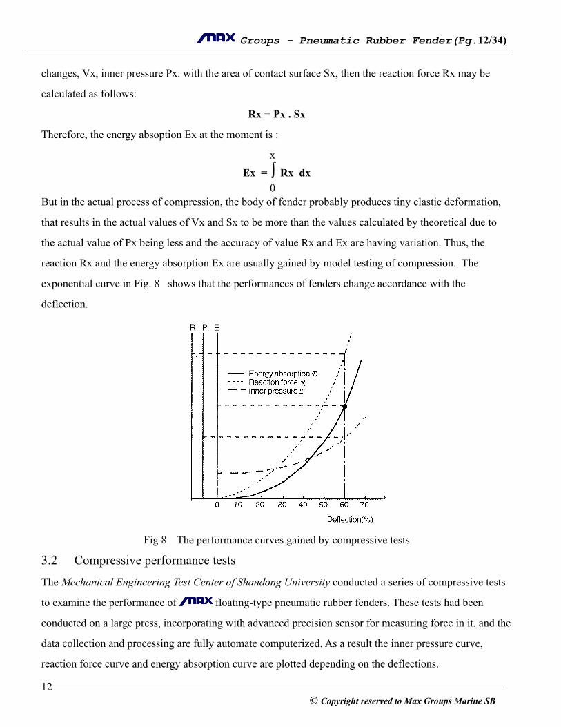
0 But in the actual process of compression, the body of fender probably produces tiny elastic deformation,
that results in the actual values of Vx and Sx to be more than the values calculated by theoretical due to
the actual value of Px being less and the accuracy of value Rx and Ex are having variation. Thus, the
reaction Rx and the energy absorption Ex are usually gained by model testing of compression. The
exponential curve in Fig. 8 shows that the performances of fenders change accordance with the
deflection.
!
Fig 8 The performance curves gained by compressive tests
3.2 Compressive performance tests
The Mechanical Engineering Test Center of Shandong University conducted a series of compressive tests
to examine the performance of ! floating-type pneumatic rubber fenders. These tests had been
conducted on a large press, incorporating with advanced precision sensor for measuring force in it, and the
data collection and processing are fully automate computerized. As a result the inner pressure curve,
reaction force curve and energy absorption curve are plotted depending on the deflections.
! 12© Copyright reserved to Max Groups Marine SB
! Groups - Pneumatic Rubber Fender(Pg. ! /! ) 13 34
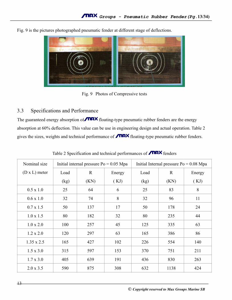
Fig. 9 is the pictures photographed pneumatic fender at different stage of deflections.
!
Fig. 9 Photos of Compressive tests
!3.3 Specifications and Performance
The guaranteed energy absorption of ! floating-type pneumatic rubber fenders are the energy
absorption at 60% deflection. This value can be use in engineering design and actual operation. Table 2
gives the sizes, weights and technical performance of ! floating-type pneumatic rubber fenders.
!Table 2 Specification and technical performances of ! fenders
Nominal size
(D x L) meter
Initial internal pressure Po = 0.05 Mpa Initial Internal pressure Po = 0.08 Mpa
Load
(kg)
R
(KN)
Energy
( KJ)
Load
(kg)
R
(KN)
Energy
( KJ)
0.5 x 1.0 25 64 6 25 83 8
0.6 x 1.0 32 74 8 32 96 11
0.7 x 1.5 50 137 17 50 178 24
1.0 x 1.5 80 182 32 80 235 44
1.0 x 2.0 100 257 45 125 335 63
1.2 x 2.0 120 297 63 165 386 86
1.35 x 2.5 165 427 102 226 554 140
1.5 x 3.0 315 597 153 370 751 211
1.7 x 3.0 405 639 191 436 830 263
2.0 x 3.5 590 875 308 632 1138 424
! 13© Copyright reserved to Max Groups Marine SB

! Groups - Pneumatic Rubber Fender(Pg. ! /! ) 14 34
Note :
• Energy represents s the Guarantee energy absorption at 60% deflection.
• The weight is fender’s body weight without protective net may vary ± 10%
• Reaction Force, R ± 10%; Deflection: ± 5% and each of the reaction force and energy absorption
are measured under static condition.
• Special Sizes of others dimension are available upon request.
!!!!!4.0 User selection
When selecting the size of fenders, it should be selected base on the consideration of kinetic energy of
contact between two vessels or between vessel and berthing facilities may be absorbed by a single fender.
The following tables are given for determining the energy absorption depends on approaching velocities
for various ships.
4.1 Energy absorption for ship-to-Jetty
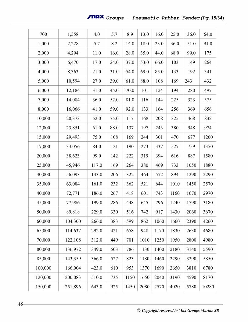
Table 3 Energy absorption of oil tankers at ¼ point berthing (kJ)
2.5 x 4.0 1050 1381 663 1110 1815 925
2.5 x 5.5 1333 2019 943 1410 2653 1317
3.0 x 5.0 1880 2104 1210 2155 2700 1571
3.0 x 6.0 2160 2583 1485 2470 3292 1888
3.3 x 4.5 2020 1884 1175 2300 2476 1640
3.3 x 6.0 2300 2783 1675 2600 3652 2338
3.3 x 6.5 2700 3015 1814 3080 3961 2532
DWT Assumed Weight(t)
Approaching velocity (m/s)
0.10 0.12 0.15 0.18 0.20 0.25 0.30 0.40
300 668 1.7 2.5 3.8 5.5 6.8 11.0 15.0 27.0
500 1,091 2.8 4.0 6.3 9.0 11.0 17.0 25.0 45.0
! 14© Copyright reserved to Max Groups Marine SB
! Groups - Pneumatic Rubber Fender(Pg. ! /! ) 15 34
700 1,558 4.0 5.7 8.9 13.0 16.0 25.0 36.0 64.0
1,000 2,228 5.7 8.2 14.0 18.0 23.0 36.0 51.0 91.0
2,000 4,294 11.0 16.0 28.0 35.0 44.0 68.0 99.0 175
3,000 6,470 17.0 24.0 37.0 53.0 66.0 103 149 264
4,000 8,363 21.0 31.0 54.0 69.0 85.0 133 192 341
5,000 10,594 27.0 39.0 61.0 88.0 108 169 243 432
6,000 12,184 31.0 45.0 70.0 101 124 194 280 497
7,000 14,084 36.0 52.0 81.0 116 144 225 323 575
8,000 16,066 41.0 59.0 92.0 133 164 256 369 656
10,000 20,373 52.0 75.0 117 168 208 325 468 832
12,000 23,851 61.0 88.0 137 197 243 380 548 974
15,000 29,493 75.0 108 169 244 301 470 677 1200
17,000 33,056 84.0 121 190 273 337 527 759 1350
20,000 38,623 99.0 142 222 319 394 616 887 1580
25,000 45,946 117.0 169 264 380 469 733 1050 1880
30,000 56,093 143.0 206 322 464 572 894 1290 2290
35,000 63,084 161.0 232 362 521 644 1010 1450 2570
40,000 72,771 186.0 267 418 601 743 1160 1670 2970
45,000 77,986 199.0 286 448 645 796 1240 1790 3180
50,000 89,818 229.0 330 516 742 917 1430 2060 3670
60,000 104,300 266.0 383 599 862 1060 1660 2390 4260
65,000 114,637 292.0 421 658 948 1170 1830 2630 4680
70,000 122,108 312.0 449 701 1010 1250 1950 2800 4980
80,000 136,972 349.0 503 786 1130 1400 2180 3140 5590
85,000 143,359 366.0 527 823 1180 1460 2290 3290 5850
100,000 166,004 423.0 610 953 1370 1690 2650 3810 6780
120,000 200,083 510.0 735 1150 1650 2040 3190 4590 8170
150,000 251,896 643.0 925 1450 2080 2570 4020 5780 10280
! 15© Copyright reserved to Max Groups Marine SB
! Groups - Pneumatic Rubber Fender(Pg. ! /! ) 16 34
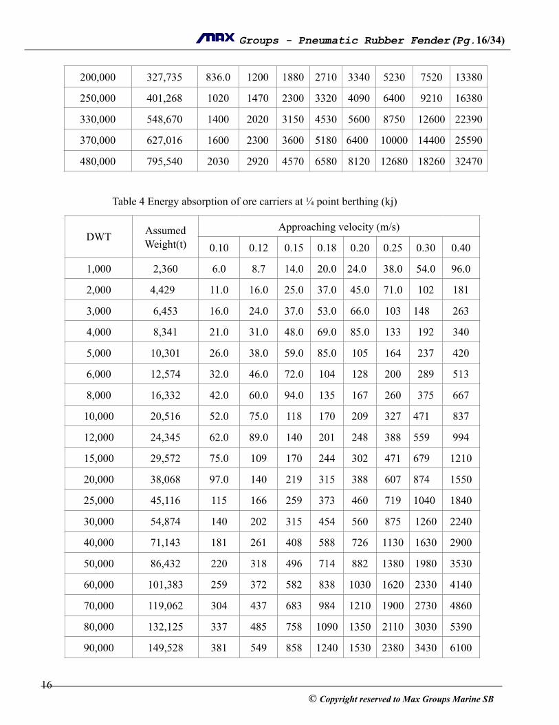
! Table 4 Energy absorption of ore carriers at ¼ point berthing (kj)
200,000 327,735 836.0 1200 1880 2710 3340 5230 7520 13380
250,000 401,268 1020 1470 2300 3320 4090 6400 9210 16380
330,000 548,670 1400 2020 3150 4530 5600 8750 12600 22390
370,000 627,016 1600 2300 3600 5180 6400 10000 14400 25590
480,000 795,540 2030 2920 4570 6580 8120 12680 18260 32470
DWT Assumed Weight(t)
Approaching velocity (m/s)
0.10 0.12 0.15 0.18 0.20 0.25 0.30 0.40
1,000 2,360 6.0 8.7 14.0 20.0 24.0 38.0 54.0 96.0
2,000 4,429 11.0 16.0 25.0 37.0 45.0 71.0 102 181
3,000 6,453 16.0 24.0 37.0 53.0 66.0 103 148 263
4,000 8,341 21.0 31.0 48.0 69.0 85.0 133 192 340
5,000 10,301 26.0 38.0 59.0 85.0 105 164 237 420
6,000 12,574 32.0 46.0 72.0 104 128 200 289 513
8,000 16,332 42.0 60.0 94.0 135 167 260 375 667
10,000 20,516 52.0 75.0 118 170 209 327 471 837
12,000 24,345 62.0 89.0 140 201 248 388 559 994
15,000 29,572 75.0 109 170 244 302 471 679 1210
20,000 38,068 97.0 140 219 315 388 607 874 1550
25,000 45,116 115 166 259 373 460 719 1040 1840
30,000 54,874 140 202 315 454 560 875 1260 2240
40,000 71,143 181 261 408 588 726 1130 1630 2900
50,000 86,432 220 318 496 714 882 1380 1980 3530
60,000 101,383 259 372 582 838 1030 1620 2330 4140
70,000 119,062 304 437 683 984 1210 1900 2730 4860
80,000 132,125 337 485 758 1090 1350 2110 3030 5390
90,000 149,528 381 549 858 1240 1530 2380 3430 6100
! 16© Copyright reserved to Max Groups Marine SB
! Groups - Pneumatic Rubber Fender(Pg. ! /! ) 17 34
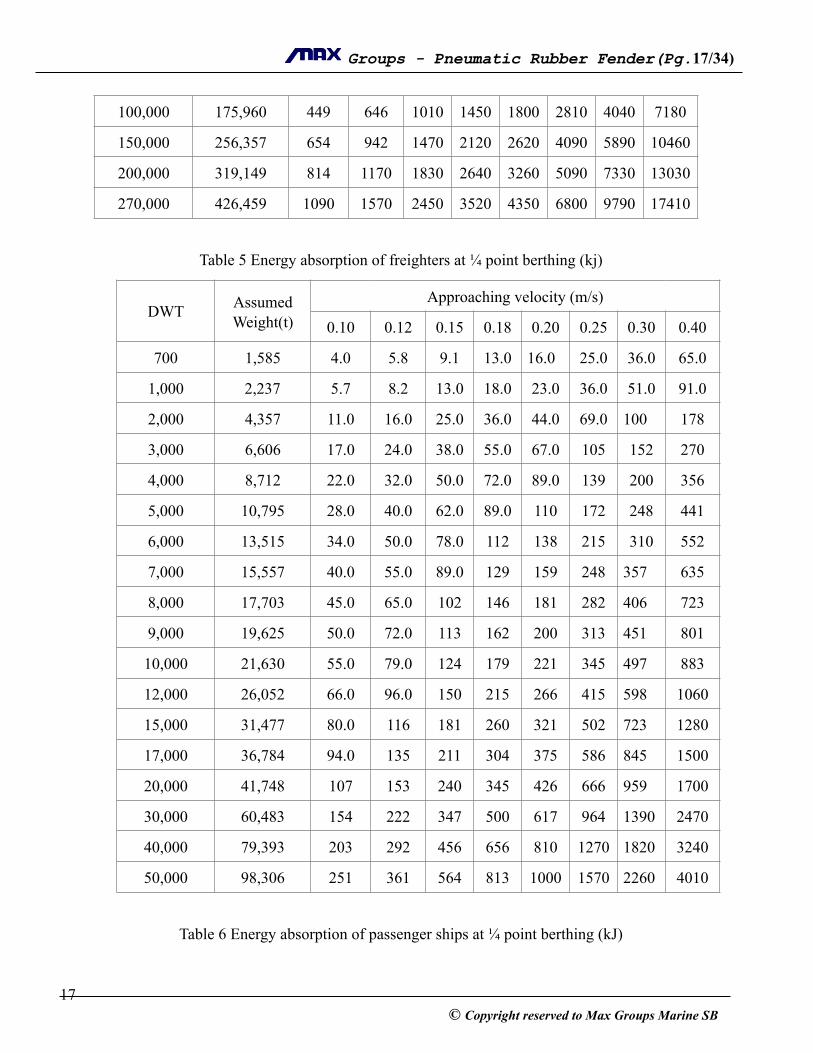
!Table 5 Energy absorption of freighters at ¼ point berthing (kj)
!Table 6 Energy absorption of passenger ships at ¼ point berthing (kJ)
100,000 175,960 449 646 1010 1450 1800 2810 4040 7180
150,000 256,357 654 942 1470 2120 2620 4090 5890 10460
200,000 319,149 814 1170 1830 2640 3260 5090 7330 13030
270,000 426,459 1090 1570 2450 3520 4350 6800 9790 17410
DWT Assumed Weight(t)
Approaching velocity (m/s)
0.10 0.12 0.15 0.18 0.20 0.25 0.30 0.40
700 1,585 4.0 5.8 9.1 13.0 16.0 25.0 36.0 65.0
1,000 2,237 5.7 8.2 13.0 18.0 23.0 36.0 51.0 91.0
2,000 4,357 11.0 16.0 25.0 36.0 44.0 69.0 100 178
3,000 6,606 17.0 24.0 38.0 55.0 67.0 105 152 270
4,000 8,712 22.0 32.0 50.0 72.0 89.0 139 200 356
5,000 10,795 28.0 40.0 62.0 89.0 110 172 248 441
6,000 13,515 34.0 50.0 78.0 112 138 215 310 552
7,000 15,557 40.0 55.0 89.0 129 159 248 357 635
8,000 17,703 45.0 65.0 102 146 181 282 406 723
9,000 19,625 50.0 72.0 113 162 200 313 451 801
10,000 21,630 55.0 79.0 124 179 221 345 497 883
12,000 26,052 66.0 96.0 150 215 266 415 598 1060
15,000 31,477 80.0 116 181 260 321 502 723 1280
17,000 36,784 94.0 135 211 304 375 586 845 1500
20,000 41,748 107 153 240 345 426 666 959 1700
30,000 60,483 154 222 347 500 617 964 1390 2470
40,000 79,393 203 292 456 656 810 1270 1820 3240
50,000 98,306 251 361 564 813 1000 1570 2260 4010
! 17© Copyright reserved to Max Groups Marine SB

! Groups - Pneumatic Rubber Fender(Pg. ! /! ) 18 34
!!Table 7 Energy absorption of barges or lighters at ¼ point berthing (kJ)
!!
DWT Assumed Weight(t)
Approaching velocity (m/s)
0.10 0.12 0.15 0.18 0.20 0.25 0.30 0.40
500 845 2.2 3.1 4.9 7.0 8.6 13.0 19.0 34.0
1,000 1,709 4.3 6.2 9.8 14.0 17.0 27.0 39.0 70.0
2,000 3,500 8.9 13.0 20.0 29.0 36.0 56.0 80.0 143
3,000 5,282 13.0 19.0 30.0 44.0 54.0 84.0 121 216
4,000 7,105 18.0 26.0 41.0 59.0 73.0 113 163 290
5,000 8,912 23.0 33.0 51.0 74.0 91.0 142 205 364
6,000 12,083 31.0 44.0 69.0 100 123 193 277 493
7,000 13,873 35.0 51.0 80.0 115 142 221 319 566
8,000 15,346 39.0 56.0 88.0 127 157 245 352 626
9,000 16,986 43.0 62.0 97.0 140 173 271 390 693
10,000 18,661 48.0 69.0 107 154 190 298 428 762
15,000 26,283 67.0 97.0 151 217 268 419 603 1070
20,000 33,423 85.0 123 192 276 341 533 767 1360
30,000 47,952 122 176 275 396 489 765 1100 1960
50,000 71,744 183 264 412 593 732 1140 1650 2930
80,000 111,956 286 411 643 925 1140 1790 2570 4570
G/T Assuming Weight ( t )
Approaching velocity ( m/s )
0.20 0.25 0.30 0.35 0.40 0.50 0.60
50 85 0.9 1.4 2.0 2.7 3.5 5.4 7.8
100 161 1.6 2.6 3.7 5.0 6.6 11.0 15.0
150 241 2.5 3.8 5.5 7.5 9.8 15.0 22.0
200 319 3.3 5.1 7.3 10.0 13/0 20.0 29.0
300 496 5.1 7.9 11.0 15.0 20.0 32.0 46.0
! 18© Copyright reserved to Max Groups Marine SB
! Groups - Pneumatic Rubber Fender(Pg. ! /! ) 19 34
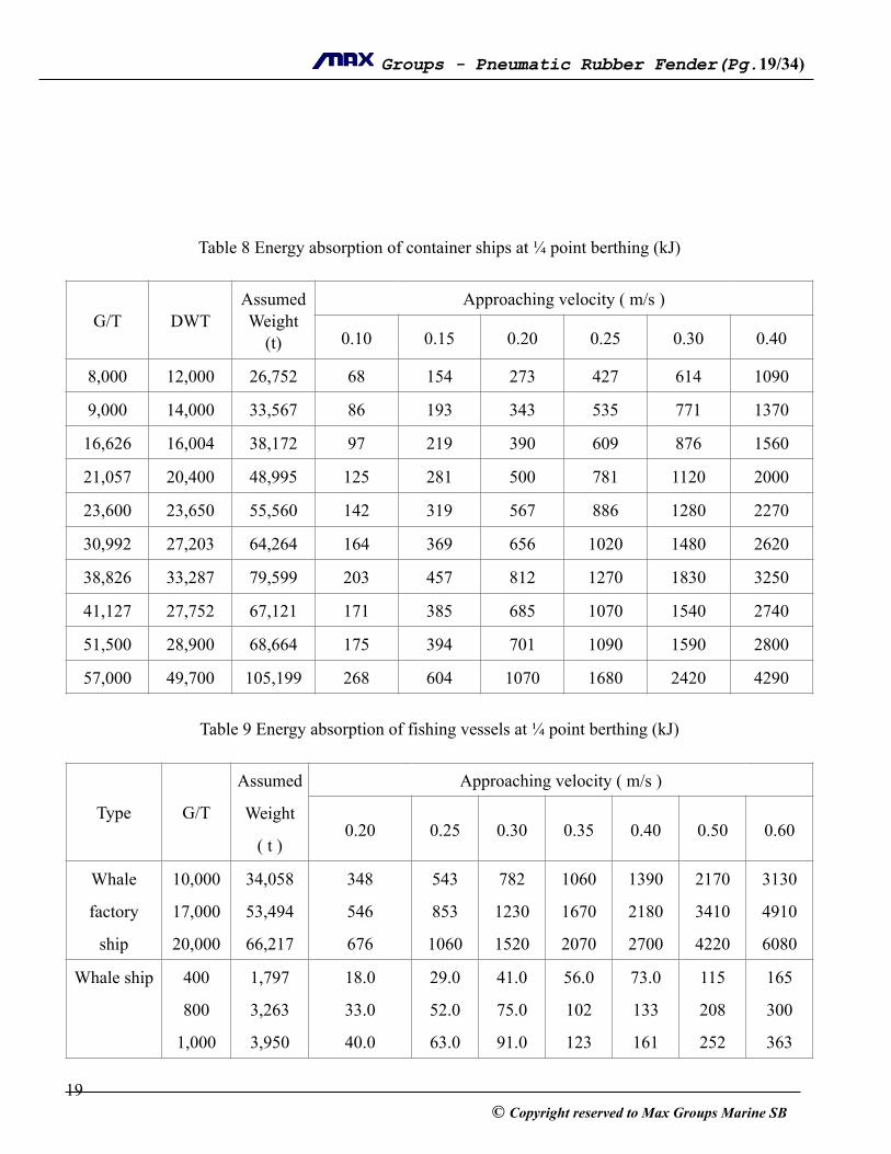
!!!!!!Table 8 Energy absorption of container ships at ¼ point berthing (kJ) !
!Table 9 Energy absorption of fishing vessels at ¼ point berthing (kJ) !
G/T DWTAssumed Weight
(t)
Approaching velocity ( m/s )
0.10 0.15 0.20 0.25 0.30 0.40
8,000 12,000 26,752 68 154 273 427 614 1090
9,000 14,000 33,567 86 193 343 535 771 1370
16,626 16,004 38,172 97 219 390 609 876 1560
21,057 20,400 48,995 125 281 500 781 1120 2000
23,600 23,650 55,560 142 319 567 886 1280 2270
30,992 27,203 64,264 164 369 656 1020 1480 2620
38,826 33,287 79,599 203 457 812 1270 1830 3250
41,127 27,752 67,121 171 385 685 1070 1540 2740
51,500 28,900 68,664 175 394 701 1090 1590 2800
57,000 49,700 105,199 268 604 1070 1680 2420 4290
Type G/T
Assumed
Weight
( t )
Approaching velocity ( m/s )
0.20 0.25 0.30 0.35 0.40 0.50 0.60
Whale
factory
ship
10,000
17,000
20,000
34,058
53,494
66,217
348
546
676
543
853
1060
782
1230
1520
1060
1670
2070
1390
2180
2700
2170
3410
4220
3130
4910
6080
Whale ship 400
800
1,000
1,797
3,263
3,950
18.0
33.0
40.0
29.0
52.0
63.0
41.0
75.0
91.0
56.0
102
123
73.0
133
161
115
208
252
165
300
363
! 19© Copyright reserved to Max Groups Marine SB

! Groups - Pneumatic Rubber Fender(Pg. ! /! ) 20 34
! !Table 10 Energy absorption of ferry boats at ¼ point berthing (KJ)
Trawler
Vessel
400
800
1,000
2,000
3,000
2,297
3,693
4,458
7,173
9,863
23.0
38.0
45.0
73.0
101
37.0
59.0
71.0
114
157
53.0
85.0
102
165
226
72.0
115
139
224
308
94.0
151
182
293
403
146
236
284
457
629
211
339
409
659
906
Skipjack
vessel
20
50
100
200
126
202
390
779
1.3
2.1
4.0
7.9
2.0
3.2
6.2
12.0
2.9
4.6
9.0
18.0
3.9
6.3
12.0
24.0
5.1
8.2
16.0
32.0
8.0
12.9
25.0
50.0
12.0
19.0
36.0
72.0
Mackerel
vessel
20
50
100
112
266
525
1.1
2.7
5.4
1.8
4.2
8.4
2.6
6.1
12.0
3.5
8.3
16.0
4.6
11.0
21.0
7.1
17.0
33.0
10.0
24.0
48.0
Tuna
long-liner
150
200
400
590
780
1,681
6.0
8.0
17.0
9.4
12.0
27.0
14.0
18.0
39.0
18.0
24.0
53.0
24.0
32.0
69.0
38.0
50.0
107
54.0
72.0
154
Round
Haul netter
20
50
100
75
191
377
0.8
1.9
3.8
1.1
3.0
6.0
1.7
4.4
8.7
2.3
6.0
12.0
3.1
7.8
15.0
4.8
12.0
24.0
6.9
18.0
35.0
Towing
net vessel
20
50
100
300
500
99
204
361
1,138
1,838
1.0
2.1
3.7
12.0
19.0
1.6
3.3
5.8
18.0
29.0
2.3
4.7
8.3
26.0
42.0
3.1
6.4
11.0
36.0
57.0
4.0
8.3
15.0
46.0
75.0
6.3
13.0
23.0
73.0
117
9.1
19.0
33.0
105
169
General
fishing
vessel
20
50
100
150
77
195
350
500
0.8
2.0
3.6
5.1
1.2
3.1
5.6
8.0
1.8
4.5
8.0
11.0
2.4
6.1
11.0
16.0
3.1
8.0
14.0
20.0
4.9
12.0
22.0
32.0
7.1
18.0
32.0
46.0
! 20© Copyright reserved to Max Groups Marine SB
! Groups - Pneumatic Rubber Fender(Pg. ! /! ) 21 34
!
!>>>>>>>>>>>>>>>>>>>>>>>>>>>>>>>>>>>>>>>>>>>>>>>>> !
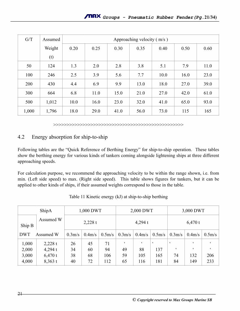
4.2 Energy absorption for ship-to-ship !Following tables are the “Quick Reference of Berthing Energy” for ship-to-ship operation. These tables show the berthing energy for various kinds of tankers coming alongside lightening ships at three different approaching speeds. !For calculation purpose, we recommend the approaching velocity to be within the range shown, i.e. from min. (Left side speed) to max. (Right side speed). This table shows figures for tankers, but it can be applied to other kinds of ships, if their assumed weights correspond to those in the table. !
Table 11 Kinetic energy (kJ) at ship-to-ship berthing !
G/T Assumed
Weight
(t)
Approaching velocity ( m/s )
0.20 0.25 0.30 0.35 0.40 0.50 0.60
50 124 1.3 2.0 2.8 3.8 5.1 7.9 11.0
100 246 2.5 3.9 5.6 7.7 10.0 16.0 23.0
200 430 4.4 6.9 9.9 13.0 18.0 27.0 39.0
300 664 6.8 11.0 15.0 21.0 27.0 42.0 61.0
500 1,012 10.0 16.0 23.0 32.0 41.0 65.0 93.0
1,000 1,796 18.0 29.0 41.0 56.0 73.0 115 165
ShipA 1,000 DWT 2,000 DWT 3,000 DWT
!Ship B
Assumed W 2,228 t 4,294 t 6,470 t
DWT Assumed W 0.3m/s 0.4m/s 0.5m/s 0.3m/s 0.4m/s 0.5m/s 0.3m/s 0.4m/s 0.5m/s
1,000 2,000 3,000 4,000
2,228 t 4,294 t 6,470 t 8,363 t
26 34 38 40
45 60 68 72
71 94 106 112
‘ 49 59 65
‘ 88 105 116
‘ 137 165 181
‘ ‘
74 84
‘ ‘
132 149
‘ ‘
206 233
! 21© Copyright reserved to Max Groups Marine SB
! Groups - Pneumatic Rubber Fender(Pg. ! /! ) 22 34
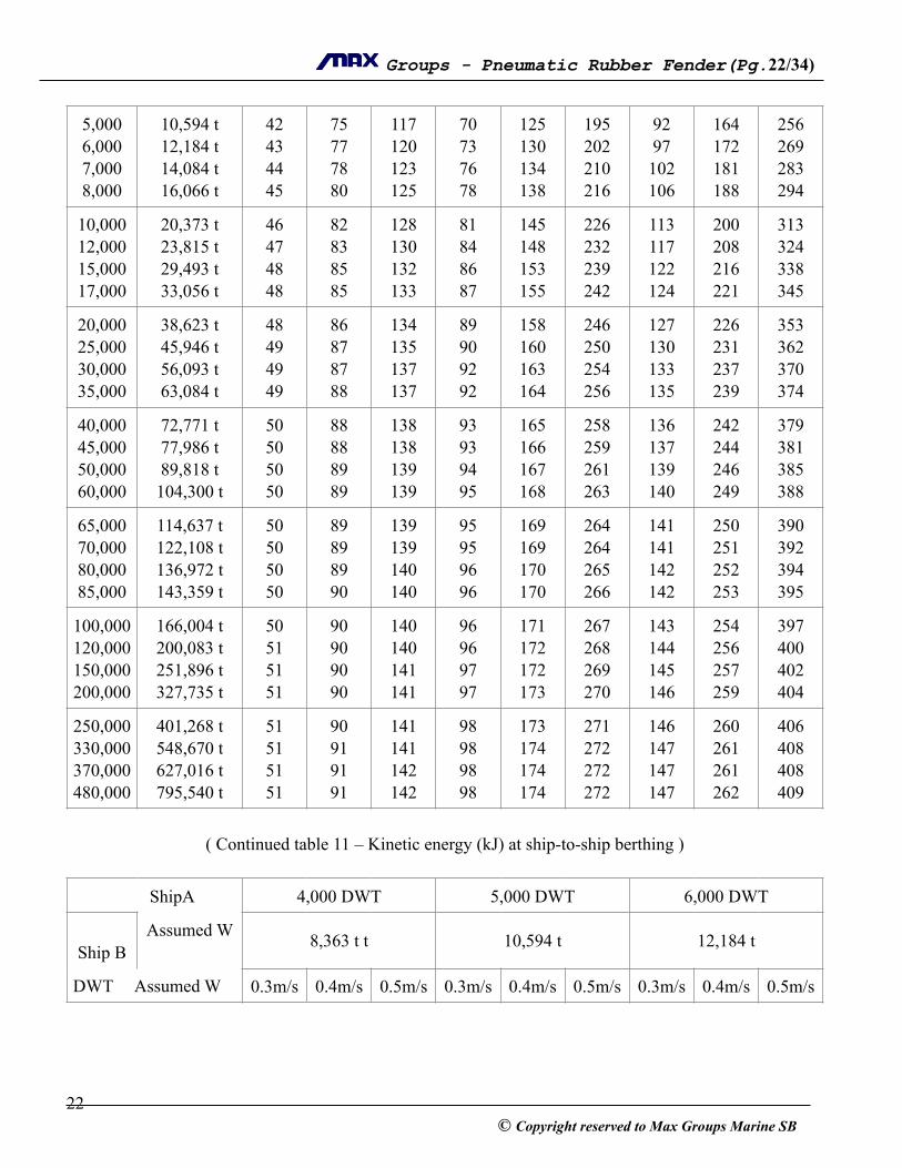
!( Continued table 11 – Kinetic energy (kJ) at ship-to-ship berthing ) !
5,000 6,000 7,000 8,000
10,594 t 12,184 t 14,084 t 16,066 t
42 43 44 45
75 77 78 80
117 120 123 125
70 73 76 78
125 130 134 138
195 202 210 216
92 97 102 106
164 172 181 188
256 269 283 294
10,000 12,000 15,000 17,000
20,373 t 23,815 t 29,493 t 33,056 t
46 47 48 48
82 83 85 85
128 130 132 133
81 84 86 87
145 148 153 155
226 232 239 242
113 117 122 124
200 208 216 221
313 324 338 345
20,000 25,000 30,000 35,000
38,623 t 45,946 t 56,093 t 63,084 t
48 49 49 49
86 87 87 88
134 135 137 137
89 90 92 92
158 160 163 164
246 250 254 256
127 130 133 135
226 231 237 239
353 362 370 374
40,000 45,000 50,000 60,000
72,771 t 77,986 t 89,818 t 104,300 t
50 50 50 50
88 88 89 89
138 138 139 139
93 93 94 95
165 166 167 168
258 259 261 263
136 137 139 140
242 244 246 249
379 381 385 388
65,000 70,000 80,000 85,000
114,637 t 122,108 t 136,972 t 143,359 t
50 50 50 50
89 89 89 90
139 139 140 140
95 95 96 96
169 169 170 170
264 264 265 266
141 141 142 142
250 251 252 253
390 392 394 395
100,000 120,000 150,000 200,000
166,004 t 200,083 t 251,896 t 327,735 t
50 51 51 51
90 90 90 90
140 140 141 141
96 96 97 97
171 172 172 173
267 268 269 270
143 144 145 146
254 256 257 259
397 400 402 404
250,000 330,000 370,000 480,000
401,268 t 548,670 t 627,016 t 795,540 t
51 51 51 51
90 91 91 91
141 141 142 142
98 98 98 98
173 174 174 174
271 272 272 272
146 147 147 147
260 261 261 262
406 408 408 409
ShipA 4,000 DWT 5,000 DWT 6,000 DWT
!Ship B
Assumed W 8,363 t t 10,594 t 12,184 t
DWT Assumed W 0.3m/s 0.4m/s 0.5m/s 0.3m/s 0.4m/s 0.5m/s 0.3m/s 0.4m/s 0.5m/s
! 22© Copyright reserved to Max Groups Marine SB
! Groups - Pneumatic Rubber Fender(Pg. ! /! ) 23 34
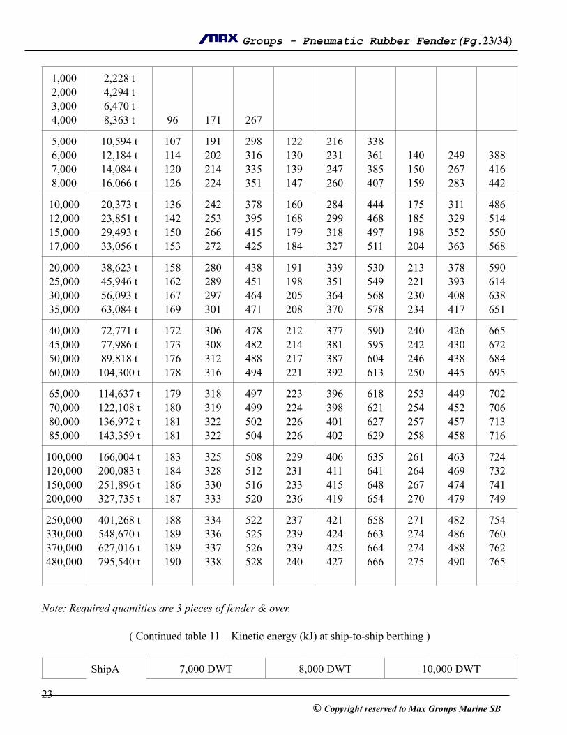
!Note: Required quantities are 3 pieces of fender & over. !
( Continued table 11 – Kinetic energy (kJ) at ship-to-ship berthing ) !
1,000 2,000 3,000 4,000
2,228 t 4,294 t 6,470 t 8,363 t
!!!96
!!!171
!!!267
5,000 6,000 7,000 8,000
10,594 t 12,184 t 14,084 t 16,066 t
107 114 120 126
191 202 214 224
298 316 335 351
122 130 139 147
216 231 247 260
338 361 385 407
!140 150 159
!249 267 283
!388 416 442
10,000 12,000 15,000 17,000
20,373 t 23,851 t 29,493 t 33,056 t
136 142 150 153
242 253 266 272
378 395 415 425
160 168 179 184
284 299 318 327
444 468 497 511
175 185 198 204
311 329 352 363
486 514 550 568
20,000 25,000 30,000 35,000
38,623 t 45,946 t 56,093 t 63,084 t
158 162 167 169
280 289 297 301
438 451 464 471
191 198 205 208
339 351 364 370
530 549 568 578
213 221 230 234
378 393 408 417
590 614 638 651
40,000 45,000 50,000 60,000
72,771 t 77,986 t 89,818 t 104,300 t
172 173 176 178
306 308 312 316
478 482 488 494
212 214 217 221
377 381 387 392
590 595 604 613
240 242 246 250
426 430 438 445
665 672 684 695
65,000 70,000 80,000 85,000
114,637 t 122,108 t 136,972 t 143,359 t
179 180 181 181
318 319 322 322
497 499 502 504
223 224 226 226
396 398 401 402
618 621 627 629
253 254 257 258
449 452 457 458
702 706 713 716
100,000 120,000 150,000 200,000
166,004 t 200,083 t 251,896 t 327,735 t
183 184 186 187
325 328 330 333
508 512 516 520
229 231 233 236
406 411 415 419
635 641 648 654
261 264 267 270
463 469 474 479
724 732 741 749
250,000 330,000 370,000 480,000
401,268 t 548,670 t 627,016 t 795,540 t
188 189 189 190
334 336 337 338
522 525 526 528
237 239 239 240
421 424 425 427
658 663 664 666
271 274 274 275
482 486 488 490
754 760 762 765
ShipA 7,000 DWT 8,000 DWT 10,000 DWT
! 23© Copyright reserved to Max Groups Marine SB

! Groups - Pneumatic Rubber Fender(Pg. ! /! ) 24 34
!Note: Required quantities are 3 pieces of fender & over. !
( Continued table 11 – Kinetic energy (kJ) at ship-to-ship berthing ) !
!Ship B
Assumed W 14,084 t 16,066 t 20,373 t
DWT Assumed W 0.3m/s 0.4m/s 0.5m/s 0.3m/s 0.4m/s 0.5m/s 0.25m/s 0.325m/s
0.4m/s
5,000 6,000 7,000 8,000
10,594 t 12,184 t 14,084 t 16,066 t
!!162 172
!!287 306
!!449 478
!!!184
!!!328
!!!512
10,000 12,000 15,000 17,000
20,373 t 23,851 t 29,493 t 33,056 t
191 203 219 227
340 361 389 403
531 565 608 630
206 220 239 248
366 392 424 441
573 612 663 689
162 175 192 201
274 296 325 339
416 448 492 514
20,000 25,000 30,000 35,000
38,623 t 45,946 t 56,093 t 63,084 t
237 247 258 264
421 440 459 470
358 687 718 734
260 273 287 294
463 486 510 522
723 759 796 816
213 225 238 245
359 380 403 415
544 576 610 628
40,000 45,000 50,000 60,000
72,771 t 77,986 t 89,818 t 104,300 t
271 274 279 285
481 487 497 506
752 761 776 791
302 306 313 320
537 544 556 568
839 849 869 888
254 257 265 272
429 435 447 459
649 659 678 695
65,000 70,000 80,000 85,000
114,637 t 122,108 t 136,972 t 143,359 t
288 290 293 294
512 515 521 523
800 805 814 818
323 326 330 332
575 579 587 589
898 905 917 921
276 278 283 284
446 470 478 480
706 712 724 728
100,000 120,000 150,000 200,000
166,004 t 200,083 t 251,896 t 327,735 t
298 302 306 310
530 537 544 551
828 839 850 861
336 341 347 351
598 607 616 625
934 948 963 976
289 295 300 306
489 498 508 517
740 754 769 783
250,000 330,000 370,000 480,000
401,268 t 548,670 t 627,016 t 795,540 t
312 315 316 318
555 560 562 565
867 875 878 882
355 358 360 361
630 637 639 643
985 995 999 1004
309 313 314 317
552 529 531 535
791 801 805 810
ShipA 12,000 DWT 15,000 DWT 17,000 DWT
! 24© Copyright reserved to Max Groups Marine SB

! Groups - Pneumatic Rubber Fender(Pg. ! /! ) 25 34
!Ship B
Assumed W 23,851 t 29,493 t 33,056 t
DWT Assumed W
0.25m/s
0.325m/s
0.4m/s
0.25m/s
0.325m/s
0.4m/s
0.25m/s
0.325m/s
0.4m/s
10,000 12,000 15,000 17,000
20,373 t 23,851 t 29,493 t 33,056 t
!190 210 221
!321 355 373
!487 538 565
!!235 248
!!397 420
!!602 636
!!!263
!!!445
!!!674
20,000 25,000 30,000 35,000
38,623 t 45,946 t 56,093 t 63,084 t
235 250 267 276
397 423 451 466
602 641 683 706
267 286 308 320
450 484 521 541
682 733 789 820
284 306 331 346
480 518 560 584
727 784 849 885
40,000 45,000 50,000 60,000
72,771 t 77,986 t 89,818 t 104,300 t
286 291 300 309
484 492 508 523
733 745 769 792
334 341 354 366
565 576 598 619
856 873 906 938
362 370 385 400
612 625 651 676
927 947 986 1024
65,000 70,000 80,000 85,000
114,637 t 122,108 t 136,972 t 143,359 t
315 318 324 326
532 537 547 551
806 814 829 834
374 379 387 390
632 640 654 659
957 969 990 998
409 415 424 428
691 701 717 724
1047 1061 1086 1096
100,000
120,000
150,000
200,000
166,004 t 200,083 t 251,896 t 327,735 t
332 340 347 354
562 574 587 599
851 869 889 907
339 410 421 431
675 692 711 729
1022 1049 1077 1104
439 452 466 479
742 764 787 809
1125 1157 1192 1225
250,000
330,000
370,000
480,000
401,268 t 548,670 t 627,016 t 795,540 t
359 364 366 369
606 616 619 624
919 933 937 945
435 446 449 453
740 754 759 766
1121 1142 1149 1160
487 497 500 506
823 840 846 855
1246 1272 1281 1295
ShipA 20,000 DWT 25,000 DWT 30,000 DWT
!Ship B
Assumed W 38,623 t 45,946 t 56,093 t
! 25© Copyright reserved to Max Groups Marine SB

! Groups - Pneumatic Rubber Fender(Pg. ! /! ) 26 34
!!(Continued table 11 – Kinetic energy (kJ) at ship-to-ship berthing ) !
DWT Assumed W
0.25m/s
0.325m/s
0.4m/s
0.25m/s
0.325m/s
0.4m/s
0.25m/s
0.325m/s
0.4m/s
20,000 25,000 30,000 35,000
38,623 t 45,946 t 56,093 t 63,084 t
308 334 365 382
520 565 616 645
788 856 933 977
!366 403 424
!619 680 716
!937 1031 1085
!!447 473
!!755 800
!!1144 1212
40,000 45,000 50,000 60,000
72,771 t 77,986 t 89,818 t 104,300 t
402 412 430 449
680 696 727 759
1029 1054 1102 1150
449 461 484 508
759 779 819 859
1149 1180 1240 1301
505 520 550 581
853 879 930 982
1292 1331 1409 1488
65,000 70,000 80,000 85,000
114,637 t 122,108 t 136,972 t 143,359 t
460 468 480 485
778 790 811 820
1179 1197 1229 1241
523 532 548 555
883 899 927 937
1338 1362 1404 1420
600 613 634 643
1014 1035 1072 1086
1537 1568 1624 1645
100,000
120,000
150,000
200,000
166,004 t 200,083 t 251,896 t 327,735 t
499 516 534 551
844 872 902 931
1278 1321 1366 1410
574 596 619 642
969 1006 1047 1085
1468 1552 1585 1644
668 698 731 763
1129 1180 1236 1290
1711 1787 1872 1954
250,000
330,000
370,000
480,000
401,268 t 548,670 t 627,016 t 795,540 t
562 575 580 587
949 972 980 992
1437 1472 1484 1503
657 676 682 692
1110 1142 1153 1170
1682 1730 1747 1772
784 811 821 835
1326 1371 1387 1411
2008 2076 2101 2138
ShipA 35,000 DWT 40,000 DWT 45,000 DWT
!Ship B
Assumed W 63,084 t 72,771 t 77,986 t
! 26© Copyright reserved to Max Groups Marine SB
! Groups - Pneumatic Rubber Fender(Pg. ! /! ) 27 34
DWT Assumed W
0.25m/s
0.325m/s
0.4m/s
0.25m/s
0.325m/s
0.4m/s
0.25m/s
0.325m/s
0.4m/s
20,000 25,000 30,000 35,000
38,623 t 45,946 t 56,093 t 63,084 t
!!!503
!!!850
!!!1287
40,000 45,000 50,000 60,000
72,771 t 77,986 t 89,818 t
104,300 t
539 556 591 626
910 939 998 1059
1379 1423 1512 1604
580 600 641 683
980 1014 1083 1155
1485 1536 1640 1749
!621 665 711
!1050 1124 1202
!1591 1703 1821
65,000 70,000 80,000 85,000
114,637 t 122,108 t 136,972 t 143,359 t
649 663 688 698
1096 1120 1163 1180
1660 1697 1762 1787
709 727 757 769
1199 1228 1280 1300
1816 1860 1939 1969
740 758 792 805
1250 1282 1338 1360
1894 1942 2027 2061
100,000
120,000
150,000
200,000
166,004 t 200,083 t 251,896 t 327,735 t
729 764 804 843
1231 1292 1359 1425
1865 1957 2058 2158
806 850 900 949
1363 1437 1521 1604
2064 2177 2304 2430
846 894 949 1004
1429 1511 1604 1697
2165 2289 2430 2570
250,000
330,000
370,000
480,000
401,268 t 548,670 t 627,016 t 795,540 t
869 902 913 932
1468 1524 1544 1574
2224 2308 2339 2385
982 1024 1039 1063
1659 1731 1756 1796
2513 2621 2660 2720
1041 1088 1105 1132
1759 1839 1868 1913
2664 2786 2830 2898
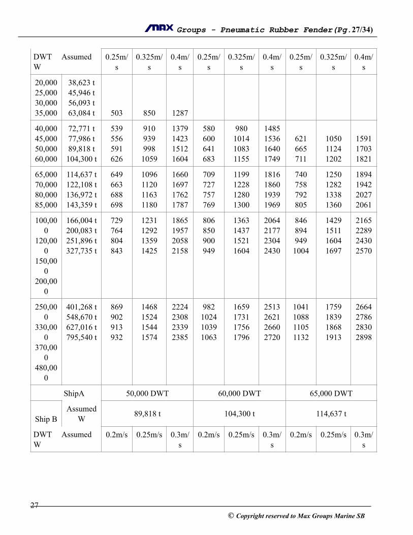
ShipA 50,000 DWT 60,000 DWT 65,000 DWT
!Ship B
Assumed W 89,818 t 104,300 t 114,637 t
DWT Assumed W
0.2m/s 0.25m/s 0.3m/s
0.2m/s 0.25m/s 0.3m/s
0.2m/s 0.25m/s 0.3m/s
! 27© Copyright reserved to Max Groups Marine SB

! Groups - Pneumatic Rubber Fender(Pg. ! /! ) 28 34
!Note: Required quantities are 4 pieces of fender & over. !
(Continued table 11 – Kinetic energy (kJ) at ship-to-ship berthing ) !
40,000 45,000 50,000 60,000
72,771 t 77,986 t 89,818 t
104,300 t
! 458
492
!!716 769
!!1031 1108
!!!532
!!!831
!!!1197
65,000 70,000 80,000 85,000
114,637 t 122,108 t 136,972 t 143,359 t
514 528 553 563
803 825 865 880
1156 1188 1245 1267
557 574 604 616
870 897 944 962
1253 1291 1359 1386
585 603 637 650
914 942 995 1015
1315 1357 1432 1462
100,000
120,000
150,000
200,000
166,004 t 200,083 t 251,896 t 327,735 t
594 632 675 719
929 988 1055 1124
1338 1423 1520 1618
653 699 752 807
1021 1093 1176 1261
1470 1573 1693 1816
692 743 804 866
1081 1162 1256 1354
1556 1673 1808 1949
250,000
330,000
370,000
480,000
401,268 t 548,670 t 627,016 t 795,540 t
749 787 801 823
1170 1230 1252 1286
1684 1771 1803 1852
844 894 912 941
1319 1397 1425 1470
1900 2011 2052 2116
909 967 989 1022
1421 1511 1545 1597
2046 2176 2224 2300
ShipA 70,000 DWT 80,000 DWT 85,000 DWT
!Ship B
Assumed W 122,108 t 136,972 t 143,359 t
DWT Assumed W
0.2m/s 0.25m/s 0.3m/s 0.2m/s 0.25m/s 0.3m/s 0.2m/s 0.25m/s 0.3m/s
! 28© Copyright reserved to Max Groups Marine SB
! Groups - Pneumatic Rubber Fender(Pg. ! /! ) 29 34
65,000 70,000 80,000 85,000
114,637 t 122,108
t 136,972
t 143,359
t
!623 658 673
!973 1029 1051
!1401 1482 1513
!!699 714
!! 1091
1116!
1572 1608
!!!731
!!!1142
!!!1645
100,000
120,000
150,000
200,000
166,004 t
200,083 t
251,896 t
327,735 t
718 773 839 907
1121 1209 1311 1418
1615 1740 1887 2042
765 829 905 985
1196 1296 1414 1540
1722 1866 2036 2217
785 852 932 1017
1226 1331 1456 1589
1765 1917 2097 2289
250,000
330,000
370,000
480,000
401,268 t
548,670 t
627,016 t
795,540 t
955 1019 1042 1080
1492 1592 1629 1687
2149 2292 2346 2429
1042 1118 1147 1192
1627 1747 1792 1862
2344 2516 2580 2682
1077 1159 1190 1239
1683 1811 1860 1936
2424 2609 2678 2788
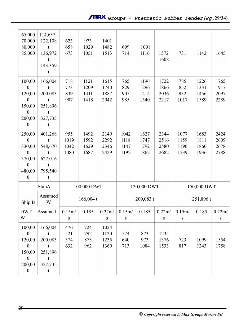
ShipA 100,000 DWT 120,000 DWT 150,000 DWT
!Ship B
Assumed W 166,004 t 200,083 t 251,896 t
DWT Assumed W
0.15m/s
0.185 0.22m/s
0.15m/s
0.185 0.22m/s
0.15m/s
0.185 0.22m/s
100,000
120,000
150,000
200,000
166,004 t
200,083 t
251,896 t
327,735 t
476 521 574 632
724 792 873 962
1024 1120 1235 1360
!574 640 713
!873 973 1084
!1235 1376 1533
!!723 817
!!1099 1243
!!1554 1758
! 29© Copyright reserved to Max Groups Marine SB
! Groups - Pneumatic Rubber Fender(Pg. ! /! ) 30 34
250,000
330,000
370,000
480,000
401,268 t
548,670 t
627,016 t
795,540 t
674 731 753 788
1025 1112 1146 1199
1449 1573 1620 1695
766 841 870 917
1165 1280 1324 1395
1648 1810 1872 1973
888 991 1031 1098
1351 1507 1568 1670
1910 2131 2218 2361
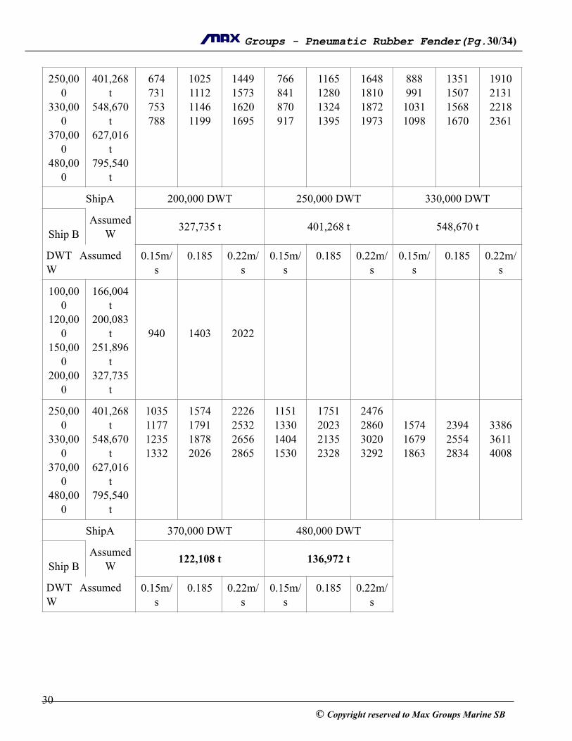
ShipA 200,000 DWT 250,000 DWT 330,000 DWT
!Ship B
Assumed W 327,735 t 401,268 t 548,670 t
DWT Assumed W
0.15m/s
0.185 0.22m/s
0.15m/s
0.185 0.22m/s
0.15m/s
0.185 0.22m/s
100,000
120,000
150,000
200,000
166,004 t
200,083 t
251,896 t
327,735 t
!!!940
!!!1403
!!!2022
250,000
330,000
370,000
480,000
401,268 t
548,670 t
627,016 t
795,540 t
1035 1177 1235 1332
1574 1791 1878 2026
2226 2532 2656 2865
1151 1330 1404 1530
1751 2023 2135 2328
2476 2860 3020 3292
!1574 1679 1863
!2394 2554 2834
!3386 3611 4008
ShipA 370,000 DWT 480,000 DWT
!Ship B
Assumed W 122,108 t 136,972 t
DWT Assumed W
0.15m/s
0.185 0.22m/s
0.15m/s
0.185 0.22m/s
! 30© Copyright reserved to Max Groups Marine SB
! Groups - Pneumatic Rubber Fender(Pg. ! /! ) 31 34
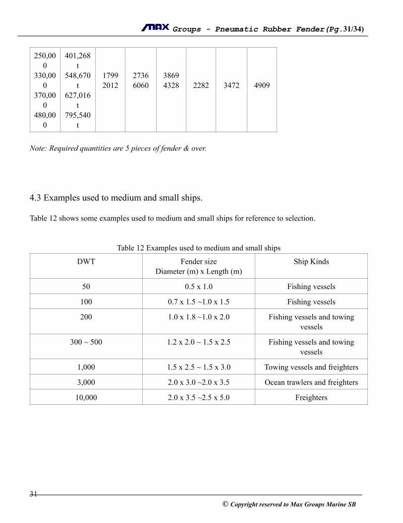
!Note: Required quantities are 5 pieces of fender & over. !!!!4.3 Examples used to medium and small ships. !Table 12 shows some examples used to medium and small ships for reference to selection. !!
Table 12 Examples used to medium and small ships
!!!!!!!!
250,000
330,000
370,000
480,000
401,268 t
548,670 t
627,016 t
795,540 t
!!1799 2012
!!2736 6060
!!3869 4328
!!!2282
!!!3472
!!!4909
DWT Fender size Diameter (m) x Length (m)
Ship Kinds
50 0.5 x 1.0 Fishing vessels
100 0.7 x 1.5 ~1.0 x 1.5 Fishing vessels
200 1.0 x 1.8 ~1.0 x 2.0 Fishing vessels and towing vessels
300 ~ 500 1.2 x 2.0 ~ 1.5 x 2.5 Fishing vessels and towing vessels
1,000 1.5 x 2.5 ~ 1.5 x 3.0 Towing vessels and freighters
3,000 2.0 x 3.0 ~2.0 x 3.5 Ocean trawlers and freighters
10,000 2.0 x 3.5 ~2.5 x 5.0 Freighters
! 31© Copyright reserved to Max Groups Marine SB
! Groups - Pneumatic Rubber Fender(Pg. ! /! ) 32 34
5.0 Operations and Maintenances !5.1 Adjusting internal pressure
5.1.1 Initial Internal pressure
The initial internal pressures of ! floating-type pneumatic rubber fenders are divided into two kinds
upon request of users. This Type A is of 0.05MPa, and the type B is of 0.08MPa.
When charging a fender with air, the user must be first determining the initial pressure according to the
kind of fender purchased. The tolerance of initial pressure should be controlled in the range of ±5%
standard figure.
!!!!!5.1.2 Operation of adjusting internal pressure.
The operation of the valve for air charging is like charging a car tire.
Disassembling the protective cap on the end flange, put a pressure gauge upon the screw-joint coupling,
the pressure gauge shows the data of the internal pressure. If internal pressure being higher than desirable
figure, a discharge operation must be done as follows:-
!!5.1.3 Discharge operation
If needed a large number of discharges, please put the screw of air valve rotation in counterclockwise
direction. If needed a little discharge, please press the core of the air valve for release.
!5.2 Operations for charging
The arrangement of air filling hose and equipments shows in fig. 10 ½”iron pipe is usually used to connect
a pressure accumulator or compressor at one end, and another end connects a control valve, then a
pressure gauge, then an air filling rubber hose connects to the air valve with a nozzle-touch joint. The
pressure of air supply must be more than 0.08MPa.
The operation steps for charging are as follows:-
! 32© Copyright reserved to Max Groups Marine SB

! Groups - Pneumatic Rubber Fender(Pg. ! /! ) 33 34
1) Disassemble the air valve core by means of a special key and insert an air filling rubber hose
connected to the air supply.
2) Open the control valve, charging air until the internal pressure of the fender reach a desirable
figure.
3) Close the control valve, draw air filling rubber hose out and install the air valve core rapidly with a
special key, then disassemble the nozzle-touch joint and assemble the protective cap at the end
flange.
! !Fig. 10 the arrangement of air filling hose and equipments !
5.3 Maintenances
1) Periodically check the fender against damages and pressure variation and replace the air valve core
once every six months.
2) If the fender ties with wire rope, the wire rope must be cased with rubber sleeves to avoid the
fender stabbed by wire.
3) There must be none of sharp or projecting thing on the surface in which the fenders contact to
avoid the fender from being damaged.
5.4 Storage
An unused fender can be well-maintained for a long time if stored in the clear, dry and airy place. The
store must be cool, dark and with good ventilation. The fenders must be kept away from hot condition.
! 33© Copyright reserved to Max Groups Marine SB

! Groups - Pneumatic Rubber Fender(Pg. ! /! ) 34 34
Keep them away from acid, alkali, grease and organic solution. Avoid putting heavy loads on the fenders.
Keep all fenders individually spaced.
!!5.5 Fixtures and fittings
The ! floating-type pneumatic rubber fenders have following fixtures and fittings ready in place
upon leaving the factory (Ex-work):-
1) Air valve core ……………………………. 5 pcs
2) Nozzle-touch joint of air valve ……………1 pc
3) Special key for air valve core ……………...1 pc
4) Rubber hose for filling air …………………0.5 m
5) Pressure gauge ………………………….… 1 pc.
!!
!
!Fig 11 Fixtures and Fitting
! 34© Copyright reserved to Max Groups Marine SB


![[RUBBER MARINE FENDERS] (εισηγμένη)shipsafemarine.com/.../04/RUBBER-MARINE-FENDERS.pdf · a testing protocol compliant with the PIANC 2002 Guidelines for the Design of Fender](https://static.fdocuments.in/doc/165x107/608bf9db28e1a2171262255c/rubber-marine-fenders-f-a-testing-protocol-compliant-with-the.jpg)