Operating Display – Built-In Devices
32
The Drive & Control Company Rexroth IndraControl VEP 07.6/15.6 Multi Touch Operating Display – Built-In Devices Edition 02 Operating Instructions R911341193
Transcript of Operating Display – Built-In Devices

The Drive & Control Company
Rexroth IndraControlVEP 07.6/15.6 Multi TouchOperating Display – Built-In Devices
Edition 02Operating InstructionsR911341193

Bosch Rexroth AG VEP 07.6/15.6 Multi Touch
Change Record
Edition ReleaseDate
Notes
Edition 01 2014-10 First editionEdition 02 2015-03 7” variant supplemented
Copyright
© Bosch Rexroth AG 2015This document, as well as the data, specifications and other information setforth in it, are the exclusive property of Bosch Rexroth AG. It may not be repro-duced or given to third parties without its consent.
Liability
The specified data is intended for product description purposes only and shallnot be deemed to be a guaranteed characteristic unless expressly stipulated inthe contract. All rights are reserved with respect to the content of this documen-tation and the availability of the product.
Editorial Department
Development Automation Systems Control Platform HB (KaWa/MePe)
RS-b0718b7f0170cd7c0a6846a501ccdd57-2-en-US-5

Table of ContentsPage
1 About this documentation..................................................................... 1
2 Product identification and scope of delivery......................................... 22.1 Product identification............................................................................ 22.2 Scope of delivery................................................................................... 3
3 Using safety instructions........................................................................ 33.1 Safety instructions – Structure.............................................................. 33.2 Explaining signal words and safety alert symbol................................... 33.3 Symbols Used........................................................................................ 4
4 Intended use.......................................................................................... 4
5 Spare parts, accessories and wear parts.............................................. 55.1 External 24 V power supply unit............................................................ 55.2 Uninterruptible power supply (UPS)..................................................... 65.3 Wear parts............................................................................................. 6
6 Ambient conditions................................................................................ 6
7 Technical data........................................................................................ 87.1 General technical data........................................................................... 87.2 Optical characteristic values.................................................................. 87.2.1 TFT......................................................................................................... 87.2.2 Input system (multi-touch front)............................................................ 8
8 Standards.............................................................................................. 98.1 General information............................................................................... 98.2 Standards used...................................................................................... 98.3 CE marking............................................................................................. 98.3.1 Declaration of conformity...................................................................... 98.4 UL/CSA certified.................................................................................. 10
9 Interfaces............................................................................................. 119.1 View..................................................................................................... 119.2 Overview.............................................................................................. 119.3 24 V DC voltage supply........................................................................ 12
VEP 07.6/15.6 Multi Touch Bosch Rexroth AGTable of Contents
DOK-SUPPL*-VEPXX.6MTBU-IT02-EN-P I

Page
9.4 USB interfaces..................................................................................... 12
10 Mounting, demounting and electric installation.................................. 1310.1 Housing dimensions............................................................................. 1310.2 Installation notes................................................................................. 1410.3 Assembly.............................................................................................. 1410.4 Mounting dimensions........................................................................... 1710.5 Demounting......................................................................................... 17
11 Commissioning.................................................................................... 18
12 Device description............................................................................... 1812.1 General information............................................................................. 1812.2 Operating and error displays............................................................... 19
13 Error causes and troubleshooting........................................................ 19
14 Maintenance........................................................................................ 1914.1 General information............................................................................. 1914.2 Display................................................................................................. 1914.3 Cleaning notes..................................................................................... 2014.4 Regular maintenance tasks.................................................................. 20
15 Ordering information........................................................................... 2015.1 Accessories and spare parts................................................................ 2015.2 Type code............................................................................................. 21
16 Disposal............................................................................................... 2116.1 Return.................................................................................................. 2116.2 Packaging............................................................................................. 22
17 Service and support............................................................................ 22
Index.................................................................................................... 23
Bosch Rexroth AGTable of Contents
VEP 07.6/15.6 Multi Touch
II DOK-SUPPL*-VEPXX.6MTBU-IT02-EN-P

1 About this documentationOverview on target groups and product phases
In the following illustration, the framed activities, product phases and targetgroups refer to the present documentation.Example: In the product phase "Mounting (assembly/installation)", the "mechan-ic/electrician" can execute the activity "install" using this documentation.
Presales Aftersales
Selection Mounting(assembly/installation) Engineering Commissioning Operation DecommissioningProduct
phases
Targetgroups
Activities
Design engineer
Programmer
Technologist
Processspecialist
Select
Prepare
Design
Construct
Mechanic/electrician
Unpack
Mount
Install
Programmer
Commissioning engineer
Parameterize
Program
Configure
Simulate
Technologist
Process specialist
Optimize
Test
Machineoperator
Maintenancetechnician
Service
Operate
Maintain
Removefaults
Createthe NC program
Mechanic/electrician
Disposal company
Dismount
Dispose
Fig. 1-1: Assigning the present documentation to the target groups, product phases and ac-tivities of the target group
Purpose
This document instructs the technical staff of the machine manufacturer on howto perform the mechanical and electrical installation safely and on how to com-mission the device.Required qualifications: Individual who is able to assess the tasks assigned andidentify possible safety risks owing to qualification in the subject, knowledgeand experience. The individual should also be familiar with the standards andregulations.
Scope
This operating instruction applies to all multi-touch operator displays whosetype code starts with "VEP15.6…" or "VEP 07.6".The type code specifications are located on the type plate of the device. Also re-fer to chapter 2.1 "Product identification" on page 2.
VEP 07.6/15.6 Multi Touch Bosch Rexroth AGAbout this documentation
DOK-SUPPL*-VEPXX.6MTBU-IT02-EN-P 1/27

Related documents
Title Parts number and document typeRexroth IndraControlVAP 01Power Supply Unit
R911339613Operating Instructions
Rexroth IndraControlVAU 01.1UPS with Communication Interface
R911336867Operating Instructions
Rexroth IndraControlV-DevicesOperating Systems
R911343901Project Planning Manual
Tab. 1-1: Related documentation
Customer Feedback
Customer requests, comments or suggestions for improvement are of great im-portance to us. Please email your feedback on the documentations to [email protected]. Directly insert comments in the elec-tronic PDF document and send the PDF file to Bosch Rexroth.
2 Product identification and scope of delivery
2.1 Product identificationThe type plate is located on the rear side or at the side of the device.
Bosch Rexroth AG D-64711 ErbachMad
e in
Ger
man
y
MA6/210-7402-M
UN IN 3AC 230V 50/60 HzIN OUT 10/7,5/5/5/1,5/1,5 A max.
I-C-B-T-VSW-Vers ion V0,002
MNR: 1070086300 -105 04W03
1070
SN: 123456789
13026
2
36
7
7
10
11
12
13
14
98
54
1
Bos
ch re
xrot
h E
lect
ric D
rives
and
Con
trols
Gm
bHD
-647
11 E
rbac
hM
ade
in G
erm
any BTV40.1AHB-256S-P5C-
UN-FW
UN IN 3AC 230V 50760HzIN OUT 10/7,5/5/5/1,5/1,5A max.
I-C-B-T-VSW-Version V0,002
MNR: 1070170021 -101 03W19
7261
IND.CONT.EQ 17YB
SN: 123456814
15
16
Made in Germany
UN: AC 230V / 115VIN: 0,7A / 1,4A
MNR: 1070086255 -101 V-Nr: 1
TYP: PCPNL PEN400J1287 IS110-T
Bosch Rexroth Electric Drives and Controls GmbHD-6471 1 Erbach
SN: 004012652
7261
IND.CONT-EQ 17YBXXXXXXXXXXXXXXXXX
I-C-B-H-T-V
FD: 05W01
1 234
89
5
10
6
12
1113
14
1516
1 Logotype2 Division or plant number3 Type designation code (type code)4 Parts number5 State of revision6 Date of manufacture (yyWww)7 Nominal voltage
8 Nominal current9 Test marking10 Version number11 CE mark12 Underwriters Laboratories Inc. mark13 Serial number as barcode14 Serial number
Bosch Rexroth AGProduct identification and scope of delivery
VEP 07.6/15.6 Multi Touch
2/27 DOK-SUPPL*-VEPXX.6MTBU-IT02-EN-P
http://www.boschrexroth.com/various/utilities/mediadirectory/download/index.jsp?object_nr=R911339612

15 Designation of origin 16 Company addressFig. 2-1: Exemplary type plates
2.2 Scope of delivery● Operator display● Safety instructions● Mounting kit● 24 V female connector strip
3 Using safety instructions
3.1 Safety instructions – StructureThe safety instructions are structured as follows:
Burns and chemical burns due to wrong battery treatment!
CAUTION
Safety alert symbolSignal word
Consequences andsource of danger
Avoiding danger
Do not open the batteries and do not heat them over 80 °C.
Fig. 3-1: Safety instructions – structure
3.2 Explaining signal words and safety alert symbolThe safety instructions in this documentation contain specific signal words (dan-ger, warning, caution, notice) and, if necessary, a safety alert symbol (accordingto ANSI Z535.6-2006).The signal word is used to draw attention to the safety instruction and also pro-vides information on the severity of the hazard.The safety alert symbol (a triangle with an exclamation point), which precedesthe signal words danger,warning and caution is used to alert the reader to per-sonal injury hazards.
DANGER
In the event of non-compliance with this safety instruction, death or serious in-jury will occur.
VEP 07.6/15.6 Multi Touch Bosch Rexroth AGUsing safety instructions
DOK-SUPPL*-VEPXX.6MTBU-IT02-EN-P 3/27

WARNING
In the event of non-compliance with this safety instruction, death or serious in-jury will occur.
CAUTION
In the event of non-compliance with this safety instruction, minor or moderateinjury can occur.
NOTICEIn the event of non-compliance with this safety instruction, material damage canoccur.
3.3 Symbols UsedPointers are displayed as follows:
This is a note.
Tips are displayed as follows:
This is a tip.
4 Intended useThe Bosch Rexroth operator displays are passive operator and visualization ter-minals. They form a PC-based operator terminal when used with a BoschRexroth control cabinet PC.
Bosch Rexroth AGIntended use
VEP 07.6/15.6 Multi Touch
4/27 DOK-SUPPL*-VEPXX.6MTBU-IT02-EN-P

Risk of damaging the device if not expressly sta-ted accessories, mounting parts and other com-ponents, cables, and lines are used.
NOTICE
The operator displays may only be used as intended and with the accessories,mounting parts and other components specified in this documentation. Compo-nents that are not expressly mentioned must neither be attached nor connected.The same applies to cables and lines.Only to be operated with the component configurations and combinations ex-pressly defined and with the software and firmware specified in the correspond-ing functional description.
Typical areas of application of the operator display:● Handling and assembly systems● Packaging and food processing machines● Printing and paper converting machines● Machine tools● Wood processing machinesThe operator displays may only be operated under the mounting and installationconditions, the position and the ambient conditions (temperature, degree ofprotection, humidity, EMC etc.) specified in this documentation.
Danger of destruction of the touch screen if op-erated with inappropriate objects.
NOTICE
Operate the touch screen only with your finger or with a touch pen.
5 Spare parts, accessories and wear parts
5.1 External 24 V power supply unitOrdering code Parts number DescriptionVAP01.1H-W23-024-010-NN R911171065 External 24 V power supply unit for
IndraControl V devices
Tab. 5-1: External 24 V power supply unit for the operator display
VEP 07.6/15.6 Multi Touch Bosch Rexroth AGSpare parts, accessories and wear parts
DOK-SUPPL*-VEPXX.6MTBU-IT02-EN-P 5/27

5.2 Uninterruptible power supply (UPS)Ordering code Parts number DescriptionVAU01.1U-024-024-240-NN R911171024 Uninterruptible power supply
DC 24 V, 240 watts with USB interface
Tab. 5-2: Uninterruptible power supply (UPS)
Ordering code Parts number DescriptionRKB0050/001,0 R911172944 USB connecting cable with increased noise
immunity; length 1 mRKB0050/003,0 R911172945 USB connecting cable with increased noise
immunity; length 3 m
Tab. 5-3: USB connection cable with high noise immunity for UPS
5.3 Wear partsWear parts are not subject to any warranty.
Backlight
The service life of the backlight is limited. After this period, the backlight willproduce only 50 % of its original brightness. The service life of the VEP 15.6 isapprox. 50,000 hours and of the VEP 07.6 approx. 30,000 hours if the ambienttemperature is 25 °C.
6 Ambient conditions In operation Transport StorageMax. ambient tempera-ture
+0 °C to +50 °C -20 °C to +60 °C -20 °C to +60 °C
Max. temperature gradi-ent
Temporal temperaturechanges up to 3 K perminute
Temporal temperaturechanges up to 3 K perminute
Temporal temperaturechanges up to 3 K perminute
Bosch Rexroth AGAmbient conditions
VEP 07.6/15.6 Multi Touch
6/27 DOK-SUPPL*-VEPXX.6MTBU-IT02-EN-P

In operation Transport StorageHumidity Min. relative humidity:
5 %Max. relative humidity:85 %Min. absolute humidity:1 g/m3
Max. absolute humidity:25 g/m3
Condensation not al-lowedCorresponds to climaticclass 3K3 acc. to EN60721-3-3
Min. relative humidity:5 %Max. relative humidity:75 %Min. absolute humidity:1 g/m3
Max. absolute humidity:25 g/m3
Condensation not al-lowedCorresponds to climaticclass 2K2 acc. to EN60721-3-2
Min. relative humidity:5 %Max. relative humidity:85 %Min. absolute humidity:1 g/m3
Max. absolute humidity:25 g/m3
Condensation not al-lowedCorresponds to climaticclass 1K2 acc. to EN60721-3-1
Air pressure Up to 3,000 m abovesea level acc. to EN61131-2
Up to 3,000 m abovesea level acc. to EN61131-2
Up to 3,000 m abovesea level acc. to EN61131-2
Mechanical strength Max. vibration:Frequency range:10 … 150 HzExcursion: 0.75 mm at10 … 57 HzAcceleration: 1 g at57 ... 150 HzAcc. to EN 600068-2-6
Max. shock:15 g 11 msacc. to EN 60068-2-27,No malfunction
Max. shock:15 g 11 msacc. to EN 60068-2-27,No malfunction
Contamination level 2 2 2Overvoltage category 2 - -
Tab. 6-1: Ambient conditions
The ambient air must not contain acids, alkaline solutions, corrosiveagents, salts, metal vapors and other electrically conductive contam-inants in high concentrations.The ambient air must be free of dust. Housing and installation com-partments must at least comply with the degree of protection IP 54acc. to DIN VDE 0470-1.
Not resistant to gas endangering the function (sulphur dioxide(SO2), hydrogen sulphide (H2S))
VEP 07.6/15.6 Multi Touch Bosch Rexroth AGAmbient conditions
DOK-SUPPL*-VEPXX.6MTBU-IT02-EN-P 7/27

7 Technical data
7.1 General technical data VEP15.6GA VEP07.6CKDisplay 396 mm TFT (15")
1366 × 768 pixels16.7 million colors
17 mm TFT (7")800 x 480 pixels262k colors
Operation Multi touchSurface of the front panel Thermally tempered glassDegree of protection Front panel IP 65 acc. to DIN EN 60 529
Front type 1 acc. to NEMA (UL)Rear side IP 20
Voltage supply DC 24 V (use a 24 V power supply unit acc. to DIN EN 60742, classificationVDE 0551, for example the VAP01.1H-W23-024-010-NN, parts numberR911171065)
Current consumption 1.5 A for 24 V DC 1.1 A for 24 V DCPower loss 36 W 26 WUSB Per USB port max. 500 mA, total current at all USB ports max. 1 A.Weight 5.35 kg 4.2 kg
Tab. 7-1: Technical data of the VEP 15.6 and VEP 07.6
7.2 Optical characteristic values
7.2.1 TFTThe maximum permissible number and type of pixel errors of TFT displays de-pends on the manufacturer and is defined by the respective "incoming inspec-tion" of the manufacturer. This "incoming inspection" is provided by the BoschRexroth service if required.The maximum brightness and color characteristics of TFT displays depends onthe manufacturer and is defined by the respective specification of the manufac-turer.
7.2.2 Input system (multi-touch front)The maximum permissible number and type of defects on the front or the glass,such as trapped dust, scratches, etc. is defined in the FT1) . The VEP multi-touchdevices meet the quality guideline.
1) Quality standard (version December 2013) of the Fachgemeinschaft Eingabesysteme (Germanassociation for input systems).
Bosch Rexroth AGTechnical data
VEP 07.6/15.6 Multi Touch
8/27 DOK-SUPPL*-VEPXX.6MTBU-IT02-EN-P

8 Standards
8.1 General informationThe products have been developed according to the German edition of thestandards published at the time of product engineering.
8.2 Standards usedStandard SignificanceEN 60 204-1 Safety of machinery - Electrical equipment of machinesEN 61 000-6-4 Generic standards - Emission standard (industrial environments)EN 61 000-6-2 Generic standards – Noise immunity (industrial environments)EN 61 558-2-6 Transformer for 24 V power supply unit, protective separationEN 60 664-1 Overvoltage category IIEN 61 131-2 24 V output requirementsEN 61 131-2 24 V current supply requirementsEN 60 529 Degrees of protection (including housings and installation com-
partments)EN 60 068-2-6 Vibration testEN 60 068-2-27 Shock testEN 60 721-3-1 andEN 60 721-3-3
Climatic class
Tab. 8-1: Standards used
8.3 CE marking
8.3.1 Declaration of conformity
The electronic products described in the present operating instructions complywith the requirements and the target of the following EU directive and with thefollowing harmonized European standards:EMC Directive 2004/108/ECThe electronic products described in the present operating instructions are in-tended for use in industrial environments and comply with the following require-ments:
VEP 07.6/15.6 Multi Touch Bosch Rexroth AGStandards
DOK-SUPPL*-VEPXX.6MTBU-IT02-EN-P 9/27

Standard Title EditionDIN EN 61000-6-4(VDE 0839-6-4)
Electromagnetic Compatibility (EMC)Part: 6-4: Generic standards – Emission standard for indus-trial environments (IEC 61000-6-4:2006)
September 2007
DIN EN 61000-6-2(VDE 0839-6-2)
Electromagnetic Compatibility (EMC)Part: 6-2: Generic standards – Noise immunity for industrialenvironments (IEC 61000-6-2:2005)
March 2006
Tab. 8-2: Standards for electromagnetic compatibility (EMC)
Non-compliance with CE conformity due to modifications at the de-vice.The CE marking is only valid for the device in its delivery state. Aftermodifying the device, verify CE conformity.
8.4 UL/CSA certified
The devices are certified according to● UL508 (Industrial Control Equipment) and● C22.2 No. 142-M1987 (CSA)UL file no. E210730However, there can be combinations or extension stages with a limited or miss-ing certification. Thus, verify the registration according to the UL marking on thedevice.
Loss of UL/CSA conformity due to modifications at the device.UL and CSA marking applies only to the device in its delivery state.After modifying the device, UL conformity and CSA conformity are tobe verified.
Bosch Rexroth AGStandards
VEP 07.6/15.6 Multi Touch
10/27 DOK-SUPPL*-VEPXX.6MTBU-IT02-EN-P
9 Interfaces
9.1 View
1 2 3 4 5
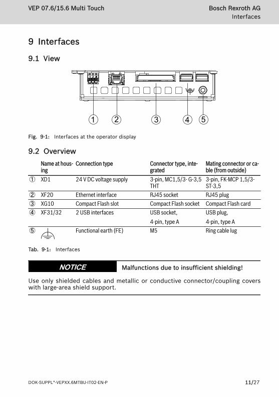
Fig. 9-1: Interfaces at the operator display
9.2 Overview Name at hous-
ingConnection type Connector type, inte-
gratedMating connector or ca-ble (from outside)
① XD1 24 V DC voltage supply 3-pin, MC1,5/3- G-3,5THT
3-pin, FK-MCP 1,5/3-ST-3,5
② XF20 Ethernet interface RJ45 socket RJ45 plug③ XG10 Compact Flash slot Compact Flash socket Compact Flash card④ XF31/32 2 USB interfaces USB socket,
4-pin, type AUSB plug,4-pin, type A
⑤ Functional earth (FE) M5 Ring cable lug
Tab. 9-1: Interfaces
Malfunctions due to insufficient shielding!NOTICEUse only shielded cables and metallic or conductive connector/coupling coverswith large-area shield support.
VEP 07.6/15.6 Multi Touch Bosch Rexroth AGInterfaces
DOK-SUPPL*-VEPXX.6MTBU-IT02-EN-P 11/27

9.3 24 V DC voltage supply
Fig. 9-2: Interface for 24 V voltage supply
Pin Function1 +24 V supply voltage2 0 V supply voltage3 n.c.
Use a 24 V industrial power supply unit acc. to DIN EN 60742, classification VDE0551, for example "VAP01.1H-W23-024-010-NN" (parts number R911171065) forthe voltage supply.
9.4 USB interfacesThere are two USB interfaces on the connector panel (XUSB1/2) at the devicesand, depending on the variant, one interface on the front panel.
Operating USB ports at operator display
Interference-free USB2.0 connection only up to a cable length of 5meters.
Connect only USB devices that meet the USB2.0 specification.
The cables of the connected USB devices have to comply with theUSB2.0 specifications.
If the total current of all USB ports exceeds 1 A, the power supplyunit switches off the operator display.
Bosch Rexroth AGInterfaces
VEP 07.6/15.6 Multi Touch
12/27 DOK-SUPPL*-VEPXX.6MTBU-IT02-EN-P

10 Mounting, demounting and electric installation
10.1 Housing dimensions
346 mm 422 mm
195
mm
44 m
m36
mm
275
mm
1
38 mm
① Visual range of the displayFig. 10-1: Housing dimensions of the operator display VEP 15.6
154 mm220 mm
33 mm
1
33 mm
35,5
mm
93 m
m15
8 m
m29
,5 m
m
① Visual range of the displayFig. 10-2: Housing dimensions of the operator display VEP 07.6
VEP 07.6/15.6 Multi Touch Bosch Rexroth AGMounting, demounting and electric installation
DOK-SUPPL*-VEPXX.6MTBU-IT02-EN-P 13/27

10.2 Installation notes● Provide a space of 50 mm on all sides of the device for sufficient cooling and
cable routing● The LED display on the operator panel must not be covered.● Wire all cables in loops. Use strain reliefs for all cables● Only install the operator display vertically, with a max. deviation of ±45°,
measured from the vertical
10.3 AssemblyMount the operator display as follows:
Loss of degree of protection IP 65!The housing, in which the operator display is installed, has to fulfillthe following conditions:● Free from impurities● Sufficient mechanical strength and flatnessThese criteria influence the required degree of protection IP to agreat extent.Further required measures are to be taken depending on the mount-ing location, e. g. the stabilization of the mounting frame.
1. Creating a mounting cut-out, see chapter 10.4 "Mounting dimensions" onpage 17.
2. Insert the operator display from the front into the cut-out until the latchinglug at the top of the device latches in the cut-out.
Bosch Rexroth AGMounting, demounting and electric installation
VEP 07.6/15.6 Multi Touch
14/27 DOK-SUPPL*-VEPXX.6MTBU-IT02-EN-P

21 1 1
1
1
11
1
1
1
① Clamp fastenings② Latching lugFig. 10-3: Position of clamp fastenings for the VEP 15.6
21
1
1
1
① Clamp fastenings② Latching lugFig. 10-4: Position of clamp fastenings for the VEP 07.6
3. Fold out the clamp fastenings.
VEP 07.6/15.6 Multi Touch Bosch Rexroth AGMounting, demounting and electric installation
DOK-SUPPL*-VEPXX.6MTBU-IT02-EN-P 15/27

Fig. 10-5: Clamp fastening
4. Tighten the clamping screws.
Mechanic damage due to incorrect mountingtorque.
NOTICE
Tighten the screws and nuts with the corresponding torque according to the fol-lowing table.
Threads Mounting torqueM2,5 0.4 NmM3 0.7 NmM4 1.4 NmM5 1.0 Nm
Tab. 10-1: Mounting torques
Bosch Rexroth AGMounting, demounting and electric installation
VEP 07.6/15.6 Multi Touch
16/27 DOK-SUPPL*-VEPXX.6MTBU-IT02-EN-P

10.4 Mounting dimensions
1
AB
① Mounting cut-outFig. 10-6: Fitting dimensions
Operator display Dimension A Dimension BVEP 15.6 403 255VEP 07.6 203 140
Tab. 10-2: Dimensions of the mounting cut-out (in mm)
10.5 Demounting1. Disconnect the operator display.2. Remove all connected cables.3. Loosen the screws of the clamp fastenings.4. Fold the clamp fastenings.5. Press the latching lug of the installation aid.
Fig. 10-7: Latching lug
6. Remove the operator display from the mounting frame.
VEP 07.6/15.6 Multi Touch Bosch Rexroth AGMounting, demounting and electric installation
DOK-SUPPL*-VEPXX.6MTBU-IT02-EN-P 17/27

11 CommissioningThe product can be used directly. No configuration is required.
12 Device description
12.1 General information
1① Status displaysFig. 12-1: Front view of the operator display VEP 15.6
1
① Status displaysFig. 12-2: Front view of the operator display VEP 07.6
Bosch Rexroth AGDevice description
VEP 07.6/15.6 Multi Touch
18/27 DOK-SUPPL*-VEPXX.6MTBU-IT02-EN-P

12.2 Operating and error displaysAn LED for the operating display is located in the lower part of the front panel.
Symbol,LED
Display Significance Action
Power
LED green Normal operation –LED off No supply voltage of 24 V DC Check supply voltage
Tab. 12-1: LED for operating and error display on the front panel
13 Error causes and troubleshootingFor information on the error display on the front panel, refer to chapter 12.2 "Operating and error displays" on page 19.
Error TroubleshootingNo screen visible ● Connect the supply voltage and check the XD1 connec-
tion● Plug in the Compact Flash card correctly● Use fitting Compact Flash card
The USB flash drive does not work, al-though other USB devices work
● Use USB stick formatted with FAT16 or FAT32
Tab. 13-1: Error causes and troubleshooting
14 Maintenance
14.1 General information
Loss of IP degree of protection due to incorrectmaintenance.
NOTICE
Ensure the IP degree of protection during maintenance!
14.2 DisplayThe backlight is subject to wear, see chapter 5.3 "Wear parts" on page 6.A fading backlight causes a progressive deterioration display readability. Thus, areplacement is necessary. For further information, please contact the BoschRexroth Service.
VEP 07.6/15.6 Multi Touch Bosch Rexroth AGMaintenance
DOK-SUPPL*-VEPXX.6MTBU-IT02-EN-P 19/27

14.3 Cleaning notes
Dissolving front glass sealing with solvent!NOTICE● Do not use solvents● Do not use high pressure cleaning device
14.4 Regular maintenance tasks● Check all plug and terminal connections of the components for proper tight-
ness and possible damage at least once a year● Check that no cables are broken or pinched● Replace damaged parts immediately
15 Ordering information
15.1 Accessories and spare partsFor ordering information on accessories and spare parts, refer to chapter 5 "Spare parts, accessories and wear parts" on page 5.
Bosch Rexroth AGOrdering information
VEP 07.6/15.6 Multi Touch
20/27 DOK-SUPPL*-VEPXX.6MTBU-IT02-EN-P

15.2 Type code
1 2 3 4 5 6 7 8 9 0 Example:
VEP ......... = VEP
15 ......................... = 15
Short textcolumn
Product
Line
6 ...................................... = 6Design
Front panel and display
Customized design15", Multitouch-Screen = GA
Additional optionNone ......................................... = NMemory capacity (RAM)2 GB ................................................ = 2G0
InterfaceET-NN ........................................................ = NESystem configurationIntel Atom N455, min. 1,66 GHz.............................. = A3
Supply voltageDC 24 V .......................................................................... = D
Onboard Flash size8 GB ..................................................................................... = 8G0
Other designNone .................................................................................................... = NN
Firmware and software
V E P 1 5 . 6 G A N - 2 G 0 N E - A 3 D - 8 G 0 - N N - F W1 2 3 4 5 6 7 8 9 0
11 2 3 4 5 6 7 8 9 0
21 2 3 4 5
3
07 ......................... = 07
Bosch: 7", Multitouch-Screen = CK
Rexroth Design
Denotes that firmware and software must be ordered as separate subposition = FW
Fig. 15-1: Type code
16 Disposal
16.1 ReturnFor disposal, our products can be returned free of charge. However, the prod-ucts must be free of remains like oil and grease or other impurities.
VEP 07.6/15.6 Multi Touch Bosch Rexroth AGDisposal
DOK-SUPPL*-VEPXX.6MTBU-IT02-EN-P 21/27

Furthermore, the products returned for disposal must not contain any undue for-eign substances or components.Send the products free of charge to the following address: Bosch Rexroth AG Electric Drives and Controls Bürgermeister-Dr.-Nebel-Straße 2 D-97816 Lohr am Main, Germany
16.2 PackagingThe packaging material consists of cardboard, plastics, wood or styrofoam.Packaging material can be recycled anywhere.For ecological reasons, please do not return empty packages to Bosch Rexroth.
17 Service and supportOur worldwide service network provides an optimized and efficient support.Our experts offer you advice and assistance should you have any queries. Youcan contact us 24/7.
Service Germany
Our technology-oriented Competence Center in Lohr, Germany, is responsiblefor all your service-related queries for electric drive and controls.Contact the Service Hotline and Service Helpdesk under:
Phone: +49 9352 40 5060Fax: +49 9352 18 4941E-mail: [email protected]: http://www.boschrexroth.com/Additional information on service, repair (e.g. delivery addresses) and trainingcan be found on our internet sites.
Service worldwide
Outside Germany, please contact your local service office first. For hotline num-bers, refer to the sales office addresses on the internet.
Preparing information
To be able to help you more quickly and efficiently, please have the following in-formation ready:● Detailed description of malfunction and circumstances● Type plate specifications of the affected products, in particular type codes
and serial numbers● Your contact data (phone and fax number as well as your e-mail address)
Bosch Rexroth AGService and support
VEP 07.6/15.6 Multi Touch
22/27 DOK-SUPPL*-VEPXX.6MTBU-IT02-EN-P

Index0 … 924 V DC voltage supply................. 1224 V voltage supply....................... 12
AAccessories..................................... 5Ambient conditions......................... 6ANSI Z535.6-2006........................... 3
BBacklight......................................... 6
CCE marking..................................... 9Cleaning notes.............................. 20Commission.................................. 18Complaints..................................... 2Connector panel........................... 11Criticism......................................... 2Customer Feedback........................ 2
DDeclaration of conformity............... 9Demounting............................ 13, 17Device description........................ 18Dimensions................................... 17Disposal........................................ 21Documents, related........................ 2
EError causes.................................. 19Error displays................................ 19External 24 V power supply unit..... 5
FFeedback........................................ 2
HHazard warnings............................. 3Helpdesk....................................... 22Hotline.......................................... 22Housing dimensions...................... 13
IInstallation notes.......................... 14Intended use................................... 4Interfaces...................................... 11
XUSB interfaces....................... 12
LLED............................................... 19
MMaintenance................................. 19Mounting....................................... 13Mounting cut-out.......................... 17Mounting dimensions................... 17
N24 V power supply unit................... 5
OOperating and error displays........ 19Optical characteristic values........... 8
PProduct identification..................... 2
SSafety alert symbol......................... 3Safety instructions.......................... 3Scope of delivery............................ 3Service hotline.............................. 22Service life
Backlight.................................... 6Signal words................................... 3Spare parts..................................... 5Standards....................................... 9Suggestions.................................... 2Support........................................ 22Symbols.......................................... 4
TTarget groups.................................. 1Technical data................................. 8
Voltage supply......................... 12Type plate....................................... 2
VEP 07.6/15.6 Multi Touch Bosch Rexroth AGIndex
DOK-SUPPL*-VEPXX.6MTBU-IT02-EN-P 23/27

UUL/CSA certified........................... 10Uninterruptible power supply......... 6UPS................................................. 6USB interfaces.............................. 12Use, intended.................................. 4
VVoltage supply............................... 12Voltage supply (24 V DC).............. 12
WWarnings......................................... 3Wear parts...................................... 5
XXUSB interfaces............................ 12
Bosch Rexroth AGIndex
VEP 07.6/15.6 Multi Touch
24/27 DOK-SUPPL*-VEPXX.6MTBU-IT02-EN-P

VEP 07.6/15.6 Multi Touch Bosch Rexroth AG
DOK-SUPPL*-VEPXX.6MTBU-IT02-EN-P 25/27

Bosch Rexroth AG VEP 07.6/15.6 Multi Touch
26/27 DOK-SUPPL*-VEPXX.6MTBU-IT02-EN-P

Notes
VEP 07.6/15.6 Multi Touch Bosch Rexroth AG

The Drive & Control Company
Bosch Rexroth AG Electric Drives and Controls P.O. Box 13 57 97803 Lohr, Germany Bgm.-Dr.-Nebel-Str. 2 97816 Lohr, Germany Tel. +49 9352 18 0 Fax +49 9352 18 8400 www.boschrexroth.com/electrics
DOK-SUPPL*-VEPXX.6MTBU-IT02-EN-P