OPERATING AND MAINTENANCE MANUAL - Caleffi · - Screen: stainless steel - Seals: EPDM Shut-off ball...
8
HYDROFILL ™ Hydronic water treatment filling units NA10439.01 NA5709 series OPERATING AND MAINTENANCE MANUAL © Copyright 2018 Caleffi www.caleffi.com Function HYDROFILL™ is a water treatment filling unit that produces from site sourced water, demineralized water of an ideal grade for use in closed hydronic heating and cooling systems. Salts and other soluble minerals are almost entirely eliminated so as to prevent premature equipment malfunction including reduced efficiency or component failure due to lime scale formation – a common affliction of heat exchangers. The treated water results in low electrical conductivity to minimize corrosion due to galvanic attack. Also, by eliminating the variability of site produced water having different mineral content values from location to location, using treated water makes for more reliable dosing when chemical additives are used – such as glycol. Product range Code NA570912 Filling unit including two resin filter bags 6 gpm filling rate Code NA570924 Filling unit with cart including four resin filter bags 12gpm filling rate Code NA570971 Two prepacked resin filter bags in plastic bucket with lid Code NA570974 Four prepacked resin filter bags in plastic bucket with lid Technical specifications Filling unit body - Body and cover: PP-H A GF50 - Screen: stainless steel - Seals: EPDM Shut-off ball valve - Body: brass - Ball: stainless steel - Seals: EPDM TDS meter - Range: 0-999 ppm - Resolution: 1 ppm - Accuracy: ±2% - Battery: 2 x 1.5V button cell (LR44/ 357A) - Battery life: approx. 1000 hours Filling unit cart - Frame and hardware: stainless steel - Wheels: semi pneumatic rubber Prepacked filter bags Material: - Bag: nylon - Contents: mixed bed exchange resins Filter resin capacity: - Two bags: 0.42 cu. ft. - Four bags: 0.84 cu. ft. Performance Medium: tap water Maximum working pressure: 120 psi Working temperature range: 40 – 100°F Storage temperature range: 15°F – 120°F TDS of water after treatment: < 30 ppm Connections: 3/4” GHT This item is designed for use in closed hydronic systems. Do not use in plumbing applications. This item does not meet the low-lead plumbing standards of U.S. and Canada.
Transcript of OPERATING AND MAINTENANCE MANUAL - Caleffi · - Screen: stainless steel - Seals: EPDM Shut-off ball...

HYDROFILL™ Hydronic water treatment fi lling units
NA10439.01
NA5709 series
OPERATING AND MAINTENANCE MANUAL
© Copyright 2018 Caleffi
www.caleffi.com
FunctionHYDROFILL™ is a water treatment fi lling unit that produces from site sourced water, demineralized water of an ideal grade for use in closed hydronic heating and cooling systems. Salts and other soluble minerals are almost entirely eliminated so as to prevent premature equipment malfunction including reduced effi ciency or component failure due to lime scale formation – a common affl iction of heat exchangers. The treated water results in low electrical conductivity to minimize corrosion due to galvanic attack. Also, by eliminating the variability of site produced water having different mineral content values from location to location, using treated water makes for more reliable dosing when chemical additives are used – such as glycol.
Product rangeCode NA570912 Filling unit including two resin fi lter bags
6 gpm fi lling rate
Code NA570924 Filling unit with cart including four resin fi lter bags 12gpm fi lling rate
Code NA570971 Two prepacked resin fi lter bags in plastic bucket with lidCode NA570974 Four prepacked resin fi lter bags in plastic bucket with lid
Technical specifi cations
Filling unit body - Body and cover: PP-H A GF50
- Screen: stainless steel- Seals: EPDM
Shut-off ball valve- Body: brass - Ball: stainless steel- Seals: EPDM
TDS meter- Range: 0-999 ppm- Resolution: 1 ppm- Accuracy: ±2% - Battery: 2 x 1.5V button cell (LR44/ 357A)- Battery life: approx. 1000 hours
Filling unit cart - Frame and hardware: stainless steel- Wheels: semi pneumatic rubber
Prepacked fi lter bags Material:
- Bag: nylon- Contents: mixed bed exchange resins
Filter resin capacity:- Two bags: 0.42 cu. ft. - Four bags: 0.84 cu. ft.
PerformanceMedium: tap water Maximum working pressure: 120 psiWorking temperature range: 40 – 100°FStorage temperature range: 15°F – 120°FTDS of water after treatment: < 30 ppmConnections: 3/4” GHT
This item is designed for use in closed hydronic systems. Do not use in plumbing applications. This item does not meet the low-lead plumbing standards of U.S. and Canada.

IMPORTANT
The following instructions must be read and understood before connecting, operating and servicing the Hydrofill water treatment filling unit.
The safety symbol is used in this manual to draw attention to safety instructions. The meaning of this symbol is as follows: CAUTION! YOUR SAFETY IS INVOLVED. FAILURE IN FOLLOWING THESE INSTRUCTIONS MAY RESULT IN INJURY.
• The Hydrofill unit for filling closed loop hydronic systems, must be operated by aqualified technician in compliance with relevant national and/or local regulations.
• If the Hydrofill unit is not connected, operated and serviced correctly in accordancewith the instructions given in this manual, it could malfunction and endanger the user.Contents under pressure can cause severe injury or death from tank rupture.
• Check system for cracks and make sure that all connection fittings are leak-tight.• Be sure cover is in locked position.• Do not exceed pressure of 120 psi. When making the water pressure connections,
ensure that threads are not mechanically overstressed. Over time, excessive stressmay cause breakages with water leaks and damage to property and/or injury ofpersons.
• During connecting, operating and servicing take the necessary precautions to preventinjury to persons caused by high water temperatures.
• When starting to fill, keep discharge line open and hold yellow lever down to removetrapped air from system.
• Before servicing unit, shut off tap water supply and open discharge line.• Disconnect tap water supply and allow tank to drain.• If unit will be idle for a period of time, ensure the tap water supply is shut off.• During transportation, ensure the unit is properly secured.
Intended use:
• The HYDROFILL unit may cause danger if it is improperly connected, not regularlymaintained or not used as intended. Use this unit for water treatment to reach anoptimal water quality for filling a closed loop hydronic system. Any other use, especiallywater treatment for food production or drinking water consumption is prohibited.
• The HYDROFILL unit is intended as a temporary only connection to the tap watersupply and should not be connected for longer than 12 hours to a tap water supply.
• Tap water supply connections may require a hose bib vacuum breaker valvedepending on local codes to prevent back siphonage into tap water supply.
• When operating with site tap water, a water analysis must be performed prior to start-up to determine if water source is suitable. Excess impurities may have a adverseeffect on the HYDROFILL performance.
• When temperatures fall below 32F, drain water from the tank, store and transport inheated vehicles to prevent freezing, which may damage unit.
2
WARNING: This product can expose you to chemicals including lead, which is known to the State of California to cause cancer and birth defects or other reproductive harm. For more information go to www.P65Warnings.ca.gov.
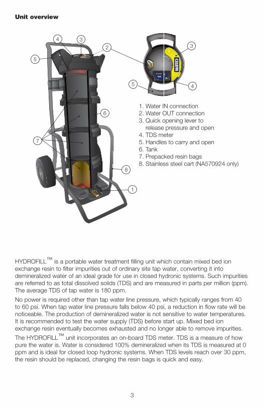
1. Water IN connection2. Water OUT connection3. Quick opening lever to release pressure and open 4. TDS meter5. Handles to carry and open6. Tank7. Prepacked resin bags8. Stainless steel cart (NA570924 only)
1
2
34
5
6
7
8
3
45
Unit overview
HYDROFILL™ is a portable water treatment fi lling unit which contain mixed bed ion exchange resin to fi lter impurities out of ordinary site tap water, converting it into demineralized water of an ideal grade for use in closed hydronic systems. Such impurities are referred to as total dissolved solids (TDS) and are measured in parts per million (ppm). The average TDS of tap water is 180 ppm.
No power is required other than tap water line pressure, which typically ranges from 40 to 60 psi. When tap water line pressure falls below 40 psi, a reduction in fl ow rate will be noticeable. The production of demineralized water is not sensitive to water temperatures. It is recommended to test the water supply (TDS) before start up. Mixed bed ion exchange resin eventually becomes exhausted and no longer able to remove impurities.
The HYDROFILL™ unit incorporates an on-board TDS meter. TDS is a measure of how pure the water is. Water is considered 100% demineralized when its TDS is measured at 0 ppm and is ideal for closed loop hydronic systems. When TDS levels reach over 30 ppm, the resin should be replaced, changing the resin bags is quick and easy.
3

Large yellow lever enables quick and easy opening of the tank. Lever includes a pressure release valve. In one motion as the lid is turned to the full open position, the tank depressurizes and opens to the full diameter of the tank.
Prepacked resin bags save time and simplify resin change process. No more time-consuming, inconvenient fi lling up of narrow tanks and no more spilled, wasted resin. Resin change process is simple as removing the used bags and inserting new ones. Each bag is made from a water permeable material and contains a proportioned amount of high capacity premium grade virgin mixed bed resin.
Innovative fl ow distribution screen design evenly distributes the inlet water through the entire column of resin, eliminating water channels (these channels allow untreated water to bypass through) in standard tanks. Produces up to 30% more treated water from a single resin refi ll compared to other types of demineralization tanks. Reduced operational cost through less frequent resin replacement. Less waste, less time spent on changing resin.
Highly accurate built-in TDS meter 0 - 999 ppm with resolution of 1 ppm due to its advanced microprocessor technology. Auto-Off function conserves battery power. The unit shuts off automatically after 10 minutes of non-use. Replaceable battery with a life of approximately 1000 hours of continuous use.
Construction details
Standard tankWater channels allow untreated water to pass through the resin.
HYDROFILL™Water fl ows evenly through the entire column of resin treating 100% of water.
4

Start-Up
1. Locate job site tap water supply.
2. Before system fi lling can begin, the unit must be connected to a tap water supply. Ifwell water system is the source, it is recommended that a water quality analysis beperformed prior to application.
3. Caleffi recommends testing the water supply for TDS (total dissolved solids) prior tofi lling. Higher TDS levels reduce the unit‘s capacity. Conversely, lower TDS levels willincrease the amount of water the unit is able to produce.
4. Inspect system – ensure the resin bag are properly installed, with zip-tie facing up.
a. NOTE: Caleffi does not recommend the use of bulk resin with HYDROFILL unit. Theuse of bulk resin, with its widely varying properties, may cause damage to the unit dueto excessive expansion when water is introduced. Overfi lling the unit with too muchresin will also cause damage.
b. HYDROFILL's prepacked resin bags are designed to allow a controlled resinexpansion within a designed safety limit.
5. Set up system in upright position. Choose a stable on-site location; best to locate nearwork area.
6. Connect hoses to unit (tap water and hydronic system purging / fi ll valve). Bottomconnection is for tap water supply, top connection is for hydronic system inlet purging/ fi ll valve. Caleffi recommends connecting the largest possible inside diameter hoseswith ¾" GHT. Smaller inside diameter hose will reduce fi ll fl ow rates.
7. Ensure hydronic system fi ll on/off valve is in “OPEN” position.
8. Turn feed water supply “ON” slowly.
9. Inspect system as it pressurizes and begins producing demineralized. Keep dischargehose open and hold down yellow opening lever to remove trapped air from unit. Useonly with tap water.
10. Turn on TDS meter and inspect demineralized water quality. A reading below 30 ppmis best and indicates the system is running properly. Caleffi recommends changingresin bags when TDS levels reach 30 ppm.
11. Adjust water fl ow at on/off valve at the inlet base of unit.
12. You are ready to start fi lling hydronic system.
5

open
closed
open
demineralizedwater
untreatedwater
pressurized site tap
water
inlet purging valve outlet purging valve
TDS meter
The HYDROFILL™ unit is connected as shown on the left. Untreated water from a pressurized site tap passes through a inlet hose connected to the bottom hose connection on the unit. It is demineralized as it flows upward through the resin beads and exits from the upper hose connection. It flows through another hose to the inlet purging valve on the hydronic system. As the demineralized water enters the system, air is pushed out through the open outlet purging valve. A hose from this valve is routed to a clean pail or barrel to capture any water leaving the system during purging. Maintain flow through the unit into the system until a steady stream of water exits the outlet purging valve. The bulk air should now be purged from the system. Close the inlet and outlet purging valves simultaneously. During fill and purging, periodically check the TDS meter on the unit to verify that it does not rise above 30 PPM.
Once-through filling method
In tap water, gases such as oxygen and carbon dioxide are attached to minerals. Demineralization removes most minerals from water, but it does not remove dissolved gases including oxygen and carbon dioxide. When the gases are released, carbon dioxide gas will combine with the demineralized water to form a very weak carbonic acid (H2CO3), which lowers the water’s pH. Removing these gases will increase and stabilize the pH of the demineralized water.Therefore, once the demineralization process has been completed, the system should be operated with the heat source on and all air separation and venting devices active. Whenever possible, the heat source should produce an outlet temperature of 140ºF or higher. This heating and circulation should be maintained for at least one hour. Raising the temperature of the system water helps force dissolved gases out of solution. These gas molecules will coalesce to form micro-bubbles that can be captured by a high-performance air separator, such as a DISCAL, and ejected from the system.
Purging gases from the system
6

Recirculation fi lling methodWhen the fi ll fl ow rate needed to purge the air from the system is more than the maximum allowable fl ow rate through the HYDROFILL™, the system can be demineralized after site water is fi lled into the system. A hose connects from the outlet purging valve on the system to the lower inlet connection on the unit. Another hose connects from the upper outlet on the unit to the inlet purging valve on the system. Open the outlet purging valve to allow water to fl ow from the system into the bottom inlet of the unit. The water will fl ow up through the resin bead column, hold the yellow lever down to release the air inside the unit. Top outlet hose connects to the inlet purging valve. The in-line ball valve between the inlet and outlet purging valve should be partially closed to force some fl ow through the unit.Turn on the system circulator(s) to create fl ow in the system. The TDS reading on the HYDROFILL monitor is
that of the water leaving the unit and not all the water in the system. Allow this recirculation fl ow to continue for several minutes. Then, draw a sample of system water from another drain valve in the system into a clean plastic or glass cup. Test the TDS level of this sample using a hand-held meter.
open
partially closed ONop
eninlet purging valve
outlet purging valveTDS meter
watersample valve
open
partially closed
open
larger pipe diameter
TDStesting
7

Changing resin bags
1. Shut off tap water supply spigot
a. Shut off tap water supply spigot and disconnect thetop discharge fi ll hose.
b. Disconnect bottom supply water hose and openthe bottom on/off valve to allow the unit to drain.
2. Remove top cap assembly
a. Depress yellow opening lever to release systempressure.
b. Fix the base of the unit with your feet, then pressthe top cap down and with a counterclockwise 1/4turn to release top cap assembly. Remove and setaside. Tip: Open the bottom on/off valve to allow easyremoval of resin bags.
c. Reach into housing and remove exhausted resinbags by hand; dispose in recyclable trash.
3. Replace resin
a. Install new resin bags by hand – be sure to placebags with zip-tie facing up and sewing parallel tovessel top edge. Pat down the top of bags by hand toensure seated properly.
b. Inspect system head assembly: O-ring and fl ow distribution screen are in good condition. Re-coatO-ring with silicone lubricant only.
c. Re-install cap assembly. Secure unit with your feet,then press down with a 1/4 turn clockwise.
d. System is ready to be operated.
4. Reconnect water feed hose
a. Turn “ON“ tap water supply at spigot.
b. Inspect unit as it pressurizes.
c. Keep discharge fi ll hose loose and hold downyellow lever to remove trapped air from unit.
5. Test fl ow TDS
TDS
MO
NITO
R
Caleffi North America, Inc.3883 West Milwaukee RoadMilwaukee, WI 53208T: 414.238.2360 F: 414.238.2366
87-27-18